EP2736582B1 - Non-drip, direct-flow connectors with secure locking - Google Patents
Non-drip, direct-flow connectors with secure locking Download PDFInfo
- Publication number
- EP2736582B1 EP2736582B1 EP20120740952 EP12740952A EP2736582B1 EP 2736582 B1 EP2736582 B1 EP 2736582B1 EP 20120740952 EP20120740952 EP 20120740952 EP 12740952 A EP12740952 A EP 12740952A EP 2736582 B1 EP2736582 B1 EP 2736582B1
- Authority
- EP
- European Patent Office
- Prior art keywords
- valve
- distal
- connector
- tubular body
- male connector
- Prior art date
- Legal status (The legal status is an assumption and is not a legal conclusion. Google has not performed a legal analysis and makes no representation as to the accuracy of the status listed.)
- Active
Links
- DANXNMRSDQCDGX-CLTKARDFSA-N C=C/C(/CCO)=C/C[N+]([O-])=O Chemical compound C=C/C(/CCO)=C/C[N+]([O-])=O DANXNMRSDQCDGX-CLTKARDFSA-N 0.000 description 1
Images


Classifications
-
- F—MECHANICAL ENGINEERING; LIGHTING; HEATING; WEAPONS; BLASTING
- F16—ENGINEERING ELEMENTS AND UNITS; GENERAL MEASURES FOR PRODUCING AND MAINTAINING EFFECTIVE FUNCTIONING OF MACHINES OR INSTALLATIONS; THERMAL INSULATION IN GENERAL
- F16L—PIPES; JOINTS OR FITTINGS FOR PIPES; SUPPORTS FOR PIPES, CABLES OR PROTECTIVE TUBING; MEANS FOR THERMAL INSULATION IN GENERAL
- F16L37/00—Couplings of the quick-acting type
- F16L37/02—Couplings of the quick-acting type in which the connection is maintained only by friction of the parts being joined
-
- A—HUMAN NECESSITIES
- A61—MEDICAL OR VETERINARY SCIENCE; HYGIENE
- A61M—DEVICES FOR INTRODUCING MEDIA INTO, OR ONTO, THE BODY; DEVICES FOR TRANSDUCING BODY MEDIA OR FOR TAKING MEDIA FROM THE BODY; DEVICES FOR PRODUCING OR ENDING SLEEP OR STUPOR
- A61M39/00—Tubes, tube connectors, tube couplings, valves, access sites or the like, specially adapted for medical use
- A61M39/10—Tube connectors; Tube couplings
-
- F—MECHANICAL ENGINEERING; LIGHTING; HEATING; WEAPONS; BLASTING
- F16—ENGINEERING ELEMENTS AND UNITS; GENERAL MEASURES FOR PRODUCING AND MAINTAINING EFFECTIVE FUNCTIONING OF MACHINES OR INSTALLATIONS; THERMAL INSULATION IN GENERAL
- F16L—PIPES; JOINTS OR FITTINGS FOR PIPES; SUPPORTS FOR PIPES, CABLES OR PROTECTIVE TUBING; MEANS FOR THERMAL INSULATION IN GENERAL
- F16L29/00—Joints with fluid cut-off means
- F16L29/005—Joints with fluid cut-off means joints with cut-off devices which can be perforated
-
- F—MECHANICAL ENGINEERING; LIGHTING; HEATING; WEAPONS; BLASTING
- F16—ENGINEERING ELEMENTS AND UNITS; GENERAL MEASURES FOR PRODUCING AND MAINTAINING EFFECTIVE FUNCTIONING OF MACHINES OR INSTALLATIONS; THERMAL INSULATION IN GENERAL
- F16L—PIPES; JOINTS OR FITTINGS FOR PIPES; SUPPORTS FOR PIPES, CABLES OR PROTECTIVE TUBING; MEANS FOR THERMAL INSULATION IN GENERAL
- F16L37/00—Couplings of the quick-acting type
- F16L37/28—Couplings of the quick-acting type with fluid cut-off means
- F16L37/38—Couplings of the quick-acting type with fluid cut-off means with fluid cut-off means in only one of two pipe-end fittings
-
- A—HUMAN NECESSITIES
- A61—MEDICAL OR VETERINARY SCIENCE; HYGIENE
- A61M—DEVICES FOR INTRODUCING MEDIA INTO, OR ONTO, THE BODY; DEVICES FOR TRANSDUCING BODY MEDIA OR FOR TAKING MEDIA FROM THE BODY; DEVICES FOR PRODUCING OR ENDING SLEEP OR STUPOR
- A61M39/00—Tubes, tube connectors, tube couplings, valves, access sites or the like, specially adapted for medical use
- A61M39/10—Tube connectors; Tube couplings
- A61M2039/1033—Swivel nut connectors, e.g. threaded connectors, bayonet-connectors
-
- A—HUMAN NECESSITIES
- A61—MEDICAL OR VETERINARY SCIENCE; HYGIENE
- A61M—DEVICES FOR INTRODUCING MEDIA INTO, OR ONTO, THE BODY; DEVICES FOR TRANSDUCING BODY MEDIA OR FOR TAKING MEDIA FROM THE BODY; DEVICES FOR PRODUCING OR ENDING SLEEP OR STUPOR
- A61M39/00—Tubes, tube connectors, tube couplings, valves, access sites or the like, specially adapted for medical use
- A61M39/22—Valves or arrangement of valves
- A61M39/26—Valves closing automatically on disconnecting the line and opening on reconnection thereof
- A61M2039/267—Valves closing automatically on disconnecting the line and opening on reconnection thereof having a sealing sleeve around a tubular or solid stem portion of the connector
-
- Y—GENERAL TAGGING OF NEW TECHNOLOGICAL DEVELOPMENTS; GENERAL TAGGING OF CROSS-SECTIONAL TECHNOLOGIES SPANNING OVER SEVERAL SECTIONS OF THE IPC; TECHNICAL SUBJECTS COVERED BY FORMER USPC CROSS-REFERENCE ART COLLECTIONS [XRACs] AND DIGESTS
- Y10—TECHNICAL SUBJECTS COVERED BY FORMER USPC
- Y10T—TECHNICAL SUBJECTS COVERED BY FORMER US CLASSIFICATION
- Y10T137/00—Fluid handling
- Y10T137/9029—With coupling
Definitions
- the invention relates to a connector for a fluid circuit, in particular for medical use.
- a secure connection assembly for a liquid circuit comprising a male connector and a female connector, each provided with a proximal connector and a distal connector.
- the distal connection of each of the connectors defines a passage and comprises a tubular portion in which coaxially extends a fixed mounted connection member on the proximal connector, and an elastically deformable, substantially tubular membrane, closed at a distal end by a membrane thickness.
- the membrane of each connector is movable between a closed position, in which it covers a free end of the connection member tightly, and a connection position, in which it is traversed by the connecting member.
- tubular portion of the distal connector of the male connector is adapted to be inserted, during a connection, into the tubular portion of the distal connector of the female connector, so that, in the closed position, for each of the male and female connectors, the membrane seals the passage of the distal connector.
- connection assembly has the advantage of reducing the number of steps required for its assembly by an operator. Furthermore, it includes easily cleanable connection means, particularly at the distal portions of the connectors, insofar as the membranes are flush with the distal end of the connectors.
- the document WO 2006/062912 discloses a sealed male luer connector that can be attached to a standard female luer valve for opening an intermediate flow channel.
- the male connector comprises a rigid compartment having a distal end provided with a rigid male Luer connector and a proximal end at which a proximal seal is formed.
- the distal end of the compartment includes a valve seat.
- An elastic biasing member is disposed in the compartment, which member urges an actuator in contact with the valve seat to prevent fluid flow through the male connector.
- the actuator When connected to a female connector, the actuator is moved proximally to open the distal valve and then the proximal seal.
- a partial vacuum is formed in the male connector during disengagement from the female connector to aspirate liquids on the outer surface of the distal end of the male connector into the male tip.
- the document WO 00/20070 a needle-less penetration point connector having a pointed body having a hollow tip, a female luer, a flexible resilient tip sleeve having a head and a spring portion extending above the tip, a centering member covering a portion of the tip and the sleeve, and a cleanable elastic septum positioned between the centering member and an end of the female luer.
- the pointed body and the female luer are subject to each other and complete the whole.
- the length of the luer and / or the length of the tip are such that when a male luer is pushed into the female Luer, it puts pressure on the septum and applies it on the tip, so that the head of the sleeve is pierced by the top of the tip. When the septum is still compressed, it extends above the tip, so that the tip cavity is in fluid communication with the male luer fitting. This injection site causes only minimal reflux and the septum is a double antibacterial barrier cleanable above the tip.
- WO 2008/052140 discloses a medical connector comprising a rigid housing, a rigid inner member disposed in the housing and having at least one side opening, and a flexible hollow member arranged in the housing having a projection adapted to enter the side opening.
- An object of the invention is therefore to provide a new set of male and female connectors with secure connection for a fluid circuit, the membrane and the body are perfectly cleanable, while limiting or eliminating the formation of drops during separation connectors.
- Another objective of the application is to propose a set of connectors for a fluid circuit that limits the risks of degradation of the fluids passing through it, such as the risks of destruction of the red blood cell.
- the female connector 100 comprises a proximal connector 120, a membrane 130 elastically deformable, substantially tubular, and a distal connector 140 secured to the proximal connector 120.
- the proximal connector 120 is generally tubular in shape and has a proximal end which comprises, here, a connectable input 121 of the "Luer-Lock” female type.
- this connectable input 121 is of the "Luer-Lock” male type. It extends in the distal direction, by a hollow body 122.
- the hollow body 122 of the proximal connector 120 terminates, distally, with a circularly shaped rim 123 coaxially surmounted by a hollow connecting tube 124 which protrudes from the proximal connector 120 distally.
- the hollow tube 124 terminates in a distal free end 125 and forms a connecting member.
- This membrane 130 has a distal end 132, and comprises elastic means 131.
- the elastic means 131 are a spring 131, for example of the helical compression spring type, extending to the distal end 132. They are intended to bear on the proximal connector 120 and to push the end distal 132 of the membrane 130 so that the latter comes into a rest position (inactive), in which it closes a distal end of the passage 141.
- the distal end 132 of the membrane 130 is a septum having a generally convex distal surface traversed by a slot coaxial with the connecting tube 124.
- the female connector 100 comprises a membrane 130 which is encapsulated in the tubular portion of the distal connector 140, so that only the distal surface through which the slot is accessible by an operator. This allows, moreover, in the rest position, a radial clamping of the membrane 130, and in particular of the distal end 132 thereof, formed by a wall of the tubular portion of the distal connection 140: a better seal and a Improved back pressure resistance is then obtained.
- the distal connector 140 comprises a locking means 150.
- the locking means is female and bayonet and comprises a skirt 151 provided with grooves adapted to cooperate with male lugs of a additional bayonet locking means.
- the distal end 152 of the distal fitting 140 which is surrounded by the skirt 151, is threaded to form a female Luer-Lock connectable inlet.
- the distal portion of the skirt 151 is shortened and shifted so that the face of the distal end 151 is accessible radially. So, we obtains a female locking means that can be connected to either lugs of a bayonet male locking means, or to a male "Luer-Lock" type locking means complementary.
- the male connector 1 comprises a distal connector 10 comprising a tubular part defining a passage, a proximal connection 20 and a connection member 30.
- the connecting member 30 extends in the passage 11 of the distal connector 10, coaxially with the tubular portion thereof. It has the shape of a generally tubular body forming an internal generally cylindrical channel of revolution 31, and has a valve 40 at a distal end 32.
- the tubular body 30 is inserted into the distal connector 10 such that the valve 40 is adjacent to the distal end 11 of the distal connector.
- the bulge 33 has the shape of a disc extending transversely to the axis of the tubular body, the external diameter is substantially equal to the inner diameter of the distal connector 10.
- the disc furthermore has latching means 33a, for example a radial projection that may be annular, adapted to cooperate with a groove 13 of complementary shape formed in the inner face of the distal connector 10, and is extended by a collar 33b of larger diameter forming a stop for the distal connection 10.
- the proximal end 12 of the distal connector 10 abuts against the abutment collar 33b and engages with the annular projection 33a, so that the distal connector 10 is locked in translation relative to the body tubular 30.
- the tubular body 30 extends in the proximal portion beyond the radial bulge 33 by a hooking zone 34 to the proximal connector 20.
- the hooking zone 34 comprises a cylindrical body having, at an external face, at least one connection member 34a.
- the attachment zone 34 is cylindrical of revolution, the connection member 34a then having the shape of an annular protuberance.
- the valve 40 of the tubular body 30 is an elastically deformable membrane, of generally cylindrical shape, and closed at a distal end 41 by a membrane.
- the outer diameter of the valve 40 is less than or equal to the outer diameter of the membrane 130, preferably substantially equal.
- the membrane thickness is traversed by a slot 42 which opens on the tubular body 30.
- the distal end of the tubular body 32 and the slot 42 may be separated by an internal space 43 extending the internal channel 31.
- the slot 42 may be straight or beveled towards the tubular body 30, depending in particular on its manufacturing process.
- the valve 40 is made of an elastomeric material for sealing the tubular body 30 in a sealed manner despite the presence of the slot 42.
- the valve 40 may be made of LSR silicone (acronym for Liquid Silicon Rubber, for liquid silicone rubber), while the tubular body 30 is made of a plastic material, such as a PBT (Polybutylene Terephthalate) plastic resin. It can then be overmolded on the tubular body 30.
- the distal end of the tubular body 30 may in particular be traversed radially by one or more orifices 36.
- the slot 42 is preferably made by cutting through the membrane thickness after fixing the valve 40 on the tubular body 30, for example by means of a scalpel, so as to be indexed accurately with respect to the tubular body 30.
- the distal end 32 of the tubular body 30, on which the valve 40 is fixed has an annular shoulder 32a formed by narrowing the wall of the tubular body 30 in order to receive the valve 30 without creating a discontinuity at the surface. external of the connection member.
- the valve 40 is then overmolded (or fixed) on this shoulder 32a to a thickness such that the outer wall 46 of the valve 40 and the tubular body 30 form a continuous and generally smooth surface.
- the valve 40 further comprises at least one blind groove 44 opening on the tubular body 30 and which is coaxial with the tubular body 30.
- the groove 44 has a double effect on the slot 42.
- the groove 44 allows the slot 42 to open more easily , the edges of the slot 42 not being retained because of the empty space created by the groove 44.
- the groove 44 may for example be of annular shape and extend around and at a distance from the slot, transversely to the axis of the tubular body 30.
- the valve 40 comprises two substantially rectilinear grooves 44 extending parallel to the groove. slot 42, on both sides of it. This embodiment has the advantage of applying a more effective pressure on the slot 42, and thus to improve its resistance against pressure.
- the grooves 44 are curved and on either side of the slot.
- the distal end 41 of the valve 40 is a concave surface.
- the surface of the distal end of the membrane 130 of the female connector 100 being of convex shape, this allows the distal end of the valve 40 to perfectly fit the surface of the membrane 130, and thus to limit fluid leakage. when connectors 1 and 100 are connected together.
- the concavity of the distal end 41 of the valve 40 corresponds to the convexity of the distal end of the membrane 130.
- the surface of the distal end of the membrane 130 of the female connector 100 is concave in shape; the distal end 41 of the valve 40 is then a convex surface of corresponding convexity.
- the male connector 1 further comprises a sliding ring 50 mounted on the tubular body 30, movable between an inactive rest position and a connection position.
- the ring 50 encapsulates the lateral walls 46 of the valve 40, leaving free its distal end 41.
- the distal end 41 of the valve 40 is flush with the surface of the distal end 51 of the 50, so as to minimize the edges and facilitate the cleaning of the connector 1.
- This position is illustrated in particular in Figures 3, 4 , 8A, 8B and 10 .
- the ring 50 is located at a distance from the distal end 41 of the valve 40 and reveals all or part of the valve 40.
- the internal diameter of the ring 50 is substantially equal to the external diameter of the tubular body 30 and the valve 40.
- the valve 40 may furthermore have a slight excess thickness 45 (of the order of 5% of the total thickness of the valve 40) extending radially at its distal end 41, adjacent to the slot 42. so, in the rest position, the ring 50, whose internal diameter is slightly smaller than the outer diameter of the valve 40 at the extra thickness 45, exerts a centripetal radial force on the valve 40 and the slot 42. therefore, at rest, the ring 50 further increases the back pressure resistance of the valve 40.
- a slight excess thickness 45 of the order of 5% of the total thickness of the valve 40
- the extra thickness 45 makes it possible to avoid the passage of fluid between the ring 50 and the valve 40.
- the extra thickness 45 is present only on each side of the slot 42, so that the pressure is exerted only on either side of the latter, thus improving its resistance to against pressure.
- the extra thickness may have the shape of an ellipse whose small diameter (at the ends of the slot 42) is substantially equal to the internal diameter of the ring 50 while the large diameter (at the edges of the slot 42) is a few tenths of a millimeter larger than the small diameter.
- the outer diameter of the sliding ring 50 is preferably substantially equal to the inner diameter of the distal connector 10, so as to limit the passage of fluid between the ring 50 and the connector 10.
- the outer surface of the ring 50 can further comprise an annular groove 52 adapted to receive a sealing ring 53, to further increase the sealing of the connector 1 and to avoid the introduction of products such as disinfectants.
- the O-ring 53 may for example be made of an elastomeric material, such as LSR silicone.
- the O-ring 53 is overmoulded directly on the ring 50, with or without an annular groove 52.
- the inner surface of the ring 50 which is in contact with the valve 40, is preferably smooth, and may have undergone for this a surface treatment so as to facilitate the movement of the ring 50 along the tubular body 30.
- the inner face of the ring 50 can be silicone.
- the sliding of the ring 50 is further improved by the fact that the outer surface of the valve 40 and the tubular body 30 is continuous and of constant diameter.
- the ring 50 may for example be made of a plastic material of the PBT type.
- the male connector 1 further comprises a return means 60 adapted to return the sliding ring 50 in its rest position.
- the return means 60 is an elastic spring coaxial with the tubular body 30, extending between the proximal face 54 of the sliding ring 50 and the distal face of the radial recess 33 of the tubular body 30. In this way, when the sliding ring 50 is moved towards its connection position, the spring 60 exerts on the ring 50 a restoring force which tends to push the ring 50 in the opposite direction towards the distal end of the connector. 1.
- This embodiment of the return means 60 is however not limiting. It can also be a bellows working in compression, etc.
- the sliding ring 50 is also in the rest position.
- the tubular body 30 may further be slit from its distal end toward its proximal end.
- the slot 35a of the tubular body 30 extends over only part of the body 30, for example in the distal portion which is in contact with the valve 40, and gives the distal portion of the body a certain radial elasticity.
- the slot 35a of the tubular body 30 is substantially parallel to the slot 42 of the valve 40.
- the slot 35a is formed in the tubular body 30 so that the edges forming said slot 35a are spaced apart from each other.
- the distal portion of the tubular body 30 is therefore formed of two lateral tabs 35b separated by the slot 35a, as shown in FIG. figure 6 .
- the lateral tabs 35b of the tubular body 30 are radially constrained by the ring 50 in the direction of the internal channel 31 of the tubular body 30 in order to further improve the tightness of the slot 42 of the valve 40, which improves the resistance against pressure of the valve 40.
- the space created by the slot 35a allows the realization of a slot 42 of any width, without being limited by the distal portion of the tubular body 30.
- the distal connector 10 is fixed to the tubular body 30 and the sliding ring 50, so that its distal end 12 abuts and engages the radial bulge 33 and encapsulates the sliding ring 50 and the valve 40.
- the distal connection 10 is thus immobile in translation relative to the tubular body 30.
- the distal connection may, on the other hand, be rotatable about the tubular body 30, for example when the protrusion 33 and the groove 13 are annular and extend coaxially with the tubular body 30.
- the distal connector 10 further comprises, at its distal end 11, at least one curved centering wall 14, which extends the outer surface of the distal end of the connector 10.
- a centering wall 14 makes it easier to alignment on the same axis of the male connector 1 and the corresponding female connector during their connection, which guarantees their proper operation and prevents their degradation.
- the distal connector 10 comprises at least two facing walls 14, radially separated by two notches 15, so as to facilitate the cleaning of the distal flush surfaces 41 and 51 of the valve 40 and the sliding ring 50.
- the inner face of the centering walls 14 may further comprise inclined protuberances 14a extending radially inwards to further improve the guiding of a female connector 100.
- the distal end 11 of the distal connector 10 further comprises locking means 16, preferably with a bayonet.
- the locking means are two male lugs 16 of a bayonet system, each extending from an outer surface of a centering wall 14.
- the distal end 11 of the distal connector 10 includes a distal skirt having female bayonet locking means.
- This type of locking means 16 has the advantage, in comparison with the conventional locking means of the thread type, of presenting generally smooth surfaces so that they are easy to access and therefore easy to clean. Moreover, they provide a simple and secure locking of the male connector 1 with a corresponding female connector 100.
- the distal connector 10 further comprises gripping means 15 of the male connector 1.
- gripping means 15 of the male connector 1.
- the proximal connector 20 comprises meanwhile, at its proximal end 22, a conventional connectable inlet 23 of the "Luer Lock” female type, adapted to be mounted on a syringe (or other suitable medical equipment) having a connection end type “Luer” male “Slip” (smooth) or “Lock” (with locking), not shown in the figures.
- This connectable input 23 is preferably sealed at pressures up to 3 bar.
- the outer diameter of the proximal portion 34 of the tubular body 30 is slightly larger than the inner diameter of the proximal connector 20 at its connectable inlet 23.
- the proximal connector 20 comprises a fastening member 24 cylindrical revolution coaxial with the tubular body 30, adapted to cooperate with the fastening member 34a corresponding to the attachment zone of the tubular body 30.
- the proximal connector 20 is fixed in translation on the tubular body 30, while remaining rotatable about the axis thereof. Any involuntary rotation of the male connector 1 (for example when disconnecting the male connector 1 and a female connector 100 by rotation of said connectors 1 and 100 to disconnect their bayonet locking means 16) is compensated by the free rotation of the distal connector 20 relative to the tubular body 30, thus avoiding inadvertent disconnections of the male connector 1 and the syringe.
- the female connector corresponds to the connector 100 described above with reference to the Figures 1 and 2 annexed and detailed in the document EP 2011/05231 . This is not, however, limiting.
- the distal ends of the two connectors 1 and 100 are cleaned. This cleaning is all the easier as the valve 40 and the membrane 130 of the male connector 1 and the female connector 100 respectively are flush with the distal end of the connectors. distal fittings so that the distal surface of each connector 1, 100 is smooth. If necessary, the replacement of the conventional threads by the bayonet locking means 16, 150 also facilitates this cleaning, by shifting the skirt 151 of the female connector 100, which allows easy access to the threads of the distal end 152 of the connector 100, and the absence of conventional threads on the locking means of the male connector.
- the operator brings the respective distal ends of the male and female connectors 100 into contact. For this, he applies the concave surface of the valve 40 to the convex surface of the membrane 130 and the distal end of the connector. distal 140 on the distal end 51 of the slide ring 50, as shown in the Figures 9 and 10 , then connect the set.
- distal connectors 140 and 10 of the two female connectors 100 and 1 are structurally similar (apart of course from their respective locking means): the membrane 130 and the valve 40 are indeed flush with the distal end of their connector distal 140, 10, so that the coupling / decoupling of the male connector 1 and the female connector 100 is realized in a single axial movement. It is indeed no longer necessary to fix the distal connectors 140, 10 of the female connectors 100 and male 1 before starting to push the connectors towards each other, these two operations being performed simultaneously thanks to the structure of the connectors. distal 140, 240.
- the operator places the respective locking means of the male and female connector opposite, then locks them.
- the operator places for example the lugs 16 of the male connector 1 facing corresponding grooves 150 of the female connector 100, then slides the connectors 100, 1 relative to one another by pushing the male connector 1, by resting on the centering means 14 of its distal connector 10, towards the female connector 100.
- valve 40 of the male connector 1 pushes on the distal end of the membrane 130 of the female connector 100, while the distal connector 140 of the female connector 100 pushes on the sliding ring 50 of the male connector.
- the valve 40 and a portion of the tubular body 30 of the male connector 1 penetrate the distal connector 140 of the female connector 100, while the distal end of the distal connector 140 of the male connector 100 enters the distal end 11 of the distal connector 10 of the male connector 1.
- valve 40 forces the elastic means 131 to compress, so that the membrane 30 back to its connecting position, which forces the distal end 125 of the hollow tube 124 through, through the slot 133 , the septum located at the distal end of the membrane 130.
- the distal end of the distal connector 140 of the female connector 100 which bears against the sliding ring 50, forces the biasing means 60 to compress, and thus moves the sliding ring 50 to its connection position.
- the valve 40 and the tubular body 30 do not move relative to the distal connector 10 and to the proximal connector 20 of the male connector 1.
- valve 40 does not open until the distal end 125 of the hollow tube 124 of the female connector 100 does not pass through the membrane, in particular by virtue of the axial rigidity imparted by the distal portion of the tubular body 30 on which is fixed the valve 40.
- the material and the thickness of the valve 40 are chosen so that it is sufficiently resistant when it pushes the membrane 130 so as not to open and sag towards the tubular body. 30.
- the objective in fact is that the valve 40 is able to transmit to the membrane 130 of the female connector 100 the thrust force applied by the operator to the gripping means 14 to force the membrane 130 of the female connector 100 to back to its connecting position, in which the distal end 125 of the connecting tube 124 passes through the membrane 130.
- valve 40 This resistance to the collapse of the valve 40 is furthermore reinforced axially by the fact that the valve 40 is fixed on the distal portion of the tubular body 30.
- the presence of the lateral tabs 35b further strengthens the axial stiffness if necessary. of the valve 40.
- this distal end 125 of the tube 124 is in bearing contact with the valve 40 of the male connector 1. Since the operator continues to push the male connector 1 and the female connector 100 towards each other, the distal end 125 of the tube 124 presses on the distal end 41 of the valve 40 to finally enter the slot 42 of the valve 40. Indeed, at this stage, the elastic means are already heavily compressed and exert a greater restoring force than the edges of the slot 42, so that they yield and deviate to let the passage to the connection tube 124.
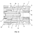
- distal end 125 of the connecting tube 124 of the female connector 100 does not necessarily penetrate into the distal end of the tubular body 30. It is sufficient that it is adjacent to it, as illustrated in FIGS. figures 12 and 13 .
- the tubular body 30 opens along its slot 35a. This opening is facilitated by the presence of the lateral tabs 35b, which give flexibility (in the normal direction to the plane of the slot 35a) at the distal end of the tubular body 30 and allow its elastic deformation under the action of the connection tube 124 on the valve 40.
- valve 40 partially sags and the lateral lugs 35b of the tubular body 30 deform elastically so as to move away from each other, thereby reducing the axial resistance they exert on the valve 40 to facilitate the passage of the distal end 125.
- the sliding ring 50 is close to its connection position, so that it does not prevent this opening. On the other hand, in the rest position, the sliding ring 50 tends to hold the slot 35a of the tubular body 30 closed.
- the spacing of the edges of the slot 42 can also be facilitated by the groove 44.
- the operator unlocks the locking means of the connectors 1 and 100, for example by rotating the connectors relative to each other in the case of bayonet locking means, then discards the connectors 1, 100 with the help of the thrust of the elastic means 131 and the return means 60.
- the free end 125 of the connection tube 124 exits the valve 40, which allows to close the slot 42.
- This closure of the slot 42 is further improved by the elastic return of the lateral tabs 35b, which tends to bring the lateral tabs 35b in the initial rest position, in which the lateral tabs 35b exert a radial force towards the internal channel 31 on the slot 42.
- the membrane 130 then gradually covers the free end 125 of the tube 124 to seal it tightly: the membrane 130 is then in the rest position.
- valve 40 and the tubular body 30 leave the distal connector 140 of the female connector 100, which itself progressively leaves the distal connector 10 of the male connector 1, thus leaving the sliding ring 50 to return to its rest position.
- sealing is ensured throughout the operation. Indeed, the sealing is ensured by the contact at any time of the membrane 130 and the valve 40.
- the membrane 130 and the valve 40 are traversed only by a single element, namely the connection tube 124 which is in addition very thin, while in the prior art, the male connector also includes a tube connection that crosses the two membranes.
- the connection tube of the male connectors of the prior art is also relatively large, compared with the connecting tube 124, so that the slot of the diaphragm 130 and the slot 42 of the valve 40 have to open further to let him pass.
- the slot 133 of the diaphragm 130 and the valve 40 thus opens much less than in the prior art, so that it becomes much more difficult for the fluid to penetrate, thus reducing the formation of drops at the time of disconnection.
Landscapes
- Engineering & Computer Science (AREA)
- General Engineering & Computer Science (AREA)
- Health & Medical Sciences (AREA)
- Heart & Thoracic Surgery (AREA)
- Mechanical Engineering (AREA)
- Anesthesiology (AREA)
- Hematology (AREA)
- Life Sciences & Earth Sciences (AREA)
- Animal Behavior & Ethology (AREA)
- General Health & Medical Sciences (AREA)
- Public Health (AREA)
- Veterinary Medicine (AREA)
- Biomedical Technology (AREA)
- Pulmonology (AREA)
- Infusion, Injection, And Reservoir Apparatuses (AREA)
- Quick-Acting Or Multi-Walled Pipe Joints (AREA)
Description
L'invention concerne un connecteur pour un circuit de fluide, notamment à usage médical.The invention relates to a connector for a fluid circuit, in particular for medical use.
Il est connu du document
On a ensuite proposé dans la demande internationale
Cet ensemble de connexion présente l'avantage de réduire le nombre d'étapes nécessaires pour son assemblage par un opérateur. Par ailleurs, il comprend des moyens de connexion facilement nettoyables, notamment au niveau des parties distales des connecteurs, dans la mesure où les membranes affleurent l'extrémité distale des connecteurs.This connection assembly has the advantage of reducing the number of steps required for its assembly by an operator. Furthermore, it includes easily cleanable connection means, particularly at the distal portions of the connectors, insofar as the membranes are flush with the distal end of the connectors.
Par ailleurs, le document
Le document
Enfin, le document
Il est important pour ces connecteurs médicaux pour circuit liquide de limiter voir supprimer les risques de formation d'une goutte en sortie des connecteurs, au moment de leur séparation. En effet, les produits transférés par l'intermédiaire de ces connecteurs sont généralement des médicaments plus ou moins dilués, qui peuvent donc être dangereux pour les utilisateurs ou les patients si ceux-ci s'y trouvent régulièrement exposés, comme cela peut être le cas pour les préparateurs de médicaments. La formation de gouttes en sortie des connecteurs peut en outre être source de contaminations croisées dans les préparations des médicaments elles-mêmes.It is important for these medical connectors for liquid circuits to limit or eliminate the risk of forming a drop at the output of the connectors, at the time of their separation. Indeed, the products transferred through these connectors are generally more or less diluted drugs, which can be dangerous for users or patients if they are regularly exposed to them, as may be the case. for drug preparers. The formation of drops out of the connectors may also be a source of cross-contamination in the preparations of the drugs themselves.
Un objectif de l'invention est donc de proposer un nouvel ensemble de connecteurs mâle et femelle à connexion sécurisée pour un circuit de fluide, dont la membrane et le corps soient parfaitement nettoyables, tout en limitant voire supprimant la formation de gouttes lors de la séparation des connecteurs.An object of the invention is therefore to provide a new set of male and female connectors with secure connection for a fluid circuit, the membrane and the body are perfectly cleanable, while limiting or eliminating the formation of drops during separation connectors.
De manière secondaire, un autre objectif de la demande est de proposer un ensemble de connecteurs pour un circuit de fluide qui limite les risques de dégradation des fluides le traversant, tels que les risques de destruction du culot globulaire.In a secondary manner, another objective of the application is to propose a set of connectors for a fluid circuit that limits the risks of degradation of the fluids passing through it, such as the risks of destruction of the red blood cell.
Pour cela, l'invention propose un connecteur mâle pour un circuit liquide, comprenant :
- un raccord distal comprenant une partie tubulaire définissant un passage,
- un raccord proximal,
- un organe de connexion s'étendant de manière fixe et coaxiale dans la partie tubulaire du raccord distal, ledit organe de connexion étant constitué d'un corps tubulaire sur lequel est fixé, au niveau d'une extrémité libre, une valve cylindrique déformable élastiquement et fermée au niveau d'une extrémité distale par une épaisseur de valve traversée par une fente, et
- une bague coulissante montée sur le corps tubulaire, ladite bague coulissante étant mobile entre une position inactive, dans laquelle elle encapsule les parois de la valve en laissant libre l'extrémité distale de ladite valve, et une position de connexion, dans laquelle elle est située à distance de l'extrémité distale de la valve et dévoile tout ou partie des parois latérales de la valve.
- a distal connector comprising a tubular portion defining a passage,
- a proximal connection,
- a connecting member extending fixedly and coaxially in the tubular portion of the distal connector, said connecting member being constituted by a tubular body on which is fixed, at a free end, a cylindrical valve elastically deformable and closed at a distal end by a valve thickness traversed by a slot, and
- a sliding ring mounted on the tubular body, said sliding ring being movable between an inactive position, in which it encapsulates the walls of the valve leaving free the distal end of said valve, and a connection position, in which it is located remote from the distal end of the valve and reveals all or part of the side walls of the valve.
Certains aspects préférés mais non limitatifs du connecteur mâle selon l'invention sont les suivants :
- il comprend en outre un moyen de rappel prenant appui entre la bague coulissante et le corps tubulaire, et adapté pour ramener la bague coulissante vers sa position de repos ;
- la valve ferme l'extrémité libre du corps tubulaire de manière étanche ;
- la valve présente en outre au moins une gorge borgne débouchant sur le corps tubulaire, ladite gorge s'étendant de manière sensiblement parallèlement à la fente, coaxialement au corps tubulaire, ou autour de la fente ;
- la valve est surmoulée sur le corps tubulaire ;
- l'extrémité distale de la valve présente une surface concave ;
- en position de repos, une surface distale de l'extrémité distale de la valve affleure une surface distale de l'extrémité distale de la bague coulissante ;
- la valve comprend en outre, au niveau de la fente, une surépaisseur radiale s'étendant coaxialement au corps tubulaire ;
- la surépaisseur a la forme d'une ellipse dont un petit diamètre est sensiblement égal à un diamètre interne de la bague coulissante et un grand diamètre mesure quelques dixièmes de millimètres de plus que le petit diamètre ;
- le raccord distal encapsule le corps tubulaire et la bague coulissante de manière à ne laisser libre que leurs extrémités distales respectives ;
- la bague coulissante comprend en outre un joint d'étanchéité s'étendant entre la bague coulissante et le raccord distal ;
- le joint d'étanchéité est disposé dans une cavité radiale de ladite bague coulissante, ou surmoulé sur ladite bague coulissante ;
- l'extrémité distale du corps tubulaire comprend un épaulement adapté pour recevoir la valve, de sorte qu'une surface externe des parois latérales de la valve et du corps tubulaire est continue ;
- le corps tubulaire définit un canal interne de section sensiblement constante ;
- le raccord distal comprend en outre des moyens de verrouillage ;
- les moyens de verrouillage sont à baïonnettes ;
- une extrémité distale du raccord distal présente des parois de centrage dans le prolongement du raccord distal ;
- le corps tubulaire présente en outre une fente s'étendant parallèlement à la fente de la valve depuis son extrémité distale en direction de son extrémité proximale, de manière à définir deux pattes latérales ; et
- la fente de la valve est biseautée en direction du corps tubulaire.
- it further comprises a return means bearing support between the sliding ring and the tubular body, and adapted to return the sliding ring to its rest position;
- the valve closes the free end of the tubular body in a sealed manner;
- the valve further has at least one blind groove opening on the tubular body, said groove extending substantially parallel to the slot, coaxially with the tubular body, or around the slot;
- the valve is overmolded on the tubular body;
- the distal end of the valve has a concave surface;
- in the rest position, a distal surface of the distal end of the valve is flush with a distal surface of the distal end of the sliding ring;
- the valve further comprises, at the slot, a radial extra thickness extending coaxially with the tubular body;
- the overthickness has the shape of an ellipse whose small diameter is substantially equal to an internal diameter of the sliding ring and a large diameter measures a few tenths of a millimeter more than the small diameter;
- the distal fitting encapsulates the tubular body and the sliding ring so as to leave free only their respective distal ends;
- the sliding ring further comprises a seal extending between the sliding ring and the distal connector;
- the seal is disposed in a radial cavity of said sliding ring, or overmolded on said sliding ring;
- the distal end of the tubular body comprises a shoulder adapted to receive the valve, so that an outer surface of the side walls of the valve and the tubular body is continuous;
- the tubular body defines an internal channel of substantially constant section;
- the distal connector further comprises locking means;
- the locking means are bayonet;
- a distal end of the distal connector has centering walls extending from the distal connector;
- the tubular body further has a slot extending parallel to the slot of the valve from its distal end towards its proximal end, so as to define two side tabs; and
- the slot of the valve is beveled towards the tubular body.
Selon un deuxième aspect, l'invention propose un procédé de fabrication d'un connecteur mâle conforme à l'invention, comprenant les étapes consistant à :
- prévoir un corps tubulaire ;
- fixer la valve sur une extrémité distale du corps tubulaire ;
- fixer le corps tubulaire sur le raccord proximal;
- monter la bague coulissante sur l'extrémité distale du corps tubulaire ; et
- fixer le raccord distal sur le corps tubulaire.
- provide a tubular body;
- fix the valve on a distal end of the tubular body;
- attach the tubular body to the proximal connector;
- mounting the sliding ring on the distal end of the tubular body; and
- attach the distal connector to the tubular body.
Certains aspects préférés mais non limitatifs du corps tubulaire conforme à l'invention sont les suivants :
- il comprend en outre une étape au cours de laquelle on réalise la fente dans la valve après fixation de la valve sur l'extrémité distale à du corps tubulaire ; et
- la valve est fixée par surmoulage sur le corps tubulaire.
- it further comprises a step during which the slot is made in the valve after fixing the valve on the distal end to the tubular body; and
- the valve is fixed by overmoulding on the tubular body.
Selon un troisième aspect, l'invention propose un ensemble de connexion pour un circuit liquide, comprenant un connecteur mâle conforme à l'invention, et un connecteur femelle, ledit connecteur femelle comprenant :
- un raccord distal, et
- un raccord proximal, le raccord distal comprenant une partie tubulaire, dans laquelle s'étend de manière coaxiale un organe de connexion monté fixe sur le raccord proximal, et une membrane cylindrique déformable élastiquement fermée au niveau d'une extrémité distale par un septum traversé par une fente, et mobile entre une position d'obturation, dans laquelle la membrane recouvre une extrémité libre de l'organe de connexion de manière étanche, et une position de connexion, dans laquelle la membrane et la valve sont traversées par l'organe de connexion.
- a distal connection, and
- a proximal connector, the distal connector comprising a tubular portion, in which coaxially extends a connection member fixedly attached to the proximal connector, and a deformable cylindrical membrane resiliently closed at a distal end by a septum traversed by a slot, and movable between a closed position, in which the membrane covers a free end of the connection member sealingly, and a connection position, in which the membrane and the valve are traversed by the member of connection.
Certains aspects préférés mais non limitatifs de l'ensemble sont les suivants :
- la forme et les dimensions de la valve du connecteur mâle sont sensiblement égales à la forme et aux dimensions de la membrane, de sorte que lors de la connexion du connecteur mâle avec le connecteur femelle, la valve est apte à pénétrer dans l'extrémité distale du raccord distale du connecteur femelle ;
- l'extrémité distale de la membrane présente une surface convexe, tandis que l'extrémité distale de la valve présente une surface concave, la concavité de la surface de l'extrémité distale de la valve correspondant à la convexité de surface de l'extrémité distale de la membrane ;
- le connecteur femelle et le connecteur mâle comprennent chacun des moyens de verrouillage complémentaires à baïonnettes ;
- les dimensions et la forme du raccord distal du connecteur femelle sont sensiblement identiques aux dimensions et à la forme de la bague coulissante, de sorte que lors de la connexion du connecteur mâle avec le connecteur femelle, l'extrémité distale du connecteur femelle soit apte à pénétrer dans l'extrémité distale du raccord distal du connecteur mâle ; et
- le corps tubulaire du connecteur mâle présente en outre une fente s'étendant parallèlement à la fente de la valve depuis son extrémité distale en direction de son extrémité proximale de manière à définir deux pattes latérales, et dans lequel les pattes latérales du connecteur mâle se déforment élastiquement lors de la pénétration de l'organe de connexion du connecteur femelle dans la fente de la valve du connecteur mâle.
- the shape and dimensions of the valve of the male connector are substantially equal to the shape and dimensions of the membrane, so that when the male connector is connected to the female connector, the valve is able to penetrate into the distal end the distal connector of the female connector;
- the distal end of the membrane has a convex surface, while the distal end of the valve has a concave surface, the concavity of the surface of the distal end of the valve corresponding to the surface convexity of the distal end of the membrane;
- the female connector and the male connector each comprise complementary bayonet locking means;
- the dimensions and the shape of the distal connector of the female connector are substantially identical to the dimensions and the shape of the sliding ring, so that when the male connector is connected to the female connector, the distal end of the female connector is adapted to penetrate the distal end of the distal connector of the male connector; and
- the tubular body of the male connector further has a slot extending parallel to the slot of the valve from its distal end towards its proximal end so as to define two lateral tabs, and wherein the lateral tabs of the male connector deform elastically during the penetration of the connecting member of the female connector in the slot of the valve of the male connector.
Selon un quatrième aspect, l'invention propose l'utilisation d'un ensemble de connecteurs conforme à l'invention, comprenant les étapes consistant à :
- placer l'extrémité distale (120) du connecteur femelle (100) contre l'extrémité distale (10) du connecteur mâle (1), de sorte que la valve (40) soit en contact avec la membrane (130);
- insérer le raccord distal (140) du connecteur femelle (100) dans le raccord distal (10) du connecteur mâle (1), en poussant le connecteur femelle (100) en direction du connecteur mâle (1), de sorte que la valve (40) pénètre dans l'extrémité distale du raccord distal (140) du connecteur femelle (100) et que le raccord distal (10) du connecteur mâle (1) déplace la bague coulissante (50) en direction du raccord proximal du connecteur mâle (1), jusqu'à ce que l'organe de connexion (124) du connecteur femelle (100) traverse à la fois la membrane (130) et la valve (40) ; et
- verrouiller l'ensemble.
- placing the distal end (120) of the female connector (100) against the distal end (10) of the male connector (1) so that the valve (40) is in contact with the membrane (130);
- insert the distal connector (140) of the female connector (100) into the distal connector (10) of the male connector (1), pushing the female connector (100) towards the male connector (1), so that the valve (40) enters the distal end of the distal connector (140) of the female connector (100) and the distal connector (10) of the male connector (1) moves the slide ring (50) towards the proximal connector of the male connector (1) until the connection member (124) of the female connector (100) passes through both the diaphragm (130) and the valve (40); and
- lock the set.
D'autres caractéristiques, buts et avantages de la présente invention apparaîtront mieux à la lecture de la description détaillée qui va suivre, et en regard des dessins annexés donnés à titre d'exemples non limitatifs et sur lesquels :
- La
figure 1 est une vue en perspective d'une forme de réalisation d'un connecteur femelle pouvant être utilisé dans un ensemble conforme à l'invention ; - La
figure 2 est une vue en coupe du connecteur femelle de lafigure 1 ; - La
figure 3 est une vue en perspective d'une forme de réalisation d'un connecteur mâle conforme à l'invention ; - La
figure 4 est une vue en coupe du connecteur mâle de lafigure 3 ; - La
figure 5A est une vue en coupe d'un exemple de réalisation d'un corps tubulaire sur lequel est fixé une valve conforme à l'invention ; - La
figure 5B est une vue en perspective de la partie distale de l'exemple de réalisation de lafigure 5A ; - La
figure 6 est une vue en perspective d'une forme de réalisation de la partie distale d'un corps tubulaire conforme à l'invention ; - La
figure 7A est une vue en perspective d'une section d'un exemple de réalisation d'une valve conforme à l'invention ; - La
figure 7B est une vue en coupe de lafigure 7A ; - La
figure 7C est une vue en perspective de la partie proximale d'une valve conforme à lafigure 7A ; - La
figure 8A est une vue en perspective d'un ensemble comprenant le corps tubulaire et la valve de lafigure 5B , un exemple de réalisation d'une bague coulissante et un exemple de réalisation d'un moyen élastique conformes à l'invention ; - La
figure 8B est une vue en coupe de la partie distale de l'ensemble de lafigure 7 ; - La
figure 9 est une vue de côté d'un connecteur femelle et d'un connecteur mâle en contact avant assemblage ; - La
figure 10 est une vue de coupe des connecteurs femelle et mâle de lafigure 9 ; - La
figure 11 est une vue de côté d'un connecteur femelle et d'un connecteur mâle connectés et verrouillés ; - La
figure 12 est une vue de coupe des connecteurs femelle et mâle de lafigure 11 ; - La
figure 13 est une vue en détail de la connexion du connecteur femelle avec le connecteur mâle de lafigure 12 .
- The
figure 1 is a perspective view of an embodiment of a female connector that can be used in an assembly according to the invention; - The
figure 2 is a sectional view of the female connector of thefigure 1 ; - The
figure 3 is a perspective view of an embodiment of a male connector according to the invention; - The
figure 4 is a sectional view of the male connector of thefigure 3 ; - The
Figure 5A is a sectional view of an exemplary embodiment of a tubular body on which is fixed a valve according to the invention; - The
Figure 5B is a perspective view of the distal portion of the exemplary embodiment of theFigure 5A ; - The
figure 6 is a perspective view of an embodiment of the distal portion of a tubular body according to the invention; - The
Figure 7A is a perspective view of a section of an exemplary embodiment of a valve according to the invention; - The
Figure 7B is a sectional view of theFigure 7A ; - The
Figure 7C is a perspective view of the proximal portion of a valve according to theFigure 7A ; - The
figure 8A is a perspective view of an assembly comprising the tubular body and the valve of theFigure 5B , an embodiment of a sliding ring and an embodiment of an elastic means according to the invention; - The
Figure 8B is a sectional view of the distal part of the whole of thefigure 7 ; - The
figure 9 is a side view of a female connector and a male connector in contact before assembly; - The
figure 10 is a sectional view of the female and male connectors of thefigure 9 ; - The
figure 11 is a side view of a connected and locked female connector and male connector; - The
figure 12 is a sectional view of the female and male connectors of thefigure 11 ; - The
figure 13 is a detailed view of the connection of the female connector with the male connector of thefigure 12 .
En référence aux
Le connecteur femelle 100 comporte un raccord proximal 120, une membrane 130 déformable élastiquement, sensiblement tubulaire, et un raccord distal 140 solidaire du raccord proximal 120.The
Le raccord proximal 120 est de forme générale tubulaire et comporte une extrémité proximale qui comprend, ici, une entrée connectable 121 de type "Luer-Lock" femelle. En variante de réalisation, cette entrée connectable 121 est de type "Luer-Lock" mâle. Elle se prolonge, en direction distale, par un corps creux 122.The
Le corps creux 122 du raccord proximal 120 se termine, en direction distale, par un rebord 123 de forme circulaire surmonté de manière coaxiale par un tube de connexion creux 124 qui s'étend en saillie du raccord proximal 120 en direction distale. Le tube creux 124 se termine par une extrémité libre 125 distale et forme un organe de connexion.The
Nous allons maintenant décrire plus en détail la membrane 130 du connecteur 100.We will now describe in more detail the
Cette membrane 130 présente une extrémité distale 132, et comporte des moyens élastiques 131.This
Ici, les moyens élastiques 131 sont un ressort 131, par exemple du type ressort de compression hélicoïdal, s'étendant jusqu'à l'extrémité distale 132. Ils sont destinés à prendre appui sur le raccord proximal 120 et à venir pousser l'extrémité distale 132 de la membrane 130 de manière à ce que cette dernière vienne dans une position de repos (inactive), dans laquelle elle obture une extrémité distale du passage 141.Here, the
L'extrémité distale 132 de la membrane 130 est un septum présentant une surface distale globalement convexe traversée par une fente coaxiale au tube de connexion 124.The
Ainsi le connecteur femelle 100 comporte une membrane 130 qui est encapsulée dans la partie tubulaire du raccord distal 140, de sorte que seule la surface distale traversée par la fente soit accessible par un opérateur. Ceci permet, au surplus, en position de repos, un serrage radial de la membrane 130, et en particulier de l'extrémité distale 132 de cette dernière, réalisé par une paroi de la partie tubulaire du raccord distal 140 : une meilleure étanchéité et une tenue en contre-pression améliorée sont alors obtenues.Thus the
Sur sa périphérie, de préférence en partie proximale, le raccord distal 140 comporte un moyen de verrouillage 150. Ici, le moyen de verrouillage est femelle et à baïonnettes et comprend une jupette 151 pourvue de gorges adaptées pour coopérer avec des ergots mâles d'un moyen de verrouillage à baïonnettes complémentaire. Dans la forme de réalisation illustrée sur les
Ces moyens de verrouillage 150 seront détaillés plus loin dans la description.These locking means 150 will be detailed later in the description.
Une description plus détaillée d'un connecteur similaire au connecteur 100 est fournie dans le document
Nous allons à présent décrire un connecteur mâle 1 selon l'invention en référence aux
Le connecteur mâle 1 comprend un raccord distal 10 comportant une partie tubulaire définissant un passage, un raccord proximal 20 et un organe de connexion 30.The
L'organe de connexion 30 s'étend dans le passage 11 du raccord distal 10, coaxialement à la partie tubulaire de celui-ci. Il a la forme d'un corps globalement tubulaire formant un canal interne 31 globalement cylindrique de révolution, et présente une valve 40 au niveau d'une extrémité distale 32.The connecting
Le corps tubulaire 30 est inséré dans le raccord distal 10 de telle sorte que la valve 40 soit adjacente à l'extrémité distale 11 du raccord distal.The
Il comprend en outre un renflement radial 33 adapté pour venir en prise avec l'extrémité proximale du raccord distal 12. Par exemple, le renflement 33 présente la forme d'un disque s'étendant transversalement à l'axe du corps tubulaire, dont le diamètre externe est sensiblement égal au diamètre interne du raccord distal 10. Le disque présente en outre des moyens d'encliquetage 33a, par exemple une saillie radiale pouvant être annulaire, adaptée pour coopérer avec une gorge 13 de forme complémentaire réalisée dans la face interne du raccord distal 10, et est prolongé par une collerette 33b de plus grand diamètre formant butée pour le raccord distal 10. Ainsi, lorsque le corps tubulaire 30 est inséré dans le raccord distal 10, l'extrémité proximale 12 du raccord distal 10 vient en appui contre la collerette 33b formant butée et vient en prise avec la saillie annulaire 33a, de sorte que le raccord distal 10 se trouve bloqué en translation par rapport au corps tubulaire 30.It further comprises a
Enfin, le corps tubulaire 30 se prolonge en partie proximale au-delà du renflement radial 33 par une zone 34 d'accrochage au raccord proximal 20. La zone d'accrochage 34 comprend un corps cylindrique présentant, au niveau d'une face externe, au moins un organe de connexion 34a. De préférence, la zone d'accrochage 34 est cylindrique de révolution, l'organe de connexion 34a ayant alors la forme d'une protubérance annulaire. De la sorte, le raccord proximal 20 est fixé en translation sur le corps tubulaire 30 mais libre en rotation autour de celui-ci, afin d'éviter des desserrages accidentels du raccord proximal 20 du connecteur mâle 1.Finally, the
La valve 40 du corps tubulaire 30 est une membrane élastiquement déformable, de forme globalement cylindrique, et fermée au niveau d'une extrémité distale 41 par une membrane. Le diamètre extérieur de la valve 40 est inférieur ou égal au diamètre extérieur de la membrane 130, de préférence sensiblement égal.The
L'épaisseur de membrane est traversée par une fente 42 qui débouche sur le corps tubulaire 30. L'extrémité distale du corps tubulaire 32 et la fente 42 peuvent être séparées par un espace interne 43 prolongeant le canal interne 31.The membrane thickness is traversed by a
La fente 42 peut être droite ou biseautée en direction du corps tubulaire 30, en fonction notamment de son procédé de fabrication.The
Par exemple, la valve 40 est réalisée dans un matériau élastomère permettant de fermer le corps tubulaire 30 de manière étanche malgré la présente de la fente 42. Typiquement, la valve 40 peut être réalisée dans du silicone LSR (acronyme anglais de Liquid Silicon Rubber, pour caoutchouc silicone liquide), tandis que le corps tubulaire 30 est réalisé dans un matériau plastique, tel qu'une résine plastique PBT (Polybutylène Téréphtalate). Elle peut alors être surmoulée sur le corps tubulaire 30. Dans ce cas, afin d'améliorer la liaison entre la valve 40 et le corps tubulaire 30, l'extrémité distale du corps tubulaire 30 peut notamment être traversée radialement par un ou plusieurs orifices 36. Par ailleurs, la fente 42 est de préférence réalisée par découpe à travers l'épaisseur de membrane après fixation de la valve 40 sur le corps tubulaire 30, par exemple à l'aide d'un scalpel, de manière à être indexée avec précision par rapport au corps tubulaire 30.For example, the
Avantageusement, l'extrémité distale 32 du corps tubulaire 30, sur laquelle est fixée la valve 40, présente un épaulement annulaire 32a formé par rétrécissement de la paroi du corps tubulaire 30 afin de recevoir la valve 30 sans créer de discontinuité au niveau de la surface externe de l'organe de connexion. La valve 40 est alors surmoulée (ou fixée) sur cet épaulement 32a sur une épaisseur telle que la paroi externe 46 de la valve 40 et le corps tubulaire 30 forment une surface continue et globalement lisse.Advantageously, the
Selon une forme de réalisation, la valve 40 comprend en outre au moins une gorge borgne 44 débouchant sur le corps tubulaire 30 et qui est coaxiale au corps tubulaire 30.According to one embodiment, the
La gorge 44 a un effet double sur la fente 42.The
Lors de l'ouverture de la fente 42 par introduction d'un objet depuis l'extrémité distale 41 de celle-ci, comme nous le verrons plus bas dans la description, la gorge 44 permet à la fente 42 de s'ouvrir plus facilement, les bords de la fente 42 n'étant pas retenus en raison de l'espace vide créé par la gorge 44.When opening the
Par ailleurs, lorsque la fente 42 est fermée (et donc non traversée par un objet tel que le tube de connexion 124), en cas de remontée de fluide en provenance du corps tubulaire 30, le fluide pénètre dans la gorge 44 et applique une pression sur les bords de la fente qui tend à plaquer les bords de la fente 42 l'un vers l'autre. La fente 42 est donc maintenue fermée et empêche le fluide de sortir, augmentant ainsi l'étanchéité du connecteur 1.Moreover, when the
La gorge 44 peut par exemple être de forme annulaire et s'étendre autour et à distance de la fente, transversalement à l'axe du corps tubulaire 30. En variante, la valve 40 comprend deux gorges 44 sensiblement rectilignes s'étendant parallèlement à la fente 42, de part et d'autre de celle-ci. Cette forme de réalisation présente l'avantage d'appliquer une pression plus efficace sur la fente 42, et donc d'améliorer sa résistance en contre-pression. Selon une autre variante encore, les gorges 44 sont courbes et de part et d'autre de la fente.The
Enfin, selon une forme de réalisation, l'extrémité distale 41 de la valve 40 est une surface concave. La surface de l'extrémité distale de la membrane 130 du connecteur femelle 100 étant de forme convexe, cela permet à l'extrémité distale de la valve 40 d'épouser parfaitement la surface de la membrane 130, et de limiter ainsi la fuite de fluide lorsque les connecteurs 1 et 100 sont connectés ensemble. De préférence, la concavité de l'extrémité distale 41 de la valve 40 correspond à la convexité de l'extrémité distale de la membrane 130.Finally, according to one embodiment, the
En variante, la surface de l'extrémité distale de la membrane 130 du connecteur femelle 100 est de forme concave ; l'extrémité distale 41 de la valve 40 est alors une surface convexe de convexité correspondante.Alternatively, the surface of the distal end of the
Le connecteur mâle 1 comprend en outre une bague coulissante 50 montée sur le corps tubulaire 30, mobile entre une position inactive dite de repos et une position de connexion.The
Dans la position de repos, la bague 50 encapsule les parois latérales 46 de la valve 40, en laissant libre son extrémité distale 41. De préférence, l'extrémité distale 41 de la valve 40 affleure la surface de l'extrémité distale 51 de la bague 50, de manière à minimiser les arêtes et à faciliter le nettoyage du connecteur 1. Cette position est notamment illustrée en
Dans la position de connexion, illustrée notamment sur les
Avantageusement, le diamètre interne de la bague 50 est sensiblement égal au diamètre externe du corps tubulaire 30 et de la valve 40.Advantageously, the internal diameter of the
La valve 40 peut en outre présenter une légère surépaisseur 45 (de l'ordre de 5% de l'épaisseur totale de la valve 40) s'étendant radialement au niveau de son extrémité distale 41, de manière adjacente à la fente 42. De la sorte, en position de repos, la bague 50, dont le diamètre interne est légèrement plus petit que le diamètre externe de la valve 40 au niveau de la surépaisseur 45, exerce une force radiale centripète sur la valve 40 et la fente 42. Par conséquent, au repos, la bague 50 augmente encore la résistance en contre-pression de la valve 40.The
Par ailleurs, la surépaisseur 45 permet d'éviter le passage de fluide entre la bague 50 et la valve 40.Moreover, the
Dans la forme de réalisation illustrée sur les figures, la surépaisseur 45 n'est présente que de chaque côté de la fente 42, afin que la pression ne soit exercée que de part et d'autre de celle-ci, améliorant ainsi sa résistance en contre-pression. Par exemple, la surépaisseur peut avoir la forme d'une ellipse dont le petit diamètre (au niveau des extrémités de la fente 42) est sensiblement égal au diamètre interne de la bague 50 tandis que le grand diamètre (au niveau des bords de la fente 42) mesure quelques dixièmes de millimètres de plus que le petit diamètre.In the embodiment illustrated in the figures, the
Le diamètre externe de la bague coulissante 50 est de préférence sensiblement égal au diamètre interne du raccord distal 10, de manière à limiter le passage de fluide entre la bague 50 et le raccord 10. Le cas échéant, la surface externe de la bague 50 peut en outre comprendre une rainure annulaire 52 adaptée pour recevoir un joint torique 53 d'étanchéité, afin d'augmenter encore l'étanchéité du connecteur 1 et d'éviter l'introduction de produits tels que des produits désinfectants.The outer diameter of the sliding
Le joint torique 53 peut par exemple être réalisé dans un matériau élastomérique, tel que du silicone LSR.The O-
En variante, le joint torique 53 est surmoulé directement sur la bague 50, avec ou sans rainure annulaire 52.Alternatively, the O-
La surface interne de la bague 50, qui est en contact avec la valve 40, est de préférence lisse, et peut avoir subi pour cela un traitement de surface de manière à faciliter le mouvement de la bague 50 le long du corps tubulaire 30. Par exemple, la face interne de la bague 50 peut être siliconée.The inner surface of the
Le glissement de la bague 50 est encore amélioré par le fait que la surface externe de la valve 40 et du corps tubulaire 30 est continue et de diamètre constant.The sliding of the
La bague 50 peut par exemple être réalisée dans un matériau plastique du type PBT.The
Le connecteur mâle 1 comprend en outre un moyen de rappel 60, adapté pour ramener la bague coulissante 50 dans sa position de repos.The
Dans les formes de réalisation illustrées sur les figures, le moyen de rappel 60 est un ressort élastique coaxial au corps tubulaire 30, s'étendant entre la face proximale 54 de la bague coulissante 50 et la face distale du renfoncement radial 33 du corps tubulaire 30. De la sorte, lorsque la bague coulissante 50 est déplacée en direction de sa position de connexion, le ressort 60 exerce sur la bague 50 une force de rappel qui tend à pousser la bague 50 en direction inverse, vers l'extrémité distale du connecteur 1.In the embodiments illustrated in the figures, the return means 60 is an elastic spring coaxial with the
Cette forme de réalisation du moyen de rappel 60 n'est cependant pas limitative. Il peut également s'agir d'un soufflet travaillant en compression, etc.This embodiment of the return means 60 is however not limiting. It can also be a bellows working in compression, etc.
De préférence, lorsque le moyen de rappel 60 est au repos, la bague coulissante 50 se trouve également en position de repos.Preferably, when the return means 60 is at rest, the sliding
Selon une forme de réalisation illustrée en particulier sur la
Avantageusement, la fente 35a du corps tubulaire 30 est sensiblement parallèle à la fente 42 de la valve 40.Advantageously, the
Par ailleurs, selon une forme de réalisation préférée, la fente 35a est réalisée dans le corps tubulaire 30 de sorte que les bords formant ladite fente 35a soient distants l'un de l'autre. La partie distale du corps tubulaire 30 est donc formée de deux pattes latérales 35b séparées par la fente 35a, comme illustré sur la
Avantageusement, dans la position de repos de la bague coulissante 50, les pattes latérales 35b du corps tubulaire 30 sont contraintes radialement par la bague 50 en direction du canal interne 31 du corps tubulaire 30 afin d'améliorer encore l'étanchéité de la fente 42 de la valve 40, ce qui améliore la tenue en contre-pression de la valve 40.Advantageously, in the rest position of the sliding
Par ailleurs, l'espace créé par la fente 35a permet de la réalisation d'une fente 42 de largeur quelconque, sans qu'elle soit limitée par la partie distale du corps tubulaire 30.Moreover, the space created by the
Nous verrons dans la suite de la description la fonction de cette fente 35a dans le connecteur mâle 1.We will see in the following description the function of this
Le raccord distal 10 est fixé sur le corps tubulaire 30 et la bague coulissante 50, de sorte que son extrémité distale 12 vienne en butée et en prise avec le renflement radial 33 et qu'il encapsule la bague coulissante 50 et la valve 40. Le raccord distal 10 est donc immobile en translation par rapport au corps tubulaire 30. Selon la forme de réalisation des moyens d'encliquetage 33a, le raccord distal peut en revanche être mobile en rotation autour du corps tubulaire 30, par exemple lorsque la saillie 33 et la gorge 13 sont annulaires et s'étendent coaxialement au corps tubulaire 30.The
Dans la forme de réalisation illustrée en
De préférence, le raccord distal 10 comprend au moins deux parois de centrage 14 en regard, séparées radialement par deux échancrures 15, de manière à faciliter le nettoyage des surfaces distales affleurantes 41 et 51 de la valve 40 et de la bague coulissante 50.Preferably, the
La face interne des parois de centrage 14 peut en outre comprendre des protubérances inclinées 14a s'étendant radialement vers l'intérieur afin d'améliorer encore le guidage d'un connecteur femelle 100.The inner face of the centering
L'extrémité distale 11 du raccord distal 10 comprend en outre des moyens de verrouillage 16, de préférence à baïonnette. Ici, les moyens de verrouillage sont deux ergots mâles 16 d'un système à baïonnette, s'étendant chacun depuis une surface externe d'une paroi de centrage 14.The
En variante (non illustrée sur les figures), l'extrémité distale 11 du raccord distal 10 comprend une jupette distale, présentant des moyens de verrouillage à baïonnette femelles.Alternatively (not shown in the figures), the
Ce type de moyens de verrouillage 16 a l'avantage, en comparaison avec les moyens de verrouillage conventionnels du type filetage, de présenter des surfaces globalement lisses de sorte qu'elles sont faciles d'accès et donc faciles à nettoyer. Par ailleurs, ils assurent un verrouillage simple et sûr du connecteur mâle 1 avec un connecteur femelle 100 correspondant.This type of locking means 16 has the advantage, in comparison with the conventional locking means of the thread type, of presenting generally smooth surfaces so that they are easy to access and therefore easy to clean. Moreover, they provide a simple and secure locking of the
Par ailleurs, le raccord distal 10 comprend en outre des moyens de préhension 15 du connecteur mâle 1. Ici, ils sont au nombre de deux et ont la forme de deux renfoncements qui s'étendent radialement de part et d'autre du raccord distal 10. Ces moyens de manipulation 15 permettent de maintenir fermement le connecteur mâle 1 lors de sa connexion avec un connecteur femelle 100.Furthermore, the
Le raccord proximal 20 comporte quant à lui, au niveau de son extrémité proximale 22, une entrée 23 connectable conventionnelle de type « Luer Lock » femelle, apte à être montée sur une seringue (ou tout autre matériel médical adapté) présentant une extrémité de connexion de type « Luer» mâle « Slip » (lisse) ou « Lock » (avec verrouillage), de façon non représentée sur les figures. Cette entrée connectable 23 est de préférence étanche à des pressions allant jusqu'à 3 bars. Pour cela, par exemple, le diamètre externe de la partie proximale 34 du corps tubulaire 30 est légèrement plus grand que le diamètre interne du raccord proximal 20 au niveau de son entrée connectable 23.The
Par ailleurs, le raccord proximal 20 comprend un organe d'accrochage 24 cylindrique de révolution coaxial avec le corps tubulaire 30, adapté pour coopérer avec l'organe d'accrochage 34a correspondant de la zone d'accrochage du corps tubulaire 30. De la sorte, le raccord proximal 20 est fixé en translation sur le corps tubulaire 30, tout en restant mobile en rotation autour de l'axe de celui-ci. Tout mouvement de rotation involontaire du connecteur mâle 1 (par exemple lors de la déconnexion du connecteur mâle 1 et d'un connecteur femelle 100 par rotation desdits connecteurs 1 et 100 afin de déconnecter leurs moyens de verrouillage à baïonnettes 16) est donc compensé par la libre rotation du raccord distal 20 par rapport au corps tubulaire 30, évitant ainsi des déconnexions accidentelles du connecteur mâle 1 et de la seringue.Furthermore, the
Nous allons à présent décrire un procédé d'utilisation d'un ensemble de connecteurs comprenant un connecteur mâle 1 conforme à l'invention et un connecteur femelle correspondant.We will now describe a method of using a set of connectors comprising a
Ici, le connecteur femelle correspond au connecteur 100 décrit précédemment en référence aux
Au cours d'une première étape, on nettoie les extrémités distales des deux connecteurs 1 et 100. Ce nettoyage est d'autant plus facile que la valve 40 et la membrane 130 des connecteurs mâle 1 et femelle 100 respectivement affleurent l'extrémité distale des raccords distaux de sorte que la surface distale de chaque connecteur 1, 100 soit lisse. Le cas échéant, le remplacement des filetages conventionnels par les moyens de verrouillage à baïonnette 16, 150 facilite également ce nettoyage, grâce au décalage de la jupette 151 du connecteur femelle 100, qui permet d'accéder facilement aux filets de l'extrémité distale 152 du connecteur 100, ainsi qu'à l'absence de filets conventionnels sur les moyens de verrouillage du connecteur mâle.During a first step, the distal ends of the two
Une fois le nettoyage réalisé, l'opérateur met en contact les extrémités distales respectives des connecteurs mâle et femelle 100. Pour cela, il applique la surface concave de la valve 40 sur la surface convexe de la membrane 130 et l'extrémité distale du raccord distal 140 sur l'extrémité distale 51 de la bague coulissante 50, comme cela est illustré sur les
On remarquera que les raccords distaux 140 et 10 des deux connecteurs femelle 100 et mâle 1 sont structurellement similaires (en dehors bien entendu de leurs moyens de verrouillage respectifs) : la membrane 130 et la valve 40 affleurent en effet l'extrémité distale de leur raccord distal 140, 10, de sorte que le couplage/découplage du connecteur mâle 1 et du connecteur femelle 100 n'est réalisé qu'en un seul mouvement axial. Il n'est en effet plus nécessaire de fixer les raccords distaux 140, 10 des connecteurs femelle 100 et mâle 1 avant de commencer à pousser les connecteurs l'un vers l'autre, ces deux opérations étant réalisées simultanément grâce à la structure des raccords distaux 140, 240.It will be noted that the
Ici, l'opérateur place les moyens de verrouillage respectifs du connecteur mâle et femelle en regard, puis les verrouille. Dans l'exemple de réalisation illustré, l'opérateur place par exemple les ergots 16 du connecteur mâle 1 en regard des gorges 150 correspondantes du connecteur femelle 100, puis fait glisser les connecteurs 100, 1 relativement l'un par rapport à l'autre en poussant le connecteur mâle 1, en prenant appui sur les moyens de centrage 14 de son raccord distal 10, vers le connecteur femelle 100.Here, the operator places the respective locking means of the male and female connector opposite, then locks them. In the exemplary embodiment illustrated, the operator places for example the
Au cours de cette manipulation, la valve 40 du connecteur mâle 1 pousse sur l'extrémité distale de la membrane 130 du connecteur femelle 100, tandis que le raccord distal 140 du connecteur femelle 100 pousse sur la bague coulissante 50 du connecteur mâle. En conséquence, la valve 40 et une partie du corps tubulaire 30 du connecteur mâle 1 pénètrent dans le raccord distal 140 du connecteur femelle 100, tandis que l'extrémité distale du raccord distal 140 du connecteur mâle 100 pénètre dans l'extrémité distale 11 du raccord distal 10 du connecteur mâle 1.During this manipulation, the
Pour cela, la valve 40 contraint les moyens élastiques 131 à se comprimer, de sorte que la membrane 30 recule vers sa position de connexion, ce qui force l'extrémité distale 125 du tube creux 124 à traverser, par le biais de la fente 133, le septum situé à l'extrémité distale de la membrane 130. Simultanément, l'extrémité distale du raccord distal 140 du connecteur femelle 100, qui est en appui contre la bague coulissante 50, contraint le moyen de rappel 60 à se comprimer, et déplace ainsi la bague coulissante 50 vers sa position de connexion. La valve 40 et le corps tubulaire 30 en revanche ne se déplacent par rapport au raccord distal 10 et au raccord proximal 20 du connecteur mâle 1.For this, the
De plus, la valve 40 ne s'ouvre pas tant que l'extrémité distale 125 du tube creux 124 du connecteur femelle 100 ne traverse pas la membrane, notamment grâce à la rigidité axiale conférée par la partie distale du corps tubulaire 30 sur laquelle est fixée la valve 40.In addition, the
Selon une forme de réalisation préférée, on choisit le matériau et l'épaisseur de la valve 40 de sorte que celle-ci soit suffisamment résistante lorsqu'elle pousse la membrane 130 pour ne pas s'ouvrir et s'affaisser en direction du corps tubulaire 30. L'objectif en effet est que la valve 40 soit apte à transmettre à la membrane 130 du connecteur femelle 100 la force de poussée appliquée par l'opérateur sur les moyens de préhension 14 pour contraindre la membrane 130 du connecteur femelle 100 à reculer vers sa position de connexion, dans laquelle l'extrémité distale 125 du tube de connexion 124 traverse la membrane 130.According to a preferred embodiment, the material and the thickness of the
Cette résistance à l'affaissement de la valve 40 est en outre renforcée axialement par le fait que la valve 40 est fixée sur la partie distale du corps tubulaire 30. Au surplus, la présence des pattes latérales 35b renforce encore le cas échéant la rigidité axiale de la valve 40.This resistance to the collapse of the
Une fois que l'extrémité distale 125 du tube 124 a traversé l'épaisseur de membrane de l'extrémité distale de la membrane 130, cette extrémité distale 125 du tube 124 est en contact d'appui avec la valve 40 du connecteur mâle 1. Etant donné que l'opérateur continue à pousser les connecteurs mâle 1 et femelle 100 l'un vers l'autre, l'extrémité distale 125 du tube 124 appuie sur l'extrémité distale 41 de la valve 40, pour finalement pénétrer dans la fente 42 de la valve 40. En effet, à ce stade, les moyens élastiques sont déjà fortement comprimés et exercent une force de rappel supérieure à celle des bords de la fente 42, de sorte que ceux-ci cèdent et s'écartent pour laisser le passage au tube de connexion 124.Once the
La poussée se poursuit jusqu'à ce que l'extrémité distale 125 du tube 124 du connecteur femelle 100 soit en connexion fluidique avec le corps tubulaire 30 du connecteur mâle 1. Dès lors, la connexion et un passage de fluide sont réalisés entre les connecteurs mâle 1 et femelle 100.The thrust continues until the
On notera ici que l'extrémité distale 125 du tube de connexion 124 du connecteur femelle 100 ne pénètre pas nécessairement dans l'extrémité distale du corps tubulaire 30. Il suffit en effet qu'elle se trouve adjacente à celui-ci, comme illustré sur les
L'opérateur fait alors tourner les connecteurs l'un par rapport à l'autre afin de positionner les ergots 16 du connecteur mâle en butée dans les gorges correspondantes 150 du connecteur femelle 100, et verrouiller l'ensemble de connecteurs 100, 1.The operator then rotates the connectors relative to each other in order to position the
Afin de faciliter la pénétration de l'extrémité distale 125 du tube de connexion 124 du connecteur femelle 100 dans la fente 42 de la valve 40, le corps tubulaire 30 s'ouvre le long de sa fente 35a. Cette ouverture est facilitée par la présence des pattes latérales 35b, qui confèrent une flexibilité (dans la direction normale au plan de la fente 35a) à l'extrémité distale du corps tubulaire 30 et permettent sa déformation élastique sous l'action du tube de connexion 124 sur la valve 40. De la sorte, lorsque les bords de la fente 42 s'écartent finalement pour laisser le passage à l'extrémité distale 125 du tube de connexion 124, la valve 40 s'affaisse en partie et les pattes latérales 35b du corps tubulaire 30 se déforment élastiquement de manière à s'éloigner l'une de l'autre, réduisant ainsi la résistance axiale qu'elles exercent sur la valve 40 afin de faciliter le passage de l'extrémité distale 125.In order to facilitate the penetration of the
On remarquera que, à ce stade de la connexion, la bague coulissante 50 est proche de sa position de connexion, de sorte qu'elle n'empêche pas cette ouverture. En revanche, en position, de repos, la bague coulissante 50 tend à maintenir la fente 35a du corps tubulaire 30 fermée.It will be noted that at this stage of the connection, the sliding
Le cas échéant, l'écartement des bords de la fente 42 peut également être facilité par la gorge 44.If necessary, the spacing of the edges of the
A la déconnexion, l'opérateur déverrouille les moyens de verrouillage des connecteurs 1 et 100, par exemple en faisant tourner les connecteurs l'un par rapport à l'autre dans le cas de moyens de verrouillage à baïonnettes, puis écarte les connecteurs 1, 100 avec l'aide de la poussée des moyens élastiques 131 et du moyen de rappel 60. Progressivement, l'extrémité libre 125 du tube de connexion 124 sort de la valve 40, ce qui permet de refermer la fente 42. Cette fermeture de la fente 42 est encore améliorée grâce au retour élastique des pattes latérales 35b, qui tend à ramener les pattes latérales 35b en position initiale de repos, dans laquelle les pattes latérales 35b exercent un effort radial en direction du canal interne 31 sur la fente 42.On disconnection, the operator unlocks the locking means of the
La membrane 130 recouvre ensuite progressivement l'extrémité libre 125 du tube 124 jusqu'à l'obturer de manière étanche : la membrane 130 se trouve alors en position de repos.The
Parallèlement, la valve 40 et le corps tubulaire 30 sortent du raccord distal 140 du connecteur femelle 100, qui lui-même sort progressivement du raccord distal 10 du connecteur mâle 1, laissant ainsi la bague coulissante 50 revenir dans sa position de repos.In parallel, the
Lors d'une connexion ou d'une déconnexion, l'étanchéité est assurée tout le long de l'opération. En effet, l'étanchéité est assurée par le contact à tout moment de la membrane 130 et de la valve 40.During a connection or disconnection, sealing is ensured throughout the operation. Indeed, the sealing is ensured by the contact at any time of the
Par ailleurs, les risques de formation d'une goutte au moment de la déconnexion sont fortement limités, voire supprimés. En effet, la membrane 130 et la valve 40 ne sont plus traversées que par un seul élément, à savoir le tube de connexion 124 qui est au surplus très fin, alors que dans l'art antérieur, le connecteur mâle comprend lui aussi un tube de connexion qui traverse les deux membranes. Le tube de connexion des connecteurs mâles de l'art antérieur est en outre relativement gros, en comparaison avec le tube de connexion 124, de sorte que la fente de la membrane 130 et la fente 42 de la valve 40 doivent davantage s'ouvrir pour le laisser passer.Moreover, the risk of forming a drop at the time of disconnection is greatly limited or even eliminated. Indeed, the
En utilisant un tube de connexion fin 124 pour le connecteur femelle 100, la fente 133 de la membrane 130 et de la valve 40 s'ouvrent donc beaucoup moins que dans l'art antérieur, de sorte qu'il devient beaucoup plus difficile pour le fluide d'y pénétrer, diminuant ainsi la formation de gouttes au moment de la déconnexion.By using a
Bien entendu, il est possible d'apporter à l'invention de nombreuses modifications sans sortir du cadre de celle-ci.Of course, it is possible to bring to the invention many modifications without departing from the scope thereof.
Claims (17)
- A male connector (1) for a liquid circuit, including:- a distal hub (10) including a tubular portion defining a passage,- a proximal hub (20),- a connection member (30) extending fixedly and coaxially within the tubular portion of the distal hub (10), said connection member consisting of a tubular body (30) whereon is fastened, at a free end (32), a cylindrical, elastically deformable valve (40) closed at a distal end (41) by a thickness of valve through which passes a slit (42),characterized in that it also includes a sliding ring (50) mounted on the tubular body (30), said sliding ring (50) being movable between an inactive position, wherein it encapsulates the walls (46) of the valve (40) while leaving free the distal end (41) of said valve (40), and a connection position wherein it is situated at a distance from the distal end (41) of the valve (40) and exposes all or a portion of the sidewalls (46) of the valve (40).
- The male connector (1) according to Claim 1, also including a biasing means (60) supported between the sliding ring (50) and the tubular body (30) and designed to bias the sliding ring (50) toward its rest position.
- The male connector (1) according to one of Claims 1 or 2, wherein the valve (40) also has at least one blind groove (44) leading to the tubular body (30), said groove (44) extending substantially parallel to the slit (42), coaxially with the tubular body (30), or around the slit (42).
- The male connector (1) according to one of Claims 1 to 3, wherein the valve (40) is overmolded onto the tubular body (30).
- The male connector (1) according to one of Claims 1 to 4, wherein, in the rest position, a distal surface of the distal end (41) of the valve (40) is flush with a distal surface of the distal end (51) of the sliding ring (50).
- The male connector (1) according to one of Claims 1 to 5, wherein the valve (40) also includes, at the slit (42), a radial thickenied portion (45) extending coaxially to the tubular body (30).
- The male connector (1) according to Claim 6, wherein the thickened portion (45) has a shape of an ellipse, a minor diameter whereof is substantially equal to an inner diameter of the sliding ring (50) and a major diameter whereof measures a few tenths of a millimeter more than the minor diameter.
- The male connector (1) according to one of Claims 1 to 7, wherein the distal hub (10) encapsulates the tubular body (30) and the sliding ring (50) so as to leave only their respective distal ends (41, 51) free.
- The male connector (1) according to Claim 8, wherein the sliding ring (50) also includes a seal (53) extending between the sliding ring (50) and the distal hub (10).
- The male connector (1) according to one of Claims 1 to 9, wherein the tubular body (30) also has a slit (35a) extending parallel to the slit (42) of the valve (40) from its distal ends (32) toward its proximal end (34), so as to define two lateral legs (35b).
- A method for manufacturing a male connector (1) according to one of Claims 1 to 10, including the steps consisting of:- providing a tubular body (30);- fastening the valve (40) onto a distal end (32) of the tubular body (30); and- fastening the tubular body (30) onto the proximal hub (20);characterized in that it also includes the steps consisting of:- mounting the sliding ring (50) on the distal end (32) of the tubular body (30); and- fastening the distal hub (10) onto the tubular body (30).
- The manufacturing method according to Claim 11, wherein the valve (40) is fastened by overmolding onto the tubular body (30).
- A connection assembly for a liquid circuit, including a male connector (1) according to one of Claims 1 to 12, and a female connector (100), said female connector (100) including:- a distal hub (140), and- a proximal hub (120), the distal hub (140) including a tubular portion wherein extends coaxially a connection member (124) mounted fixedly on the proximal hub (120) and an elastically deformable cylindrical membrane (130) closed at a distal end (132) by a septum through which passes a slit (133), movable between a plugging position wherein the membrane (130) sealingly covers a free end (125) of the connection member (124), and a connection position wherein the connection member (124) passes through the membrane (130) and the valve (40).
- The connection assembly according to Claim 13, wherein a shape and dimensions of the valve (40) of the male connector are substantially equal to a shape and to dimensions of the membrane (130), so that when connecting the male connector (1) with the female connector (100), the valve (40) is able to penetrate into the distal end (132) of the distal hub (140) of the female connector (100).
- A connection assembly according to one of Claims 13 or 14, wherein the female connector (100) and the male connector (1) each include complementary bayonet locking means (151, 16).
- The connection assembly according to one of claims 13 to 15, wherein the dimensions and the shape of the distal hub (140) of the female connector (100) are substantially identical to the dimensions and to the shape of the sliding ring (50), such that during connection of the male connector (1) with the female connector (100), the distal end (140) of the female connector (100) is able to penetrate into the distal end (11) of the distal hub (10) of the male connector (1).
- The connection assembly according to one of Claims 13 to 16, wherein the tubular body (30) of the male connector (1) also has a slit (35a) extending parallel to the slit (42) of the valve (40) from its distal end (32) toward it proximal end (34) so as to define two lateral legs (35b), and wherein the lateral legs (35b) of the male connector (1) deform elastically during penetration of the connection member (124) of the female connector (100) into the slit (42) of the valve (40) of the male connector (1).
Applications Claiming Priority (2)
| Application Number | Priority Date | Filing Date | Title |
|---|---|---|---|
| FR1156955A FR2978353B1 (en) | 2011-07-29 | 2011-07-29 | ANTI-DROP DIRECT FLOW CONNECTORS WITH SECURE LATCHING |
| PCT/EP2012/064669 WO2013017518A1 (en) | 2011-07-29 | 2012-07-26 | Non-drip, direct-flow connectors with secure locking |
Publications (2)
| Publication Number | Publication Date |
|---|---|
| EP2736582A1 EP2736582A1 (en) | 2014-06-04 |
| EP2736582B1 true EP2736582B1 (en) | 2015-05-06 |
Family
ID=46598507
Family Applications (1)
| Application Number | Title | Priority Date | Filing Date |
|---|---|---|---|
| EP20120740952 Active EP2736582B1 (en) | 2011-07-29 | 2012-07-26 | Non-drip, direct-flow connectors with secure locking |
Country Status (10)
| Country | Link |
|---|---|
| US (1) | US9234616B2 (en) |
| EP (1) | EP2736582B1 (en) |
| JP (1) | JP6046715B2 (en) |
| KR (1) | KR101934452B1 (en) |
| BR (1) | BR112014002192B1 (en) |
| CA (1) | CA2843149C (en) |
| ES (1) | ES2544547T3 (en) |
| FR (1) | FR2978353B1 (en) |
| PT (1) | PT2736582E (en) |
| WO (1) | WO2013017518A1 (en) |
Cited By (9)
| Publication number | Priority date | Publication date | Assignee | Title |
|---|---|---|---|---|
| US12072049B2 (en) | 2020-06-26 | 2024-08-27 | Carefusion 303, Inc. | Connector coupling assembly |
| US12109387B2 (en) | 2022-11-11 | 2024-10-08 | Carefusion 303, Inc. | Connector coupling assembly |
| US12186518B2 (en) | 2023-04-25 | 2025-01-07 | Carefusion 303, Inc. | Fluid connector system |
| US12208231B2 (en) | 2021-06-30 | 2025-01-28 | Carefusion 303, Inc. | Fluid connector system |
| US12208230B2 (en) | 2022-11-09 | 2025-01-28 | Carefusion 303, Inc. | Fluid connector assembly that seals flow paths when the connectors are disconnected |
| US12403295B2 (en) | 2022-08-11 | 2025-09-02 | Carefusion 303, Inc. | Fluid connector system |
| US12420074B2 (en) | 2023-07-13 | 2025-09-23 | Carefusion 303, Inc. | Fluid connector assembly |
| US12502518B2 (en) | 2022-04-07 | 2025-12-23 | Carefusion 303, Inc. | Fluid connector system |
| US12584578B2 (en) | 2023-03-27 | 2026-03-24 | Carefusion 303, Inc. | Torsional connector coupling assembly |
Families Citing this family (35)
| Publication number | Priority date | Publication date | Assignee | Title |
|---|---|---|---|---|
| US20060161115A1 (en) | 2004-11-05 | 2006-07-20 | Fangrow Thomas F | Soft-grip medical connector |
| US9168366B2 (en) | 2008-12-19 | 2015-10-27 | Icu Medical, Inc. | Medical connector with closeable luer connector |
| US8454579B2 (en) | 2009-03-25 | 2013-06-04 | Icu Medical, Inc. | Medical connector with automatic valves and volume regulator |
| US8323249B2 (en) | 2009-08-14 | 2012-12-04 | The Regents Of The University Of Michigan | Integrated vascular delivery system |
| USD644731S1 (en) | 2010-03-23 | 2011-09-06 | Icu Medical, Inc. | Medical connector |
| US8758306B2 (en) | 2010-05-17 | 2014-06-24 | Icu Medical, Inc. | Medical connectors and methods of use |
| US8814833B2 (en) | 2010-05-19 | 2014-08-26 | Tangent Medical Technologies Llc | Safety needle system operable with a medical device |
| WO2011146769A2 (en) | 2010-05-19 | 2011-11-24 | Tangent Medical Technologies Llc | Integrated vascular delivery system |
| AU2012304344B2 (en) | 2011-09-09 | 2016-02-04 | Icu Medical, Inc. | Medical connectors with fluid-resistant mating interfaces |
| AU2013342123B2 (en) | 2012-11-12 | 2018-08-02 | Icu Medical, Inc. | Medical connector |
| CN105163796B (en) | 2013-03-15 | 2018-06-01 | Icu医学有限公司 | Medical connector |
| US10286201B2 (en) | 2013-11-06 | 2019-05-14 | Becton Dickinson and Company Limited | Connection apparatus for a medical device |
| EP3079739B1 (en) | 2013-12-11 | 2023-02-22 | ICU Medical, Inc. | Check valve |
| JP6461174B2 (en) | 2014-02-04 | 2019-01-30 | アイシーユー・メディカル・インコーポレーテッド | Self-priming system and self-priming method |
| EP3199200B1 (en) * | 2014-09-24 | 2024-09-11 | Terumo Kabushiki Kaisha | Medical connector |
| USD786427S1 (en) | 2014-12-03 | 2017-05-09 | Icu Medical, Inc. | Fluid manifold |
| USD793551S1 (en) | 2014-12-03 | 2017-08-01 | Icu Medical, Inc. | Fluid manifold |
| US20160166821A1 (en) * | 2014-12-15 | 2016-06-16 | Intermountain Invention Management, Llc | Devices for restraining movement of elongated medical implements and related systems and methods |
| US10953215B2 (en) | 2015-04-08 | 2021-03-23 | Dale Medical Products, Inc. | Non-luer compatible administration port |
| ES2849251T3 (en) * | 2015-06-24 | 2021-08-17 | Linear Health Sciences Llc | Tube system |
| WO2017027329A1 (en) * | 2015-08-07 | 2017-02-16 | Merit Medical Systems, Inc. | Medical break-away connectors |
| US10731768B2 (en) | 2016-10-12 | 2020-08-04 | Ecolab Usa Inc. | Systems and methods for manifold valves |
| SE1651467A1 (en) * | 2016-11-09 | 2018-05-10 | Tada Medical Ab | Coupling device |
| USD865954S1 (en) | 2018-03-30 | 2019-11-05 | Merit Medical Systems, Inc. | Breakaway connector |
| USD905235S1 (en) | 2018-03-30 | 2020-12-15 | Merit Medical Systems, Inc. | Kit of breakaway connectors |
| US11602589B2 (en) * | 2019-05-21 | 2023-03-14 | Covidien Lp | Peristaltic pumps with selective activation of multiple fluid lines and fluid management systems including the same |
| CN110701338A (en) * | 2019-10-31 | 2020-01-17 | 清谱(上海)分析仪器有限公司 | Vacuum holding device and vacuum device |
| EP3831426B1 (en) * | 2019-12-05 | 2025-07-09 | Heraeus Medical GmbH | Device for local application of pharmaceutical fluids |
| EP3868437A1 (en) * | 2020-02-18 | 2021-08-25 | Becton Dickinson France | An adaptor for mounting onto a medical container, a medical container comprising said adaptor, and a method for manufacturing said adaptor |
| SE545166C2 (en) * | 2020-06-24 | 2023-04-25 | Cyto365 Ab | A closed-system type female connector, a method for manufacture, and a stopcock having such female connectors |
| WO2023278470A1 (en) * | 2021-06-30 | 2023-01-05 | Carefusion 303, Inc. | Fluid connector system |
| WO2023146639A1 (en) * | 2022-01-25 | 2023-08-03 | Becton, Dickinson And Company | Catheter system having a locking cap |
| US12465743B2 (en) * | 2022-11-08 | 2025-11-11 | Carefusion 303, Inc. | Fluid connector assembly with neutral fluid displacement that limits connector damage |
| USD1105422S1 (en) | 2024-02-09 | 2025-12-09 | Icu Medical, Inc. | Medical connector cover |
| WO2025193466A1 (en) * | 2024-03-13 | 2025-09-18 | Yankee Medical Inc. | Safe disconnect coupler for urinary catheter |
Family Cites Families (17)
| Publication number | Priority date | Publication date | Assignee | Title |
|---|---|---|---|---|
| NL8300386A (en) * | 1983-02-02 | 1984-09-03 | Steritech Bv | STERILE DEVICE CONNECTING TWO ROOMS. |
| FR2684007B1 (en) * | 1991-11-25 | 1997-04-18 | Vygon | MONOBLOCK CONNECTOR WITH INTERNAL INJECTION NEEDLE FOR CONNECTING A LIQUID CIRCUIT, ESPECIALLY FOR MEDICAL APPLICATIONS. |
| US5492147A (en) | 1995-01-17 | 1996-02-20 | Aeroquip Corporation | Dry break coupling |
| US6168137B1 (en) * | 1996-12-30 | 2001-01-02 | Joseph R. Paradis | Swabbable check valve |
| US5957898A (en) * | 1997-05-20 | 1999-09-28 | Baxter International Inc. | Needleless connector |
| DE19828651C2 (en) * | 1998-06-26 | 2000-07-13 | Fresenius Medical Care De Gmbh | Connector element with closure part for medical technology |
| US6113068A (en) * | 1998-10-05 | 2000-09-05 | Rymed Technologies | Swabbable needleless injection port system having low reflux |
| US6964406B2 (en) * | 2001-08-10 | 2005-11-15 | Alaris Medical Systems, Inc. | Valved male luer |
| US7244249B2 (en) * | 2002-05-08 | 2007-07-17 | Cardinal Health 303, Inc. | Needle-free medical connector with expandable valve mechanism and method of fluid flow control |
| US7645274B2 (en) * | 2004-12-10 | 2010-01-12 | Cardinal Health 303, Inc. | Self-sealing male luer connector with multiple seats |
| US7651481B2 (en) * | 2004-12-30 | 2010-01-26 | CareFusion 303 Inc. | Self-sealing male connector device with collapsible body |
| US7648491B2 (en) | 2005-05-13 | 2010-01-19 | Bob Rogers | Medical substance transfer system |
| WO2008042285A2 (en) * | 2006-09-29 | 2008-04-10 | Tyco Healthcare Group Lp | Surgical fluid transfer apparatus |
| AU2007308835A1 (en) * | 2006-10-25 | 2008-05-02 | Icu Medical, Inc. | Medical connector |
| WO2008064173A2 (en) * | 2006-11-17 | 2008-05-29 | B. Braun Medical Inc. | Antimicrobial silicone rubber injection port valves |
| JP4959350B2 (en) * | 2007-01-19 | 2012-06-20 | 日本コヴィディエン株式会社 | Male luer connector |
| FR2956326A1 (en) | 2010-02-17 | 2011-08-19 | Vygon | CONNECTOR ASSEMBLY FOR A LIQUID CIRCUIT |
-
2011
- 2011-07-29 FR FR1156955A patent/FR2978353B1/en not_active Expired - Fee Related
-
2012
- 2012-07-26 CA CA2843149A patent/CA2843149C/en active Active
- 2012-07-26 US US14/235,966 patent/US9234616B2/en active Active
- 2012-07-26 JP JP2014522097A patent/JP6046715B2/en active Active
- 2012-07-26 BR BR112014002192-9A patent/BR112014002192B1/en active IP Right Grant
- 2012-07-26 WO PCT/EP2012/064669 patent/WO2013017518A1/en not_active Ceased
- 2012-07-26 EP EP20120740952 patent/EP2736582B1/en active Active
- 2012-07-26 ES ES12740952.2T patent/ES2544547T3/en active Active
- 2012-07-26 PT PT127409522T patent/PT2736582E/en unknown
- 2012-07-26 KR KR1020147005391A patent/KR101934452B1/en active Active
Cited By (10)
| Publication number | Priority date | Publication date | Assignee | Title |
|---|---|---|---|---|
| US12072049B2 (en) | 2020-06-26 | 2024-08-27 | Carefusion 303, Inc. | Connector coupling assembly |
| US12208231B2 (en) | 2021-06-30 | 2025-01-28 | Carefusion 303, Inc. | Fluid connector system |
| US12502518B2 (en) | 2022-04-07 | 2025-12-23 | Carefusion 303, Inc. | Fluid connector system |
| US12403295B2 (en) | 2022-08-11 | 2025-09-02 | Carefusion 303, Inc. | Fluid connector system |
| US12208230B2 (en) | 2022-11-09 | 2025-01-28 | Carefusion 303, Inc. | Fluid connector assembly that seals flow paths when the connectors are disconnected |
| US12109387B2 (en) | 2022-11-11 | 2024-10-08 | Carefusion 303, Inc. | Connector coupling assembly |
| US12569661B2 (en) | 2022-11-11 | 2026-03-10 | Carefusion 303, Inc. | Connector coupling assembly |
| US12584578B2 (en) | 2023-03-27 | 2026-03-24 | Carefusion 303, Inc. | Torsional connector coupling assembly |
| US12186518B2 (en) | 2023-04-25 | 2025-01-07 | Carefusion 303, Inc. | Fluid connector system |
| US12420074B2 (en) | 2023-07-13 | 2025-09-23 | Carefusion 303, Inc. | Fluid connector assembly |
Also Published As
| Publication number | Publication date |
|---|---|
| US9234616B2 (en) | 2016-01-12 |
| EP2736582A1 (en) | 2014-06-04 |
| FR2978353B1 (en) | 2013-08-02 |
| BR112014002192A2 (en) | 2017-02-21 |
| CA2843149C (en) | 2019-07-16 |
| ES2544547T3 (en) | 2015-09-01 |
| WO2013017518A8 (en) | 2014-02-27 |
| PT2736582E (en) | 2015-09-17 |
| WO2013017518A1 (en) | 2013-02-07 |
| BR112014002192B1 (en) | 2020-12-01 |
| KR20140057572A (en) | 2014-05-13 |
| CA2843149A1 (en) | 2013-02-07 |
| KR101934452B1 (en) | 2019-01-03 |
| JP2014528741A (en) | 2014-10-30 |
| JP6046715B2 (en) | 2016-12-21 |
| US20140209197A1 (en) | 2014-07-31 |
| FR2978353A1 (en) | 2013-02-01 |
Similar Documents
| Publication | Publication Date | Title |
|---|---|---|
| EP2736582B1 (en) | Non-drip, direct-flow connectors with secure locking | |
| EP2536463B1 (en) | Set of easily cleanable connectors for a liquid circuit | |
| FR2931363A1 (en) | Connector i.e. Male Luer Connector, for fluid circuit in medical applications, has distal coupler mounted slidingly with respect to proximal coupler between distal rest position and usage position in which tube is released from membrane | |
| EP2712652B1 (en) | Anti-unscrewing medical connection system | |
| EP2170448B1 (en) | Device for introducing a catheter guide wire into a vessel | |
| EP4264104B1 (en) | Aseptic coupling device for a tube | |
| FR2696526A1 (en) | Connector assembly for fluid conduits. | |
| EP3105488B1 (en) | Modular fluid connection assembly | |
| EP2586487A1 (en) | System for secure transfer of medical liquid | |
| FR3070038A1 (en) | OBJECT PACKING DEVICE, ASSEMBLY, AND METHOD OF EXTRACTING CORRESPONDING | |
| EP3319667B1 (en) | Syringe and method for assembling it | |
| EP3248247B1 (en) | Connector equipped with a locking part and method of implementing the connector | |
| EP2705873B1 (en) | System for removable locking of a catheter | |
| FR2958365A1 (en) | CONNECTING DEVICE AND CONNECTING SYSTEM COMPRISING SAME | |
| FR2985433A1 (en) | Medical connector for fluid transmission in medical equipment, has connecting element including blocking unit for blocking rotation of proximal fitting about longitudinal axis in screwing direction of sleeve on proximal end of fitting | |
| EP2282805A1 (en) | Improved connector for medical use | |
| FR2939864A1 (en) | CONNECTOR, SYSTEM AND METHOD FOR CONNECTING TWO HYDRAULIC ORGANS. | |
| WO2016059336A1 (en) | Tip capping device and syringe comprising such a device | |
| EP2886143A1 (en) | Secure device for infusion or injection | |
| FR2892921A1 (en) | OPHTHALMIC IMPLANT INJECTOR. | |
| FR2759593A1 (en) | Instrument tip for extracting liquid from sealed container | |
| EP2072078A1 (en) | Watertight assembly element and device using this element | |
| FR2759690A1 (en) | Instrument for sampling liquid in sealed medical container |
Legal Events
| Date | Code | Title | Description |
|---|---|---|---|
| PUAI | Public reference made under article 153(3) epc to a published international application that has entered the european phase |
Free format text: ORIGINAL CODE: 0009012 |
|
| 17P | Request for examination filed |
Effective date: 20140129 |
|
| AK | Designated contracting states |
Kind code of ref document: A1 Designated state(s): AL AT BE BG CH CY CZ DE DK EE ES FI FR GB GR HR HU IE IS IT LI LT LU LV MC MK MT NL NO PL PT RO RS SE SI SK SM TR |
|
| DAX | Request for extension of the european patent (deleted) | ||
| GRAP | Despatch of communication of intention to grant a patent |
Free format text: ORIGINAL CODE: EPIDOSNIGR1 |
|
| INTG | Intention to grant announced |
Effective date: 20141120 |
|
| GRAS | Grant fee paid |
Free format text: ORIGINAL CODE: EPIDOSNIGR3 |
|
| GRAA | (expected) grant |
Free format text: ORIGINAL CODE: 0009210 |
|
| AK | Designated contracting states |
Kind code of ref document: B1 Designated state(s): AL AT BE BG CH CY CZ DE DK EE ES FI FR GB GR HR HU IE IS IT LI LT LU LV MC MK MT NL NO PL PT RO RS SE SI SK SM TR |
|
| REG | Reference to a national code |
Ref country code: GB Ref legal event code: FG4D Free format text: NOT ENGLISH |
|
| REG | Reference to a national code |
Ref country code: CH Ref legal event code: EP |
|
| REG | Reference to a national code |
Ref country code: IE Ref legal event code: FG4D Free format text: LANGUAGE OF EP DOCUMENT: FRENCH |
|
| REG | Reference to a national code |
Ref country code: AT Ref legal event code: REF Ref document number: 725269 Country of ref document: AT Kind code of ref document: T Effective date: 20150615 |
|
| REG | Reference to a national code |
Ref country code: DE Ref legal event code: R096 Ref document number: 602012007222 Country of ref document: DE Effective date: 20150618 |
|
| REG | Reference to a national code |
Ref country code: CH Ref legal event code: NV Representative=s name: MICHELI AND CIE SA, CH |
|
| REG | Reference to a national code |
Ref country code: NL Ref legal event code: T3 |
|
| REG | Reference to a national code |
Ref country code: SE Ref legal event code: TRGR |
|
| REG | Reference to a national code |
Ref country code: ES Ref legal event code: FG2A Ref document number: 2544547 Country of ref document: ES Kind code of ref document: T3 Effective date: 20150901 |
|
| REG | Reference to a national code |
Ref country code: AT Ref legal event code: MK05 Ref document number: 725269 Country of ref document: AT Kind code of ref document: T Effective date: 20150506 |
|
| REG | Reference to a national code |
Ref country code: PT Ref legal event code: SC4A Free format text: AVAILABILITY OF NATIONAL TRANSLATION Effective date: 20150803 |
|
| REG | Reference to a national code |
Ref country code: LT Ref legal event code: MG4D |
|
| PG25 | Lapsed in a contracting state [announced via postgrant information from national office to epo] |
Ref country code: LT Free format text: LAPSE BECAUSE OF FAILURE TO SUBMIT A TRANSLATION OF THE DESCRIPTION OR TO PAY THE FEE WITHIN THE PRESCRIBED TIME-LIMIT Effective date: 20150506 Ref country code: NO Free format text: LAPSE BECAUSE OF FAILURE TO SUBMIT A TRANSLATION OF THE DESCRIPTION OR TO PAY THE FEE WITHIN THE PRESCRIBED TIME-LIMIT Effective date: 20150806 Ref country code: FI Free format text: LAPSE BECAUSE OF FAILURE TO SUBMIT A TRANSLATION OF THE DESCRIPTION OR TO PAY THE FEE WITHIN THE PRESCRIBED TIME-LIMIT Effective date: 20150506 Ref country code: HR Free format text: LAPSE BECAUSE OF FAILURE TO SUBMIT A TRANSLATION OF THE DESCRIPTION OR TO PAY THE FEE WITHIN THE PRESCRIBED TIME-LIMIT Effective date: 20150506 |
|
| PG25 | Lapsed in a contracting state [announced via postgrant information from national office to epo] |
Ref country code: GR Free format text: LAPSE BECAUSE OF FAILURE TO SUBMIT A TRANSLATION OF THE DESCRIPTION OR TO PAY THE FEE WITHIN THE PRESCRIBED TIME-LIMIT Effective date: 20150807 Ref country code: IS Free format text: LAPSE BECAUSE OF FAILURE TO SUBMIT A TRANSLATION OF THE DESCRIPTION OR TO PAY THE FEE WITHIN THE PRESCRIBED TIME-LIMIT Effective date: 20150906 Ref country code: RS Free format text: LAPSE BECAUSE OF FAILURE TO SUBMIT A TRANSLATION OF THE DESCRIPTION OR TO PAY THE FEE WITHIN THE PRESCRIBED TIME-LIMIT Effective date: 20150506 Ref country code: BG Free format text: LAPSE BECAUSE OF FAILURE TO SUBMIT A TRANSLATION OF THE DESCRIPTION OR TO PAY THE FEE WITHIN THE PRESCRIBED TIME-LIMIT Effective date: 20150806 Ref country code: AT Free format text: LAPSE BECAUSE OF FAILURE TO SUBMIT A TRANSLATION OF THE DESCRIPTION OR TO PAY THE FEE WITHIN THE PRESCRIBED TIME-LIMIT Effective date: 20150506 Ref country code: LV Free format text: LAPSE BECAUSE OF FAILURE TO SUBMIT A TRANSLATION OF THE DESCRIPTION OR TO PAY THE FEE WITHIN THE PRESCRIBED TIME-LIMIT Effective date: 20150506 |
|
| PG25 | Lapsed in a contracting state [announced via postgrant information from national office to epo] |
Ref country code: EE Free format text: LAPSE BECAUSE OF FAILURE TO SUBMIT A TRANSLATION OF THE DESCRIPTION OR TO PAY THE FEE WITHIN THE PRESCRIBED TIME-LIMIT Effective date: 20150506 Ref country code: DK Free format text: LAPSE BECAUSE OF FAILURE TO SUBMIT A TRANSLATION OF THE DESCRIPTION OR TO PAY THE FEE WITHIN THE PRESCRIBED TIME-LIMIT Effective date: 20150506 |
|
| REG | Reference to a national code |
Ref country code: DE Ref legal event code: R097 Ref document number: 602012007222 Country of ref document: DE |
|
| PG25 | Lapsed in a contracting state [announced via postgrant information from national office to epo] |
Ref country code: PL Free format text: LAPSE BECAUSE OF FAILURE TO SUBMIT A TRANSLATION OF THE DESCRIPTION OR TO PAY THE FEE WITHIN THE PRESCRIBED TIME-LIMIT Effective date: 20150506 Ref country code: RO Free format text: LAPSE BECAUSE OF NON-PAYMENT OF DUE FEES Effective date: 20150506 Ref country code: SK Free format text: LAPSE BECAUSE OF FAILURE TO SUBMIT A TRANSLATION OF THE DESCRIPTION OR TO PAY THE FEE WITHIN THE PRESCRIBED TIME-LIMIT Effective date: 20150506 Ref country code: MC Free format text: LAPSE BECAUSE OF FAILURE TO SUBMIT A TRANSLATION OF THE DESCRIPTION OR TO PAY THE FEE WITHIN THE PRESCRIBED TIME-LIMIT Effective date: 20150506 Ref country code: CZ Free format text: LAPSE BECAUSE OF FAILURE TO SUBMIT A TRANSLATION OF THE DESCRIPTION OR TO PAY THE FEE WITHIN THE PRESCRIBED TIME-LIMIT Effective date: 20150506 |
|
| PLBE | No opposition filed within time limit |
Free format text: ORIGINAL CODE: 0009261 |
|
| STAA | Information on the status of an ep patent application or granted ep patent |
Free format text: STATUS: NO OPPOSITION FILED WITHIN TIME LIMIT |
|
| PG25 | Lapsed in a contracting state [announced via postgrant information from national office to epo] |
Ref country code: LU Free format text: LAPSE BECAUSE OF FAILURE TO SUBMIT A TRANSLATION OF THE DESCRIPTION OR TO PAY THE FEE WITHIN THE PRESCRIBED TIME-LIMIT Effective date: 20150726 |
|
| 26N | No opposition filed |
Effective date: 20160209 |
|
| PG25 | Lapsed in a contracting state [announced via postgrant information from national office to epo] |
Ref country code: SI Free format text: LAPSE BECAUSE OF FAILURE TO SUBMIT A TRANSLATION OF THE DESCRIPTION OR TO PAY THE FEE WITHIN THE PRESCRIBED TIME-LIMIT Effective date: 20150506 |
|
| REG | Reference to a national code |
Ref country code: FR Ref legal event code: PLFP Year of fee payment: 5 |
|
| PG25 | Lapsed in a contracting state [announced via postgrant information from national office to epo] |
Ref country code: MT Free format text: LAPSE BECAUSE OF FAILURE TO SUBMIT A TRANSLATION OF THE DESCRIPTION OR TO PAY THE FEE WITHIN THE PRESCRIBED TIME-LIMIT Effective date: 20150506 |
|
| PG25 | Lapsed in a contracting state [announced via postgrant information from national office to epo] |
Ref country code: SM Free format text: LAPSE BECAUSE OF FAILURE TO SUBMIT A TRANSLATION OF THE DESCRIPTION OR TO PAY THE FEE WITHIN THE PRESCRIBED TIME-LIMIT Effective date: 20150506 Ref country code: HU Free format text: LAPSE BECAUSE OF FAILURE TO SUBMIT A TRANSLATION OF THE DESCRIPTION OR TO PAY THE FEE WITHIN THE PRESCRIBED TIME-LIMIT; INVALID AB INITIO Effective date: 20120726 |
|
| PG25 | Lapsed in a contracting state [announced via postgrant information from national office to epo] |
Ref country code: CY Free format text: LAPSE BECAUSE OF FAILURE TO SUBMIT A TRANSLATION OF THE DESCRIPTION OR TO PAY THE FEE WITHIN THE PRESCRIBED TIME-LIMIT Effective date: 20150506 |
|
| REG | Reference to a national code |
Ref country code: FR Ref legal event code: PLFP Year of fee payment: 6 |
|
| PG25 | Lapsed in a contracting state [announced via postgrant information from national office to epo] |
Ref country code: TR Free format text: LAPSE BECAUSE OF FAILURE TO SUBMIT A TRANSLATION OF THE DESCRIPTION OR TO PAY THE FEE WITHIN THE PRESCRIBED TIME-LIMIT Effective date: 20150506 Ref country code: MK Free format text: LAPSE BECAUSE OF FAILURE TO SUBMIT A TRANSLATION OF THE DESCRIPTION OR TO PAY THE FEE WITHIN THE PRESCRIBED TIME-LIMIT Effective date: 20150506 |
|
| REG | Reference to a national code |
Ref country code: FR Ref legal event code: PLFP Year of fee payment: 7 |
|
| PG25 | Lapsed in a contracting state [announced via postgrant information from national office to epo] |
Ref country code: AL Free format text: LAPSE BECAUSE OF FAILURE TO SUBMIT A TRANSLATION OF THE DESCRIPTION OR TO PAY THE FEE WITHIN THE PRESCRIBED TIME-LIMIT Effective date: 20150506 |
|
| P01 | Opt-out of the competence of the unified patent court (upc) registered |
Effective date: 20230428 |
|
| PGFP | Annual fee paid to national office [announced via postgrant information from national office to epo] |
Ref country code: NL Payment date: 20250630 Year of fee payment: 14 |
|
| PGFP | Annual fee paid to national office [announced via postgrant information from national office to epo] |
Ref country code: PT Payment date: 20250620 Year of fee payment: 14 |
|
| PGFP | Annual fee paid to national office [announced via postgrant information from national office to epo] |
Ref country code: FR Payment date: 20250613 Year of fee payment: 14 |
|
| PGFP | Annual fee paid to national office [announced via postgrant information from national office to epo] |
Ref country code: IE Payment date: 20250620 Year of fee payment: 14 |
|
| PGFP | Annual fee paid to national office [announced via postgrant information from national office to epo] |
Ref country code: ES Payment date: 20250811 Year of fee payment: 14 |
|
| PGFP | Annual fee paid to national office [announced via postgrant information from national office to epo] |
Ref country code: DE Payment date: 20250711 Year of fee payment: 14 |
|
| PGFP | Annual fee paid to national office [announced via postgrant information from national office to epo] |
Ref country code: IT Payment date: 20250714 Year of fee payment: 14 |
|
| PGFP | Annual fee paid to national office [announced via postgrant information from national office to epo] |
Ref country code: BE Payment date: 20250724 Year of fee payment: 14 Ref country code: GB Payment date: 20250723 Year of fee payment: 14 |
|
| PGFP | Annual fee paid to national office [announced via postgrant information from national office to epo] |
Ref country code: SE Payment date: 20250729 Year of fee payment: 14 Ref country code: CH Payment date: 20250801 Year of fee payment: 14 |