EP2711271A1 - Hood structure for vehicle - Google Patents
Hood structure for vehicle Download PDFInfo
- Publication number
- EP2711271A1 EP2711271A1 EP11865774.1A EP11865774A EP2711271A1 EP 2711271 A1 EP2711271 A1 EP 2711271A1 EP 11865774 A EP11865774 A EP 11865774A EP 2711271 A1 EP2711271 A1 EP 2711271A1
- Authority
- EP
- European Patent Office
- Prior art keywords
- vehicle
- hood
- inner panel
- lock reinforcement
- end portion
- Prior art date
- Legal status (The legal status is an assumption and is not a legal conclusion. Google has not performed a legal analysis and makes no representation as to the accuracy of the status listed.)
- Granted
Links
Images


Classifications
-
- B—PERFORMING OPERATIONS; TRANSPORTING
- B62—LAND VEHICLES FOR TRAVELLING OTHERWISE THAN ON RAILS
- B62D—MOTOR VEHICLES; TRAILERS
- B62D25/00—Superstructure or monocoque structure sub-units; Parts or details thereof not otherwise provided for
- B62D25/08—Front or rear portions
- B62D25/10—Bonnets or lids, e.g. for trucks, tractors, busses, work vehicles
- B62D25/12—Parts or details thereof
-
- B—PERFORMING OPERATIONS; TRANSPORTING
- B60—VEHICLES IN GENERAL
- B60R—VEHICLES, VEHICLE FITTINGS, OR VEHICLE PARTS, NOT OTHERWISE PROVIDED FOR
- B60R21/00—Arrangements or fittings on vehicles for protecting or preventing injuries to occupants or pedestrians in case of accidents or other traffic risks
- B60R21/34—Protecting non-occupants of a vehicle, e.g. pedestrians
-
- B—PERFORMING OPERATIONS; TRANSPORTING
- B62—LAND VEHICLES FOR TRAVELLING OTHERWISE THAN ON RAILS
- B62D—MOTOR VEHICLES; TRAILERS
- B62D25/00—Superstructure or monocoque structure sub-units; Parts or details thereof not otherwise provided for
- B62D25/08—Front or rear portions
- B62D25/10—Bonnets or lids, e.g. for trucks, tractors, busses, work vehicles
- B62D25/105—Bonnets or lids, e.g. for trucks, tractors, busses, work vehicles for motor cars
-
- B—PERFORMING OPERATIONS; TRANSPORTING
- B60—VEHICLES IN GENERAL
- B60R—VEHICLES, VEHICLE FITTINGS, OR VEHICLE PARTS, NOT OTHERWISE PROVIDED FOR
- B60R21/00—Arrangements or fittings on vehicles for protecting or preventing injuries to occupants or pedestrians in case of accidents or other traffic risks
- B60R21/34—Protecting non-occupants of a vehicle, e.g. pedestrians
- B60R2021/343—Protecting non-occupants of a vehicle, e.g. pedestrians using deformable body panel, bodywork or components
Definitions
- the present invention relates to a vehicle hood structure.
- Patent Document 1 Japanese Patent Application Laid-Open No. 2008-247394 discloses a vehicle hood structure in which a distal end portion, that is wave-shaped and that is formed at a hood inner panel, is positioned at the vehicle rear side of a lock reinforcement. [Patent Document 1] Japanese Patent Application Laid-Open No. 2008-247394
- the energy absorbing performance is improved by the wave-shaped portion of the hood inner panel.
- further improvement in the energy absorbing performance is desired.
- an object of the present invention is to provide a vehicle hood structure that can improve the vehicle energy absorbing performance at the time of an impact.
- a vehicle hood structure of a first aspect relating to the present invention is a structure that comprises: a hood outer panel that structures a hood outer plate; a lock reinforcement that is provided at a lower side of a vehicle front portion of the hood outer panel, and that supports a hood lock; and a hood inner panel whose front end portion is disposed between the hood outer panel and the lock reinforcement, and that structures a hood inner plate, a plurality of beads that respectively extend in a vehicle longitudinal direction being provided in parallel in a vehicle transverse direction at the hood inner panel, and the hood inner panel being disposed such that a front end portion of at least one of the beads is positioned further toward a vehicle front side than a rear end portion of the lock reinforcement.
- a vehicle hood structure of a second aspect relating to the present invention is a structure in which, in the vehicle hood structure of the first aspect, the plurality of beads are structured from a plurality of wave-shaped portions.
- a vehicle hood structure of a third aspect relating to the present invention is a structure in which, in the vehicle hood structure of the first aspect, the beads are provided at a plurality of frame portions that are extended along the vehicle longitudinal direction, between a plurality of opening portions that are provided in the hood inner panel.
- a vehicle hood structure of a fourth aspect relating to the present invention is a structure in which, in the vehicle hood structure of any one aspect of the first aspect through the third aspect, a front portion of the hood inner panel and the rear end portion of the lock reinforcement are disposed with a gap therebetween in a vertical direction.
- a vehicle hood structure of a fifth aspect relating to the present invention is a structure in which, in the vehicle hood structure of the fourth aspect, between the front portion of the hood inner panel and the rear end portion of the lock reinforcement, a gap filling material for mitigating interference between the two is interposed.
- the lock reinforcement is provided at the lower side of the vehicle front portion of the hood outer panel, and the front end portion of the hood inner panel is disposed between the hood outer panel and the lock reinforcement.
- Plural beads that respectively extend in the vehicle longitudinal direction are provided in parallel in the vehicle transverse direction at the hood inner panel.
- the plural beads of the hood inner panel flex, and the flexing range of the hood inner panel at the time of impact can be enlarged.
- the inertial mass increases and the inertial force increases, and due thereto, the stress propagation range widens and the energy absorbing performance improves. Further, due to deformation toward the vehicle lower side of the hood inner panel being received at the rear end portion of the lock reinforcement, the impact load can be transmitted to the lock reinforcement.
- the plural beads are structured from plural wave-shaped portions that are formed at the hood inner panel. Due thereto, by extending at least one of the wave-shaped portions further toward the vehicle front side than the rear end portion of the lock reinforcement, the flexing range of the hood inner panel at the time of impact can be enlarged by a simple structure.
- the beads are provided at plural frame portions that are extended along the vehicle longitudinal direction, between plural opening portions of the hood inner panel. Due thereto, by extending at least one of the beads further toward the vehicle front side than the rear end portion of the lock reinforcement, the flexing range of the hood inner panel at the time of impact can be enlarged by a simple structure.
- the front portion of the hood inner panel and the rear end portion of the lock reinforcement are disposed with a gap therebetween in the vertical direction.
- the hood inner panel flexes toward the vehicle lower side at the time of an impact, the hood inner panel abuts the rear end portion of the lock reinforcement, and the lock reinforcement flexes integrally toward the vehicle lower side, and the impact load is thereby transmitted to the lock reinforcement. Due thereto, the energy absorbing performance can be improved even more.
- a gap filling material for mitigating interference between the two is interposed between the front portion of the hood inner panel and the rear end portion of the lock reinforcement. Interference between the front portion of the hood inner panel and the rear end portion of the lock reinforcement at the time of traveling of the vehicle is mitigated, and the NV performance (noise vibration performance) can be improved.
- the energy absorbing performance at the time of an impact can be improved.
- FIG. 1 A first embodiment of a vehicle hood structure relating to the present invention is described hereinafter by using Fig. 1 through Fig. 5 .
- a hood 12 is provided at the front portion of a vehicle main body of an automobile (vehicle) 10 so as to cover the region above the engine room.
- a front end portion 12A can be opened and closed in the vehicle vertical direction with respect to the vehicle main body by a pair of left and right hinge arms (not illustrated) that are provided at the rear end portion in the vehicle longitudinal direction.
- a hood lock mechanism 14 is disposed at the vehicle transverse direction central portion at the front end portion 12A of the hood 12 of the vehicle main body of the automobile 10.
- a vehicle hood structure 20 of the present embodiment is applied to the hood 12.
- the hood 12 has a hood outer panel 22 that is disposed at the vehicle upper side (the vehicle outer side) along the vehicle transverse direction and the vehicle longitudinal direction, and a hood inner panel 24 that is disposed at the vehicle lower side of this hood outer panel 22 along the vehicle transverse direction and the vehicle longitudinal direction.
- the hood outer panel 22 is illustrated by the two-dot chain lines for easy understanding of the vehicle hood structure of the present embodiment.
- the hood 12 is formed as a closed cross-sectional structure due to a peripheral edge portion 24A of the hood inner panel 24 and a peripheral edge portion 22A of the hood outer panel 22 being made integral by hemming processing (see Fig. 3 ). Namely, the hood outer panel 22 structures the upper surface of the hood 12, and the hood inner panel 24 structures the lower surface of the hood 12, and the region between the hood outer panel 22 and the hood inner panel 24 is hollow.
- Plural wave-shaped portions 40 that extend in the vehicle longitudinal direction are formed in parallel in the vehicle transverse direction in the central region, other than the vicinity of the inner side of the peripheral edge portion 24A, of the hood inner panel 24.
- convex portions 40A that are bent toward the vehicle upper side as seen from the vehicle front surface
- concave portions 40B that are bent toward the vehicle lower side
- the plural wave-shaped portions 40 are included in the "plural beads" of the present invention.
- the upper surfaces of the convex portions 40A of the hood inner panel 24 may be joined by an unillustrated adhesive to the lower surface of the hood outer panel 22 at predetermined places.
- the lock reinforcement 26 is disposed at the vehicle lower side of the front portion of the hood outer panel 22, and the front end portion of the hood inner panel 24 is disposed between the hood outer panel 22 and the lock reinforcement 26.
- the lock reinforcement 26 is made into a shape in which a front end portion 26A is bent in steps toward the vehicle lower side with respect to a rear end portion 26B in the vehicle longitudinal direction.
- a space is formed between the hood inner panel 24 and the lock reinforcement 26 in the vehicle vertical direction.
- a flange portion 26C that is substantially planar is formed at the end edge of the front end portion 26A of the lock reinforcement 26.
- a planar portion 24B is formed at the front end portion of the hood inner panel 24.
- the flange portion 26C of the lock reinforcement 26 and the planar portion 24B of the hood inner panel 24 are disposed in a planarly-contacting state, and the flange portion 26C and the planar portion 24B are fastened and fixed by bolts 28 and nuts 30 respectively.
- the lock reinforcement 26 is mounted to the vehicle outer side of the hood inner panel 24 by fixing the nuts 30 by welding in advance to the upper surface of the planar portion 24B of the hood inner panel 24 (the interior of the hood 12) and inserting the bolts 28 in from the vehicle outer side (the vehicle lower side) of the lock reinforcement 26 and screwing the bolts 28 together with the nuts 30.
- the flange portion 26C at the front end of the lock reinforcement 26 and the planar portion 24B of the hood inner panel 24 are fastened and fixed by the bolts 28 and the nuts 30 at plural places in the vehicle transverse direction (five places in the present embodiment) (see Fig. 3 ).
- end portions 26D at the both vehicle transverse direction sides of the lock reinforcement 26 and planar portions, that are formed at the both vehicle transverse direction sides of the hood inner panel 24, are disposed in planarly-contacting states.
- the end portions 26D of the lock reinforcement 26 and the planar portions of the hood inner panel 24 are fastened and fixed by the bolts 28 and the nuts 30 at plural places in the vehicle longitudinal direction (three places in the present embodiment).
- predetermined regions of three sides that are the flange portion 26C of the front end of the lock reinforcement 26 and the end portions 26D at the both vehicle transverse direction sides, are fastened and fixed to the planar portion 24B of the front end of the hood inner panel 24 and to the planar portions at the both vehicle transverse direction sides of the hood inner panel 24.
- the rear end portion 26B of the vehicle transverse direction intermediate portion of the lock reinforcement 26 and the plural wave-shaped portions 40 (the concave portions 40B) of the hood inner panel 24 are disposed with a gap 46 therebetween in the vehicle vertical direction.
- the gap 46 in the vehicle vertical direction between the rear end portion 26B of the vehicle transverse direction intermediate portion of the lock reinforcement 26 and the plural wave-shaped portions 40 (the concave portions 40B) of the hood inner panel 24 is preferably made to be as narrow as possible within the range in which the rear end portion 26B of the lock reinforcement 26 and the plural wave-shaped portions 40 (the concave portions 40B) do not interfere with one another.
- a lateral wall portion 26E that is substantially planar and that is bent toward the vehicle lower side, is formed at the front end portion 26A of the lock reinforcement 26.
- a striker 32 that structures a portion of the hood lock mechanism 14, is mounted to this lateral wall portion 26E.
- the striker 32 is a member that is substantially U-shaped and is disposed along the vehicle longitudinal direction as seen from the vehicle side surface, and hangs-down toward the vehicle main body side from an opening formed in the lateral wall portion 26E of the lock reinforcement 26, and the both end portions thereof are fixed to the lateral wall portion 26E via a base plate 34.
- the striker 32 By being anchored on a latch portion at the vehicle main body side of the hood lock mechanism 14, the striker 32 is set in a state of closing the hood 12 at the vehicle main body side.
- the lock reinforcement 26 needs strength in order to fix the striker 32, and is formed as a member whose plate thickness is thicker than the hood inner panel 24.
- front end portions 40C of the plural wave-shaped portions 40 that extend in the vehicle longitudinal direction of the hood inner panel 24 are positioned further toward the vehicle front side than the rear end portion 26B of the lock reinforcement 26.
- a length A in the vehicle longitudinal direction of the plural wave-shaped portions 40 is formed to be longer than a length B from the rear end portion 26B of the lock reinforcement 26 to rear end portions 40D of the plural wave-shaped portions 40.
- the plural wave-shaped portions 40 of the hood inner panel 24 can flexurally deform toward the vehicle lower side when a collision body 80 (see Fig. 5 ) collides from the vehicle upper side of the hood 12.
- stress can be propagated over a wide range of the hood inner panel 24.
- Beads 42 that extend in the vehicle longitudinal direction are formed at the both vehicle transverse direction sides of the plural wave-shaped portions 40 at the hood inner panel 24.
- the beads 42 are formed to be shorter than the length A in the vehicle longitudinal direction of the plural wave-shaped portions 40, and are disposed further toward the vehicle rear side than the rear end portion 26B of the lock reinforcement 26. Further, the beads 42 are disposed such that the gaps between the beads 42 and the wave-shaped portions 40 at the vehicle inner sides widen toward the vehicle rear and outer sides.
- the front end portions 40C of the plural wave-shaped portions 40 that are disposed at the vehicle transverse direction intermediate portion of the hood inner panel 24 are positioned further toward the vehicle front side than the rear end portion 26B of the lock reinforcement 26.
- the front end portions 40C of some of the plural wave-shaped portions 40 are positioned further toward the vehicle front side than the rear end portion 26B of the lock reinforcement 26.
- the front end portions 40C of the plural wave-shaped portions 40 are positioned further toward the vehicle front side than the rear end portion 26B of the lock reinforcement 26. Due thereto, as shown in Fig. 4A , the length A in the vehicle longitudinal direction of the plural wave-shaped portions 40 is long as compared with a case (refer to Fig. 9 and Fig. 10A ) in which the front end portions of plural wave-shaped portions are disposed further toward the vehicle rear side than the rear end portion 26B of the lock reinforcement 26. Due thereto, as shown in Fig. 4B , when collision load W is applied, the range in which the plural wave-shaped portions 40 at the hood inner panel 24 flex is wide in the hood longitudinal direction, and stress is propagated over a wide range of the hood inner panel 24.
- the lock reinforcement 26 is disposed at the vehicle lower side of the hood inner panel 24, and the rear end portion 26B of the lock reinforcement 26 is adjacent to the plural wave-shaped portions 40 (the concave portions 40B). Therefore, as shown in Fig. 5 , due to the plural wave-shaped portions 40 at the hood inner panel 24 flexing toward the vehicle lower side, the wave-shaped portions 40 hit the rear end portion 26B of the lock reinforcement 26, and the lock reinforcement 26 also flexes integrally toward the vehicle lower side, and the load at the time of impact is transmitted to the lock reinforcement 26. Namely, due to the load at the time of impact being distributed to the lock reinforcement 26 as well, the energy absorbing performance can be improved. Due thereto, load input to the head portion of a pedestrian can be reduced, and the pedestrian protecting performance can be ensured.
- a hood 100 that has a vehicle hood structure 102 relating to a comparative example is illustrated in Fig. 8 through Fig. 10B .
- a hood inner panel 104 that structures the hood 100, at predetermined intervals in the vehicle transverse direction.
- Frame portions 104A that are extended along the vehicle longitudinal direction are provided between the adjacent opening portions 106.
- Beads 104B that project-out toward the vehicle upper side as seen from the vehicle front surface, are provided at the frame portions 104A along the vehicle longitudinal direction (longitudinal direction).
- a vertical wall portion 104C that is bent toward the vehicle lower side is formed at the vehicle front side of the bead 104B at the hood inner panel 104.
- a lateral wall portion (weak portion) 104D that is extended in the vehicle longitudinal direction and the vehicle transverse direction, is formed further toward the vehicle front side than the vertical wall portion 104C.
- a lock reinforcement 108 is disposed at the vehicle lower side of the lateral wall portion 104D of the hood inner panel 104.
- a front end portion 108A of the lock reinforcement 108 is fastened and fixed by unillustrated fasteners to a planar portion 104E that is formed at the front end portion of the hood inner panel 104 (further toward the vehicle front side than the lateral wall portion 104D).
- the front end portions of the plural (two in this comparative example) beads 104B of the hood inner panel 104 are positioned further toward the vehicle rear side than a rear end portion 108B of the lock reinforcement 108.
- a length C in the vehicle longitudinal direction of the plural beads 104B is formed to be shorter than a length D from the rear end portion 26B of the lock reinforcement 26 to the rear end portions of the plural beads 104B (see Fig. 8 ).
- the length C in the vehicle longitudinal direction of the plural beads 104B of the hood inner panel 104 is short, and the range in which the plural beads 104B flex toward the vehicle lower side is narrow.
- the stress propagation range of the hood inner panel 104 with respect to the impact of the collision body 80 is narrow. Further, even if the plural beads 104B of the hood inner panel 104 flex toward the vehicle lower side, the vertical wall portion 104C at the vehicle front sides of the plural beads 104B is hard and therefore does not flex, and the vertical wall portion 104C becomes a supporting point, and the beads 104B are flexed toward the vehicle lower side, and the lateral wall portion (the weak portion) 104D, that is further toward the vehicle front side than the vertical wall portion 104C, is flexed in a substantial S-shape toward the vehicle upper side. Therefore, the hood inner panel 104 does not contact the lock reinforcement 26 that is positioned further toward the vehicle lower side than the hood inner panel 104, and the impact load is not transmitted to the lock reinforcement 26.
- the stress propagation range of the hood inner panel 24 is broad as compared with the vehicle hood structure 102 of the comparative example. Therefore, when the collision body 80 collides, due to stress being propagated in the wide range of the plural wave-shaped portions 40 of the hood inner panel 24, the energy absorbing performance improves.
- the amount of displacement toward the vehicle lower side of the hood inner panel 24 can be made to be small as compared with the amount of displacement of the hood inner panel 104 of the vehicle hood structure 102 of the comparative example, when the load W of the same magnitude is applied to the hood 12. Therefore, more energy can be absorbed by a short stroke. Moreover, due to the plural wave-shaped portions 40 of the hood inner panel 24 flexing toward the vehicle lower side and abutting the rear end portion 26B of the lock reinforcement 26, the impact load is transmitted to the lock reinforcement 26, and the energy absorbing performance can be improved even more.
- FIG. 6 A second embodiment of the vehicle hood structure relating to the present invention is described next by using Fig. 6 . Note that structural portions that are the same as the above-described first embodiment are denoted by the same numbers, and description thereof is omitted.
- a lock reinforcement 54 is disposed at the vehicle lower side of the hood inner panel 24 that structures the hood 50.
- a rear end portion 54A of the lock reinforcement 54 and the plural wave-shaped portions 40 (the concave portions 40B) that are formed at the hood inner panel 24 are disposed so as to not contact in the vertical direction.
- a gap filling material 56 that is sheet-shaped and is for mitigating interference between the rear end portion 54A of the lock reinforcement 54 and the plural wave-shaped portions 40 of the hood inner panel 24, is interposed in the gap between the rear end portion 54A of the lock reinforcement 54 and the concave portions 40B of the plural wave-shaped portions 40.
- the gap filling material 56 is formed of a foamed resin. Note that the material of the gap filling material 56 is not limited to this, and may be an interference mitigating material formed from a non-woven fabric, fibers, or the like.
- the gap filling material 56 is fixed to the upper surface of the rear end portion 54A of the lock reinforcement 54 by an adhesive or the like.
- FIG. 7 A third embodiment of the vehicle hood structure relating to the present invention is described next by using Fig. 7 . Note that structural portions that are the same as the above-described first embodiment and second embodiment are denoted by the same numbers, and description thereof is omitted.
- a lock reinforcement 68 is disposed at the vehicle lower side of the front end portion of a hood inner panel 64 that structures the hood 60.
- Two opening portions 66 that are substantially rectangular and that are long in the vehicle longitudinal direction, are formed at a predetermined interval in the vehicle transverse direction central portion at the hood inner panel 64.
- opening portions 67 that are substantially rectangular and whose lengths in the vehicle longitudinal direction are shorter than the opening portions 66, are formed in the hood inner panel 64 at the vehicle transverse direction both sides of the rear portions of the two opening portions 66.
- Frame portions 64A, 64B that extend along the vehicle longitudinal direction are provided between the adjacent opening portions 66 and between the adjacent opening portion 66 and opening portion 67.
- a bead 74 that is substantially hat-shaped in cross-section and that projects-out toward the vehicle lower side as seen from the vehicle front surface, is formed along the vehicle longitudinal direction at the frame portion 64A at the vehicle transverse direction central portion of the hood inner panel 64.
- the beads 74 that are substantially hat-shaped in cross-section and that project-out toward the vehicle lower side as seen from the vehicle front surface, are formed along the vehicle longitudinal direction at the frame portions 64B at the vehicle transverse direction both sides of the hood inner panel 64 and at the wall portions at the vehicle front sides thereof.
- the three beads 74 that respectively extend in the vehicle longitudinal direction are disposed in parallel in the vehicle transverse direction.
- the three beads 74 are formed such that the lengths thereof in the vehicle longitudinal direction are substantially the same, and front end portions 74A of the beads 74 are positioned further toward the vehicle front side than a rear end portion 68B of the lock reinforcement 68.
- a front end portion 68A of the lock reinforcement 68 is fastened and fixed to the front end portion of the hood inner panel 64. There is no contact between the upper surface of the rear end portion 68B of the lock reinforcement 68 and the lower surfaces of the beads 74 (the rear end portion 68B of the lock reinforcement 68 and the beads 74 are disposed with a gap therebetween in the vertical direction).
- the shape and the number of the plural wave-shaped portions 40 in the first embodiment and the second embodiment are not limited to the above-described embodiments, and can be changed. Further, the shape and the number of the plural beads 74 of the third embodiment are not limited to the above-described embodiment, and can be changed.
- the front end portions 40C of the plural wave-shaped portions 40 are positioned further toward the vehicle front side than the rear end portion of the lock reinforcement, but the present invention is not limited to this.
- the front end portions 74A of the plural beads 74 are positioned further toward the vehicle front side than the rear end portion of the lock reinforcement, but the present invention is not limited to this. There may be a structure in which the front end portion 74A of at least one of the beads 74 is positioned further toward the vehicle front side than the rear end portion of the lock reinforcement.
- the plural beads of the first embodiment through the third embodiment may be shapes at which the intervals between the beads gradually widen toward the vehicle rear side (fan shapes), or, only the beads at the vehicle transverse direction outermost sides, or two to three beads including the beads at the vehicle transverse direction outermost sides, may be tilted obliquely.
Landscapes
- Engineering & Computer Science (AREA)
- Mechanical Engineering (AREA)
- Chemical & Material Sciences (AREA)
- Combustion & Propulsion (AREA)
- Transportation (AREA)
- Superstructure Of Vehicle (AREA)
Abstract
Description
- The present invention relates to a vehicle hood structure.
- Patent Document 1 (Japanese Patent Application Laid-Open No.
2008-247394 2008-247394 - In a case in accordance with the above-described prior art, the energy absorbing performance is improved by the wave-shaped portion of the hood inner panel. However, further improvement in the energy absorbing performance is desired.
- In view of the above-described circumstances, an object of the present invention is to provide a vehicle hood structure that can improve the vehicle energy absorbing performance at the time of an impact.
- A vehicle hood structure of a first aspect relating to the present invention is a structure that comprises: a hood outer panel that structures a hood outer plate; a lock reinforcement that is provided at a lower side of a vehicle front portion of the hood outer panel, and that supports a hood lock; and a hood inner panel whose front end portion is disposed between the hood outer panel and the lock reinforcement, and that structures a hood inner plate, a plurality of beads that respectively extend in a vehicle longitudinal direction being provided in parallel in a vehicle transverse direction at the hood inner panel, and the hood inner panel being disposed such that a front end portion of at least one of the beads is positioned further toward a vehicle front side than a rear end portion of the lock reinforcement.
- A vehicle hood structure of a second aspect relating to the present invention is a structure in which, in the vehicle hood structure of the first aspect, the plurality of beads are structured from a plurality of wave-shaped portions.
- A vehicle hood structure of a third aspect relating to the present invention is a structure in which, in the vehicle hood structure of the first aspect, the beads are provided at a plurality of frame portions that are extended along the vehicle longitudinal direction, between a plurality of opening portions that are provided in the hood inner panel.
- A vehicle hood structure of a fourth aspect relating to the present invention is a structure in which, in the vehicle hood structure of any one aspect of the first aspect through the third aspect, a front portion of the hood inner panel and the rear end portion of the lock reinforcement are disposed with a gap therebetween in a vertical direction.
- A vehicle hood structure of a fifth aspect relating to the present invention is a structure in which, in the vehicle hood structure of the fourth aspect, between the front portion of the hood inner panel and the rear end portion of the lock reinforcement, a gap filling material for mitigating interference between the two is interposed.
- In accordance with the vehicle hood structure of the first aspect relating to the present invention, the lock reinforcement is provided at the lower side of the vehicle front portion of the hood outer panel, and the front end portion of the hood inner panel is disposed between the hood outer panel and the lock reinforcement. Plural beads that respectively extend in the vehicle longitudinal direction are provided in parallel in the vehicle transverse direction at the hood inner panel. Moreover, due to the front end portion of at least one of the beads being positioned further toward the vehicle front side than the rear end portion of the lock reinforcement, when a collision body collides with the hood, the plural beads of the hood inner panel flex, and the flexing range of the hood inner panel at the time of impact can be enlarged. Therefore, the inertial mass increases and the inertial force increases, and due thereto, the stress propagation range widens and the energy absorbing performance improves. Further, due to deformation toward the vehicle lower side of the hood inner panel being received at the rear end portion of the lock reinforcement, the impact load can be transmitted to the lock reinforcement.
- In accordance with the vehicle hood structure of the second aspect relating to the present invention, the plural beads are structured from plural wave-shaped portions that are formed at the hood inner panel. Due thereto, by extending at least one of the wave-shaped portions further toward the vehicle front side than the rear end portion of the lock reinforcement, the flexing range of the hood inner panel at the time of impact can be enlarged by a simple structure.
- In accordance with the vehicle hood structure of the third aspect relating to the present invention, the beads are provided at plural frame portions that are extended along the vehicle longitudinal direction, between plural opening portions of the hood inner panel. Due thereto, by extending at least one of the beads further toward the vehicle front side than the rear end portion of the lock reinforcement, the flexing range of the hood inner panel at the time of impact can be enlarged by a simple structure.
- In accordance with the vehicle hood structure of the fourth aspect relating to the present invention, the front portion of the hood inner panel and the rear end portion of the lock reinforcement are disposed with a gap therebetween in the vertical direction. When the hood inner panel flexes toward the vehicle lower side at the time of an impact, the hood inner panel abuts the rear end portion of the lock reinforcement, and the lock reinforcement flexes integrally toward the vehicle lower side, and the impact load is thereby transmitted to the lock reinforcement. Due thereto, the energy absorbing performance can be improved even more.
- In accordance with the vehicle hood structure of the fifth aspect relating to the present invention, between the front portion of the hood inner panel and the rear end portion of the lock reinforcement, a gap filling material for mitigating interference between the two is interposed. Interference between the front portion of the hood inner panel and the rear end portion of the lock reinforcement at the time of traveling of the vehicle is mitigated, and the NV performance (noise vibration performance) can be improved.
- In accordance with the vehicle hood structure relating to the present invention, the energy absorbing performance at the time of an impact can be improved.
-
-
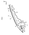
Fig. 1 is a perspective view showing a front portion of a vehicle to which a vehicle hood structure relating to a first embodiment is applied. -
Fig. 2 is a plan view in which the vehicle hood structure relating to the first embodiment is viewed from a vehicle upper side of a hood inner panel. -
Fig. 3 is a vertical sectional view of the vehicle hood structure along line 3-3 inFig. 2 . -
Fig. 4A is a drawing schematically showing a flexing range of a wave-shaped portion of the hood inner panel of the vehicle hood structure shown inFig. 3 . -
Fig. 4B is a drawing schematically showing a flexed state of the wave-shaped portion of the hood inner panel of the vehicle hood structure shown inFig. 4A . -
Fig. 5 is a drawing schematically showing the state of the wave-shaped portion of the hood inner panel and a lock reinforcement of the vehicle hood structure at the time when a collision body collides. -
Fig. 6 is a vertical sectional view showing a vehicle hood structure relating to a second embodiment. -
Fig. 7 is a plan view in which a vehicle hood structure relating to a third embodiment is viewed from a vehicle upper side of a hood inner panel. -
Fig. 8 is a plan view in which a vehicle hood structure relating to a comparative example is viewed from a vehicle upper side of a hood inner panel. -
Fig. 9 is a vertical sectional view of the vehicle hood structure along line 5-5 inFig. 8 . -
Fig. 10A is drawing schematically showing the state of a wave-shaped portion of the hood inner panel and a lock reinforcement at the time when a collision body collides, in the vehicle hood structure shown inFig. 9 . -
Fig. 10B is a drawing schematically showing a flexed state of the wave-shaped portion of the hood inner panel of the vehicle hood structure shown inFig. 10A . - A first embodiment of a vehicle hood structure relating to the present invention is described hereinafter by using
Fig. 1 through Fig. 5 . Note that arrow FR shown appropriately in these drawings indicates the vehicle front side, arrow UP indicates the vehicle upper side, and arrow OUT indicates the vehicle transverse direction outer side. - The front portion of a vehicle, to which the vehicle hood structure relating to the present embodiment is applied, is shown in
Fig. 1 . Further, the structure of the vehicle hood structure relating to the present embodiment is shown inFig. 2 in a state of being viewed from the vehicle upper side of a hood inner panel. Further, the structure of a vicinity of a lock reinforcement of the vehicle hood structure is shown inFig. 3 in a vertical sectional view. As shown inFig. 1 , ahood 12 is provided at the front portion of a vehicle main body of an automobile (vehicle) 10 so as to cover the region above the engine room. At thehood 12, afront end portion 12A can be opened and closed in the vehicle vertical direction with respect to the vehicle main body by a pair of left and right hinge arms (not illustrated) that are provided at the rear end portion in the vehicle longitudinal direction. Ahood lock mechanism 14 is disposed at the vehicle transverse direction central portion at thefront end portion 12A of thehood 12 of the vehicle main body of theautomobile 10. - As shown in
Fig. 2 andFig. 3 , avehicle hood structure 20 of the present embodiment is applied to thehood 12. Thehood 12 has a hoodouter panel 22 that is disposed at the vehicle upper side (the vehicle outer side) along the vehicle transverse direction and the vehicle longitudinal direction, and a hoodinner panel 24 that is disposed at the vehicle lower side of this hoodouter panel 22 along the vehicle transverse direction and the vehicle longitudinal direction. Note that inFig. 2 , the hoodouter panel 22 is illustrated by the two-dot chain lines for easy understanding of the vehicle hood structure of the present embodiment. - The
hood 12 is formed as a closed cross-sectional structure due to aperipheral edge portion 24A of the hoodinner panel 24 and aperipheral edge portion 22A of the hoodouter panel 22 being made integral by hemming processing (seeFig. 3 ). Namely, the hoodouter panel 22 structures the upper surface of thehood 12, and the hoodinner panel 24 structures the lower surface of thehood 12, and the region between the hoodouter panel 22 and the hoodinner panel 24 is hollow. - Plural wave-
shaped portions 40 that extend in the vehicle longitudinal direction are formed in parallel in the vehicle transverse direction in the central region, other than the vicinity of the inner side of theperipheral edge portion 24A, of the hoodinner panel 24. At the plural wave-shapedportions 40,convex portions 40A, that are bent toward the vehicle upper side as seen from the vehicle front surface, andconcave portions 40B, that are bent toward the vehicle lower side, are disposed alternately in the vehicle transverse direction. Namely, the plural wave-shapedportions 40 are included in the "plural beads" of the present invention. Note that the upper surfaces of theconvex portions 40A of the hoodinner panel 24 may be joined by an unillustrated adhesive to the lower surface of the hoodouter panel 22 at predetermined places. - A
lock reinforcement 26, that extends along the vehicle longitudinal direction and the vehicle transverse direction, is disposed at the vehicle lower side of the front portion of the hood inner panel 24 (seeFig. 2 ). In other words, thelock reinforcement 26 is disposed at the vehicle lower side of the front portion of the hoodouter panel 22, and the front end portion of the hoodinner panel 24 is disposed between the hoodouter panel 22 and thelock reinforcement 26. As shown inFig. 3 , thelock reinforcement 26 is made into a shape in which afront end portion 26A is bent in steps toward the vehicle lower side with respect to arear end portion 26B in the vehicle longitudinal direction. A space is formed between the hoodinner panel 24 and thelock reinforcement 26 in the vehicle vertical direction. - A
flange portion 26C that is substantially planar is formed at the end edge of thefront end portion 26A of thelock reinforcement 26. Aplanar portion 24B is formed at the front end portion of the hoodinner panel 24. Theflange portion 26C of thelock reinforcement 26 and theplanar portion 24B of the hoodinner panel 24 are disposed in a planarly-contacting state, and theflange portion 26C and theplanar portion 24B are fastened and fixed bybolts 28 andnuts 30 respectively. Thelock reinforcement 26 is mounted to the vehicle outer side of the hoodinner panel 24 by fixing the nuts 30 by welding in advance to the upper surface of theplanar portion 24B of the hood inner panel 24 (the interior of the hood 12) and inserting thebolts 28 in from the vehicle outer side (the vehicle lower side) of thelock reinforcement 26 and screwing thebolts 28 together with the nuts 30. - As shown in
Fig. 2 , theflange portion 26C at the front end of thelock reinforcement 26 and theplanar portion 24B of the hoodinner panel 24 are fastened and fixed by thebolts 28 and the nuts 30 at plural places in the vehicle transverse direction (five places in the present embodiment) (seeFig. 3 ). Further,end portions 26D at the both vehicle transverse direction sides of thelock reinforcement 26 and planar portions, that are formed at the both vehicle transverse direction sides of the hoodinner panel 24, are disposed in planarly-contacting states. Theend portions 26D of thelock reinforcement 26 and the planar portions of the hoodinner panel 24 are fastened and fixed by thebolts 28 and the nuts 30 at plural places in the vehicle longitudinal direction (three places in the present embodiment). - Namely, predetermined regions of three sides, that are the
flange portion 26C of the front end of thelock reinforcement 26 and theend portions 26D at the both vehicle transverse direction sides, are fastened and fixed to theplanar portion 24B of the front end of the hoodinner panel 24 and to the planar portions at the both vehicle transverse direction sides of the hoodinner panel 24. As shown inFig. 3 , there is no contact between the upper surface of therear end portion 26B of the vehicle transverse direction intermediate portion of thelock reinforcement 26 and the lower surfaces of the plural wave-shaped portions 40 (theconcave portions 40B) of the hoodinner panel 24. In other words, therear end portion 26B of the vehicle transverse direction intermediate portion of thelock reinforcement 26 and the plural wave-shaped portions 40 (theconcave portions 40B) of the hoodinner panel 24 are disposed with agap 46 therebetween in the vehicle vertical direction. Note that thegap 46 in the vehicle vertical direction between therear end portion 26B of the vehicle transverse direction intermediate portion of thelock reinforcement 26 and the plural wave-shaped portions 40 (theconcave portions 40B) of the hoodinner panel 24 is preferably made to be as narrow as possible within the range in which therear end portion 26B of thelock reinforcement 26 and the plural wave-shaped portions 40 (theconcave portions 40B) do not interfere with one another. - As shown in
Fig. 3 , alateral wall portion 26E, that is substantially planar and that is bent toward the vehicle lower side, is formed at thefront end portion 26A of thelock reinforcement 26. Astriker 32, that structures a portion of thehood lock mechanism 14, is mounted to thislateral wall portion 26E. Thestriker 32 is a member that is substantially U-shaped and is disposed along the vehicle longitudinal direction as seen from the vehicle side surface, and hangs-down toward the vehicle main body side from an opening formed in thelateral wall portion 26E of thelock reinforcement 26, and the both end portions thereof are fixed to thelateral wall portion 26E via abase plate 34. By being anchored on a latch portion at the vehicle main body side of thehood lock mechanism 14, thestriker 32 is set in a state of closing thehood 12 at the vehicle main body side. Thelock reinforcement 26 needs strength in order to fix thestriker 32, and is formed as a member whose plate thickness is thicker than the hoodinner panel 24. - As shown in
Fig. 2 andFig. 3 ,front end portions 40C of the plural wave-shapedportions 40 that extend in the vehicle longitudinal direction of the hoodinner panel 24 are positioned further toward the vehicle front side than therear end portion 26B of thelock reinforcement 26. Namely, as shown inFig. 2 , a length A in the vehicle longitudinal direction of the plural wave-shapedportions 40 is formed to be longer than a length B from therear end portion 26B of thelock reinforcement 26 torear end portions 40D of the plural wave-shapedportions 40. The plural wave-shapedportions 40 of the hoodinner panel 24 can flexurally deform toward the vehicle lower side when a collision body 80 (seeFig. 5 ) collides from the vehicle upper side of thehood 12. At this time, due to thefront end portions 40C of the plural wave-shapedportions 40 being extended further toward the vehicle front side than therear end portion 26B of thelock reinforcement 26, stress can be propagated over a wide range of the hoodinner panel 24. -
Beads 42 that extend in the vehicle longitudinal direction are formed at the both vehicle transverse direction sides of the plural wave-shapedportions 40 at the hoodinner panel 24. Thebeads 42 are formed to be shorter than the length A in the vehicle longitudinal direction of the plural wave-shapedportions 40, and are disposed further toward the vehicle rear side than therear end portion 26B of thelock reinforcement 26. Further, thebeads 42 are disposed such that the gaps between thebeads 42 and the wave-shapedportions 40 at the vehicle inner sides widen toward the vehicle rear and outer sides. - Note that, in the present embodiment, the
front end portions 40C of the plural wave-shapedportions 40 that are disposed at the vehicle transverse direction intermediate portion of the hoodinner panel 24 are positioned further toward the vehicle front side than therear end portion 26B of thelock reinforcement 26. However, there may be a structure in which thefront end portions 40C of some of the plural wave-shapedportions 40 are positioned further toward the vehicle front side than therear end portion 26B of thelock reinforcement 26. - The operation and effects of the present embodiment are described next.
- As shown in
Fig. 3 , thefront end portions 40C of the plural wave-shapedportions 40, that are provided at the hoodinner panel 24 and that extend in the vehicle longitudinal direction, are positioned further toward the vehicle front side than therear end portion 26B of thelock reinforcement 26. Due thereto, as shown inFig. 4A , the length A in the vehicle longitudinal direction of the plural wave-shapedportions 40 is long as compared with a case (refer toFig. 9 andFig. 10A ) in which the front end portions of plural wave-shaped portions are disposed further toward the vehicle rear side than therear end portion 26B of thelock reinforcement 26. Due thereto, as shown inFig. 4B , when collision load W is applied, the range in which the plural wave-shapedportions 40 at the hoodinner panel 24 flex is wide in the hood longitudinal direction, and stress is propagated over a wide range of the hoodinner panel 24. - Namely, as shown in
Fig. 5 , when thecollision body 80 collides from the vehicle upper side of thehood 12, the wide region of the plural wave-shapedportions 40 at the hoodinner panel 24 flexes toward the vehicle lower side (the plural wave-shapedportions 40 greatly flex in the hood longitudinal direction), and the flexing range of the hoodinner panel 24 expands. Therefore, due to the inertial mass increasing and the inertial force increasing, the stress propagation range of the hoodinner panel 24 widens, and the energy absorbing performance improves. - Further, the
lock reinforcement 26 is disposed at the vehicle lower side of the hoodinner panel 24, and therear end portion 26B of thelock reinforcement 26 is adjacent to the plural wave-shaped portions 40 (theconcave portions 40B). Therefore, as shown inFig. 5 , due to the plural wave-shapedportions 40 at the hoodinner panel 24 flexing toward the vehicle lower side, the wave-shapedportions 40 hit therear end portion 26B of thelock reinforcement 26, and thelock reinforcement 26 also flexes integrally toward the vehicle lower side, and the load at the time of impact is transmitted to thelock reinforcement 26. Namely, due to the load at the time of impact being distributed to thelock reinforcement 26 as well, the energy absorbing performance can be improved. Due thereto, load input to the head portion of a pedestrian can be reduced, and the pedestrian protecting performance can be ensured. - Further, by disposing the
rear end portion 26B of thelock reinforcement 26 and the plural wave-shaped portions 40 (theconcave portions 40B) of the hoodinner panel 24 with thegap 46 therebetween in the vertical direction, interference between therear end portion 26B of thelock reinforcement 26 and the hoodinner panel 24 is suppressed, and the NV performance can be improved. - A
hood 100 that has avehicle hood structure 102 relating to a comparative example is illustrated inFig. 8 through Fig. 10B . - As shown in
Fig. 8 , three openingportions 106 that are substantially rectangular are formed in a hoodinner panel 104 that structures thehood 100, at predetermined intervals in the vehicle transverse direction.Frame portions 104A that are extended along the vehicle longitudinal direction are provided between the adjacent openingportions 106.Beads 104B, that project-out toward the vehicle upper side as seen from the vehicle front surface, are provided at theframe portions 104A along the vehicle longitudinal direction (longitudinal direction). As shown inFig. 9 , avertical wall portion 104C that is bent toward the vehicle lower side is formed at the vehicle front side of thebead 104B at the hoodinner panel 104. A lateral wall portion (weak portion) 104D, that is extended in the vehicle longitudinal direction and the vehicle transverse direction, is formed further toward the vehicle front side than thevertical wall portion 104C. - A
lock reinforcement 108 is disposed at the vehicle lower side of thelateral wall portion 104D of the hoodinner panel 104. Afront end portion 108A of thelock reinforcement 108 is fastened and fixed by unillustrated fasteners to aplanar portion 104E that is formed at the front end portion of the hood inner panel 104 (further toward the vehicle front side than thelateral wall portion 104D). As seen from the vehicle side surface, the front end portions of the plural (two in this comparative example)beads 104B of the hoodinner panel 104 are positioned further toward the vehicle rear side than arear end portion 108B of thelock reinforcement 108. Namely, a length C in the vehicle longitudinal direction of theplural beads 104B is formed to be shorter than a length D from therear end portion 26B of thelock reinforcement 26 to the rear end portions of theplural beads 104B (seeFig. 8 ). - In this
vehicle hood structure 102, as compared with the length A in the vehicle longitudinal direction of the plural wave-shapedportions 40 of thevehicle hood structure 20 of the present embodiment (seeFig. 2 ), the length C in the vehicle longitudinal direction of theplural beads 104B of the hoodinner panel 104 is short, and the range in which theplural beads 104B flex toward the vehicle lower side is narrow. - Namely, as shown in
Fig. 10A and Fig. 10B , when thecollision body 80 collides from the vehicle upper side of thehood 100, the stress propagation range of the hoodinner panel 104 with respect to the impact of thecollision body 80 is narrow. Further, even if theplural beads 104B of the hoodinner panel 104 flex toward the vehicle lower side, thevertical wall portion 104C at the vehicle front sides of theplural beads 104B is hard and therefore does not flex, and thevertical wall portion 104C becomes a supporting point, and thebeads 104B are flexed toward the vehicle lower side, and the lateral wall portion (the weak portion) 104D, that is further toward the vehicle front side than thevertical wall portion 104C, is flexed in a substantial S-shape toward the vehicle upper side. Therefore, the hoodinner panel 104 does not contact thelock reinforcement 26 that is positioned further toward the vehicle lower side than the hoodinner panel 104, and the impact load is not transmitted to thelock reinforcement 26. - In contrast, in the
vehicle hood structure 20 of the present embodiment, as shown inFig. 2 andFig. 3 and the like, due to thefront end portions 40C of the plural wave-shapedportions 40 at the hoodinner panel 24 being extended further toward the vehicle front side than therear end portion 26B of thelock reinforcement 26, the stress propagation range of the hoodinner panel 24 is broad as compared with thevehicle hood structure 102 of the comparative example. Therefore, when thecollision body 80 collides, due to stress being propagated in the wide range of the plural wave-shapedportions 40 of the hoodinner panel 24, the energy absorbing performance improves. Further, in thevehicle hood structure 20 of the present embodiment, the amount of displacement toward the vehicle lower side of the hoodinner panel 24 can be made to be small as compared with the amount of displacement of the hoodinner panel 104 of thevehicle hood structure 102 of the comparative example, when the load W of the same magnitude is applied to thehood 12. Therefore, more energy can be absorbed by a short stroke. Moreover, due to the plural wave-shapedportions 40 of the hoodinner panel 24 flexing toward the vehicle lower side and abutting therear end portion 26B of thelock reinforcement 26, the impact load is transmitted to thelock reinforcement 26, and the energy absorbing performance can be improved even more. - A second embodiment of the vehicle hood structure relating to the present invention is described next by using
Fig. 6 . Note that structural portions that are the same as the above-described first embodiment are denoted by the same numbers, and description thereof is omitted. - A
hood 50, to which avehicle hood structure 52 of the present embodiment is applied, is shown inFig. 6 . As shown in this drawing, alock reinforcement 54 is disposed at the vehicle lower side of the hoodinner panel 24 that structures thehood 50. Arear end portion 54A of thelock reinforcement 54 and the plural wave-shaped portions 40 (theconcave portions 40B) that are formed at the hoodinner panel 24 are disposed so as to not contact in the vertical direction. - A
gap filling material 56, that is sheet-shaped and is for mitigating interference between therear end portion 54A of thelock reinforcement 54 and the plural wave-shapedportions 40 of the hoodinner panel 24, is interposed in the gap between therear end portion 54A of thelock reinforcement 54 and theconcave portions 40B of the plural wave-shapedportions 40. In the present embodiment, thegap filling material 56 is formed of a foamed resin. Note that the material of thegap filling material 56 is not limited to this, and may be an interference mitigating material formed from a non-woven fabric, fibers, or the like. Thegap filling material 56 is fixed to the upper surface of therear end portion 54A of thelock reinforcement 54 by an adhesive or the like. - In this
vehicle hood structure 52, due to thegap filling material 56 that is made of a foamed resin being disposed in the gap between therear end portion 54A of thelock reinforcement 54 and theconcave portions 40B of the plural wave-shapedportions 40, interference between therear end portion 54A of thelock reinforcement 54 and the plural wave-shapedportions 40 of the hoodinner panel 24 at the time of traveling of the vehicle is mitigated, and the NV performance can be improved. - A third embodiment of the vehicle hood structure relating to the present invention is described next by using
Fig. 7 . Note that structural portions that are the same as the above-described first embodiment and second embodiment are denoted by the same numbers, and description thereof is omitted. - A
hood 60, to which avehicle hood structure 62 of the present embodiment is applied, is shown inFig. 7 . Alock reinforcement 68 is disposed at the vehicle lower side of the front end portion of a hoodinner panel 64 that structures thehood 60. Two openingportions 66, that are substantially rectangular and that are long in the vehicle longitudinal direction, are formed at a predetermined interval in the vehicle transverse direction central portion at the hoodinner panel 64. Further, openingportions 67, that are substantially rectangular and whose lengths in the vehicle longitudinal direction are shorter than the openingportions 66, are formed in the hoodinner panel 64 at the vehicle transverse direction both sides of the rear portions of the two openingportions 66.Frame portions portions 66 and between theadjacent opening portion 66 andopening portion 67. - A
bead 74, that is substantially hat-shaped in cross-section and that projects-out toward the vehicle lower side as seen from the vehicle front surface, is formed along the vehicle longitudinal direction at theframe portion 64A at the vehicle transverse direction central portion of the hoodinner panel 64. Similarly, thebeads 74, that are substantially hat-shaped in cross-section and that project-out toward the vehicle lower side as seen from the vehicle front surface, are formed along the vehicle longitudinal direction at theframe portions 64B at the vehicle transverse direction both sides of the hoodinner panel 64 and at the wall portions at the vehicle front sides thereof. Namely, the threebeads 74 that respectively extend in the vehicle longitudinal direction are disposed in parallel in the vehicle transverse direction. The threebeads 74 are formed such that the lengths thereof in the vehicle longitudinal direction are substantially the same, andfront end portions 74A of thebeads 74 are positioned further toward the vehicle front side than arear end portion 68B of thelock reinforcement 68. Afront end portion 68A of thelock reinforcement 68 is fastened and fixed to the front end portion of the hoodinner panel 64. There is no contact between the upper surface of therear end portion 68B of thelock reinforcement 68 and the lower surfaces of the beads 74 (therear end portion 68B of thelock reinforcement 68 and thebeads 74 are disposed with a gap therebetween in the vertical direction). - In this
vehicle hood structure 62, by extending thefront end portions 74A of theplural beads 74 at the hoodinner panel 64 further toward the vehicle front side than therear end portion 68B of thelock reinforcement 68, the range in which theplural beads 74 flex is wide and the stress propagation range of the hoodinner panel 64 is wide as compared with thevehicle hood structure 102 of the comparative example (seeFig. 9 and the like). Therefore, when a collision body (not illustrated) collides from the upper side of thehood 60, the energy absorbing performance is improved due to theplural beads 74 flexing toward the vehicle lower side and stress being propagated in the wide range of the hoodinner panel 64. Moreover, due to theplural beads 74 of the hoodinner panel 64 flexing toward the vehicle lower side and abutting therear end portion 68B of thelock reinforcement 68, the impact load is transmitted to thelock reinforcement 68, and the energy absorbing performance can be improved even more. - Note that the shape and the number of the plural wave-shaped
portions 40 in the first embodiment and the second embodiment are not limited to the above-described embodiments, and can be changed. Further, the shape and the number of theplural beads 74 of the third embodiment are not limited to the above-described embodiment, and can be changed. - Further, in the first embodiment and the second embodiment, the
front end portions 40C of the plural wave-shapedportions 40 are positioned further toward the vehicle front side than the rear end portion of the lock reinforcement, but the present invention is not limited to this. There may be a structure in which thefront end portion 40C of at least one of the wave-shapedportions 40 is positioned further toward the vehicle front side than the rear end portion of the lock reinforcement. - Further, in the third embodiment, the
front end portions 74A of theplural beads 74 are positioned further toward the vehicle front side than the rear end portion of the lock reinforcement, but the present invention is not limited to this. There may be a structure in which thefront end portion 74A of at least one of thebeads 74 is positioned further toward the vehicle front side than the rear end portion of the lock reinforcement. - Further, the plural beads of the first embodiment through the third embodiment (including the plural wave-shaped portions 40) may be shapes at which the intervals between the beads gradually widen toward the vehicle rear side (fan shapes), or, only the beads at the vehicle transverse direction outermost sides, or two to three beads including the beads at the vehicle transverse direction outermost sides, may be tilted obliquely.
Claims (5)
- A vehicle hood structure comprising:a hood outer panel that structures a hood outer plate;a lock reinforcement that is provided at a lower side of a vehicle front portion of the hood outer panel, and that supports a hood lock; anda hood inner panel whose front end portion is disposed between the hood outer panel and the lock reinforcement, and that structures a hood inner plate, a plurality of beads that respectively extend in a vehicle longitudinal direction being provided in parallel in a vehicle transverse direction at the hood inner panel, and the hood inner panel being disposed such that a front end portion of at least one of the beads is positioned further toward a vehicle front side than a rear end portion of the lock reinforcement.
- The vehicle hood structure of Claim 1, wherein the plurality of beads are structured from a plurality of wave-shaped portions.
- The vehicle hood structure of Claim 1, wherein the beads are provided at a plurality of frame portions that are extended along the vehicle longitudinal direction, between a plurality of opening portions that are provided in the hood inner panel.
- The vehicle hood structure of any one of Claim 1 through Claim 3, wherein a front portion of the hood inner panel and the rear end portion of the lock reinforcement are disposed with a gap therebetween in a vertical direction.
- The vehicle hood structure of Claim 4, wherein, between the front portion of the hood inner panel and the rear end portion of the lock reinforcement, a gap filling material for mitigating interference between the two is interposed.
Applications Claiming Priority (1)
| Application Number | Priority Date | Filing Date | Title |
|---|---|---|---|
| PCT/JP2011/061457 WO2012157100A1 (en) | 2011-05-18 | 2011-05-18 | Hood structure for vehicle |
Publications (3)
| Publication Number | Publication Date |
|---|---|
| EP2711271A4 EP2711271A4 (en) | 2014-03-26 |
| EP2711271A1 true EP2711271A1 (en) | 2014-03-26 |
| EP2711271B1 EP2711271B1 (en) | 2015-01-14 |
Family
ID=47176463
Family Applications (1)
| Application Number | Title | Priority Date | Filing Date |
|---|---|---|---|
| EP11865774.1A Not-in-force EP2711271B1 (en) | 2011-05-18 | 2011-05-18 | Vehicle hood structure |
Country Status (5)
| Country | Link |
|---|---|
| US (1) | US9027987B2 (en) |
| EP (1) | EP2711271B1 (en) |
| JP (1) | JP5556959B2 (en) |
| CN (1) | CN103517847B (en) |
| WO (1) | WO2012157100A1 (en) |
Cited By (2)
| Publication number | Priority date | Publication date | Assignee | Title |
|---|---|---|---|---|
| EP2982575A1 (en) * | 2014-08-04 | 2016-02-10 | Toyota Jidosha Kabushiki Kaisha | Vehicle hood structure |
| EP2955085A4 (en) * | 2013-02-08 | 2016-10-12 | Toyota Tekko Kk | Vehicle hood structure |
Families Citing this family (20)
| Publication number | Priority date | Publication date | Assignee | Title |
|---|---|---|---|---|
| JP2014201143A (en) * | 2013-04-03 | 2014-10-27 | トヨタ自動車株式会社 | Fiber-reinforced resin hood panel |
| JP5835279B2 (en) * | 2013-06-28 | 2015-12-24 | トヨタ自動車株式会社 | Vehicle hood structure |
| DE102013014203A1 (en) * | 2013-08-26 | 2015-02-26 | GM Global Technology Operations LLC (n. d. Ges. d. Staates Delaware) | Front hood for a motor vehicle |
| DE102014003199A1 (en) * | 2014-03-04 | 2015-09-10 | GM Global Technology Operations LLC (n. d. Ges. d. Staates Delaware) | Front hood for a motor vehicle |
| JP6258108B2 (en) * | 2014-04-09 | 2018-01-10 | 株式会社神戸製鋼所 | Vehicle hood |
| US9393922B2 (en) * | 2014-05-23 | 2016-07-19 | Google Inc. | Devices and methods for an energy-absorbing end of a vehicle |
| US9248866B2 (en) * | 2014-06-13 | 2016-02-02 | Toyota Motor Engineering & Manufacturing North America, Inc. | Hood assembly |
| US9868472B2 (en) * | 2014-09-19 | 2018-01-16 | Mazda Motor Corporation | Bonnet structure of automotive vehicle |
| JP6137139B2 (en) * | 2014-11-21 | 2017-05-31 | トヨタ自動車株式会社 | Vehicle panel structure |
| JP6233327B2 (en) * | 2015-02-05 | 2017-11-22 | トヨタ自動車株式会社 | VEHICLE PANEL STRUCTURE AND METHOD FOR MANUFACTURING VEHICLE PANEL STRUCTURE |
| JP6718726B2 (en) * | 2016-03-31 | 2020-07-08 | 株式会社神戸製鋼所 | Vehicle hood |
| JP6708070B2 (en) * | 2016-09-09 | 2020-06-10 | 三菱自動車工業株式会社 | Vehicle hood |
| JP6764453B2 (en) * | 2018-09-27 | 2020-09-30 | 本田技研工業株式会社 | Body front structure |
| US11884332B2 (en) * | 2019-01-10 | 2024-01-30 | Nippon Steel Corporation | Automobile hood |
| CN113316537B (en) * | 2019-01-10 | 2023-08-01 | 日本制铁株式会社 | car hood |
| US11286005B2 (en) * | 2019-09-03 | 2022-03-29 | Honda Motor Co., Ltd. | Hood frame reinforcement for deflection mitigation |
| CN115335277B (en) * | 2020-03-30 | 2024-09-27 | 日本制铁株式会社 | Car hood |
| JP7360628B2 (en) * | 2020-03-31 | 2023-10-13 | マツダ株式会社 | Vehicle front body structure |
| JP7338614B2 (en) * | 2020-11-24 | 2023-09-05 | トヨタ自動車株式会社 | vehicle |
| US20250346298A1 (en) * | 2024-05-13 | 2025-11-13 | Ford Global Technologies, Llc | Vehicle hood assembly having a waterfall region supporting a latch reinforcement |
Family Cites Families (10)
| Publication number | Priority date | Publication date | Assignee | Title |
|---|---|---|---|---|
| KR100955550B1 (en) | 2000-12-13 | 2010-04-30 | 가부시키가이샤 고베 세이코쇼 | Panel structure for body hood |
| JP4300908B2 (en) | 2003-07-04 | 2009-07-22 | トヨタ自動車株式会社 | Vehicle hood structure |
| EP1829756B1 (en) * | 2003-07-01 | 2012-12-12 | Toyota Jidosha Kabushiki Kaisha | Vehicular hood structure and vehicle body front portion structure |
| JP2005075176A (en) * | 2003-09-01 | 2005-03-24 | Toyota Motor Corp | Vehicle hood structure |
| JP2005075163A (en) | 2003-09-01 | 2005-03-24 | Toyota Motor Corp | Vehicle hood structure |
| JP2007223414A (en) * | 2006-02-22 | 2007-09-06 | Toyota Motor Corp | Vehicle hood structure |
| JP4719039B2 (en) * | 2006-03-15 | 2011-07-06 | 株式会社神戸製鋼所 | Automotive hood |
| JP2008110668A (en) * | 2006-10-30 | 2008-05-15 | Kanto Auto Works Ltd | Vehicle hood structure |
| BRPI0808432A2 (en) * | 2007-03-07 | 2014-07-29 | Alcoa Inc | SAFE PEDESTRIAN AUTOMOTIVE CAP WITH REINFORCEMENT FOAM |
| JP4685906B2 (en) | 2008-07-22 | 2011-05-18 | トヨタ自動車株式会社 | Vehicle hood structure |
-
2011
- 2011-05-18 JP JP2013514929A patent/JP5556959B2/en not_active Expired - Fee Related
- 2011-05-18 US US14/116,677 patent/US9027987B2/en not_active Expired - Fee Related
- 2011-05-18 EP EP11865774.1A patent/EP2711271B1/en not_active Not-in-force
- 2011-05-18 CN CN201180070831.0A patent/CN103517847B/en not_active Expired - Fee Related
- 2011-05-18 WO PCT/JP2011/061457 patent/WO2012157100A1/en not_active Ceased
Cited By (2)
| Publication number | Priority date | Publication date | Assignee | Title |
|---|---|---|---|---|
| EP2955085A4 (en) * | 2013-02-08 | 2016-10-12 | Toyota Tekko Kk | Vehicle hood structure |
| EP2982575A1 (en) * | 2014-08-04 | 2016-02-10 | Toyota Jidosha Kabushiki Kaisha | Vehicle hood structure |
Also Published As
| Publication number | Publication date |
|---|---|
| CN103517847B (en) | 2015-07-01 |
| CN103517847A (en) | 2014-01-15 |
| WO2012157100A1 (en) | 2012-11-22 |
| US9027987B2 (en) | 2015-05-12 |
| EP2711271A4 (en) | 2014-03-26 |
| JP5556959B2 (en) | 2014-07-23 |
| JPWO2012157100A1 (en) | 2014-07-31 |
| EP2711271B1 (en) | 2015-01-14 |
| US20140062142A1 (en) | 2014-03-06 |
Similar Documents
| Publication | Publication Date | Title |
|---|---|---|
| EP2711271B1 (en) | Vehicle hood structure | |
| CN102695643B (en) | Hood structure of vehicle | |
| JP6156488B2 (en) | Body structure | |
| US8033592B2 (en) | Door assembly and method for a vehicle | |
| KR100676948B1 (en) | Vehicle hood structure | |
| KR101781089B1 (en) | Vehicle body front structure of a vehicle | |
| CN111776077B (en) | Front pillar structure for vehicle | |
| CN104903130B (en) | Front body structure of the vehicle | |
| US8807634B2 (en) | Cowl-top cover crossmember having stepped portions | |
| CN109895869B (en) | Body floor structure | |
| KR20080052754A (en) | Cowl side part reinforcement structure of vehicle | |
| JP4978253B2 (en) | Fender cover structure and front body structure | |
| JP5692033B2 (en) | Vehicle hood structure | |
| CN108349547B (en) | The front body structure of the car | |
| WO2015119106A1 (en) | Vehicle-body front structure | |
| WO2008066041A1 (en) | Front structure for vehicle | |
| US9440680B2 (en) | Vehicle cowl structure | |
| KR20250028430A (en) | Panel set | |
| JP7103439B2 (en) | Side structure of automobiles and automobiles | |
| JP2009184527A (en) | Pillar reinforcement structure | |
| CN113173139A (en) | Vehicle body structure of vehicle | |
| JP5772522B2 (en) | Vehicle hood structure | |
| KR102923218B1 (en) | Dash panel assembly | |
| JP2004249868A (en) | Reinforcing member structure | |
| JP2011178218A (en) | Front pillar structure |
Legal Events
| Date | Code | Title | Description |
|---|---|---|---|
| PUAI | Public reference made under article 153(3) epc to a published international application that has entered the european phase |
Free format text: ORIGINAL CODE: 0009012 |
|
| 17P | Request for examination filed |
Effective date: 20131116 |
|
| A4 | Supplementary search report drawn up and despatched |
Effective date: 20140226 |
|
| AK | Designated contracting states |
Kind code of ref document: A1 Designated state(s): AL AT BE BG CH CY CZ DE DK EE ES FI FR GB GR HR HU IE IS IT LI LT LU LV MC MK MT NL NO PL PT RO RS SE SI SK SM TR |
|
| RIC1 | Information provided on ipc code assigned before grant |
Ipc: B62D 25/10 20060101AFI20140313BHEP Ipc: B60R 21/34 20110101ALI20140313BHEP |
|
| RIN1 | Information on inventor provided before grant (corrected) |
Inventor name: IKEDA, KOKI Inventor name: IZUHARA, TSUYOSHI Inventor name: YONEZAWA, SEIHO |
|
| DAX | Request for extension of the european patent (deleted) | ||
| GRAP | Despatch of communication of intention to grant a patent |
Free format text: ORIGINAL CODE: EPIDOSNIGR1 |
|
| INTG | Intention to grant announced |
Effective date: 20140905 |
|
| GRAS | Grant fee paid |
Free format text: ORIGINAL CODE: EPIDOSNIGR3 |
|
| GRAA | (expected) grant |
Free format text: ORIGINAL CODE: 0009210 |
|
| AK | Designated contracting states |
Kind code of ref document: B1 Designated state(s): AL AT BE BG CH CY CZ DE DK EE ES FI FR GB GR HR HU IE IS IT LI LT LU LV MC MK MT NL NO PL PT RO RS SE SI SK SM TR |
|
| REG | Reference to a national code |
Ref country code: GB Ref legal event code: FG4D |
|
| REG | Reference to a national code |
Ref country code: CH Ref legal event code: EP |
|
| REG | Reference to a national code |
Ref country code: IE Ref legal event code: FG4D |
|
| REG | Reference to a national code |
Ref country code: AT Ref legal event code: REF Ref document number: 706869 Country of ref document: AT Kind code of ref document: T Effective date: 20150215 |
|
| REG | Reference to a national code |
Ref country code: DE Ref legal event code: R096 Ref document number: 602011013257 Country of ref document: DE Effective date: 20150226 |
|
| REG | Reference to a national code |
Ref country code: DE Ref legal event code: R084 Ref document number: 602011013257 Country of ref document: DE |
|
| REG | Reference to a national code |
Ref country code: DE Ref legal event code: R084 Ref document number: 602011013257 Country of ref document: DE Effective date: 20150317 |
|
| REG | Reference to a national code |
Ref country code: NL Ref legal event code: VDEP Effective date: 20150114 |
|
| REG | Reference to a national code |
Ref country code: AT Ref legal event code: MK05 Ref document number: 706869 Country of ref document: AT Kind code of ref document: T Effective date: 20150114 |
|
| REG | Reference to a national code |
Ref country code: LT Ref legal event code: MG4D |
|
| PG25 | Lapsed in a contracting state [announced via postgrant information from national office to epo] |
Ref country code: NO Free format text: LAPSE BECAUSE OF FAILURE TO SUBMIT A TRANSLATION OF THE DESCRIPTION OR TO PAY THE FEE WITHIN THE PRESCRIBED TIME-LIMIT Effective date: 20150414 Ref country code: LT Free format text: LAPSE BECAUSE OF FAILURE TO SUBMIT A TRANSLATION OF THE DESCRIPTION OR TO PAY THE FEE WITHIN THE PRESCRIBED TIME-LIMIT Effective date: 20150114 Ref country code: FI Free format text: LAPSE BECAUSE OF FAILURE TO SUBMIT A TRANSLATION OF THE DESCRIPTION OR TO PAY THE FEE WITHIN THE PRESCRIBED TIME-LIMIT Effective date: 20150114 Ref country code: ES Free format text: LAPSE BECAUSE OF FAILURE TO SUBMIT A TRANSLATION OF THE DESCRIPTION OR TO PAY THE FEE WITHIN THE PRESCRIBED TIME-LIMIT Effective date: 20150114 Ref country code: BG Free format text: LAPSE BECAUSE OF FAILURE TO SUBMIT A TRANSLATION OF THE DESCRIPTION OR TO PAY THE FEE WITHIN THE PRESCRIBED TIME-LIMIT Effective date: 20150414 Ref country code: SE Free format text: LAPSE BECAUSE OF FAILURE TO SUBMIT A TRANSLATION OF THE DESCRIPTION OR TO PAY THE FEE WITHIN THE PRESCRIBED TIME-LIMIT Effective date: 20150114 Ref country code: HR Free format text: LAPSE BECAUSE OF FAILURE TO SUBMIT A TRANSLATION OF THE DESCRIPTION OR TO PAY THE FEE WITHIN THE PRESCRIBED TIME-LIMIT Effective date: 20150114 |
|
| PG25 | Lapsed in a contracting state [announced via postgrant information from national office to epo] |
Ref country code: NL Free format text: LAPSE BECAUSE OF FAILURE TO SUBMIT A TRANSLATION OF THE DESCRIPTION OR TO PAY THE FEE WITHIN THE PRESCRIBED TIME-LIMIT Effective date: 20150114 Ref country code: LV Free format text: LAPSE BECAUSE OF FAILURE TO SUBMIT A TRANSLATION OF THE DESCRIPTION OR TO PAY THE FEE WITHIN THE PRESCRIBED TIME-LIMIT Effective date: 20150114 Ref country code: IS Free format text: LAPSE BECAUSE OF FAILURE TO SUBMIT A TRANSLATION OF THE DESCRIPTION OR TO PAY THE FEE WITHIN THE PRESCRIBED TIME-LIMIT Effective date: 20150514 Ref country code: GR Free format text: LAPSE BECAUSE OF FAILURE TO SUBMIT A TRANSLATION OF THE DESCRIPTION OR TO PAY THE FEE WITHIN THE PRESCRIBED TIME-LIMIT Effective date: 20150415 Ref country code: AT Free format text: LAPSE BECAUSE OF FAILURE TO SUBMIT A TRANSLATION OF THE DESCRIPTION OR TO PAY THE FEE WITHIN THE PRESCRIBED TIME-LIMIT Effective date: 20150114 Ref country code: RS Free format text: LAPSE BECAUSE OF FAILURE TO SUBMIT A TRANSLATION OF THE DESCRIPTION OR TO PAY THE FEE WITHIN THE PRESCRIBED TIME-LIMIT Effective date: 20150114 Ref country code: PL Free format text: LAPSE BECAUSE OF FAILURE TO SUBMIT A TRANSLATION OF THE DESCRIPTION OR TO PAY THE FEE WITHIN THE PRESCRIBED TIME-LIMIT Effective date: 20150114 |
|
| REG | Reference to a national code |
Ref country code: DE Ref legal event code: R097 Ref document number: 602011013257 Country of ref document: DE |
|
| PG25 | Lapsed in a contracting state [announced via postgrant information from national office to epo] |
Ref country code: RO Free format text: LAPSE BECAUSE OF FAILURE TO SUBMIT A TRANSLATION OF THE DESCRIPTION OR TO PAY THE FEE WITHIN THE PRESCRIBED TIME-LIMIT Effective date: 20150114 Ref country code: SK Free format text: LAPSE BECAUSE OF FAILURE TO SUBMIT A TRANSLATION OF THE DESCRIPTION OR TO PAY THE FEE WITHIN THE PRESCRIBED TIME-LIMIT Effective date: 20150114 Ref country code: EE Free format text: LAPSE BECAUSE OF FAILURE TO SUBMIT A TRANSLATION OF THE DESCRIPTION OR TO PAY THE FEE WITHIN THE PRESCRIBED TIME-LIMIT Effective date: 20150114 Ref country code: DK Free format text: LAPSE BECAUSE OF FAILURE TO SUBMIT A TRANSLATION OF THE DESCRIPTION OR TO PAY THE FEE WITHIN THE PRESCRIBED TIME-LIMIT Effective date: 20150114 Ref country code: CZ Free format text: LAPSE BECAUSE OF FAILURE TO SUBMIT A TRANSLATION OF THE DESCRIPTION OR TO PAY THE FEE WITHIN THE PRESCRIBED TIME-LIMIT Effective date: 20150114 |
|
| PLBE | No opposition filed within time limit |
Free format text: ORIGINAL CODE: 0009261 |
|
| STAA | Information on the status of an ep patent application or granted ep patent |
Free format text: STATUS: NO OPPOSITION FILED WITHIN TIME LIMIT |
|
| 26N | No opposition filed |
Effective date: 20151015 |
|
| PG25 | Lapsed in a contracting state [announced via postgrant information from national office to epo] |
Ref country code: IT Free format text: LAPSE BECAUSE OF FAILURE TO SUBMIT A TRANSLATION OF THE DESCRIPTION OR TO PAY THE FEE WITHIN THE PRESCRIBED TIME-LIMIT Effective date: 20150114 |
|
| REG | Reference to a national code |
Ref country code: CH Ref legal event code: PL |
|
| GBPC | Gb: european patent ceased through non-payment of renewal fee |
Effective date: 20150518 |
|
| PG25 | Lapsed in a contracting state [announced via postgrant information from national office to epo] |
Ref country code: MC Free format text: LAPSE BECAUSE OF FAILURE TO SUBMIT A TRANSLATION OF THE DESCRIPTION OR TO PAY THE FEE WITHIN THE PRESCRIBED TIME-LIMIT Effective date: 20150114 Ref country code: CH Free format text: LAPSE BECAUSE OF NON-PAYMENT OF DUE FEES Effective date: 20150531 Ref country code: LU Free format text: LAPSE BECAUSE OF FAILURE TO SUBMIT A TRANSLATION OF THE DESCRIPTION OR TO PAY THE FEE WITHIN THE PRESCRIBED TIME-LIMIT Effective date: 20150518 Ref country code: LI Free format text: LAPSE BECAUSE OF NON-PAYMENT OF DUE FEES Effective date: 20150531 |
|
| REG | Reference to a national code |
Ref country code: IE Ref legal event code: MM4A |
|
| REG | Reference to a national code |
Ref country code: FR Ref legal event code: ST Effective date: 20160129 |
|
| PG25 | Lapsed in a contracting state [announced via postgrant information from national office to epo] |
Ref country code: SI Free format text: LAPSE BECAUSE OF FAILURE TO SUBMIT A TRANSLATION OF THE DESCRIPTION OR TO PAY THE FEE WITHIN THE PRESCRIBED TIME-LIMIT Effective date: 20150114 |
|
| PG25 | Lapsed in a contracting state [announced via postgrant information from national office to epo] |
Ref country code: IE Free format text: LAPSE BECAUSE OF NON-PAYMENT OF DUE FEES Effective date: 20150518 Ref country code: GB Free format text: LAPSE BECAUSE OF NON-PAYMENT OF DUE FEES Effective date: 20150518 |
|
| PG25 | Lapsed in a contracting state [announced via postgrant information from national office to epo] |
Ref country code: FR Free format text: LAPSE BECAUSE OF NON-PAYMENT OF DUE FEES Effective date: 20150601 Ref country code: BE Free format text: LAPSE BECAUSE OF FAILURE TO SUBMIT A TRANSLATION OF THE DESCRIPTION OR TO PAY THE FEE WITHIN THE PRESCRIBED TIME-LIMIT Effective date: 20150114 |
|
| PG25 | Lapsed in a contracting state [announced via postgrant information from national office to epo] |
Ref country code: MT Free format text: LAPSE BECAUSE OF FAILURE TO SUBMIT A TRANSLATION OF THE DESCRIPTION OR TO PAY THE FEE WITHIN THE PRESCRIBED TIME-LIMIT Effective date: 20150114 |
|
| PG25 | Lapsed in a contracting state [announced via postgrant information from national office to epo] |
Ref country code: HU Free format text: LAPSE BECAUSE OF FAILURE TO SUBMIT A TRANSLATION OF THE DESCRIPTION OR TO PAY THE FEE WITHIN THE PRESCRIBED TIME-LIMIT; INVALID AB INITIO Effective date: 20110518 Ref country code: SM Free format text: LAPSE BECAUSE OF FAILURE TO SUBMIT A TRANSLATION OF THE DESCRIPTION OR TO PAY THE FEE WITHIN THE PRESCRIBED TIME-LIMIT Effective date: 20150114 |
|
| PG25 | Lapsed in a contracting state [announced via postgrant information from national office to epo] |
Ref country code: CY Free format text: LAPSE BECAUSE OF FAILURE TO SUBMIT A TRANSLATION OF THE DESCRIPTION OR TO PAY THE FEE WITHIN THE PRESCRIBED TIME-LIMIT Effective date: 20150114 |
|
| PG25 | Lapsed in a contracting state [announced via postgrant information from national office to epo] |
Ref country code: TR Free format text: LAPSE BECAUSE OF FAILURE TO SUBMIT A TRANSLATION OF THE DESCRIPTION OR TO PAY THE FEE WITHIN THE PRESCRIBED TIME-LIMIT Effective date: 20150114 |
|
| PG25 | Lapsed in a contracting state [announced via postgrant information from national office to epo] |
Ref country code: PT Free format text: LAPSE BECAUSE OF FAILURE TO SUBMIT A TRANSLATION OF THE DESCRIPTION OR TO PAY THE FEE WITHIN THE PRESCRIBED TIME-LIMIT Effective date: 20150114 Ref country code: MK Free format text: LAPSE BECAUSE OF FAILURE TO SUBMIT A TRANSLATION OF THE DESCRIPTION OR TO PAY THE FEE WITHIN THE PRESCRIBED TIME-LIMIT Effective date: 20150114 |
|
| PG25 | Lapsed in a contracting state [announced via postgrant information from national office to epo] |
Ref country code: AL Free format text: LAPSE BECAUSE OF FAILURE TO SUBMIT A TRANSLATION OF THE DESCRIPTION OR TO PAY THE FEE WITHIN THE PRESCRIBED TIME-LIMIT Effective date: 20150114 |
|
| PGFP | Annual fee paid to national office [announced via postgrant information from national office to epo] |
Ref country code: DE Payment date: 20210420 Year of fee payment: 11 |
|
| REG | Reference to a national code |
Ref country code: DE Ref legal event code: R119 Ref document number: 602011013257 Country of ref document: DE |
|
| PG25 | Lapsed in a contracting state [announced via postgrant information from national office to epo] |
Ref country code: DE Free format text: LAPSE BECAUSE OF NON-PAYMENT OF DUE FEES Effective date: 20221201 |