EP2627541B1 - Gas generator and airbag module - Google Patents
Gas generator and airbag module Download PDFInfo
- Publication number
- EP2627541B1 EP2627541B1 EP11813864.3A EP11813864A EP2627541B1 EP 2627541 B1 EP2627541 B1 EP 2627541B1 EP 11813864 A EP11813864 A EP 11813864A EP 2627541 B1 EP2627541 B1 EP 2627541B1
- Authority
- EP
- European Patent Office
- Prior art keywords
- combustion chamber
- fuel canister
- sleeve
- inflator
- chamber sleeve
- Prior art date
- Legal status (The legal status is an assumption and is not a legal conclusion. Google has not performed a legal analysis and makes no representation as to the accuracy of the status listed.)
- Active
Links
Images


Classifications
-
- B—PERFORMING OPERATIONS; TRANSPORTING
- B60—VEHICLES IN GENERAL
- B60R—VEHICLES, VEHICLE FITTINGS, OR VEHICLE PARTS, NOT OTHERWISE PROVIDED FOR
- B60R21/00—Arrangements or fittings on vehicles for protecting or preventing injuries to occupants or pedestrians in case of accidents or other traffic risks
- B60R21/02—Occupant safety arrangements or fittings, e.g. crash pads
- B60R21/16—Inflatable occupant restraints or confinements designed to inflate upon impact or impending impact, e.g. air bags
- B60R21/26—Inflatable occupant restraints or confinements designed to inflate upon impact or impending impact, e.g. air bags characterised by the inflation fluid source or means to control inflation fluid flow
- B60R21/261—Inflatable occupant restraints or confinements designed to inflate upon impact or impending impact, e.g. air bags characterised by the inflation fluid source or means to control inflation fluid flow with means other than bag structure to diffuse or guide inflation fluid
-
- B—PERFORMING OPERATIONS; TRANSPORTING
- B60—VEHICLES IN GENERAL
- B60R—VEHICLES, VEHICLE FITTINGS, OR VEHICLE PARTS, NOT OTHERWISE PROVIDED FOR
- B60R21/00—Arrangements or fittings on vehicles for protecting or preventing injuries to occupants or pedestrians in case of accidents or other traffic risks
- B60R21/02—Occupant safety arrangements or fittings, e.g. crash pads
- B60R21/16—Inflatable occupant restraints or confinements designed to inflate upon impact or impending impact, e.g. air bags
- B60R21/26—Inflatable occupant restraints or confinements designed to inflate upon impact or impending impact, e.g. air bags characterised by the inflation fluid source or means to control inflation fluid flow
- B60R21/263—Inflatable occupant restraints or confinements designed to inflate upon impact or impending impact, e.g. air bags characterised by the inflation fluid source or means to control inflation fluid flow using a variable source, e.g. plural stage or controlled output
-
- B—PERFORMING OPERATIONS; TRANSPORTING
- B60—VEHICLES IN GENERAL
- B60R—VEHICLES, VEHICLE FITTINGS, OR VEHICLE PARTS, NOT OTHERWISE PROVIDED FOR
- B60R21/00—Arrangements or fittings on vehicles for protecting or preventing injuries to occupants or pedestrians in case of accidents or other traffic risks
- B60R21/02—Occupant safety arrangements or fittings, e.g. crash pads
- B60R21/16—Inflatable occupant restraints or confinements designed to inflate upon impact or impending impact, e.g. air bags
- B60R21/26—Inflatable occupant restraints or confinements designed to inflate upon impact or impending impact, e.g. air bags characterised by the inflation fluid source or means to control inflation fluid flow
- B60R21/264—Inflatable occupant restraints or confinements designed to inflate upon impact or impending impact, e.g. air bags characterised by the inflation fluid source or means to control inflation fluid flow using instantaneous generation of gas, e.g. pyrotechnic
- B60R21/2644—Inflatable occupant restraints or confinements designed to inflate upon impact or impending impact, e.g. air bags characterised by the inflation fluid source or means to control inflation fluid flow using instantaneous generation of gas, e.g. pyrotechnic using only solid reacting substances, e.g. pellets, powder
-
- B—PERFORMING OPERATIONS; TRANSPORTING
- B60—VEHICLES IN GENERAL
- B60R—VEHICLES, VEHICLE FITTINGS, OR VEHICLE PARTS, NOT OTHERWISE PROVIDED FOR
- B60R21/00—Arrangements or fittings on vehicles for protecting or preventing injuries to occupants or pedestrians in case of accidents or other traffic risks
- B60R21/02—Occupant safety arrangements or fittings, e.g. crash pads
- B60R21/16—Inflatable occupant restraints or confinements designed to inflate upon impact or impending impact, e.g. air bags
- B60R21/26—Inflatable occupant restraints or confinements designed to inflate upon impact or impending impact, e.g. air bags characterised by the inflation fluid source or means to control inflation fluid flow
- B60R2021/26011—Inflatable occupant restraints or confinements designed to inflate upon impact or impending impact, e.g. air bags characterised by the inflation fluid source or means to control inflation fluid flow using a filter through which the inflation gas passes
-
- B—PERFORMING OPERATIONS; TRANSPORTING
- B60—VEHICLES IN GENERAL
- B60R—VEHICLES, VEHICLE FITTINGS, OR VEHICLE PARTS, NOT OTHERWISE PROVIDED FOR
- B60R21/00—Arrangements or fittings on vehicles for protecting or preventing injuries to occupants or pedestrians in case of accidents or other traffic risks
- B60R21/02—Occupant safety arrangements or fittings, e.g. crash pads
- B60R21/16—Inflatable occupant restraints or confinements designed to inflate upon impact or impending impact, e.g. air bags
- B60R21/26—Inflatable occupant restraints or confinements designed to inflate upon impact or impending impact, e.g. air bags characterised by the inflation fluid source or means to control inflation fluid flow
- B60R2021/26029—Ignitors
-
- B—PERFORMING OPERATIONS; TRANSPORTING
- B60—VEHICLES IN GENERAL
- B60R—VEHICLES, VEHICLE FITTINGS, OR VEHICLE PARTS, NOT OTHERWISE PROVIDED FOR
- B60R21/00—Arrangements or fittings on vehicles for protecting or preventing injuries to occupants or pedestrians in case of accidents or other traffic risks
- B60R21/02—Occupant safety arrangements or fittings, e.g. crash pads
- B60R21/16—Inflatable occupant restraints or confinements designed to inflate upon impact or impending impact, e.g. air bags
- B60R21/26—Inflatable occupant restraints or confinements designed to inflate upon impact or impending impact, e.g. air bags characterised by the inflation fluid source or means to control inflation fluid flow
- B60R21/263—Inflatable occupant restraints or confinements designed to inflate upon impact or impending impact, e.g. air bags characterised by the inflation fluid source or means to control inflation fluid flow using a variable source, e.g. plural stage or controlled output
- B60R2021/2633—Inflatable occupant restraints or confinements designed to inflate upon impact or impending impact, e.g. air bags characterised by the inflation fluid source or means to control inflation fluid flow using a variable source, e.g. plural stage or controlled output with a plurality of inflation levels
-
- B—PERFORMING OPERATIONS; TRANSPORTING
- B60—VEHICLES IN GENERAL
- B60R—VEHICLES, VEHICLE FITTINGS, OR VEHICLE PARTS, NOT OTHERWISE PROVIDED FOR
- B60R21/00—Arrangements or fittings on vehicles for protecting or preventing injuries to occupants or pedestrians in case of accidents or other traffic risks
- B60R21/02—Occupant safety arrangements or fittings, e.g. crash pads
- B60R21/16—Inflatable occupant restraints or confinements designed to inflate upon impact or impending impact, e.g. air bags
- B60R21/26—Inflatable occupant restraints or confinements designed to inflate upon impact or impending impact, e.g. air bags characterised by the inflation fluid source or means to control inflation fluid flow
- B60R21/264—Inflatable occupant restraints or confinements designed to inflate upon impact or impending impact, e.g. air bags characterised by the inflation fluid source or means to control inflation fluid flow using instantaneous generation of gas, e.g. pyrotechnic
- B60R21/2644—Inflatable occupant restraints or confinements designed to inflate upon impact or impending impact, e.g. air bags characterised by the inflation fluid source or means to control inflation fluid flow using instantaneous generation of gas, e.g. pyrotechnic using only solid reacting substances, e.g. pellets, powder
- B60R2021/2648—Inflatable occupant restraints or confinements designed to inflate upon impact or impending impact, e.g. air bags characterised by the inflation fluid source or means to control inflation fluid flow using instantaneous generation of gas, e.g. pyrotechnic using only solid reacting substances, e.g. pellets, powder comprising a plurality of combustion chambers or sub-chambers
Definitions
- the invention relates to a gas generator for a protective device in a vehicle according to the preamble of patent claim 1.
- the invention further relates to a gas bag module for a vehicle.
- Such a gas generator comprises a fuel tank filled with a fuel canister having a fuel canister bottom and a fuel canister bottom opposite fuel canister opening closed by a combustor component, the combustor component being a combustor shell at least partially surrounding a combustion chamber associated with a particular activation stage of the gas combustor a combustion chamber sleeve opening or an open side and an opposite thereto Brennschggsenteil which covers the fuel canister opening, wherein the combustion chamber sleeve bottom, a second packing is arranged.
- Such a gas generator is for example in the DE 41 41 905 A1 shown.
- the invention is therefore based on the object to provide a compact and effective gas generator with a very efficient structure that meets the above requirements.
- the gas generator is thus designed such that a central fuel canister bottom opening for receiving a carrier component is formed in the fuel canister bottom and the fuel canister and the combustor sleeve are two open, substantially cylindrical sleeves, which are inserted into one another in an oppositely oriented manner, so that an inner or outer circumferential surface of the fuel canister and cover an outer or inner circumferential surface of the combustion chamber sleeve substantially over the entire axial length of the lateral surfaces, wherein the combustion chamber sleeve is pushed on the outside of the fuel canister.
- An advantage of this design is that the combustion chamber sleeve does not come into contact with the fuel in order to prevent damage to the fuel and / or obstruction when pushing the combustion chamber sleeve.
- this may have in the vicinity of the fuel canister opening a bead or rib, which preferably, relative to a central axis of the fuel canister, completely rotates in the circumferential direction. This can be counteracted an undesirable deformation in the handling of the fuel canister.
- the fuel canister for mounting the fuel canister in the gas generator may be formed in the fuel canister bottom advantageously a central fuel canister bottom opening for receiving a Anzünder etcs.
- fuel canister bottom opening is formed by a preferably bent inner edge portion of the fuel canister bottom which extends from the fuel canister bottom into the interior of the fuel canister.
- the edge section can be supported on a holding surface of the carrier component.
- combustion chamber sleeve apart from the combustion chamber sleeve opening or the open side, preferably without holes.
- the combustion chamber sleeve is plugged onto a Anzünder everywhere, so that with appropriate design as a press fit no further attachment measure is necessary.
- Preferred materials for the fuel canister are aluminum, copper, plastic or steel; the combustion chamber sleeve is preferably formed from steel.
- a defined arrangement of the combustion chamber sleeve relative to the fuel canister is preferably achieved in that at least a portion of a side wall of the fuel canister extending between the fuel canister opening and the fuel canister bottom at least a portion of a side wall extending between the Brennschhülsenö réelle and the open side of the combustion sleeve and the Brennschhülsenboden Combustor sleeve directly opposite.
- the gas generator may comprise a diffuser, which preferably forms a substantially rotationally symmetrical outer housing of the gas generator with a closure body.
- the diffuser has more than 12, preferably more than 14, more preferably 23 outflow openings, which are arranged in a row.
- the high number of outflow openings ensures even gas outflow into the gas bag.
- the arrangement of the outflow openings in a row allows easy to design damming on the inside of the diffuser, z. B. by a narrow Verdammmband.
- the diffuser has only a single row of outflow openings.
- the diffuser - with respect to a central axis A of the diffuser - is surrounded annularly by a mounting flange of the gas generator.
- an efficient embodiment of the gas generator according to the invention can provide that the ratio of the outer circumference of the diffuser in mm to the number of outflow openings in the row is less than 16.5, preferably less than 14.1, more preferably less than 9.85 preferably between 7.57 and 9.85, more preferably between 8.20 and 8.96 and more preferably about 8.56.
- a particularly favorable gas outflow behavior results from the fact that the outflow openings have at least two, preferably three different flow cross sections, wherein the outflow openings are preferably circular and the different flow cross sections are determined by different diameters of the circular outflow openings.
- opposite outflow openings have the same flow cross-section.
- a further advantageous embodiment provides that immediately adjacent outflow openings have different flow cross sections.
- the outflow openings have at least three different flow cross sections.
- a repeating sequence of the following type is provided at least partially: first flow cross section, second flow cross section, first flow cross section, third flow cross section.
- the first flow cross section is a smaller, the second flow cross section a middle and the third flow cross section a large flow cross section.
- the preferred embodiment of the invention provides that the ratio of the outer circumference of the diffuser in mm to the number of outflow openings with the small flow cross section is less than 19.7, preferably between 15.1 and 19.7 and more preferably about 17.9 is.
- the preferred embodiment of the invention provides that the ratio of the outer circumference of the Diffuser in mm to the number of outflow openings with the average flow cross-section and / or the number of outflow openings with the large flow cross-section is less than 39.4, preferably between 28.2 and 39.4, and more preferably about 32.8.
- a ratio of the total flow area of all outflow openings of the series in mm 2 to the outer circumference of the diffuser in mm is advantageous, which is greater than 110, preferably between 110 and 139 and more preferably approximately 124.
- the distances between adjacent outflow openings in the row are preferably the same size.
- the row of outflow openings extends in the circumferential direction with respect to a central axis of the diffuser and has a beginning with a first outflow opening and an end with a last outflow opening.
- the distance between the first and the last outflow opening is larger, preferably twice as large as the distance between adjacent outflow openings in the row. So it is deliberately an outflow "omitted".
- the angular distance between adjacent exhaust ports is 360 ° / (n + 1) when n is the number of exhaust ports in the series.
- a shock of Verdämmbandes may be arranged.
- the gas generator may comprise a generator flange projecting radially with respect to a central axis of the gas generator for fastening the gas generator to a generator carrier.
- the generator flange has essentially the shape of a rectangle.
- the rectangular design of the generator flange allows a space-saving design of the generator support and the space surrounding the gas generator space, especially if the flange is only slightly wider than the outer diameter of the outer casing of the gas generator.
- Under a substantially rectangular shape is not necessarily a perfect rectangle to understand; basically rectangular shapes with rounded corners, edge recesses, etc. should be included.
- the gas generator has an outer housing with a preferably circular cross-section, whose central axis extends through the center of the generator flange.
- a ratio of length to width of the rectangle between 1.12 and 1.31, preferably between 1.16 and 1.27, has proven advantageous for the attachment of the gas generator to the generator support. More preferably, this ratio is about 1.21.
- a ratio of the length of the rectangle to the outer diameter of the outer housing that is between 1.24 and 1.48, preferably between 1.30 and 1.42, and more preferably about 1.36.
- a ratio of the width b of the rectangle to the outer diameter a of the outer housing is preferred, which is between 1.01 and 1.23, preferably between 1.06 and 1.17 and more preferably about 1.12.
- FIG. 1 is a gas generator, which is part of a gas bag module with an inflatable airbag, shown according to a first design.
- the gas generator comprises an outer housing, which is composed of a cup-shaped diffuser 10 and a closure body 12.
- the diffuser 10 has a curved ceiling section 14 and an adjoining, substantially cylindrical peripheral wall 16. From the side of the peripheral wall 16 facing away from the ceiling section 14, a generator flange 18 extends radially outwardly. The generator flange 18 will not be considered as part of the outer housing below.
- the closure body 12 has a substantially planar bottom 20 and an outer peripheral, raised edge 22 which rests against the inside of the peripheral wall 16 of the diffuser 10.
- the wall thickness of the closure body 12 is at least partially larger than that of the diffuser 10.
- the bottom 20 of the closure body 12 is thicker than the peripheral wall 16 and the ceiling portion 14 of the diffuser 10th
- the outer housing formed from the diffuser 10 (without generator flange 18) and the closure body 12 is substantially rotationally symmetrical with respect to the central axis A of the gas generator, as is customary for so-called "disk-shape" gas generators, which also includes the subject matter of the invention ,
- the central axis A of the gas generator thus coincides with the central axis of the diffuser 10 and the closure body 12.
- the closure body 12 has two differently spaced from the central axis A of the gas generator bottom openings 24 which serve to receive preassembled igniter units 26, 28.
- Both igniter units 26, 28 include an igniter carrier 30, 32, respectively, and an igniter 34, 36 inserted therein.
- the first (in FIG. 1 left) ignition unit 26 is associated with a first activation stage of the gas generator.
- the primer sleeve 38 surrounds an igniter chamber 42 into which the first igniter 34 protrudes.
- the igniter chamber 42 is filled with a booster charge (not shown), particularly in tablet form.
- the igniter sleeve 38 is completely surrounded by a first combustion chamber 44 which is filled with a fuel (not shown), in particular in tablet form. As in FIG. 1 can be seen, the diameter of the igniter sleeve 38 tapers stepwise towards its bottom 40. The taper leaves more room for fuel in the first combustor 44 as compared to a constant diameter firing sleeve.
- the first combustion chamber 44 is bounded axially by the ceiling portion 14 of the diffuser 10 and the bottom 20 of the closure body 12. Radial is the first combustion chamber 44 bounded by a completely circumferential, annular filter 46 which extends along the inside of the raised edge 22 of the closure body 12 and along the inside of the peripheral wall 16 of the diffuser 10, wherein between the filter 46 and the peripheral wall 16, an annular gap 48 is formed is.
- the first combustion chamber 44 is limited in the radial direction by a support member 50 on which the filter 46 is axially supported. In the case of a not completely circumferentially formed support member 50, the first combustion chamber 44 is limited in the intermediate regions by the edge 22 of the closure body 12. The fact that the filter 46 does not extend to the bottom 20 of the closure body 12, costs for additional filter material and weight can be saved.
- first packing 52 is arranged between the fuel of the first combustion chamber 44 and the ceiling portion 14 of the diffuser 10.
- first filler 52 is made of expanded metal (knitted mesh) and has elastic, finger-shaped portions 54 which are supported to the ceiling portion 14 of the diffuser 10 out.
- the second (in FIG. 1 right) lighter 36 protrudes into a second combustion chamber 56 which is at least partially surrounded by the first combustion chamber 44.
- the second combustion chamber 56 is essentially bounded by a fuel canister 58 made of aluminum, copper, plastic or steel and a combustion chamber sleeve 60 of steel surrounding the fuel canister 58.
- the fuel canister 58 has a substantially cylindrical side wall 62. On an axial end face facing the ceiling section 14 of the diffuser 10, the fuel canister 58 has a fuel canister opening 64; in the illustrated embodiment, this end face is completely open. On the opposite end, the fuel canister 58 has a fuel canister bottom 66 with a central fuel canister bottom opening 68. The fuel canister bottom opening 68 is formed by a bent inner rim portion 70 that extends from the fuel canister bottom 66 into the interior of the fuel canister 58. The fuel canister bottom 66 with the bent inner edge portion 70 is supported on an upper receiving portion of the second Anzünderlies 32. Between Fuel canister 58 and second Anzünderanii 32 is a press fit, so that no further attachment measure (welding, etc.) is necessary.
- combustion chamber sleeve 60 On the fuel canister 58, the combustion chamber sleeve 60 is pushed in the reverse orientation so that a combustion chamber sleeve bottom 72, which is opposite to the ceiling portion 14 of the diffuser 10, the open side of the fuel canister 58 completely closes.
- the free edge 74 on the open side of the combustion chamber sleeve 60 is attached to a lower receiving portion of the second Anzünderitiess 32.
- combustion chamber sleeve 60 and second Anzünder uman 32 Between combustion chamber sleeve 60 and second Anzünderesel 32 is a press fit, so that no further fastening measure (welding, etc.) is necessary.
- the gas generator is designed in two stages.
- the first lighter 34 ignites the booster charge in the lighter chamber 42.
- "start-up jets" hot gas from overflow openings of the lighter shell 38 (in FIG FIG. 1 not to be seen), which will be discussed in more detail later, in the first combustion chamber 44 and ignite the fuel therein.
- the resulting gas during combustion flows through the filter 46, which cools the gas and freed of particles, and then through discharge openings 78 of the diffuser 10, which will also be discussed in more detail later, in the gas bag.
- the fuel in the second combustion chamber 56 In an activation of the second stage, which in principle can be done depending on the detected accident situation and the activation control, before or independently of the first stage, ignites the second igniter 36, the fuel in the second combustion chamber 56.
- the gas generated during combustion of the fuel can escape from the second combustion chamber 56 into the first combustion chamber 44 by a special mechanism, which will be explained in more detail later. From there, the gas passes through the filter 46 and the discharge openings 78 in the gas bag.
- FIG. 1 shown construction of the gas generator (first, "high” design) allows the inflation of a gas bag with a volume of 60 to 135 liters and is therefore particularly suitable for passenger gas bag modules.
- the height of the gas generator in particular the axial height h1 of the outer housing, is in the first design between 50 and 70 mm and in the illustrated embodiment according to FIG. 1 about 60 mm.
- the ratio of the volume of the first combustion chamber 44 to the volume of the second combustion chamber 56 is between 2.34 and 3.27, preferably between 2.54 and 3.00. In the illustrated embodiment according to FIG. 1 this ratio is about 2.76.
- the ratio of the volume of the first combustion chamber 44 to the volume of the igniter sleeve 38 is between 13.5 and 31.0, preferably between 16.0 and 24.0. In the illustrated embodiment according to FIG. 1 this ratio is about 19.3.
- the ratio of the outer diameter a of the outer housing of the gas generator (without generator flange 18, see FIG. 5 ) to the height h1 of the outer housing between 0.94 and 1.16 and is in the illustrated embodiment according to FIG. 1 about 1.05.
- FIG. 2 a second design of the gas generator is shown, which has a much lower height compared to the first design and is accordingly also referred to as a "flat" design.
- the construction of the gas generator is essentially the same for both types with some exceptions. The most important differences are discussed below.
- the axial dimensions of the closure body 12, the igniter sleeve 38, the fuel canister 58, the combustion chamber sleeve 66, the igniter chamber 42 and the two combustion chambers 44, 56 are reduced in the second design.
- the filter 46 extends from the ceiling portion 14 of the diffuser 10 to the bottom portion of the closure body 12. At its lower end, the filter 46 is supported axially on an oblique transition region 80 of the closure body 12, which is why a separate support member for the filter 46th as in the first design is not provided here.
- first packing 82 made of flexible silicone is provided according to a second embodiment.
- first packing 82 may also be used in the first design.
- On the second embodiment of the first packing 82 will be discussed in more detail later.
- FIG. 2 shown construction of the gas generator (second, "flat” design) allows the inflation of a gas bag with a volume of 40 to 60 liters and is thus particularly suitable for driver gas bag modules.
- the height of the gas generator in particular the axial height h2 of the outer housing, is in the second design between 30 and 50 mm and in the illustrated embodiment according to FIG. 2 about 40 mm.
- the ratio of the volume of the first combustion chamber 44 to the volume of the second combustion chamber 56 is between 2.07 and 3.78, preferably between 2.41 and 3.21. In the illustrated embodiment according to FIG. 2 this ratio is about 2.82.
- the ratio of the volume of the first combustion chamber 44 to the volume of the igniter sleeve 38 is between 9.00 and 35.0, preferably between 11.6 and 22.0. In the illustrated embodiment according to FIG. 2 this ratio is about 15.5.
- the ratio of the outer diameter a of the outer housing of the gas generator to the height h2 of the outer housing is between 1.38 and 1.78 and is in the illustrated embodiment according to FIG. 2 about 1.57.
- FIGS. 3 and 4 show the diffuser 10 of the gas generator, which is formed with the exception of the generator flange 18 is substantially rotationally symmetrical.
- the peripheral wall 16 which is substantially parallel to the central axis A.
- the outflow openings 78 are all arranged in a row which runs at the same height in the circumferential direction. More specifically, the Center points of the outflow openings 78 all the same axial distance from the radially extending generator flange 18th
- the series more than twelve, preferably more than fourteen outflow openings 78 are provided. In the illustrated embodiment, it is an odd number: exactly twenty-three outflow openings 78 are arranged in the row.
- the ratio of the outer circumference of the diffuser 10 in millimeters to the number n of the outflow openings in the row is less than 16.5, preferably less than 14.1, more preferably less than 9.85.
- the ratio is more preferably between 7.57 and 9.85, more preferably between 8.20 and 8.96. In the illustrated embodiment, this ratio is about 8.56.
- the outflow openings 78 are covered on the inside of the diffuser 10 by a damming in the form of a circumferential Verdämmband 84.
- the dimensions of the dam strap 84 are selected to fit within the annular gap 48 between the peripheral wall 16 of the diffuser 10 and the circulating filter 46 (see FIG FIGS. 1 and 2 ).
- the row of outflow openings 78 does not completely run over.
- the discharge port labeled 78a marks the beginning and the discharge port labeled 78b marks the end of the series.
- the distances between adjacent outflow openings 78 are the same.
- the distance between the first outflow opening 78a and the last outflow opening 78b is twice as large.
- the outflow opening designated 78c is the area between the first outflow opening 78a and the last outflow opening 78b and thus no outflow opening opposite.
- a shock of Verdämmbandes 84 is arranged in this area of the diffuser inner side. An outflow opening would impair the tightness to the outside of the gas generator.
- the angular separation between adjacent exhaust ports 78 is 360 ° / (n + 1).
- the preferably circular outflow openings 78 have at least two different flow cross sections; In the illustrated embodiment, there are a total of three different flow cross sections.
- the outflow openings 78 are therefore in FIG. 3 with the addition (1), (2) or (3) provided to mark the associated flow cross-section.
- the different flow cross sections (1), (2) and (3) are determined by different diameters of the outflow openings 78.
- the flow cross sections (1), (2) and (3) of the outflow openings 78 are selected so that opposite outflow openings 78 have the same flow cross section. By contrast, adjacent outflow openings 78 have different flow cross sections within the row. In the illustrated embodiment, the following sequence of flow cross sections is repeated in the series: small flow cross section (1) ⁇ middle flow cross section (2) ⁇ small flow cross section (1) ⁇ large flow cross section (3).
- the ratio of the outer circumference of the diffuser 10 (without generator flange 18) in mm to the number of outflow openings 78 with a small flow cross-section (1) is less than 19.7 and is preferably between 15.1 and 19.7. In the illustrated embodiment, this ratio is about 17.9.
- the ratio of the outer circumference of the diffuser 10 in mm to the number of outflow openings 78 with a mean flow cross-section (2) and to the number of outflow openings 78 with a large flow cross-section (3) is less than 39.4 and is preferably between 28.2 and 39.4. In the illustrated embodiment, this ratio is about 32.8.
- the ratio of the total flow cross-section of all outflow openings 78 in the row in mm 2 to the outer circumference of the diffuser 10 in mm is greater than 110 and is preferably between 110 and 139. In the illustrated embodiment, this ratio is about 124.
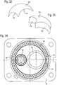
- FIG. 5 illustrated top view of the diffuser 10 of the gas generator shows that the extending from the peripheral wall 16 of the diffuser 10 radially outwardly extending generator flange 18 has a substantially rectangular shape.
- the center axis A of the rotationally symmetrical outer housing with a circular cross section extends through the center M of the generator flange 18th
- the ratio of the length I to the width b of the rectangle, which the generator flange 18 describes, is between 1.12 and 1.31, preferably between 1.16 and 1.27. In the illustrated embodiment, this ratio is about 1.21.
- the ratio of the length I of the rectangle to the outer diameter a of the outer housing (without generator flange 18) is between 1.24 and 1.48, preferably between 1.30 and 1.42. In the illustrated embodiment, this ratio is about 1.36.
- the ratio of the width b of the rectangle to the outer diameter a of the outer housing is between 1.01 and 1.23, preferably between 1.06 and 1.17. In the illustrated embodiment, this ratio is about 1.12.
- FIGS. 6 to 9 For example, various steps of assembling one of the igniter units 26, 28 are shown before it is inserted as a preassembled unit in one of the bottom openings 24 of the closure body 12.
- a sealing ring 86 is first inserted into a lighter socket (see FIG. 7 ) before the lighter 34 or 36 is inserted into the lighter receptacle of the Anzünderitiess 30 and 32 (see FIG. 8 ).
- the protruding circumferential edge 88 of the lighter receptacle is flanged so that the lighter 34 and 36 is held securely in the Anzünderany 30 and 32 (see FIG. 9 ).
- the Anzünderhav 30 and 32 has at a certain point a milled recess 90 as a marker.
- the marker 90 provides an orientation of the igniter unit 26 and 28, respectively.
- An assembly tool used in assembling the inflator is configured to receive the igniter unit 26 or 28 only in a predetermined orientation. When installing the igniter unit 26 or 28, this is installed in the desired orientation with the help of the appropriately equipped tool (see FIGS. 10 to 12 ).
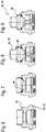
- FIGS. 13 to 26 different embodiments of the lighter sleeve 38 are shown, which is arranged in a predetermined orientation on the first Anzünderarba 30.
- the lighter sleeve 38 a remote from its central axis B or asymmetrically extending from the central axis B marking 92.
- the marker 92 it is possible to use the ensure proper orientation of the lighter sleeve 38 when placed on the first igniter unit 26.
- the marker 92 is formed as a nose extending radially outward from a tapered portion 94 of the side wall 96 of the lighter sleeve 38.
- an assembly tool used in assembly of the gas generator has a recess corresponding to the nose, so that the lighter sleeve 38 can be received only in a predetermined orientation in the assembly tool.
- the assembly tool is set up so that the lighter sleeve 38 during installation then in the in FIG. 27 shown orientation on the first Anzünderentend 30 is plugged.
- FIG. 16 another embodiment of the lighter sleeve 38 is shown.
- the bottom 40 of the lighter sleeve 38 is inclined here relative to a plane perpendicular to the central axis B of the lighter 38 at a certain angle.
- the slope of the igniter sleeve bottom 40 is matched to the axial curvature of the ceiling portion 14 of the diffuser 10, that the igniter sleeve 38 fits only in the predetermined orientation below the ceiling portion 14 of the diffuser 10.
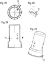
- lighter sleeve 38 with special markings 92 are in the FIGS. 17 and 18, 19 to 22 such as 23 to 26 shown.
- the igniter sleeve 38 Upon activation of the first stage of the gas generator, the igniter sleeve 38 is raised by the pressure generated upon combustion of the booster charge. moved in the direction of the ceiling portion 14 of the diffuser 10. The maximum movement of the igniter sleeve 38 is limited by the ceiling portion 14 of the diffuser 10, which in turn undergoes deformation (bulging). In contrast to the combustion chamber sleeve 60 (as will be explained later), the igniter sleeve 38 does not come off the receiving portion of the first igniter carrier 30, d. H. it arises by lifting, the igniter sleeve 38 no additional outlet opening, which leads out of the igniter chamber 42.
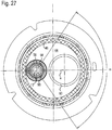
- All variants of the primer sleeve 38 have in common that they have - relative to the center axis B of the primer sleeve 38 - circumferentially unevenly distributed overflow 98. More precisely the overflow openings 98 are limited to a specific area of the side wall 96 of the igniter sleeve 38. When the igniter sleeve 38 is plugged onto the first igniter carrier 30 in the predetermined orientation, the overflow openings 98 are not directed directly at the filter 46.
- the center axes of the outer transfer ports 98 in the specific region of the side wall 96 circumferentially define a limited angular range ⁇ for the discharge of the hot gas (ignition jets) upon burning the booster charge in the lighter chamber 42 (see FIG FIG. 15 ).
- the angle range ⁇ extends on both sides of a connecting line between the center axis B of the lighter sleeve 38 and the maximum distance from the center axis B portion of the filter 46.
- the angle range ⁇ includes those areas of the fuel-filled first combustion chamber 44, in which is not blocked by components of the gas generator distance to the filter 46 maximum.
- the angle range ⁇ is obtuse and is between 90 ° and 135 °, preferably between 100 ° and 120 °. In the illustrated embodiment according to FIG. 27 the angle range ⁇ is about 110 °.
- the angle range ⁇ encloses the combustion chamber sleeve 60.
- the overflow openings 98 are arranged so that the exiting firing jets are not directed directly to the combustion chamber sleeve 60, but primarily to areas where as much fuel as possible is detected on the largest possible length ,
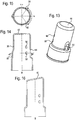
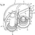
- FIG. 28 the special structure of the second combustion chamber 56 can be seen.
- the bottom 66 of the fuel canister 58 rests on a substantially horizontal surface of the second Anzünder umans 32, and the bent edge portion 70 of the fuel canister bottom 66 is supported on a circumferential outer surface of the second Anzünder umans 32 from.
- the fuel can 58 is thus stable and can be easily filled with fuel.
- the combustion chamber sleeve 60 After filling, the combustion chamber sleeve 60 is pushed onto the fuel can 58 with the second filler 76 in the opposite orientation (in comparison to the fuel can 58). According to the illustrated embodiment, the combustion chamber sleeve 60, which has a slightly greater axial height than the fuel canister 58, pushed so far until the free edge 74 of the open side of the combustion chamber sleeve 60 is held by the lower receiving portion of the second Anzünderliess 32 and the fuel canister opening 64 (here: the open side) is completely covered by the combustion chamber sleeve bottom 72.
- the substantially cylindrical side walls 62, 102 of the fuel canister 58 and the combustion chamber sleeve 60 are then directly opposite each other, more precisely covers the inner surface of the combustion chamber sleeve side wall 102, the outer surface of the fuel canister side wall 62 substantially over the entire axial length of the two sleeves 58, 60th
- a preferably completely circumferential bead 104 is embossed in the side wall 62 of the fuel canister 58.
- the bead 104 serves to stiffen the fuel canister 58, in particular in the upper region near the fuel canister opening 64.
- a plurality of fuel canister bottom holes 106 are formed in the fuel canister bottom 66.
- the side wall 62 of the fuel canister 58 has no openings or holes.
- the pushed onto the fuel can 58, the combustion chamber sleeve 60 is, except for its open side, completely hole-free.
- the second combustion chamber 56 Prior to activation of the second stage of the gas generator, the second combustion chamber 56 is fully closed. In the case of activation of the second stage of the fuel burns in the second combustion chamber 56, and the resulting combustion gas generated in the second combustion chamber 56, an overpressure. Due to the overpressure, the combustion chamber sleeve 60 is pressed in the direction of the ceiling section 14 of the diffuser 10.
- An edge region 108 of the combustion chamber sleeve bottom 72 which is remote from the central axis A of the gas generator either touches the ceiling section 14 of the diffuser 10 already in the non-activated state of the gas generator or after a slight displacement of the combustion chamber sleeve 60.
- the combustion chamber sleeve 60 Since the combustion chamber sleeve 60 is supported on the edge region of the ceiling section 14, the combustion chamber sleeve 60 tilts around the contact point 110 due to the pressure remaining in the second combustion chamber 56, as in FIG. 29 is shown. It is also possible that the combustion chamber sleeve 60 in addition or alternatively deformed non-uniformly for tilting. In any case, a remote from the outer edge of the gas generator portion of the side wall 102 of the combustion chamber sleeve 60 stands out from the second Anzünderanii 32 and releases an exit slit 112, in particular in the detail magnification X of FIG. 29 can be seen.
- the gas produced during combustion of the fuel in the second combustion chamber 56 passes through the holes 106 in the fuel canister bottom 66 to the outlet gap 112 and through this from the second combustion chamber 56 into the first combustion chamber 44.
- this initially has no fuel canister bottom holes 106; the holes are formed only by the pressure generated during the combustion of the fuel and a consequent tearing of the fuel canister bottom 66.
- the distance between the central axis B of the lighter sleeve 38 and the center axis C of the combustion chamber sleeve 60, which in FIG. 30 are shown in the installed state, is between 22.5 and 27.5 mm, preferably between 23.5 and 26.5 mm. In the illustrated embodiment, this distance is about 25 mm.
- the ratio of the minimum inner diameter c of the combustion chamber sleeve 60 to the minimum inner diameter d of the lighter sleeve 38 is between 1.64 and 2.63, preferably between 1.83 and 2.32. In the illustrated embodiment, this ratio is about 2.06.
- the first combustion chamber 44 of the gas generator is, as already mentioned, radially limited at least partially by the circulating filter 46.
- the ratio of the inner diameter f of the filter 46 to the minimum inner diameter d of the lighter sleeve 38 is between 3.19 and 4.76, preferably between 3.50 and 4.27. In the illustrated embodiment, this ratio is about 3.85.
- the ratio of the inner diameter f of the filter 46 to the minimum inner diameter c of the combustion chamber sleeve 60 is between 1.66 and 2.11, preferably between 1.76 and 1.99. In the illustrated embodiment, this ratio is about 1.87.
- the ratio of the outer diameter a of the gas generator, more particularly the outer housing (without consideration of the generator flange 18) to the minimum inner diameter d of the lighter sleeve 38 is between 4.09 and 5.98, preferably between 4.46 and 5.39. In the illustrated embodiment, this ratio is preferably about 4.89.
- the ratio of the outer diameter a of the gas generator to the minimum inner diameter c of the combustion chamber sleeve 60 is between 2.13 and 2.66, preferably between 2.24 and 2.5. In the illustrated embodiment, this ratio is about 2.38.
- the axial height of the contact region between the igniter sleeve 38 and the first igniter carrier 30 is greater than the axial height of the contact region between the combustion chamber sleeve and the second igniter carrier 32nd
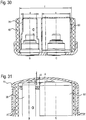
- FIG. 31 the arrangement of the igniter sleeve 38 and the combustion chamber sleeve 60 relative to the ceiling portion 14 of the diffuser 10 is shown. Relative to the center axis A of the diffuser 10, both the axial distance g between the combustion chamber sleeve 60 and the ceiling section 14 and the axial distance i between the igniter sleeve 38 and the ceiling section 38 vary.
- the combustion chamber sleeve 60 contacts the ceiling section 14 of the diffuser 10 already in the non-activated state of the gas generator at the contact point 110 in the outer edge region of the gas generator.
- the axial distance g between the combustion sleeve 60 and the ceiling portion 14 of the diffuser 10 is greatest at the central axis A of the diffuser 10 and decreases continuously with increasing radial distance from the central axis A.
- the maximum distance g is between 2.3 and 3.7 mm, preferably between 2.7 and 3.3 mm. In the illustrated embodiment, this maximum distance g is about 3.0 mm.
- the axial distance i of the igniter sleeve 38 arranged next to the central axis A of the diffuser 10 is also not constant, but steadily decreases with increasing radial distance from the central axis A of the diffuser 10.
- the maximum distance i between the igniter sleeve 38 and the ceiling portion 14 of the diffuser 10 is between 2.1 and 3.5 mm, preferably between 2.5 and 3.1 mm. In the illustrated embodiment, this maximum distance i is about 2.8 mm.
- FIGS. 32 and 33 In each case, a part 114 of the two-part first filling body 82 of the second embodiment variant is shown, which is arranged in the first combustion chamber 44 between the fuel and the ceiling section 14 of the diffuser 10 and both in the high first design (see FIG. 1 ) as well as the flat second design (see FIG. 2 ) can be used.
- the first filling body 82 made of silicone can also be made in one piece.
- the two parts 114 preferably have the in the FIGS. 32 and 33 shown double crescent shape.
- the first packing 82 has two recesses 116, 118 into which the igniter sleeve 38 and the combustion chamber sleeve 60 protrude.
- the smaller first recess 116 is circular and matched to the upper outer diameter of the lighter 38.
- the larger second recess 118 is also circular and tuned to the upper outer diameter of the combustion chamber sleeve 60.
- the ratio of the diameter of the larger second recess 118 to the diameter of the smaller first recess 116 is between 1.52 and 2.25, preferably between 1.67 and 2.03. In the illustrated embodiment, this ratio is about 1.84.
- FIG. 34 is a section through the gas generator according to the first design (see FIG. 1 ), which shows the filter 46 in an upper area of the gas generator.
- the filter 46 which in the FIGS. 35 and 36 is shown separately, has a critical filter section 120 which comes closer to the combustion chamber sleeve 60 than the remaining areas of the filter 46.
- This critical filter section 120 has a reduced thickness compared to the adjacent regions of the filter 46. As a result, a gap 122 is formed between the combustion chamber sleeve 60 and the critical filter section 120.
- the critical filter section 120 is compressed in the radial direction, i. H. the filter material is compressed higher in the critical filter section 120 than in the adjacent areas.
- combustion chamber sleeve 60 has an increased material thickness in the area facing the critical filter section 120 (see also FIGS. 1 and 5 ).
- the upper part of the combustion chamber sleeve 60 is thickened completely circumferentially.
- the ratio of the minimum radial thickness j of the critical filter section 120 to the thickness k of the adjacent regions of the filter 46 is between 0.43 and 0.93, preferably between 0.53 and 0.78. In the illustrated embodiment, this ratio is about 0.65.
- the ratio of the minimum radial thickness j of the critical filter section 120 to the maximum width m of the gap 122 between the combustor sleeve 60 and the critical filter section 120 is between 1.17 and 2.85, preferably between 1.50 and 2.23. In the illustrated embodiment, this ratio is about 1.83.
- the filter 46 extends generally in the axial direction beyond the axially extending peripheral wall 16 of the diffuser 10 in the region of the closure body.
- the raised edge 22 of the closure body 12 has at least one support portion 124 which forms an axial support for the filter 46.
- the support portion 124 may be formed by a fully circumferential embossed bead or by a plurality of circumferentially spaced apart beads.
- the filter 46 is supported only with a radially outer region on the or the support portions 124.
Landscapes
- Physics & Mathematics (AREA)
- Fluid Mechanics (AREA)
- Engineering & Computer Science (AREA)
- Mechanical Engineering (AREA)
- Air Bags (AREA)
Description
Die Erfindung betrifft einen Gasgenerator für eine Schutzeinrichtung in einem Fahrzeug nach dem Oberbegriff des Patentanspruchs 1. Die Erfindung betrifft ferner ein Gassackmodul für ein Fahrzeug.The invention relates to a gas generator for a protective device in a vehicle according to the preamble of
Ein solcher Gasgenerator umfasst einen mit einem Treibstoff gefüllten Treibstoffkanister mit einem Treibstoffkanisterboden und einer dem Treibstoffkanisterboden entgegengesetzten Treibstoffkanisteröffnung, die mittels eines Brennkammerbauteils geschlossen ist, wobei das Brennkammerbauteil eine Brennkammerhülse ist, die eine einer bestimmten Aktivierungsstufe des Gasgenerators zugeordnete Brennkammer wenigstens teilweise umschließt, wobei die Brennkammerhülse eine Brennkammerhülsenöffnung oder eine offene Seite und einen dazu entgegengesetzten Brennkammerhülsenboden aufweist, der die Treibstoffkanisteröffnung abdeckt, wobei am Brennkammerhülsenboden ein zweiter Füllkörper angeordnet ist.Such a gas generator comprises a fuel tank filled with a fuel canister having a fuel canister bottom and a fuel canister bottom opposite fuel canister opening closed by a combustor component, the combustor component being a combustor shell at least partially surrounding a combustion chamber associated with a particular activation stage of the gas combustor a combustion chamber sleeve opening or an open side and an opposite thereto Brennkammerhülsenboden which covers the fuel canister opening, wherein the combustion chamber sleeve bottom, a second packing is arranged.
Ein derartiger Gasgenerator ist beispielsweise in der
Die Anforderungen an die Effektivität eines Gasgenerators sind generell sehr hoch. In kürzester Zeit muss eine bestimmte Menge an Gas bereitgestellt werden, das nicht zu heiß und möglichst partikelfrei sein soll. Ein Gasgenerator sollte auch möglichst leicht sein und wenig Bauraum in Anspruch nehmen, damit z. B. im Falle des Einbaus in einem Lenkrad bestimmte Vorgaben des Lenkraddesigns eingehalten werden können.The requirements for the effectiveness of a gas generator are generally very high. In a short time, a certain amount of gas must be provided, which should not be too hot and as free of particles as possible. A gas generator should also be as light and take up little space, so z. B. in the case of installation in a steering wheel certain specifications of the steering wheel design can be met.
Der Erfindung liegt daher die Aufgabe zugrunde, einen kompakten und effektiven Gasgenerator mit einem sehr effizienten Aufbau, der den obigen Anforderungen genügt, zu schaffen.The invention is therefore based on the object to provide a compact and effective gas generator with a very efficient structure that meets the above requirements.
Für einen Gasgenerator der eingangs genannten Art wird diese Aufgabe erfindungsgemäß durch die kennzeichnenden Merkmale des Patentanspruchs 1 gelöst.For a gas generator of the type mentioned, this object is achieved by the characterizing features of
Erfindungsgemäß ist der Gasgenerator also derart ausgestaltet, dass im Treibstoffkanisterboden eine zentrale Treibstoffkanisterbodenöffnung zur Aufnahme eines Trägerbauteils gebildet ist und der Treibstoffkanister und die Brennkammerhülse zwei offene, im Wesentlichen zylindrische Hülsen sind, die entgegengesetzt orientiert ineinandergesteckt sind, sodass sich eine innere oder äußere Mantelfläche des Treibstoffkanisters und eine äußere bzw. innere Mantelfläche der Brennkammerhülse im Wesentlichen über die gesamte axiale Länge der Mantelflächen überdecken, wobei die Brennkammerhülse außenseitig auf den Treibstoffkanister aufgeschoben ist.According to the invention, the gas generator is thus designed such that a central fuel canister bottom opening for receiving a carrier component is formed in the fuel canister bottom and the fuel canister and the combustor sleeve are two open, substantially cylindrical sleeves, which are inserted into one another in an oppositely oriented manner, so that an inner or outer circumferential surface of the fuel canister and cover an outer or inner circumferential surface of the combustion chamber sleeve substantially over the entire axial length of the lateral surfaces, wherein the combustion chamber sleeve is pushed on the outside of the fuel canister.
Ein Vorzug dieser Gestaltung ist, dass die Brennkammerhülse nicht in Kontakt mit dem Treibstoff kommt, um eine Beschädigung des Treibstoffs und/oder eine Behinderung beim Aufschieben der Brennkammerhülse auszuschließen.An advantage of this design is that the combustion chamber sleeve does not come into contact with the fuel in order to prevent damage to the fuel and / or obstruction when pushing the combustion chamber sleeve.
Zur Verstärkung des Treibstoffkanisters kann dieser in der Nähe der Treibstoffkanisteröffnung eine Sicke oder Rippe aufweisen, die vorzugsweise, bezogen auf eine Mittelachse des Treibstoffkanisters, in Umfangsrichtung vollständig umläuft. Dadurch kann einer unerwünschten Deformierung bei der Handhabung des Treibstoffkanisters entgegengewirkt werden.To reinforce the fuel canister, this may have in the vicinity of the fuel canister opening a bead or rib, which preferably, relative to a central axis of the fuel canister, completely rotates in the circumferential direction. This can be counteracted an undesirable deformation in the handling of the fuel canister.
Zur Anbringung des Treibstoffkanisters im Gasgenerator kann im Treibstoffkanisterboden vorteilhaft eine zentrale Treibstoffkanisterbodenöffnung zur Aufnahme eines Anzünderträgers gebildet sein.For mounting the fuel canister in the gas generator may be formed in the fuel canister bottom advantageously a central fuel canister bottom opening for receiving a Anzünderträgers.
Um eine stabile Halterung des Treibstoffkanisters zu ermöglichen, ist Treibstoffkanisterbodenöffnung durch einen vorzugsweise umgebogenen inneren Randabschnitt des Treibstoffkanisterbodens gebildet, der sich vom Treibstoffkanisterboden in das Innere des Treibstoffkanisters erstreckt. Der Randabschnitt kann sich an einer Haltefläche des Trägerbauteils abstützen.To permit stable retention of the fuel canister, fuel canister bottom opening is formed by a preferably bent inner edge portion of the fuel canister bottom which extends from the fuel canister bottom into the interior of the fuel canister. The edge section can be supported on a holding surface of the carrier component.
Damit das beim Abbrand des Treibstoffs im Treibstoffkanister entstehende Gas aus dem Treibstoffkanister entweichen kann, sind vorzugsweise im Treibstoffkanisterboden mehrere Löcher gebildet.In order for the gas formed during combustion of the fuel in the fuel can to escape from the fuel canister, several holes are preferably formed in the fuel canister bottom.
Dagegen ist die Brennkammerhülse, abgesehen von der Brennkammerhülsenöffnung bzw. der offenen Seite, vorzugsweise lochfrei.In contrast, the combustion chamber sleeve, apart from the combustion chamber sleeve opening or the open side, preferably without holes.
Gemäß einer bevorzugten Art der Befestigung ist die Brennkammerhülse auf einen Anzünderträger aufgesteckt, sodass bei entsprechender Auslegung als Presspassung keine weitere Befestigungsmaßnahme notwendig ist.According to a preferred type of attachment, the combustion chamber sleeve is plugged onto a Anzünderträger, so that with appropriate design as a press fit no further attachment measure is necessary.
Bevorzugte Materialien für den Treibstoffkanister sind Aluminium, Kupfer, Kunststoff oder Stahl; die Brennkammerhülse ist bevorzugt aus Stahl gebildet.Preferred materials for the fuel canister are aluminum, copper, plastic or steel; the combustion chamber sleeve is preferably formed from steel.
Eine definierte Anordnung der Brennkammerhülse relativ zum Treibstoffkanister wird bevorzugt dadurch erreicht, dass zumindest ein Teil einer sich zwischen der Treibstoffkanisteröffnung und dem Treibstoffkanisterboden erstreckenden Seitenwand des Treibstoffkanisters zumindest einem Teil einer sich zwischen der Brennkammerhülsenöffnung bzw. der offenen Seite der Brennkammerhülse und dem Brennkammerhülsenboden erstreckenden Seitenwand der Brennkammerhülse unmittelbar gegenüberliegt.A defined arrangement of the combustion chamber sleeve relative to the fuel canister is preferably achieved in that at least a portion of a side wall of the fuel canister extending between the fuel canister opening and the fuel canister bottom at least a portion of a side wall extending between the Brennkammerhülsenöffnung and the open side of the combustion sleeve and the Brennkammerhülsenboden Combustor sleeve directly opposite.
In einer Ausführungsform der Erfindung kann der Gasgenerator einen Diffusor umfassen, der vorzugsweise mit einem Verschlusskörper ein im Wesentlichen rotationssymmetrisches Außengehäuse des Gasgenerators bildet. Der Diffusor weist mehr als 12, vorzugsweise mehr als 14, weiter vorzugsweise 23 Ausströmöffnungen auf, die in einer Reihe angeordnet sind. Die hohe Zahl von Ausströmöffnungen sorgt für eine gleichmäßige Gasausströmung in den Gassack. Außerdem erlaubt die Anordnung der Ausströmöffnungen in einer Reihe eine einfach zu gestaltende Verdämmung auf der Innenseite des Diffusors, z. B. durch ein schmales Verdämmband.In one embodiment of the invention, the gas generator may comprise a diffuser, which preferably forms a substantially rotationally symmetrical outer housing of the gas generator with a closure body. The diffuser has more than 12, preferably more than 14, more preferably 23 outflow openings, which are arranged in a row. The high number of outflow openings ensures even gas outflow into the gas bag. In addition, the arrangement of the outflow openings in a row allows easy to design damming on the inside of the diffuser, z. B. by a narrow Verdammmband.
Ist die Anzahl der Ausströmöffnungen in der Reihe groß genug gewählt, reicht es aus, dass der Diffusor nur eine einzige Reihe von Ausströmöffnungen aufweist.If the number of outflow openings in the row chosen large enough, it is sufficient that the diffuser has only a single row of outflow openings.
Insbesondere kann es bei einer Ausführungsform der Erfindung sein, dass der Diffusor - bezogen auf eine Mittelachse A des Diffusors - von einem Befestigungsflansch des Gasgenerators ringförmig umgeben ist.In particular, it may be in one embodiment of the invention that the diffuser - with respect to a central axis A of the diffuser - is surrounded annularly by a mounting flange of the gas generator.
Insbesondere kann eine effiziente Ausgestaltung des erfindungsgemäßen Gasgenerators vorsehen, dass das Verhältnis des Außenumfangs des Diffusors in mm zu der Anzahl der Ausströmöffnungen in der Reihe kleiner als 16,5, vorzugsweise kleiner als 14,1, weiter vorzugsweise kleiner als 9,85 ist, weiter vorzugsweise zwischen 7,57 und 9,85, weiter vorzugsweise zwischen 8,20 und 8,96 liegt und weiter vorzugsweise etwa 8,56 beträgt.In particular, an efficient embodiment of the gas generator according to the invention can provide that the ratio of the outer circumference of the diffuser in mm to the number of outflow openings in the row is less than 16.5, preferably less than 14.1, more preferably less than 9.85 preferably between 7.57 and 9.85, more preferably between 8.20 and 8.96 and more preferably about 8.56.
Ein besonders günstiges Gasausströmverhalten ergibt sich dadurch, dass die Ausströmöffnungen wenigstens zwei, vorzugsweise drei unterschiedliche Strömungsquerschnitte haben, wobei die Ausströmöffnungen vorzugsweise kreisförmig sind und die unterschiedlichen Strömungsquerschnitte durch unterschiedliche Durchmesser der kreisförmigen Ausströmöffnungen bestimmt sind.A particularly favorable gas outflow behavior results from the fact that the outflow openings have at least two, preferably three different flow cross sections, wherein the outflow openings are preferably circular and the different flow cross sections are determined by different diameters of the circular outflow openings.
Gemäß einer vorteilhaften Ausgestaltung haben, bezogen auf eine Mittelachse des Diffusors, gegenüberliegende Ausströmöffnungen den gleichen Strömungsquerschnitt. Dies gilt natürlich nur für Ausströmöffnungen, denen tatsächlich eine andere Ausströmöffnung gegenüberliegt.According to an advantageous embodiment, relative to a central axis of the diffuser, opposite outflow openings have the same flow cross-section. Of course, this only applies to outflow openings which are actually opposite to another outflow opening.
Eine weitere vorteilhafte Ausgestaltung sieht vor, dass unmittelbar benachbarte Ausströmöffnungen unterschiedliche Strömungsquerschnitte haben.A further advantageous embodiment provides that immediately adjacent outflow openings have different flow cross sections.
In einer bevorzugten Ausführungsform der Erfindung haben die Ausströmöffnungen wenigstens drei unterschiedliche Strömungsquerschnitte. In der Reihe der Ausströmöffnungen ist zumindest teilweise eine sich wiederholende Abfolge der Art folgenden Art vorgesehen: erster Strömungsquerschnitt, zweiter Strömungsquerschnitt, erster Strömungsquerschnitt, dritter Strömungsquerschnitt. Vorzugsweise ist der erste Strömungsquerschnitt ein kleiner, der zweite Strömungsquerschnitt ein mittlerer und der dritte Strömungsquerschnitt ein großer Strömungsquerschnitt.In a preferred embodiment of the invention, the outflow openings have at least three different flow cross sections. In the row of outflow openings, a repeating sequence of the following type is provided at least partially: first flow cross section, second flow cross section, first flow cross section, third flow cross section. Preferably, the first flow cross section is a smaller, the second flow cross section a middle and the third flow cross section a large flow cross section.
Außerdem sieht die bevorzugte Ausführungsform der Erfindung vor, dass das Verhältnis des Außenumfangs des Diffusors in mm zur Anzahl der Ausströmöffnungen mit dem kleinem Strömungsquerschnitt kleiner als 19,7 ist, vorzugsweise zwischen 15,1 und 19,7 liegt und weiter vorzugsweise etwa 17,9 beträgt.In addition, the preferred embodiment of the invention provides that the ratio of the outer circumference of the diffuser in mm to the number of outflow openings with the small flow cross section is less than 19.7, preferably between 15.1 and 19.7 and more preferably about 17.9 is.
Hinsichtlich der anderen Strömungsquerschnitte sieht die bevorzugte Ausführungsform der Erfindung vor, dass das Verhältnis des Außenumfangs des Diffusors in mm zur Anzahl der Ausströmöffnungen mit dem mittleren Strömungsquerschnitt und/oder zur Anzahl der Ausströmöffnungen mit dem großen Strömungsquerschnitt kleiner als 39,4 ist, vorzugsweise zwischen 28,2 und 39,4 liegt und weiter vorzugsweise etwa 32,8 beträgt.With regard to the other flow cross sections, the preferred embodiment of the invention provides that the ratio of the outer circumference of the Diffuser in mm to the number of outflow openings with the average flow cross-section and / or the number of outflow openings with the large flow cross-section is less than 39.4, preferably between 28.2 and 39.4, and more preferably about 32.8.
Bezüglich der Gasausströmung ist ein Verhältnis des Gesamtströmungsquerschnitts aller Ausströmöffnungen der Reihe in mm2 zum Außenumfang des Diffusors in mm vorteilhaft, das größer als 110 ist, vorzugsweise zwischen 110 und 139 liegt und weiter vorzugsweise etwa 124 beträgt.With respect to the gas outflow, a ratio of the total flow area of all outflow openings of the series in mm 2 to the outer circumference of the diffuser in mm is advantageous, which is greater than 110, preferably between 110 and 139 and more preferably approximately 124.
Die Abstände zwischen benachbarten Ausströmöffnungen in der Reihe sind vorzugsweise gleich groß.The distances between adjacent outflow openings in the row are preferably the same size.
Gemäß einer besonderen Anordnung der Ausströmöffnungen verläuft die Reihe der Ausströmöffnungen bezüglich einer Mittelachse des Diffusors in Umfangsrichtung und hat einen Anfang mit einer ersten Ausströmöffnung sowie ein Ende mit einer letzten Ausströmöffnung. Der Abstand zwischen der ersten und der letzten Ausströmöffnung ist größer, vorzugsweise doppelt so groß wie der Abstand zwischen benachbarten Ausströmöffnungen in der Reihe. Es wird also bewusst eine Ausströmöffnung "ausgelassen".According to a particular arrangement of the outflow openings, the row of outflow openings extends in the circumferential direction with respect to a central axis of the diffuser and has a beginning with a first outflow opening and an end with a last outflow opening. The distance between the first and the last outflow opening is larger, preferably twice as large as the distance between adjacent outflow openings in the row. So it is deliberately an outflow "omitted".
In diesem Fall beträgt der Winkelabstand zwischen benachbarten Ausströmöffnungen 360° / (n + 1), wenn n die Anzahl der Ausströmöffnungen in der Reihe ist.In this case, the angular distance between adjacent exhaust ports is 360 ° / (n + 1) when n is the number of exhaust ports in the series.
Zwischen dem Anfang und dem Ende der Reihe, also in dem Bereich, in dem bewusst keine Ausströmöffnung vorgesehen ist, kann ein Stoß eines Verdämmbandes angeordnet sein.Between the beginning and the end of the row, that is, in the area in which there is intentionally no outflow opening, a shock of Verdämmbandes may be arranged.
Gemäß einer weiteren Ausführungsform kann der Gasgenerator einen, bezogen auf eine Mittelachse des Gasgenerators, radial abstehenden Generatorflansch zur Befestigung des Gasgenerators an einem Generatorträger umfassen. Der Generatorflansch hat im Wesentlichen die Form eines Rechtecks. Die rechteckige Gestaltung des Generatorflanschs ermöglicht eine platzsparende Gestaltung des Generatorträgers und des den Gasgenerator umgebenden Bauraums, insbesondere dann, wenn der Flansch nur geringfügig breiter als der Außendurchmesser des Außengehäuses des Gasgenerators ist. Unter einer im Wesentlichen rechteckigen Form ist dabei nicht unbedingt ein perfektes Rechteck zu verstehen; grundsätzlich rechteckige Formen mit abgerundeten Ecken, randseitigen Ausnehmungen, etc. sollen mit umfasst sein.According to a further embodiment, the gas generator may comprise a generator flange projecting radially with respect to a central axis of the gas generator for fastening the gas generator to a generator carrier. The generator flange has essentially the shape of a rectangle. The rectangular design of the generator flange allows a space-saving design of the generator support and the space surrounding the gas generator space, especially if the flange is only slightly wider than the outer diameter of the outer casing of the gas generator. Under a substantially rectangular shape is not necessarily a perfect rectangle to understand; basically rectangular shapes with rounded corners, edge recesses, etc. should be included.
Bei einem bevorzugten Design ist vorgesehen, dass der Gasgenerator ein Außengehäuse mit einem vorzugsweise kreisförmigen Querschnitt hat, dessen Mittelachse durch den Mittelpunkt des Generatorflanschs verläuft.In a preferred design it is provided that the gas generator has an outer housing with a preferably circular cross-section, whose central axis extends through the center of the generator flange.
Bezüglich der Dimensionen des Generatorflanschs hat sich für die Anbringung des Gasgenerators am Generatorträger ein Verhältnis von Länge zu Breite des Rechtecks zwischen 1,12 und 1,31, vorzugsweise zwischen 1,16 und 1,27 als vorteilhaft herausgestellt. Weiter vorzugsweise beträgt dieses Verhältnis etwa 1,21.With regard to the dimensions of the generator flange, a ratio of length to width of the rectangle between 1.12 and 1.31, preferably between 1.16 and 1.27, has proven advantageous for the attachment of the gas generator to the generator support. More preferably, this ratio is about 1.21.
Ebenfalls bevorzugt wird ein Verhältnis der Länge des Rechtecks zum Außendurchmesser des Außengehäuses, das zwischen 1,24 und 1,48, vorzugsweise zwischen 1,30 und 1,42 liegt und weiter vorzugsweise etwa 1,36 beträgt.Also preferred is a ratio of the length of the rectangle to the outer diameter of the outer housing that is between 1.24 and 1.48, preferably between 1.30 and 1.42, and more preferably about 1.36.
Bezüglich der Breite des Generatorflanschs wird ein Verhältnis der Breite b des Rechtecks zum Außendurchmesser a des Außengehäuses bevorzugt, das zwischen 1,01 und 1,23, vorzugsweise zwischen 1,06 und 1,17 liegt und weiter vorzugsweise etwa 1,12 beträgt.With respect to the width of the generator flange, a ratio of the width b of the rectangle to the outer diameter a of the outer housing is preferred, which is between 1.01 and 1.23, preferably between 1.06 and 1.17 and more preferably about 1.12.
Weitere bevorzugte Ausführungsformen der Erfindung sind Gegenstand der Unteransprüche.Further preferred embodiments of the invention are the subject of the dependent claims.
Im Folgenden wird die Erfindung mit weiteren Einzelheiten anhand der beigefügten Zeichnung näher erläutert. Darin zeigen:
-
Figur 1 -
Figur 2 -
Figur 3 -
Figur 4 eine geschnittene Seitenansicht des Diffusors ausFigur 3 -
Figur 5 eine geschnittene Draufsicht auf einen Diffusor eines erfindungsgemäßen Gasgenerators; -
Figur 6 eine seitliche Schnittansicht eines Anzünderträgers eines erfindungsgemäßen Gasgenerators; -
Figur 7 den Anzünderträger ausFigur 6 mit eingelegtem Dichtring; -
Figur 8 den Anzünderträger ausFigur 7 mit eingesetztem Anzünder; -
Figur 9Figur 9 -
Figur 10 -
Figur 11 denVerschlusskörper aus Figur 10 mit eingesetzten Anzündereinheiten; -
Figur 12Figur 11 ; -
Figur 13 -
Figur 14Figur 13 ; -
Figur 15 eine Schnittansicht entlang der Schnittlinie A-A inFigur 14 -
Figur 16 -
Figur 17 eine seitliche Schnittansicht einer Anzünderhülse nach einer dritten Ausführungsvariante; -
Figur 18Figur 17 ; -
Figur 19 eine perspektivische Ansicht einer Anzünderhülse nach einer vierten Ausführungsvariante; -
Figur 20Figur 19 ; -
Figur 21 eine Schnittansicht entlang der Schnittlinie A-A inFigur 20 -
Figur 22Figur 20 -
Figur 23 eine perspektivische Ansicht einer Anzünderhülse nach einer fünften Ausführungsvariante; -
Figur 24Figur 23 ; -
Figur 25 eine Schnittansicht entlang der Schnittlinie A-A inFigur 24 -
Figur 26Figur 25 ; -
Figur 27 eine in einem unteren Bereich des Gasgenerators teilweise geschnittene Draufsicht auf einen erfindungsgemäßen Gasgenerator; -
Figur 28 -
Figur 29 eine seitliche Schnittansicht eines erfindungsgemäßen Gasgenerators nach der zweiten Bauform nach Aktivierung der zweiten Aktivierungsstufe; -
Figur 30 -
Figur 31 einen Ausschnitt einer seitlichen Schnittansicht eines erfindungsgemäßen Gasgenerators; -
Figur 32 -
Figur 33 eine perspektivische Ansicht des Füllkörperteils ausFigur 32 ; -
Figur 34 -
Figur 35 eine Draufsicht auf einen Filter eines erfindungsgemäßen Gasgenerators; -
Figur 36Figur 35 ; und -
Figur 37 eine schematische seitliche Schnittansicht eines erfindungsgemäßen Gasgenerators nach der ersten Bauform in einer Ausführungsvariante.
-
FIG. 1 a sectional side view of a gas generator according to the invention according to a first design; -
FIG. 2 a sectional side view of a gas generator according to the invention according to a second design; -
FIG. 3 a sectional plan view of a diffuser of a gas generator according to the invention; -
FIG. 4 a sectional side view of the diffuserFIG. 3 ; -
FIG. 5 a sectional plan view of a diffuser of a gas generator according to the invention; -
FIG. 6 a side sectional view of a Anzünderträgers a gas generator according to the invention; -
FIG. 7 the igniter carrierFIG. 6 with inserted sealing ring; -
FIG. 8 the igniter carrierFIG. 7 with inserted lighter; -
FIG. 9 the igniter carrier and the lighterFIG. 9 in pre-assembled condition; -
FIG. 10 a side sectional view of a closure body of a gas generator according to the invention; -
FIG. 11 the closure bodyFIG. 10 with inserted igniter units; -
FIG. 12 a partial plan view of the closure body and the igniter unitsFIG. 11 ; -
FIG. 13 a perspective view of an igniter sleeve of a gas generator according to the invention according to a first embodiment; -
FIG. 14 a side sectional view of the lighter sleeveFIG. 13 ; -
FIG. 15 a sectional view taken along the section line AA inFIG. 14 ; -
FIG. 16 a side sectional view of an igniter sleeve according to a second embodiment; -
FIG. 17 a side sectional view of an igniter sleeve according to a third embodiment; -
FIG. 18 a sectional view taken along the section line AA inFIG. 17 ; -
FIG. 19 a perspective view of an igniter sleeve according to a fourth embodiment; -
FIG. 20 a side sectional view of the lighter sleeveFIG. 19 ; -
FIG. 21 a sectional view taken along the section line AA inFIG. 20 ; -
FIG. 22 a sectional view taken along the section line CC inFIG. 20 ; -
FIG. 23 a perspective view of an igniter sleeve according to a fifth embodiment; -
FIG. 24 a side sectional view of the lighter sleeveFIG. 23 ; -
FIG. 25 a sectional view taken along the section line AA inFIG. 24 ; -
FIG. 26 a sectional view taken along the section line CC inFIG. 25 ; -
FIG. 27 a partially cut in a lower portion of the gas generator top view of a gas generator according to the invention; -
FIG. 28 a partially sectioned perspective view of a gas generator according to the invention without a diffuser; -
FIG. 29 a sectional side view of a gas generator according to the invention according to the second design after activation of the second activation stage; -
FIG. 30 a side sectional view of a gas generator according to the invention without diffuser and filler; -
FIG. 31 a section of a side sectional view of a gas generator according to the invention; -
FIG. 32 a plan view of a Füllkörperteil for the first combustion chamber of a gas generator according to the invention according to a variant embodiment; -
FIG. 33 a perspective view of the FüllkörperteilsFIG. 32 ; -
FIG. 34 a cut in an upper portion of the gas generator top view of a gas generator according to the invention; -
FIG. 35 a plan view of a filter of a gas generator according to the invention; -
FIG. 36 a sectional view of the filter along the line AA inFIG. 35 ; and -
FIG. 37 a schematic sectional side view of a gas generator according to the invention according to the first design in a variant.
In der nachfolgenden detaillierten Beschreibung bevorzugten Ausführungsformen und -varianten der Erfindung werden zur Erleichterung des Verständnisses Angaben wie oben, unten, etc. verwendet. Diese Angaben beziehen sich auf eine Orientierung des Gasgenerators, wie er in den
In
Der Diffusor 10 hat einen gewölbten Deckenabschnitt 14 und eine daran anschließende, im Wesentlichen zylindrische Umfangswand 16. Von der dem Deckenabschnitt 14 abgewandten Seite der Umfangswand 16 erstreckt sich ein Generatorflansch 18 radial nach außen. Der Generatorflansch 18 soll im Folgenden nicht als Bestandteil des Außengehäuses angesehen werden.The
Der Verschlusskörper 12 hat einen im Wesentlichen ebenen Boden 20 und einen außen umlaufenden, hochgezogenen Rand 22, der an der Innenseite der Umfangswand 16 des Diffusors 10 anliegt. Die Wanddicke des Verschlusskörpers 12 ist wenigstens abschnittsweise größer als die des Diffusors 10. Insbesondere der Boden 20 des Verschlusskörpers 12 ist dicker als die Umfangswand 16 und der Deckenabschnitt 14 des Diffusors 10.The
Das aus dem Diffusor 10 (ohne Generatorflansch 18) und dem Verschlusskörper 12 gebildete Außengehäuse ist bezüglich der Mittelachse A des Gasgenerators im Wesentlichen rotationssymmetrisch, wie es für sogenannte "disk-shape"-Gasgeneratoren, zu denen auch der Gegenstand der Erfindung zählt, üblich ist. Die Mittelachse A des Gasgenerators fällt somit mit der Mittelachse des Diffusors 10 und des Verschlussköpers 12 zusammen.The outer housing formed from the diffuser 10 (without generator flange 18) and the
Der Verschlusskörper 12 hat zwei von der Mittelachse A des Gasgenerators unterschiedlich weit beabstandete Bodenöffnungen 24, die zur Aufnahme vormontierter Anzündereinheiten 26, 28 dienen. Beide Anzündereinheiten 26,28 umfassen einen Anzünderträger 30 bzw. 32 und einen in diesen eingesetzten Anzünder 34 bzw. 36.The
Die erste (in
Die Anzünderhülse 38 ist vollständig von einer ersten Brennkammer 44 umgeben, die mit einem Treibstoff (nicht gezeigt), insbesondere in Tablettenform, gefüllt ist. Wie in
Die erste Brennkammer 44 ist axial durch den Deckenabschnitt 14 des Diffusors 10 und den Boden 20 des Verschlusskörpers 12 begrenzt. Radial ist die erste Brennkammer 44 durch einen vollständig umlaufenden, ringförmigen Filter 46 begrenzt, der entlang der Innenseite des hochgezogenen Rands 22 des Verschlusskörpers 12 bzw. entlang der Innenseite der Umfangswand 16 des Diffusors 10 verläuft, wobei zwischen dem Filter 46 und der Umfangswand 16 ein Ringspalt 48 gebildet ist.The
Unterhalb des Filters 46 ist die erste Brennkammer 44 in radialer Richtung durch ein Stützelement 50 begrenzt, auf dem sich der Filter 46 axial abstützt. Im Falle eines nicht vollständig umlaufend ausgebildeten Stützelements 50 ist die erste Brennkammer 44 in den dazwischenliegenden Bereichen durch den Rand 22 des Verschlusskörpers 12 begrenzt. Dadurch, dass sich der Filter 46 nicht bis zum Boden 20 des Verschlusskörpers 12 erstreckt, können Kosten für zusätzliches Filtermaterial und Gewicht eingespart werden.Below the
Zwischen dem Treibstoff der ersten Brennkammer 44 und dem Deckenabschnitt 14 des Diffusors 10 ist ein erster Füllkörper 52 angeordnet. Gemäß der in
Der zweite (in
Der Treibstoffkanister 58 hat eine im Wesentlichen zylindrische Seitenwand 62. Auf einer dem Deckenabschnitt 14 des Diffusors 10 zugewandten axialen Stirnseite weist der Treibstoffkanister 58 eine Treibstoffkanisteröffnung 64 auf; im dargestellten Ausführungsbeispiel ist diese Stirnseite vollständig offen. Auf der entgegengesetzten Stirnseite weist der Treibstoffkanister 58 einen Treibstoffkanisterboden 66 mit einer zentralen Treibstoffkanisterbodenöffnung 68 auf. Die Treibstoffkanisterbodenöffnung 68 ist durch einen umgebogenen inneren Randabschnitt 70 gebildet, der sich vom Treibstoffkanisterboden 66 in das Innere des Treibstoffkanisters 58 erstreckt. Der Treibstoffkanisterboden 66 mit dem umgebogenen inneren Randabschnitt 70 stützt sich an einem oberen Aufnahmeabschnitt des zweiten Anzünderträgers 32 ab. Zwischen Treibstoffkanister 58 und zweitem Anzünderträger 32 besteht eine Presspassung, sodass keine weitere Befestigungsmaßnahme (Schweißen, etc.) notwendig ist.The
Auf den Treibstoffkanister 58 ist die Brennkammerhülse 60 in umgekehrter Orientierung so aufgeschoben, dass ein Brennkammerhülsenboden 72, der dem Deckenabschnitt 14 des Diffusors 10 gegenüberliegt, die offene Seite des Treibstoffkanisters 58 vollständig verschließt. Der freie Rand 74 auf der offenen Seite der Brennkammerhülse 60 ist auf einen unteren Aufnahmeabschnitt des zweiten Anzünderträgers 32 aufgesteckt. Zwischen Brennkammerhülse 60 und zweitem Anzünderträger 32 besteht eine Presspassung, sodass keine weitere Befestigungsmaßnahme (Schweißen, etc.) notwendig ist.On the
Am Brennkammerhülsenboden 72 ist ein fest mit diesem verbundener zweiter Füllkörper 76 angeordnet, der in den Treibstoffkanister 58 hineinragt. Ansonsten ist die zweite Brennkammer 56 mit Treibstoff (nicht gezeigt), insbesondere in Tablettenform, gefüllt.At Brennkammerhülsenboden 72 a fixedly connected to this
Nachfolgend wird die grundlegende Funktionsweise des Gasgenerators beschrieben. Besonderheiten der Funktionsweise werden später detailliert erläutert.The basic operation of the gas generator is described below. Special features of the functionality will be explained in detail later.
Wie bereits erwähnt, ist der Gasgenerator zweistufig konzipiert. Bei Aktivierung der ersten Stufe zündet der erste Anzünder 34 die Verstärkerladung in der Anzünderkammer 42. Während des Abbrands der Verstärkerladung treten "Anzündstrahlen" (Heißgas) aus Überströmöffnungen der Anzünderhülse 38 (in
Bei einer Aktivierung der zweiten Stufe, die in Abhängigkeit von der erkannten Unfallsituation und der Aktivierungssteuerung grundsätzlich nach, vor oder unabhängig von der ersten Stufe erfolgen kann, zündet der zweite Anzünder 36 den Treibstoff in der zweiten Brennkammer 56. Das beim Abbrand des Treibstoffs entstehende Gas kann durch einen besonderen Mechanismus, der später noch genauer erläutert wird, aus der zweiten Brennkammer 56 in die erste Brennkammer 44 entweichen. Von dort gelangt das Gas durch den Filter 46 und die Ausströmöffnungen 78 in den Gassack.In an activation of the second stage, which in principle can be done depending on the detected accident situation and the activation control, before or independently of the first stage, ignites the
Der in
Die Bauhöhe des Gasgenerators, insbesondere die axiale Höhe h1 des Außengehäuses, liegt bei der ersten Bauform zwischen 50 und 70 mm und beträgt beim dargestellten Ausführungsbeispiel gemäß
Bei der ersten Bauform des Gasgenerators liegt das Verhältnis des Volumens der ersten Brennkammer 44 zum Volumen der zweiten Brennkammer 56 zwischen 2,34 und 3,27, vorzugsweise zwischen 2,54 und 3,00. Beim dargestellten Ausführungsbeispiel gemäß
Bei der ersten Bauform des Gasgenerators liegt das Verhältnis des Volumens der ersten Brennkammer 44 zum Volumen der Anzünderhülse 38 zwischen 13,5 und 31,0, vorzugsweise zwischen 16,0 und 24,0. Beim dargestellten Ausführungsbeispiel gemäß
Bei der ersten Bauform des Gasgenerators liegt das Verhältnis des Außendurchmessers a des Außengehäuses des Gasgenerators (ohne Generatorflansch 18, siehe
In
Im Vergleich zur ersten Bauform sind bei der zweiten Bauform die axialen Ausdehnungen des Verschlusskörpers 12, der Anzünderhülse 38, des Treibstoffkanisters 58, der Brennkammerhülse 66, der Anzünderkammer 42 sowie der beiden Brennkammern 44, 56 reduziert.Compared to the first design, the axial dimensions of the
Bei der zweiten Bauform erstreckt sich der Filter 46 vom Deckenabschnitt 14 des Diffusors 10 bis zum Bodenbereich des Verschlusskörpers 12. An seinem unteren Ende stützt sich der Filter 46 axial an einem schrägen Übergangsbereich 80 des Verschlusskörpers 12 ab, weshalb ein separates Stützelement für den Filter 46 wie bei der ersten Bauform hier nicht vorgesehen ist.In the second design, the
Anstelle des ersten Füllkörpers 52 aus Streckmetall mit den elastischen fingerförmigen Abschnitten 54 ist gemäß einer zweiten Ausführungsvariante ein flacher erster Füllkörper 82 aus nachgiebigem Silikon vorgesehen. Die in
Der in
Die Bauhöhe des Gasgenerators, insbesondere die axiale Höhe h2 des Außengehäuses, liegt bei der zweiten Bauform zwischen 30 und 50 mm und beträgt beim dargestellten Ausführungsbeispiel gemäß
Bei der zweiten Bauform des Gasgenerators liegt das Verhältnis des Volumens der ersten Brennkammer 44 zum Volumen der zweiten Brennkammer 56 zwischen 2,07 und 3,78, vorzugsweise zwischen 2,41 und 3,21. Beim dargestellten Ausführungsbeispiel gemäß
Bei der zweiten Bauform des Gasgenerators liegt das Verhältnis des Volumens der ersten Brennkammer 44 zum Volumen der Anzünderhülse 38 zwischen 9,00 und 35,0, vorzugsweise zwischen 11,6 und 22,0. Beim dargestellten Ausführungsbeispiel gemäß
Bei der zweiten Bauform des Gasgenerators liegt das Verhältnis des Außendurchmessers a des Außengehäuses des Gasgenerators zur Höhe h2 des Außengehäuses zwischen 1,38 und 1,78 und beträgt beim dargestellten Ausführungsbeispiel gemäß
Nachfolgend werden verschiedene Besonderheiten des in den
Die
In der Reihe sind mehr als zwölf, vorzugsweise mehr als vierzehn Ausströmöffnungen 78 vorgesehen. Beim dargestellten Ausführungsbeispiel ist es eine ungerade Anzahl: genau dreiundzwanzig Ausströmöffnungen 78 sind in der Reihe angeordnet. Allgemein ist das Verhältnis des Außenumfangs des Diffusors 10 in Millimetern zu der Anzahl n der Ausströmöffnungen in der Reihe kleiner als 16,5, vorzugsweise kleiner als 14,1, weiter vorzugsweise kleiner als 9,85. Das Verhältnis liegt weiter vorzugsweise zwischen 7,57 und 9,85, weiter vorzugsweise zwischen 8,20 und 8,96. Beim dargestellten Ausführungsbeispiel beträgt dieses Verhältnis etwa 8,56.In the series more than twelve, preferably more than fourteen
Wie in
Die Reihe der Ausströmöffnungen 78 läuft nicht vollständig um. Im Uhrzeigersinn betrachtet markiert die mit 78a bezeichnete Ausströmöffnung den Anfang und die mit 78b bezeichnete Ausströmöffnung das Ende der Reihe. Innerhalb der Reihe sind die Abstände zwischen benachbarten Ausströmöffnungen 78 (bezogen auf deren Mittelpunkte) gleich. Der Abstand zwischen der ersten Ausströmöffnung 78a und der letzten Ausströmöffnung 78b ist dagegen doppelt so groß. Da die Anzahl n der Ausströmöffnungen 78 in der Reihe ungerade ist, entsteht somit eine Anordnung der Ausströmöffnungen 78, bei der - bezogen auf die Mittelachse A - jeder Ausströmöffnung 78 eine andere Ausströmöffnung gegenüberliegt, mit einer Ausnahme: Der mit 78c bezeichneten Ausströmöffnung liegt der Bereich zwischen der ersten Ausströmöffnung 78a und der letzten Ausströmöffnung 78b und damit keine Ausströmöffnung gegenüber. In diesem Bereich der Diffusorinnenseite ist ein Stoß des Verdämmbandes 84 angeordnet. Eine Ausströmöffnung würde hier die Dichtheit zum Außenbereich des Gasgenerators hin beeinträchtigen.The row of
Allgemein beträgt der Winkelabstand zwischen benachbarten Ausströmöffnungen 78 bei einer solchen Konstellation (unabhängig davon, ob die Anzahl n der Ausströmöffnungen gerade oder ungerade ist) 360° / (n + 1).Generally, in such a constellation (regardless of whether the number n of outflow openings is even or odd), the angular separation between
Die vorzugsweise kreisförmigen Ausströmöffnungen 78 haben wenigstens zwei unterschiedliche Strömungsquerschnitte; beim dargestellten Ausführungsbeispiel sind es insgesamt drei unterschiedliche Strömungsquerschnitte. Die Ausströmöffnungen 78 sind deshalb in
Die Strömungsquerschnitte (1), (2) und (3) der Ausströmöffnungen 78 sind so gewählt, dass gegenüberliegende Ausströmöffnungen 78 den gleichen Strömungsquerschnitt haben. Dagegen weisen benachbarte Ausströmöffnungen 78 innerhalb der Reihe unterschiedliche Strömungsquerschnitte auf. Beim dargestellten Ausführungsbeispiel wiederholt sich in der Reihe folgende Abfolge der Strömungsquerschnitte: kleiner Strömungsquerschnitt (1) → mittlerer Strömungsquerschnitt (2) → kleiner Strömungsquerschnitt (1) → großer Strömungsquerschnitt (3).The flow cross sections (1), (2) and (3) of the
Das Verhältnis des Außenumfangs des Diffusors 10 (ohne Generatorflansch 18) in mm zur Anzahl der Ausströmöffnungen 78 mit kleinem Strömungsquerschnitt (1) ist kleiner als 19,7 und liegt vorzugsweise zwischen 15,1 und 19,7. Beim dargestellten Ausführungsbeispiel beträgt dieses Verhältnis etwa 17,9.The ratio of the outer circumference of the diffuser 10 (without generator flange 18) in mm to the number of
Das Verhältnis des Außenumfangs des Diffusors 10 in mm zur Anzahl der Ausströmöffnungen 78 mit mittlerem Strömungsquerschnitt (2) sowie zur Anzahl der Ausströmöffnungen 78 mit großem Strömungsquerschnitt (3) ist kleiner als 39,4 und liegt vorzugsweise zwischen 28,2 und 39,4. Beim dargestellten Ausführungsbeispiel beträgt dieses Verhältnis etwa 32,8.The ratio of the outer circumference of the
Das Verhältnis des Gesamtströmungsquerschnitts aller Ausströmöffnungen 78 in der Reihe in mm2 zum Außenumfang des Diffusors 10 in mm ist größer als 110 und liegt vorzugsweise zwischen 110 und 139. Beim dargestellten Ausführungsbeispiel beträgt dieses Verhältnis etwa 124.The ratio of the total flow cross-section of all
Aus der in
Das Verhältnis der Länge I zur Breite b des Rechtecks, welches der Generatorflansch 18 beschreibt, liegt zwischen 1,12 und 1,31, vorzugsweise zwischen 1,16 und 1,27. Beim dargestellten Ausführungsbeispiel beträgt dieses Verhältnis etwa 1,21.The ratio of the length I to the width b of the rectangle, which the
Das Verhältnis der Länge I des Rechtecks zum Außendurchmesser a des Außengehäuses (ohne Generatorflansch 18) liegt zwischen 1,24 und 1,48, vorzugsweise zwischen 1,30 und 1,42. Beim dargestellten Ausführungsbeispiel beträgt dieses Verhältnis etwa 1,36.The ratio of the length I of the rectangle to the outer diameter a of the outer housing (without generator flange 18) is between 1.24 and 1.48, preferably between 1.30 and 1.42. In the illustrated embodiment, this ratio is about 1.36.
Das Verhältnis der Breite b des Rechtecks zum Außendurchmesser a des Außengehäuses liegt zwischen 1,01 und 1,23, vorzugsweise zwischen 1,06 und 1,17. Beim dargestellten Ausführungsbeispiel beträgt dieses Verhältnis etwa 1,12.The ratio of the width b of the rectangle to the outer diameter a of the outer housing is between 1.01 and 1.23, preferably between 1.06 and 1.17. In the illustrated embodiment, this ratio is about 1.12.
In den
Der Anzünderträger 30 bzw. 32 weist an einer bestimmten Stelle eine Einfräsung als Markierung 90 auf. Die Markierung 90 gibt eine Orientierung der Anzündereinheit 26 bzw. 28 vor. Ein beim Zusammenbau des Gasgenerators verwendetes Montagewerkzeug ist so ausgebildet, dass es die Anzündereinheit 26 bzw. 28 nur in einer vorbestimmten Orientierung aufnehmen kann. Beim Einbau der Anzündereinheit 26 bzw. 28 wird diese mithilfe des entsprechend eingerichteten Werkzeugs in der gewünschten Orientierung eingebaut (siehe
In den
Bei der in den
In
Weitere alternative Ausführungsvarianten der Anzünderhülse 38 mit besonderen Markierungen 92 sind in den
Bei Aktivierung der ersten Stufe des Gasgenerators wird die Anzünderhülse 38 durch den beim Abbrand der Verstärkerladung entstehenden Druck nach oben, d.h. in Richtung des Deckenabschnitts 14 des Diffusors 10 bewegt. Die maximale Bewegung der Anzünderhülse 38 ist durch den Deckenabschnitt 14 des Diffusors 10 begrenzt, der seinerseits eine Verformung erfährt (Ausbauchen). Im Gegensatz zur Brennkammerhülse 60 (wie später noch erläutert wird) löst sich die Anzünderhülse 38 nicht vom Aufnahmeabschnitt des ersten Anzünderträgers 30, d. h. es entsteht durch das Anheben, der Anzünderhülse 38 keine zusätzliche Austrittsöffnung, die aus der Anzünderkammer 42 herausführt.Upon activation of the first stage of the gas generator, the
Allen Ausführungsvarianten der Anzünderhülse 38 ist gemeinsam, dass sie - bezogen auf die Mittelachse B der Anzünderhülse 38 - in Umfangsrichtung ungleichmäßig verteilte Überströmöffnungen 98 aufweisen. Genauer gesagt sind die Überströmöffnungen 98 auf einen bestimmten Bereich der Seitenwand 96 der Anzünderhülse 38 beschränkt. Wenn die Anzünderhülse 38 in der vorbestimmten Orientierung auf den ersten Anzünderträger 30 aufgesteckt ist, sind die Überströmöffnungen 98 nicht direkt auf den Filter 46 gerichtet. Die Mittelachsen der äußeren Überströmöffnungen 98 in dem bestimmten Bereich der Seitenwand 96 definieren nämlich in Umfangsrichtung einen begrenzten Winkelbereich α für den Austritt des Heißgases (Anzündstrahlen) beim Abbrennen der Verstärkerladung in der Anzünderkammer 42 (siehe
Wie in
Wie ebenfalls aus
Aus
Nach dem Befüllen wird die Brennkammerhülse 60 mit dem zweiten Füllkörper 76 in entgegengesetzter Orientierung (im Vergleich zum Treibstoffkanister 58) auf den Treibstoffkanister 58 aufgeschoben. Gemäß dem dargestellten Ausführungsbeispiel wird die Brennkammerhülse 60, die eine geringfügig größere axiale Höhe als der Treibstoffkanister 58 aufweist, so weit aufgeschoben, bis der freie Rand 74 der offenen Seite der Brennkammerhülse 60 vom unteren Aufnahmeabschnitt des zweiten Anzünderträgers 32 gehalten wird und die Treibstoffkanisteröffnung 64 (hier: die offene Seite) vollständig durch den Brennkammerhülsenboden 72 abgedeckt ist. Die im Wesentlichen zylindrischen Seitenwände 62, 102 des Treibstoffkanisters 58 und der Brennkammerhülse 60 liegen einander dann unmittelbar gegenüber, genauer gesagt überdeckt die innere Mantelfläche der Brennkammerhülsenseitenwand 102 die äußere Mantelfläche der Treibstoffkanisterseitenwand 62 im Wesentlichen über die gesamte axiale Länge der beiden Hülsen 58, 60.After filling, the
In der Nähe der Treibstoffkanisteröffnung 64, etwa auf Höhe des in den Treibstoffkanister 58 ragenden zweiten Füllkörpers 76, ist in der Seitenwand 62 des Treibstoffkanisters 58 eine vorzugsweise vollständig umlaufende Sicke 104 eingeprägt. Die Sicke 104 dient zur Versteifung des Treibstoffkanisters 58, insbesondere im oberen Bereich nahe der Treibstoffkanisteröffnung 64.In the vicinity of the
Im Treibstoffkanisterboden 66 sind mehrere Treibstoffkanisterbodenlöcher 106 gebildet. Die Seitenwand 62 des Treibstoffkanisters 58 hingegen weist keine Öffnungen oder Löcher auf. Die auf den Treibstoffkanister 58 aufgeschobene Brennkammerhülse 60 ist, abgesehen von ihrer offenen Seite, vollständig lochfrei.In the
Vor der Aktivierung der zweiten Stufe des Gasgenerators ist die zweite Brennkammer 56 vollständig geschlossen. Im Falle einer Aktivierung der zweiten Stufe brennt der Treibstoff in der zweiten Brennkammer 56 ab, und das dabei entstehende Abbrandgas erzeugt in der zweiten Brennkammer 56 einen Überdruck. Durch den Überdruck wird die Brennkammerhülse 60 in Richtung des Deckenabschnitts 14 des Diffusors 10 gedrückt.Prior to activation of the second stage of the gas generator, the
Ein von der Mittelachse A des Gasgenerators entfernter Randbereich 108 des Brennkammerhülsenbodens 72 berührt entweder bereits im nicht aktivierten Zustand des Gasgenerators oder nach einer geringfügigen Verschiebung der Brennkammerhülse 60 nach oben den Deckenabschnitt 14 des Diffusors 10. In jedem Fall begrenzt der Deckenabschnitt 14, der infolge der Gasentwicklung selbst ausbaucht, die axiale Bewegung der Brennkammerhülse 60.An
Da sich die Brennkammerhülse 60 am Randbereich des Deckenabschnitts 14 abstützt, kippt die Brennkammerhülse 60 aufgrund des weiterhin vorhandenen Drucks in der zweiten Brennkammer 56 um die Kontaktstelle 110, wie in
Das beim Abbrand des Treibstoffs in der zweiten Brennkammer 56 entstehende Gas gelangt durch die Löcher 106 im Treibstoffkanisterboden 66 zum Austrittspalt 112 und durch diesen aus der zweiten Brennkammer 56 in die erste Brennkammer 44 hinein. Gemäß einer anderen Ausführungsvariante des Treibstoffkanisters 58 weist dieser anfangs keine Treibstoffkanisterbodenlöcher 106 auf; die Löcher werden erst durch den beim Abbrand des Treibstoffs entstehenden Druck und ein dadurch bedingtes Aufreißen des Treibstoffkanisterbodens 66 gebildet.The gas produced during combustion of the fuel in the
Der Abstand zwischen der Mittelachse B der Anzünderhülse 38 und der Mittelachse C der Brennkammerhülse 60, die in
Das Verhältnis des minimalen Innendurchmessers c der Brennkammerhülse 60 zum minimalen Innendurchmesser d der Anzünderhülse 38 liegt zwischen 1,64 und 2,63, vorzugsweise zwischen 1,83 und 2,32. Beim dargestellten Ausführungsbeispiel beträgt dieses Verhältnis etwa 2,06.The ratio of the minimum inner diameter c of the
Die erste Brennkammer 44 des Gasgenerators ist, wie bereits erwähnt, radial zumindest teilweise durch den umlaufenden Filter 46 begrenzt. Das Verhältnis des Innendurchmessers f des Filters 46 zum minimalen Innendurchmesser d der Anzünderhülse 38 liegt zwischen 3,19 und 4,76, vorzugsweise zwischen 3,50 und 4,27. Beim dargestellten Ausführungsbeispiel beträgt dieses Verhältnis etwa 3,85.The
Das Verhältnis des Innendurchmessers f des Filters 46 zum minimalen Innendurchmesser c der Brennkammerhülse 60 liegt zwischen 1,66 und 2,11, vorzugsweise zwischen 1,76 und 1,99. Beim dargestellten Ausführungsbeispiel beträgt dieses Verhältnis etwa 1,87.The ratio of the inner diameter f of the
Das Verhältnis des Außendurchmessers a des Gasgenerators, genauer gesagt des Außengehäuses (ohne Berücksichtigung des Generatorflanschs 18), zum minimalen Innendurchmesser d der Anzünderhülse 38 liegt zwischen 4,09 und 5,98, vorzugsweise zwischen 4,46 und 5,39. Beim dargestellten Ausführungsbeispiel beträgt dieses Verhältnis vorzugsweise etwa 4,89.The ratio of the outer diameter a of the gas generator, more particularly the outer housing (without consideration of the generator flange 18) to the minimum inner diameter d of the
Das Verhältnis des Außendurchmessers a des Gasgenerators zum minimalen Innendurchmesser c der Brennkammerhülse 60 liegt zwischen 2,13 und 2,66, vorzugsweise zwischen 2,24 und 2,5. Beim dargestellten Ausführungsbeispiel beträgt dieses Verhältnis etwa 2,38.The ratio of the outer diameter a of the gas generator to the minimum inner diameter c of the
Wie ebenfalls aus
In
Der axiale Abstand g zwischen der Brennkammerhülse 60 und dem Deckenabschnitt 14 des Diffusors 10 ist an der Mittelachse A des Diffusors 10 am größten und verringert sich mit zunehmendem radialem Abstand von der Mittelachse A stetig. Der maximale Abstand g liegt zwischen 2,3 und 3,7 mm, vorzugsweise zwischen 2,7 und 3,3 mm. Beim dargestellten Ausführungsbeispiel beträgt dieser maximale Abstand g etwa 3,0 mm.The axial distance g between the
Auch der axiale Abstand i der neben der Mittelachse A des Diffusors 10 angeordneten Anzünderhülse 38 ist nicht konstant, sondern verringert sich mit zunehmendem radialem Abstand von der Mittelachse A des Diffusors 10 stetig. Der maximale Abstand i zwischen der Anzünderhülse 38 und dem Deckenabschnitt 14 des Diffusors 10 liegt zwischen 2,1 und 3,5 mm, vorzugsweise zwischen 2,5 und 3,1 mm. Beim dargestellten Ausführungsbeispiel beträgt dieser maximale Abstand i etwa 2,8 mm.The axial distance i of the
In den
Im eingesetzten Zustand weist der erste Füllkörper 82 zwei Aussparungen 116, 118 auf, in die die Anzünderhülse 38 und die Brennkammerhülse 60 hineinragen. Die kleinere erste Aussparung 116 ist kreisförmig und auf den oberen Außendurchmesser der Anzünderhülse 38 abgestimmt. Die größere zweite Aussparung 118 ist ebenfalls kreisförmig und auf den oberen Außendurchmesser der Brennkammerhülse 60 abgestimmt.In the inserted state, the
Das Verhältnis des Durchmessers der größeren zweiten Aussparung 118 zum Durchmesser der kleineren ersten Aussparung 116 liegt zwischen 1,52 und 2,25, vorzugsweise zwischen 1,67 und 2,03. Beim dargestellten Ausführungsbeispiel beträgt dieses Verhältnis etwa 1,84.The ratio of the diameter of the larger
Dieser kritische Filterabschnitt 120 weist im Vergleich zu den angrenzenden Bereichen des Filters 46 eine verringerte Dicke auf. Dadurch ist zwischen der Brennkammerhülse 60 und dem kritischen Filterabschnitt 120 ein Spalt 122 gebildet. Der kritische Filterabschnitt 120 ist in radialer Richtung komprimiert, d. h. das Filtermaterial ist im kritischen Filterabschnitt 120 höher verdichtet als in den angrenzenden Bereichen.This
Die Brennkammerhülse 60 weist dagegen in dem Bereich, der dem kritischen Filterabschnitt 120 gegenüberliegt, eine erhöhte Materialdicke auf (siehe auch
Das Verhältnis der minimalen radialen Dicke j des kritischen Filterabschnitts 120 zur Dicke k der angrenzenden Bereiche des Filters 46 liegt zwischen 0,43 und 0,93, vorzugsweise zwischen 0,53 und 0,78. Beim dargestellten Ausführungsbeispiel beträgt dieses Verhältnis etwa 0,65.The ratio of the minimum radial thickness j of the
Das Verhältnis der minimalen radialen Dicke j des kritischen Filterabschnitts 120 zur maximalen Breite m des Spalts 122 zwischen der Brennkammerhülse 60 und dem kritischen Filterabschnitt 120 liegt zwischen 1,17 und 2,85, vorzugsweise zwischen 1,50 und 2,23. Beim dargestellten Ausführungsbeispiel beträgt dieses Verhältnis etwa 1,83.The ratio of the minimum radial thickness j of the
Wie aus den
Bei der in
- 1010
- Diffusordiffuser
- 1212
- Verschlusskörperclosure body
- 1414
- Deckenabschnittceiling section
- 1616
- Umfangswandperipheral wall
- 1818
- Generatorflanschgenerator flange
- 2020
- Bodenground
- 2222
- Randedge
- 2424
- Bodenöffnungenfloor openings
- 2626
- erste Anzündereinheitfirst ignition unit
- 2828
- zweite Anzündereinheitsecond ignition unit
- 3030
- erster Anzünderträgerfirst igniter carrier
- 3232
- zweiter Anzünderträgersecond ignition carrier
- 3434
- erster Anzünderfirst lighter
- 3636
- zweiter Anzündersecond lighter
- 3838
- AnzünderhülseAnzünderhülse
- 4040
- AnzünderhülsenbodenAnzünderhülsenboden
- 4242
- AnzünderkammerAnzünderkammer
- 4444
- erste Brennkammerfirst combustion chamber
- 4646
- Filterfilter
- 4848
- Ringspaltannular gap
- 5050
- Stützelementsupport element
- 5252
- erster Füllkörper (erste Ausführungsvariante)first packing (first embodiment)
- 5454
- fingerförmige Abschnittefinger-shaped sections
- 5656
- zweite Brennkammersecond combustion chamber
- 5858
- Treibstoffkanisterfuel canister
- 6060
- Brennkammerhülsecombustion chamber sleeve
- 6262
- TreibstoffkanisterseitenwandFuel canister sidewall
- 6464
- TreibstoffkanisteröffnungFuel canister opening
- 6666
- TreibstoffkanisterbodenFuel canister floor
- 6868
- TreibstoffkanisterbodenöffnungFuel canister bottom opening
- 7070
- Randabschnittedge section
- 7272
- BrennkammerhülsenbodenCombustion chamber sleeve base
- 7474
- freier Brennkammerhülsenrandfree combustion chamber sleeve edge
- 7676
- zweiter Füllkörpersecond packing
- 7878
- Ausströmöffnungenoutflow
- 78a78a
- erste Ausströmöffnung (Anfang der Reihe)first outflow opening (beginning of the row)
- 78b78b
- letzte Ausströmöffnung (Ende der Reihe)last discharge opening (end of row)
- 78c78c
- Ausströmöffnung ohne gegenüberliegende AusströmöffnungOutflow opening without opposite outflow opening
- 78(1)78 (1)
- Ausströmöffnung mit kleinem StrömungsquerschnittOutflow opening with a small flow cross-section
- 78(2)78 (2)
- Ausströmöffnung mit mittlerem StrömungsquerschnittOutflow opening with a medium flow cross section
- 78(3)78 (3)
- Ausströmöffnung mit großem StrömungsquerschnittOutflow opening with a large flow cross section
- 8080
- ÜbergangsbereichTransition area
- 8282
- erster Füllkörper (zweite Ausführungsvariante)first filler (second embodiment)
- 8484
- VerdämmbandVerdämmband
- 8686
- Dichtringseal
- 8888
- AnzünderträgerrandAnzünderträgerrand
- 9090
- Markierung des AnzünderträgersMarking the igniter carrier
- 9292
- Markierung der AnzünderhülseMarking the lighter socket
- 9494
- verjüngter Abschnitttapered section
- 9696
- AnzünderhülsenseitenwandAnzünderhülsenseitenwand
- 9898
- Überströmöffnungenoverflow
- 102102
- BrennkammerhülsenseitenwandCombustion chamber sleeve sidewall
- 104104
- SickeBeading
- 106106
- TreibstoffkanisterbodenlöcherFuel canister bottom holes
- 108108
- BrennkammerhülsenbodenrandbereichCombustion chamber sleeve bottom edge region
- 110110
- Kontaktstellecontact point
- 112112
- Austrittspaltexit slit
- 114114
- Füllkörperteilpacked section
- 116116
- erste Aussparung des ersten Füllkörpersfirst recess of the first packing
- 118118
- zweite Aussparung des ersten Füllkörperssecond recess of the first packing
- 120120
- kritischer Filterabschnittcritical filter section
- 122122
- Spaltgap
- 124124
- Stützabschnittsupport section
- AA
- Mittelachse des Gasgenerators, des Diffusors u. des VerschlusskörpersCenter axis of the gas generator, the diffuser u. of the closure body
- aa
- Außendurchmesser des Gasgenerators (ohne Generatorflansch)Outer diameter of the gas generator (without generator flange)
- h1h1
- axiale Höhe des Außengehäuses (erste Bauform)axial height of the outer housing (first design)
- h2h2
- axiale Höhe des Außengehäuses (zweite Bauform)axial height of the outer housing (second design)
- nn
- Anzahl der Ausströmöffnungen in der ReiheNumber of outlets in the row
- MM
- Mittelpunkt des GeneratorflanschsCenter of the generator flange
- ll
- Länge des rechteckigen FlanschsLength of the rectangular flange
- bb
- Breite des rechteckigen FlanschsWidth of the rectangular flange
- BB
- Mittelachse der AnzünderhülseCenter axis of the lighter sleeve
- αα
- Winkelbereichangle range
- xx
- Verbindungslinieconnecting line
- CC
- Mittelachse der Brennkammerhülse und des TreibstoffkanistersCenter axis of the combustion sleeve and the fuel canister
- cc
- minimaler Innendurchmesser der Brennkammerhülseminimum inner diameter of the combustion chamber sleeve
- dd
- minimaler Innendurchmesser der Anzünderhülseminimum inner diameter of the lighter socket
- ff
- Innendurchmessers des FiltersInside diameter of the filter
- gG
- axialer Abstand zwischen Brennkammerhülse und Deckenabschnittaxial distance between combustion chamber sleeve and ceiling section
- ii
- axialer Abstand zwischen Anzünderhülse und Deckenabschnittaxial distance between lighter socket and ceiling section
- jj
- minimale Dicke des kritischen Filterabschnittsminimum thickness of the critical filter section
- kk
- Dicke des restlichen FiltersThickness of the remaining filter
- mm
- maximale Breite des Spaltsmaximum width of the gap
Claims (13)
- An inflator for a protective device in a vehicle comprising a fuel canister (58) filled with fuel having a fuel canister bottom (66) and a fuel canister opening (64) opposed to the fuel canister bottom (66) which is closed by means of a combustion chamber component (60), wherein the combustion chamber component is a combustion chamber sleeve (60) which at least partially encloses a combustion chamber (56) associated with a particular activating stage of the inflator, wherein the combustion chamber sleeve (60) includes a combustion chamber sleeve orifice or an open side and a combustion chamber sleeve bottom (72) opposed thereto which covers the fuel canister opening (64), wherein a second fill member (76) is arranged at the combustion chamber sleeve bottom (72),
characterized in that a central fuel canister bottom opening (68) is formed in the fuel canister bottom (66) for receiving a support component and the fuel canister (58) and the combustion chamber sleeve (60) are two open substantially cylindrical sleeves which are inserted into each other at opposed orientation so that an inner or outer shell of the fuel canister (58) and an outer or inner shell of the combustion chamber sleeve (60) substantially cover each other over the entire axial length of the shells, wherein the combustion chamber sleeve (60) being slipped onto the outside of the fuel canister (58). - The inflator according to claim 1, characterized in that the fuel canister bottom opening (68) is formed by a preferably bent inner edge portion (70) extending from the fuel canister bottom (66) into the interior of the fuel canister (58).
- The inflator according to at least one of the preceding claims 1 to 2, characterized in that plural holes (106) are formed in the fuel canister bottom (66).
- The inflator according to at least one of the preceding claims 1 to 3, characterized in that the combustion chamber sleeve (60) is free of holes apart from the combustion chamber sleeve orifice or the open side.
- The inflator according to at least one of the preceding claims 1 to 4, characterized in that the combustion chamber sleeve (60) is attached to an igniter carrier (32).
- The inflator according to at least one of the preceding claims 2 to 5, characterized in that at least part of a side wall (62) of the fuel canister (58) extending between the fuel canister opening (64) and the fuel canister bottom (66) is directly opposed to at least part of a side wall (102) of the combustion chamber sleeve (60) extending between the combustion chamber sleeve orifice or the open side of the combustion chamber sleeve (60) and the combustion chamber sleeve bottom (72).
- The inflator according to at least one of the preceding claims, characterized in that the inflator comprises a diffuser (10) which forms a substantially rotation-symmetric external housing of the inflator preferably with a closing member (12), the diffuser (10) having more than 12 discharge orifices (78) arranged in a row.
- The inflator according to claim 7, characterized in that the discharge orifices (78) have at least two, preferably three different flow cross-sections, wherein the different flow cross-sections are defined by the different diameters of the circular discharge orifices (78) and opposite discharge orifices (78) preferably have the same flow cross-section related to the central axis A of the diffuser (10).
- The inflator according to at least one of the preceding claims 7 or 8, characterized in that the directly adjacent discharge orifices (78) have different flow cross-sections, wherein the discharge orifices (78) have at least three different flow cross-sections and that in the row of the discharge orifices (78) at least partly a recurring sequence of the following type is provided: first flow cross-section, second flow cross-section, first flow cross-section, third flow cross-section.
- The inflator according to at least one of the preceding claims 7 to 9, characterized in that the row of discharge orifices (78) extends with respect to a central axis A of the diffuser (10) in the circumferential direction and has a beginning with a first discharge orifice (78a) as well as an end with a last discharge orifice (78b), wherein the distance between the first discharge orifice (78a) and the last discharge orifice (78b) is larger, preferably twice as large as the distance between adjacent discharge orifices (78) in the row, wherein, further preferably, a joint of a tamping strip (84) is arranged between the beginning and the end of the row.
- The inflator according to one of the preceding claims, characterized in that the inflator has a radially projecting inflator flange (18), related to a central axis A of the inflator, for mounting the inflator to a carrier, wherein the inflator flange (18) substantially has a rectangular shape, characterized in that the ratio of the length I to the width b of the rectangle ranges between 1.12 and 1.31, preferably between 1.16 and 1.27 and further preferably is approx. 1.21 and/or
that the ratio of the length I of the rectangle to the outer diameter a of the external housing ranges between 1.24 and 1.48, preferably between 1.30 and 1.42 and further preferably is approx. 1.36 and/or
that the ratio of the width b of the rectangle to the outer diameter a of the external housing ranges between 1.01 and 1.23, preferably between 1.06 and 1.17 and further preferably is approx. 1.12. - An airbag module for a vehicle with an airbag having a volume of 40 to 60 liters, characterized by an inflator according to any one of the claims 1 to 11.
- An airbag module for a vehicle with an airbag having a volume of 60 to 135 liters, characterized by an inflator according to any one of the claims 1 to 11.
Priority Applications (4)
| Application Number | Priority Date | Filing Date | Title |
|---|---|---|---|
| EP18182139.8A EP3446933B1 (en) | 2010-10-15 | 2011-09-27 | Gas generator and airbag modul |
| EP18182137.2A EP3444149B1 (en) | 2010-10-15 | 2011-09-27 | Gas generator and airbag modul |
| EP18182140.6A EP3421302B1 (en) | 2010-10-15 | 2011-09-27 | Gas generator |
| EP18182143.0A EP3473501B1 (en) | 2010-10-15 | 2011-09-27 | Gas generator and airbag modul |
Applications Claiming Priority (2)
| Application Number | Priority Date | Filing Date | Title |
|---|---|---|---|
| DE202010014286U DE202010014286U1 (en) | 2010-10-15 | 2010-10-15 | Gas generator and gas bag module |
| PCT/DE2011/001820 WO2012062262A2 (en) | 2010-10-15 | 2011-09-27 | Gas generator and airbag module |
Related Child Applications (4)
| Application Number | Title | Priority Date | Filing Date |
|---|---|---|---|
| EP18182140.6A Division EP3421302B1 (en) | 2010-10-15 | 2011-09-27 | Gas generator |
| EP18182137.2A Division EP3444149B1 (en) | 2010-10-15 | 2011-09-27 | Gas generator and airbag modul |
| EP18182139.8A Division EP3446933B1 (en) | 2010-10-15 | 2011-09-27 | Gas generator and airbag modul |
| EP18182143.0A Division EP3473501B1 (en) | 2010-10-15 | 2011-09-27 | Gas generator and airbag modul |
Publications (2)
| Publication Number | Publication Date |
|---|---|
| EP2627541A2 EP2627541A2 (en) | 2013-08-21 |
| EP2627541B1 true EP2627541B1 (en) | 2018-07-25 |
Family
ID=45557829
Family Applications (5)
| Application Number | Title | Priority Date | Filing Date |
|---|---|---|---|
| EP18182139.8A Active EP3446933B1 (en) | 2010-10-15 | 2011-09-27 | Gas generator and airbag modul |
| EP18182143.0A Active EP3473501B1 (en) | 2010-10-15 | 2011-09-27 | Gas generator and airbag modul |
| EP18182137.2A Active EP3444149B1 (en) | 2010-10-15 | 2011-09-27 | Gas generator and airbag modul |
| EP18182140.6A Active EP3421302B1 (en) | 2010-10-15 | 2011-09-27 | Gas generator |
| EP11813864.3A Active EP2627541B1 (en) | 2010-10-15 | 2011-09-27 | Gas generator and airbag module |
Family Applications Before (4)
| Application Number | Title | Priority Date | Filing Date |
|---|---|---|---|
| EP18182139.8A Active EP3446933B1 (en) | 2010-10-15 | 2011-09-27 | Gas generator and airbag modul |
| EP18182143.0A Active EP3473501B1 (en) | 2010-10-15 | 2011-09-27 | Gas generator and airbag modul |
| EP18182137.2A Active EP3444149B1 (en) | 2010-10-15 | 2011-09-27 | Gas generator and airbag modul |
| EP18182140.6A Active EP3421302B1 (en) | 2010-10-15 | 2011-09-27 | Gas generator |
Country Status (5)
| Country | Link |
|---|---|
| US (5) | US9452729B2 (en) |
| EP (5) | EP3446933B1 (en) |
| DE (2) | DE202010014286U1 (en) |
| FR (1) | FR2966232B1 (en) |
| WO (1) | WO2012062262A2 (en) |
Families Citing this family (24)
| Publication number | Priority date | Publication date | Assignee | Title |
|---|---|---|---|---|
| DE202010014286U1 (en) * | 2010-10-15 | 2012-01-30 | Trw Airbag Systems Gmbh | Gas generator and gas bag module |
| US8820783B1 (en) * | 2012-01-08 | 2014-09-02 | Tk Holdings Inc. | Gas generating system |
| DE102013005153A1 (en) | 2013-03-26 | 2014-10-02 | Trw Airbag Systems Gmbh | GAS GENERATOR, PARTICULARLY FOR A LEGAL RETENTION SYSTEM OF A MOTOR VEHICLE, GAS TAG MODULE, VEHICLE SAFETY SYSTEM AND METHOD FOR PRODUCING A GASENERATOR |
| US9776592B2 (en) * | 2013-08-22 | 2017-10-03 | Autoliv Asp, Inc. | Double swage airbag inflator vessel and methods for manufacture thereof |
| US9643565B1 (en) * | 2014-03-26 | 2017-05-09 | Tk Holdings Inc. | Secondary chamber combustion control mechanism |
| US9216710B2 (en) * | 2014-04-23 | 2015-12-22 | Autoliv Asp, Inc. | Airbag inflator mounting apparatus, methods, and systems |
| DE102014010942A1 (en) * | 2014-07-28 | 2016-01-28 | Trw Airbag Systems Gmbh | Gas generator for a vehicle occupant safety system, airbag module and vehicle occupant safety system with such a gas generator, and manufacturing method |
| US9682679B2 (en) | 2014-08-08 | 2017-06-20 | Autoliv Asp, Inc. | Airbag inflator retainers and related methods and systems |
| US10281248B2 (en) * | 2015-11-11 | 2019-05-07 | Northrop Grumman Innovation Systems, Inc. | Gas generators, launch tube assemblies including gas generators, and related systems and methods |
| WO2017146158A1 (en) * | 2016-02-23 | 2017-08-31 | 日本化薬株式会社 | Gas generator |
| JP6681772B2 (en) * | 2016-04-06 | 2020-04-15 | 日本化薬株式会社 | Gas generator |
| DE102016213002B4 (en) * | 2016-07-15 | 2019-02-14 | Joyson Safety Systems Germany Gmbh | Gas generator for a gas bag module of a vehicle occupant restraint system and method for producing a gas generator |
| JP6714495B2 (en) * | 2016-11-10 | 2020-06-24 | 株式会社ダイセル | Gas generator |
| JP6910828B2 (en) * | 2017-04-03 | 2021-07-28 | 日本化薬株式会社 | Gas generator |
| JP2019069677A (en) * | 2017-10-06 | 2019-05-09 | 株式会社ダイセル | Gas generator |
| JP7030486B2 (en) * | 2017-11-20 | 2022-03-07 | 株式会社ダイセル | Gas generator |
| JP7233855B2 (en) * | 2018-05-22 | 2023-03-07 | 株式会社ダイセル | gas generator |
| KR102622079B1 (en) * | 2018-05-29 | 2024-01-09 | 주식회사 다이셀 | gas producer |
| DE202018104422U1 (en) * | 2018-07-31 | 2019-11-04 | Trw Airbag Systems Gmbh | Gas generator, module and vehicle safety system with a gas generator |
| KR102579301B1 (en) * | 2018-12-11 | 2023-09-15 | 현대자동차주식회사 | Passenger airbag inflater and system for vehicle |
| KR102647198B1 (en) | 2018-12-14 | 2024-03-12 | 현대자동차주식회사 | Control method for inflator device of airbag |
| JP7130076B2 (en) * | 2021-02-26 | 2022-09-02 | 日本化薬株式会社 | gas generator |
| US12214741B2 (en) * | 2021-03-19 | 2025-02-04 | Nippon Kayaku Kabushiki Kaisha | Gas generator |
| JP7795979B2 (en) * | 2022-06-28 | 2026-01-08 | 株式会社ダイセル | Gas generator and method for manufacturing gas generator |
Citations (3)
| Publication number | Priority date | Publication date | Assignee | Title |
|---|---|---|---|---|
| US6299200B1 (en) * | 2000-07-18 | 2001-10-09 | Trw Vehicle Safety Systems Inc. | Side impact air bag module with shroud |
| US20020105174A1 (en) * | 2001-02-05 | 2002-08-08 | Toshinori Tanase | Head protecting air bag device |
| US20100253055A1 (en) * | 2009-04-02 | 2010-10-07 | Autoliv Asp, Inc. | Inflatable airbag cushion assemblies with modified throat portions |
Family Cites Families (94)
| Publication number | Priority date | Publication date | Assignee | Title |
|---|---|---|---|---|
| DE1136330B (en) | 1960-07-08 | 1962-09-13 | Wolfen Filmfab Veb | Process for the preparation of N-phenyl-N'-cycloalkyl-p-phenylenediamines |
| FR2269057B1 (en) | 1974-04-29 | 1976-12-17 | Poudres & Explosifs Ste Nale | |
| DE3831641A1 (en) * | 1988-08-09 | 1990-02-15 | Daimler Benz Ag | GAS GENERATOR FOR FILLING A GAS PILLOW RETENTION DEVICE |
| DE3924500C1 (en) | 1989-07-25 | 1990-12-20 | Bayern-Chemie Gesellschaft Fuer Flugchemische Antriebe Mbh, 8261 Aschau, De | |
| DE4141620C2 (en) * | 1990-12-18 | 1996-04-11 | Trw Inc | Airbag inflator starter or initiator assembly |
| US5199741A (en) | 1990-12-18 | 1993-04-06 | Trw Inc. | Method of assembling an inflator |
| US5332256A (en) * | 1992-02-24 | 1994-07-26 | Morton International, Inc. | Continuous circumference diffuser reaction canister |
| US5611566A (en) * | 1992-08-20 | 1997-03-18 | Temic Bayern-Chemie Airbag Gmbh | Gas generator for a safety system for protecting occupants in motor vehicles |
| JPH06344854A (en) | 1993-06-08 | 1994-12-20 | Takata Kk | Inflator for air bag device |
| US5366239A (en) * | 1993-09-27 | 1994-11-22 | Trw Inc. | Air bag inflator assembly |
| DE4435319A1 (en) * | 1994-10-01 | 1996-04-04 | Temic Bayern Chem Airbag Gmbh | Ignition unit for a gas generator of a passive restraint system |
| US5613705A (en) * | 1995-03-24 | 1997-03-25 | Morton International, Inc. | Airbag inflator having a housing protected from high-temperature reactive generated gases |
| US5582427A (en) * | 1995-06-28 | 1996-12-10 | Morton International, Inc. | Dual-wall pyrotechnic air bag inflator with tortuous gas flow |
| DE19541584A1 (en) * | 1995-11-08 | 1997-05-15 | Temic Bayern Chem Airbag Gmbh | Arrangement for multi-stage ignition of gas generators |
| US6234521B1 (en) * | 1996-04-08 | 2001-05-22 | Daicel Chemical Industries, Ltd. | Airbag inflator and an airbag apparatus |
| DE19617249C2 (en) * | 1996-04-30 | 1999-11-04 | Temic Bayern Chem Airbag Gmbh | Gas generator |
| DE19620758A1 (en) * | 1996-05-23 | 1997-11-27 | Temic Bayern Chem Airbag Gmbh | Gas-generator for motor vehicle occupant protection airbag system |
| US5700973A (en) * | 1996-11-13 | 1997-12-23 | Automotive Systems Laboratory, Inc. | Gas inflator having aluminum bead filter |
| US6089598A (en) * | 1996-11-22 | 2000-07-18 | Autoliv Asp, Inc. | Pyrotechnic inflator with reduced extent filter and cartridge charges |
| US5752715A (en) * | 1997-02-14 | 1998-05-19 | Morton International, Inc. | Airbag module diffuser |
| US6547278B2 (en) * | 1997-03-08 | 2003-04-15 | Trw Airbag Systems Gmbh & Co. Kg | Gas generator for a safety arrangement |
| DE19709597A1 (en) * | 1997-03-08 | 1998-09-17 | Temic Bayern Chem Airbag Gmbh | Device for locking fuel granules in combustion chambers |
| US6474684B1 (en) * | 1997-04-24 | 2002-11-05 | Talley Defense Systems, Inc. | Dual stage inflator |
| FR2763548B1 (en) * | 1997-05-23 | 1999-06-18 | Livbag Snc | PYROTECHNIC ADAPTIVE GAS GENERATOR WITH TUBULAR CHAMBERS FOR PROTECTIVE CUSHION |
| FR2772909B1 (en) | 1997-12-22 | 2000-01-28 | Livbag Snc | ELECTRO-PYROTECHNIC INITIATOR WITH THREE ELECTRICAL CONNECTIONS |
| DE19757478A1 (en) | 1997-12-23 | 1999-06-24 | Dynamit Nobel Ag | Pyrotechnic gas generator for passive retention system in road vehicle |
| US6206417B1 (en) * | 1998-05-08 | 2001-03-27 | Autoliv Asp, Inc. | Air bag inflator exit gas dispersion features |
| US6068294A (en) | 1998-05-26 | 2000-05-30 | Autoliv Asp, Inc. | Vertical seat locking retainer disk and tube combination |
| FR2780729B1 (en) | 1998-07-06 | 2000-08-25 | Inst Francais Du Petrole | ZWITTERIONIC DERIVATIVES AND APPLICATION TO THE PROPERTIES OF AQUEOUS SUSPENSIONS |
| JP3220443B2 (en) * | 1998-11-30 | 2001-10-22 | ダイセル化学工業株式会社 | Gas generator for airbag and airbag device |
| US6929284B1 (en) | 1999-02-05 | 2005-08-16 | Nippon Kayaku Kabushiki-Kaisha | Gas generator |
| EP1447285B1 (en) * | 1999-02-16 | 2008-05-14 | Daicel Chemical Industries, Ltd. | Multistage gas generator for air bag and air bag apparatus |
| US6701849B2 (en) * | 1999-03-05 | 2004-03-09 | Trw Inc. | Dual stage air bag inflator with secondary propellant cap |
| DE29915056U1 (en) | 1999-08-27 | 2000-01-27 | TRW Airbag Systems GmbH & Co. KG, 84544 Aschau | Ignition unit for a gas generator |
| JP4426079B2 (en) | 1999-09-27 | 2010-03-03 | ダイセル化学工業株式会社 | Initiator assembly |
| EP1106445A1 (en) | 1999-12-10 | 2001-06-13 | ACTS-Advanced Car Technology Systems GmbH & Co.KG | Interior garnish member for motor vehicles with integrated airbag device |
| US6189927B1 (en) * | 1999-12-16 | 2001-02-20 | Autoliv Asp, Inc. | Adaptive output inflator |
| WO2001047752A1 (en) * | 1999-12-28 | 2001-07-05 | Nippon Koki Co., Ltd. | Dual inflator |
| WO2002058971A1 (en) * | 2001-01-26 | 2002-08-01 | Automotive Systems Laboratory, Inc. | Dual chamber inflator |
| JP4631189B2 (en) * | 2001-03-21 | 2011-02-16 | タカタ株式会社 | Gas generator |
| JP2004536737A (en) * | 2001-04-03 | 2004-12-09 | エヌケイエヌエム・リミテッド | Micro gas generator |
| DE10125354C2 (en) | 2001-05-23 | 2003-11-27 | Nico Pyrotechnik | Ignition device for a passenger protection device of a motor vehicle |
| US6692022B2 (en) * | 2001-07-14 | 2004-02-17 | Delphi Technologies, Inc. | Active venting of an airbag module |
| US6854395B2 (en) * | 2001-08-10 | 2005-02-15 | Daicel Chemical Industries, Ltd. | Inflator for an air bag |
| US6702323B2 (en) * | 2001-09-25 | 2004-03-09 | Trw Inc. | Air bag module with pressure regulator |
| US7516983B2 (en) * | 2002-02-06 | 2009-04-14 | Nippon Kayaku Kabushiki-Kaisha | Gas generator |
| US20030146611A1 (en) * | 2002-02-06 | 2003-08-07 | Kenney Steven B. | Adaptive output passenger disk inflator |
| EP1487676A2 (en) * | 2002-03-26 | 2004-12-22 | Automotive Systems Laboratory, Inc. | Multiple chamber dual stage inflator |
| JP2004237971A (en) | 2002-12-09 | 2004-08-26 | Daicel Chem Ind Ltd | Gas generator for airbag |
| DE20219899U1 (en) | 2002-12-23 | 2003-05-28 | TRW Airbag Systems GmbH, 84544 Aschau | inflator |
| US20040163565A1 (en) * | 2003-02-18 | 2004-08-26 | Trw Airbag Systems Gmbh | Gas generator |
| US6886856B2 (en) * | 2003-04-01 | 2005-05-03 | Key Safety Systems, Inc. | Dual stage inflator |
| US7104569B2 (en) * | 2003-05-20 | 2006-09-12 | Trw Vehicle Safety Systems Inc. | Air bag module with pressure regulator |
| US20050234911A1 (en) | 2003-09-05 | 2005-10-20 | Hess Juliaann S | Methods and systems for user requested mail delivery services |
| DE20320653U1 (en) | 2003-10-20 | 2004-11-25 | Trw Airbag Systems Gmbh | Gas generator useful in vehicle occupant restraint system includes housing in which first and/or second parts have designed spacers that maintains minimum value of flow area in case of relative movement of parts with respect to each other |
| US7017944B2 (en) * | 2004-01-16 | 2006-03-28 | Automotive Systems Laboratory, Inc. | Multiple chamber inflator |
| US7044502B2 (en) * | 2004-02-24 | 2006-05-16 | Key Safety Systems, Inc. | Dual stage pyrotechnic driver inflator |
| US7347448B2 (en) * | 2004-10-19 | 2008-03-25 | Autoliv Asp, Inc. | Inflator device for airbag installations |
| EP1669257B1 (en) * | 2004-12-08 | 2007-04-25 | Delphi Technologies, Inc. | Gas generator |
| US20070057496A1 (en) * | 2005-06-08 | 2007-03-15 | Daicel Chemical Industries, Ltd. | Gas generator for air bag |
| US20070001439A1 (en) * | 2005-06-16 | 2007-01-04 | Daicel Chemical Industries, Ltd. | Gas generator for air bag |
| US7380820B2 (en) * | 2005-06-23 | 2008-06-03 | Trw Vehicle Safety Systems Inc. | Heated gas inflator |
| JP4907931B2 (en) * | 2005-09-15 | 2012-04-04 | 日本化薬株式会社 | Gas generator |
| EP1944202A4 (en) * | 2005-09-30 | 2010-04-28 | Toyoda Gosei Kk | Gas generator |
| US20070085314A1 (en) * | 2005-10-14 | 2007-04-19 | Daicel Chemical Industries, Ltd. | Gas generator for airbag |
| US7374204B2 (en) * | 2005-11-28 | 2008-05-20 | Autoliv Asp, Inc. | Inflator second stage combustion control |
| DE102006010953A1 (en) * | 2006-03-03 | 2007-09-06 | Takata-Petri Ag | Airbag module for a motor vehicle |
| DE102006019805B4 (en) * | 2006-04-28 | 2010-12-16 | Audi Ag | Gas generator for a vehicle occupant restraint system |
| JP4878206B2 (en) * | 2006-04-28 | 2012-02-15 | 株式会社ダイセル | Inflator |
| US7597353B2 (en) * | 2006-05-25 | 2009-10-06 | Autoliv Asp, Inc. | Inflator device having an annular inflation gas discharge opening |
| US8444179B2 (en) | 2006-12-06 | 2013-05-21 | Trw Vehicle Safety Systems Inc. | Dual stage air bag inflator |
| JP5101923B2 (en) * | 2007-04-18 | 2012-12-19 | 株式会社ダイセル | Gas generator for restraining vehicle personnel |
| DE102008019863A1 (en) * | 2008-04-16 | 2009-11-05 | Takata-Petri Ag | Gas generator for air bag module for vehicle occupant restraint system, has gas generator housing, in which chamber for receiving propellant for igniting main gas set in another chamber |
| US7823919B2 (en) * | 2008-05-27 | 2010-11-02 | Autoliv Asp, Inc. | Filter for airbag inflator using variable expanded metal |
| DE102008033442A1 (en) * | 2008-07-16 | 2010-01-21 | Trw Airbag Systems Gmbh | Gas generator for passenger restraint system, has spacer designed in plate-shape and/or pressed against propellant, where spacer is flexibly prestressed as filling body for propellant in main combustion chamber |
| JP5255967B2 (en) * | 2008-09-19 | 2013-08-07 | 株式会社ダイセル | Gas generator |
| DE102008049652B4 (en) | 2008-09-30 | 2023-12-14 | Zf Airbag Germany Gmbh | Gas generator with movable overflow opening |
| US7959185B2 (en) * | 2008-10-01 | 2011-06-14 | Autoliv Development Ab | Inflator bottle for combustible gas mixture |
| CN104773130A (en) * | 2008-10-30 | 2015-07-15 | 奥托里夫Asp股份有限公司 | Airbag inflator |
| JP5523468B2 (en) * | 2008-11-13 | 2014-06-18 | エルエスアイ コーポレーション | Active-active failover for direct attached storage systems |
| DE102008060305A1 (en) * | 2008-12-03 | 2010-06-10 | Trw Airbag Systems Gmbh | inflator |
| JP5324930B2 (en) * | 2009-01-15 | 2013-10-23 | 株式会社ダイセル | Gas generator for vehicle restraint system |
| JP5324931B2 (en) * | 2009-01-15 | 2013-10-23 | 株式会社ダイセル | Gas generator for vehicle restraint system |
| JP5260348B2 (en) * | 2009-02-12 | 2013-08-14 | 株式会社ダイセル | Gas generator |
| US7887091B1 (en) * | 2010-03-12 | 2011-02-15 | Autoliv Asp, Inc. | Additives for liquid-cooled inflators |
| JP5462049B2 (en) * | 2010-03-30 | 2014-04-02 | 株式会社ダイセル | Gas generator |
| US8783188B1 (en) * | 2010-06-30 | 2014-07-22 | Tk Holdings Inc. | Inflator |
| DE202010014286U1 (en) * | 2010-10-15 | 2012-01-30 | Trw Airbag Systems Gmbh | Gas generator and gas bag module |
| JP5638996B2 (en) * | 2011-03-30 | 2014-12-10 | 株式会社ダイセル | Gas generator for personnel restraint system |
| CN103124658B (en) * | 2011-05-12 | 2017-02-22 | 丰田自动车株式会社 | Inflator and airbag device |
| JP5922956B2 (en) * | 2012-03-12 | 2016-05-24 | 株式会社ダイセル | Gas generator |
| US9073512B1 (en) * | 2012-07-23 | 2015-07-07 | Tk Holdings Inc. | Gas generating system with gas generant cushion |
| US8556294B1 (en) * | 2012-08-22 | 2013-10-15 | Key Safety Systems, Inc | Airbag inflator |
| US8827308B1 (en) * | 2013-03-15 | 2014-09-09 | Autoliv Asp, Inc. | Filter with integrated baffle |
-
2010
- 2010-10-15 DE DE202010014286U patent/DE202010014286U1/en not_active Expired - Lifetime
-
2011
- 2011-09-27 EP EP18182139.8A patent/EP3446933B1/en active Active
- 2011-09-27 DE DE112011104122.5T patent/DE112011104122A5/en not_active Withdrawn
- 2011-09-27 US US13/878,827 patent/US9452729B2/en active Active
- 2011-09-27 WO PCT/DE2011/001820 patent/WO2012062262A2/en not_active Ceased
- 2011-09-27 EP EP18182143.0A patent/EP3473501B1/en active Active
- 2011-09-27 EP EP18182137.2A patent/EP3444149B1/en active Active
- 2011-09-27 EP EP18182140.6A patent/EP3421302B1/en active Active
- 2011-09-27 EP EP11813864.3A patent/EP2627541B1/en active Active
- 2011-10-13 FR FR1159270A patent/FR2966232B1/en active Active
-
2015
- 2015-11-03 US US14/931,001 patent/US9840224B2/en active Active
- 2015-11-03 US US14/930,807 patent/US9643564B2/en active Active
- 2015-11-03 US US14/930,870 patent/US9815431B2/en active Active
- 2015-11-03 US US14/930,936 patent/US9511738B2/en active Active
Patent Citations (3)
| Publication number | Priority date | Publication date | Assignee | Title |
|---|---|---|---|---|
| US6299200B1 (en) * | 2000-07-18 | 2001-10-09 | Trw Vehicle Safety Systems Inc. | Side impact air bag module with shroud |
| US20020105174A1 (en) * | 2001-02-05 | 2002-08-08 | Toshinori Tanase | Head protecting air bag device |
| US20100253055A1 (en) * | 2009-04-02 | 2010-10-07 | Autoliv Asp, Inc. | Inflatable airbag cushion assemblies with modified throat portions |
Also Published As
| Publication number | Publication date |
|---|---|
| WO2012062262A2 (en) | 2012-05-18 |
| DE112011104122A5 (en) | 2014-01-02 |
| US9840224B2 (en) | 2017-12-12 |
| EP3421302A1 (en) | 2019-01-02 |
| EP3444149B1 (en) | 2021-11-10 |
| FR2966232A1 (en) | 2012-04-20 |
| EP3473501B1 (en) | 2022-01-19 |
| US9511738B2 (en) | 2016-12-06 |
| EP3444149A1 (en) | 2019-02-20 |
| EP2627541A2 (en) | 2013-08-21 |
| US9643564B2 (en) | 2017-05-09 |
| US9815431B2 (en) | 2017-11-14 |
| US20130200600A1 (en) | 2013-08-08 |
| US20160052484A1 (en) | 2016-02-25 |
| DE202010014286U1 (en) | 2012-01-30 |
| EP3473501A1 (en) | 2019-04-24 |
| EP3446933A1 (en) | 2019-02-27 |
| EP3446933B1 (en) | 2020-06-17 |
| FR2966232B1 (en) | 2019-06-28 |
| WO2012062262A3 (en) | 2012-07-26 |
| US20160052485A1 (en) | 2016-02-25 |
| US9452729B2 (en) | 2016-09-27 |
| EP3421302B1 (en) | 2021-11-10 |
| US20160052483A1 (en) | 2016-02-25 |
| US20160052482A1 (en) | 2016-02-25 |
Similar Documents
| Publication | Publication Date | Title |
|---|---|---|
| EP2627541B1 (en) | Gas generator and airbag module | |
| EP0444252B1 (en) | Gas generator | |
| DE112017005654B4 (en) | Gas generator for an airbag device with radial partition | |
| DE102009023961A1 (en) | Actuator with release bolt | |
| DE19780763B3 (en) | Gas generator for an airbag | |
| DE102011009309A1 (en) | inflator | |
| DE19515422A1 (en) | Inflator for an airbag | |
| DE4138888A1 (en) | GAS GENERATOR, IN PARTICULAR TUBE GAS GENERATOR FOR AN INFLATABLE IMPACT CUSHION | |
| EP1433671B1 (en) | Gasgenerator | |
| EP3658421B1 (en) | Overigniting protection device, second ignition stage, gas generator and airbag module | |
| DE112018002298B4 (en) | Gas generator | |
| DE202004001018U1 (en) | inflator | |
| EP1535810B1 (en) | Gas generator | |
| DE10063093B4 (en) | Device for filling an airbag | |
| DE102014018007B4 (en) | Hybrid gas generator for a vehicle safety system with an opening device for a pressurized gas container | |
| EP1669259B1 (en) | Gas generator | |
| DE112017003777T5 (en) | inflator | |
| DE69307443T2 (en) | Gas generator for inflating an air cushion | |
| DE102008049652A1 (en) | Gas generator for use as protective device in vehicle and for use in airbag module, comprises multiple units, where sealing unit is arranged in area of colliding parts | |
| DE102007046822A1 (en) | Combustion chamber assembly for an airbag module | |
| DE102008018766B4 (en) | inflator | |
| DE102022130956A1 (en) | GAS GENERATOR | |
| DE19501837C2 (en) | gas generators | |
| DE112006001682T5 (en) | Pyrotechnic gas generator provided for vehicle safety | |
| WO2002040323A1 (en) | Airbag unit |
Legal Events
| Date | Code | Title | Description |
|---|---|---|---|
| PUAI | Public reference made under article 153(3) epc to a published international application that has entered the european phase |
Free format text: ORIGINAL CODE: 0009012 |
|
| 17P | Request for examination filed |
Effective date: 20130515 |
|
| AK | Designated contracting states |
Kind code of ref document: A2 Designated state(s): AL AT BE BG CH CY CZ DE DK EE ES FI FR GB GR HR HU IE IS IT LI LT LU LV MC MK MT NL NO PL PT RO RS SE SI SK SM TR |
|
| DAX | Request for extension of the european patent (deleted) | ||
| 17Q | First examination report despatched |
Effective date: 20140626 |
|
| STAA | Information on the status of an ep patent application or granted ep patent |
Free format text: STATUS: EXAMINATION IS IN PROGRESS |
|
| GRAP | Despatch of communication of intention to grant a patent |
Free format text: ORIGINAL CODE: EPIDOSNIGR1 |
|
| STAA | Information on the status of an ep patent application or granted ep patent |
Free format text: STATUS: GRANT OF PATENT IS INTENDED |
|
| INTG | Intention to grant announced |
Effective date: 20180227 |
|
| GRAS | Grant fee paid |
Free format text: ORIGINAL CODE: EPIDOSNIGR3 |
|
| GRAA | (expected) grant |
Free format text: ORIGINAL CODE: 0009210 |
|
| STAA | Information on the status of an ep patent application or granted ep patent |
Free format text: STATUS: THE PATENT HAS BEEN GRANTED |
|
| AK | Designated contracting states |
Kind code of ref document: B1 Designated state(s): AL AT BE BG CH CY CZ DE DK EE ES FI FR GB GR HR HU IE IS IT LI LT LU LV MC MK MT NL NO PL PT RO RS SE SI SK SM TR |
|
| REG | Reference to a national code |
Ref country code: GB Ref legal event code: FG4D Free format text: NOT ENGLISH |
|
| REG | Reference to a national code |
Ref country code: CH Ref legal event code: EP |
|
| REG | Reference to a national code |
Ref country code: AT Ref legal event code: REF Ref document number: 1021396 Country of ref document: AT Kind code of ref document: T Effective date: 20180815 |
|
| REG | Reference to a national code |
Ref country code: DE Ref legal event code: R096 Ref document number: 502011014524 Country of ref document: DE |
|
| REG | Reference to a national code |
Ref country code: IE Ref legal event code: FG4D Free format text: LANGUAGE OF EP DOCUMENT: GERMAN |
|
| REG | Reference to a national code |
Ref country code: FR Ref legal event code: PLFP Year of fee payment: 8 |
|
| REG | Reference to a national code |
Ref country code: FR Ref legal event code: PLFP Year of fee payment: 9 |
|
| REG | Reference to a national code |
Ref country code: NL Ref legal event code: MP Effective date: 20180725 |
|
| REG | Reference to a national code |
Ref country code: LT Ref legal event code: MG4D |
|
| PG25 | Lapsed in a contracting state [announced via postgrant information from national office to epo] |
Ref country code: NL Free format text: LAPSE BECAUSE OF FAILURE TO SUBMIT A TRANSLATION OF THE DESCRIPTION OR TO PAY THE FEE WITHIN THE PRESCRIBED TIME-LIMIT Effective date: 20180725 |
|
| PG25 | Lapsed in a contracting state [announced via postgrant information from national office to epo] |
Ref country code: GR Free format text: LAPSE BECAUSE OF FAILURE TO SUBMIT A TRANSLATION OF THE DESCRIPTION OR TO PAY THE FEE WITHIN THE PRESCRIBED TIME-LIMIT Effective date: 20181026 Ref country code: NO Free format text: LAPSE BECAUSE OF FAILURE TO SUBMIT A TRANSLATION OF THE DESCRIPTION OR TO PAY THE FEE WITHIN THE PRESCRIBED TIME-LIMIT Effective date: 20181025 Ref country code: IS Free format text: LAPSE BECAUSE OF FAILURE TO SUBMIT A TRANSLATION OF THE DESCRIPTION OR TO PAY THE FEE WITHIN THE PRESCRIBED TIME-LIMIT Effective date: 20181125 Ref country code: BG Free format text: LAPSE BECAUSE OF FAILURE TO SUBMIT A TRANSLATION OF THE DESCRIPTION OR TO PAY THE FEE WITHIN THE PRESCRIBED TIME-LIMIT Effective date: 20181025 Ref country code: LT Free format text: LAPSE BECAUSE OF FAILURE TO SUBMIT A TRANSLATION OF THE DESCRIPTION OR TO PAY THE FEE WITHIN THE PRESCRIBED TIME-LIMIT Effective date: 20180725 Ref country code: FI Free format text: LAPSE BECAUSE OF FAILURE TO SUBMIT A TRANSLATION OF THE DESCRIPTION OR TO PAY THE FEE WITHIN THE PRESCRIBED TIME-LIMIT Effective date: 20180725 Ref country code: RS Free format text: LAPSE BECAUSE OF FAILURE TO SUBMIT A TRANSLATION OF THE DESCRIPTION OR TO PAY THE FEE WITHIN THE PRESCRIBED TIME-LIMIT Effective date: 20180725 Ref country code: SE Free format text: LAPSE BECAUSE OF FAILURE TO SUBMIT A TRANSLATION OF THE DESCRIPTION OR TO PAY THE FEE WITHIN THE PRESCRIBED TIME-LIMIT Effective date: 20180725 Ref country code: PL Free format text: LAPSE BECAUSE OF FAILURE TO SUBMIT A TRANSLATION OF THE DESCRIPTION OR TO PAY THE FEE WITHIN THE PRESCRIBED TIME-LIMIT Effective date: 20180725 |
|
| PG25 | Lapsed in a contracting state [announced via postgrant information from national office to epo] |
Ref country code: AL Free format text: LAPSE BECAUSE OF FAILURE TO SUBMIT A TRANSLATION OF THE DESCRIPTION OR TO PAY THE FEE WITHIN THE PRESCRIBED TIME-LIMIT Effective date: 20180725 Ref country code: LV Free format text: LAPSE BECAUSE OF FAILURE TO SUBMIT A TRANSLATION OF THE DESCRIPTION OR TO PAY THE FEE WITHIN THE PRESCRIBED TIME-LIMIT Effective date: 20180725 Ref country code: HR Free format text: LAPSE BECAUSE OF FAILURE TO SUBMIT A TRANSLATION OF THE DESCRIPTION OR TO PAY THE FEE WITHIN THE PRESCRIBED TIME-LIMIT Effective date: 20180725 |
|
| REG | Reference to a national code |
Ref country code: DE Ref legal event code: R097 Ref document number: 502011014524 Country of ref document: DE |
|
| PG25 | Lapsed in a contracting state [announced via postgrant information from national office to epo] |
Ref country code: EE Free format text: LAPSE BECAUSE OF FAILURE TO SUBMIT A TRANSLATION OF THE DESCRIPTION OR TO PAY THE FEE WITHIN THE PRESCRIBED TIME-LIMIT Effective date: 20180725 Ref country code: MC Free format text: LAPSE BECAUSE OF FAILURE TO SUBMIT A TRANSLATION OF THE DESCRIPTION OR TO PAY THE FEE WITHIN THE PRESCRIBED TIME-LIMIT Effective date: 20180725 Ref country code: IT Free format text: LAPSE BECAUSE OF FAILURE TO SUBMIT A TRANSLATION OF THE DESCRIPTION OR TO PAY THE FEE WITHIN THE PRESCRIBED TIME-LIMIT Effective date: 20180725 Ref country code: ES Free format text: LAPSE BECAUSE OF FAILURE TO SUBMIT A TRANSLATION OF THE DESCRIPTION OR TO PAY THE FEE WITHIN THE PRESCRIBED TIME-LIMIT Effective date: 20180725 Ref country code: CZ Free format text: LAPSE BECAUSE OF FAILURE TO SUBMIT A TRANSLATION OF THE DESCRIPTION OR TO PAY THE FEE WITHIN THE PRESCRIBED TIME-LIMIT Effective date: 20180725 Ref country code: RO Free format text: LAPSE BECAUSE OF FAILURE TO SUBMIT A TRANSLATION OF THE DESCRIPTION OR TO PAY THE FEE WITHIN THE PRESCRIBED TIME-LIMIT Effective date: 20180725 |
|
| REG | Reference to a national code |
Ref country code: CH Ref legal event code: PL |
|
| PG25 | Lapsed in a contracting state [announced via postgrant information from national office to epo] |
Ref country code: SK Free format text: LAPSE BECAUSE OF FAILURE TO SUBMIT A TRANSLATION OF THE DESCRIPTION OR TO PAY THE FEE WITHIN THE PRESCRIBED TIME-LIMIT Effective date: 20180725 Ref country code: SM Free format text: LAPSE BECAUSE OF FAILURE TO SUBMIT A TRANSLATION OF THE DESCRIPTION OR TO PAY THE FEE WITHIN THE PRESCRIBED TIME-LIMIT Effective date: 20180725 Ref country code: DK Free format text: LAPSE BECAUSE OF FAILURE TO SUBMIT A TRANSLATION OF THE DESCRIPTION OR TO PAY THE FEE WITHIN THE PRESCRIBED TIME-LIMIT Effective date: 20180725 |
|
| PLBE | No opposition filed within time limit |
Free format text: ORIGINAL CODE: 0009261 |
|
| STAA | Information on the status of an ep patent application or granted ep patent |
Free format text: STATUS: NO OPPOSITION FILED WITHIN TIME LIMIT |
|
| REG | Reference to a national code |
Ref country code: BE Ref legal event code: MM Effective date: 20180930 |
|
| GBPC | Gb: european patent ceased through non-payment of renewal fee |
Effective date: 20181025 |
|
| REG | Reference to a national code |
Ref country code: IE Ref legal event code: MM4A |
|
| PG25 | Lapsed in a contracting state [announced via postgrant information from national office to epo] |
Ref country code: LU Free format text: LAPSE BECAUSE OF NON-PAYMENT OF DUE FEES Effective date: 20180927 |
|
| 26N | No opposition filed |
Effective date: 20190426 |
|
| PG25 | Lapsed in a contracting state [announced via postgrant information from national office to epo] |
Ref country code: IE Free format text: LAPSE BECAUSE OF NON-PAYMENT OF DUE FEES Effective date: 20180927 |
|
| PG25 | Lapsed in a contracting state [announced via postgrant information from national office to epo] |
Ref country code: BE Free format text: LAPSE BECAUSE OF NON-PAYMENT OF DUE FEES Effective date: 20180930 Ref country code: CH Free format text: LAPSE BECAUSE OF NON-PAYMENT OF DUE FEES Effective date: 20180930 Ref country code: LI Free format text: LAPSE BECAUSE OF NON-PAYMENT OF DUE FEES Effective date: 20180930 Ref country code: SI Free format text: LAPSE BECAUSE OF FAILURE TO SUBMIT A TRANSLATION OF THE DESCRIPTION OR TO PAY THE FEE WITHIN THE PRESCRIBED TIME-LIMIT Effective date: 20180725 |
|
| PG25 | Lapsed in a contracting state [announced via postgrant information from national office to epo] |
Ref country code: GB Free format text: LAPSE BECAUSE OF NON-PAYMENT OF DUE FEES Effective date: 20181025 |
|
| REG | Reference to a national code |
Ref country code: AT Ref legal event code: MM01 Ref document number: 1021396 Country of ref document: AT Kind code of ref document: T Effective date: 20180927 |
|
| PG25 | Lapsed in a contracting state [announced via postgrant information from national office to epo] |
Ref country code: MT Free format text: LAPSE BECAUSE OF FAILURE TO SUBMIT A TRANSLATION OF THE DESCRIPTION OR TO PAY THE FEE WITHIN THE PRESCRIBED TIME-LIMIT Effective date: 20180725 Ref country code: AT Free format text: LAPSE BECAUSE OF NON-PAYMENT OF DUE FEES Effective date: 20180927 |
|
| PG25 | Lapsed in a contracting state [announced via postgrant information from national office to epo] |
Ref country code: TR Free format text: LAPSE BECAUSE OF FAILURE TO SUBMIT A TRANSLATION OF THE DESCRIPTION OR TO PAY THE FEE WITHIN THE PRESCRIBED TIME-LIMIT Effective date: 20180725 |
|
| PG25 | Lapsed in a contracting state [announced via postgrant information from national office to epo] |
Ref country code: PT Free format text: LAPSE BECAUSE OF FAILURE TO SUBMIT A TRANSLATION OF THE DESCRIPTION OR TO PAY THE FEE WITHIN THE PRESCRIBED TIME-LIMIT Effective date: 20180725 Ref country code: HU Free format text: LAPSE BECAUSE OF FAILURE TO SUBMIT A TRANSLATION OF THE DESCRIPTION OR TO PAY THE FEE WITHIN THE PRESCRIBED TIME-LIMIT; INVALID AB INITIO Effective date: 20110927 |
|
| PG25 | Lapsed in a contracting state [announced via postgrant information from national office to epo] |
Ref country code: CY Free format text: LAPSE BECAUSE OF FAILURE TO SUBMIT A TRANSLATION OF THE DESCRIPTION OR TO PAY THE FEE WITHIN THE PRESCRIBED TIME-LIMIT Effective date: 20180725 Ref country code: MK Free format text: LAPSE BECAUSE OF NON-PAYMENT OF DUE FEES Effective date: 20180725 |
|
| REG | Reference to a national code |
Ref country code: DE Ref legal event code: R082 Ref document number: 502011014524 Country of ref document: DE Representative=s name: MEHNERT, BERNHARD, DE Ref country code: DE Ref legal event code: R081 Ref document number: 502011014524 Country of ref document: DE Owner name: ZF AIRBAG GERMANY GMBH, DE Free format text: FORMER OWNER: TRW AIRBAG SYSTEMS GMBH, 84544 ASCHAU, DE |
|
| P01 | Opt-out of the competence of the unified patent court (upc) registered |
Effective date: 20230628 |
|
| PGFP | Annual fee paid to national office [announced via postgrant information from national office to epo] |
Ref country code: DE Payment date: 20250930 Year of fee payment: 15 |
|
| PGFP | Annual fee paid to national office [announced via postgrant information from national office to epo] |
Ref country code: FR Payment date: 20250808 Year of fee payment: 15 |