EP2514237B1 - Systèmes et procédés permettant de transmettre des informations de qualité de canal dans des systèmes de communication sans fil - Google Patents
Systèmes et procédés permettant de transmettre des informations de qualité de canal dans des systèmes de communication sans fil Download PDFInfo
- Publication number
- EP2514237B1 EP2514237B1 EP10837803.5A EP10837803A EP2514237B1 EP 2514237 B1 EP2514237 B1 EP 2514237B1 EP 10837803 A EP10837803 A EP 10837803A EP 2514237 B1 EP2514237 B1 EP 2514237B1
- Authority
- EP
- European Patent Office
- Prior art keywords
- cqi
- downlink subframe
- csi
- crs
- resource
- Prior art date
- Legal status (The legal status is an assumption and is not a legal conclusion. Google has not performed a legal analysis and makes no representation as to the accuracy of the status listed.)
- Active
Links
Images




Classifications
-
- H—ELECTRICITY
- H04—ELECTRIC COMMUNICATION TECHNIQUE
- H04L—TRANSMISSION OF DIGITAL INFORMATION, e.g. TELEGRAPHIC COMMUNICATION
- H04L27/00—Modulated-carrier systems
- H04L27/26—Systems using multi-frequency codes
- H04L27/2601—Multicarrier modulation systems
- H04L27/2602—Signal structure
- H04L27/261—Details of reference signals
- H04L27/2613—Structure of the reference signals
-
- H—ELECTRICITY
- H04—ELECTRIC COMMUNICATION TECHNIQUE
- H04L—TRANSMISSION OF DIGITAL INFORMATION, e.g. TELEGRAPHIC COMMUNICATION
- H04L27/00—Modulated-carrier systems
- H04L27/26—Systems using multi-frequency codes
- H04L27/2601—Multicarrier modulation systems
- H04L27/2602—Signal structure
- H04L27/261—Details of reference signals
- H04L27/2613—Structure of the reference signals
- H04L27/26134—Pilot insertion in the transmitter chain, e.g. pilot overlapping with data, insertion in time or frequency domain
-
- H—ELECTRICITY
- H04—ELECTRIC COMMUNICATION TECHNIQUE
- H04L—TRANSMISSION OF DIGITAL INFORMATION, e.g. TELEGRAPHIC COMMUNICATION
- H04L1/00—Arrangements for detecting or preventing errors in the information received
- H04L1/0001—Systems modifying transmission characteristics according to link quality, e.g. power backoff
- H04L1/0002—Systems modifying transmission characteristics according to link quality, e.g. power backoff by adapting the transmission rate
- H04L1/0003—Systems modifying transmission characteristics according to link quality, e.g. power backoff by adapting the transmission rate by switching between different modulation schemes
-
- H—ELECTRICITY
- H04—ELECTRIC COMMUNICATION TECHNIQUE
- H04L—TRANSMISSION OF DIGITAL INFORMATION, e.g. TELEGRAPHIC COMMUNICATION
- H04L1/00—Arrangements for detecting or preventing errors in the information received
- H04L1/0001—Systems modifying transmission characteristics according to link quality, e.g. power backoff
- H04L1/0009—Systems modifying transmission characteristics according to link quality, e.g. power backoff by adapting the channel coding
-
- H—ELECTRICITY
- H04—ELECTRIC COMMUNICATION TECHNIQUE
- H04L—TRANSMISSION OF DIGITAL INFORMATION, e.g. TELEGRAPHIC COMMUNICATION
- H04L1/00—Arrangements for detecting or preventing errors in the information received
- H04L1/0001—Systems modifying transmission characteristics according to link quality, e.g. power backoff
- H04L1/0023—Systems modifying transmission characteristics according to link quality, e.g. power backoff characterised by the signalling
- H04L1/0026—Transmission of channel quality indication
-
- H—ELECTRICITY
- H04—ELECTRIC COMMUNICATION TECHNIQUE
- H04L—TRANSMISSION OF DIGITAL INFORMATION, e.g. TELEGRAPHIC COMMUNICATION
- H04L1/00—Arrangements for detecting or preventing errors in the information received
- H04L1/0001—Systems modifying transmission characteristics according to link quality, e.g. power backoff
- H04L1/0023—Systems modifying transmission characteristics according to link quality, e.g. power backoff characterised by the signalling
- H04L1/0028—Formatting
- H04L1/0031—Multiple signaling transmission
-
- H—ELECTRICITY
- H04—ELECTRIC COMMUNICATION TECHNIQUE
- H04L—TRANSMISSION OF DIGITAL INFORMATION, e.g. TELEGRAPHIC COMMUNICATION
- H04L27/00—Modulated-carrier systems
- H04L27/26—Systems using multi-frequency codes
- H04L27/2601—Multicarrier modulation systems
- H04L27/2626—Arrangements specific to the transmitter only
-
- H—ELECTRICITY
- H04—ELECTRIC COMMUNICATION TECHNIQUE
- H04L—TRANSMISSION OF DIGITAL INFORMATION, e.g. TELEGRAPHIC COMMUNICATION
- H04L5/00—Arrangements affording multiple use of the transmission path
- H04L5/0001—Arrangements for dividing the transmission path
- H04L5/0014—Three-dimensional division
- H04L5/0023—Time-frequency-space
-
- H—ELECTRICITY
- H04—ELECTRIC COMMUNICATION TECHNIQUE
- H04L—TRANSMISSION OF DIGITAL INFORMATION, e.g. TELEGRAPHIC COMMUNICATION
- H04L5/00—Arrangements affording multiple use of the transmission path
- H04L5/003—Arrangements for allocating sub-channels of the transmission path
- H04L5/0048—Allocation of pilot signals, i.e. of signals known to the receiver
-
- H—ELECTRICITY
- H04—ELECTRIC COMMUNICATION TECHNIQUE
- H04L—TRANSMISSION OF DIGITAL INFORMATION, e.g. TELEGRAPHIC COMMUNICATION
- H04L5/00—Arrangements affording multiple use of the transmission path
- H04L5/003—Arrangements for allocating sub-channels of the transmission path
- H04L5/0053—Allocation of signalling, i.e. of overhead other than pilot signals
-
- H—ELECTRICITY
- H04—ELECTRIC COMMUNICATION TECHNIQUE
- H04W—WIRELESS COMMUNICATION NETWORKS
- H04W24/00—Supervisory, monitoring or testing arrangements
- H04W24/08—Testing, supervising or monitoring using real traffic
-
- H—ELECTRICITY
- H04—ELECTRIC COMMUNICATION TECHNIQUE
- H04W—WIRELESS COMMUNICATION NETWORKS
- H04W72/00—Local resource management
- H04W72/20—Control channels or signalling for resource management
- H04W72/23—Control channels or signalling for resource management in the downlink direction of a wireless link, i.e. towards a terminal
Definitions
- the present application relates generally to wireless networks and, more specifically, to a transmitting CQI information in a wireless network.
- the 3GPP LTE (Long Term Evolution) standard is the last stage in the realization of true 4th generation (4G) of mobile telephone networks.
- 4G Long Term Evolution
- LTE is a set of enhancements to the Universal Mobile Telecommunications System (UMTS).
- UMTS Universal Mobile Telecommunications System
- Orthogonal frequency division multiplexing is a multi-carrier transmission technique that transmits on many orthogonal frequencies (or subcarriers).
- the orthogonal subcarriers are individually modulated and separated in frequency such that they do not interfere with one another. This provides high spectral efficiency and resistance to multipath effects.
- eNodeB and “base station” may be used interchangeably herein to refer to the network infrastructure components that provide wireless access to remote terminals.
- access point may be used instead of base station (BS) or eNodeB.
- the terms “user equipment” and “mobile station” may be used interchangeably herein to designate any remote wireless equipment that wirelessly accesses a base station (or eNodeB), whether or not the mobile station is a truly mobile device (e.g., cell phone) or is normally considered a stationary device (e.g., desktop personal computer, vending machine, etc.).
- a base station or eNodeB
- the mobile station is a truly mobile device (e.g., cell phone) or is normally considered a stationary device (e.g., desktop personal computer, vending machine, etc.).
- subscriber station “remote terminal”
- wireless terminal may be used instead of user equipment (UE) or mobile station (MS).
- CQI channel quality indicator
- PMI precoding matrix indicator
- the user equipment Based on an unrestricted observation interval in time and frequency, the user equipment (or mobile station) derives for each CQI value reported in uplink subframe n the highest CQI index between 1 and 15 in Table 7.2.3-1 that satisfies the following condition (or CQI index 0 if CQI index 1 does not satisfy the condition): a single PDSCH transport block with a combination of modulation scheme and transport block size corresponding to the CQI index, and occupying a group of downlink physical resource blocks termed the CQI reference resource, could be received with a transport block error probability not exceeding 0.1.
- a combination of modulation scheme and transport block size corresponds to a CQI index if all of the following three conditions are met: i) the combination could be signaled for transmission on the PDSCH in the CQI reference resource according to the relevant Transport Block Size table, ii) the modulation scheme is indicated by the CQI index, and iii) the combination of transport block size and modulation scheme, when applied to the reference resource, results in the code rate which is the closest possible to the code rate indicated by the CQI index. If more than one combination of transport block size and modulation scheme results in a code rate equally close to the code rate indicated by the CQI index, only the combination with the smallest of such transport block sizes is relevant.
- the UE (or MS) shall assume the following for the purpose of deriving the CQI index: 1) the first 3 OFDM symbols are occupied by control signaling; 2) no resource elements are used by primary or secondary synchronization signals or physical broadcast channel (PBCH); 3) cyclic prefix (CP) length is that same as for the non-MBSFN subframes; 4) redundancy version 0; and 5) the physical downlink shared channel (PDSCH) transmission scheme given by Table 7.2.3-0 (reproduced herein), depending on the transmission mode currently configured for the UE or MS (which may be the default mode).
- PBCH physical broadcast channel
- CP cyclic prefix
- PDSCH physical downlink shared channel
- EPRE PDSCH energy per resource element
- RS cell-specific reference signal
- the shift ⁇ offset is given by the parameter nomPDSCH-RS-EPRE-Offset which is configured by higher-layer signaling.
- precoding feedback is used for channel dependent codebook-based precoding and relies on each UE reporting the precoding matrix indicator (PMI) value.
- PMI precoding matrix indicator
- the UE/MS shall report the PMI value if the US/MS is configured with PMI/RI reporting.
- a UE shall report PMI based on the feedback modes described in Sections 7.2.1 and 7.2.2 of REF3.
- Each PMI value corresponds to a codebook index given in Table 6.3.4.2.3-1 or Table 6.3.4.2.3-2 of REF3 as follows: 1) for 2 antenna ports ⁇ 0,1 ⁇ and an associated rank indication (RI) value of 1, a PMI value of n ⁇ 0,1,2,3 ⁇ corresponds to the codebook index n given in Table 6.3.4.2.3-1 of REF3 with; 2) for 2 antenna ports ⁇ 0,1 ⁇ and an associated RI value of 2, a PMI value of n ⁇ 0,1 ⁇ corresponds to the codebook index n+1 given in Table 6.3.4.2.3-1 of REF3 with; and 3) for 4 antenna ports ⁇ 0,1,2,3 ⁇ , a PMI value of n ⁇ 0,1,2,...,15 ⁇ corresponds to the codebook index n given in Table 6.3.4.2.3-2 of REF3 with equal to the associated RI value. For other transmission modes, PMI reporting is not supported.
- RI rank indication
- downlink power control determines the energy per resource element (EPRE).
- resource element energy denotes the energy prior to CP insertion.
- resource element energy also denotes the average energy taken over all constellation points for the modulation scheme applied.
- Uplink power control determines the average power over a single carrier, frequency division multiple access (SC-FDMA) symbol in which the physical channel is transmitted.
- SC-FDMA frequency division multiple access
- eNodeB determines the downlink transmit energy per resource element.
- the user equipment (UE) or mobile station (MS) may assume downlink cell-specific, reference signal energy per resource element (RS EPRE) is constant across the downlink system bandwidth and constant across all subframes until different cell-specific RS power information is received.
- RS EPRE reference signal energy per resource element
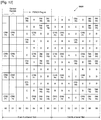
- FIGURE 5 illustrates a resource block (RB) in a 3GPP LTE system according to an exemplary embodiment of the prior art.
- downlink (DL) power allocation indicates to a UE (or MS) an EPRE map that may be assumed for the purpose of demodulation for each cell-specific antenna port (or cell-specific reference signal (RS) port or CRS port).
- RS cell-specific reference signal
- FIGURE 5 illustrates an exemplary EPRE map for a resource block (RB) in Release 8.
- the resource block in FIGURE 5 depicts part of a physical downlink shared channel (PDSCH) of a subframe.
- the horizontal axis indicates time.
- the vertical axis indicates frequency.
- each OFDM symbol is aligned vertically.
- the squares in each vertical column represent different subcarrier frequencies that are part of the same OFDM symbol.
- the squares in each horizontal row represent the same subcarrier frequency in different OFDM symbols.
- each square represents a time-frequency resource element (RE) that may be individually modulated to transmit information.
- RE time-frequency resource element
- Each OFDM symbol comprises N sequential subcarriers, where N may be, for example, 512, 1024, 2048, and so forth.
- each subcarrier may be individually modulated.
- the exemplary RB spans an exemplary one (1) millisecond subframe, where each subframe comprises two (2) slots, each equal to 0.5 milliseconds in duration.
- the subframe contains 14 sequential OFDM symbols, so that each slot contains 7 sequential OFDM symbols.
- the 7 OFDM symbols in each slot are labeled S0, S1, S2, S3, S4, S5, and S6.
- the slots may be greater than or less than 0.5 milliseconds in duration and a subframe may contain more than or less than 14 OFDM symbols.
- the resource block spans 12 sequential subcarriers in the frequency dimension and 14 OFDM symbols in the time dimension.
- the RB contains 168 time-frequency resources.
- the RB may span more than or less than 12 subcarriers and more than or less than 14 OFDM symbols, so that the total number of resource elements (REs) in the RB may vary.
- the subcarriers labeled CRS P0, CRS P1, CRS P2, and CRS P3 represent cell-specific reference signals (e.g., pilot signals) for a particular antenna port.
- CRS P0 is the cell-specific reference signal (CRS) for antenna port 0.
- CRS cell-specific reference signal
- the EPRE for each of CRS P0, CRS P1, CRS P2, and CRS P3 is the value, P.
- the data EPRE values in FIGURE 5 are denoted by letters A and B, depending on type of OFDM symbols on which data EPREs are located.
- a data resource element (RE) is located in an OFDM symbol that does not contain a CRS resource element (RE)
- the EPRE is denoted by the value, A.
- OFDM symbol S3 in the even-numbered slot in FIGURE 5 does not contain a CRS RE, therefore each data RE in OFDM symbol S3 is labeled A.
- the EPRE is denoted by the value, B.
- OFDM symbol S4 in the even-numbered slot in FIGURE 5 does contain CRS REs, therefore each data RE in OFDM symbol S4 is labeled B.
- a Release 8 base station signals three parameters to a UE (or MS) to indicate to the UE the EPRE map associated with the UE, including two cell-specific parameters and one UE-specific parameter.
- the demodulation reference signal may also be called the dedicated RS (DRS) or UE-specific RS (UE-RS).
- DRS is transmitted by the base station (or eNodeB) and is used for demodulation by the UE.
- a DRS for a data stream (or layer) is precoded with the same precoding vector that is used for precoding the data stream.
- FIGURES 6-8 illustrate 2 DRS patterns and 4 DRS patterns in resource blocks according to exemplary embodiments of the prior art.
- Resource block (RB) 500A in FIGURE 6 depicts Rank-2 DRS Pattern A for a pilot signal pattern that can support up to 2 layer transmissions.
- Resource block (RB) 500B in FIGURE 7 depicts Rank-2 DRS Pattern B for a pilot signal pattern that can support up to 2 layer transmissions.
- the reference signals for the two layers are code-division multiplexed within a pair of two adjacent DRS resource elements.
- each instance of two adjacent resource elements labeled DRS P7,8 indicates code-division multiplexed DRS REs for antenna port 7 and antenna port 8.
- each instance of two adjacent resource elements labeled DRS P9,10 indicates code-division multiplexed DRS REs for antenna port 9 and antenna port 10.
- Resource block 500C in FIGURE 8 depicts a DRS pattern that supports up to four layer transmissions, where DRS resource elements are partitioned into two groups.
- One group of DRS REs carries the code-division multiplexed dedicated reference signals (DRSs) for antenna ports 7 and 8 (for layers 0 and 1).
- the other group of DRS REs carries the code-division multiplexed dedicated reference signals (DRSs) for antenna ports 9 and 10 (for layers 2 and 3).
- FIGURES 9 and 10 illustrate 8 DRS patterns based on DRS code-division multiplexing in resource blocks according to exemplary embodiments of the prior art.
- some resource element (RE) are labeled with one of the alphabet characters G, H, I, J, L, or K, to indicate the RE is used to carry a number of DRS among the 8 DRS.
- Resource block (RB) 600A in FIGURE 9 depicts Rank-8 pattern A, which is based on spreading factor 2 code-division multiplexing (CDM) across two time-adjacent REs with the same alphabet label.
- Resource block (RB) 600B in FIGURE 10 depicts Rank-8 pattern B, which is based on spreading factor 4 code-division multiplexing across two groups of two time-adjacent REs with the same alphabet label.
- the 8 antenna ports in the Rank-8 patterns in FIGURES 9 and 10 are referred to as antenna ports 11 through 18 to distinguish the Rank-8 patterns from the antenna ports in the Rank-2 and Rank-4 pattern.
- the two adjacent resource elements labeled DRS G carry the CDMed DRS 11, 12.
- the two adjacent resource elements labeled DRS H carry the CDMed DRS 13, 14.
- the two adjacent resource elements labeled DRS I carry the CDMed DRS 15, 16.
- the two adjacent resource elements labeled DRS J carry the CDMed DRS 17, 18.
- the two adjacent resource elements labeled DRS K carry the CDMed DRS 11, 12, 13, 14.
- the two adjacent resource elements labeled DRS L carry the CDMed DRS 15, 16, 17, 18.
- Higher-layer signaling includes broadcast signaling and RRC signaling, which can be semi-static signaling. Broadcast signaling lets the UEs know cell-specific information, while RRC signaling lets the UEs know UE-specific information.
- Physical-layer signaling includes dynamic signaling, where the dynamic signaling may happen in a physical downlink control channel (PDCCH) in those subframes where the BS or eNodeB wants to transmit signals to the Ms (or UE).
- a downlink control information (DCI) format may be defined, where DCI is transmitted in the PDCCH.
- a transport block is a bit stream carried from a higher layer.
- a TB is mapped into a codeword (CW).
- CW codeword
- up to two TBs (and thus up to two CWs) can be scheduled to a UE in a set of time-frequency resources in a subframe.
- a channel-state-information reference signal (CSI-RS) mapping pattern is defined as a set of resource elements (REs) in one resource block (RB) spanning two slots (or one subframe), where the pattern repeats in every RB in a subset or in the set of RBs in the system bandwidth.
- CSI-RS resource elements may reside in only one slot or in both slots in a RB in one subframe.
- a CSI-RS mapping pattern is provided for estimating channel state information at the receiver side for multiple transmit (Tx) antenna port channels.
- CSI may include channel quality information (CQI), rank information (RI), precoding matrix information (PMI), channel direction information (CDI), and so forth.
- FIGURE 11 illustrates an example of CSI-RS mapping in subframes in a radio frame.
- CSI-RS resources elements i.e., subframes where CSI-RSs are transmitted
- FIGURE 11 illustrates an example of CSI-RS mapping in subframes in a radio frame.
- a Type A subframe does not contain CSI-RS, but does contain CRS in the PDSCH region.
- Subframe 0 (SF0), Subframe 1 (SF1), Subframe 3 (SF3), Subframe 5 (SF5), Subframe 8 (SF8) and Subframe 9 (SF9) are Type A subframes.
- the user equipment uses the CSI-RS resource elements and the CRS resource elements (among others) to determine and to report back to a wireless network at least one of CQI, PMI, modulation scheme, and transport block (TB) size. It is noted that in a given network, not all four types of subframe may be present. Therefore, CSI-RS and CRS resource elements may not be present in certain subframe (SF) types. Thus, interpretation of the feedback data (i.e., CQI, PMI, modulation scheme, TB size) is dependent on the type of subframe the MS/UE receives.
- the prior art does not provide a mobile station (or UE) that considers the subframe (SF) type when determining CQI, PMI, and other feedback parameters.
- the prior art also does not provide a base station that interprets feedback parameters based on the SF type assumed by the MS/UE when determining the feedback parameters.
- SF subframe
- a primary object to provide a base station for use in a wireless network capable of communicating with a plurality of mobile stations.
- the base station transmits to a first mobile station downlink subframes of OFDM symbols.
- Each downlink subframe comprises a plurality of resource blocks and is associated with a subframe (SF) type that is determined according to whether or not a PDSCH region of a resource block in a downlink subframe includes at least one of: 1) a cell-specific reference signal (CRS) resource element and 2) a channel-state-information reference signal (CSI-RS) resource element.
- SF subframe
- the base station receives from the first mobile station at least one of CQI, PMI, modulation scheme, and transport block size and interprets the received at least one of CQI, PMI, modulation scheme, and transport block size according to a default SF type used by the first mobile station to determine the at least one of CQI, PMI, modulation scheme, and transport block size.
- the mobile station receives from a first base station downlink subframes of OFDM symbols.
- Each downlink subframe comprises a plurality of resource blocks and is associated with a subframe (SF) type that is determined according to whether or not a PDSCH region of a resource block in a downlink subframe includes at least one of: 1) a cell-specific reference signal (CRS) resource element and 2) a channel-state-information reference signal (CSI-RS) resource element.
- CRS cell-specific reference signal
- CSI-RS channel-state-information reference signal
- the invention improve apparatuses and methods that account for SF type in the determination and interpretation of feedback parameters.
- FIGURES 1 through 22 discussed below, and the various embodiments used to describe the principles of the present disclosure in this patent document are by way of illustration only and should not be construed in any way to limit the scope of the disclosure. Those skilled in the art will understand that the principles of the present disclosure may be implemented in any suitably arranged wireless network.
- FIGURE 1 illustrates exemplary wireless network 100, which transmits channel state information (CSI) according to the principles of the present disclosure.
- wireless network 100 includes base station (BS) 101, base station (BS) 102, and base station (BS) 103.
- Base station 101 communicates with base station 102 and base station 103.
- Base station 101 also communicates with Internet protocol (IP) network 130, such as the Internet, a proprietary IP network, or other data network.
- IP Internet protocol
- Base stations 101-103 may alternatively be referred to as eNodeBs 101-103.
- Base station 102 provides wireless broadband access to IP network 130 (i.e., the Internet) to a first plurality of mobile stations within coverage area 120 of base station 102.
- BS 102 has a wireline backhaul to IP network 130.
- the first plurality of mobile stations includes mobile station (MS) 111, mobile station (MS) 112, mobile station (MS) 113, mobile station (MS) 114, mobile station (MS) 115 and mobile station (MS) 116.
- MS 111 may be located in a small business (SB), MS 112 may be located in an enterprise (E), MS 113 may be located in a WiFi hotspot (HS), MS 114 may be located in a first residence (R), MS 115 may be located in a second residence, and MS 116 may be a mobile (M) device.
- SB small business
- E enterprise
- E enterprise
- HS WiFi hotspot
- R first residence
- MS 116 may be a mobile (M) device.
- Mobile stations 111-116 may alternatively be referred to as user equipment 111-116.
- Base station 103 provides wireless broadband access to IP network 130 to a second plurality of mobile stations within coverage area 125 of base station 103.
- BS 103 has a wireless backhaul to IP network 130.
- the second plurality of mobile stations includes mobile station 115 and mobile station 116.
- wireless network 100 may include either fewer or more base stations. It is noted that mobile station 115 and mobile station 116 are on the edge of both coverage area 120 and coverage area 125. Mobile station 115 and mobile station 116 each communicate with both base station 102 and base station 103 and may be said to be operating in handoff mode, as known to those of skill in the art.
- base stations 101-103 may communicate with each other and with mobile stations 111-116 in at least the downlink using orthogonal frequency division multiplexing (OFDM) protocol, according to the proposed 3GPP LTE standard, or an equivalent advanced 3G or 4G standard.
- OFDM orthogonal frequency division multiplexing
- Dotted lines show the approximate extents of coverage areas 120 and 125, which are shown as approximately circular for the purposes of illustration and explanation only. It should be clearly understood that the coverage areas associated with base stations, for example, coverage areas 120 and 125, may have other shapes, including irregular shapes, depending upon the configuration of the base stations and variations in the radio environment associated with natural and man-made obstructions.
- the coverage areas associated with base stations are not constant over time and may be dynamic (expanding or contracting or changing shape) based on changing transmission power levels of the base station and/or the mobile stations, weather conditions, and other factors.
- the radius of the coverage areas of the base stations for example, coverage areas 120 and 125 of base stations 102 and 103 may extend in the range from less than 2 kilometers to about fifty kilometers from the base stations.
- a base station may employ directional antennas to support a plurality of sectors within the coverage area.
- base stations 102 and 103 are depicted approximately in the center of coverage areas 120 and 125, respectively.
- the use of directional antennas may locate the base station near the edge of the coverage area, for example, at the point of a cone-shaped or pear-shaped coverage area.
- FIGURES 2 and 3 are high-level diagrams of exemplary base station (eNodeB) 102 according to one embodiment of present disclosure.
- BS 102 comprises transmit path circuitry 200 and receive path circuitry 250.
- Transmit path circuitry 200 comprises channel coding and modulation block 205, serial-to-parallel (S-to-P) block 210, Size N Inverse Fast Fourier Transform (IFFT) block 215, parallel-to-serial (P-to-S) block 220, add cyclic prefix block 225, and up-converter (UC) 230.
- S-to-P serial-to-parallel
- IFFT Size N Inverse Fast Fourier Transform
- P-to-S parallel-to-serial
- UC up-converter
- Receive path circuitry 250 comprises down-converter (DC) 255, remove cyclic prefix block 260, serial-to-parallel (S-to-P) block 265, Size N Fast Fourier Transform (FFT) block 270, parallel-to-serial (P-to-S) block 275, and channel decoding and demodulation block 280.
- DC down-converter
- S-to-P serial-to-parallel
- FFT Size N Fast Fourier Transform
- P-to-S parallel-to-serial
- FIGURES 2 and 3 may be implemented in software while other components may be implemented by configurable hardware or a mixture of software and configurable hardware.
- the FFT blocks and the IFFT blocks described in this disclosure document may be implemented as configurable software algorithms, where the value of Size N may be modified according to the implementation.
- Serial-to-parallel block 210 converts (i.e., de-multiplexes) the serial QAM symbols to parallel data to produce N parallel symbol streams where N is the IFFT/FFT size used in transmit path circuitry 200 and receive path circuitry 250.
- Size N IFFT block 215 then performs an IFFT operation on the N parallel symbol streams to produce time-domain output signals.
- Parallel-to-serial block 220 converts (i.e., multiplexes) the parallel time-domain output symbols from Size N IFFT block 215 to produce a serial time-domain signal.
- Add cyclic prefix block 225 then inserts a cyclic prefix to the time-domain signal.
- up-converter 230 modulates (i.e., up-converts) the output of add cyclic prefix block 225 to RF frequency for transmission via a wireless channel.
- the signal may also be filtered at baseband before conversion to RF frequency.
- the time-domain output transmitted by transmit path circuitry 200 may be transmitted via multiple antennas to mobile stations within range of BS 102.
- Receive path circuitry 250 receives incoming downlink signals transmitted by mobile stations 111-116.
- Down-converter 255 down-converts the received signal to baseband frequency and remove cyclic prefix block 260 removes the cyclic prefix to produce a serial time-domain baseband signal.
- Serial-to-parallel block 265 converts the time-domain baseband signal to parallel time domain signals.
- Size N FFT block 270 then performs an FFT algorithm to produce N parallel frequency-domain signals.
- Parallel-to-serial block 275 converts the parallel frequency-domain signals to a sequence of modulated data symbols.
- Channel decoding and demodulation block 280 demodulates and decodes the date symbols to recover the original data streams transmitted by mobile stations 111-116.
- BS 102 will transmit four types of downlink subframes, depending on whether CSI-RS resource elements and CRS resource elements are transmitted in the physical data shared channel (PDSCH) region or not.
- a new transmission mode (denoted Transmission Mode A) is defined that relies solely on CSI-RS for channel measurement (e.g., CQI/PMI). Since there are four types of subframes, a CQI value may be dependent on a type of subframes that a MS or UE assumes for calculating the CQI value.
- a CQI reference resource i.e., what type of resource to assume in the UE for CQI/PMI calculation
- a CQI reference resource is defined for the new Transmission Mode A to avoid mistake and to assist link adaptation at the eNodeB.
- Transmission Mode A A first exemplary definition of Transmission Mode A is shown below in TABLE 1.
- the PDCCH and the PDSCH are configured by the scrambling sequence C-RNTI.
- TABLE 1 Transmission mode DCI format Search Space Transmission scheme of PDSCH corresponding to PDCCH Mode A DCI for mat 1A Common and U E-specific b y C-RNTI If the number of PBCH an tenna ports is one, Sing le-antenna port, port 0 is used, otherwise Trans mit diversity.
- a second exemplary definition of Transmission Mode A is shown below in TABLE 2.
- the PDCCH and the PDSCH are configured by the scrambling sequence SPS C-RNTI.
- TABLE 2 Transmiss ion mode
- DCI format Search Space Transmission scheme of PDSCH corresponding to PDCCH Mode A DCI form at 1A Common and U E-specific b y C-RNTI If the number of PBCH ant enna ports is one, Single -antenna port, port 0 is used, otherwise Transmit diversity.
- DCI form at 2C UE-specific by C-RNTI Single antenna port; port 7 or 8 or 9 or 10.
- the R S patterns for the antenn a ports can be found in F igures 5A-5C.
- FIGURE 4 illustrates mobile station (or user equipment) 116, which receives channel state information (CSI) according to an exemplary embodiment of the disclosure.
- MS 116 comprises transceiver block 310, message processor 320, and CQI/PMI calculation block 330.
- message processor 320 uses transceiver block 310 to transmit to, for example, BS 102 and to receive from BS 102.
- Transceiver block 310 comprises circuit components that are analogous to the components in transmit path circuitry 200 and receive path circuitry 250 in BS 102 and need not be explained in further detail.
- CQI/PMI calculation block 330 receives downlink signal measurements from transceiver block 310 and is operable to determine therefrom CQI values and PMI values, among other signal parameters, for the downlink between BS 102 and MS 116.
- Message processor 320 may receive selected CQI value, PMI values and other selected signal parameters from CQI/PMI calculation block 330 and is operable to transmit control messages and data messages in the uplink to BS 102.
- message processor 320 is operable to transmit feedback messages to BS 102 to report CQI values and PMI values.
- FIGURES 12-15 illustrate four types of EPRE maps for four cell-specific antenna ports according to an exemplary embodiment of the present disclosure.
- the resource elements labeled "CRS P0", “CRS P1", “CRS P2” and “CRS P3” are for cell-specific reference signals (CRSs) for the four antenna ports, P0-P3.
- the resource elements labeled “CSI-RS” are resource elements for channel-state-information reference signals.
- the resource elements labeled "DM-RS” are resource elements for demodulation reference signals.
- Resource block (RB) 800A has both CSI-RS resource elements and CRS resource elements.
- Resource block (RB) 800B has CSI-RS resource elements, but does not have CRS resource elements.
- Resource block (RB) 800C does not have CSI-RS resource elements, but does have CRS resource elements.
- Resource block (RB) 800D has neither CSI-RS resource elements nor CRS resource elements.
- each new cell-specific antenna port (or each CSI-RS port).
- the EPRE for each of CRS P0, CRS P1, CRS P2, and CRS P3 (i.e., the antenna ports) is the value P; 2) the EPRE for each of the DM-RS resource elements is the value D; and 3) the EPRE for each of the CSI-RS resource elements is the value Q.
- a resource block (RB) without a CRS is from an advanced (or Release 10) subframe configured as MBSFN subframe to Release 8 UEs.
- CRSs are transmitted only in the control region.
- a base station signals parameters conveying information about these EPREs to each MS via cell-specific and MS-specific signaling methods. Upon receiving the parameters, a MS becomes aware of these four EPRE maps.
- FIGURES 16-19 illustrate four types of EPRE maps for two cell-specific antenna ports according to an exemplary embodiment of the present disclosure. Since only two antenna ports are provided, resource blocks 900A-800D contain only two resource elements, labeled "CRS P0" and “CRS P1", for cell-specific reference signals (CRSs) for only two antenna ports, P0 and P1. As before, in FIGURE 12-15 , the resource elements labeled “CSI-RS” are resource elements for channel-state-information reference signals. The resource elements labeled "DM-RS" are resource elements for demodulation reference signals.
- CRS P0 cell-specific reference signals
- a MS/UE assumes one specific type of subframe (a pre-determined SF type or default SF type), out of the four types shown in FIGURE 11 , as a part of CQI reference resource for CQI/PMI estimation for new Transmission Mode A.
- the MS/UE further assumes for each CSI-RS port, the per-RB EPRE map follows the EPRE map in FIGURES 12-15 and FIGURES 16-19 associated with that type of subframe.
- a MS/UE assumes the subframe type without a CSI-RS, but with a CRS in the PDSCH region for CQI/PMI estimation.
- Section 7.2.3 of 3GPP TS No. 36.213 may be modified so that the CQI reference resource is defined in the frequency domain by the group of downlink physical resource blocks corresponding to the band to which the derived CQI value relates.
- a downlink subframe would be considered to be valid if: 1) it is configured as a downlink subframe for that UE, 2) it is not an MBSFN subframe, 3) it does not contain a DwPTS field if the length of DwPTS is 7680TS or less, 4) is does not fall within a configured measurement gap for that US; and 5) it does contain a CSI-RS. If there is no valid downlink subframe for the CQI reference resource, CQI reporting is omitted in uplink subframe n
- a MS/UE assumes resource blocks (RBs) without a CSI-RS and without a CRS for CQI/PMI estimation.
- RBs resource blocks
- MMSFN multicast-broadcast single frequency network
- a downlink subframe is considered to be valid to be a CQI reference resource if the downlink subframe is an advanced (or Release 10) subframe without a CSI-RS.
- MCSFN multicast-broadcast single frequency network
- a downlink subframe is considered to be valid to be a CQI reference resource if the downlink subframe is an advanced (or Release 10) subframe without a CSI-RS.
- an MS/UE may further assume that the first two OFDM symbols are occupied by control signaling, instead of 3 OFDM symbols which had been a case for subframes with a CRS.
- the BS/eNodeB signals to the MS/UE to indicate a specific type of subframe (a pre-determined SF type or default SF type) for CQI reference resource purposes.
- the number of states is limited to two subframe types without CSI-RS, and the signaling may be either MS-specific or cell-specific. The two states in this example are shown below in TABLE 3.
- the two-state signaling may be conveyed in a one-bit field in a higher layer.
- a MS/UE assumes the presence of DM-RS in a default type subframe for the purpose of deriving the CQI index value. That is, the CQI index is calculated assuming that, in the CQI reference resource, the number and the position of DM-RS resource elements are known and taken into account in calculating CQI index by assuming these locations are occupied by user equipment reference signals (UE-RS).
- UE-RS user equipment reference signals
- the number and the location of DM-RS resource elements assumed for deriving the CQI index are dependent on the rank feedback (RI) at an MS/UE on which the CQI is conditioned.
- An MS/UE transmits a PUCCH report in the uplink to send control information to the BS/eNodeB.
- a PUCCH report may send CQI information or RI information, but not both.
- the CQI calculation and report is conditioned on the RI value from the latest PUCCH report that contains an RI report.
- An MS/UE normally transmits a PUSCH report in the uplink to send data information to the BS/eNodeB.
- a PUSCH report may sometimes send CQI information, RI information, or both to a BS/eNodeB by multiplexing the control information with the data information.
- the CQI calculation and report is conditioned on the RI value that accompanies the CQI in the same PUSCH report.
- FIGURES 20 and 21 illustrate an example of rank-dependent EPRE mapping for the case of a subframe type without CSI-RS and with CRS in the PDSCH region.
- an MS/UE estimates the transmission rank is less than or equal to 2
- the MS/UE assumes the 12 resource element DM-RS pattern in FIGURE 21 .
- the MS/UE assumes the 24 resource element DM-RS pattern in FIGURE 20 .
- Section 7.2.3 of 3GPP TS No. 36.213 may be modified, for Release 10 or later transmission modes, so that, in the CQI reference resource, the MS/UE may assume the following for the purpose of deriving the CQI index: 1) the first 3 OFDM symbols are occupied by control signaling, 2) no resource elements are used by primary or secondary synchronization signals or PBCH, 3) the CP length of the non-MBSFN subframes, 4) redundancy version 0, 5) the PDSCH transmission scheme given by Table 7.2.3-0 depending on the transmission mode currently configured for the UE (which may be the default mode).
- UE-specific RS REs for antenna ports 7 and 8 are occupied by UE-specific RS. Also, if the estimated rank is greater than 2, UE-specific RS REs for antenna ports 7, 8, 9 and 10 are occupied by UE-specific RS.
- the base station may semi-statically configure a specific rank-dependent DM-RS pattern for the purpose of deriving the CQI index, or for the purpose of MS/ UE demodulation, or both.
- the specific DM-RS pattern determines the number and the location of the DM-RS resource elements that are assumed for CQI calculation.
- the BS may configure the MS/UE to assume the DM-RS pattern (24 resource element pattern) in FIGURE 20 for the purpose of deriving CQI index.
- the BS may also configure the MS/UE to assume the DM-RS pattern (12 resource pattern) in FIGURE 21 for the purpose of deriving CQI index.
- Section 7.2.3 of 3GPP TS No. 36.213 may be modified, for Rel-10 or later transmission modes, so that in the CQI reference resource, the UE shall assume the following for the purpose of deriving the CQI index: 1) the first 3 OFDM symbols are occupied by control signaling, 2) no resource elements used by primary or secondary synchronization signals or PBCH, 3) CP length of the non-MBSFN subframes, 4) Redundancy Version 0, 5) the PDSCH transmission scheme given by Table 7.2.3-0 depending on the transmission mode currently configured for the UE (which may be the default mode), and 6) if a UE-specific RS pattern is signaled, the UE-specific RS pattern that is signaled to the UE by the eNB is occupied by UE-RS.
- one particular DM-RS pattern may be assumed for CQI calculation.
- a transmission mode with two different DM-RS patterns, a rank-4 pattern and a rank-2 pattern is shown in FIGURES 10A and 10B .
- an MS/UE may calculate the CQI value assuming the DM-RS pattern in FIGURE 21 , regardless of the transmission rank the MS/UE estimates.
- Section 7.2.3 of 3GPP TS No. 36.213 may be modified, for Release 10 or later transmission modes, so that, in the CQI reference resource, the UE shall assume the following for the purpose of deriving the CQI index: 1) the first 3 OFDM symbols are occupied by control signaling, 2) no resource elements used by primary or secondary synchronization signals or PBCH, 3) CP length of the non-MBSFN subframes, 4) Redundancy Version 0, 5) the PDSCH transmission scheme given by Table 7.2.3-0 depending on the transmission mode currently configured for the UE (which may be the default mode), and 6) if a UE is configured in a transmission mode with a set of rank-dependent DM RS patterns, UE-specific RS REs for antenna ports 7, 8, 9 and 10 are occupied by UE-specific RS.
- FIGURE 22 illustrates the DM-RS pattern for a 3GPP LTE system in Release 9.
- Transmission mode 8 is defined for Release 9 LTE transmissions supporting dual-layer beamforming (up to rank 2 or a maximum of two streams for a MS/UE) and utilizing two DM-RS ports, namely, antenna ports 7 and 8.
- Mobile stations in transmission mode 8 use CRS resource elements to estimate CQI, PMI, and RI.
- CQI reporting mode 8 There are two modes of CQI reporting for transmission mode 8: 1) CQI reporting mode 1 - TxD-based CQI without PMI/RI reporting, and 2) CQI reporting mode 2 - CQI reporting based on closed-loop spatial multiplexing with PMI/RI reporting configured.
- the MS/UE may exclude DM-RS resource elements for CQI calculation.
- Section 7.2.3 of 3GPP TS No. 36.213 may be modified for transmission mode 8 so that, in the CQI reference resource, the UE shall assume the following for the purpose of deriving the CQI index: 1) the first 3 OFDM symbols are occupied by control signaling, and 2) for a UE in transmission mode 8, the UE-specific RS pattern as defined for antenna port 7 and 8 in non-DwPTS subframe are occupied for UE-RS.
- Section 7.2.3 of 3GPP TS No. 36.213 may be modified so that in the CQI reference resource, the MS/UE may assume the following for the purpose of deriving the CQI index: 1) the first 3 OFDM symbols are occupied by control signaling, and 2) for a UE in transmission mode 8 configured with PMI/CQI reporting, the UE-specific RS pattern as defined for antenna port 7 and 8 in non-DwPTS subframes are occupied for UE-RS.
Landscapes
- Engineering & Computer Science (AREA)
- Signal Processing (AREA)
- Computer Networks & Wireless Communication (AREA)
- Quality & Reliability (AREA)
- Mobile Radio Communication Systems (AREA)
Claims (14)
- Procédé pour dériver un indicateur de qualité de canal, CQI, par un équipement d'utilisateur, UE, dans un système de communication sans fil, le procédé comprenant les étapes consistant à :recevoir au moins l'un parmi un signal de référence spécifique à la cellule, CRS, ou un signal de référence d'informations d'état de canal , CSI-RS, dans une sous-trame de liaison descendante ; etdériver des CQI sur la base de la réception de l'au moins l'un parmi le CRS ou le CSI-RS dans la sous-trame de liaison descendante, et une ressource de référence de CQI ; ettransmettre les CQI à un nœud B évolué, eNB,où la ressource de référence de CQI est définie par un groupe de blocs de ressources physiques de liaison descendante correspondant à la bande à laquelle se rapportent les CQI dérivées, et la sous-trame de liaison descendante.
- Procédé selon la revendication 1, où, dans la ressource de référence de CQI, l'UE suppose qu'un surdébit de DMRS, signal de référence de démodulation, est cohérent avec le rang le plus récent rapporté.
- Procédé selon la revendication 1, où, dans la ressource de référence de CQI, l'UE suppose qu'aucun RE, élément de ressource, n'est attribué à des CSI-RS ni à des CSI-RS de puissance nulle.
- Procédé selon la revendication 1, où la sous-trame de liaison descendante est considérée comme étant valable si la sous-trame de liaison descendante est configurée comme une sous-trame de liaison descendante pour l'UE, la sous-trame de liaison descendante n'est pas une sous-trame de MBSFN, réseau de diffusion/multidiffusion à fréquence unique, la sous-trame de liaison descendante ne contient pas de champ de DwPTS, intervalle de temps de pilote de liaison descendante : DwPTS, dans le cas où la longueur de DWPTS serait de 7680TS ou inférieure, et la sous-trame de liaison descendante ne se situerait pas dans un écart de mesure configuré pour l'UE.
- Procédé selon la revendication 2, où l'UE suppose que le surdébit de DMRS est cohérent avec le rang le plus récent rapporté, si l'UE est configuré pour un rapport de PMI/RI, indicateur de matrice de précodage / indicateur de rang,où le rang le plus récent rapporté est inférieur ou égal à 2, le surdébit de DMRS est le surdébit de RE pour les ports d'antenne 7 et 8, etoù le rang le plus récent rapporté est supérieur à 2, le surdébit de DMRS est le surdébit de RE pour les ports d'antenne 7, 8, 9 et 10.
- Procédé pour recevoir un indicateur de qualité de canal, CQI, par un nœud B évolué, eNB, dans un système de communication sans fil, le procédé comprenant les étapes consistant à :transmettre au moins l'un parmi un signal de référence spécifique à la cellule, CRS, ou un signal de référence d'informations d'état de canal, CSI-RS, dans une sous-trame de liaison descendante ; etrecevoir des CQI sur la base de la transmission d'au moins l'un parmi le CRS ou le CSI-RS dans la sous-trame de liaison descendante, et une ressource de référence de CQI à partir d'un équipement d'utilisateur, UE,où la ressource de référence de CQI est définie par un groupe de blocs de ressources physiques de liaison descendante correspondant à la bande à laquelle les CQI reçues se rapportent, et la sous-trame de liaison descendante.
- Procédé selon la revendication 6, où, dans la ressource de référence de CQI, l'UE suppose qu'un surdébit de DMRS, signal de référence de démodulation, est cohérent avec le rang le plus récent rapporté.
- Procédé selon la revendication 6, où, dans la ressource de référence de CQI, l'UE suppose qu'aucun RE, élément de ressource, n'est attribué à des CSI-RS ni à des CSI-RS de puissance nulle.
- Procédé selon la revendication 6, où la sous-trame de liaison descendante est considérée comme étant valable si la sous-trame de liaison descendante est configurée comme une sous-trame de liaison descendante pour l'UE, la sous-trame de liaison descendante n'est pas une sous-trame de MBSFN, réseau de diffusion/multidiffusion à fréquence unique, la sous-trame de liaison descendante ne contient pas de champ de DwPTS, intervalle de temps de pilote de liaison descendante: DwPTS, dans le cas où la longueur de DwPTS serait de 7680TS ou inférieure, et la sous-trame de liaison descendante ne se situerait pas dans un écart de mesure configuré pour l'UE.
- Procédé selon la revendication 7, où l'UE suppose que le surdébit de DMRS est cohérent avec le rang le plus récent rapporté, si l'UE est configuré pour un rapport de PMI/RI, indicateur de matrice de précodage/indicateur de rang,où le rang le plus récent rapporté est inférieur ou égal à 2, le surdébit de DMRS est le surdébit de RE pour les ports d'antenne 7 et 8, etoù le rang le plus récent rapporté est supérieur à 2, le surdébit de DMRS est le surdébit de RE pour les ports d'antenne 7, 8, 9 et 10.
- UE, équipement d'utilisateur, pour dériver un indicateur de qualité de canal, CQI, dans un système de communication sans fil, l'UE comprenant :un émetteur-récepteur (310) ; etun processeur (320, 330) couplé à l'émetteur-récepteur et configuré pour :recevoir au moins l'un parmi un signal de référence spécifique à la cellule, CRS, ou un signal de référence d'informations d'état de canal, CSI-RS, dans une sous-trame de liaison descendante ;dériver des CQI sur la base de la réception de l'au moins l'un parmi le CRS ou le CSI-RS dans la sous-trame de liaison descendante, et une ressource de référence de CQI ; ettransmettre les CQI à un nœud B évolué, eNB,où la ressource de référence de CQI est définie par un groupe de blocs de ressources physiques de liaison descendante correspondant à la bande à laquelle la valeur de CQI dérivée se rapporte, et la sous-trame de liaison descendante.
- UE selon la revendication 11, où l'UE est configuré pour mettre en œuvre au moins l'une des revendications 2 à 5.
- ENB, nœud B évolué, pour recevoir un indicateur de qualité de canal, CQI, dans un système de communication sans fil, l'eNB comprenant :un émetteur-récepteur ; etun processeur couplé à l'émetteur-récepteur et configuré pour :transmettre au moins l'un parmi un signal de référence spécifique à la cellule, CRS, ou un signal de référence d'informations d'état de canal, CSI-RS, dans une sous-trame de liaison descendante, etrecevoir des CQI sur la base de la transmission d'au moins l'un parmi le CRS ou le CSI-RS dans la sous-trame de liaison descendante, et une ressource de référence de CQI à partir d'un équipement d'utilisateur, UE,où la ressource de référence de CQI est définie par un groupe de blocs de ressources physiques de liaison descendante correspondant à la bande à laquelle les CQI reçues se rapportent, et la sous-trame de liaison descendante.
- ENB selon la revendication 13, où l'eNB est configuré pour mettre en œuvre la revendication 9.
Applications Claiming Priority (3)
| Application Number | Priority Date | Filing Date | Title |
|---|---|---|---|
| US28415509P | 2009-12-14 | 2009-12-14 | |
| US12/945,585 US8824384B2 (en) | 2009-12-14 | 2010-11-12 | Systems and methods for transmitting channel quality information in wireless communication systems |
| PCT/KR2010/008604 WO2011074807A2 (fr) | 2009-12-14 | 2010-12-02 | Systèmes et procédés permettant de transmettre des informations de qualité de canal dans des systèmes de communication sans fil |
Publications (3)
| Publication Number | Publication Date |
|---|---|
| EP2514237A2 EP2514237A2 (fr) | 2012-10-24 |
| EP2514237A4 EP2514237A4 (fr) | 2017-06-28 |
| EP2514237B1 true EP2514237B1 (fr) | 2021-01-27 |
Family
ID=44142815
Family Applications (1)
| Application Number | Title | Priority Date | Filing Date |
|---|---|---|---|
| EP10837803.5A Active EP2514237B1 (fr) | 2009-12-14 | 2010-12-02 | Systèmes et procédés permettant de transmettre des informations de qualité de canal dans des systèmes de communication sans fil |
Country Status (9)
| Country | Link |
|---|---|
| US (2) | US8824384B2 (fr) |
| EP (1) | EP2514237B1 (fr) |
| JP (2) | JP5645962B2 (fr) |
| KR (1) | KR101772242B1 (fr) |
| CN (2) | CN104363071B (fr) |
| AU (1) | AU2010331106B2 (fr) |
| CA (1) | CA2782788C (fr) |
| RU (1) | RU2524867C2 (fr) |
| WO (1) | WO2011074807A2 (fr) |
Families Citing this family (110)
| Publication number | Priority date | Publication date | Assignee | Title |
|---|---|---|---|---|
| US8755807B2 (en) * | 2009-01-12 | 2014-06-17 | Qualcomm Incorporated | Semi-static resource allocation to support coordinated multipoint (CoMP) transmission in a wireless communication network |
| US8599708B2 (en) * | 2010-01-14 | 2013-12-03 | Qualcomm Incorporated | Channel feedback based on reference signal |
| KR101895947B1 (ko) * | 2010-01-18 | 2018-09-07 | 엘지전자 주식회사 | 무선 통신 시스템에서 채널 품질 정보를 제공하는 방법 및 장치 |
| EP3370354B1 (fr) * | 2010-01-28 | 2019-08-28 | LG Electronics Inc. | Procédé et appareil permettant de transmettre un signal par l'intermédiaire d'une liaison de raccordement de relais |
| WO2011096646A2 (fr) | 2010-02-07 | 2011-08-11 | Lg Electronics Inc. | Procédé et appareil pour émettre un signal de référence descendant dans un système de communication sans fil prenant en charge plusieurs antennes |
| CN102215090A (zh) * | 2010-04-02 | 2011-10-12 | 北京三星通信技术研究有限公司 | 一种基于mimo传输发送和接收下行控制信息的方法 |
| US8730903B2 (en) * | 2010-04-22 | 2014-05-20 | Lg Electronics Inc. | Method and apparatus for channel estimation for radio link between a base station and a relay station |
| WO2011132964A2 (fr) * | 2010-04-23 | 2011-10-27 | 엘지전자 주식회사 | Procédé permettant de transmettre/recevoir des signaux entre une station de base et un noeud relais dans un système de communication sans fil à utilisateurs multiples et antennes multiples, et appareil pour ce dernier |
| US9276722B2 (en) * | 2010-05-05 | 2016-03-01 | Qualcomm Incorporated | Expanded search space for R-PDCCH in LTE-A |
| US8780766B2 (en) * | 2010-08-16 | 2014-07-15 | Qualcomm Incorporated | Interleaving for relay physical downlink control channel (R-PDCCH) |
| CN107196718B (zh) | 2010-09-30 | 2020-12-18 | Lg 电子株式会社 | 用于在无线通信系统中通过中继节点报告信道质量指示符的方法及其装置 |
| US9014024B2 (en) * | 2010-10-04 | 2015-04-21 | Qualcomm Incorporated | Devices for determining a reference subframe and determining a mode |
| CN103155672A (zh) * | 2010-10-05 | 2013-06-12 | 诺基亚西门子网络公司 | 信道状态信息测量和报告 |
| CN103262617B (zh) * | 2010-10-09 | 2016-05-04 | 中兴通讯股份有限公司 | 下行链路功率分配的方法 |
| CN102469496B (zh) * | 2010-11-05 | 2014-12-17 | 大唐移动通信设备有限公司 | 一种信道质量信息的上报方法及其装置 |
| KR101944879B1 (ko) * | 2010-11-08 | 2019-02-07 | 삼성전자 주식회사 | 무선통신 시스템에서 서로 다른 형태의 서브프레임을 수신하는 방법 및 장치 |
| CN103299558B (zh) * | 2011-01-07 | 2016-07-06 | 交互数字专利控股公司 | 无线发射/接收单元和由无线发射/接收单元执行的方法 |
| US8761062B2 (en) * | 2011-01-11 | 2014-06-24 | Texas Instruments Incorporated | CSI measurement, reporting and collision-handling |
| CN102595469B (zh) * | 2011-01-12 | 2016-11-16 | 中兴通讯股份有限公司 | 一种信道质量指示信息的确定方法 |
| KR101868626B1 (ko) * | 2011-01-14 | 2018-06-18 | 엘지전자 주식회사 | 무선 통신 시스템에서 채널상태정보 측정 자원 설정 방법 및 장치 |
| US20130294282A1 (en) * | 2011-01-23 | 2013-11-07 | Lg Electronics Inc. | Method and apparatus for transmitting an uplink signal by a relay in a wireless communcation system |
| WO2012129798A1 (fr) | 2011-03-30 | 2012-10-04 | Huawei Technologies Co., Ltd. | Procédé et appareil utilisés pour une transmission en boucle ouverte dans un système de communication sans fils multi-antenne |
| US8948293B2 (en) * | 2011-04-20 | 2015-02-03 | Texas Instruments Incorporated | Downlink multiple input multiple output enhancements for single-cell with remote radio heads |
| JP5396427B2 (ja) * | 2011-05-02 | 2014-01-22 | 株式会社Nttドコモ | 無線基地局装置、ユーザ端末装置、無線通信システム、及び無線通信方法 |
| KR102041189B1 (ko) | 2011-05-03 | 2019-11-07 | 삼성전자 주식회사 | 무선 통신 시스템에서 mbms 서비스를 수신하는 단말이 mbsfn 서브프레임에서 반영구적 스케쥴링 을 처리하는 방법 및 장치 |
| US9319123B2 (en) * | 2011-05-10 | 2016-04-19 | Lg Electronics Inc. | Method for receiving reference signal and user equipment, and method for transmitting reference signal and base station |
| KR20140036247A (ko) * | 2011-06-29 | 2014-03-25 | 엘지전자 주식회사 | 채널상태정보 전송방법 및 사용자 기기, 그리고 채널상태정보 수신방법 및 기지국 |
| KR20140044322A (ko) * | 2011-07-31 | 2014-04-14 | 엘지전자 주식회사 | 무선 접속 시스템에서 채널 품질 측정 방법 및 이를 위한 장치 |
| JP6026415B2 (ja) * | 2011-08-05 | 2016-11-16 | パナソニック インテレクチュアル プロパティ コーポレーション オブ アメリカPanasonic Intellectual Property Corporation of America | 端末、送信装置、受信品質報告方法および受信方法 |
| CN102291211B (zh) * | 2011-08-09 | 2014-02-05 | 电信科学技术研究院 | 一种基于多点协同传输的信息传输方法和设备 |
| MY164105A (en) | 2011-08-12 | 2017-11-30 | Interdigital Patent Holdings Inc | Interference measurement in wireless networks |
| KR101645827B1 (ko) | 2011-08-12 | 2016-08-04 | 인터디지탈 패튼 홀딩스, 인크 | 확장 반송파 및 반송파 세그먼트에 대한 기준 신호 구성 |
| EP2747319B1 (fr) * | 2011-08-16 | 2019-04-17 | LG Electronics Inc. | Procédé permettant à une station de base de multiplexer un canal de commande de liaison descendante dans un système de communication sans fil, et appareil associé |
| US9277513B2 (en) * | 2011-09-05 | 2016-03-01 | Lg Electronics Inc. | Terminal apparatus for controlling downlink transmission power and method for same |
| US8797966B2 (en) | 2011-09-23 | 2014-08-05 | Ofinno Technologies, Llc | Channel state information transmission |
| KR101855523B1 (ko) * | 2011-10-06 | 2018-05-04 | 삼성전자주식회사 | 통신 시스템에서 피드백 생성 방법 및 장치 |
| KR20130038044A (ko) | 2011-10-07 | 2013-04-17 | 삼성전자주식회사 | 이동통신시스템에서 하향링크 채널의 채널상태정보를 송수신하는 방법 및 장치 |
| WO2013055126A1 (fr) * | 2011-10-11 | 2013-04-18 | 엘지전자 주식회사 | Procédé de mesure d'état de la qualité d'un canal dans un système de communication sans fil comportant des cellules formées avec une pluralité de nœuds de réseau, et appareil pour ledit procédé |
| KR20130039644A (ko) * | 2011-10-12 | 2013-04-22 | 삼성전자주식회사 | 통신 시스템에서의 피드백 송수신 방법 및 장치 |
| US9002345B2 (en) | 2011-10-12 | 2015-04-07 | Samsung Electronics Co., Ltd. | Method and apparatus for transmitting and receiving feedback information in a mobile communication system |
| US9787383B2 (en) * | 2011-10-14 | 2017-10-10 | Lg Electronics Inc. | Method and device for transmitting channel state information in wireless communication system |
| JP2014534651A (ja) * | 2011-10-31 | 2014-12-18 | 日本電気株式会社 | Mimo通信システムにおけcsi測定方法及びcsi測定用ユーザー機器 |
| US8848560B2 (en) * | 2011-11-04 | 2014-09-30 | Blackberry Limited | Apparatus and method for adaptive transmission during almost blank subframes in a wireless communication network |
| EP2769591B1 (fr) * | 2011-11-09 | 2016-10-05 | Telefonaktiebolaget LM Ericsson (publ) | Détection de configuration de sous-trame presque vide dans des réseaux hétérogènes |
| US9219994B2 (en) * | 2011-11-09 | 2015-12-22 | Lg Electronics Inc. | Methods for transmitting and receiving downlink data in MBSFN subframe and apparatuses thereof |
| KR101605280B1 (ko) * | 2011-11-25 | 2016-03-21 | 엘지전자 주식회사 | 무선 통신 시스템에서 채널 품질 지시자를 측정하는 방법 및 장치 |
| US9877313B2 (en) * | 2011-11-25 | 2018-01-23 | Lg Electronics Inc. | Method for transmitting downlink control channel by base station in wireless communication system, and device therefor |
| WO2013087024A1 (fr) * | 2011-12-14 | 2013-06-20 | 华为技术有限公司 | Procédé et station de base pour transmettre un signal |
| US9014114B2 (en) * | 2011-12-14 | 2015-04-21 | Qualcomm Incorporated | User equipment reference signal-based timing estimation |
| US8885569B2 (en) | 2011-12-19 | 2014-11-11 | Ofinno Technologies, Llc | Beamforming signaling in a wireless network |
| KR101594377B1 (ko) * | 2012-01-11 | 2016-02-16 | 엘지전자 주식회사 | 참조신호를 이용한 채널 추정 방법 및 장치 |
| JP5783271B2 (ja) * | 2012-02-10 | 2015-09-24 | 日本電気株式会社 | 無線通信システム、基地局、通信方法 |
| US9973955B2 (en) * | 2012-03-16 | 2018-05-15 | Futurewei Technologies, Inc. | Systems and methods for reference signals and CSI feedback |
| JP6081074B2 (ja) * | 2012-03-30 | 2017-02-15 | 株式会社Nttドコモ | 無線通信システム、基地局装置、及び無線通信方法 |
| US9143984B2 (en) * | 2012-04-13 | 2015-09-22 | Intel Corporation | Mapping of enhanced physical downlink control channels in a wireless communication network |
| US9357543B2 (en) * | 2012-04-18 | 2016-05-31 | Lg Electronics Inc. | Method and apparatus for receiving downlink data in wireless communication system |
| AU2013250063B2 (en) | 2012-04-19 | 2017-11-02 | Samsung Electronics Co., Ltd. | Method and apparatus for quasi co-location identification of reference symbol ports for coordinated multi-point communication systems |
| WO2013159317A1 (fr) * | 2012-04-26 | 2013-10-31 | 华为技术有限公司 | Procédé de configuration de mode de transmission et équipement utilisateur et station de base |
| US10003998B2 (en) * | 2012-05-04 | 2018-06-19 | Qualcomm Incorporated | Systems and methods for reduced overhead in wireless communication systems |
| US9473218B2 (en) | 2012-05-10 | 2016-10-18 | Fujitsu Limited | Signaling scheme for coordinated transmissions |
| EP2848059A2 (fr) | 2012-05-10 | 2015-03-18 | Fujitsu Limited | Schéma de signalisation servant à des transmissions coordonnées |
| US9681425B2 (en) * | 2012-05-11 | 2017-06-13 | Qualcomm Incorporated | Rank-specific feedback for improved MIMO support |
| EP3883172A1 (fr) | 2012-06-04 | 2021-09-22 | Interdigital Patent Holdings, Inc. | Communication d'informations d'état de canal (csi) de multiples points de transmission |
| US9591646B2 (en) | 2012-06-12 | 2017-03-07 | Qualcomm Incorporated | Reference signal power impact determination in new carrier type in LTE |
| US20130343300A1 (en) * | 2012-06-21 | 2013-12-26 | Lg Electronics Inc. | Method and apparatus for transmitting and receiving data |
| US9203576B2 (en) * | 2012-08-03 | 2015-12-01 | Telefonaktiebolaget L M Ericsson (Publ) | Quasi co-located antenna ports for channel estimation |
| CN103634084B (zh) * | 2012-08-23 | 2016-12-21 | 华为技术有限公司 | 优化导频的方法及装置 |
| KR101972945B1 (ko) | 2012-09-18 | 2019-04-29 | 삼성전자 주식회사 | 무선 통신 시스템에서 채널 상태 정보 송수신 방법 및 장치 |
| CN104685802B (zh) | 2012-10-04 | 2018-03-23 | Lg电子株式会社 | 在无线通信系统中通过考虑天线端口关系收发下行链路信号的方法和设备 |
| CN104662984B (zh) | 2012-10-25 | 2018-11-06 | Lg 电子株式会社 | 在无线通信系统中收发下行链路信号的方法及其设备 |
| JP6320675B2 (ja) * | 2012-12-03 | 2018-05-09 | 株式会社Nttドコモ | 無線基地局、ユーザ端末及びフェージング周波数推定方法 |
| US9178583B2 (en) * | 2013-01-08 | 2015-11-03 | Samsung Electronics Co., Ltd. | Channel state information feedback design in advanced wireless communication systems |
| CN103974315B (zh) | 2013-02-05 | 2018-01-19 | 电信科学技术研究院 | 三维信道测量资源配置和质量测量方法及设备 |
| WO2014153777A1 (fr) | 2013-03-29 | 2014-10-02 | Nec(China) Co., Ltd. | Procédés et appareils de transmission de données dans un système de communication sans-fil |
| TWI483568B (zh) * | 2013-03-29 | 2015-05-01 | Univ Nat Yunlin Sci & Tech | Multi-input multi-output wireless signal transmission and power control system |
| US9509469B2 (en) * | 2013-04-04 | 2016-11-29 | Futurewei Technologies, Inc. | Device, network, and method for utilizing a downlink discovery reference signal |
| US9900872B2 (en) | 2013-04-17 | 2018-02-20 | Futurewei Technologies, Inc. | Systems and methods for adaptive transmissions in wireless network |
| WO2014182541A2 (fr) | 2013-05-08 | 2014-11-13 | Interdigital Patent Holdings, Inc. | Procédés, systèmes et appareils pour annulation et/ou suppression de brouillage assistée par réseau (naics) dans des systèmes d'évolution à long terme (lte) |
| WO2014190472A1 (fr) | 2013-05-27 | 2014-12-04 | 华为技术有限公司 | Procédé et dispositif de soumission d'informations de mesure de qualité de signal |
| KR101857665B1 (ko) | 2013-08-29 | 2018-05-14 | 엘지전자 주식회사 | 기계타입통신을 지원하는 무선 접속 시스템에서 채널상태정보 전송 방법 및 장치 |
| US10693623B2 (en) | 2014-01-31 | 2020-06-23 | Apple Inc. | Reference subframes for synchronization and cell measurements |
| US10178574B2 (en) * | 2014-05-02 | 2019-01-08 | Lg Electronics Inc. | Method for reporting channel state and device therefor |
| US10321469B2 (en) * | 2014-05-16 | 2019-06-11 | Sharp Kabushiki Kaisha | Terminal device, integrated circuit, and radio communication method |
| EP3205163B1 (fr) * | 2014-10-10 | 2018-09-26 | Telefonaktiebolaget LM Ericsson (publ) | Systèmes et procédés relatifs à une configuration flexible de csi-rs et à un retour associé |
| CN106470096B (zh) | 2015-08-14 | 2021-03-23 | 索尼公司 | 用于无线通信的基站侧和用户设备侧的装置及方法 |
| US10470049B2 (en) | 2015-08-21 | 2019-11-05 | Lg Electronics Inc. | Method for determining valid subframe for non-licensed band in wireless communication system, and apparatus using the method |
| US10554329B2 (en) * | 2015-09-04 | 2020-02-04 | Apple Inc. | Grant-less PUSCH uplink |
| CN106559162B (zh) * | 2015-09-24 | 2020-03-06 | 索尼公司 | 用于无线通信的基站侧和用户设备侧的装置及方法 |
| CN108353300B (zh) * | 2015-11-04 | 2021-11-19 | 瑞典爱立信有限公司 | 用于测量限制的配置的方法和装置 |
| JP2019009484A (ja) * | 2015-11-13 | 2019-01-17 | シャープ株式会社 | 端末装置、基地局装置、通信方法、および、集積回路 |
| CN105656532B (zh) * | 2016-01-27 | 2019-06-07 | 北京邮电大学 | 一种非理想状态信道的信息发送和接收方法 |
| CA3022660C (fr) | 2016-05-12 | 2021-12-07 | Guangdong Oppo Mobile Telecommunications Corp., Ltd. | Procede de transmission de signal, dispositif de reseau et dispositif terminal |
| JP6731497B2 (ja) | 2016-05-13 | 2020-07-29 | 華為技術有限公司Huawei Technologies Co.,Ltd. | チャネル状態情報報告方法、チャネル状態情報読み出し方法、及び関連装置 |
| US10868634B2 (en) * | 2016-09-12 | 2020-12-15 | Lg Electronics Inc. | Method for transmitting or receiving channel state information between terminal and base station in wireless communication system and device for supporting same |
| US10651996B2 (en) * | 2016-09-29 | 2020-05-12 | Qualcomm Incorporated | Techniques for dynamic demodulation reference signal patterns for data transmission |
| CA3033455C (fr) | 2016-11-03 | 2024-04-16 | Panasonic Intellectual Property Corporation Of America | Station de base, equipement utilisateur et procede de communication sans fil |
| US11632283B2 (en) | 2016-11-04 | 2023-04-18 | Telefonaktiebolaget Lm Ericsson (Publ) | Signaling of demodulation reference signal configuration for uplink short TTI transmissions |
| US10476623B2 (en) | 2017-04-03 | 2019-11-12 | Qualcomm Incorporated | Techniques and apparatuses for tertiary synchronization signal design for new radio |
| RU2640030C1 (ru) * | 2017-04-11 | 2017-12-26 | Общество с ограниченной ответственностью "НИРИТ-СИНВЭЙ Телеком Технолоджи" | Способ адаптивного распределения частотно-временного ресурса |
| CN109687947B (zh) * | 2017-05-05 | 2020-03-10 | 华为技术有限公司 | 一种参考信号图样的传输方法及其装置 |
| ES3033474T3 (en) * | 2017-11-17 | 2025-08-04 | Ericsson Telefon Ab L M | New csi reference resource definition for csi report in nr |
| WO2019095316A1 (fr) * | 2017-11-17 | 2019-05-23 | Zte Corporation | Procédé et appareil de transmission de commande |
| CN110048820B (zh) * | 2018-01-16 | 2021-11-19 | 中国移动通信有限公司研究院 | 一种信道状态信息的配置方法、反馈方法及装置 |
| US11147023B2 (en) * | 2018-04-06 | 2021-10-12 | Ntt Docomo, Inc. | User terminal |
| CN110474741B (zh) | 2018-05-11 | 2021-01-15 | 华为技术有限公司 | 一种通信方法及装置 |
| US11502796B2 (en) * | 2018-06-05 | 2022-11-15 | Telefonaktiebolaget Lm Ericsson (Publ) | CSI reference signaling in LTE/NR coexistence |
| CN110855329B (zh) * | 2018-08-20 | 2022-01-04 | 大唐移动通信设备有限公司 | 一种确定码字映射方式的方法及装置 |
| JP6818090B2 (ja) * | 2019-06-20 | 2021-01-20 | エヌイーシー(チャイナ)カンパニー, リミテッドNEC(China)Co.,Ltd. | ユーザ装置及び基地局により実行される方法 |
| CN112134661B (zh) * | 2019-06-24 | 2021-12-21 | 华为技术有限公司 | 一种通信方法及装置 |
| CN110519033B (zh) | 2019-08-23 | 2021-04-27 | 展讯半导体(南京)有限公司 | 小区专属参考信号配置方法及装置、存储介质、基站、用户设备 |
Family Cites Families (30)
| Publication number | Priority date | Publication date | Assignee | Title |
|---|---|---|---|---|
| KR100571806B1 (ko) * | 2003-02-11 | 2006-04-17 | 삼성전자주식회사 | 적응적 ofdma 시스템에서 궤환되는 채널 상태 정보를줄이기 위한 방법 및 이를 사용하는 적응적 ofdma시스템 |
| KR100617835B1 (ko) | 2005-01-05 | 2006-08-28 | 삼성전자주식회사 | 통신 시스템에서 채널 품질 정보 송수신 장치 및 방법 |
| US8031583B2 (en) | 2005-03-30 | 2011-10-04 | Motorola Mobility, Inc. | Method and apparatus for reducing round trip latency and overhead within a communication system |
| US20070058595A1 (en) | 2005-03-30 | 2007-03-15 | Motorola, Inc. | Method and apparatus for reducing round trip latency and overhead within a communication system |
| US9143288B2 (en) | 2006-07-24 | 2015-09-22 | Qualcomm Incorporated | Variable control channel for a wireless communication system |
| JP5006001B2 (ja) | 2006-08-22 | 2012-08-22 | 株式会社エヌ・ティ・ティ・ドコモ | 下りリンクmimo伝送制御方法および基地局装置 |
| CN101325739A (zh) * | 2007-06-14 | 2008-12-17 | 北京三星通信技术研究有限公司 | 传输上行数据和上行控制信令的方法 |
| US8948093B2 (en) | 2007-10-02 | 2015-02-03 | Apple Inc. | Rank adaptation for an open loop multi-antenna mode of wireless communication |
| US8189518B2 (en) | 2007-10-22 | 2012-05-29 | Sharp Laboratories Of America, Inc. | Systems and methods for using a format of an uplink control channel to transmit a channel quality indicator |
| US8041364B2 (en) | 2007-10-30 | 2011-10-18 | Sharp Laboratories Of America, Inc. | Systems and methods for transmitting control information via a control signaling channel |
| CN101534473A (zh) * | 2008-03-14 | 2009-09-16 | 中兴通讯股份有限公司 | 一种长期演进网络的时分复用系统中指示子帧属性的方法 |
| US20100046412A1 (en) * | 2008-08-22 | 2010-02-25 | Texas Instruments Incorporated | Reference signal structures for more than four antennas |
| EP2340630B1 (fr) * | 2008-09-23 | 2019-12-04 | IDTP Holdings, Inc. | Transmission et reception efficaces des données de rétroaction et des données d'utilisateur |
| KR101481590B1 (ko) * | 2008-12-09 | 2015-01-13 | 엘지전자 주식회사 | 하향링크 mimo시스템에 있어서 rs 전송 방법 |
| KR101530717B1 (ko) * | 2009-01-08 | 2015-06-23 | 엘지전자 주식회사 | 무선통신 시스템에서 제어신호 전송방법 |
| WO2010089408A1 (fr) * | 2009-02-09 | 2010-08-12 | Nokia Siemens Networks Oy | Procédé et appareil de fourniture de rapport d'état de canal |
| US8867495B2 (en) * | 2009-03-20 | 2014-10-21 | Qualcomm Incorporated | Feedback mechanisms for beamforming operation |
| US9031569B2 (en) * | 2009-03-24 | 2015-05-12 | Lg Electronics, Inc. | Method for identifying a MBSFN subframe at a user equipment (UE) in a wireless communication system |
| US8885739B2 (en) * | 2009-03-24 | 2014-11-11 | Lg Electronics Inc. | Method and apparatus for transmitting reference signal in wireless communication system |
| US8472539B2 (en) * | 2009-04-07 | 2013-06-25 | Lg Electronics Inc. | Method of transmitting power information in wireless communication system |
| JP5461688B2 (ja) * | 2009-04-24 | 2014-04-02 | アルカテル−ルーセント | 電力制御および干渉調整のための方法および装置 |
| CN101540631B (zh) * | 2009-04-27 | 2014-03-12 | 中兴通讯股份有限公司 | 测量参考信号的多天线发送方法及装置 |
| US8208434B2 (en) * | 2009-04-28 | 2012-06-26 | Motorola Mobility, Inc. | Method of signaling particular types of resource elements in a wireless communication system |
| KR101349840B1 (ko) * | 2009-06-22 | 2014-01-09 | 엘지전자 주식회사 | 무선 통신 시스템에서 데이터 송수신 방법 및 장치 |
| US8923143B2 (en) * | 2009-06-29 | 2014-12-30 | Qualcomm Incorporated | Open loop channel reporting in a wireless communication system |
| KR101641388B1 (ko) * | 2009-08-19 | 2016-07-21 | 엘지전자 주식회사 | 중계국의 참조신호 이용 방법 및 상기 방법을 이용하는 중계국 |
| US8953642B2 (en) * | 2009-09-15 | 2015-02-10 | Lg Electronics Inc. | Method and apparatus for transmitting a downlink reference signal in a wireless communication system supporting multiple antennas |
| US20110244877A1 (en) * | 2009-10-08 | 2011-10-06 | Qualcomm Incorporated | Method and apparatus for using channel state information reference signal in wireless communication system |
| US20110085519A1 (en) * | 2009-10-09 | 2011-04-14 | Nokia Corporation | Spreading Code Allocation |
| US9374148B2 (en) * | 2009-11-17 | 2016-06-21 | Qualcomm Incorporated | Subframe dependent transmission mode in LTE-advanced |
-
2010
- 2010-11-12 US US12/945,585 patent/US8824384B2/en active Active
- 2010-12-02 CN CN201410587661.9A patent/CN104363071B/zh active Active
- 2010-12-02 CN CN201080056798.1A patent/CN102668644B/zh active Active
- 2010-12-02 RU RU2012130026/08A patent/RU2524867C2/ru active
- 2010-12-02 JP JP2012544370A patent/JP5645962B2/ja active Active
- 2010-12-02 WO PCT/KR2010/008604 patent/WO2011074807A2/fr not_active Ceased
- 2010-12-02 CA CA 2782788 patent/CA2782788C/fr active Active
- 2010-12-02 EP EP10837803.5A patent/EP2514237B1/fr active Active
- 2010-12-02 AU AU2010331106A patent/AU2010331106B2/en active Active
- 2010-12-02 KR KR1020127018122A patent/KR101772242B1/ko active Active
-
2013
- 2013-12-10 JP JP2013255165A patent/JP5722985B2/ja active Active
-
2014
- 2014-06-09 US US14/300,099 patent/US9344910B2/en active Active
Non-Patent Citations (1)
| Title |
|---|
| None * |
Also Published As
| Publication number | Publication date |
|---|---|
| JP5722985B2 (ja) | 2015-05-27 |
| US8824384B2 (en) | 2014-09-02 |
| CN104363071B (zh) | 2018-06-05 |
| JP5645962B2 (ja) | 2014-12-24 |
| CN102668644B (zh) | 2015-04-15 |
| JP2014045524A (ja) | 2014-03-13 |
| EP2514237A4 (fr) | 2017-06-28 |
| JP2013514029A (ja) | 2013-04-22 |
| WO2011074807A3 (fr) | 2011-11-10 |
| US9344910B2 (en) | 2016-05-17 |
| CN102668644A (zh) | 2012-09-12 |
| KR20120123319A (ko) | 2012-11-08 |
| AU2010331106B2 (en) | 2014-07-17 |
| CA2782788C (fr) | 2015-04-14 |
| CN104363071A (zh) | 2015-02-18 |
| AU2010331106A1 (en) | 2012-07-05 |
| KR101772242B1 (ko) | 2017-08-28 |
| RU2524867C2 (ru) | 2014-08-10 |
| EP2514237A2 (fr) | 2012-10-24 |
| CA2782788A1 (fr) | 2011-06-23 |
| RU2012130026A (ru) | 2014-01-27 |
| US20110141987A1 (en) | 2011-06-16 |
| US20140321306A1 (en) | 2014-10-30 |
| WO2011074807A2 (fr) | 2011-06-23 |
Similar Documents
| Publication | Publication Date | Title |
|---|---|---|
| EP2514237B1 (fr) | Systèmes et procédés permettant de transmettre des informations de qualité de canal dans des systèmes de communication sans fil | |
| US10757696B2 (en) | System and method for transmission and reception of control and data channels with group reference signal | |
| EP2343850B1 (fr) | Procédé et système pour activer le regroupement de blocs de ressources dans des systèmes lte-a | |
| KR101988285B1 (ko) | 무선 통신 시스템에서 채널 상태 정보 송수신 방법 및 장치 | |
| EP2654356B1 (fr) | Procédé et dispositif de détermination d'informations d'indication de qualité de canal | |
| EP2443778B1 (fr) | Procédé et système d'indication du procédé utilisé pour brouiller des signaux de référence dédiés | |
| US8797950B2 (en) | Dual-layer beam forming in cellular networks | |
| EP2524448B1 (fr) | Procédé permettant de configurer un mode de transmission dans un réseau sans fil | |
| US8358611B2 (en) | Method for transmitting multiple code words in a multiple antenna system | |
| US20100195748A1 (en) | Method and system for reference signal pattern design in resource blocks | |
| US20110085503A1 (en) | Method and system of multi-layer beamforming | |
| WO2011055940A2 (fr) | Procédé de transmission d'informations de qualité de canal, et appareil s'y rapportant |
Legal Events
| Date | Code | Title | Description |
|---|---|---|---|
| PUAI | Public reference made under article 153(3) epc to a published international application that has entered the european phase |
Free format text: ORIGINAL CODE: 0009012 |
|
| 17P | Request for examination filed |
Effective date: 20120628 |
|
| AK | Designated contracting states |
Kind code of ref document: A2 Designated state(s): AL AT BE BG CH CY CZ DE DK EE ES FI FR GB GR HR HU IE IS IT LI LT LU LV MC MK MT NL NO PL PT RO RS SE SI SK SM TR |
|
| DAX | Request for extension of the european patent (deleted) | ||
| REG | Reference to a national code |
Ref country code: DE Ref legal event code: R079 Ref document number: 602010066425 Country of ref document: DE Free format text: PREVIOUS MAIN CLASS: H04W0048080000 Ipc: H04L0027260000 |
|
| A4 | Supplementary search report drawn up and despatched |
Effective date: 20170530 |
|
| RIC1 | Information provided on ipc code assigned before grant |
Ipc: H04L 1/00 20060101ALI20170523BHEP Ipc: H04L 5/00 20060101ALI20170523BHEP Ipc: H04L 27/26 20060101AFI20170523BHEP |
|
| STAA | Information on the status of an ep patent application or granted ep patent |
Free format text: STATUS: EXAMINATION IS IN PROGRESS |
|
| 17Q | First examination report despatched |
Effective date: 20181210 |
|
| GRAP | Despatch of communication of intention to grant a patent |
Free format text: ORIGINAL CODE: EPIDOSNIGR1 |
|
| STAA | Information on the status of an ep patent application or granted ep patent |
Free format text: STATUS: GRANT OF PATENT IS INTENDED |
|
| INTG | Intention to grant announced |
Effective date: 20201009 |
|
| GRAS | Grant fee paid |
Free format text: ORIGINAL CODE: EPIDOSNIGR3 |
|
| GRAA | (expected) grant |
Free format text: ORIGINAL CODE: 0009210 |
|
| STAA | Information on the status of an ep patent application or granted ep patent |
Free format text: STATUS: THE PATENT HAS BEEN GRANTED |
|
| AK | Designated contracting states |
Kind code of ref document: B1 Designated state(s): AL AT BE BG CH CY CZ DE DK EE ES FI FR GB GR HR HU IE IS IT LI LT LU LV MC MK MT NL NO PL PT RO RS SE SI SK SM TR |
|
| REG | Reference to a national code |
Ref country code: GB Ref legal event code: FG4D |
|
| REG | Reference to a national code |
Ref country code: CH Ref legal event code: EP |
|
| REG | Reference to a national code |
Ref country code: AT Ref legal event code: REF Ref document number: 1359329 Country of ref document: AT Kind code of ref document: T Effective date: 20210215 |
|
| REG | Reference to a national code |
Ref country code: IE Ref legal event code: FG4D |
|
| REG | Reference to a national code |
Ref country code: DE Ref legal event code: R096 Ref document number: 602010066425 Country of ref document: DE |
|
| REG | Reference to a national code |
Ref country code: NL Ref legal event code: FP |
|
| REG | Reference to a national code |
Ref country code: LT Ref legal event code: MG9D |
|
| REG | Reference to a national code |
Ref country code: AT Ref legal event code: MK05 Ref document number: 1359329 Country of ref document: AT Kind code of ref document: T Effective date: 20210127 |
|
| PG25 | Lapsed in a contracting state [announced via postgrant information from national office to epo] |
Ref country code: GR Free format text: LAPSE BECAUSE OF FAILURE TO SUBMIT A TRANSLATION OF THE DESCRIPTION OR TO PAY THE FEE WITHIN THE PRESCRIBED TIME-LIMIT Effective date: 20210428 Ref country code: HR Free format text: LAPSE BECAUSE OF FAILURE TO SUBMIT A TRANSLATION OF THE DESCRIPTION OR TO PAY THE FEE WITHIN THE PRESCRIBED TIME-LIMIT Effective date: 20210127 Ref country code: FI Free format text: LAPSE BECAUSE OF FAILURE TO SUBMIT A TRANSLATION OF THE DESCRIPTION OR TO PAY THE FEE WITHIN THE PRESCRIBED TIME-LIMIT Effective date: 20210127 Ref country code: LT Free format text: LAPSE BECAUSE OF FAILURE TO SUBMIT A TRANSLATION OF THE DESCRIPTION OR TO PAY THE FEE WITHIN THE PRESCRIBED TIME-LIMIT Effective date: 20210127 Ref country code: PT Free format text: LAPSE BECAUSE OF FAILURE TO SUBMIT A TRANSLATION OF THE DESCRIPTION OR TO PAY THE FEE WITHIN THE PRESCRIBED TIME-LIMIT Effective date: 20210527 Ref country code: BG Free format text: LAPSE BECAUSE OF FAILURE TO SUBMIT A TRANSLATION OF THE DESCRIPTION OR TO PAY THE FEE WITHIN THE PRESCRIBED TIME-LIMIT Effective date: 20210427 Ref country code: NO Free format text: LAPSE BECAUSE OF FAILURE TO SUBMIT A TRANSLATION OF THE DESCRIPTION OR TO PAY THE FEE WITHIN THE PRESCRIBED TIME-LIMIT Effective date: 20210427 |
|
| PG25 | Lapsed in a contracting state [announced via postgrant information from national office to epo] |
Ref country code: SE Free format text: LAPSE BECAUSE OF FAILURE TO SUBMIT A TRANSLATION OF THE DESCRIPTION OR TO PAY THE FEE WITHIN THE PRESCRIBED TIME-LIMIT Effective date: 20210127 Ref country code: PL Free format text: LAPSE BECAUSE OF FAILURE TO SUBMIT A TRANSLATION OF THE DESCRIPTION OR TO PAY THE FEE WITHIN THE PRESCRIBED TIME-LIMIT Effective date: 20210127 Ref country code: RS Free format text: LAPSE BECAUSE OF FAILURE TO SUBMIT A TRANSLATION OF THE DESCRIPTION OR TO PAY THE FEE WITHIN THE PRESCRIBED TIME-LIMIT Effective date: 20210127 Ref country code: LV Free format text: LAPSE BECAUSE OF FAILURE TO SUBMIT A TRANSLATION OF THE DESCRIPTION OR TO PAY THE FEE WITHIN THE PRESCRIBED TIME-LIMIT Effective date: 20210127 Ref country code: AT Free format text: LAPSE BECAUSE OF FAILURE TO SUBMIT A TRANSLATION OF THE DESCRIPTION OR TO PAY THE FEE WITHIN THE PRESCRIBED TIME-LIMIT Effective date: 20210127 |
|
| PG25 | Lapsed in a contracting state [announced via postgrant information from national office to epo] |
Ref country code: IS Free format text: LAPSE BECAUSE OF FAILURE TO SUBMIT A TRANSLATION OF THE DESCRIPTION OR TO PAY THE FEE WITHIN THE PRESCRIBED TIME-LIMIT Effective date: 20210527 |
|
| REG | Reference to a national code |
Ref country code: DE Ref legal event code: R097 Ref document number: 602010066425 Country of ref document: DE |
|
| PG25 | Lapsed in a contracting state [announced via postgrant information from national office to epo] |
Ref country code: SM Free format text: LAPSE BECAUSE OF FAILURE TO SUBMIT A TRANSLATION OF THE DESCRIPTION OR TO PAY THE FEE WITHIN THE PRESCRIBED TIME-LIMIT Effective date: 20210127 Ref country code: EE Free format text: LAPSE BECAUSE OF FAILURE TO SUBMIT A TRANSLATION OF THE DESCRIPTION OR TO PAY THE FEE WITHIN THE PRESCRIBED TIME-LIMIT Effective date: 20210127 Ref country code: CZ Free format text: LAPSE BECAUSE OF FAILURE TO SUBMIT A TRANSLATION OF THE DESCRIPTION OR TO PAY THE FEE WITHIN THE PRESCRIBED TIME-LIMIT Effective date: 20210127 |
|
| PG25 | Lapsed in a contracting state [announced via postgrant information from national office to epo] |
Ref country code: RO Free format text: LAPSE BECAUSE OF FAILURE TO SUBMIT A TRANSLATION OF THE DESCRIPTION OR TO PAY THE FEE WITHIN THE PRESCRIBED TIME-LIMIT Effective date: 20210127 Ref country code: SK Free format text: LAPSE BECAUSE OF FAILURE TO SUBMIT A TRANSLATION OF THE DESCRIPTION OR TO PAY THE FEE WITHIN THE PRESCRIBED TIME-LIMIT Effective date: 20210127 Ref country code: DK Free format text: LAPSE BECAUSE OF FAILURE TO SUBMIT A TRANSLATION OF THE DESCRIPTION OR TO PAY THE FEE WITHIN THE PRESCRIBED TIME-LIMIT Effective date: 20210127 Ref country code: ES Free format text: LAPSE BECAUSE OF FAILURE TO SUBMIT A TRANSLATION OF THE DESCRIPTION OR TO PAY THE FEE WITHIN THE PRESCRIBED TIME-LIMIT Effective date: 20210127 |
|
| PLBE | No opposition filed within time limit |
Free format text: ORIGINAL CODE: 0009261 |
|
| STAA | Information on the status of an ep patent application or granted ep patent |
Free format text: STATUS: NO OPPOSITION FILED WITHIN TIME LIMIT |
|
| 26N | No opposition filed |
Effective date: 20211028 |
|
| PG25 | Lapsed in a contracting state [announced via postgrant information from national office to epo] |
Ref country code: AL Free format text: LAPSE BECAUSE OF FAILURE TO SUBMIT A TRANSLATION OF THE DESCRIPTION OR TO PAY THE FEE WITHIN THE PRESCRIBED TIME-LIMIT Effective date: 20210127 |
|
| PG25 | Lapsed in a contracting state [announced via postgrant information from national office to epo] |
Ref country code: SI Free format text: LAPSE BECAUSE OF FAILURE TO SUBMIT A TRANSLATION OF THE DESCRIPTION OR TO PAY THE FEE WITHIN THE PRESCRIBED TIME-LIMIT Effective date: 20210127 |
|
| PG25 | Lapsed in a contracting state [announced via postgrant information from national office to epo] |
Ref country code: IT Free format text: LAPSE BECAUSE OF FAILURE TO SUBMIT A TRANSLATION OF THE DESCRIPTION OR TO PAY THE FEE WITHIN THE PRESCRIBED TIME-LIMIT Effective date: 20210127 |
|
| PG25 | Lapsed in a contracting state [announced via postgrant information from national office to epo] |
Ref country code: IS Free format text: LAPSE BECAUSE OF FAILURE TO SUBMIT A TRANSLATION OF THE DESCRIPTION OR TO PAY THE FEE WITHIN THE PRESCRIBED TIME-LIMIT Effective date: 20210527 |
|
| PG25 | Lapsed in a contracting state [announced via postgrant information from national office to epo] |
Ref country code: MC Free format text: LAPSE BECAUSE OF FAILURE TO SUBMIT A TRANSLATION OF THE DESCRIPTION OR TO PAY THE FEE WITHIN THE PRESCRIBED TIME-LIMIT Effective date: 20210127 |
|
| REG | Reference to a national code |
Ref country code: CH Ref legal event code: PL |
|
| REG | Reference to a national code |
Ref country code: BE Ref legal event code: MM Effective date: 20211231 |
|
| PG25 | Lapsed in a contracting state [announced via postgrant information from national office to epo] |
Ref country code: LU Free format text: LAPSE BECAUSE OF NON-PAYMENT OF DUE FEES Effective date: 20211202 Ref country code: IE Free format text: LAPSE BECAUSE OF NON-PAYMENT OF DUE FEES Effective date: 20211202 |
|
| PG25 | Lapsed in a contracting state [announced via postgrant information from national office to epo] |
Ref country code: BE Free format text: LAPSE BECAUSE OF NON-PAYMENT OF DUE FEES Effective date: 20211231 |
|
| PG25 | Lapsed in a contracting state [announced via postgrant information from national office to epo] |
Ref country code: LI Free format text: LAPSE BECAUSE OF NON-PAYMENT OF DUE FEES Effective date: 20211231 Ref country code: CH Free format text: LAPSE BECAUSE OF NON-PAYMENT OF DUE FEES Effective date: 20211231 |
|
| PG25 | Lapsed in a contracting state [announced via postgrant information from national office to epo] |
Ref country code: HU Free format text: LAPSE BECAUSE OF FAILURE TO SUBMIT A TRANSLATION OF THE DESCRIPTION OR TO PAY THE FEE WITHIN THE PRESCRIBED TIME-LIMIT; INVALID AB INITIO Effective date: 20101202 Ref country code: CY Free format text: LAPSE BECAUSE OF FAILURE TO SUBMIT A TRANSLATION OF THE DESCRIPTION OR TO PAY THE FEE WITHIN THE PRESCRIBED TIME-LIMIT Effective date: 20210127 |
|
| PG25 | Lapsed in a contracting state [announced via postgrant information from national office to epo] |
Ref country code: MK Free format text: LAPSE BECAUSE OF FAILURE TO SUBMIT A TRANSLATION OF THE DESCRIPTION OR TO PAY THE FEE WITHIN THE PRESCRIBED TIME-LIMIT Effective date: 20210127 |
|
| PG25 | Lapsed in a contracting state [announced via postgrant information from national office to epo] |
Ref country code: TR Free format text: LAPSE BECAUSE OF FAILURE TO SUBMIT A TRANSLATION OF THE DESCRIPTION OR TO PAY THE FEE WITHIN THE PRESCRIBED TIME-LIMIT Effective date: 20210127 |
|
| PG25 | Lapsed in a contracting state [announced via postgrant information from national office to epo] |
Ref country code: MT Free format text: LAPSE BECAUSE OF FAILURE TO SUBMIT A TRANSLATION OF THE DESCRIPTION OR TO PAY THE FEE WITHIN THE PRESCRIBED TIME-LIMIT Effective date: 20210127 |
|
| PGFP | Annual fee paid to national office [announced via postgrant information from national office to epo] |
Ref country code: NL Payment date: 20251120 Year of fee payment: 16 |
|
| PGFP | Annual fee paid to national office [announced via postgrant information from national office to epo] |
Ref country code: DE Payment date: 20251120 Year of fee payment: 16 |
|
| PGFP | Annual fee paid to national office [announced via postgrant information from national office to epo] |
Ref country code: GB Payment date: 20251120 Year of fee payment: 16 |
|
| PGFP | Annual fee paid to national office [announced via postgrant information from national office to epo] |
Ref country code: FR Payment date: 20251125 Year of fee payment: 16 |