EP2499737B1 - Method for checking the plausibility of the torque of an electrical machine and machine controller for controlling an electrical machine and for carrying out the method - Google Patents
Method for checking the plausibility of the torque of an electrical machine and machine controller for controlling an electrical machine and for carrying out the method Download PDFInfo
- Publication number
- EP2499737B1 EP2499737B1 EP10754508.9A EP10754508A EP2499737B1 EP 2499737 B1 EP2499737 B1 EP 2499737B1 EP 10754508 A EP10754508 A EP 10754508A EP 2499737 B1 EP2499737 B1 EP 2499737B1
- Authority
- EP
- European Patent Office
- Prior art keywords
- electric machine
- stator
- pwr
- torque
- value
- Prior art date
- Legal status (The legal status is an assumption and is not a legal conclusion. Google has not performed a legal analysis and makes no representation as to the accuracy of the status listed.)
- Active
Links
Images

Classifications
-
- H—ELECTRICITY
- H02—GENERATION; CONVERSION OR DISTRIBUTION OF ELECTRIC POWER
- H02P—CONTROL OR REGULATION OF ELECTRIC MOTORS, ELECTRIC GENERATORS OR DYNAMO-ELECTRIC CONVERTERS; CONTROLLING TRANSFORMERS, REACTORS OR CHOKE COILS
- H02P29/00—Arrangements for regulating or controlling electric motors, appropriate for both AC and DC motors
- H02P29/02—Providing protection against overload without automatic interruption of supply
- H02P29/024—Detecting a fault condition, e.g. short circuit, locked rotor, open circuit or loss of load
- H02P29/0241—Detecting a fault condition, e.g. short circuit, locked rotor, open circuit or loss of load the fault being an overvoltage
-
- H—ELECTRICITY
- H02—GENERATION; CONVERSION OR DISTRIBUTION OF ELECTRIC POWER
- H02P—CONTROL OR REGULATION OF ELECTRIC MOTORS, ELECTRIC GENERATORS OR DYNAMO-ELECTRIC CONVERTERS; CONTROLLING TRANSFORMERS, REACTORS OR CHOKE COILS
- H02P29/00—Arrangements for regulating or controlling electric motors, appropriate for both AC and DC motors
- H02P29/02—Providing protection against overload without automatic interruption of supply
- H02P29/024—Detecting a fault condition, e.g. short circuit, locked rotor, open circuit or loss of load
-
- H—ELECTRICITY
- H02—GENERATION; CONVERSION OR DISTRIBUTION OF ELECTRIC POWER
- H02P—CONTROL OR REGULATION OF ELECTRIC MOTORS, ELECTRIC GENERATORS OR DYNAMO-ELECTRIC CONVERTERS; CONTROLLING TRANSFORMERS, REACTORS OR CHOKE COILS
- H02P21/00—Arrangements or methods for the control of electric machines by vector control, e.g. by control of field orientation
- H02P21/14—Estimation or adaptation of machine parameters, e.g. flux, current or voltage
- H02P21/20—Estimation of torque
-
- Y—GENERAL TAGGING OF NEW TECHNOLOGICAL DEVELOPMENTS; GENERAL TAGGING OF CROSS-SECTIONAL TECHNOLOGIES SPANNING OVER SEVERAL SECTIONS OF THE IPC; TECHNICAL SUBJECTS COVERED BY FORMER USPC CROSS-REFERENCE ART COLLECTIONS [XRACs] AND DIGESTS
- Y02—TECHNOLOGIES OR APPLICATIONS FOR MITIGATION OR ADAPTATION AGAINST CLIMATE CHANGE
- Y02T—CLIMATE CHANGE MITIGATION TECHNOLOGIES RELATED TO TRANSPORTATION
- Y02T10/00—Road transport of goods or passengers
- Y02T10/60—Other road transportation technologies with climate change mitigation effect
- Y02T10/64—Electric machine technologies in electromobility
Definitions
- the invention relates to a method according to claim 1 and a machine controller for controlling an electric machine according to claim 15.
- inverter - For the drive in hybrid or electric vehicles electrical machines in the form of induction machines are usually used, which in conjunction with inverters - often referred to as inverter - are operated.
- the electrical machines are operated either in motor or generator mode.
- the electric machine During engine operation, the electric machine generates a drive torque which, when used in a hybrid vehicle, supports an internal combustion engine, for example in an acceleration phase.
- generator mode the electric machine generates electrical energy that is stored in an energy storage such as a battery or a super-cap.
- Operating mode and power of the electrical machine are set by means of a control unit - often referred to as a machine controller - via the inverter.
- a continuous torque monitoring It is known to perform a continuous torque monitoring to detect malfunctions in a machine controller of an electrical machine. This serves in particular for the protection of vehicle occupants and external road users. It is intended to prevent a torque increase and a consequent unwanted acceleration or deceleration of the vehicle become.
- the core of a continuous torque monitoring is the comparison of an actual torque provided by the electric machine with a permissible torque. Normally, the actual torque is smaller than the permissible torque. If the actual torque exceeds the allowable torque, there is a fault in the engine governor of the electric machine and an error response leading to a safe vehicle condition is initiated.
- the torque of the electric machine is usually calculated using a mathematical machine model.
- the task of torque monitoring is therefore to plausibilize the electromagnetic torque calculated model-based by a machine controller.
- a method for controlling a vehicle drive unit with at least two individual motors in which a total actual torque is continuously compared with a permissible total torque.
- the total actual torque is calculated from individual actual torque values of the at least two individual motors and the permissible total torque from permissible individual torque values of the at least two individual motors.
- An error reaction is initiated when the comparison shows that the total actual torque is greater than the total permissible torque.
- the publication DE 100 19 152 A1 discloses a control system for the safety monitoring of an electromotive actuator with a model-based monitoring device, which evaluates the Stellgüte, including a model of the servomotor and the controlled system.
- the publication WO 2005/014329 A1 discloses a method for mathematically modeling the operation of an electrical load.
- the publication DE 10 2008 008 536 A1 discloses a method for controlling an electric machine of an electric vehicle, in which detected operating conditions of the machine with the control signals of the electric machine is checked for plausibility.
- the publication DE 10 2006 005 854 A1 discloses a method for determining the torque of an electric machine in which a phase voltage and the rotational speed of the electric machine are measured.
- a first value of an electromagnetic power of the electric machine is determined as a function of the calculated torque and a rotational speed of the electric machine.
- a second value of the electromagnetic power of the electric machine is determined, which is then compared with the first value of the electromagnetic power of the electric machine. If it is found that the second value of the electromagnetic power of the electric machine deviates by more than a predetermined threshold value from the first value of the electromagnetic power and the electric machine, then the torque calculated on the basis of the machine model of the electric machine is classified as implausible and as a result a Malfunction of the machine controller detected. As a result of the fault detection, the electrical machine can be converted into a safe operating state or even switched off completely.
- the plausibility of the calculated based on the machine model electromagnetic torque is thus based on a core balance on a power balance between a machine model based determined power (first value of the electromagnetic power) and a sensor-based determined comparison performance.
- the second value of the electromagnetic power serving as comparison power is calculated on the basis of the stator currents and stator phase voltages of the electrical machine, in particular a synchronous, asynchronous, reluctance or brushless DC machine.
- a measurement of the DC link current and thus a corresponding current sensor are not required to determine the comparison performance, which saves costs.
- the flow angle is not included in the calculation of the comparative power. This offers the additional possibility of a plausibility check of the flux angle with the aid of the calculated sensor-based comparison performance.
- the machine model specifies a pole pair number, a longitudinal current, a cross current, an excitation flux and longitudinal and transverse inductances of the electric machine, from which the torque of the electric machine is calculated.
- the longitudinal and transverse currents of the electric machine thereby designate stator current components in the two orthogonal directions of a field-oriented reference system and represent stator current setpoints depending on the type and state of the electric machine.
- the longitudinal and transverse inductances denote Machine-specific stator inductances in the two directions of the field-oriented reference system.
- At least one of the stator currents is measured and all unmetered stator currents are calculated model-based by utilizing the symmetry properties of the stator currents.
- stator currents are measured with the aid of current sensors, it is possible to detect an error in the current sensor system by evaluating the stator currents. It is exploited that the sum of the stator currents must be zero in an ideal system, so that an error can be detected if the sum of the stator currents exceeds a predetermined first stator current threshold. In this way, an error detection for the current sensor is realized without additional circuit complexity.
- the stator phase voltages are determined by calculation.
- An inverter upstream of the electrical machine usually has a power output stage for each of the phases of the electric machine, which also comprises power switching elements. These power switching elements are controlled by the machine controller usual way via pulse width modulated control signals. From these control signals, the duty cycles for the individual phases of the electrical machine can be determined directly. With the help of these duty cycle and a DC link voltage, which can be determined by measurement, the Statorstrangpositionen can be calculated. On a measurement of Statorstrangpositionen, which is basically possible, can be dispensed with in this way.
- a current power loss of the electric machine is taken into account, wherein these Advantageously read from a power loss map as a function of the stator currents and the speed of the electric machine.
- the amount of a maximum effective torque can be determined directly from the amount of the stator current.
- the set nominal torque corresponds to this maximum value at most. Deviations are possible depending on the temperature of the electric machine and its rotor.
- the amount of a desired stator current can be determined as a function of an amount of a setpoint torque.
- the amount of the desired stator current determined in this way is compared with the amount of an actual stator current and the torque of the electrical machine calculated using the machine model is classified as implausible if a deviation of the amount of the desired stator current from the amount of the actual stator current exceeds a predetermined second stator current threshold.
- the amount of the nominal stator current is advantageously read from a stator current characteristic as a function of the nominal torque.
- a sign of the effective torque can be determined depending on the second value of the electromagnetic power and the rotational speed of the electric machine. If the sign of the effective torque is not equal to the sign of the setpoint torque, the torque calculated on the basis of the machine model can likewise be classified as implausible.
- An inventive machine controller for controlling an electric machine is defined in claim 15.
- FIG. 1 is a schematic block diagram of an electrical machine and an inverter with a motor controller according to the invention.
- FIG. 1 shows a schematic representation of a three-phase electric machine 1, which may be designed for example as a synchronous, asynchronous, reluctance or brushless DC machine, with a pulse inverter connected thereto 2.
- the pulse inverter 2 comprises circuit breakers 3a-3f, which with individual phases U, V, W of the electric machine 1 are connected and the phases U, V, W switch either against a high supply voltage potential in the form of a DC link voltage U dcLnk or a low reference potential in the form of ground.
- the switches 3a-3c connected to the intermediate circuit voltage U dcLnk are also referred to as "high-side switches” and the ground-connected switches 3d-3f are referred to as "low-side switches”.
- the pulse inverter 2 further comprises a plurality of freewheeling diodes 4a-4f, which are each arranged parallel to one of the switches 3a-3f.
- the pulse inverter 2 determines the power and operating mode of the electric machine and is controlled by a machine controller 5, which in FIG. 1 is shown only schematically and can also be integrated into the inverter, driven accordingly.
- the electric machine 1 can be operated either in the engine or generator mode.
- the pulse inverter 2 also comprises a so-called intermediate circuit capacitor 6, which essentially serves to stabilize a battery voltage.
- the electrical system of the vehicle with a battery 7 is connected in parallel to the DC link capacitor 6.
- the index "Mdl” indicates here and below that the calculation of the corresponding size is based exclusively on model data
- the rotational speed n can also be calculated from an angular differential (( ⁇ 2- ⁇ 1) / (t2-t1)) of two current vectors measured at time t1 and t2 (
- the measurement of the rotational speed n of the electric machine 1 can be dispensed with.
- this only over a whole electrical revolutions on average can deliver a significant torque when it is controlled synchronously, so that the rotor aligns with the magnetic flux in the stator and thus the current vector. That is, a synchronous machine can only output torque over complete electrical revolutions when the actual rotational speed of the electric machine is synchronous with the angular differential.
- the rotational speed calculated on the basis of the angular differential can be used to check the plausibility of the rotational speed signal of the rotational speed sensor and thus for fault detection for the rotational speed sensor.
- phase currents it is also possible to measure only one or at least only a part of the phase currents and to calculate the other phase currents model-based by utilizing the symmetry properties.
- the described plausibility check and the associated error detection in the current sensor are then not possible.
- stator current components I sA and I sB are calculated in the A and B directions of a stator-fixed reference system - hereinafter referred to as A / B system.
- I sA I sB 1 2 ⁇ 2 3 - 1 3 - 1 3 0 1 3 - 1 3 ⁇ I sU I sV I sW
- stator current components I sd and I sq in the d-direction (longitudinal direction) or q-direction (transverse direction) of a field-oriented one of the stator current components I sA and I sB in the stator-fixed A / B system Reference system - hereinafter referred to as d / q system - are calculated (see equation (6)).
- stator current components I sd and I sq in the d / q system serve as feedback variables in the control of the electrical machine 1.
- I sd I sq cos ⁇ FIx sin ⁇ FIx - sin ⁇ FIx cos ⁇ FIx ⁇ I sA I sB
- the flow angle ⁇ Flx represents the flow angle in the stator-fixed A / B system.
- the duty cycles dyc U , dyc V and dyc W for the individual phases U, V and W can be determined directly.
- the effective stator voltage U sU , U sV and U sW can be reconstructed.
- a current intermediate circuit voltage U dcLnk must additionally be measured.
- current error voltages U sUrr , U sVErr and U sWErr are taken into account, which are advantageously read from a map as a function of the stator currents I sU , I sV and I sW and the intermediate circuit voltage U dcLnk .
- the error voltages U sUrr , U sVErr and U sWErr are due to dead times and non-ideal switching behavior of the circuit breaker 3a-3f.
- an active electrical power Pwr ElMa of the electric machine 1 can be calculated according to equation (11).
- the power loss Pwr ElMaLos of the electric machine according to equation (11) is stored in a characteristic field as a function of the amount I s of the stator current and the rotational speed n.
- Pwr ElMaLos K ⁇ F I s n
- the index "Sens” indicates that no model data is used to calculate the power but only sensor data.
- the plausibility check of the calculated with the help of the machine model electromagnetic torque Trq EmMdl via a power balance The power that generates the electromagnetic torque, on the one hand determined from the machine model according to equation (2) and on the other hand from the sensor data according to equation (13).
- Pwr Err Pwr EmMdl - Pwr Emsens calculated, which is ideally zero and assumes small values in normal operation. If the amount of the thus calculated power error Pwr Err exceeds a predefined parameterizable power threshold value Pwr ErrLim , then the torque calculated on the basis of the machine model is classified as implausible and accordingly an error is detected. Pwr Err > Pwr ErrLim ⁇ error !
- the amount of a maximum effective torque can be determined directly from the amount I s of the stator current.
- the magnitude of the stator current can in turn be determined via the geometric sum of the two orthogonal stator current components in the stator-fixed A / B system according to equation (12).
- the dependence of the amount of the maximum effective torque on the amount of the stator current can advantageously be stored in a characteristic curve and is characteristic for each machine type.
- the set torque corresponds exactly to this maximum value.
- the inverse function can be used for each required setpoint torque Trq EmDes the associated stator current setpoint I sDes be determined.
- I sdes K ⁇ L - 1 Trq Emde
- I sErr I sdes - I s I sErr ⁇ I sErrLim ⁇ Trq em ⁇ Trq Emde I sErr > I sErrLim ⁇ error !
- Trq Em a check of the sign of the effective torque Trq Em. This is done as shown in equation (21) with the aid of the sign of the electromagnetic power Pwr EmSens according to equation (13) and the rotational speed n of the electric machine 1.
- Trq em sgn Pwr Emsens sgn n
Landscapes
- Engineering & Computer Science (AREA)
- Power Engineering (AREA)
- Control Of Ac Motors In General (AREA)
Description
Die Erfindung betrifft ein Verfahren nach Anspruch 1 und einen Maschinenregler zur Regelung einer elektrischen Maschine nach Anspruch 15.The invention relates to a method according to claim 1 and a machine controller for controlling an electric machine according to claim 15.
Für den Antrieb in Hybrid- oder Elektrofahrzeugen werden in der Regel elektrische Maschinen in Form von Drehfeldmaschinen eingesetzt, welche in Verbindung mit Wechselrichtern - häufig auch als Inverter bezeichnet - betrieben werden. Die elektrischen Maschinen werden dabei wahlweise im Motor- oder Generatorbetrieb betrieben. Im Motorbetrieb erzeugt die elektrische Maschine ein Antriebsmoment, welches beim Einsatz in einem Hybridfahrzeug einen Verbrennungsmotor, zum Beispiel in einer Beschleunigungsphase, unterstützt. Im Generatorbetrieb erzeugt die elektrische Maschine elektrische Energie, die in einem Energiespeicher, wie zum Beispiel einer Batterie oder einem Super-Cap gespeichert wird. Betriebsart und Leistung der elektrischen Maschine werden mittels einer Regeleinheit - häufig als Maschinenregler bezeichnet - über den Wechselrichter eingestellt.For the drive in hybrid or electric vehicles electrical machines in the form of induction machines are usually used, which in conjunction with inverters - often referred to as inverter - are operated. The electrical machines are operated either in motor or generator mode. During engine operation, the electric machine generates a drive torque which, when used in a hybrid vehicle, supports an internal combustion engine, for example in an acceleration phase. In generator mode, the electric machine generates electrical energy that is stored in an energy storage such as a battery or a super-cap. Operating mode and power of the electrical machine are set by means of a control unit - often referred to as a machine controller - via the inverter.
Es ist bekannt, eine kontinuierliche Momentenüberwachung zur Aufdeckung von Fehlfunktionen in einem Maschinenregler einer elektrischen Maschine durchzuführen. Dies dient insbesondere dem Schutz von Fahrzeuginsassen sowie externen Verkehrsteilnehmern. Es soll eine Momentenüberhöhung und eine dadurch bedingte ungewollte Beschleunigung oder Verzögerung des Fahrzeugs verhindert werden. Der Kern einer kontinuierlichen Momentenüberwachung ist dabei der Vergleich eines von der elektrischen Maschine bereitgestellten Ist-Drehmomentes mit einem zulässigen Drehmoment. Im Normalfall ist das Ist-Drehmoment kleiner als das zulässige Drehmoment. Falls das Ist-Drehmoment das zulässige Drehmoment übersteigt, liegt ein Fehler im Maschinenregler der elektrischen Maschine vor und eine zu einem sicheren Fahrzeugzustand führende Fehlerreaktion wird eingeleitet.It is known to perform a continuous torque monitoring to detect malfunctions in a machine controller of an electrical machine. This serves in particular for the protection of vehicle occupants and external road users. It is intended to prevent a torque increase and a consequent unwanted acceleration or deceleration of the vehicle become. The core of a continuous torque monitoring is the comparison of an actual torque provided by the electric machine with a permissible torque. Normally, the actual torque is smaller than the permissible torque. If the actual torque exceeds the allowable torque, there is a fault in the engine governor of the electric machine and an error response leading to a safe vehicle condition is initiated.
In herkömmlichen Fahrzeugen wird das Drehmoment der elektrischen Maschine üblicherweise anhand eines mathematischen Maschinenmodells berechnet. Aufgabe der Momentenüberwachung ist es demzufolge, das von einem Maschinenregler modellbasiert berechnete elektromagnetische Drehmoment zu plausibilisieren.In conventional vehicles, the torque of the electric machine is usually calculated using a mathematical machine model. The task of torque monitoring is therefore to plausibilize the electromagnetic torque calculated model-based by a machine controller.
Aus der
Die Druckschrift
Die Druckschrift
Die Druckschrift
Die Druckschrift
Bei dem erfindungsgemäßen Verfahren zum Plausibilisieren eines anhand eines mathematischen Maschinenmodells einer elektrischen Maschine berechneten Drehmomentes wird abhängig von dem berechneten Drehmoment und einer Drehzahl der elektrischen Maschine ein erster Wert einer elektromagnetischen Leistung der elektrischen Maschine bestimmt. Außerdem werden Statorströme - häufig auch als Phasenströme bezeichnet - und Statorstrangspannungen - häufig auch als Stator- oder Phasenspannungen bezeichnet - in den Phasen der elektrischen Maschine ermittelt. Aus den Statorströmen und den Statorstrangspannungen werden Statorstromkomponenten und Statorstrangspannungskomponenten bezüglich eines statorfesten Bezugssystems berechnet. Abhängig von den Statorstromkomponenten und den Statorstrangspannungskomponenten wird ponenten wird ein zweiter Wert der elektromagnetischen Leistung der elektrischen Maschine bestimmt, welcher anschließend mit dem ersten Wert der elektromagnetischen Leistung der elektrischen Maschine verglichen wird. Ergibt sich dabei, dass der zweite Wert der elektromagnetischen Leistung der elektrischen Maschine um mehr als einen vorgegebenen Schwellenwert von dem ersten Wert der elektromagnetischen Leistung und der elektrischen Maschine abweicht, so wird das anhand des Maschinenmodells der elektrischen Maschine berechnete Drehmoment als unplausibel eingestuft und infolgedessen eine Fehlfunktion des Maschinenreglers detektiert. Als Folge der Fehlerdetektion kann die elektrische Maschine in einen sicheren Betriebszustand überführt werden oder auch ganz abgeschaltet werden.In the method according to the invention for plausibilizing a torque calculated on the basis of a mathematical machine model of an electric machine, a first value of an electromagnetic power of the electric machine is determined as a function of the calculated torque and a rotational speed of the electric machine. In addition, stator currents - often referred to as phase currents - and Statorstrangspannungen - often referred to as stator or phase voltages - determined in the phases of the electric machine. From the stator currents and the stator phase voltages, stator current components and stator phase voltage components are calculated with respect to a stator-fixed reference system. Depending on the stator current components and the stator phase voltage components Components, a second value of the electromagnetic power of the electric machine is determined, which is then compared with the first value of the electromagnetic power of the electric machine. If it is found that the second value of the electromagnetic power of the electric machine deviates by more than a predetermined threshold value from the first value of the electromagnetic power and the electric machine, then the torque calculated on the basis of the machine model of the electric machine is classified as implausible and as a result a Malfunction of the machine controller detected. As a result of the fault detection, the electrical machine can be converted into a safe operating state or even switched off completely.
Die Plausibilisierung des anhand des Maschinenmodells berechneten elektromagnetischen Drehmomentes beruht somit im Kern auf einer Leistungsbilanz zwischen einer maschinenmodellbasiert ermittelten Leistung (erster Wert der elektromagnetischen Leistung) und einer sensorbasiert ermittelten Vergleichsleistung. Dabei wird der als Vergleichsleistung dienende zweite Wert der elektromagnetischen Leistung auf Basis der Statorströme und Statorstrangspannungen der elektrischen Maschine, insbesondere einer Synchron-, Asynchron-, Reluktanz- oder bürstenlosen Gleichstrom-Maschine, berechnet. Eine Messung des Zwischenkreisstromes und somit eine entsprechende Stromsensorik sind zur Ermittlung der Vergleichsleistung nicht erforderlich, was Kosten spart.The plausibility of the calculated based on the machine model electromagnetic torque is thus based on a core balance on a power balance between a machine model based determined power (first value of the electromagnetic power) and a sensor-based determined comparison performance. In this case, the second value of the electromagnetic power serving as comparison power is calculated on the basis of the stator currents and stator phase voltages of the electrical machine, in particular a synchronous, asynchronous, reluctance or brushless DC machine. A measurement of the DC link current and thus a corresponding current sensor are not required to determine the comparison performance, which saves costs.
Gemäß dem erfindungsgemäßen Verfahren geht auch der Flusswinkel nicht in die Berechnung der Vergleichsleistung ein. Dies bietet die zusätzliche Möglichkeit einer Plausibilisierung des Flusswinkels mit Hilfe der berechneten sensorbasiert ermittelten Vergleichsleistung.According to the method according to the invention, the flow angle is not included in the calculation of the comparative power. This offers the additional possibility of a plausibility check of the flux angle with the aid of the calculated sensor-based comparison performance.
Gemäß einer Ausführungsform der Erfindung gibt das Maschinenmodell eine Polpaarzahl, einen Längsstrom, einen Querstrom, einen Erregerfluss sowie Längs- und Querinduktivitäten der elektrischen Maschine vor, aus welchen das Drehmoment der elektrischen Maschine berechnet wird. Der Längs- und Querstrom der elektrischen Maschine bezeichnen dabei Statorstromkomponenten in den beiden orthogonalen Richtungen eines feldorientierten Bezugssystems und repräsentieren Statorstrom-Sollwerte in Abhängigkeit von der Art und dem Zustand der elektrischen Maschine. Die Längs- und Querinduktivitäten bezeichnen maschinenspezifische Statorinduktivitäten in den beiden Richtungen des feldorientierten Bezugssystems.According to one embodiment of the invention, the machine model specifies a pole pair number, a longitudinal current, a cross current, an excitation flux and longitudinal and transverse inductances of the electric machine, from which the torque of the electric machine is calculated. The longitudinal and transverse currents of the electric machine thereby designate stator current components in the two orthogonal directions of a field-oriented reference system and represent stator current setpoints depending on the type and state of the electric machine. The longitudinal and transverse inductances denote Machine-specific stator inductances in the two directions of the field-oriented reference system.
Gemäß einer Ausführungsform der Erfindung wird mindestens einer der Statorströme gemessen und alle nicht gemessenen Statorströme werden unter Ausnutzung der Symmetrieeigenschaften der Statorströme modellbasiert berechnet.According to one embodiment of the invention, at least one of the stator currents is measured and all unmetered stator currents are calculated model-based by utilizing the symmetry properties of the stator currents.
Werden alle Statorströme mit Hilfe von Stromsensoren gemessen, ist es möglich, durch Auswertung der Statorströme einen Fehler in der Stromsensorik zu detektieren. Dabei wird ausgenutzt, dass die Summe der Statorströme in einem idealen System Null sein muss, so dass ein Fehler detektiert werden kann, falls die Summe der Statorströme einen vorgegebenen ersten Statorstrom-Schwellenwert überschreitet. Auf diese Weise wird ohne zusätzlichen schaltungstechnischen Aufwand eine Fehlererkennung für die Stromsensorik realisiert.If all stator currents are measured with the aid of current sensors, it is possible to detect an error in the current sensor system by evaluating the stator currents. It is exploited that the sum of the stator currents must be zero in an ideal system, so that an error can be detected if the sum of the stator currents exceeds a predetermined first stator current threshold. In this way, an error detection for the current sensor is realized without additional circuit complexity.
Gemäß einer weiteren Ausführungsform der Erfindung werden die Statorstrangspannungen rechnerisch ermittelt. Ein der elektrischen Maschine vorgeschalteter Wechselrichter weist in der Regel für jede der Phasen der elektrischen Maschine eine Leistungsendstufe auf, welche auch Leistungsschaltelemente umfasst. Diese Leistungsschaltelemente werden von dem Maschinenregler üblicher Weise über pulsweitenmodulierte Steuersignale angesteuert. Aus diesen Steuersignalen lassen sich die Tastverhältnisse für die einzelnen Phasen der elektrischen Maschine unmittelbar ermitteln. Mit Hilfe dieser Tastverhältnisse und einer Zwischenkreisspannung, welche messtechnisch ermittelt werden kann, können die Statorstrangspannungen berechnet werden. Auf eine Messung der Statorstrangspannungen, welche grundsätzlich auch möglich ist, kann auf diese Weise verzichtet werden.According to a further embodiment of the invention, the stator phase voltages are determined by calculation. An inverter upstream of the electrical machine usually has a power output stage for each of the phases of the electric machine, which also comprises power switching elements. These power switching elements are controlled by the machine controller usual way via pulse width modulated control signals. From these control signals, the duty cycles for the individual phases of the electrical machine can be determined directly. With the help of these duty cycle and a DC link voltage, which can be determined by measurement, the Statorstrangspannungen can be calculated. On a measurement of Statorstrangspannungen, which is basically possible, can be dispensed with in this way.
Bei der Ermittlung der Statorstrangspannungen können auch Fehlerspannungen berücksichtigt werden, welche vorteilhaft aus einem Fehlerspannungs-Kennfeld in Abhängigkeit von den Statorströmen und der Zwischenkreisspannung ausgelesen werden.In determining the stator phase voltages, it is also possible to take account of error voltages which are advantageously read from an error voltage characteristic field as a function of the stator currents and the intermediate circuit voltage.
Gemäß einer weiteren Ausführungsform der Erfindung wird bei der Bestimmung des zweiten Wertes der elektromagnetischen Leistung der elektrischen Maschine eine aktuelle Verlustleistung der elektrischen Maschine berücksichtigt, wobei diese vorteilhaft aus einem Verlustleistungs-Kennfeld in Abhängigkeit von den Statorströmen und der Drehzahl der elektrischen Maschine ausgelesen wird.According to a further embodiment of the invention, in the determination of the second value of the electromagnetic power of the electric machine, a current power loss of the electric machine is taken into account, wherein these Advantageously read from a power loss map as a function of the stator currents and the speed of the electric machine.
Bei kleinen Drehzahlen ist es aufgrund der damit verbundenen kleinen Leistungen sinnvoll, den kritischen Betriebszustand einer ungewollten Momentenüberhöhung über einen zusätzlichen Fehlerpfad abzusichern. Im Grunddrehzahlbereich der elektrischen Maschine kann der Betrag eines maximal wirksamen Drehmoments direkt aus dem Betrag des Statorstroms ermittelt werden. Im fehlerfreien Betrieb entspricht das eingestellte Soll-Drehmoment maximal diesem Maximalwert. Abweichungen sind je nach Temperatur der Elektromaschine und ihres Rotors möglich. Somit kann im Grunddrehzahlbereich der elektrischen Maschine in Abhängigkeit von einem Betrag eines Soll-Drehmoments der Betrag eines Soll-Statorstroms ermittelt werden. Gemäß einer Ausführungsform der Erfindung wird der auf diese Weise ermittelte Betrag des Soll-Statorstroms mit dem Betrag eines Ist-Statorstroms verglichen und das anhand des Maschinenmodells berechnete Drehmoment der elektrischen Maschine wird dann als unplausibel eingestuft, wenn eine Abweichung des Betrages des Soll-Statorstroms von dem Betrag des Ist-Statorstroms einen vorgegebenen zweiten Statorstrom-Schwellenwert übersteigt. Der Betrag des Soll-Statorstromes wird dabei vorteilhaft aus einem Statorstromkennfeld in Abhängigkeit von dem Soll-Drehmoment ausgelesen.At low speeds, it is useful due to the associated small benefits to hedge the critical operating state of an unwanted torque increase via an additional error path. In the basic speed range of the electric machine, the amount of a maximum effective torque can be determined directly from the amount of the stator current. In fault-free operation, the set nominal torque corresponds to this maximum value at most. Deviations are possible depending on the temperature of the electric machine and its rotor. Thus, in the basic speed range of the electric machine, the amount of a desired stator current can be determined as a function of an amount of a setpoint torque. According to one embodiment of the invention, the amount of the desired stator current determined in this way is compared with the amount of an actual stator current and the torque of the electrical machine calculated using the machine model is classified as implausible if a deviation of the amount of the desired stator current from the amount of the actual stator current exceeds a predetermined second stator current threshold. The amount of the nominal stator current is advantageously read from a stator current characteristic as a function of the nominal torque.
Außerdem kann abhängig von dem zweiten Wert der elektromagnetischen Leistung und der Drehzahl der elektrischen Maschine ein Vorzeichen des wirksamen Drehmomentes ermittelt werden. Ist das Vorzeichen des wirksamen Drehmomentes ungleich dem Vorzeichen des Soll-Drehmomentes kann das anhand des Maschinenmodells berechnete Drehmoment ebenfalls als unplausibel eingestuft werden.In addition, depending on the second value of the electromagnetic power and the rotational speed of the electric machine, a sign of the effective torque can be determined. If the sign of the effective torque is not equal to the sign of the setpoint torque, the torque calculated on the basis of the machine model can likewise be classified as implausible.
Durch Ausnutzung der Abhängigkeit des Drehmoment-Betrages von dem Betrag des Statorstroms im Grunddrehzahlbereich wird in diesem Bereich auf einfache Weise ein zusätzlicher Fehlerpfad geschaffen, welcher die Betriebssicherheit der elektrischen Maschine weiter erhöht.By utilizing the dependence of the torque amount of the amount of the stator current in the base speed range, an additional fault path is created in this area in a simple manner, which further increases the reliability of the electrical machine.
Ein erfindungsgemäßer Maschinenregler zur Regelung einer elektrischen Maschine ist in Anspruch 15 definiert.An inventive machine controller for controlling an electric machine is defined in claim 15.
Weitere Merkmale und Vorteile von Ausführungsformen der Erfindung ergeben sich aus der nachfolgenden Beschreibung mit Bezug auf die beigefügte Figur, welche ein schematisches Blockschaltbild einer elektrischen Maschine sowie eines Wechselrichters mit einem efindungsgemäßen Motorregler.Further features and advantages of embodiments of the invention will become apparent from the following description with reference to the accompanying figure, which is a schematic block diagram of an electrical machine and an inverter with a motor controller according to the invention.
Der Pulswechselrichter 2 bestimmt Leistung und Betriebsart der elektrischen Maschine und wird von einem Maschinenregler 5, welcher in
Der Pulswechselrichter 2 umfasst außerdem einen sogenannten Zwischenkreis-Kondensator 6, welcher im Wesentlichen zur Stabilisierung einer Batteriespannung dient. Das Bordnetz des Fahrzeugs mit einer Batterie 7 ist parallel zum Zwischenkreis-Kondensator 6 geschaltet.The pulse inverter 2 also comprises a so-called
Die elektrische Maschine 1 ist im dargestellten Ausführungsbeispiel dreiphasig ausgeführt, kann aber auch mehr oder weniger als drei Phasen aufweisen. In dem Maschinenregler wird das elektromagnetische Drehmoment TrqEmMdl der elektrischen Maschine 1 anhand eines mathematischen Maschinenmodells in Abhängigkeit von den maschinenspezifischen Parametern Polpaarzahl, Längsstrom, Querstrom, Erregerfluss sowie Längs- und Querinduktivitäten der elektrischen Maschine nach folgender Gleichung berechnet: 
- TrqEmMdl
- Elektromagnetisches Drehmoment der Maschine (berechnet aus Modelldaten)
- p
- Polpaarzahl der Maschine
- lsd
- Längsstrom der Maschine (Statorstrangspannung in d-Richtung eines feldorientierten Bezugssystems)
- lsq
- Querstrom der Maschine (Statorstrangspannung in q-Richtung eines feldorientierten Bezugssystems)
- ψExc
- Erregerfluss der Maschine
- Lsd, Lsq
- Statorinduktivitäten in d- bzw. q-Richtung des feldorientierten Bezugssystems
- Trq Emmdl
- Electromagnetic torque of the machine (calculated from model data)
- p
- Pole pair number of the machine
- l sd
- Longitudinal flow of the machine (stator voltage in the d-direction of a field-oriented reference system)
- l sq
- Cross-flow of the machine (stator-phase voltage in q-direction of a field-oriented reference system)
- Exc
- Exciter flux of the machine
- L sd , L sq
- Stator inductances in d- or q-direction of the field-oriented reference system
Der Index "Mdl" deutet hier und im Folgenden darauf hin, dass die Berechnung der entsprechenden Größe ausschließlich auf Modelldaten beruhtThe index "Mdl" indicates here and below that the calculation of the corresponding size is based exclusively on model data
Es ist auch denkbar die modellbasierte Berechnung des Drehmomentes in einer von dem Maschinenregler 5 getrennten Einheit auszuführen und dem Maschinenregler 5 lediglich das Berechnungsergebnis zur Verfügung zu stellen.It is also conceivable to carry out the model-based calculation of the torque in a separate unit from the
Ein erster Wert der elektromagnetischen Leistung PwrEmMdl der elektrischen Maschine 1 wird gemäß der Gleichung 
Alternativ dazu kann die Drehzahl n auch aus einem Winkeldifferential ((α2-α1)/(t2-t1)) zweier zeitlich versetzt zum Zeitpunkt t1 und t2 gemessener Stromzeiger (|I1|·exp(iα1)und|I2|·exp(iα2)) der elektrischen Maschine 1 berechnet werden. Auf diese Weise kann auf die Messung der Drehzahl n der elektrischen Maschine 1 verzichtet werden. Für eine Synchronmaschine kann dabei zusätzlich ausgenutzt werden, dass diese über ganze elektrische Umdrehungen im Mittel nur dann ein signifikantes Drehmoment abgeben kann, wenn sie synchron angesteuert wird, so dass sich der Rotor nach dem magnetischen Fluss im Stator und somit nach dem Stromzeiger ausrichtet. Das heißt eine Synchronmaschine kann nur dann ein Drehmoment über vollständige elektrische Umdrehungen abgeben, wenn die tatsächliche Drehzahl der elektrischen Maschine synchron zum Winkeldifferential verläuft.Alternatively, the rotational speed n can also be calculated from an angular differential ((α2-α1) / (t2-t1)) of two current vectors measured at time t1 and t2 (| I 1 | · exp ( iα 1) and | I 2 | exp ( iα 2)) of the electric machine 1. In this way, the measurement of the rotational speed n of the electric machine 1 can be dispensed with. For a synchronous machine can be additionally exploited that this only over a whole electrical revolutions on average can deliver a significant torque when it is controlled synchronously, so that the rotor aligns with the magnetic flux in the stator and thus the current vector. That is, a synchronous machine can only output torque over complete electrical revolutions when the actual rotational speed of the electric machine is synchronous with the angular differential.
Wird die Drehzahl n der elektrischen Maschine 1 aber dennoch gemessen, so kann die anhand des Winkeldifferentials berechnete Drehzahl zur Plausibilisierung des Drehzahlsignals des Drehzahlsensors und somit zur Fehlererkennung für die Drehzahlsensorik genutzt werden.If the rotational speed n of the electric machine 1 is nevertheless measured, then the rotational speed calculated on the basis of the angular differential can be used to check the plausibility of the rotational speed signal of the rotational speed sensor and thus for fault detection for the rotational speed sensor.
Statorströme IsU, IsV und IsW in den Phasen U, V bzw. W der elektrischen Maschine 1 werden über drei, in 
Dieser Zusammenhang kann ausgenutzt werden, um einen Fehler in der Stromsensorik zur Messung der Statorströme zu detektieren. Dazu wird der Betrag der Stromsumme mit einem parametrierbaren ersten Statorstrom-Schwellenwert IsLim verglichen. Bei Überschreiten dieses Schwellenwertes wird ein Fehler in der Stromsensorik detektiert. ![]()
![]()
Alternativ zur Messung aller Phasenströme ist es auch möglich, nur einen oder zumindest nur einen Teil der Phasenströme zu messen und die übrigen Phasenströme unter Ausnutzung der Symmetrieeigenschaften modellbasiert zu berechnen. Die beschriebene Plausibilitätsprüfung und die damit verbundene Fehlererkennung in der Stromsensorik sind dann jedoch nicht möglich.Alternatively to the measurement of all phase currents, it is also possible to measure only one or at least only a part of the phase currents and to calculate the other phase currents model-based by utilizing the symmetry properties. However, the described plausibility check and the associated error detection in the current sensor are then not possible.
Aus den Statorströmen IsU, IsV und IsW werden gemäß Gleichung (5) Statorstromkomponenten IsA und IsB in A- und B-Richtung eines statorfesten Bezugssystem - im Weiteren als A/B-System bezeichnet - berechnet. 
Mit Hilfe eines gemessenen oder modellbasiert berechneten Flusswinkels αFlx können aus den Statorstromkomponenten IsA und IsB im statorfesten A/B-System zwei Stromkomponenten Isd und Isq in d-Richtung (Längsrichtung) bzw. q-Richtung (Querrichtung) eines feldorientierten Bezugssystems - im Weiteren als d/q-System bezeichnet - berechnet werden (vgl. Gleichung (6)). Diese Statorstromkomponenten Isd und Isq im d/q-System dienen als Rückführgrößen bei der Regelung der elektrischen Maschine 1. 
Der Flusswinkel αFlx stellt dabei den Flusswinkel im statorfesten A/B-System dar.The flow angle α Flx represents the flow angle in the stator-fixed A / B system.
Aus den pulsweitenmodulierten Ansteuersignalen der Leistungsschalter 3a bis 3f können die Tastverhältnisse dycU, dycV und dycW für die einzelnen Phasen U, V bzw. W unmittelbar ermittelt werden. Mit Hilfe dieser Tastverhältnisse können die wirksamen Statorstrangspannungen UsU, UsV und UsW rekonstruiert werden. Hierzu muss zusätzlich eine aktuelle Zwischenkreisspannung UdcLnk gemessen werden. Gemäß einer vorteilhaften Ausführungsform der Erfindung werden auch aktuelle Fehlerspannungen UsUErr, UsVErr und UsWErr berücksichtigt, welche vorteilhaft aus einem Kennfeld in Abhängigkeit von den Statorströmen IsU, IsV und IsW und der Zwischenkreisspannung UdcLnk ausgelesen werden. Die Fehlerspannungen UsUErr, UsVErr und UsWErr sind dabei bedingt durch Totzeiten und nichtideales Schaltverhalten der Leistungsschalter 3a-3f.From the pulse-width-modulated drive signals of the power switches 3a to 3f, the duty cycles dyc U , dyc V and dyc W for the individual phases U, V and W can be determined directly. With the aid of these duty cycles , the effective stator voltage U sU , U sV and U sW can be reconstructed. For this purpose, a current intermediate circuit voltage U dcLnk must additionally be measured. According to an advantageous embodiment of the invention, current error voltages U sUrr , U sVErr and U sWErr are taken into account, which are advantageously read from a map as a function of the stator currents I sU , I sV and I sW and the intermediate circuit voltage U dcLnk . The error voltages U sUrr , U sVErr and U sWErr are due to dead times and non-ideal switching behavior of the
Die Statorstrangspannungen UsU, UsV und UsW ergeben sich somit zu 
- cPWM
- Faktor zur Umrechnung der Zwischenkreisspannung UdcLnk in eine maximal mögliche Maschinenspannung
- c PWM
- Factor for converting the intermediate circuit voltage U dcLnk into a maximum possible machine voltage
Die beiden Strangspannungskomponenten UsA und UsB des Stators im statorfesten A/B-System werden schließlich gemäß Gleichung (10) bestimmt. 
Mit Hilfe der Statorstromkomponenten IsA und IsB und der Statorstrangspannungskomponenten UsA und UsB im statorfesten A/B-System kann eine elektrische Wirkleistung PwrElMa der elektrischen Maschine 1 gemäß Gleichung (11) berechnet werden. 
Vorteilhaft wird die Verlustleistung PwrElMaLos der elektrischen Maschine gemäß Gleichung (11) in einem Kennfeld in Abhängigkeit von dem Betrag Is des Statorstromes und der Drehzahl n hinterlegt. 
Der Betrag Is des Statorstromes kann dabei über die geometrische Summe der beiden orthogonalen Statorstrangspannungskomponenten IsA und IsB des A/B-Systems ermittet werden. 
Der zweite Wert PwrEmSens der elektromagnetischen Leistung der elektrischen Maschine 1 ergibt sich somit zu ![]()
![]()
Der Index "Sens" deutet dabei darauf hin, dass zur Berechnung der Leistung keine Modelldaten, sondern ausschließlich Sensordaten verwendet werden.The index "Sens" indicates that no model data is used to calculate the power but only sensor data.
Die Plausibilisierung des mit Hilfe des Maschinenmodells berechneten elektromagnetischen Drehmomentes TrqEmMdl erfolgt über eine Leistungsbilanz. Dabei wird die Leistung, welche das elektromagnetische Drehmoment erzeugt, einerseits aus dem Maschinenmodell gemäß Gleichung (2) und andererseits aus den Sensordaten gemäß Gleichung (13) bestimmt.The plausibility check of the calculated with the help of the machine model electromagnetic torque Trq EmMdl via a power balance . The power that generates the electromagnetic torque, on the one hand determined from the machine model according to equation (2) and on the other hand from the sensor data according to equation (13).
Aus der Differenz dieser beiden Werte kann ein Leistungsfehler ![]()

![]()
Als Folge der Fehlerdetektion kann dann eine Ersatzreaktion angestoßen werden, welche einen sicheren Betrieb der elektrischen Maschine 1 gewährleistet.As a result of fault detection, a replacement reaction can then be triggered, which ensures reliable operation of the electric machine 1.
Bei kleinen Drehzahlen ist es aufgrund der damit verbundenen kleinen Leistungen sinnvoll, den kritischen Betriebszustand einer ungewollten Momentenüberhöhung über einen zusätzlichen Fehterpfad abzusichern.At low speeds, it is useful due to the associated small benefits to hedge the critical operating state of an unwanted torque increase via an additional mishap.
Im Grunddrehzahlbereich kann der Betrag eines maximal wirksamen Drehmoments direkt aus dem Betrag Is des Statorstroms ermittelt werden. Der Betrag des Statorstroms kann wiederum über die geometrische Summe der beiden Orthogonalen Statorstromkomponenten im statorfesten A/B-System gemäß Gleichung (12) ermittelt werden. Die Abhängigkeit des Betrages des maximal wirksamen Drehmomentes von dem Betrag des Statorstroms kann vorteilhaft in einer Kennlinie gespeichert werden und ist für jeden Maschinentyp charakteristisch. Dabei gilt: ![]()
![]()
Im fehlerfreien Betrieb entspricht das eingestellte Drehmoment genau diesem Maximalwert. Über die Umkehrfunktion kann für jedes geforderte SollDrehmoment TrqEmDes der zugehörige Statorstrom-Sollwert IsDes bestimmt werden. ![]()
![]()
Solange ein Stromfehler IsErr (vgl. Gleichung (18)) unterhalb eines vorgegebenen parametrierbaren zweiten Statorstrom-Schwellenwertes IsErrLim bleibt, ist der Betrag des wirksamen Drehmoments TrqEm kleiner oder gleich dem Betrag des Soll-Drehmoments TrqEmDes. Ansonsten ist ein Fehlerfall zu detektieren. ![]()
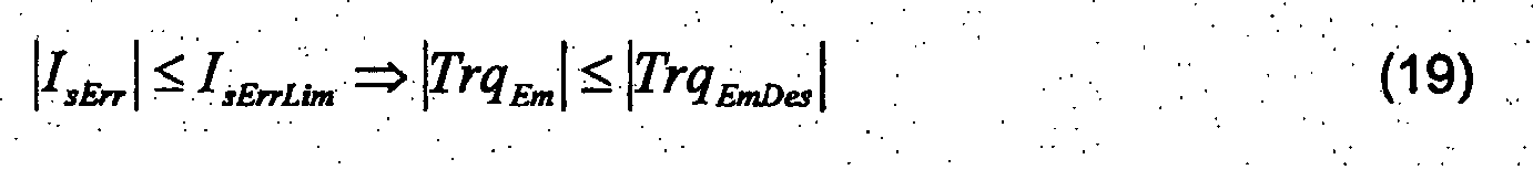

![]()
Außerdem kann auch eine Prüfung des Vorzeichens des wirksamen Drehmomentes TrqEm erfolgen. Dies geschieht wie in Gleichung (21) gezeigt, mit Hilfe des Vorzeichens der elektromagnetischen Leistung PwrEmSens gemäß Gleichung (13) und der Drehzahl n der elektrischen Maschine 1. 
Wenn das auf diese Weise berechnete Vorzeichen nicht mit dem Vorzeichen des Soll-Drehmoments TrqEmDes übereinstimmt, wird ebenfalls ein Fehler detektiert. ![]()
![]()
Wie sich aus den Gleichungen (19) und (29) ergibt, führt der Fall, dass das wirksame TrqEm Drehmoment betragsmäßig kleiner ist als der Betrag des Soll-Drehmoments TrqEmDes über den beschriebenen zusätzlichen Fehlerpfad nicht automatisch zu einer Fehlerdetektion. Dieser weniger kritische Fehlerfall kann aber auch im Grunddrehzahlbereich über die erfindungsgemäße Leistungsbilanz abgefangen werden.As is clear from the equations (19) and (29), the case that the effective Trq Em torque is smaller in magnitude than the amount of the target torque Trq EmDes via the described additional error path does not automatically result in error detection. This less critical error case can also be intercepted in the base speed range via the power balance according to the invention.
Claims (15)
- Method for checking the plausibility of a torque (TrqEmMdl), calculated with the aid of a machine model, of an electric machine (1), the method being characterized in that- a first value (PwrEmMdl) of an electromagnetic power of the electric machine (1) is determined from the calculated torque (TrqEmMdl) and a rotational speed (n) of the electric machine (1),- stator currents (IsU, IsV, IsW) and stator phase voltages (UsU, UsV, UsW) in the phases (U, V, W) of the electric machine (1) are determined,- stator current components (ISA, IsB) are calculated from the stator currents (IsU, IsV, IsW) and the stator phase voltages (UsU, UsV, UsW) with reference to a reference system fixed to the stator,- a second value (PwrEmSens) of the electromagnetic power of the electric machine (1) is determined from the stator current components (ISA, ISB) and the stator phase components (USA, UsB),- the first value (PwrEmMdl) of the electromagnetic power of the electric machine (1) is compared with the second value (PwrEmSens) of the electromagnetic power of the electric machine (1), and- the torque (TrqEmMdl), calculated with the aid of the machine model, of the electric machine (1) is classified as implausible if a deviation of the first value (PwrEmMdl) of the electromagnetic power of the electric machine (1) from the second value (PwrEmSens) of the electromagnetic power of the electric machine (1) exceeds a prescribed power threshold value (PwrErrLim).
- Method according to Claim 1, in which the machine model prescribes a pole pair number (p), a direct-axis current (Isd), a cross current (Isq), an excitation flux (ψExc) as well as a series inductance (Lsd) and a shunt inductance (Lsq) of the electric machine (1), and the torque (TrqEmMdl) of the electric machine (1) is calculated from said parameters.
- Method according to either of Claims 1 and 2, in which the rotational speed (n) of the electric machine (1) is measured.
- Method according to either of Claims 1 and 2, in which the rotational speed (n) is determined from the angular differential between two temporally offset measured current vectors.
- Method according to one of Claims 1 to 4, in which at least one of the stator currents (IsU; IsV; IsW) is measured and all stator currents (IsU; IsV; IsW) not measured are determined by computation.
- Method according to one of Claims 1 to 4, in which all stator currents (IsU, IsV, IsW) are measured and an error in the measuring of the stator currents (IsU, IsV, IsW) is detected if the sum of the stator currents (IsU, IsV, IsW) exceeds a prescribed first stator current threshold value (IsLim).
- Method according to one of the preceding claims, in which the stator phase voltages (UsU, UsV, UsW) are determined by computation, in particular duty ratios (dycU, dycV, dycW) of the individual phases (U, V, W) of the electric machine (1) are determined and an intermediate circuit voltage (UdcLnk) is measured, and the stator phase voltages (UsU, UsV, UsW) are calculated from the duty ratios (dycU, dycV, dycW) and the intermediate circuit voltage (UdcLnk).
- Method according to Claim 6, in which current error voltages (UsUErr, UsVErr, UsWErr) are taken into account in determining the stator phase voltages (UsU, UsV, UsW).
- Method according to Claim 7, in which the current error voltages (UsUErr, UsVErr, UsWErr) are read out from an error voltage characteristic diagram as a function of the stator currents (IsU, IsV, IsW) and the intermediate circuit voltage (UdcLnk).
- Method according to one of the preceding claims, in which a current power loss (PwrElMaLos) of the electric machine (1) is taken into account in determining the second value (PwrEmSens) of the electromagnetic power of the electric machine (1).
- Method according to Claim 10, in which the current power loss (PwrElMaLos) of the electric machine (1) is read out from a power loss characteristic diagram as a function of the absolute value (Is) of the stator current and the rotational speed (n).
- Method according to one of the preceding claims, in which the absolute value of a desired stator current (IsDes) is determined in the basic rotational speed range of the electric machine (1) as a function of an absolute value of a desired torque (TrqEmDes), the absolute value of the desired stator current (IsDes) is compared with the absolute value (Is) of the stator current, and the torque (TrqEmMdl), calculated with the aid of the machine model, of the electric machine (1) is classified as implausible if a deviation in the absolute value of the desired stator current (IsDes) from the absolute value (Is) of the actual stator current exceeds a prescribed second stator current threshold value (IsErrLim).
- Method according to Claim 12, in which the absolute value of the desired stator current (IsDes) is read out from a stator current characteristic diagram as a function of the desired torque (TrqEmDes).
- Method according to either of Claims 12 and 13, in which a sign of an effective torque (TrqEm) is determined as a function of the second value (PwrEmSens) of the electromagnetic power of the electric machine (1) and the rotational speed (n), and the torque (TrqEmMdl) calculated with the aid of the machine model is classified as implausible if the sign of the effective torque (TrqEm) is not equal to the sign of the desired torque (TrqEmDes).
- Machine controller for controlling an electric machine (1), characterized by- means for determining a first value (PwrEmMdl) of an electromagnetic power of the electric machine (1) from a torque (TrqEmMdl), calculated with the aid of a machine model, and a rotational speed (n) of the electric machine (1),- means for calculating stator current components (ISA, IsB) and stator voltage components (USA, UsB) of a reference system, fixed to the stator, from stator currents (IsU, IsV, IsW) and stator phase voltages (UsU, UsV, UsW),- means for determining a second value (PwrEmSens) of the electromagnetic power of the electric machine (1) from the stator current components (ISA, IsB) and the stator phase voltage components (USA, UsB),- means for comparing the first value (PwrEmMdl) of the electromagnetic power of the electric machine (1) with the second value (PwrEmSens) of the electromagnetic power of the electric machine (1), and- means for error detection, in which the torque (TrqEmMdl), calculated with the aid of the machine model, of the electric machine (1) is classified as implausible if a deviation of the first value (PwrEmMdl) of the electromagnetic power of the electric machine (1) from the second value (PwrEmSens) of the electromagnetic power of the electric machine (1) exceeds a prescribed power threshold value (PwrErrLim).
Applications Claiming Priority (2)
| Application Number | Priority Date | Filing Date | Title |
|---|---|---|---|
| DE102009046583A DE102009046583A1 (en) | 2009-11-10 | 2009-11-10 | Method for plausibilizing the torque of an electrical machine and machine controller for controlling an electrical machine and for carrying out the method |
| PCT/EP2010/063607 WO2011057838A1 (en) | 2009-11-10 | 2010-09-16 | Method for checking the plausibility of the torque of an electrical machine and machine controller for controlling an electrical machine and for carrying out the method |
Publications (2)
| Publication Number | Publication Date |
|---|---|
| EP2499737A1 EP2499737A1 (en) | 2012-09-19 |
| EP2499737B1 true EP2499737B1 (en) | 2014-12-10 |
Family
ID=43091771
Family Applications (1)
| Application Number | Title | Priority Date | Filing Date |
|---|---|---|---|
| EP10754508.9A Active EP2499737B1 (en) | 2009-11-10 | 2010-09-16 | Method for checking the plausibility of the torque of an electrical machine and machine controller for controlling an electrical machine and for carrying out the method |
Country Status (7)
| Country | Link |
|---|---|
| US (1) | US9065376B2 (en) |
| EP (1) | EP2499737B1 (en) |
| JP (1) | JP5511973B2 (en) |
| KR (1) | KR101731663B1 (en) |
| CN (1) | CN102598502B (en) |
| DE (1) | DE102009046583A1 (en) |
| WO (1) | WO2011057838A1 (en) |
Families Citing this family (21)
| Publication number | Priority date | Publication date | Assignee | Title |
|---|---|---|---|---|
| EP2540544B1 (en) * | 2011-06-28 | 2014-02-26 | Siemens Aktiengesellschaft | Torque monitoring for vehicles |
| FR2991065B1 (en) * | 2012-05-23 | 2014-05-02 | Schneider Toshiba Inverter | SYSTEM FOR SECURELY CONTROLLING AN ELECTRICAL CHARGE |
| DE102013204191A1 (en) | 2013-03-12 | 2014-09-18 | Robert Bosch Gmbh | Device and method for operating a motor vehicle |
| DE102013215306A1 (en) | 2013-08-02 | 2015-02-05 | Robert Bosch Gmbh | Method for switching on and off an n-phase electric machine in a motor vehicle |
| US9442029B2 (en) * | 2013-12-27 | 2016-09-13 | Deere & Company | Methods of torque estimation and compensation and systems thereof |
| CN104124907B (en) * | 2014-07-29 | 2017-10-20 | 长城汽车股份有限公司 | A kind of current sensor faults processing method and electric machine controller |
| JP6795897B2 (en) * | 2016-03-14 | 2020-12-02 | Ntn株式会社 | Wheel independent drive type vehicle drive control device |
| EP3252943A1 (en) * | 2016-06-02 | 2017-12-06 | Trafag AG | Torque control apparatus, electric drive and method for torque control |
| DE102016112693A1 (en) | 2016-07-11 | 2018-01-11 | Ebm-Papst Mulfingen Gmbh & Co. Kg | Monitoring the operating status of synchronous motors |
| DE202016103713U1 (en) | 2016-07-11 | 2016-08-08 | Ebm-Papst Mulfingen Gmbh & Co. Kg | Monitoring the operating status of synchronous motors |
| EP3348434A1 (en) * | 2017-01-16 | 2018-07-18 | Siemens Aktiengesellschaft | Method for monitoring a drive system, in particular a drive train of an electric vehicle, and control device operating according to this method |
| EP3348435A1 (en) * | 2017-01-16 | 2018-07-18 | Siemens Aktiengesellschaft | Method for monitoring an electric device in a power transmission of an electric vehicle and control unit operating according to this method |
| DE102017208408A1 (en) * | 2017-05-18 | 2018-11-22 | Zf Friedrichshafen Ag | Monitoring a torque of a rotating field machine |
| DE102017116320A1 (en) * | 2017-07-19 | 2019-01-24 | Valeo Siemens Eautomotive Germany Gmbh | Circuit arrangement for an n-phase electric machine, electric machine for a vehicle, vehicle and method for operating an n-phase electric machine |
| DE102017213069A1 (en) * | 2017-07-28 | 2019-01-31 | Robert Bosch Gmbh | Method for determining a rotor position of an electric, rotating machine and an electric, rotating machine for carrying out such a method |
| US11929693B2 (en) * | 2019-12-31 | 2024-03-12 | Mavel edt S.p.A. | Method and system for controlling an electric machine |
| CN113740727B (en) * | 2020-05-13 | 2022-08-12 | 广东威灵电机制造有限公司 | Motor pole pair number detection method and device and motor controller |
| DE102021101813A1 (en) * | 2021-01-27 | 2022-07-28 | Audi Aktiengesellschaft | Method for checking a model temperature of an electrical machine and motor vehicle determined by means of a temperature model |
| US12202356B2 (en) * | 2022-12-01 | 2025-01-21 | GM Global Technology Operations LLC | Motor degradation identification systems and methods using multiple environmental factors |
| DE102022004576A1 (en) | 2022-12-07 | 2024-06-13 | Mercedes-Benz Group AG | Method for calculating and monitoring the torque of a rotating field machine |
| CN116520056B (en) * | 2023-04-28 | 2026-03-13 | 中国第一汽车股份有限公司 | Test methods, apparatus and vehicles for radiated emission function of motor controllers |
Family Cites Families (22)
| Publication number | Priority date | Publication date | Assignee | Title |
|---|---|---|---|---|
| DE3026202A1 (en) * | 1980-07-10 | 1982-02-04 | Siemens AG, 1000 Berlin und 8000 München | TURNFIELD MACHINE DRIVE WITH A CONVERTER-DRIVEN TURNFIELD MACHINE AND A CONVERTER CONTROLLER CONNECTED WITH TWO AC VOLTAGE INTEGRATORS AND A COMPUTER MODEL CIRCUIT |
| DE3034275A1 (en) * | 1980-09-11 | 1982-04-22 | Siemens AG, 1000 Berlin und 8000 München | DEVICE FOR DETERMINING THE PARAMETER VALUES FOR STANDAL RESISTANCE, MAIN INDUCTIVITY AND SPREADING INDUCTIVITY OF AN ASYNCHRONOUS MACHINE |
| DE3262852D1 (en) * | 1981-05-25 | 1985-05-09 | Siemens Ag | Apparatus for controlling a salient pole machine and asimulator circuit for such a machine |
| JPS6231385A (en) * | 1985-07-31 | 1987-02-10 | Yaskawa Electric Mfg Co Ltd | Field pole position correction method for synchronous motor |
| JP2000177610A (en) | 1998-12-15 | 2000-06-27 | Toyoda Mach Works Ltd | Motor control device |
| JP2003500718A (en) * | 1999-05-19 | 2003-01-07 | ローベルト ボッシュ ゲゼルシャフト ミット ベシュレンクテル ハフツング | Control system with model-assisted safety monitoring of electronically controlled operating elements in a vehicle |
| DE10019152A1 (en) * | 1999-05-19 | 2000-12-21 | Bosch Gmbh Robert | Control system with model-based safety monitoring of an electronically controlled actuator in a motor vehicle |
| US6646394B2 (en) * | 2001-07-09 | 2003-11-11 | Nissan Motor Co., Ltd. | Control device for plurality of rotating electrical machines |
| JP3783941B2 (en) | 2002-04-25 | 2006-06-07 | 株式会社ジェイテクト | Motor control device |
| GB2404100A (en) * | 2003-07-17 | 2005-01-19 | Bombardier Transp | Model-based monitoring an operation of a converter |
| ITMO20040218A1 (en) * | 2004-08-31 | 2004-11-30 | C A R E R Carrellificio Elettronico | METHOD FOR THE CONTROL OF A SYNCHRONOUS ROTATING MOTOR WINDED. |
| DE102005040783A1 (en) | 2005-08-29 | 2007-03-08 | Robert Bosch Gmbh | Method for controlling a vehicle drive unit |
| JP4804100B2 (en) | 2005-10-18 | 2011-10-26 | 三洋電機株式会社 | Motor drive device, control method therefor, and air conditioner |
| DE102006005854A1 (en) * | 2006-02-09 | 2007-08-23 | Robert Bosch Gmbh | Method and device for determining the torque of an electrical machine |
| JP5024827B2 (en) * | 2006-09-27 | 2012-09-12 | 東芝キヤリア株式会社 | Inverter device |
| JP5125216B2 (en) * | 2007-05-15 | 2013-01-23 | 日本精工株式会社 | Electric power steering device |
| JP5196923B2 (en) | 2007-09-07 | 2013-05-15 | 株式会社東芝 | Laundry equipment |
| EP2040427A1 (en) * | 2007-09-22 | 2009-03-25 | New Day Investment Limited | High speed electrical data transmission system |
| DE102008008536A1 (en) * | 2008-02-11 | 2009-08-13 | Robert Bosch Gmbh | Method for controlling an electric machine and control device |
| JP2009207315A (en) * | 2008-02-28 | 2009-09-10 | Hitachi Ltd | Motor controller |
| JP4458174B2 (en) * | 2008-03-21 | 2010-04-28 | 株式会社デンソー | Rotating machine control device and rotating machine control system |
| ATE556906T1 (en) * | 2009-12-24 | 2012-05-15 | Kanzaki Kokyukoki Mfg Co Ltd | ELECTRIC VEHICLE |
-
2009
- 2009-11-10 DE DE102009046583A patent/DE102009046583A1/en not_active Withdrawn
-
2010
- 2010-09-16 WO PCT/EP2010/063607 patent/WO2011057838A1/en not_active Ceased
- 2010-09-16 KR KR1020127011947A patent/KR101731663B1/en active Active
- 2010-09-16 CN CN201080050645.6A patent/CN102598502B/en active Active
- 2010-09-16 US US13/505,591 patent/US9065376B2/en active Active
- 2010-09-16 EP EP10754508.9A patent/EP2499737B1/en active Active
- 2010-09-16 JP JP2012538251A patent/JP5511973B2/en active Active
Also Published As
| Publication number | Publication date |
|---|---|
| US20120278007A1 (en) | 2012-11-01 |
| KR101731663B1 (en) | 2017-04-28 |
| KR20120091194A (en) | 2012-08-17 |
| WO2011057838A1 (en) | 2011-05-19 |
| DE102009046583A1 (en) | 2011-05-12 |
| JP2013510555A (en) | 2013-03-21 |
| EP2499737A1 (en) | 2012-09-19 |
| JP5511973B2 (en) | 2014-06-04 |
| CN102598502A (en) | 2012-07-18 |
| US9065376B2 (en) | 2015-06-23 |
| CN102598502B (en) | 2015-02-04 |
Similar Documents
| Publication | Publication Date | Title |
|---|---|---|
| EP2499737B1 (en) | Method for checking the plausibility of the torque of an electrical machine and machine controller for controlling an electrical machine and for carrying out the method | |
| DE102010042330B4 (en) | Methods and systems for performing fault diagnosis for rotors of electric motors | |
| DE60036192T2 (en) | Synchronous motor control device and vehicle with the control device | |
| EP1479157B1 (en) | Method for the detection of abnormalities of electric motors | |
| EP3017538B1 (en) | Method for controlling a multiphase frequency converter of driving an electric machine and corresponding controller | |
| EP2671090B1 (en) | Method and device for detecting a malfunction of an electric machine | |
| DE102012212247A1 (en) | Method, systems and apparatus for controlling a polyphase inverter | |
| DE102009023372A1 (en) | Electronic control device for vehicles and steering control system | |
| EP3815237B1 (en) | Method and device for determining the position and the rotational speed of a rotor of an electrical machine | |
| EP0690556B1 (en) | Stop recognizing of inverter controlled motor without speed sensor by restarting | |
| DE112018007527T5 (en) | Electric motor control device | |
| DE102014106716B4 (en) | Rotary electric machine control device having an abnormality detection function | |
| DE102016224178A1 (en) | Control of a six-phase PSM | |
| EP2998753B1 (en) | Monitoring device for an electric machine, control device and method | |
| DE102019202464A1 (en) | Method and control device for determining at least one characteristic value of a drive train, which is located in the installed state in an electrically drivable motor vehicle, and motor vehicle | |
| DE102007021892A1 (en) | Method and device for controlling an electric motor using star voltage modulation | |
| EP2540544B1 (en) | Torque monitoring for vehicles | |
| EP2777144B1 (en) | Method for calibrating a multiphase inverter, operating apparatus, computer program, and computer program product | |
| DE10100565B4 (en) | A method of determining a torque applied by an asynchronous electric motor | |
| DE112019001069T5 (en) | Motor control device and electric vehicle | |
| WO2017190898A1 (en) | Method for determining the phase currents of an electric machine having a converter | |
| EP3476038B1 (en) | Method for controlling a synchronous machine and control device for a synchronous machine | |
| EP3657670B1 (en) | Method and device for fail-safe speed monitoring | |
| DE102012208747A1 (en) | Method for operating permanent-magnet synchronous machine for e.g. electric drive of automobile, involves providing pulse width modulation default values for phases of machine upon detection of short circuit at power switches of phases | |
| EP3406027B1 (en) | Device and method for controlling an electric machine |
Legal Events
| Date | Code | Title | Description |
|---|---|---|---|
| PUAI | Public reference made under article 153(3) epc to a published international application that has entered the european phase |
Free format text: ORIGINAL CODE: 0009012 |
|
| 17P | Request for examination filed |
Effective date: 20120611 |
|
| AK | Designated contracting states |
Kind code of ref document: A1 Designated state(s): AL AT BE BG CH CY CZ DE DK EE ES FI FR GB GR HR HU IE IS IT LI LT LU LV MC MK MT NL NO PL PT RO SE SI SK SM TR |
|
| DAX | Request for extension of the european patent (deleted) | ||
| REG | Reference to a national code |
Ref country code: DE Ref legal event code: R079 Ref document number: 502010008460 Country of ref document: DE Free format text: PREVIOUS MAIN CLASS: H02P0029020000 Ipc: H02P0021140000 |
|
| GRAP | Despatch of communication of intention to grant a patent |
Free format text: ORIGINAL CODE: EPIDOSNIGR1 |
|
| RIC1 | Information provided on ipc code assigned before grant |
Ipc: H02P 29/02 20060101ALI20140826BHEP Ipc: H02P 21/14 20060101AFI20140826BHEP |
|
| INTG | Intention to grant announced |
Effective date: 20140912 |
|
| GRAS | Grant fee paid |
Free format text: ORIGINAL CODE: EPIDOSNIGR3 |
|
| GRAA | (expected) grant |
Free format text: ORIGINAL CODE: 0009210 |
|
| AK | Designated contracting states |
Kind code of ref document: B1 Designated state(s): AL AT BE BG CH CY CZ DE DK EE ES FI FR GB GR HR HU IE IS IT LI LT LU LV MC MK MT NL NO PL PT RO SE SI SK SM TR |
|
| REG | Reference to a national code |
Ref country code: GB Ref legal event code: FG4D Free format text: NOT ENGLISH |
|
| REG | Reference to a national code |
Ref country code: CH Ref legal event code: EP |
|
| REG | Reference to a national code |
Ref country code: IE Ref legal event code: FG4D Free format text: LANGUAGE OF EP DOCUMENT: GERMAN |
|
| REG | Reference to a national code |
Ref country code: AT Ref legal event code: REF Ref document number: 701094 Country of ref document: AT Kind code of ref document: T Effective date: 20150115 |
|
| REG | Reference to a national code |
Ref country code: DE Ref legal event code: R096 Ref document number: 502010008460 Country of ref document: DE Effective date: 20150122 |
|
| REG | Reference to a national code |
Ref country code: NL Ref legal event code: VDEP Effective date: 20141210 |
|
| REG | Reference to a national code |
Ref country code: NL Ref legal event code: VDEP Effective date: 20141210 |
|
| PG25 | Lapsed in a contracting state [announced via postgrant information from national office to epo] |
Ref country code: ES Free format text: LAPSE BECAUSE OF FAILURE TO SUBMIT A TRANSLATION OF THE DESCRIPTION OR TO PAY THE FEE WITHIN THE PRESCRIBED TIME-LIMIT Effective date: 20141210 Ref country code: FI Free format text: LAPSE BECAUSE OF FAILURE TO SUBMIT A TRANSLATION OF THE DESCRIPTION OR TO PAY THE FEE WITHIN THE PRESCRIBED TIME-LIMIT Effective date: 20141210 Ref country code: LT Free format text: LAPSE BECAUSE OF FAILURE TO SUBMIT A TRANSLATION OF THE DESCRIPTION OR TO PAY THE FEE WITHIN THE PRESCRIBED TIME-LIMIT Effective date: 20141210 Ref country code: NO Free format text: LAPSE BECAUSE OF FAILURE TO SUBMIT A TRANSLATION OF THE DESCRIPTION OR TO PAY THE FEE WITHIN THE PRESCRIBED TIME-LIMIT Effective date: 20150310 |
|
| REG | Reference to a national code |
Ref country code: LT Ref legal event code: MG4D |
|
| PG25 | Lapsed in a contracting state [announced via postgrant information from national office to epo] |
Ref country code: LV Free format text: LAPSE BECAUSE OF FAILURE TO SUBMIT A TRANSLATION OF THE DESCRIPTION OR TO PAY THE FEE WITHIN THE PRESCRIBED TIME-LIMIT Effective date: 20141210 Ref country code: HR Free format text: LAPSE BECAUSE OF FAILURE TO SUBMIT A TRANSLATION OF THE DESCRIPTION OR TO PAY THE FEE WITHIN THE PRESCRIBED TIME-LIMIT Effective date: 20141210 Ref country code: GR Free format text: LAPSE BECAUSE OF FAILURE TO SUBMIT A TRANSLATION OF THE DESCRIPTION OR TO PAY THE FEE WITHIN THE PRESCRIBED TIME-LIMIT Effective date: 20150311 Ref country code: SE Free format text: LAPSE BECAUSE OF FAILURE TO SUBMIT A TRANSLATION OF THE DESCRIPTION OR TO PAY THE FEE WITHIN THE PRESCRIBED TIME-LIMIT Effective date: 20141210 |
|
| PG25 | Lapsed in a contracting state [announced via postgrant information from national office to epo] |
Ref country code: NL Free format text: LAPSE BECAUSE OF FAILURE TO SUBMIT A TRANSLATION OF THE DESCRIPTION OR TO PAY THE FEE WITHIN THE PRESCRIBED TIME-LIMIT Effective date: 20141210 |
|
| PG25 | Lapsed in a contracting state [announced via postgrant information from national office to epo] |
Ref country code: EE Free format text: LAPSE BECAUSE OF FAILURE TO SUBMIT A TRANSLATION OF THE DESCRIPTION OR TO PAY THE FEE WITHIN THE PRESCRIBED TIME-LIMIT Effective date: 20141210 Ref country code: SK Free format text: LAPSE BECAUSE OF FAILURE TO SUBMIT A TRANSLATION OF THE DESCRIPTION OR TO PAY THE FEE WITHIN THE PRESCRIBED TIME-LIMIT Effective date: 20141210 Ref country code: RO Free format text: LAPSE BECAUSE OF FAILURE TO SUBMIT A TRANSLATION OF THE DESCRIPTION OR TO PAY THE FEE WITHIN THE PRESCRIBED TIME-LIMIT Effective date: 20141210 Ref country code: PT Free format text: LAPSE BECAUSE OF FAILURE TO SUBMIT A TRANSLATION OF THE DESCRIPTION OR TO PAY THE FEE WITHIN THE PRESCRIBED TIME-LIMIT Effective date: 20150410 Ref country code: CZ Free format text: LAPSE BECAUSE OF FAILURE TO SUBMIT A TRANSLATION OF THE DESCRIPTION OR TO PAY THE FEE WITHIN THE PRESCRIBED TIME-LIMIT Effective date: 20141210 |
|
| PG25 | Lapsed in a contracting state [announced via postgrant information from national office to epo] |
Ref country code: PL Free format text: LAPSE BECAUSE OF FAILURE TO SUBMIT A TRANSLATION OF THE DESCRIPTION OR TO PAY THE FEE WITHIN THE PRESCRIBED TIME-LIMIT Effective date: 20141210 Ref country code: IS Free format text: LAPSE BECAUSE OF FAILURE TO SUBMIT A TRANSLATION OF THE DESCRIPTION OR TO PAY THE FEE WITHIN THE PRESCRIBED TIME-LIMIT Effective date: 20150410 |
|
| REG | Reference to a national code |
Ref country code: DE Ref legal event code: R097 Ref document number: 502010008460 Country of ref document: DE |
|
| PLBE | No opposition filed within time limit |
Free format text: ORIGINAL CODE: 0009261 |
|
| STAA | Information on the status of an ep patent application or granted ep patent |
Free format text: STATUS: NO OPPOSITION FILED WITHIN TIME LIMIT |
|
| PG25 | Lapsed in a contracting state [announced via postgrant information from national office to epo] |
Ref country code: DK Free format text: LAPSE BECAUSE OF FAILURE TO SUBMIT A TRANSLATION OF THE DESCRIPTION OR TO PAY THE FEE WITHIN THE PRESCRIBED TIME-LIMIT Effective date: 20141210 |
|
| 26N | No opposition filed |
Effective date: 20150911 |
|
| PG25 | Lapsed in a contracting state [announced via postgrant information from national office to epo] |
Ref country code: SI Free format text: LAPSE BECAUSE OF FAILURE TO SUBMIT A TRANSLATION OF THE DESCRIPTION OR TO PAY THE FEE WITHIN THE PRESCRIBED TIME-LIMIT Effective date: 20141210 |
|
| PG25 | Lapsed in a contracting state [announced via postgrant information from national office to epo] |
Ref country code: MC Free format text: LAPSE BECAUSE OF FAILURE TO SUBMIT A TRANSLATION OF THE DESCRIPTION OR TO PAY THE FEE WITHIN THE PRESCRIBED TIME-LIMIT Effective date: 20141210 Ref country code: LU Free format text: LAPSE BECAUSE OF FAILURE TO SUBMIT A TRANSLATION OF THE DESCRIPTION OR TO PAY THE FEE WITHIN THE PRESCRIBED TIME-LIMIT Effective date: 20150916 |
|
| REG | Reference to a national code |
Ref country code: CH Ref legal event code: PL |
|
| REG | Reference to a national code |
Ref country code: IE Ref legal event code: MM4A |
|
| PG25 | Lapsed in a contracting state [announced via postgrant information from national office to epo] |
Ref country code: IE Free format text: LAPSE BECAUSE OF NON-PAYMENT OF DUE FEES Effective date: 20150916 Ref country code: CH Free format text: LAPSE BECAUSE OF NON-PAYMENT OF DUE FEES Effective date: 20150930 Ref country code: LI Free format text: LAPSE BECAUSE OF NON-PAYMENT OF DUE FEES Effective date: 20150930 |
|
| REG | Reference to a national code |
Ref country code: FR Ref legal event code: PLFP Year of fee payment: 7 |
|
| REG | Reference to a national code |
Ref country code: AT Ref legal event code: MM01 Ref document number: 701094 Country of ref document: AT Kind code of ref document: T Effective date: 20150916 |
|
| PG25 | Lapsed in a contracting state [announced via postgrant information from national office to epo] |
Ref country code: AT Free format text: LAPSE BECAUSE OF NON-PAYMENT OF DUE FEES Effective date: 20150916 |
|
| PG25 | Lapsed in a contracting state [announced via postgrant information from national office to epo] |
Ref country code: MT Free format text: LAPSE BECAUSE OF FAILURE TO SUBMIT A TRANSLATION OF THE DESCRIPTION OR TO PAY THE FEE WITHIN THE PRESCRIBED TIME-LIMIT Effective date: 20141210 |
|
| PG25 | Lapsed in a contracting state [announced via postgrant information from national office to epo] |
Ref country code: SM Free format text: LAPSE BECAUSE OF FAILURE TO SUBMIT A TRANSLATION OF THE DESCRIPTION OR TO PAY THE FEE WITHIN THE PRESCRIBED TIME-LIMIT Effective date: 20141210 Ref country code: HU Free format text: LAPSE BECAUSE OF FAILURE TO SUBMIT A TRANSLATION OF THE DESCRIPTION OR TO PAY THE FEE WITHIN THE PRESCRIBED TIME-LIMIT; INVALID AB INITIO Effective date: 20100916 Ref country code: BG Free format text: LAPSE BECAUSE OF FAILURE TO SUBMIT A TRANSLATION OF THE DESCRIPTION OR TO PAY THE FEE WITHIN THE PRESCRIBED TIME-LIMIT Effective date: 20141210 |
|
| PG25 | Lapsed in a contracting state [announced via postgrant information from national office to epo] |
Ref country code: CY Free format text: LAPSE BECAUSE OF FAILURE TO SUBMIT A TRANSLATION OF THE DESCRIPTION OR TO PAY THE FEE WITHIN THE PRESCRIBED TIME-LIMIT Effective date: 20141210 |
|
| PG25 | Lapsed in a contracting state [announced via postgrant information from national office to epo] |
Ref country code: BE Free format text: LAPSE BECAUSE OF NON-PAYMENT OF DUE FEES Effective date: 20150930 |
|
| PG25 | Lapsed in a contracting state [announced via postgrant information from national office to epo] |
Ref country code: TR Free format text: LAPSE BECAUSE OF FAILURE TO SUBMIT A TRANSLATION OF THE DESCRIPTION OR TO PAY THE FEE WITHIN THE PRESCRIBED TIME-LIMIT Effective date: 20141210 |
|
| REG | Reference to a national code |
Ref country code: FR Ref legal event code: PLFP Year of fee payment: 8 |
|
| PG25 | Lapsed in a contracting state [announced via postgrant information from national office to epo] |
Ref country code: MK Free format text: LAPSE BECAUSE OF FAILURE TO SUBMIT A TRANSLATION OF THE DESCRIPTION OR TO PAY THE FEE WITHIN THE PRESCRIBED TIME-LIMIT Effective date: 20141210 |
|
| REG | Reference to a national code |
Ref country code: FR Ref legal event code: PLFP Year of fee payment: 9 |
|
| PG25 | Lapsed in a contracting state [announced via postgrant information from national office to epo] |
Ref country code: AL Free format text: LAPSE BECAUSE OF FAILURE TO SUBMIT A TRANSLATION OF THE DESCRIPTION OR TO PAY THE FEE WITHIN THE PRESCRIBED TIME-LIMIT Effective date: 20141210 |
|
| PGFP | Annual fee paid to national office [announced via postgrant information from national office to epo] |
Ref country code: GB Payment date: 20220927 Year of fee payment: 13 |
|
| PGFP | Annual fee paid to national office [announced via postgrant information from national office to epo] |
Ref country code: IT Payment date: 20220930 Year of fee payment: 13 |
|
| P01 | Opt-out of the competence of the unified patent court (upc) registered |
Effective date: 20230509 |
|
| GBPC | Gb: european patent ceased through non-payment of renewal fee |
Effective date: 20230916 |
|
| PG25 | Lapsed in a contracting state [announced via postgrant information from national office to epo] |
Ref country code: GB Free format text: LAPSE BECAUSE OF NON-PAYMENT OF DUE FEES Effective date: 20230916 |
|
| PG25 | Lapsed in a contracting state [announced via postgrant information from national office to epo] |
Ref country code: GB Free format text: LAPSE BECAUSE OF NON-PAYMENT OF DUE FEES Effective date: 20230916 |
|
| PG25 | Lapsed in a contracting state [announced via postgrant information from national office to epo] |
Ref country code: IT Free format text: LAPSE BECAUSE OF NON-PAYMENT OF DUE FEES Effective date: 20230916 |
|
| PG25 | Lapsed in a contracting state [announced via postgrant information from national office to epo] |
Ref country code: IT Free format text: LAPSE BECAUSE OF NON-PAYMENT OF DUE FEES Effective date: 20230916 |
|
| PGFP | Annual fee paid to national office [announced via postgrant information from national office to epo] |
Ref country code: FR Payment date: 20250926 Year of fee payment: 16 |
|
| PGFP | Annual fee paid to national office [announced via postgrant information from national office to epo] |
Ref country code: DE Payment date: 20251121 Year of fee payment: 16 |