EP2436280B1 - Mechanical-magnetic connection structure - Google Patents
Mechanical-magnetic connection structure Download PDFInfo
- Publication number
- EP2436280B1 EP2436280B1 EP11175558.3A EP11175558A EP2436280B1 EP 2436280 B1 EP2436280 B1 EP 2436280B1 EP 11175558 A EP11175558 A EP 11175558A EP 2436280 B1 EP2436280 B1 EP 2436280B1
- Authority
- EP
- European Patent Office
- Prior art keywords
- magnet
- armature
- locking piece
- spring
- locking
- Prior art date
- Legal status (The legal status is an assumption and is not a legal conclusion. Google has not performed a legal analysis and makes no representation as to the accuracy of the status listed.)
- Active
Links
Images

















Classifications
-
- A—HUMAN NECESSITIES
- A45—HAND OR TRAVELLING ARTICLES
- A45C—PURSES; LUGGAGE; HAND CARRIED BAGS
- A45C13/00—Details; Accessories
- A45C13/10—Arrangement of fasteners
- A45C13/1069—Arrangement of fasteners magnetic
-
- A—HUMAN NECESSITIES
- A45—HAND OR TRAVELLING ARTICLES
- A45C—PURSES; LUGGAGE; HAND CARRIED BAGS
- A45C13/00—Details; Accessories
- A45C13/10—Arrangement of fasteners
-
- A—HUMAN NECESSITIES
- A41—WEARING APPAREL
- A41F—GARMENT FASTENINGS; SUSPENDERS
- A41F1/00—Fastening devices specially adapted for garments
-
- A—HUMAN NECESSITIES
- A44—HABERDASHERY; JEWELLERY
- A44B—BUTTONS, PINS, BUCKLES, SLIDE FASTENERS, OR THE LIKE
- A44B11/00—Buckles; Similar fasteners for interconnecting straps or the like, e.g. for safety belts
- A44B11/25—Buckles; Similar fasteners for interconnecting straps or the like, e.g. for safety belts with two or more separable parts
-
- A—HUMAN NECESSITIES
- A44—HABERDASHERY; JEWELLERY
- A44B—BUTTONS, PINS, BUCKLES, SLIDE FASTENERS, OR THE LIKE
- A44B11/00—Buckles; Similar fasteners for interconnecting straps or the like, e.g. for safety belts
- A44B11/25—Buckles; Similar fasteners for interconnecting straps or the like, e.g. for safety belts with two or more separable parts
- A44B11/258—Buckles; Similar fasteners for interconnecting straps or the like, e.g. for safety belts with two or more separable parts fastening by superposing one part on top of the other
-
- A—HUMAN NECESSITIES
- A44—HABERDASHERY; JEWELLERY
- A44B—BUTTONS, PINS, BUCKLES, SLIDE FASTENERS, OR THE LIKE
- A44B11/00—Buckles; Similar fasteners for interconnecting straps or the like, e.g. for safety belts
- A44B11/25—Buckles; Similar fasteners for interconnecting straps or the like, e.g. for safety belts with two or more separable parts
- A44B11/2592—Buckles; Similar fasteners for interconnecting straps or the like, e.g. for safety belts with two or more separable parts fastening by sliding in the main plane or a plane parallel to the main plane of the buckle
-
- A—HUMAN NECESSITIES
- A44—HABERDASHERY; JEWELLERY
- A44B—BUTTONS, PINS, BUCKLES, SLIDE FASTENERS, OR THE LIKE
- A44B17/00—Press-button or snap fasteners
- A44B17/0011—Press-button fasteners in which the elastic retaining action is obtained by a spring working in the plane of the fastener
-
- A—HUMAN NECESSITIES
- A44—HABERDASHERY; JEWELLERY
- A44B—BUTTONS, PINS, BUCKLES, SLIDE FASTENERS, OR THE LIKE
- A44B99/00—Subject matter not provided for in other groups of this subclass
-
- A—HUMAN NECESSITIES
- A44—HABERDASHERY; JEWELLERY
- A44D—INDEXING SCHEME RELATING TO BUTTONS, PINS, BUCKLES OR SLIDE FASTENERS, AND TO JEWELLERY, BRACELETS OR OTHER PERSONAL ADORNMENTS
- A44D2203/00—Fastening by use of magnets
-
- A—HUMAN NECESSITIES
- A45—HAND OR TRAVELLING ARTICLES
- A45F—TRAVELLING OR CAMP EQUIPMENT: SACKS OR PACKS CARRIED ON THE BODY
- A45F3/00—Travelling or camp articles; Sacks or packs carried on the body
- A45F2003/001—Accessories
-
- E—FIXED CONSTRUCTIONS
- E05—LOCKS; KEYS; WINDOW OR DOOR FITTINGS; SAFES
- E05B—LOCKS; ACCESSORIES THEREFOR; HANDCUFFS
- E05B15/00—Other details of locks; Parts for engagement by bolts of fastening devices
- E05B15/0053—Other details of locks; Parts for engagement by bolts of fastening devices means providing a stable, i.e. indexed, position of lock parts
- E05B15/0073—Other details of locks; Parts for engagement by bolts of fastening devices means providing a stable, i.e. indexed, position of lock parts magnetically operated
-
- E—FIXED CONSTRUCTIONS
- E05—LOCKS; KEYS; WINDOW OR DOOR FITTINGS; SAFES
- E05C—BOLTS OR FASTENING DEVICES FOR WINGS, SPECIALLY FOR DOORS OR WINDOWS
- E05C19/00—Other devices specially designed for securing wings, e.g. with suction cups
- E05C19/16—Devices holding the wing by magnetic or electromagnetic attraction
-
- H—ELECTRICITY
- H01—ELECTRIC ELEMENTS
- H01F—MAGNETS; INDUCTANCES; TRANSFORMERS; SELECTION OF MATERIALS FOR THEIR MAGNETIC PROPERTIES
- H01F7/00—Magnets
- H01F7/02—Permanent magnets [PM]
- H01F7/0231—Magnetic circuits with PM for power or force generation
- H01F7/0252—PM holding devices
- H01F7/0263—Closures, bags, bands, engagement devices with male and female parts
-
- Y—GENERAL TAGGING OF NEW TECHNOLOGICAL DEVELOPMENTS; GENERAL TAGGING OF CROSS-SECTIONAL TECHNOLOGIES SPANNING OVER SEVERAL SECTIONS OF THE IPC; TECHNICAL SUBJECTS COVERED BY FORMER USPC CROSS-REFERENCE ART COLLECTIONS [XRACs] AND DIGESTS
- Y10—TECHNICAL SUBJECTS COVERED BY FORMER USPC
- Y10T—TECHNICAL SUBJECTS COVERED BY FORMER US CLASSIFICATION
- Y10T292/00—Closure fasteners
- Y10T292/11—Magnetic
Definitions
- the invention relates to a mechanical-magnetic connection construction, ie a mechanical lock with magnetic force support, which is particularly suitable for closures, as used on bags, backpacks and similar items, this list is not intended to limit the scope of the invention.
- the document US20070133156 discloses a mechanical-magnetic connection construction according to the preamble of claim 1. Basically, such connection structures can be divided into two main groups. There are mechanical connecting structures, the opening and closing mechanism consists of a combination of mostly positive and non-positively acting components. Frequently, springs are used to maintain a locked state so that closing and opening must occur against the spring force.
- Such connection constructions are known in the art, so that reference is made only to the prior art from the contents of subclasses IPC A44B.
- connection constructions are the magnetically-acting connection structures in which the magnetic force is used to hold the connection together. These connection constructions are also well known for closures of bags and other containers of the art, so that also here only the contents of the subclasses of IPC E05C is referenced.
- a positive mechanical lock usually has a mechanical component that is loaded when the lock is loaded to train, pressure or shearing.
- the size of the mechanical resistance of this component defines the stability of the connection structure.
- Mechanical connection structures are inexpensive to produce because z. B. in pocket closures only very inexpensive iron parts or plastic parts are used.
- connection constructions have in principle the property that when mating manually a locking spring force must be overcome. Therefore, in some cases, the handling of the connection constructions is not very comfortable, so that use is made of magnetic connection constructions, because these mutually pull themselves together due to the magnetic force.
- haptic The force felt when closing and opening on the hand. Especially with closures that are operated by hand, the feel of the human hand force must be adjusted.
- the magnet and the associated anchor must be dimensioned according to the holding force. If no special requirements are placed on the locking force and the haptics, these connections are practical.
- closures must be oversized in certain cases, however, if z. B. safety requirements are met. This can z. B. be required in a backpack for mountaineers. This backpack is also allowed not open when the shutter is loaded with a multiple of the normal holding force, which z. B. may occur in a crash.
- closures are designed with such a requirement profile as mechanical closures, since with mechanical structures and high safety factors can be realized without much additional effort. In this respect, these connection constructions have prevailed on the mass market.
- connection construction has two connection modules and serves to connect two elements, to each of which one of the connection modules can be fastened.
- the locking piece and the locking element are formed so that the mechanical strength is sufficient depending on the actual occurring or possible loads.
- the locking piece has a recess, hereinafter referred to as a gap. If the locking piece is displaced relative to the spring locking element so that the hook head and the gap are in opposition, no positive connection is no longer given, because the gap is dimensioned so that the hook head in the gap does not find support. It is clear to those skilled in the art that also the end of the locking piece has the effect of the gap described above, i. H. if no more locking piece is present, the example mentioned hook head can no longer find a hold. Furthermore, it is clear to those skilled in the art that this shift can also be rotational or tilting.
- connection construction furthermore has a magnet armature construction, wherein the magnet is arranged in one of the connection modules and the armature is arranged in the other connection module.
- the magnetic force between armature and magnet is chosen so large that during the closing operation, the connection modules are pulled from a predetermined minimum distance from each other, whereby the spring locking element urges against the locking piece until it snaps into engagement.
- magnet and armature are dimensioned so that the spring force of the spring locking element is overcome. It will be clear to those skilled in the art that magnet-armature constructions can not consist of only a single magnet and a single armature.
- the armature consists of a ferromagnetic material or may be a magnet.
- Certain magnetic anchor designs not only attract, but can also repel when opposing two magnetic poles of the same name. Unless special additional conditions apply, it does not matter if the magnet is moved relative to the armature or the armature is opposite to the magnet. It is also clear that the interaction between magnet and armature is the same as between two magnet attracting.
- connection modules When the connection modules are connected, there is a mechanical lock and also a magnetic attraction. It should be noted, however, that magnetic attraction absorbs only a negligible part of the main load of the connection.
- the magnetic anchor construction almost exclusively serves to automatically close the connection.
- connection module 1 with the magnet and connection module 2 with the armature laterally shifted so far until the magnetic force is sufficiently weakened to easily separate the modules by hand. This is the case when the armature surface facing the magnet has become sufficiently small. It is clear that the displacement between the magnet and the armature can also be a twist or a pivoting.
- the movable magnet is coupled to the locking piece, i. H. with the magnet and the locking piece is moved, wherein the term “coupled” not only means that the locking piece must be rigidly connected to the magnet.
- a coupling also means a connection via a spring.
- a coupling is also present when a driver moves the locking piece, but this driver is not always applied to the locking piece, d. H. if a game exists.
- connection structure has a particularly soft opening feel, because to open only the magnetic force must be weakened by the lateral displacement of the magnet and armature or canceled altogether.
- connection construction in the composite state is as stable as a mechanical connection construction.
- the skilled worker is aware of how mechanical components can be brought from a position to a second position. All that needs to do is to apply a force to the component.
- a return spring is used, which is biased when opening the connecting structure. It will be clear to those skilled in the art that this return spring need only be so strong as to urge the functional elements moved during opening back into their starting position. For this purpose, only a very small force is required, so that only a weak return spring is required, so that the aforementioned soft and pleasant feel is maintained.
- the magnet-armature construction on a plurality of locking elements or a locking element with a plurality of locking portions With this embodiment of the invention, it is z. B. possible to better distribute the attacking force.
- the magnet-armature construction on a coupling device which has a game in the direction of movement of the movable magnet, so that the locking piece is pulled by means of a stopper only in the direction of the magnet when the game is used up is.
- the advantage of this embodiment is that the displacement of the magnet from the armature can be greater than the distance that the locking piece must be moved until the gap is in opposition to the spring locking element.
- connecting structure can be constructed in which the displacement of the magnet from the armature due to structural constraints must be greater than the path that the locking piece is moved.
- the magnetic anchor construction as a coupling device on a coupling spring whose spring force extends along the direction of movement of the magnet and the locking piece.
- the advantage of this embodiment is that with this combination of features a security against the opening of the connecting structure has been created under stress.
- the spring is dimensioned so that in the unloaded state of the mechanical locking device when moving the magnet via the coupling device and the locking piece is pulled along. In the loaded state, the frictional force between the spring locking element and the locking piece is greater than the spring force, ie, the magnet can, for. B. be moved by hand without the mechanical lock opens. If the mechanical lock is relieved in this state, the spring pulls or pushes the locking piece in the opening direction, so that the connection can be opened immediately.
- the magnetic anchor construction on a coupling device which has a game in the direction of movement of the movable magnet, so that the locking piece is pulled by means of a stop only in the direction of the magnet when the game is used up is. Furthermore, a remindstellkarfeder is provided for the locking piece whose spring force extends along the direction of movement of the locking piece. When the magnet is displaced from the armature and the play of the coupling device is used up, the return spring is stretched. When the connection is released, magnet and armature pull in opposition and at the same time the locking piece is pulled to its original position.
- the magnet-armature construction on a coupling device which has a game in the direction of movement of the movable magnet, so that the locking piece is pulled by means of a stop only in the direction of the magnet when the game is used up is. Furthermore, a return spring for the locking piece is provided, whose spring force extends along the direction of movement of the locking piece. When the magnet is displaced from the armature and the play of the coupling device is used up, the return spring is compressed. When the connection is released, magnet and armature pull in opposition and at the same time the locking piece is pushed into its original position.
- an operable by hand or by foot actuating device for moving the magnet or the armature is provided which is movably mounted in one of the two connection modules.
- a tangible object is provided on one of the connection modules, which can be placed by hand on the other connection module.
- This embodiment of the invention is suitable for. B. for connecting a bicycle lamp with the bicycle handlebar.
- the anchor is directly connected to the object in one piece.
- the magnet-armature construction in a connection module at least one magnet and in the other connection module at least one ferromagnetic armature or poled on attraction magnet. This arrangement is preferred when a low cost connection is needed.
- This arrangement is preferred when a robust connection is needed because this magnetic anchor design is done no mechanical contact of the magnetic surface with the surface of the armature, so that damage to the sensitive magnetic surface is avoided, for example, during repeated displacement, even if foreign objects such. B. sand in between.
- the magnet-armature construction in a connection module on a magnet with a ferromagnetic baffle and in the other connection module on a ferromagnetic armature, wherein the magnet and the baffles are arranged so that they are in magnetic operative relationship with the ferromagnetic anchor stand.
- This arrangement is preferred if the magnetic force is to be utilized particularly well, which is achieved by the bundling of the magnetic field lines in the magnetic guide plate.
- This arrangement is preferred when a robust connection with a high tightening force is required in the closed state, and when at least low repulsion is desired when opening.
- the magnet-armature construction least each two opposing magnets which are both in a closed position of the connection in a tightening position and in the open position both in a repelling position. This arrangement is preferred when a connection with high tightening force in the closed state and high repulsion force is required when opening.
- Fig. 1f shows a special function.
- connection modules 1 and 2 designate the connection modules to be connected, which are separated by a dividing line 3 for the sake of clarity. Both connection modules are thus separated, d. H. spaced opposite.
- the connecting module 1 consists of a magnet 4, a locking piece 5 with a gap 6.
- the locking piece 5 is connected via a coupling device 7 with the magnet 4.
- the connecting module 2 consists of a ferromagnetic armature 8 and a spring locking element 9, which has a locking piece 9a and a spring portion 9b.
- the locking piece 9a is located on the locking piece 5 with an engagement surface 9c, which may be tapered.
- an engagement surface 9c which may be tapered.
- the locking piece 9a slides back in the direction of the arrow.
- the spring portion 9b urges the locking piece 9a in the in Fig. 1d shown arrow direction.
- the magnet-armature arrangement After disconnecting the connection modules, the magnet-armature arrangement reverts to the starting position by means of suitable measures which are still to be described Fig. 1 a reset, it should be noted that already takes place by the magnetic property an automatic reset.
- Fig. 1 a reset it should be noted that already takes place by the magnetic property an automatic reset.
- the degree of recovery depends on several factors, with magnet-armature friction being a significant factor.
- the coupling device 7 is a rigid or an elastic connection between the magnet 4 and the locking piece 5.
- the coupling device 7 may also be a partially fixed and loose connection, d. H. a connection with a game.
- the coupling device 7 is a rigid connection.
- the magnet 4, the coupling device 7 and the locking piece 5 are to be regarded as an integral body.
- the force application point of the displacement force Fv is arbitrary.
- the displacement force Fv acts on the magnet 4.
- the coupling device 7 is a tension spring, then the force application point is no longer freely selectable, ie the force application point for the displacement force Fv must be selected on the magnet 4, as in the Fig. 1e shown.
- Fig. 1f a particular general embodiment of the invention is shown, which in conjunction with the Fig. 1e will be explained below.
- the coupling device 7 is a tension spring.
- Fig. 1e It can be seen that with the displacement of the magnet 4 and the displacement of the locking piece 5 is carried out.
- Fig. 1f are the connected connection modules 1 and 2 under tension in the direction B, ie the locking piece 5 and the locking piece 9a of the spring locking element are pressed together.
- This surface pressure of the superimposed surface portions prevents the locking piece of the tension spring is pulled in the direction in which the magnet is displaced.
- there is a safety lock that can not be opened under load, since only the magnet is displaceable.
- the locking piece is blocked because the frictional force is greater than the spring force of the tension spring.
- the Fig. 2a - b show a special coupling device 7. Since the general function of the invention already in Fig. 1 has been described, not all functional phases are graphically represented below.
- the Fig. 2a shows a closed connection construction, ie this function phase 2a corresponds to the functional phase in Fig. 1d ,
- the magnet 4 is connected via a coupling device 7 with the locking piece 5.
- the coupling device 7 has a clearance 7d along the direction of movement of the magnet when opening. From the Fig. 2 It can be seen that a coupling engagement piece 7c, which is fixedly connected to the locking piece 5, engages in a coupling recess 7b.
- the coupling recess 7b is longer than the coupling engagement piece 7c, so that a coupling play 7d is formed.
- Fig. 2a is the coupling engaging piece 7c at the left end of the coupling recess 7b.
- the advantage of these coupling devices with play is that the magnet-armature construction can be built so as to give a particularly soft feel by the length of the displacement of the magnet 4 is particularly long, while at the same time be smaller the distance of displacement of the locking piece can.
- This can e.g. be used advantageously for a closure in which several narrow spring locking elements are to be brought into coincidence with multiple gaps simultaneously to achieve a uniform tumbler.
- Fig. 3a - b show a further special coupling device. 7
- the general function was already after Fig. 1 described and the special effect of a paddock with play was after Fig. 2 described.
- the coupling recess 7b is much longer.
- a return spring 10 is coupled to the locking piece 5, which is stretched when moving the magnet 4, when the coupling play 7 d is used up. After opening the connecting structure, ie after unlocking, the locking piece return spring 10a pulls the locking piece 5 back again.
- the Fig. 4a - b show a further special coupling device. 7
- a magnet return spring 10 b is coupled to the magnet 4, which is compressed when moving the magnet 4. After opening the connecting structure, ie after unlocking, the magnet return spring 10b presses the magnet back over the coupling device 7 and thus also the locking piece 5 again when the coupling play 7d has been used up.
- the Fig. 5a - c show a further special coupling device. 7
- the general function was already after Fig. 1 described and the special effect of a paddock with play was after Fig. 2 described.
- This connection construction relates to a safety function against opening under load, as ready in Fig. 1f described.
- the Fig. 5a shows the closed connection structure under load, ie the locking piece 9a is pressed in the direction of arrow on the locking piece 5. Between the locking piece 5 and the magnet 4, a magnetic locking piece coupling spring 10c is arranged. If the magnet 4 after Fig. 5b shifted in the arrow direction, the magnetic locking piece coupling spring 10c expands, while the locking piece 5 is held in position by means of the locking piece 9a.
- the movement of the magnet is rectilinear.
- the Fig. 6 shows a closure for bags or satchels.
- the Fig. 6a shows a perspective view of the essential components.
- the closure consists of the connection modules 1 and 2, which are attached to the bag.
- the attachment can be done in various ways, for. B. by sewing, gluing, riveting or screwing. On the type of mounting options will not be indicated in the following embodiments, since it is clear to the skilled person how such products are attached.
- the connection module 1 is designed as a plug with a longitudinally extending wedge-shaped plug-in section 11. In the plug portion 11, a fixed locking piece 5 is formed with a gap 6.
- the spring locking element 9 is shown separately and is inserted into the spring locking element receiving opening 12 in the arrow direction.
- the magnets are shown in the next views.
- the Fig. 6b shows sectional views two sectional views AA, from which it can be seen how the two connection modules lock.
- the spring locking element 9 on the locking piece 5. This corresponds to the functional phase in Fig. 1 b.
- the spring locking element 9 is already bent back. This corresponds to the functional phase in Fig. 1 c.
- the position of the magnets and armature made of ferromagnetic material can be seen.
- the armatures 8 can also be magnets. The position of the magnets and the armature is to be determined by the person skilled in the art so that in the illustrated sectional view B - B the two connecting modules are pulled together, ie. H. There must be either two attracting magnets or a magnet and an anchor facing each other. If z. B. the magnets 4a and 4b also anchor magnets 8a and 8b are attractively opposite, then the magnets 4 and the armature magnets 8 are poled un Dermamig. When the magnets 4 and the armature magnets 8 are shifted from each other, then two magnetic poles of the same name face each other, which cause a repulsion, which is described when disconnecting the connection modules.
- the Fig. 6c shows the same representation as Fig. 6b However, it can be seen from the sectional view AA that the spring locking element 9 is locked with the locking piece 5. Thus, the connection is closed. It should be noted that the spring locking element 9 is supported in the supporting area 13 over the entire surface and is loaded almost exclusively on pressure under load of the connecting structure, whereby a very high stability of the connecting structure is formed.
- the Fig. 6d shows the opening phase in which the connection module 2 is shifted to the left. Thus lies the spring locking element 9 in the gap 6 and is thus no longer engaged. At the same time, the magnet-armature construction 4/8 was moved by the displacement of the module 2. In this Fig. 6d It is shown that magnetic guide plates are still arranged behind the magnets. In this example, they serve to improve the utilization of the magnetic force due to the short circuit of the magnetic fields which emerge at the back and shield the contents of the bag such as credit cards against unwanted magnetic fields.
- Fig. 7c shows the closure in sectional view in the plane B - B after the displacement of the connecting module 1.
- the spring locking element 9 lies in the gap 6 and is thus no longer engaged.
- the magnet-armature construction 4/8 was moved by the displacement of the module 2.
- Magnetic plates are also provided in this embodiment, which serve to improve the utilization of the magnetic force by the short circuit of the rear exiting magnetic fields and the shielding of the magnets or armature 4.8 to the contents of the bag to z.
- Fig. 7g shows the spring locking element in a perspective view.
- Four locking pieces 9a are integrally connected via spring portions 9b.
- Fig. 7h shows the connection module 1 with the arranged on the webs Sperrstükken 5 and the gaps.
- Fig. 7i shows the connection module 2 with the recesses for the spring locking element.
- 9 Fig. 7k shows connection module 1 and 2 with the locking element 9 in a perspective view.
- the Fig. 8 also shows a closure for bags or satchels or similar applications.
- this closure the two connection modules 1 and 2 are no longer linearly shifted from each other, but rotated concentrically to each other. This rotation is done with an actuator that is movable by hand.
- the mutually rotatable magnetic armature construction is pivotable from a tightening position to an open position. Depending on whether a magnet is placed in opposition with a ferromagnetic armature, or with a magnet oppositely oriented, either the tightening force is only weakened, or a repulsive force is generated which forces the connecting modules apart.
- FIG. 8a the round locking piece 5 is shown with the gap 6 and the actuator. Furthermore, two spring locking element 9a, 9b are provided. The effect of the lock is out of the Fig. 8b removable.
- the section AA-1 shows how the spring locking element 9a, 9b rests against the locking piece 5.
- section AA-2 is shown how the magnetic force has overcome the spring force of the spring locking element, so that magnet and armature are close together and the spring locking element 9a, 9b is locked to the locking piece 5.
- the release is from the Fig. 8c removable.
- section AA can be seen that the spring locking element 9a, 9b is no longer locked to the locking piece 5, but is in the gap 6 of the circular locking piece. Thus, the positive connection is canceled. This position was achieved by pivoting the actuator. At the same time the magnet became and the armature pivoted to each other, so that the magnetic holding force has been weakened. If there are two repulsive magnets, the shutter will pop up.
- the Fig. 9 shows a closure that is designed for a satchel and has a very soft feel.
- the mechanical structure is only partially similar to the previous embodiment. Also in this embodiment, the magnet is rotated relative to the armature for opening.
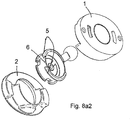
- the Fig. 9a shows the individual components in an exploded view.
- a novel spring locking element 9 is used. This spring locking element 9 is annular, wherein the ring forms the spring portion 9b.
- two locking pieces 9a1 and 9a2 are connected to the ring, that is, the spring locking element 9 is integrally formed.
- a bevel 9c which is identical to the bevel 9c from the Fig. 1 ,
- Fig. 9c is shown in the sectional view AA of the unlocked state in which the locking pieces 9a1 and 9a2 lie in the respective gap. This position was achieved by pivoting the actuator. At the same time, the magnet and the armature were pivoted to each other, so that the magnetic holding force was weakened. If there are two repulsive magnets, the shutter will pop up.
- the Fig. 9d shows a modification of the annular spring locking element 9. The same bending softness of the annular spring can also with the two in Fig. 9 shown semicircular individual springs can be achieved. The installation of these springs is in the Fig. 9e shown. In comparison shows Fig. 9f a single annular spring locking element and the Fig. 9g the built-in annular spring locking element.
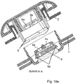
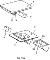
- the Fig. 10 indicates a modified closure Fig. 9 which can also be used for a satchel.
- the Fig. 10 a shows the individual components in an exploded view.
- a novel spring locking element is used.
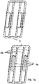
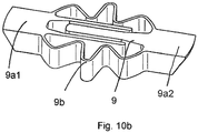
- the Fig. 10 b shows a perspective view of a first embodiment. Two locking pieces of the spring locking element are connected to each other via two corrugated leaf spring. Between the leaf springs, a fork-like guide is formed. The end portions of the locking pieces are chamfered. These and the following embodiment are very rigid.
- a similar embodiment shows the Fig. 10c However, the spring force is stronger than in the embodiment according to Fig. 10b when the same spring material is used.
- Another similar embodiment shows the Fig.
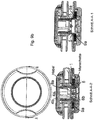
- the Fig. 10e shows a cross section of the closure and in particular the position and arrangement of the spring locking element, which is arranged in the closure center under the magnet-armature system. This allows the closure to be made smaller.
- connection modules When the connection modules are brought together, press the edges of the annular locking piece 5 on the inclined surfaces of the locking pieces 9a of the spring locking element 9, whereby it is compressed, so that the locking piece locks with the locking pieces, as in Fig. 10f shown.
- the knob the locking piece is rotated, so that the two gaps in the locking piece in opposing position with the locking pieces, whereby the lock is released.
- the Fig. 10g shows a sectional view of the closure and the position of the cutting plane.
- the Fig. 10h shows perspective views of the connection module, in which the spring locking element is arranged, with a plan view and a view from below, wherein in the view from below the spring locking element with two corrugated springs is recognizable.
- Fig. 10i are two perspective views of Connection module shown in which the rotatable locking piece is arranged with the gaps 6.
- Fig. 11 shows a further embodiment of the invention, in which the spring locking elements 9 are designed as separate spring jaws, which are movably mounted in the connecting module, as shown in FIGS Fig. 11a to 11c is apparent.
- the Fig. 11d shows the assembled state.
- the pressure-loaded locking pieces are particularly stable.
- Fig. 12 shows a clamp closure for use as a fixation for ice axes, hiking poles and the like on backpacks or bags or other closure applications in conjunction with a sewn on the backpack strap o.der Dermat, which is mounted in the slot on connection module 1. He is similar Fig. 7 a clamping, self-reinforcing positive engagement, but in which the magnet-armature construction is moved in rotation. Fig. 12a shows the closed state in which the bead-shaped locking pieces 5a, 5b are in positive engagement with the locking element 9. The structure and the function are from the Fig. 12b to 12e removable.
- Fig. 13 shows a hose coupling, the advantage is that it contracts by the magnetic force by itself and thus seals well.
- the basic constructive structure can be taken from the drawings 13a to 13h.
- Fig. 14 shows a coupling according to the same inventive principle, however, wherein the gap 6 is formed four times.
- the movement of magnet and locking piece is coupled via an indirect coupling with about 60 ° play, so that closing and opening position are synchronous.
- this embodiment is an example of a resilient Execution of the locking piece and an elastic deformation of locking piece and spring. The construction is from the Fig. 14a to 14c removable.
- Fig. 15 shows a Kippschnalle, in which a further form of the direction of movement, which was previously formed linear and rotating, is implemented.
- the basic structure and the function are from the 15a to 15d removable, wherein the Fig. 15b to d show an unlocked position, a closed position and an opening process in which the magnet / armature magnet system pivots against each other and is thereby poled to repulsion.
- the buckle is unlocked via the gap in the locking piece.
- Fig. 16a-f show a closure especially for bags, wherein the connection module 1 is mounted in the edge region and the closure is opened by a tilting lifting of the front edge.
- the magnet-armature system is pivoted against each other.
- a bearing of the two connection modules in an axis 30 and abutments 31a, b is provided. This bearing is advantageously designed so that the abutment released the axis only after pivoting.
- Fig. 17a-f shows a further embodiment of the tilting buckle similar Fig. 15 in which the spring locking element with springs 9b and locking piece 9a is advantageously developed by the curved portion of the locking spring 9c serves as an insertion aid when inserting the plug into the housing, the sensitive, resilient locking pieces 9a are protected inside and the locking element under load advantageous supported on the housing interior and the positive connection is reinforced.
- connecting modules are displaced against one another either in their entirety, ie rotating, tilting or sliding, or displaced against each other via an actuating device, ie magnet or armature are movably mounted in a connecting module ,
Landscapes
- Engineering & Computer Science (AREA)
- Textile Engineering (AREA)
- Buckles (AREA)
- Slide Fasteners, Snap Fasteners, And Hook Fasteners (AREA)
- Purses, Travelling Bags, Baskets, Or Suitcases (AREA)
- Electromagnets (AREA)
- Snaps, Bayonet Connections, Set Pins, And Snap Rings (AREA)
Description
Die Erfindung betrifft eine mechanisch-magnetische Verbindungskonstruktion, d. h. eine mechanische Verriegelung mittels Magnetkraftunterstützung, die besonders für Verschlüsse geeignet ist, wie sie an Taschen, Rucksäcken und vergleichbaren Gegenständen benutzt werden, wobei diese Aufzählung nicht den Einsatzbereich der Erfindung beschränken soll.Das Dokument
Eine weitere Hauptgruppe der Verbindungskonstruktionen sind die magnetisch wirkenden Verbindungskonstruktionen, in denen die Magnetkraft genutzt wird, die Verbindung zusammenzuhalten. Auch diese Verbindungskonstruktionen sind gerade für Verschlüsse von Taschen und anderen Behältnissen der Fachwelt hinreichend bekannt, so daß auch hier lediglich auf den Inhalt der Unterklassen von IPC E05C verwiesen wird.Another major group of connection constructions are the magnetically-acting connection structures in which the magnetic force is used to hold the connection together. These connection constructions are also well known for closures of bags and other containers of the art, so that also here only the contents of the subclasses of IPC E05C is referenced.
Weiterhin sind Kombinationen zwischen diesen beiden Hauptgruppen bekannt. Bei diesen Kombinationen wird in der Regel versucht, spezifische Anforderungen an eine Verbindungskonstruktion dadurch zu erfüllen, in dem gezielt die unterschiedlichen Eigenschaften einer mechanischen Verbindung und einer magnetischen Verbindungskonstruktionen kombiniert werden.Furthermore, combinations between these two main groups are known. In these combinations, it is usually attempted to meet specific requirements for a connection construction in that purpose the different Characteristics of a mechanical connection and a magnetic connection constructions are combined.
Nachfolgend sollen zur besseren Nachvollziehbarkeit der Vorteile der Erfindung zuerst einige Haupteigenschaften der mechanischen und der magnetischen Verbindungskonstruktionen diskutiert werden.In the following, for the sake of better understanding the advantages of the invention, first of all some of the main characteristics of the mechanical and magnetic connection constructions will be discussed.
Eine formschlüssige mechanische Verriegelung hat in der Regel ein mechanisches Bauteil, das bei Belastung der Verriegelung auf Zug, Druck oder Abscherung belastet wird. Die Größe des mechanischen Widerstandes dieses Bauteils definiert die Stabilität der Verbindungskonstruktion. Mechanische Verbindungskonstruktionen sind preiswert herstellbar, da z. B. bei Taschenverschlüssen lediglich sehr preiswerte Eisenteile oder Kunststoffteile verwendet werden.A positive mechanical lock usually has a mechanical component that is loaded when the lock is loaded to train, pressure or shearing. The size of the mechanical resistance of this component defines the stability of the connection structure. Mechanical connection structures are inexpensive to produce because z. B. in pocket closures only very inexpensive iron parts or plastic parts are used.
Diese mechanischen Verbindungskonstruktionen haben prinzipiell die Eigenschaft, daß beim Zusammenstecken manuell eine Verriegelungsfederkraft überwunden werden muß. Daher ist die Handhabung der Verbindungskonstruktionen in einigen Fällen nicht sehr komfortabel, so daß auf magnetischen Verbindungskonstruktionen zurückgegriffen wird, denn diese ziehen sich auf Grund der Magnetkraft von selbst zueinander.These mechanical connecting structures have in principle the property that when mating manually a locking spring force must be overcome. Therefore, in some cases, the handling of the connection constructions is not very comfortable, so that use is made of magnetic connection constructions, because these mutually pull themselves together due to the magnetic force.
Die beim Schließen und beim Öffnen an der Hand empfundene Kraft wird nachfolgend als Haptik bezeichnet. Gerade bei Verschlüssen, die von Hand betätigt werden, muß die Haptik der menschlichen Handkraft angepaßt werden.The force felt when closing and opening on the hand is referred to below as haptic. Especially with closures that are operated by hand, the feel of the human hand force must be adjusted.
Bei Magnetverbindungen, bei denen die Magnetkraft direkt dazu verwendet wird, das Öffnen der Verbindung zu verhindern, müssen der Magnet und der dazugehörige Anker entsprechend der Haltekraft dimensioniert sein. Wenn keine besonderen Anforderungen an die Zuhaltekraft und an die Haptik gestellt werden, sind diese Verbindungen praxistauglich.For magnetic connections in which the magnetic force is used directly to prevent the opening of the connection, the magnet and the associated anchor must be dimensioned according to the holding force. If no special requirements are placed on the locking force and the haptics, these connections are practical.
Die Verschlüsse müssen in bestimmten Fällen jedoch überdimensioniert sein, wenn z. B. Sicherheitsanforderungen zu erfüllen sind. Das kann z. B. bei einem Rucksack für Bergsteiger gefordert sein. Dieser Rucksack darf sich auch dann nicht öffnen, wenn der Verschluß mit einem Vielfachen der normalen Haltekraft belastet wird, was z. B. bei einem Absturz eintreten kann. Insofern werden Verschlüsse mit einem derartigen Anforderungsprofil als mechanische Verschlüsse ausgebildet, da mit mechanischen Konstruktionen auch hohe Sicherheitsfaktoren ohne großen Mehraufwand realisierbar sind. Insofern haben sich diese Verbindungskonstruktionen am Massenmarkt durchgesetzt.The closures must be oversized in certain cases, however, if z. B. safety requirements are met. This can z. B. be required in a backpack for mountaineers. This backpack is also allowed not open when the shutter is loaded with a multiple of the normal holding force, which z. B. may occur in a crash. In this respect, closures are designed with such a requirement profile as mechanical closures, since with mechanical structures and high safety factors can be realized without much additional effort. In this respect, these connection constructions have prevailed on the mass market.
Weiterhin sind aus dem Stand der Technik verschiedene mechanische Verbindungskonstruktionen bekannt, bei denen zusätzlich zu einer mechanischen Verriegelung auch noch Magnete eingesetzt werden. Die Magnete dienen jedoch lediglich dazu, die mechanische Verriegelung im Schließzustand zusammenzuhalten. Dabei wird die Magnetkraft anstelle der Federkraft einer mechanischen Feder genutzt. Diese Konstruktionen weisen keine angenehme Haptik auf. Sie lassen sich meist relativ leicht schließen, jedoch schwieriger öffnen.Furthermore, various mechanical connection constructions are known from the prior art in which magnets are used in addition to a mechanical locking. However, the magnets only serve to hold together the mechanical lock in the closed state. The magnetic force is used instead of the spring force of a mechanical spring. These constructions do not have a pleasant feel. They are usually relatively easy to close, but difficult to open.
Für folgende Anforderungen ist aus dem Stand der Technik keine Verbindungskonstruktion bekannt:
- a. Verriegelung erfolgt mechanisch,
- b. Verbindungskonstruktion zieht sich von selbst in Hauptbelastungsrichtung zusammen
- c. Verbindungskonstruktion läßt sich leicht öffnen, d. h. weist eine gute Haptik auf
- a. Locking is done mechanically,
- b. Connecting construction contracts by itself in the main load direction
- c. Connection construction is easy to open, ie has a good feel
Es ist demzufolge die Aufgabe der Erfindung, eine Verbindungskonstruktion bereitzustellen, die alle drei Anforderungen a bis c gleichzeitig erfüllt.It is therefore the object of the invention to provide a connecting structure that meets all three requirements a to c at the same time.
Diese Aufgabe wird mit einer mechanisch-magnetischen Verbindungskonstruktion nach Anspruch 1 gelöst. Diese Verbindungskonstruktion weist zwei Verbindungsmodule auf und dient zum Verbinden von zwei Elementen, an denen jeweils eines der Verbindungsmodule befestigbar ist.This object is achieved with a mechanical-magnetic connection construction according to
Die Verbindungskonstruktion weist nachfolgende Merkmale auf:
- Eine Verriegelungsvorrichtung mit wenigstens einem Federverriegelungselement, das in einem der Verbindungsmodule angeordnet ist, und einem bewegbaren Sperrstück zum formschlüssigen Verriegeln der Verbindungsmodule, das in dem anderen Verbindungsmodul angeordnet ist. Das Federverriegelungselement ist so ausgebildet, daß es beim Schließen der Verbindungskonstruktion gegen das Sperrstück gedrängt wird. Das Federverriegelungselement, das Sperrstück und die miteinander in Berührung kommenden Flächenabschnitte des Federverriegelungselements und des Sperrstücks sind so ausgebildet, daß das Federverriegelungselement in eine konstruktiv festgelegte Richtung ausgelenkt wird und in das Sperrstück einschnappt, wenn sich das Verriegelungselement und das Sperrstück relativ aufeinander zu bewegen. Es ist dem Fachmann klar, daß die Verwendung des Begriffs "Feder" lediglich die Eigenschaft "federnd" beschreiben soll. Demzufolge fallen auch alle Ausführungsformen darunter, bei denen elastische Materialien eingesetzt werden. Es ist weiterhin klar, daß die "federnde" oder die "elastische" Eigenschaft auch dem Sperrstück zugeordnet werden kann, wobei die federnde oder elastische Auslenkung des Sperrstücks nicht identisch ist mit der Verschiebung des Sperrstücks zum Öffnen.
- A locking device having at least one spring locking element, which is arranged in one of the connection modules, and a movable locking piece for form-locking locking of the connection modules, which is arranged in the other connection module. The spring locking element is designed so that it is urged against the locking piece when closing the connecting structure. The spring locking element, the locking piece and the mutually contacting surface portions of the spring locking element and the locking piece are formed so that the spring locking element is deflected in a constructively fixed direction and snaps into the locking piece when the locking element and the locking piece to move relative to each other. It is clear to those skilled in the art that the use of the term "spring" is intended to describe only the property "resilient". As a result, all embodiments fall under which elastic materials are used. It is also clear that the "resilient" or the "elastic" property can also be assigned to the locking piece, wherein the resilient or elastic deflection of the locking piece is not identical to the displacement of the locking piece for opening.
Das Sperrstück und das Verriegelungselement sind so ausgebildet, daß die mechanische Festigkeit in Abhängigkeit von den tatsächlich auftretenden oder möglichen Belastungen ausreichend ist.The locking piece and the locking element are formed so that the mechanical strength is sufficient depending on the actual occurring or possible loads.
Weiterhin ist das Sperrstück bewegbar, so daß es von einer Eingriffsposition, in der das Federverriegelungselement in Eingriff mit dem Sperrstück ist, in eine Nichteingriffsposition bringbar ist, in der das Federverriegelungselement nicht in Eingriff mit dem Sperrstück ist. Diese Merkmalskombination soll nachfolgend näher erläutert werden:
- Wenn die Verbindungskonstruktion zusammengeschnappt ist, liegt eine formschlüssige Verbindung vor. Um den Formschluß zu lösen, wird das bewegbare Sperrstück in eine Richtung bewegt, in der das Sperrstück nicht mehr in Eingriff mit dem Federverriegelungselement steht, d. h. es wird von der Eingriffsposition in die Nichteingriffsposition bewegt.
- If the connection construction snaps together, there is a positive connection. In order to release the positive engagement, the movable locking piece is moved in a direction in which the locking piece is no longer in engagement with the spring locking element, that is, it is moved from the engagement position to the disengaged position.
Ist das Sperrstück z. B. ein Stab und das Federverriegelungselement hat einen Hakenkopf, der beim Schließen gegen den Stab gedrückt wird, dann lenkt das Federverriegelungselement aus und schnappt danach ein, wobei sich der Hakenkopf hinter den Stab hakt, d. h. in der Eingriffsposition ist.Is the locking piece z. As a rod and the spring locking element has a hook head, which is pressed against the rod when closing, then deflects the spring locking element and then snaps, with the hook head hooks behind the rod, d. H. in the engaged position.
Als weiteres Merkmal hat das Sperrstück eine Ausnehmung, nachfolgend als Lücke bezeichnet. Wenn das Sperrstück relativ zum Federverriegelungselement so verschoben wird, daß der Hakenkopf und die Lücke in Gegenüberlage stehen, ist keine formschlüssige Verbindung mehr gegeben, denn die Lücke ist so dimensioniert, daß der Hakenkopf in der Lücke keinen Halt findet. Es ist dem Fachmann klar, daß auch das Ende des Sperrstücks die Wirkung der vorstehend beschriebenen Lücke hat, d. h. wenn kein Sperrstück mehr vorhanden ist, kann der beispielhaft erwähnte Hakenkopf keinen Halt mehr finden. Weiterhin ist dem Fachmann klar, dass diese Verschiebung auch drehend oder kippend vonstatten gehen kann.As a further feature, the locking piece has a recess, hereinafter referred to as a gap. If the locking piece is displaced relative to the spring locking element so that the hook head and the gap are in opposition, no positive connection is no longer given, because the gap is dimensioned so that the hook head in the gap does not find support. It is clear to those skilled in the art that also the end of the locking piece has the effect of the gap described above, i. H. if no more locking piece is present, the example mentioned hook head can no longer find a hold. Furthermore, it is clear to those skilled in the art that this shift can also be rotational or tilting.
Die Verbindungskonstruktion weist weiterhin eine Magnet-Anker-Konstruktion auf, wobei in einem der Verbindungsmodule der Magnet und in dem anderen Verbindungsmodul der Anker angeordnet ist. Die Magnetkraft zwischen Anker und Magnet ist so groß gewählt, daß beim Schließvorgang die Verbindungsmodule ab einem vorbestimmten Mindestabstand zueinander gezogen werden, wodurch das Federverriegelungselement gegen das Sperrstück drängt, bis es in Eingriff schnappt. Mit anderen Worten, Magnet und Anker sind so dimensioniert, daß die Federkraft des Federverriegelungselements überwunden wird. Hier ist dem Fachmann klar, dass Magnet-Anker-Konstruktionen nicht nur aus einem einzelnen Magneten und einem einzelnen Anker bestehen können. Nachfolgend wird daher unter einer Magnet-Anker-Konstruktionen jede Art Kombination von Magneten und Ankern verstanden, die sich wenigsten zueinander ziehen, wobei dem Fachmann bekannt ist, daß der Anker aus einem ferromagnetischen Material besteht oder auch ein Magnet sein kann. Bestimmte Magnet-Anker-Konstruktionen ziehen sich nicht nur an, sondern können sich auch abstoßen, wenn zwei gleichnamige Magnetpole in Gegenüberlage gebracht werden. Wenn nicht besondere zusätzliche Bedingungen gelten, ist es gleichgültig, ob der Magnet gegenüber dem Anker oder der Anker gegenüber dem Magnet bewegt wird. Es ist auch klar, daß die Wirkbeziehung zwischen Magnet und Anker die gleiche ist wie zwischen zwei anziehenden Magneten.The connection construction furthermore has a magnet armature construction, wherein the magnet is arranged in one of the connection modules and the armature is arranged in the other connection module. The magnetic force between armature and magnet is chosen so large that during the closing operation, the connection modules are pulled from a predetermined minimum distance from each other, whereby the spring locking element urges against the locking piece until it snaps into engagement. In other words, magnet and armature are dimensioned so that the spring force of the spring locking element is overcome. It will be clear to those skilled in the art that magnet-armature constructions can not consist of only a single magnet and a single armature. Below is therefore understood by a magnet-armature constructions every kind of combination of magnets and anchors that pull at least to each other, the skilled man is known that the armature consists of a ferromagnetic material or may be a magnet. Certain magnetic anchor designs not only attract, but can also repel when opposing two magnetic poles of the same name. Unless special additional conditions apply, it does not matter if the magnet is moved relative to the armature or the armature is opposite to the magnet. It is also clear that the interaction between magnet and armature is the same as between two magnet attracting.
Wenn die Verbindungsmodule verbunden sind, besteht eine mechanische Verriegelung und auch eine magnetische Anziehung. Es ist jedoch zu betonen, daß die magnetische Anziehung nur einen unwesentlichen Teil der Hauptbelastungskraft der Verbindung aufnimmt. Die Magnet-Anker-Konstruktion dient nahezu ausschließlich dem selbsttätigen Schließen der Verbindung.When the connection modules are connected, there is a mechanical lock and also a magnetic attraction. It should be noted, however, that magnetic attraction absorbs only a negligible part of the main load of the connection. The magnetic anchor construction almost exclusively serves to automatically close the connection.
Damit beim Trennen des Magneten vom Anker eine eingangs erwähnte angenehme Haptik entsteht, werden Verbindungsmodul 1 mit dem Magnet und verbindungsmodul 2 mit dem Anker seitlich zueinander so weit verschoben, bis die Magnetkraft ausreichend geschwächt ist, um die Module leicht von Hand trennen zu können. Das ist dann der Fall, wenn die dem Magneten gegenüber stehende Ankerfläche hinreichend klein geworden ist. Es ist klar, daß die Verschiebung zwischen dem Magneten und dem Anker auch eine Verdrehung oder ein Verschwenken sein kann.Thus, when disconnecting the magnet from the anchor an initially mentioned pleasant feel,
Der bewegbare Magnet ist mit dem Sperrstück gekoppelt, d. h. mit dem Magneten wird auch das Sperrstück bewegt, wobei der Begriff "gekoppelt" nicht nur bedeutet, daß das Sperrstück mit dem Magnet starr verbunden sein muß. Unter einer Kopplung ist auch eine Verbindung über eine Feder zu verstehen. Eine Kopplung ist auch dann vorhanden, wenn ein Mitnehmer das Sperrstück verschiebt, dieser Mitnehmer aber nicht immer an dem Sperrstück anliegt, d. h. wenn ein Spiel vorhanden ist. Diese Zusammenhänge werden in der Beschreibung der Ausführungsbeispiele noch näher erläutert.The movable magnet is coupled to the locking piece, i. H. with the magnet and the locking piece is moved, wherein the term "coupled" not only means that the locking piece must be rigidly connected to the magnet. A coupling also means a connection via a spring. A coupling is also present when a driver moves the locking piece, but this driver is not always applied to the locking piece, d. H. if a game exists. These relationships are explained in more detail in the description of the embodiments.
Nachfolgend wird die Haupteigenschaft der Erfindung zusammengefaßt:
- Wenn der Magnet weit genug vom Anker verschoben wurde, so daß die magnetische Anziehungskraft zwischen Anker und Magnet ausreichend schwach ist, befindet sich gleichzeitig das Federverriegelungselement in der Lücke des Sperrstücks, d. h. in der Nichteingriffsposition. In dieser Position ist die Verbindungsvorrichtung sowohl mechanisch entriegelt als auch magnetisch gelöst. Beim mechanischen Entriegeln war es nicht notwendig, das Federverriegelungselement zu bewegen, d. h. die Federkraft des Federverriegelungselements wird lediglich beim Schließen durch die Magnetkraft überwunden, beim Öffnen ist die Federkraft Null, da das Federverriegelungselement nicht ausgelenkt wird.
- When the magnet has been moved far enough away from the armature so that the magnetic attraction between armature and magnet is sufficiently weak, the spring locking element is simultaneously in the gap of the locking piece, ie in the disengaged position. In this position, the connecting device is both mechanically unlocked and released magnetically. When unlocking mechanically, it was not necessary to the spring locking element move, ie the spring force of the spring locking element is overcome only when closing by the magnetic force, when opening the spring force is zero, since the spring locking element is not deflected.
Somit ist verständlich, daß diese Verbindungskonstruktion eine besonders weiche Öffnungshaptik aufweist, denn zum Öffnen muß lediglich die Magnetkraft durch das seitliche Verschieben von Magnet und Anker geschwächt oder ganz aufgehoben werden. Andererseits ist die Verbindungskonstruktion im Verbundzustand so stabil wie eine mechanische Verbindungskonstruktion.Thus, it is understood that this connection structure has a particularly soft opening feel, because to open only the magnetic force must be weakened by the lateral displacement of the magnet and armature or canceled altogether. On the other hand, the connection construction in the composite state is as stable as a mechanical connection construction.
Es ist klar, daß beim Schließen der Verbindungskonstruktion die vorstehend beschriebene Position zwischen Sperrstück und Lücke und zwischen Anker und Magnet nicht vorliegen darf, d. h. beim Schließen müssen sich Sperrstück und Federverriegelungselement so gegenüber stehen, daß es zum Einschnappen kommen kann. Andererseits müssen sich beim Schließen auch der Magnet und der Anker in einer Position gegenüber stehen, in der die Magnetkraft zwischen Magnet und Anker stark genug ist, um die Federkraft des Federverriegelungselements zu überwinden, damit der Einschnappvorgang erfolgen kann. Mit anderen Worten gesagt, muß vor dem Verbinden der Verbindungskonstruktion dafür gesorgt werden, daß die Verriegelungskonstruktion und die Magnet-Anker-Konstruktion in ihrer jeweiligen Ausgangsposition stehen, die das Zusammenziehen und das Einschnappen ermöglicht. Diese Rückstellung der Funktionselemente der Verriegelungskonstruktion und der Magnet-Anker-Konstruktion wird durch Rückstellmittel bewirkt. Dem Fachmann ist bekannt, wie mechanische Bauteile von einer Position in eine zweite Position bringbar sind. Dazu muß lediglich eine Kraft an dem Bauteil angreifen. Bei der vorliegenden Erfindung wird vorzugsweise die Kraft einer Rückstellfeder verwendet, die beim Öffnen der Verbindungskonstruktion vorgespannt wird. Dem Fachmann ist klar, daß diese Rückstellfeder lediglich so stark sein muß, um die beim Öffnen bewegten Funktionselemente wieder in ihre Ausgangsposition zu drängen. Dazu ist lediglich eine sehr geringe Kraft erforderlich, so daß nur eine schwache Rückstellfeder erforderlich ist, so daß die eingangs erwähnte weiche und angenehme Haptik erhalten bleibt.It is clear that when closing the connecting structure, the above-described position between locking piece and gap and between armature and magnet must not be present, ie when closing the locking piece and spring locking element must face each other so that it can come to snapping. On the other hand, when closing, the magnet and the armature must also be in a position in which the magnetic force between the magnet and the armature is strong enough to overcome the spring force of the spring locking element, so that the snap-action can take place. In other words, before connecting the connecting structure, the locking structure and the magnetic anchor construction must be made to be in their respective initial position, which allows for contraction and snapping. This provision of the functional elements of the locking structure and the magnet-armature construction is effected by return means. The skilled worker is aware of how mechanical components can be brought from a position to a second position. All that needs to do is to apply a force to the component. In the present invention, preferably, the force of a return spring is used, which is biased when opening the connecting structure. It will be clear to those skilled in the art that this return spring need only be so strong as to urge the functional elements moved during opening back into their starting position. For this purpose, only a very small force is required, so that only a weak return spring is required, so that the aforementioned soft and pleasant feel is maintained.
Die Rückstellung kann jedoch auch magnetisch erfolgen. Dieser Effekt ist dem Fachmann hinreichend bekannt, so daß nur eine Möglichkeit von vielen erläutert wird: Wenn ein Anker und ein Magnet aneinander haften, dann kann diese magnetische Haftverbindung gelöst werden, in dem der Anker vom Magneten abgeschoben wird. Wenn die sich anziehenden Flächen von Magnet und Anker gleich groß sind, dann verkleinert sich der anziehende Flächenabschnitt, wenn Anker und Magnet seitlich voneinander abgeschoben werden. Beim Abschieben muß eine Rückstellkraft überwunden werden, denn Magnet und Anker werden durch die Magnetkraft in der Ausgangsposition gehalten. Je kleiner die Reibung zwischen den sich anziehenden Flächen ist, um so größer ist die Rückstellkraft. Dieser dem Fachmann bekannt Effekt kann noch verstärkt werden, wenn Magnet und Anker bestimmte Formen und/oder Magnetisierungen aufweisen. So ist z. B. klar, daß sich eine dreieckige Ankerfläche bei geeigneter Magnetisierung nach einer ebenfalls dreieckigen Magnetfläche ausrichtet.However, the provision can also be made magnetically. This effect is well known to those skilled in the art, so that only one possibility is explained by many: If an anchor and a magnet adhere to each other, then this magnetic bond can be solved by pushing the anchor off the magnet. If the attracting surfaces of magnet and armature are the same size, then the attracting surface portion decreases when the armature and magnet are laterally deported from each other. When pushing off a restoring force must be overcome, because magnet and armature are held by the magnetic force in the starting position. The smaller the friction between the attracting surfaces, the greater the restoring force. This effect, which is known to the person skilled in the art, can be enhanced if the magnet and the armature have certain shapes and / or magnetizations. So z. B. clear that a triangular armature surface aligns with a suitable magnetization for a likewise triangular magnetic surface.
Nach einer vorteilhaften Weiterbildung der Erfindung nach Anspruch 2 weist die Magnet-Ankerkonstruktion mehrere Verriegelungselemente oder ein Verriegelungselement mit mehreren Verriegelungsabschnitten auf. Mit dieser Weiterbildung der Erfindung ist es z. B. möglich, die angreifende Kraft besser zu verteilen.According to an advantageous embodiment of the invention according to
Nach einer vorteilhaften Weiterbildung der Erfindung nach Anspruch 3 weist die Magnet-Ankerkonstruktion eine Koppelvorrichtung auf, die in der Bewegungsrichtung des bewegbaren Magneten ein Spiel hat, so daß das Sperrstück mittels eines Anschlags erst dann in die Richtung des Magneten gezogen wird, wenn das Spiel aufgebraucht ist. Der Vorteil dieser Ausführungsform besteht darin, daß der Verschiebeweg des Magneten vom Anker größer sein kann als der Weg, den das Sperrstücks verschoben werden muß, bis die Lücke in Gegenüberlage zum Federverriegelungselement steht. Mit dieser Ausführungsform können Verbindungskonstruktion gebaut werden, bei denen der Verschiebeweg des Magneten vom Anker bedingt durch konstruktive Randbedingungen größer sein muß als der Weg, den das Sperrstück bewegt wird.According to an advantageous embodiment of the invention according to
Nach einer vorteilhaften Weiterbildung der Erfindung nach Anspruch 4 weist die Magnet-Ankerkonstruktion als Koppelvorrichtung eine Koppelfeder auf, deren Federkraft sich entlang der Bewegungsrichtung des Magneten und des Sperrstücks erstreckt. Der Vorteil dieser Ausführungsform besteht darin, daß mit dieser Merkmalskombination eine Sicherheit gegen das Öffnen der Verbindungskonstruktion unter Belastung geschaffen wurde. Die Feder ist so dimensioniert, daß im unbelasteten Zustand der mechanischen Verriegelungsvorrichtung beim Verschieben des Magneten über die Koppelvorrichtung auch das Sperrstück mitgezogen wird. Im belasteten Zustand ist die Reibkraft zwischen dem Federverriegelungselement und dem Sperrstück größer als die Federkraft, d. h. der Magnet kann z. B. von Hand verschoben werden, ohne das sich die mechanische Verriegelung öffnet. Wenn in diesem Zustand die mechanische Verriegelung entlastet wird, zieht oder drückt die Feder das Sperrstück in die Öffnungsrichtung, so daß sich die Verbindung sofort öffnen läßt.According to an advantageous embodiment of the invention according to
Nach einer vorteilhaften Weiterbildung der Erfindung nach Anspruch 5 weist die Magnet-Ankerkonstruktion eine Koppelvorrichtung auf, die in der Bewegungsrichtung des bewegbaren Magneten ein Spiel hat, so daß das Sperrstück mittels eines Anschlags erst dann in die Richtung des Magneten gezogen wird, wenn das Spiel aufgebraucht ist. Weiterhin ist eine Rückstellzugfeder für das Sperrstück vorgesehen, deren Federkraft sich entlang der Bewegungsrichtung des Sperrstücks erstreckt. Wenn der Magnet vom Anker verschoben wird und das Spiel der Koppelvorrichtung aufgebraucht ist, wird die Rückstellfeder gedehnt. Wenn die Verbindung gelöst ist, ziehen sich Magnet und Anker in Gegenüberlage und gleichzeitig wird das Sperrstück in seine Ausgangslage gezogen.According to an advantageous embodiment of the invention according to
Nach einer vorteilhaften Weiterbildung der Erfindung nach Anspruch 6 weist die Magnet-Ankerkonstruktion eine Koppelvorrichtung auf, die in der Bewegungsrichtung des bewegbaren Magneten ein Spiel hat, so daß das Sperrstück mittels eines Anschlags erst dann in die Richtung des Magneten gezogen wird, wenn das Spiel aufgebraucht ist. Weiterhin ist eine Rückstelldruckfeder für das Sperrstück vorgesehen, deren Federkraft sich entlang der Bewegungsrichtung des Sperrstücks erstreckt. Wenn der Magnet vom Anker verschoben wird und das Spiel der Koppelvorrichtung aufgebraucht ist, wird die Rückstellfeder gestaucht. Wenn die Verbindung gelöst ist, ziehen sich Magnet und Anker in Gegenüberlage und gleichzeitig wird das Sperrstück in seine Ausgangslage geschoben.According to an advantageous embodiment of the invention according to
Aus den Unteransprüchen 3 bis 6 ist für den Fachmann erkennbar, daß es noch eine Vielzahl von Kombinationen dieser Art gibt, bei denen Anschläge, Mitnehmer und Federn zu Einsatz kommen, die sich jedoch alle dem gleichen Erfindungsgedanken unterordnen, so daß der Fachmann je nach technischen Randbedingungen eine geeignete Kombination auswählen kann, ohne das dazu eine erfinderische Tätigkeit erforderlich ist. Insbesondere können Zug- und Druckfedern kombiniert werden.From the
Nach einer vorteilhaften Weiterbildung der Erfindung nach Anspruch 7 ist eine von Hand oder mit dem Fuß betätigbare Betätigungsvorrichtung zum Bewegen des Magneten oder des Ankers vorgesehen, welcher in einem der beiden Verbindungsmodule beweglich gelagert ist.According to an advantageous development of the invention according to
Nach einer vorteilhaften Weiterbildung der Erfindung nach Anspruch 8 ist an einem der Verbindungsmodule ein von Hand greifbarer Gegenstand vorgesehen ist, der von Hand auf das andere Verbindungsmodul aufsetzbar ist. Diese Ausführungsform der Erfindung eignet sich z. B. dafür, um eine Fahrradlampe mit dem Fahrradlenker zu verbinden. In diesem Fall ist der Anker direkt mit dem Gegenstand einstückig verbunden.According to an advantageous embodiment of the invention according to
Nach einer vorteilhaften Weiterbildung der Erfindung nach Anspruch 9 weist die Magnet-Ankerkonstruktion in einem Verbindungsmodul wenigstens einen Magneten und in dem anderen Verbindungsmodul wenigstens einen ferromagnetischen Anker oder einen auf Anziehung gepolten Magneten auf. Diese Anordnung wird bevorzugt, wenn eine kostengünstige Verbindung benötigt wird.According to an advantageous development of the invention according to
Nach einer vorteilhaften Weiterbildung der Erfindung nach Anspruch 10 weist die Magnet-Ankerkonstruktion in einem Verbindungsmodul einen Magneten mit zwei ferromagnetischen Leitblechen und in dem anderen Verbindungsmodul einen ferromagnetischen Anker auf, wobei die Leitbleche so angeordnet sind, daß sie in magnetischer Wirkbeziehung mit dem ferromagnetischen Anker stehen und der Magnet den Anker nicht berührt. Diese Anordnung wird bevorzugt, wenn eine robuste Verbindung benötigt wird, denn bei dieser Magnet-Ankerkonstruktion erfolgt keine mechanische Berührung der Magnetoberfläche mit der Oberfläche des Ankers, so daß eine Beschädigung der empfindlichen Magnetoberfläche z.B. beim wiederholten Verschieben vermieden wird, selbst wenn Fremdkörper wie z. B. Sand dazwischen liegen.According to an advantageous development of the invention according to
Nach einer vorteilhaften Weiterbildung der Erfindung nach Anspruch 11 weist die Magnet-Ankerkonstruktion in einem Verbindungsmodul einen Magneten mit einem ferromagnetischen Leitblech und in dem anderen Verbindungsmodul einen ferromagnetischen Anker auf, wobei der Magnet und das Leitbleche so angeordnet sind, daß sie in magnetischer Wirkbeziehung mit dem ferromagnetischen Anker stehen. Diese Anordnung wird bevorzugt, wenn die Magnetkraft besonders gut ausgenutzt werden soll, was durch die Bündelung der Magnetfeldlinien in dem Magnetleitblech erreicht wird.According to an advantageous embodiment of the invention according to
Nach einer vorteilhaften Weiterbildung der Erfindung nach Anspruch 12 weist die Magnet-Ankerkonstruktion in jedem Verbindungsmodul einen Magneten mit ferromagnetischen Leitblechen auf, wobei die Leitbleche in Schließstellung sich anziehend gegenüber stehen. Diese Anordnung wird bevorzugt, wenn eine robuste Verbindung mit einer hoher Anzugskraft im Schließzustand benötigt wird, und wenn beim Öffnen eine zumindest geringe Abstoßung erwünscht ist.According to an advantageous embodiment of the invention according to
Nach einer vorteilhaften Weiterbildung der Erfindung nach Anspruch 13 weist die Magnet-Ankerkonstruktion wenigsten je zwei sich gegenüber liegenden Magnete auf, die in der Schließstellung der Verbindung beide in einer Anzugsposition und bei der Offenstellung beide in einer Abstoßposition sind. Diese Anordnung wird bevorzugt, wenn eine Verbindung mit hoher Anzugskraft im Schließzustand und mit hoher Abstoßungskraft beim Öffnen benötigt wird.According to an advantageous embodiment of the invention according to
Nach einer vorteilhaften Weiterbildung der Erfindung nach Anspruch 14 weist die Magnet-Ankerkonstruktion eine Magnetanordnung auf, bei der in jedem Verbindungsmodul ein Magnet und ein ferromagnetischer Anker so angeordnet sind, daß im Schließzustand die Magnete in Gegenüberlage der Anker sind und im Offenzustand sich die auf Abstoßung gepolten Magnete gegenüber stehen. Diese Anordnung wird bevorzugt, wenn eine kostengünstige Verbindung mit hoher Anzugskraft im Schließzustand und mit geringer Abstoßungskraft beim Öffnen benötigt wird.
Die Erfindung wird nachfolgend mit Hilfe von Ausführungsbeispielen und dazugehörigen Zeichnungen näher erläutert:
- Fig. 1a - e
- zeigt eine Prinzipdarstellung der Erfindung
- Fig. 1f
- zeigt einen besonderen Anwendungsfall der Erfindung
- Fig. 2a - b
- zeigt eine Prinzipdarstellung der Erfindung mit einer ersten speziellen Koppelvorrichtung
- Fig. 3a - b
- zeigt eine Prinzipdarstellung der Erfindung mit einer zweiten speziellen Koppelvorrichtung
- Fig. 4a - b
- zeigt eine Prinzipdarstellung der Erfindung mit einer dritten speziellen Koppelvorrichtung
- Fig. 5a - c
- zeigt eine Prinzipdarstellung der Erfindung mit einer vierten speziellen Koppelvorrichtung
- Fig. 6
- zeigt die Erfindung in einem ersten speziellen Ausführungsbeispiel
- Fig. 7
- zeigt die Erfindung in einem weiteren speziellen Ausführungsbeispiel
- Fig. 8
- zeigt die Erfindung in einem weiteren speziellen Ausführungsbeispiel
- Fig. 9
- zeigt die Erfindung in einem weiteren speziellen Ausführungsbeispiel
- Fig. 10
- zeigt die Erfindung in einem weiteren speziellen Ausführungsbeispiel
- Fig. 11
- zeigt die Erfindung in einem weiteren speziellen Ausführungsbeispiel
- Fig. 12
- zeigt die Erfindung in einem weiteren speziellen Ausführungsbespiel
- Fig. 13
- zeigt die Erfindung in einem weiteren speziellen Ausführungsbespiel
- Fig. 14
- zeigt die Erfindung in einem weiteren speziellen Ausführungsbespiel
- Fig. 15
- zeigt die Erfindung in einem weiteren speziellen Ausführungsbespiel
- Fig 16
- zeigt die Erfindung in einem weiteren speziellen Ausführungsbespiel
- Fig 17
- zeigt die Erfindung in einem weiteren speziellen Ausführungsbespiel
The invention is explained in more detail below with the aid of exemplary embodiments and associated drawings:
- Fig. 1a - e
- shows a schematic diagram of the invention
- Fig. 1f
- shows a particular application of the invention
- Fig. 2a - b
- shows a schematic diagram of the invention with a first special coupling device
- Fig. 3a - b
- shows a schematic diagram of the invention with a second special coupling device
- Fig. 4a - b
- shows a schematic diagram of the invention with a third special coupling device
- Fig. 5a - c
- shows a schematic diagram of the invention with a fourth special coupling device
- Fig. 6
- shows the invention in a first specific embodiment
- Fig. 7
- shows the invention in a further specific embodiment
- Fig. 8
- shows the invention in a further specific embodiment
- Fig. 9
- shows the invention in a further specific embodiment
- Fig. 10
- shows the invention in a further specific embodiment
- Fig. 11
- shows the invention in a further specific embodiment
- Fig. 12
- shows the invention in a further specific embodiment
- Fig. 13
- shows the invention in a further specific embodiment
- Fig. 14
- shows the invention in a further specific embodiment
- Fig. 15
- shows the invention in a further specific embodiment
- FIG. 16
- shows the invention in a further specific embodiment
- Fig. 17
- shows the invention in a further specific embodiment
- 1.1.
- Verbindungsmodulconnecting module
- 2.Second
- Verbindungsmodulconnecting module
- 3.Third
- Trennlinieparting line
- 4.4th
- Magnetmagnet
- 5.5th
- Sperrstücklocking piece
- 6.6th
- Lückegap
- 7.7th
- Koppelvorrichtungcoupling device
- 7a.7a.
- Koppelplattecoupling plate
- 7b.7b.
- Koppelausnehmungcoupling recess
- 7c.7c.
- KoppeleingriffsstückCoupling engagement piece
- 7d.7d.
- Koppelspielcoupling play
- 8.8th.
- Anker, AnkermagnetAnchor, anchor magnet
- 9.9th
- FederverriegelungselementSpring locking element
- 9a.9a.
- Verriegelungsstück des FederverriegelungselementsLocking piece of the spring locking element
- 9b.9b.
- Federabschnitt des FederverriegelungselementsSpring section of the spring locking element
- 10a.10a.
- Sperrstück-RückstellfederBlocking piece return spring
- 10b.10b.
- Magnet-RückstellfederMagnetic return spring
- 10c.10c.
- Magnet-Sperrstück-KoppelfederMagnetic locking piece coupling spring
Mit der Prinzipdarstellung in
Mit den Bezugszeichen 1 und 2 sind die zu verbindenden Verbindungsmodule bezeichnet, die zur Erhöhung der Übersichtlichkeit durch eine Trennlinie 3 getrennt sind. Beide Verbindungsmodule stehen sich also getrennt, d. h. beabstandet gegenüber.The
Das Verbindungsmodul 1 besteht aus einem Magneten 4, einem Sperrstück 5 mit einer Lücke 6. Das Sperrstück 5 ist über eine Koppelvorrichtung 7 mit dem Magneten 4 verbunden.The connecting
Das Verbindungsmodul 2 besteht aus einem ferromagnetischen Anker 8 und einem Federverriegelungselement 9, welches ein Verriegelungsstück 9a und einen Federabschnitt 9b aufweist. Wenn sich das bewegbare Verbindungsmodul 2 in Pfeilrichtung A dem fest stehenden Verbindungsmodul 1 nähert, dann wird eine Position nach
In dieser Position liegt das Verriegelungsstück 9a mit einer Eingriffsfläche 9c, die angeschrägt sein kann, an dem Sperrstück 5 an. Mittels der Magnetkraft F zwischen den Magneten 4 und 8 wird das federnd gehaltene Verriegelungsstück 9a gegen die Unterkante des Sperrstücks 5 gedrängt. Die Magnetkraft F und die Federkonstante des Federabschnitt 9b sind so bemessen, daß der Federabschnitt 9b in Pfeilrichtung zurückfedert, so daß eine Position nach
In dieser Zwischenposition gleitet das Verriegelungsstück 9a in Pfeilrichtung zurück. Wenn es die Oberkante des Sperrstücks 5 erreicht hat, drängt der Federabschnitt 9b das Verriegelungsstück 9a in die in
In dieser Position sind die Magnetfläche und die Ankerfläche in Berührung oder dicht beieinander und das Verriegelungsstück 9a liegt nun auf der Oberfläche des Sperrstücks 5, d. h. die Verriegelung ist zugeschnappt. Es ist somit nicht mehr möglich, das Verbindungsmodul 2 in Pfeilrichtung B zu ziehen, da die Verriegelung das verhindert.In this position, the magnetic surface and the armature surface are in contact or close to each other and the
Es ist zu betonen, daß die Magnetkraft für die Festigkeit der Verbindung keinen wesentlichen Einfluß hat.It should be emphasized that the magnetic force has no significant influence on the strength of the connection.
Das Lösen der Verbindungsmodule 1 und 2 voneinander ist in
- a.
Das Federverriegelungselement 9 wird so weit verschoben,daß das Verriegelungsstück 9a in Gegenüberlage zu der Lücke 6 steht, wodurch die Verriegelung aufgehoben ist, d. h. die Lücke ist so groß,daß das Verriegelungsstück 9a keinen Halt mehr findet. - b. Durch die seitliche Verschiebung des
Magneten 4 tritt eine erhebliche Schwächung der Magnetkraft F ein, so daß der Anker nicht mehr oder nur noch schwach von dem Magneten angezogen wird.
- a. The
spring locking element 9 is displaced so far that thelocking piece 9a is in opposition to thegap 6, whereby the lock is released, ie, the gap is so large that thelocking piece 9a no longer stops. - b. Due to the lateral displacement of the
magnet 4 occurs a significant weakening of the magnetic force F, so that the armature is no longer or only weakly attracted by the magnet.
Diese zwei Funktionen bewirken ein haptisch angenehm weiches Öffnen der Verbindung, da durch die zumindest stark geschwächte Magnetkraft F das für den Magnetverschluß sonst so typische ruckartige Trennen nicht eintritt.These two functions cause a haptic pleasantly soft opening of the connection, since the at least greatly weakened magnetic force F does not occur for the magnetic closure otherwise so typical jerky separation.
Nach dem Trennen der Verbindungsmodule wird durch geeignete und noch zu beschreibende Maßnahmen die Magnet-Anker-Anordnung wieder in die Ausgangsposition nach
Nachfolgend wird die Koppelvorrichtung 7 erläutert. Die Koppelvorrichtung 7 ist eine starre oder eine elastische Verbindung zwischen dem Magneten 4 und dem Sperrstück 5. Die Koppelvorrichtung 7 kann jedoch auch eine teilweise feste und lose Verbindung sein, d. h. eine Verbindung mit einem Spiel.Hereinafter, the
Zuerst wird angenommen, daß die Koppelvorrichtung 7 eine starre Verbindung ist. In diesem Fall ist der Magnet 4, die Koppelvorrichtung 7 und das Sperrstück 5 als ein integraler Körper zu betrachten. Demzufolge ist der Kraftangriffspunkt der Verschiebekraft Fv frei wählbar. In der
Wenn die Koppelvorrichtung 7 eine Zugfeder ist, dann ist der Kraftangriffspunkt nicht mehr frei wählbar, d. h. der Kraftangriffspunkt für die Verschiebekraft Fv muß am Magneten 4 gewählt werden, wie in der
In
Abschließend wird noch die
Die bisherigen Ausführungen zu der Koppelvorrichtung betrafen die starre und die elastische Koppelvorrichtung. Wenn die Koppelvorrichtung eine Verbindung mit einem Spiel ist, kann die Funktion nicht mit der
Die
Der Magnet 4 ist über eine Koppelvorrichtung 7 mit dem Sperrstück 5 verbunden. Die Koppelvorrichtung 7 weist ein Spiel 7d entlang der Bewegungsrichtung des Magneten beim Öffnen auf. Aus der
Der Vorteil dieser Koppelvorrichtungen mit Spiel ist, dass die Magnet-Anker-Konstruktion so gebaut werden kann, dass sich eine besonders weiche Haptik ergibt, indem die Strecke der Verschiebung des Magneten 4 besonders lang ist, während gleichzeitig die Strecke der Verschiebung des Sperrstücks kleiner sein kann. Dies kann z.B. vorteilhaft eingesetzt werden für einen Verschluß, bei dem mehrere schmale Federverriegelungselemente gleichzeitig mit mehreren Lücken in Deckung gebracht werden sollen, um eine gleichmäßige Zuhaltung zu erreichen.The advantage of these coupling devices with play is that the magnet-armature construction can be built so as to give a particularly soft feel by the length of the displacement of the
Die
Die generelle Funktion wurde bereits nach
The general function was already after
Der Vorteil dieser Koppelvorrichtungen mit Spiel ist eine sehr zuverlässige Rückstellung in Schließposition unabhängig von magnetischer Rückstellung, sie wird eingesetzt beispielsweise für Sicherheitsgurtverschlüsse.The advantage of this coupling devices with game is a very reliable return in the closed position regardless of magnetic return, it is used for example for safety belt buckles.
Die
Die generelle Funktion wurde bereits nach
Der Vorteil dieser Koppelvorrichtungen mit Spiel ist, dass bei Annäherung der Module die Magnete immer in der Position der maximalen Anziehung sind und sich somit besonders effektiv zueinanderziehen. Sie wird eingesetzt für schlecht zugängliche Verschlüsse, die möglichst wenig aufeinander zu geführt werden sollen.The advantage of this coupling devices with game is that when approaching the modules, the magnets are always in the position of maximum attraction and thus pull each other particularly effective. It is used for poorly accessible closures, which should be as little as possible to each other to be performed.
Die
Die generelle Funktion wurde bereits nach
The general function was already after
Der Vorteil dieser Koppelvorrichtungen mit Spiel ist die beschriebene verhinderte Öffnung unter Last. Sie wird eingesetzt für Verschlüsse im Bergsteiger oder Y-achtbedarf für gesicherte Verbindung von belasteten Gurten, Tauen, Seilen etc. Nachfolgend werden die Prinzipdarstellungen aus den
Es ist dem Fachmann klar, daß die Bewegungen des Magneten und des Sperrstücks und anderer Elemente nicht auf eine geradlinige Bewegung beschränkt ist. Die geradlinige Bewegung ist jedoch zur Erläuterung am besten geeignet, so daß für die Beschreibung der Prinzipdarstellung der Erfindung in den
In den nachfolgenden zwei speziellen Ausführungsbeispiele ist die Bewegung des Magneten geradlinig.In the following two specific embodiments, the movement of the magnet is rectilinear.
Die
Die
The
Die
Aus dem Längsschnitt B - B ist die Lage der Magneten und Anker aus ferromagnetischem Material erkennbar. Dem Fachmann ist klar, daß die Anker 8 ebenfalls Magnete sein können. Die Lage der Magnete und der Anker ist vom Fachmann so zu bestimmen, daß sich in der dargestellten Schnittansicht B - B die beiden Verbindungsmodul aneinanderziehen, d. h. es müssen entweder zwei sich anziehende Magnete oder ein Magnet und ein Anker sich gegenüber stehen. Wenn z. B. den Magneten 4a und 4b ebenfalls Ankermagnete 8a und 8b anziehend gegenüber stehen, dann sind die Magnete 4 und die Ankermagnete 8 ungleichnamig gepolt. Wenn die Magnete 4 und die Ankermagnete 8 zueinander verschoben werden, dann stehen sich zwei gleichnamige Magnetpole gegenüber, die eine Abstoßung bewirken, was beim Trennen der Verbindungsmodule beschrieben wird.From the longitudinal section B - B, the position of the magnets and armature made of ferromagnetic material can be seen. The skilled person will appreciate that the
Die
Die
Die
Im Verbindungsmodul 1ist das Sperrstück 5mit der Lücke 6 angeordnet, was mit den folgenden Figuren näher erläutert wird.Im Verbindungsmodul 2ist das Federverriegelungselement 9 enthalten.Fig 7a zeigt eine Schnittzeichnung in einer Ebene B-B, deren Lage inFig. 7b gezeigt ist.Die Sperrstücke 5 sind gerundete Verdickungen von Stege. Unter diesen liegen die ebenfalls gerundet ausgeführten Verriegelungsstücke der Federverrieglungselemente 9a im Formschluss in passenden Kuhlen.Die Federverriegelungselemente 9 liegen auf der schrägen Fläche Yam Verbindungsmodul 2 auf. Unter Belastung wird nun bei geeigneter Geometrie der schrägen Fläche Y, der Verriegelungsstücke 9a und der Sperrstücke 5 ein sich selbst unter Last verstärkender, klemmender Formschluss erreicht.
- In the
connection module 1, thelocking piece 5 is arranged with thegap 6, which will be explained in more detail with the following figures. In theconnection module 2, thespring locking element 9 is included.Fig. 7a shows a sectional drawing in a plane BB, whose location inFig. 7b is shown. The lockingpieces 5 are rounded thickenings of webs. Among these are the likewise rounded executed locking pieces of thespring locking elements 9a in positive engagement in matching coolers. Thespring locking elements 9 rest on the inclined surface Y on theconnection module 2. Under load is now achieved with suitable geometry of the inclined surface Y, the lockingpieces 9a and thelocking pieces 5 a self-reinforcing under load, clamping positive engagement.
Die
Die
In dieser Ausführung sind ebenfalls Magnetleitplatten vorgesehen, die der verbesserten Ausnutzung der Magnetkraft durch den Kurzschluss der hinten austretenden magnetischen Feldern und der Abschirmung der Magnete oder Anker 4,8 zum Inhalt der Tasche dienen, um z. B. Kreditkarten nicht zu beschädigen.
Die
In der
Die
Die
Wie in
As in
Dem Fachmann ist klar, dass weitere Ausführungen der Erfindung möglich sind, indem in jeder Bewegungsform d.h. drehend, kippend oder schiebend, die Verbindungsmodule entweder als Ganzes gegeneinander verschoben werden oder über eine Betätigungsvorrichtung gegeneinander verschoben werden, d.h. Magnet oder Anker in einem Verbindungsmodul beweglich gelagert sind.It is clear to the person skilled in the art that further embodiments of the invention are possible in that the connecting modules are displaced against one another either in their entirety, ie rotating, tilting or sliding, or displaced against each other via an actuating device, ie magnet or armature are movably mounted in a connecting module ,
Die in den unterschiedlichen Ausführungsformen gezeigte Anwendung der Erfindung nach Anspruch 1 wird nachfolgend zusammengefaßt:The application of the invention according to
- Phase 1: Während der Annäherung, d. h. im Wirkbereich der Magnetkräfte streben die Verschlußhälften seitlich in Schließstellung mit maximaler Anziehung.Phase 1: During the approach, d. H. in the effective range of the magnetic forces, the closure halves strive laterally in the closed position with maximum attraction.
- Phase 2: Magnetkraft in Schließstellung mit max anziehung überwindet Rastverschluß.Phase 2: Magnetic force in closed position with max attraction overcomes snap lock.
- Phase 3: Magnetkraft wird abgeschwächt durch seitliches Verschieben von Magnet und Anker.Phase 3: Magnetic force is weakened by lateral displacement of magnet and armature.
- Phase 4: Zusammen mit dieser Verschiebung wird der Rastverschluß in vom Schließvorgang unterschiedlicher Weise geöffnet, d. h. die Rastelemente werden nicht aufgebogen, sondern der Rastverschluß wird durch eine seitliche Verschiebung außer Eingriff gebracht, d. h. es wird zum Aufbiegen der Rastelemente keine Kraft benötigt.Phase 4: Together with this displacement, the latching closure is opened in a different manner from the closing operation, i. H. the locking elements are not bent, but the snap lock is disengaged by a lateral displacement, d. H. There is no force needed to bend the locking elements.
In dem beschriebenen Kreislauf wirken folgende Kräfte:
- Phase 1: Magnetkraft wirkt zueinander und seitlich
- Phase 2: Magnetkraft überwindet Rastkraft auf kurzer Wegstrecke
- Phase 3: Bediener verursacht durch Verschiebekraft eine allmähliche Überwindung der Magnetkraft auf einer längeren Wegstrecke, was zu einer angenehmen Haptik führt.
- Phase 4: Die Rastung wird ohne Kraftaufwand freigegeben durch die seitliche Verschiebung
- Phase 1: Magnetic force acts on each other and on the side
- Phase 2: Magnetic force overcomes cogging force over a short distance
- Phase 3: Operator causes a gradual overcoming of the magnetic force over a longer distance due to displacement force, resulting in a pleasant haptic.
- Phase 4: The detent is released without effort by the lateral displacement
Claims (14)
- Mechanical magnetic connecting structure for connecting two elements, on each of which a connecting module (1, 2) can be connected, wherein the connecting modules (1, 2) comprise the following features;- a locking device comprising- at least one spring locking element (9), which is arranged on one of the connecting modules (1, 2), and- a moveable locking piece (5), which is arranged on the other of the connecting modules (1, 2) for locking the connecting modules (1, 2) in a form fitting manner,- a magnet-armature structure comprisingwherein- at least one magnet (4), which is arranged on one of the connecting modules (1, 2), and- at least one armature (8) which is arranged on the other of the connecting modules (1, 2),- the locking device and the magnet armature structure are in operative connection by the means of the following features:wherein restoring means (4, 8, 10, 10b) are provided to at least restore the locking piece (5) to an initial position, in which the spring locking element (9) can be brought into engagement with the locking piece (5), wherein the force from a return spring (10, 10b) which is pretensioned during opening of the connection structure is used for restore or the restore is done magnetically by means of a restoring force which acts between the magnet (4) and the armature (8).a. the magnet (4) and the armature (8) are movable sideways relative to one another and are configured such that the magnetic force is weakened the further the magnet (4) and the armature (8) are moved sideways relative to each other,b. the magnet (4) or the armature (8) is coupled to the locking piece (5) by means of a coupling device (7) such that during a sideways movement of the magnet (4) and the armature (8) the locking piece (5) can be moved from- an engagement position, in which the spring locking element (9) is an engagement with the locking piece (5), into a- non-engagement position, in which the spring locking element (9) is no longer in engagement with the locking piece (5),c. the magnetic force is designed such that- during a closing operation of the connecting structure the connecting modules (1, 2) are pulled toward each other starting from a predetermined minimum separation, whereby the spring locking element (9) is urged against the locking piece (5) until it snaps into engagement, and- during an opening operation of the connecting structure, the magnetic force is sufficiently weakened when the non-engagement position between the locking piece (5) and the spring locking element (9) is reached so as to separate the connecting modules (1, 2),
- Mechanical magnetic connecting structure according to claim 1, characterized in that multiple spring locking elements (9) or one spring locking element (9) are provided with multiple locking sections (9a).
- Mechanical magnetic connecting structure according to claim 1, characterized in that the coupling device (7) comprises a clearance (7d) in the moving direction of the moveable magnet (4) such that the locking piece (5) is pulled by means of a stop only then in direction of the magnet (4) when the clearance (7d) is depleted.
- Mechanical magnetic connecting structure according to claim 1, characterized in that the coupling device (7) is formed by a coupling spring (10c), the spring force thereof extending along the moving direction of the magnet (4) and the locking piece (5), wherein the spring force and the friction force between the locking piece (5) and spring locking element (9) is dimensioned such that under stress acting on the connecting structure, the friction force is larger that the spring force.
- Mechanical magnetic connecting structure according to claim 1, characterized in that the coupling device (7) comprises a clearance (7d) in the moving direction of a movable magnet (4) such that the locking piece (5) is pulled by the means of a stop only then in direction of the magnet (4) when the clearance (7d) is depleted, and that a return spring (10, 10b) is provided, the return spring source thereof extending along the moving direction of the magnet (4) and the locking piece (5) such that the locking piece (5) is pulled back into its initial position after opening the connecting structure.
- Mechanical magnetic connecting structure according to claim 1, characterized in that the coupling device (7) comprises a clearance (7d) in the moving direction of a movable magnet (4) such that the locking piece (5) is pulled by the means of a stop only then in direction of the magnet (4) when the clearance (7d) is depleted, and that a return spring (10, 10b) is provided, the return spring force thereof extending along the moving direction of the magnet (4) and the locking piece (5) such that the locking piece (5) is moved into its initial position after the opening of the connecting structure.
- Mechanical magnetic connecting structure according to claim 1, characterized in that an actuating device moveable by hand or by feet is provided, which is connected to the magnet armature structure (4, 8) such that the magnet (4) is moveable relative to the armature (8) wherein the moveable part (4, 8) is stored moveable in one of the two connecting modules (1, 2).
- Mechanical magnetic connecting structure according to claim 1, characterized in that one of the connecting modules (1,2) is an object, which can be placed onto the other connecting module (1, 2) and can be moved for removal such that a relative movement is effected between the magnet (4) and armature (8).
- Mechanical magnetic connecting structure according to claim 1, characterized in that the magnet-armature-structure (4, 8) comprises in one connecting module (1, 2) at least one magnet (4) and in the other connecting module (1, 2) at least onea. ferromagnetic armature (8) orb. a magnet polarised for attraction.
- Mechanical magnetic connecting structure according to claim 1, characterized in that the magnet-armature-structure (4, 8) comprises in one connecting module (1,2) a magnet (4) with two ferromagnetic baffles and in the other connecting module (1, 2) a ferromagnetic armature (8), wherein the baffles are arranged such that they are in magnetic connection to the ferromagnetic armature (8).
- Mechanical magnetic connecting structure according to claim 1, characterized in that the magnet-armature-structure (4, 8) comprises in a connecting module (1, 2) a magnet (4) with a ferromagnetic baffle and in the other connecting module (1, 2) a ferromagnetic armature (8), wherein the magnet (4) and the baffles are arranged such that they are in a magnetic connection to the ferromagnetic armature (8).
- Mechanic magnetic connecting structure according to claim 1, characterized in that the magnet-armature-structure (4, 8) comprises in each connecting module (1, 2) a magnet (4) the ferromagnetic baffles, wherein the baffles are opposing each other in a contracting manner and can be brought into mechanical contact.
- Mechanic magnetic connecting structure according to claim 1, characterized in that the magnet-armature-structure (4, 8) comprises a magnet arrangement with at least two magnets (4) opposing each other, respectively, which are in an attracting position in a closing position of the connecting structure and in a retracting position in an open position of the connecting structure.
- Mechanic magnetic connecting structure according to claim 1, characterized in that the magnet-armature-structure (4, 8) comprises a magnet arrangement, whereby a magnet (4) and a ferromagnetic anchor (8) are arranged on each connecting module (1, 2) such that in the closed state of the connecting structure the magnets (4) oppose the armature (8) and in the open state of the connecting structure the magnet (4) polarized for retraction oppose each other.
Priority Applications (1)
| Application Number | Priority Date | Filing Date | Title |
|---|---|---|---|
| PL11175558T PL2436280T3 (en) | 2006-07-12 | 2007-07-12 | Mechanical-magnetic connection structure |
Applications Claiming Priority (3)
| Application Number | Priority Date | Filing Date | Title |
|---|---|---|---|
| DE102006032522 | 2006-07-12 | ||
| DE102007031399 | 2007-07-05 | ||
| EP20070801151 EP2040572B1 (en) | 2006-07-12 | 2007-07-12 | Mechanic-magnetic connecting structure |
Related Parent Applications (2)
| Application Number | Title | Priority Date | Filing Date |
|---|---|---|---|
| EP20070801151 Division EP2040572B1 (en) | 2006-07-12 | 2007-07-12 | Mechanic-magnetic connecting structure |
| EP07801151.7 Division | 2007-07-12 |
Publications (2)
| Publication Number | Publication Date |
|---|---|
| EP2436280A1 EP2436280A1 (en) | 2012-04-04 |
| EP2436280B1 true EP2436280B1 (en) | 2017-05-24 |
Family
ID=38923576
Family Applications (2)
| Application Number | Title | Priority Date | Filing Date |
|---|---|---|---|
| EP11175558.3A Active EP2436280B1 (en) | 2006-07-12 | 2007-07-12 | Mechanical-magnetic connection structure |
| EP20070801151 Active EP2040572B1 (en) | 2006-07-12 | 2007-07-12 | Mechanic-magnetic connecting structure |
Family Applications After (1)
| Application Number | Title | Priority Date | Filing Date |
|---|---|---|---|
| EP20070801151 Active EP2040572B1 (en) | 2006-07-12 | 2007-07-12 | Mechanic-magnetic connecting structure |
Country Status (10)
| Country | Link |
|---|---|
| US (1) | US8430434B2 (en) |
| EP (2) | EP2436280B1 (en) |
| JP (1) | JP5060554B2 (en) |
| KR (1) | KR101130654B1 (en) |
| AU (1) | AU2007272165B2 (en) |
| CA (1) | CA2681141C (en) |
| ES (1) | ES2632754T3 (en) |
| PL (1) | PL2436280T3 (en) |
| RU (1) | RU2415623C2 (en) |
| WO (1) | WO2008006357A2 (en) |
Cited By (2)
| Publication number | Priority date | Publication date | Assignee | Title |
|---|---|---|---|---|
| EP4277489A1 (en) * | 2021-01-13 | 2023-11-22 | Fidlock GmbH | Magnetic-mechanical closure device |
| DE102022105723B4 (en) | 2021-03-17 | 2024-10-31 | Sinox Company Ltd. | MAGNETIC BUCKLE DEVICE |
Families Citing this family (108)
| Publication number | Priority date | Publication date | Assignee | Title |
|---|---|---|---|---|
| DE102008019063B4 (en) | 2008-04-15 | 2011-04-14 | Fidlock Gmbh | Mechanical-magnetic connection construction |
| ATE536113T1 (en) | 2007-07-12 | 2011-12-15 | Fidlock Gmbh | MAGNETIC CLOSURE WITH OPENING SUPPORT SPRING |
| US8353544B2 (en) * | 2008-01-27 | 2013-01-15 | Fidlock Gmbh | Locking magnet closure |
| CN101951801B (en) * | 2008-02-21 | 2012-11-28 | 费得洛克有限公司 | Magnetomechanical connection assembly with load securing |
| DE102008030933A1 (en) * | 2008-07-02 | 2010-01-07 | Zimmer, Günther | Actuating device for pieces of furniture with at least one detachable shape memory element |
| DE102008033546A1 (en) * | 2008-07-17 | 2010-02-11 | Fidlock Gmbh | Shielded magnetic plug |
| AT507735B1 (en) | 2008-12-18 | 2011-05-15 | Komperdell Sportartikel Ges M B H | ARRANGEMENT FOR CONNECTING A LOOP TO A STICK HANDLE |
| DE112010000859B4 (en) * | 2009-01-15 | 2019-06-19 | Fidlock Gmbh | Closure device for connecting two parts |
| US10173292B2 (en) * | 2009-01-23 | 2019-01-08 | Correlated Magnetics Research, Llc | Method for assembling a magnetic attachment mechanism |
| ES2637269T3 (en) * | 2009-01-23 | 2017-10-11 | Fidlock Gmbh | Closing device to connect two parts |
| DE202010010300U1 (en) | 2009-08-24 | 2010-10-21 | Fidlock Gmbh | Mechanical lock with a locking device |
| EP2475278B1 (en) | 2009-09-08 | 2017-04-12 | Fidlock GmbH | Closing device |
| US9096148B2 (en) | 2010-02-03 | 2015-08-04 | Fidlock Gmbh | Fastening arrangement |
| US9635919B2 (en) | 2010-02-04 | 2017-05-02 | Fidlock Gmbh | Closure device |
| WO2012066146A1 (en) | 2010-11-19 | 2012-05-24 | Fidlock Gmbh | Closure device with electromagnetic coupling |
| DE102010044198B4 (en) | 2010-11-19 | 2013-05-16 | Fidlock Gmbh | Device for inductive coupling of two components |
| DE102010044194A1 (en) | 2010-11-19 | 2012-05-24 | Fidlock Gmbh | Closure device for supporting e.g. mobile telephone, on dashboard in vehicle, has electrical coils running in parallel to planes on housing sections of closure parts, where planes transversely run along closing direction |
| US9072331B2 (en) | 2011-01-17 | 2015-07-07 | Smith Optics, Inc. | Goggle attachment system for a helmet |
| US8555423B2 (en) | 2011-01-19 | 2013-10-15 | Smith Optics, Inc. | Goggle attachment system for a protective helmet |
| GB2489807B (en) * | 2011-04-09 | 2016-04-06 | Michael John Loveridge | A magnetic fastener |
| JP6001056B2 (en) | 2011-05-26 | 2016-10-05 | イネルキシア リミテッド | Magnetic fixture and connector |
| US10580557B2 (en) | 2011-05-26 | 2020-03-03 | Inelxia Limited | Magnetic fixings and connectors |
| DE102011086960A1 (en) | 2011-11-23 | 2013-05-23 | Fidlock Gmbh | closure device |
| US20130241174A1 (en) * | 2012-03-16 | 2013-09-19 | Specialized Bicycle Components, Inc. | Bicycle with chargeport storage |
| DE102012010802A1 (en) * | 2012-06-01 | 2013-12-05 | GEA CFS Bühl GmbH | Transport device with a magnetic coupling |
| CN104620337B (en) * | 2012-06-20 | 2018-01-02 | 茵埃尔希亚有限公司 | Magnetic Fixtures and Connectors |
| DE102012222344A1 (en) | 2012-12-05 | 2014-06-05 | Fidlock Gmbh | Closure device for connecting two parts |
| EP2833754B1 (en) * | 2012-12-14 | 2016-04-27 | Fidlock GmbH | Closure device for detachably connecting two parts |
| DE102013000557B4 (en) | 2013-01-14 | 2017-09-21 | Sudhaus Gmbh & Co. Kg | Magnetic closing device for containers, in particular for soft luggage |
| US10182649B2 (en) | 2013-02-04 | 2019-01-22 | Oahwip B.V. | Stand for a portable device with a graphic user interface display |
| US9918545B2 (en) | 2013-02-04 | 2018-03-20 | Bakkerelkhuizen Innovations B.V. | Stand for a portable device with a graphic user interface display |
| DE102013203844B4 (en) | 2013-03-06 | 2021-06-10 | Fidlock Gmbh | Locking device |
| US9655783B2 (en) | 2013-03-11 | 2017-05-23 | Smith Optics, Inc. | Strap attachment systems and goggles including same |
| DE102013213633A1 (en) * | 2013-07-11 | 2015-01-15 | Fidlock Gmbh | closure device |
| US8944826B1 (en) * | 2013-07-16 | 2015-02-03 | Curbell Medical Products, Inc. | Magnetic connection for cable assembly of electronic device |
| AT514652B1 (en) * | 2013-07-25 | 2015-08-15 | Edgar Lill | Buckle with magnetic closure |
| US9332815B2 (en) | 2013-08-22 | 2016-05-10 | Carfoldio LTD. | Clasp |
| FR3010692B1 (en) * | 2013-09-13 | 2015-09-11 | Zefal | LUGGAGE ASSEMBLY DEVICE FOR A CYCLE |
| US9290972B2 (en) * | 2013-10-15 | 2016-03-22 | General Electric Company | Latch assembly |
| JP3190366U (en) * | 2014-02-17 | 2014-05-08 | 株式会社エムアンドケイ・ヨコヤ | buckle |
| EP3111127B1 (en) | 2014-02-28 | 2020-01-22 | Oahwip B.V. | Stand for a portable device with a graphic user interface display |
| US10617179B2 (en) | 2014-06-19 | 2020-04-14 | Fidlock Gmbh | Closure device |
| DE102014213383A1 (en) | 2014-07-09 | 2016-01-14 | Fidlock Gmbh | Manually operated closure device with delay device |
| WO2016005774A1 (en) * | 2014-07-11 | 2016-01-14 | Inelxia Limited | Magneto-mechanical clamping device |
| ES2702295T3 (en) | 2014-07-18 | 2019-02-28 | Ferno Washington | A compartmentalization device, portable prepared for collisions |
| US10597918B2 (en) * | 2014-08-07 | 2020-03-24 | Trick Technologies Oy | Throwable microphone with magnetic lock |
| CN107076187B (en) * | 2014-09-02 | 2019-08-16 | 株式会社下西制作所 | Connecting piece |
| KR102316088B1 (en) * | 2015-03-02 | 2021-10-25 | 엘지전자 주식회사 | Laundry Treating Apparatus |
| US9949532B2 (en) | 2015-05-15 | 2018-04-24 | Nike, Inc. | Articles of footwear with an alternate fastening system |
| US9750309B2 (en) | 2016-01-08 | 2017-09-05 | Nike, Inc. | Articles of footwear with an alternate fastening system |
| DE102015008168A1 (en) * | 2015-06-25 | 2016-12-29 | Saurer Germany Gmbh & Co. Kg | Thread take-off nozzle for an open-end rotor spinning device |
| DE102015216242A1 (en) * | 2015-08-25 | 2017-03-02 | Fidlock Gmbh | Closure device for fastening an object to a carrier element |
| KR101811501B1 (en) * | 2015-12-22 | 2017-12-20 | 백지숙 | Buckle for shoulder strap of knapsack |
| WO2017201190A1 (en) | 2016-05-18 | 2017-11-23 | Shanghai Yanfeng Jinqiao Automotive Trim Systems Co. Ltd | Console assembly for vehicle interior |
| JP6542159B2 (en) * | 2016-06-23 | 2019-07-10 | モリト株式会社 | Female member of snap fastener and resin spring used therein |
| DE102017201917B4 (en) | 2017-02-07 | 2022-12-15 | Fidlock Gmbh | Closure system for connecting a first assembly to a second assembly |
| DE102018201019A1 (en) | 2017-02-28 | 2018-08-30 | Fidlock Gmbh | Closure device with a winding element |
| US10470529B2 (en) * | 2017-06-21 | 2019-11-12 | Duraflex Hong Kong Limited | Magnet hook |
| DE102017212152A1 (en) | 2017-07-14 | 2019-01-17 | Fidlock Gmbh | closure device |
| DE102017215204A1 (en) | 2017-08-30 | 2019-02-28 | Fidlock Gmbh | A bag system having a windable portion and a flexible member for securing the windable portion |
| EP3480396B1 (en) * | 2017-11-02 | 2024-04-24 | iLOQ Oy | Electromechanical lock utilizing magnetic field forces |
| DE102017125846A1 (en) * | 2017-11-06 | 2019-05-09 | Fidlock Gmbh | Connecting device for releasably connecting two modules |
| DE102018201021A1 (en) | 2017-11-14 | 2019-05-16 | Fidlock Gmbh | Closure device with a winding element |
| US10874178B2 (en) * | 2017-12-07 | 2020-12-29 | Wonderland Switzerland Ag | Magnetic buckling assembly |
| CN209573440U (en) | 2018-09-20 | 2019-11-05 | 明门(中国)幼童用品有限公司 | The fastener for the release the lock that prevents an accident |
| DE102018123026A1 (en) | 2018-09-19 | 2020-03-19 | Fidlock Gmbh | Locking device with attachable locking parts |
| JP7211619B2 (en) * | 2018-11-19 | 2023-01-24 | オージーケー技研株式会社 | seat belt buckle |
| DE102019201259A1 (en) | 2019-01-31 | 2020-08-06 | Fidlock Gmbh | Locking device with attachable locking parts |
| US11572723B2 (en) | 2019-02-27 | 2023-02-07 | Shanghai Yanfeng Jinqiao Automotive Triim Systems Co. Ltd. | Vehicle interior component |
| WO2020237326A1 (en) * | 2019-05-31 | 2020-12-03 | Hot Spot Holdings Pty Ltd | A securing device and removal tool for use with the securing device |
| KR102450616B1 (en) * | 2019-06-06 | 2022-10-05 | 원더랜드 스위처랜드 아게 | Magnetic buckle assembly |
| DE202019103812U1 (en) * | 2019-07-10 | 2020-10-14 | Sudhaus Gmbh | Lock and container with such a lock |
| CN117016926A (en) | 2019-07-17 | 2023-11-10 | 明门瑞士股份有限公司 | buckle |
| CN112237315B (en) | 2019-07-17 | 2023-09-29 | 明门瑞士股份有限公司 | buckle |
| DE102019214282B3 (en) * | 2019-09-19 | 2021-02-11 | Fidlock Gmbh | Closure device with two closure parts that can be connected to a housing module |
| DE102019215277A1 (en) * | 2019-10-02 | 2021-04-08 | Fidlock Gmbh | Closure device with closure parts that can be attached to one another |
| DE202020100438U1 (en) * | 2020-01-28 | 2021-04-29 | Sudhaus Gmbh | Lock and container with such a lock |
| US11559112B2 (en) * | 2020-07-17 | 2023-01-24 | Allyn Gerald CLEMENTS | Belt buckle with replaceable insert |
| US12051540B2 (en) * | 2020-07-21 | 2024-07-30 | Tse-Haw Ling | Magnetic buckle device |
| CN114027592B (en) * | 2020-09-09 | 2023-10-13 | 联扬塑胶(深圳)有限公司 | Pulling unlocking buckle device |
| DE102021006521A1 (en) | 2021-01-13 | 2022-07-14 | Fidlock Gmbh | Magneto-mechanical locking device |
| US11901119B2 (en) | 2021-04-01 | 2024-02-13 | Julius Kelly | On-off switchable magnet assembly |
| EP4674790A3 (en) * | 2021-04-16 | 2026-02-18 | BEUMER Group GmbH & Co. KG | Bag for an overhead conveyor and corresponding assembly |
| CN114027582B (en) * | 2021-04-18 | 2023-09-15 | 联扬塑胶(深圳)有限公司 | Magnetic buckle |
| DE102021206640A1 (en) | 2021-06-25 | 2022-12-29 | Fidlock Gmbh | Magnetic locking device with a locking element |
| DE102021208311B3 (en) | 2021-07-30 | 2022-12-15 | Fidlock Gmbh | Magneto-mechanical locking device for attachment to an associated assembly |
| USD1022647S1 (en) * | 2021-08-12 | 2024-04-16 | Shenzhen Carku Technology Co., Limited | Electric wrench |
| CN113685099A (en) * | 2021-09-02 | 2021-11-23 | 吴传奇 | Buffering formula magnetism door-inhale |
| US11952066B2 (en) | 2021-09-15 | 2024-04-09 | Trevor Ycas | Magnetic bottle holder |
| USD1043300S1 (en) * | 2021-09-25 | 2024-09-24 | Atlas Copco Industrial Technique Ab | Power tool |
| CN114183447A (en) * | 2021-11-29 | 2022-03-15 | 骑记(深圳)科技有限公司 | Magnetic buckle with firm attraction |
| US12531435B2 (en) | 2021-12-17 | 2026-01-20 | Annex Products Pty. Ltd. | Wireless charger mounting system |
| US11945344B2 (en) | 2021-12-23 | 2024-04-02 | Artsana Usa, Inc. | Magnetic shoulder harness buckle for a child restraint |
| USD1023711S1 (en) * | 2022-01-31 | 2024-04-23 | Nemo Power Tools Limited | Vacuum drill press |
| CN114831743B (en) * | 2022-06-02 | 2025-09-26 | 上海市儿童医院 | Tool bag with buckle connection |
| DE102022206461B3 (en) | 2022-06-27 | 2023-08-17 | Fidlock Gmbh | Holding device for holding an object on an assembly |
| USD1024048S1 (en) | 2022-06-28 | 2024-04-23 | Annex Products Pty Ltd | Mounting head |
| USD1024049S1 (en) | 2022-06-28 | 2024-04-23 | Annex Products Pty Ltd | Mounting head |
| USD1087942S1 (en) | 2022-06-28 | 2025-08-12 | Annex Products Pty. Ltd. | Case for mobile electronic device |
| USD1028964S1 (en) | 2022-06-29 | 2024-05-28 | Annex Products Pty Ltd | Desk stand |
| DE102022122946B3 (en) | 2022-09-09 | 2024-01-11 | Kuka Deutschland Gmbh | Connection device and system |
| DE102022134192B3 (en) | 2022-12-20 | 2024-05-16 | Fidlock Gmbh | Locking device with an adjustable connecting element |
| USD1071839S1 (en) | 2023-03-10 | 2025-04-22 | Annex Products Pty. Ltd. | Battery attachment |
| USD1076425S1 (en) | 2023-03-16 | 2025-05-27 | Annex Products Pty. Ltd. | Wallet attachment |
| USD1116783S1 (en) * | 2023-04-14 | 2026-03-10 | Fidlock Gmbh | Coupler |
| USD1116981S1 (en) * | 2023-04-14 | 2026-03-10 | Fidlock Gmbh | Coupler |
| GB202313154D0 (en) * | 2023-08-30 | 2023-10-11 | Borra Daniel | Engines |
| DE102023128261B3 (en) | 2023-10-16 | 2024-12-12 | Fidlock Gmbh | locking device with a mounting element |
Citations (1)
| Publication number | Priority date | Publication date | Assignee | Title |
|---|---|---|---|---|
| US20070133156A1 (en) * | 2005-12-13 | 2007-06-14 | Chris Ligtenberg | Electronic device having magnetic latching mechanism |
Family Cites Families (35)
| Publication number | Priority date | Publication date | Assignee | Title |
|---|---|---|---|---|
| GB942282A (en) * | 1961-03-13 | 1963-11-20 | Kangol Helmets Ltd | Improvements in or relating to buckles |
| FR1351339A (en) * | 1963-03-22 | 1964-01-31 | Aiglon L | Locking device with quick closing and opening, for seat belt buckles, vehicle door closures and similar applications |
| DE1226816B (en) | 1963-03-27 | 1966-10-13 | Deutsche Edelstahlwerke Ag | Buckle for seat belts with magnetic lock |
| US3266112A (en) * | 1964-05-14 | 1966-08-16 | Thomas P Heckman | Permanent magnet fastener |
| US3266122A (en) * | 1964-12-17 | 1966-08-16 | Gen Motors Corp | Method of manufacturing a spring seat component |
| FR2361129A2 (en) * | 1976-08-13 | 1978-03-10 | Guitard Laurent | Double-buckle safety belt - has emergency catch reinforced by magnets and released by sliding apart |
| FR2394266A1 (en) * | 1977-03-28 | 1979-01-12 | Saratch Marc | Vehicle safety belt magnetic buckle - has two metal plates folded round pin joined to magnet |
| JPS59115908A (en) | 1982-12-22 | 1984-07-04 | Hitachi Ltd | Burner |
| JPS59115908U (en) * | 1983-01-27 | 1984-08-04 | モリト株式会社 | Batsukuru |
| US4736494A (en) * | 1984-07-06 | 1988-04-12 | Minu S.P.A. | Magnetic button for articles of clothing, leather goods, and the like |
| JPS61205526A (en) | 1985-03-08 | 1986-09-11 | Nissan Motor Co Ltd | Rear finisher setting structure for automobile |
| JPH0225286Y2 (en) * | 1985-06-14 | 1990-07-12 | ||
| JPS62111409U (en) * | 1985-12-28 | 1987-07-16 | ||
| JPS63108318A (en) | 1986-10-27 | 1988-05-13 | Nikon Corp | Laser processing equipment |
| JPS63108318U (en) * | 1986-12-29 | 1988-07-13 | ||
| FR2612378A1 (en) * | 1987-03-20 | 1988-09-23 | Touix Jean Claude | Safety-belt buckle with magnet |
| JPH0523205A (en) * | 1991-07-19 | 1993-02-02 | Takata Kk | Buckle in seat belt device |
| GB2264975B (en) | 1992-03-02 | 1995-02-22 | Toly Products | Container catches |
| JPH06127U (en) * | 1992-06-15 | 1994-01-11 | 有限会社古山商事 | Stoppers such as necklaces |
| JP3163514B2 (en) | 1992-06-22 | 2001-05-08 | 松下電器産業株式会社 | Cooking device |
| US5323516A (en) * | 1993-07-14 | 1994-06-28 | Hartmann Gyoergy | Watch band or bracelet closure with magnetically biased keeper |
| US5515581A (en) * | 1994-05-17 | 1996-05-14 | Kaufmann; Eli | Magnetic safety snap locking device |
| RU2096979C1 (en) * | 1994-12-23 | 1997-11-27 | Товарищество с ограниченной ответственностью "Корпорация "Райз" | Magnetic clamp |
| US6505385B2 (en) * | 1997-12-22 | 2003-01-14 | Sama S.P.A. | Magnetic closure with mutual interlock for bags, knapsacks, items of clothing and the like |
| US6182336B1 (en) * | 1999-02-18 | 2001-02-06 | Irving Bauer | Magnetic safety snap locking device and method of fastening the device with manual resetting |
| DE29903507U1 (en) * | 1999-02-26 | 2000-07-06 | Sánchez Giraldez, José Humberto, 21266 Jesteburg | Buckle / retractable button |
| JP3548503B2 (en) | 1999-09-03 | 2004-07-28 | 有限会社ターモ | Magnetic stop |
| US6295702B1 (en) * | 2000-09-15 | 2001-10-02 | Irving Bauer | Locking magnetic fastener |
| HK1045780A2 (en) | 2001-07-09 | 2002-12-06 | 黄尚忠 | Magnetic strap fastener |
| ITMI20020075A1 (en) * | 2002-01-16 | 2003-07-16 | Sama S P A | MAGNETIC CLOSURE STRUCTURE PARTICULARLY FOR BAGS AND SIMII |
| US20030229974A1 (en) * | 2002-06-15 | 2003-12-18 | Zemer Jack D. | Concealed secure magnetic clasp |
| JP2004358067A (en) * | 2003-06-06 | 2004-12-24 | Rakusesu:Kk | Connector of accessory or the like |
| FR2861553B1 (en) | 2003-11-05 | 2006-01-27 | Port D Attache Sarl | CLOSURE ELEMENT AND CLOSURE DEVICE AND METHOD OF MANUFACTURE |
| DE102004015873B4 (en) | 2004-03-31 | 2007-03-22 | Joachim Fiedler | Detachable magnetic holder |
| JP4134195B2 (en) * | 2006-04-12 | 2008-08-13 | 株式会社和真 | Fixture |
-
2007
- 2007-07-12 PL PL11175558T patent/PL2436280T3/en unknown
- 2007-07-12 AU AU2007272165A patent/AU2007272165B2/en active Active
- 2007-07-12 EP EP11175558.3A patent/EP2436280B1/en active Active
- 2007-07-12 ES ES11175558.3T patent/ES2632754T3/en active Active
- 2007-07-12 EP EP20070801151 patent/EP2040572B1/en active Active
- 2007-07-12 JP JP2009518717A patent/JP5060554B2/en active Active
- 2007-07-12 RU RU2009104626A patent/RU2415623C2/en active
- 2007-07-12 WO PCT/DE2007/001245 patent/WO2008006357A2/en not_active Ceased
- 2007-07-12 US US12/373,395 patent/US8430434B2/en active Active
- 2007-07-12 CA CA2681141A patent/CA2681141C/en active Active
- 2007-07-12 KR KR1020097002766A patent/KR101130654B1/en active Active
Patent Citations (1)
| Publication number | Priority date | Publication date | Assignee | Title |
|---|---|---|---|---|
| US20070133156A1 (en) * | 2005-12-13 | 2007-06-14 | Chris Ligtenberg | Electronic device having magnetic latching mechanism |
Cited By (3)
| Publication number | Priority date | Publication date | Assignee | Title |
|---|---|---|---|---|
| EP4277489A1 (en) * | 2021-01-13 | 2023-11-22 | Fidlock GmbH | Magnetic-mechanical closure device |
| EP4277489B1 (en) * | 2021-01-13 | 2026-04-22 | Fidlock GmbH | Magnetic-mechanical closure device |
| DE102022105723B4 (en) | 2021-03-17 | 2024-10-31 | Sinox Company Ltd. | MAGNETIC BUCKLE DEVICE |
Also Published As
| Publication number | Publication date |
|---|---|
| US20100283269A1 (en) | 2010-11-11 |
| EP2040572A2 (en) | 2009-04-01 |
| KR101130654B1 (en) | 2012-04-02 |
| AU2007272165B2 (en) | 2012-10-04 |
| CA2681141C (en) | 2013-04-09 |
| EP2040572B1 (en) | 2012-12-05 |
| US8430434B2 (en) | 2013-04-30 |
| HK1140388A1 (en) | 2010-10-15 |
| WO2008006357A2 (en) | 2008-01-17 |
| RU2009104626A (en) | 2010-08-20 |
| KR20090033469A (en) | 2009-04-03 |
| JP5060554B2 (en) | 2012-10-31 |
| RU2415623C2 (en) | 2011-04-10 |
| ES2632754T3 (en) | 2017-09-15 |
| PL2436280T3 (en) | 2017-12-29 |
| EP2436280A1 (en) | 2012-04-04 |
| WO2008006357A3 (en) | 2008-06-05 |
| AU2007272165A1 (en) | 2008-01-17 |
| JP2009542380A (en) | 2009-12-03 |
| CA2681141A1 (en) | 2008-01-17 |
Similar Documents
| Publication | Publication Date | Title |
|---|---|---|
| EP2436280B1 (en) | Mechanical-magnetic connection structure | |
| EP2166895B1 (en) | Mechanical/magnetic connecting structure | |
| EP2470041B1 (en) | Mechanical closure having a locking device | |
| EP2218083B1 (en) | Magnetic coupling device | |
| DE102008019063B4 (en) | Mechanical-magnetic connection construction | |
| EP2061353B1 (en) | Magnetic closure | |
| EP3857075B1 (en) | Closure device with closure parts which can be placed against each other | |
| EP2531059B1 (en) | Closure device | |
| WO2008006355A2 (en) | Magnetic quick-release buckle comprising a mechanical lock | |
| EP4014782B1 (en) | Closure device with closure parts which can be connected to each other | |
| EP2252176A2 (en) | Locking magnet closure | |
| DE102021200260B3 (en) | Magneto-mechanical locking device | |
| EP2489409A2 (en) | Mounting device for a banding | |
| EP3515224B1 (en) | Closure device for connecting two parts | |
| DE60107812T2 (en) | SAFETY PACKAGING FOR PRODUCT PRESENTATION | |
| DE102022124310A1 (en) | Magnetic locking device with hold-open mechanism | |
| DE102023127479B3 (en) | locking device for connecting two objects | |
| DE102021006521A1 (en) | Magneto-mechanical locking device | |
| EP1365668B1 (en) | Lockable belt lock | |
| EP3744208A1 (en) | Sealing system | |
| DE102021006521B4 (en) | Magnetic-mechanical locking device | |
| DE102024000783A1 (en) | Connecting device | |
| DE102022203588A1 (en) | Closure device | |
| DE202025103108U1 (en) | Animal guidance device and closure | |
| DE202022002825U1 (en) | Magnetic locking device with hold-open mechanism |
Legal Events
| Date | Code | Title | Description |
|---|---|---|---|
| PUAI | Public reference made under article 153(3) epc to a published international application that has entered the european phase |
Free format text: ORIGINAL CODE: 0009012 |
|
| AC | Divisional application: reference to earlier application |
Ref document number: 2040572 Country of ref document: EP Kind code of ref document: P |
|
| AK | Designated contracting states |
Kind code of ref document: A1 Designated state(s): AT BE BG CH CY CZ DE DK EE ES FI FR GB GR HU IE IS IT LI LT LU LV MC MT NL PL PT RO SE SI SK TR |
|
| AX | Request for extension of the european patent |
Extension state: AL BA HR MK RS |
|
| RAP1 | Party data changed (applicant data changed or rights of an application transferred) |
Owner name: FIDLOCK GMBH |
|
| 17P | Request for examination filed |
Effective date: 20121004 |
|
| RAP1 | Party data changed (applicant data changed or rights of an application transferred) |
Owner name: FIDLOCK GMBH |
|
| RIC1 | Information provided on ipc code assigned before grant |
Ipc: A44B 99/00 20100101ALN20161003BHEP Ipc: A45F 3/00 20060101ALN20161003BHEP Ipc: A44B 17/00 20060101ALI20161003BHEP Ipc: H01F 7/02 20060101ALN20161003BHEP Ipc: A45C 13/10 20060101ALI20161003BHEP Ipc: A44B 11/25 20060101AFI20161003BHEP Ipc: E05C 19/16 20060101ALN20161003BHEP Ipc: E05B 15/00 20060101ALN20161003BHEP |
|
| RIC1 | Information provided on ipc code assigned before grant |
Ipc: E05B 15/00 20060101ALN20161101BHEP Ipc: A45F 3/00 20060101ALN20161101BHEP Ipc: A44B 99/00 20100101ALN20161101BHEP Ipc: H01F 7/02 20060101ALN20161101BHEP Ipc: A44B 11/25 20060101AFI20161101BHEP Ipc: A45C 13/10 20060101ALI20161101BHEP Ipc: E05C 19/16 20060101ALN20161101BHEP Ipc: A44B 17/00 20060101ALI20161101BHEP |
|
| GRAP | Despatch of communication of intention to grant a patent |
Free format text: ORIGINAL CODE: EPIDOSNIGR1 |
|
| RIC1 | Information provided on ipc code assigned before grant |
Ipc: A45C 13/10 20060101ALI20161205BHEP Ipc: H01F 7/02 20060101ALN20161205BHEP Ipc: A44B 99/00 20100101ALN20161205BHEP Ipc: A44B 11/25 20060101AFI20161205BHEP Ipc: E05C 19/16 20060101ALN20161205BHEP Ipc: A45F 3/00 20060101ALN20161205BHEP Ipc: A44B 17/00 20060101ALI20161205BHEP Ipc: E05B 15/00 20060101ALN20161205BHEP |
|
| INTG | Intention to grant announced |
Effective date: 20161219 |
|
| GRAS | Grant fee paid |
Free format text: ORIGINAL CODE: EPIDOSNIGR3 |
|
| GRAA | (expected) grant |
Free format text: ORIGINAL CODE: 0009210 |
|
| AC | Divisional application: reference to earlier application |
Ref document number: 2040572 Country of ref document: EP Kind code of ref document: P |
|
| AK | Designated contracting states |
Kind code of ref document: B1 Designated state(s): AT BE BG CH CY CZ DE DK EE ES FI FR GB GR HU IE IS IT LI LT LU LV MC MT NL PL PT RO SE SI SK TR |
|
| AX | Request for extension of the european patent |
Extension state: AL BA HR MK RS |
|
| REG | Reference to a national code |
Ref country code: GB Ref legal event code: FG4D Free format text: NOT ENGLISH |
|
| REG | Reference to a national code |
Ref country code: CH Ref legal event code: EP |
|
| REG | Reference to a national code |
Ref country code: IE Ref legal event code: FG4D Free format text: LANGUAGE OF EP DOCUMENT: GERMAN |
|
| REG | Reference to a national code |
Ref country code: AT Ref legal event code: REF Ref document number: 895560 Country of ref document: AT Kind code of ref document: T Effective date: 20170615 |
|
| REG | Reference to a national code |
Ref country code: DE Ref legal event code: R096 Ref document number: 502007015665 Country of ref document: DE |
|
| REG | Reference to a national code |
Ref country code: FR Ref legal event code: PLFP Year of fee payment: 11 |
|
| REG | Reference to a national code |
Ref country code: CH Ref legal event code: NV Representative=s name: SCHMAUDER AND PARTNER AG PATENT- UND MARKENANW, CH |
|
| REG | Reference to a national code |
Ref country code: NL Ref legal event code: FP |
|
| REG | Reference to a national code |
Ref country code: ES Ref legal event code: FG2A Ref document number: 2632754 Country of ref document: ES Kind code of ref document: T3 Effective date: 20170915 |
|
| REG | Reference to a national code |
Ref country code: LT Ref legal event code: MG4D |
|
| PG25 | Lapsed in a contracting state [announced via postgrant information from national office to epo] |
Ref country code: GR Free format text: LAPSE BECAUSE OF FAILURE TO SUBMIT A TRANSLATION OF THE DESCRIPTION OR TO PAY THE FEE WITHIN THE PRESCRIBED TIME-LIMIT Effective date: 20170825 Ref country code: FI Free format text: LAPSE BECAUSE OF FAILURE TO SUBMIT A TRANSLATION OF THE DESCRIPTION OR TO PAY THE FEE WITHIN THE PRESCRIBED TIME-LIMIT Effective date: 20170524 Ref country code: LT Free format text: LAPSE BECAUSE OF FAILURE TO SUBMIT A TRANSLATION OF THE DESCRIPTION OR TO PAY THE FEE WITHIN THE PRESCRIBED TIME-LIMIT Effective date: 20170524 |
|
| PG25 | Lapsed in a contracting state [announced via postgrant information from national office to epo] |
Ref country code: IS Free format text: LAPSE BECAUSE OF FAILURE TO SUBMIT A TRANSLATION OF THE DESCRIPTION OR TO PAY THE FEE WITHIN THE PRESCRIBED TIME-LIMIT Effective date: 20170924 Ref country code: BG Free format text: LAPSE BECAUSE OF FAILURE TO SUBMIT A TRANSLATION OF THE DESCRIPTION OR TO PAY THE FEE WITHIN THE PRESCRIBED TIME-LIMIT Effective date: 20170824 Ref country code: LV Free format text: LAPSE BECAUSE OF FAILURE TO SUBMIT A TRANSLATION OF THE DESCRIPTION OR TO PAY THE FEE WITHIN THE PRESCRIBED TIME-LIMIT Effective date: 20170524 Ref country code: SE Free format text: LAPSE BECAUSE OF FAILURE TO SUBMIT A TRANSLATION OF THE DESCRIPTION OR TO PAY THE FEE WITHIN THE PRESCRIBED TIME-LIMIT Effective date: 20170524 |
|
| PG25 | Lapsed in a contracting state [announced via postgrant information from national office to epo] |
Ref country code: SK Free format text: LAPSE BECAUSE OF FAILURE TO SUBMIT A TRANSLATION OF THE DESCRIPTION OR TO PAY THE FEE WITHIN THE PRESCRIBED TIME-LIMIT Effective date: 20170524 Ref country code: CZ Free format text: LAPSE BECAUSE OF FAILURE TO SUBMIT A TRANSLATION OF THE DESCRIPTION OR TO PAY THE FEE WITHIN THE PRESCRIBED TIME-LIMIT Effective date: 20170524 Ref country code: EE Free format text: LAPSE BECAUSE OF FAILURE TO SUBMIT A TRANSLATION OF THE DESCRIPTION OR TO PAY THE FEE WITHIN THE PRESCRIBED TIME-LIMIT Effective date: 20170524 Ref country code: RO Free format text: LAPSE BECAUSE OF FAILURE TO SUBMIT A TRANSLATION OF THE DESCRIPTION OR TO PAY THE FEE WITHIN THE PRESCRIBED TIME-LIMIT Effective date: 20170524 Ref country code: DK Free format text: LAPSE BECAUSE OF FAILURE TO SUBMIT A TRANSLATION OF THE DESCRIPTION OR TO PAY THE FEE WITHIN THE PRESCRIBED TIME-LIMIT Effective date: 20170524 |
|
| REG | Reference to a national code |
Ref country code: DE Ref legal event code: R097 Ref document number: 502007015665 Country of ref document: DE |
|
| PLBE | No opposition filed within time limit |
Free format text: ORIGINAL CODE: 0009261 |
|
| STAA | Information on the status of an ep patent application or granted ep patent |
Free format text: STATUS: NO OPPOSITION FILED WITHIN TIME LIMIT |
|
| REG | Reference to a national code |
Ref country code: IE Ref legal event code: MM4A |
|
| PG25 | Lapsed in a contracting state [announced via postgrant information from national office to epo] |
Ref country code: IE Free format text: LAPSE BECAUSE OF NON-PAYMENT OF DUE FEES Effective date: 20170712 |
|
| 26N | No opposition filed |
Effective date: 20180227 |
|
| PG25 | Lapsed in a contracting state [announced via postgrant information from national office to epo] |
Ref country code: SI Free format text: LAPSE BECAUSE OF FAILURE TO SUBMIT A TRANSLATION OF THE DESCRIPTION OR TO PAY THE FEE WITHIN THE PRESCRIBED TIME-LIMIT Effective date: 20170524 |
|
| REG | Reference to a national code |
Ref country code: BE Ref legal event code: MM Effective date: 20170731 |
|
| PG25 | Lapsed in a contracting state [announced via postgrant information from national office to epo] |
Ref country code: LU Free format text: LAPSE BECAUSE OF NON-PAYMENT OF DUE FEES Effective date: 20170712 |
|
| REG | Reference to a national code |
Ref country code: FR Ref legal event code: PLFP Year of fee payment: 12 |
|
| PG25 | Lapsed in a contracting state [announced via postgrant information from national office to epo] |
Ref country code: BE Free format text: LAPSE BECAUSE OF NON-PAYMENT OF DUE FEES Effective date: 20170731 |
|
| PG25 | Lapsed in a contracting state [announced via postgrant information from national office to epo] |
Ref country code: MT Free format text: LAPSE BECAUSE OF FAILURE TO SUBMIT A TRANSLATION OF THE DESCRIPTION OR TO PAY THE FEE WITHIN THE PRESCRIBED TIME-LIMIT Effective date: 20170524 |
|
| PG25 | Lapsed in a contracting state [announced via postgrant information from national office to epo] |
Ref country code: MC Free format text: LAPSE BECAUSE OF FAILURE TO SUBMIT A TRANSLATION OF THE DESCRIPTION OR TO PAY THE FEE WITHIN THE PRESCRIBED TIME-LIMIT Effective date: 20170524 Ref country code: HU Free format text: LAPSE BECAUSE OF FAILURE TO SUBMIT A TRANSLATION OF THE DESCRIPTION OR TO PAY THE FEE WITHIN THE PRESCRIBED TIME-LIMIT; INVALID AB INITIO Effective date: 20070712 |
|
| PG25 | Lapsed in a contracting state [announced via postgrant information from national office to epo] |
Ref country code: CY Free format text: LAPSE BECAUSE OF NON-PAYMENT OF DUE FEES Effective date: 20170524 |
|
| PG25 | Lapsed in a contracting state [announced via postgrant information from national office to epo] |
Ref country code: PT Free format text: LAPSE BECAUSE OF FAILURE TO SUBMIT A TRANSLATION OF THE DESCRIPTION OR TO PAY THE FEE WITHIN THE PRESCRIBED TIME-LIMIT Effective date: 20170524 |
|
| P01 | Opt-out of the competence of the unified patent court (upc) registered |
Effective date: 20230517 |
|
| PGFP | Annual fee paid to national office [announced via postgrant information from national office to epo] |
Ref country code: NL Payment date: 20250723 Year of fee payment: 19 |
|
| PGFP | Annual fee paid to national office [announced via postgrant information from national office to epo] |
Ref country code: ES Payment date: 20250819 Year of fee payment: 19 |
|
| PGFP | Annual fee paid to national office [announced via postgrant information from national office to epo] |
Ref country code: DE Payment date: 20250722 Year of fee payment: 19 |
|
| PGFP | Annual fee paid to national office [announced via postgrant information from national office to epo] |
Ref country code: TR Payment date: 20250707 Year of fee payment: 19 Ref country code: PL Payment date: 20250707 Year of fee payment: 19 Ref country code: IT Payment date: 20250731 Year of fee payment: 19 |
|
| PGFP | Annual fee paid to national office [announced via postgrant information from national office to epo] |
Ref country code: GB Payment date: 20250724 Year of fee payment: 19 |
|
| PGFP | Annual fee paid to national office [announced via postgrant information from national office to epo] |
Ref country code: FR Payment date: 20250723 Year of fee payment: 19 Ref country code: AT Payment date: 20250721 Year of fee payment: 19 |
|
| PGFP | Annual fee paid to national office [announced via postgrant information from national office to epo] |
Ref country code: CH Payment date: 20250801 Year of fee payment: 19 |