EP2420413B1 - Rollover protection for motor vehicles - Google Patents
Rollover protection for motor vehicles Download PDFInfo
- Publication number
- EP2420413B1 EP2420413B1 EP20110152077 EP11152077A EP2420413B1 EP 2420413 B1 EP2420413 B1 EP 2420413B1 EP 20110152077 EP20110152077 EP 20110152077 EP 11152077 A EP11152077 A EP 11152077A EP 2420413 B1 EP2420413 B1 EP 2420413B1
- Authority
- EP
- European Patent Office
- Prior art keywords
- rollover
- drive unit
- rollover body
- housing
- protection system
- Prior art date
- Legal status (The legal status is an assumption and is not a legal conclusion. Google has not performed a legal analysis and makes no representation as to the accuracy of the status listed.)
- Active
Links
Images

Classifications
-
- B—PERFORMING OPERATIONS; TRANSPORTING
- B60—VEHICLES IN GENERAL
- B60R—VEHICLES, VEHICLE FITTINGS, OR VEHICLE PARTS, NOT OTHERWISE PROVIDED FOR
- B60R21/00—Arrangements or fittings on vehicles for protecting or preventing injuries to occupants or pedestrians in case of accidents or other traffic risks
- B60R21/02—Occupant safety arrangements or fittings, e.g. crash pads
- B60R21/13—Roll-over protection
- B60R2021/132—Roll bars for convertible vehicles
- B60R2021/134—Roll bars for convertible vehicles movable from a retracted to a protection position
- B60R2021/135—Roll bars for convertible vehicles movable from a retracted to a protection position automatically during an accident
Definitions
- Active rollover protection systems of the type mentioned above are known in a variety of configurations from the prior art. They serve in cabriolets of all kinds to protect the occupants in a rollover, wherein the rollover body set up in the rollover position provide the occupants with a survival space when the vehicle rolls on the erected rollover bodies.
- Rollover body which are arranged behind the vehicle seats and set up automatically in the event of a rollover, thereby represent a preferred embodiment of an active rollover protection system.
- the rollover body is in the rest position in operative connection with a drive unit, the sensor-controlled, if necessary, a displacement of the rollover body the rest position causes.
- To provide the drive energy ie as a drive energy storage of the drive unit, usually serves a spring system, wherein the rollover body is biased usually in the rest position by the spring system and against the bias of a housing of the Rollover protection system, eg. A cassette is locked.
- a resolution of the lock then causes due to the spring preload an immediate adjustment of the rollover body in the rollover position.
- the invention is based on the object to provide a rollover protection system of the type mentioned, which can be arranged in a simple manner on the vehicle, has a low weight and takes up only a small space.
- the invention solves the problem by a rollover protection system having the features of claim 1.
- Characteristic of the rollover protection system according to the invention is that the housing does not surround the rollover body.
- Essential for the rollover protection system according to the invention is the configuration of the housing of the drive unit such that it allows a mounting-stable arrangement of the rollover body on the drive unit.
- the drive unit can be connected to the rollover body and fixed relative to one another, so that it is possible to dispense with further components, for example a cassette-like housing enclosing the rollover body, as is known from the prior art.
- a mating-stable connection is understood to be a connection of rollover body and drive unit which is designed in such a way that the connection between the rollover body and the drive unit remains after its assembly to one another during the entire subsequent transport and assembly on the vehicle in case of danger a relocation is not blocked.
- the montage-stable connection can also be used to also secure the rollover body in the driving position of the motor vehicle via the drive unit in its position, so that supplementary position assurance measures to prevent relative movement of the rollover body relative to the drive unit, which, for example, can lead to rattling noises, can be waived.
- the mounting stable connection also makes it possible, if necessary, to separate the rollover body in a simple manner from the drive unit, for example, if this is required for maintenance purposes.
- the rollover protection system according to the invention has the advantage that it has a total of only a very small, namely due to the drive unit and the rollover body space, so that the shell structure can be performed much easier while maintaining the same strength. Compared to known rollover protection systems, the weight and the installation effort on the motor vehicle are also reduced. For the arrangement of the rollover protection system, this only needs to be arranged at the designated location of the bodyshell structure and then the drive unit to be connected to the bodyshell structure, the connection between the Shell structure and the drive unit or the housing can be freely selected according to the expected loads. A particularly convenient connection represents a requirement of screwing the drive unit with the bodyshell structure.
- a transmission of the drive energy to the rollover body can be done in any way, with an appropriate design of the drive unit and rollover body and an immediate power transmission is possible.
- the drive energy can also be effected via a drive body which, driven by the drive energy store, transmits the extension movement to the rollover body.
- the drive body is usually part of the drive unit, but it may also be formed by a component connected to the rollover body and with the drive unit in engagement.
- the design of the stable assembly connection between the rollover body and the housing of the drive unit can in principle be carried out in any way, provided that the selected configuration ensures that the rollover body is set relative to the drive unit and in the event of danger, the relocation can be done reliably in the rollover position.
- the housing of the drive unit for example, have a shape adapted to the rollover body, which allows a frictional connection with the rollover body or portions of the rollover body.
- the rollover body is connected to the drive unit so as to be stable in assembly, via a connecting means extending in a region between the housing of the drive unit and the rollover body.
- the connecting means extends between the rollover body on the one hand and the housing of the drive unit on the other. The connecting means secures the position of the rollover body relative to the drive unit and at the same time ensures that in case of a rollover the rollover body can be reliably adjusted to the rollover position.
- the design of the connecting means is basically, as well as their orientation, freely selectable, with particularly preferred, the connecting means between each other Sections of the housing of the drive unit on the one hand and the rollover body on the other hand extends, whereby a particularly compact design of the rollover protection system can be achieved.
- the connecting means extend only over a portion of the rollover body and / or the drive unit or the housing of the drive unit.
- a corresponding configuration which on the one hand ensures that the rollover body is arranged so as to be stable on the drive unit and on the other hand permits a reliable displacement of the rollover body into the rollover position, permits a particularly compact and material-saving design.
- the design of the connecting means is freely selectable, provided that the aforementioned properties of a mating-stable connection are achieved.
- the housing of the drive unit and / or the rollover body is designed to receive a projection arranged on the rollover body and / or the housing of the drive unit.
- the projection serves together with a corresponding configuration on the drive unit or the rollover body for receiving the projection as a connecting means for fixing the rollover body to the drive unit.
- the projection can be an integral part of the drive unit or the rollover body or can be arranged by suitable measures on the rollover body or the drive unit.
- a projection can be made particularly simple and also allows its form a determination of the distance of the rollover body to the drive unit.
- the projection in a longitudinally channeled in the adjustment of the rollover body, arranged over a portion of the housing of the drive unit receiving.
- the projection optionally with the aid of suitable clamping means, force, form and / or cohesively disposed in the receptacle to ensure a relative fixing of the rollover body to the drive unit.
- the longitudinal channelization which extends in the adjustment direction of the rollover body, has the advantage that this is done by a guide of the rollover body relative to the drive unit in the region of the interaction of projection and recording. In this respect, a reliable definition of the rollover body on the drive unit at the same time as well as a safe and directional displacement possibility in the event of danger is ensured by an appropriate design.
- the drive unit has a guide sleeve which is designed to receive a coupling element connected to the rollover body.
- a free displaceability of the coupling element in the guide sleeve extending in the adjustment direction reliably ensures that, in the event of danger, the rollover body is displaced into the rollover position.
- the guide sleeve can be used in addition to other connecting means, so that a total of a montage-stable connection can be made, in which the guide sleeve serves as a connecting means.
- a drive body is provided, which is arranged in the over a portion of the rollover body extending guide sleeve, so that in case of release of the drive unit, the drive body is driven and immediately transmits its kinetic energy within the guide sleeve on the coupling element.
- a arranged on the rollover coupling element which is mounted within the guide sleeve, can be dispensed with a corresponding selection of the drive energy storage, on a separate drive body, so that the drive energy acts directly on the coupling element.
- This embodiment of the invention according to which the maximum extension position is determined by an interaction of the rollover body with the drive unit via stop means, makes it possible to dispense with separate devices for limiting the extension movement of the shell structure.
- the thus formed rollover protection system can thus be arranged in a particularly simple manner to the shell structure, with only a connection of the drive unit with the shell structure, for example. A gland is required.
- a required locking of the rollover body may, for example, be provided on the shell structure.
- locking means for locking the rollover body in the rollover position are formed on the drive unit.
- a corresponding configuration makes it possible to dispense with an adaptation of the bodyshell structure with a correspondingly load-stable connection of the drive unit or the housing of the drive unit with the bodyshell structure.
- all embodiments which prevent a rearward displacement of the rollover body in the direction of the rest position can be used as the locking means.
- this can take place via a toothed rod arranged on the rollover body, which engages in the rollover position with a toothed rack profile arranged on the drive unit.
- the rollover body and the drive unit are engaged with each other such that the rollover body in the rest position is unloaded by the drive unit, so that an arrangement of the rollover body on the drive unit can be done in a particularly simple manner.
- the rollover body does not have to be displaced against a biasing force, for example, a spring preload, into a rest position and, for example, on the drive unit or another assembly, such as. B. a common housing, are locked.
- a bias-free connection of the drive unit with the rollover body results essentially from the fact that the drive energy is set within the drive unit in the drive energy storage.
- drive energy d. H. the drive energy storage
- a spring preload to be present within the drive unit, which is particularly preferably secured relative to the housing of the drive unit in order to allow a preferably pretension-free arrangement of the rollover body.
- the bias is released by a resolution of the locking and transmitted to the rollover body, possibly via a drive body.
- the drive energy storage is formed by a gas generator, in particular micro gas generator.
- a gas generator in particular micro gas generator.
- the housing of the drive unit to a pressure chamber in which abruptly forms an overpressure by activation of the gas generator, which is used to displace the rollover body.
- the preferably provided coupling element of the rollover body protrude into the pressure chamber, so that due to the pressure increase, the coupling element is conveyed out of the pressure chamber and thereby displaces the rollover body in the rollover position.
- a drive unit for a rollover protection system for shifting a rollover body from a rest position to a rollover position, in particular for use in a rollover protection system as described above, characterized in that a housing of the drive unit for mounting-stable arrangement of the rollover body is.
- Essential for the drive unit according to the invention is that the housing of the drive unit is tuned to the rollover body and its arrangement in stable mounting Way on the housing allows.
- An assembly-stable connection between the drive unit and the rollover body to form a rollover protection system consists in this case, if it is ensured that the connection between the drive unit and the rollover body remains during assembly of the rollover protection system on the motor vehicle, but does not hinder adjustment in case of danger.
- the mounting stable connection is further such that relative movements during normal operation of the motor vehicle and associated rattling noises are avoided.
- a connection of the rollover protection system on the motor vehicle via a determination, for example. Screw, the drive unit at this point provided on the shell structure.
- the use of a drive unit designed for assembly-stable arrangement makes it possible to dispense with an otherwise required housing for receiving the drive unit and the rollover body to form a rollover protection system.
- the rollover protection system can thus be formed housing or cassette-free, so that a manufactured using the drive unit according to the invention rollover protection system over known rollover protection systems has a much smaller space and a lower weight.
- the housing of the drive unit is designed for attachment to a shell structure of a motor vehicle.
- complementary connecting means for arranging the drive unit or the drive unit and can be used Roll body formed rollover protection system can be dispensed with.
- the connection is made solely via a direct coupling of the drive unit with the shell structure of the motor vehicle, wherein the housing of the drive unit, for example. With the shell structure, riveted or screwed.
- a particularly advantageous embodiment of the invention is further provided that are formed on the housing of the drive unit locking means for locking the rollover body in the rollover position.
- This embodiment of the invention according to which the drive unit in addition to the possibility for assembly-stable arrangement also still allows locking of the rollover body in the rollover position, makes it possible to dispense in the shell structure on appropriate configurations for fixing the rollover body in the rollover position. In rollover case acting on the rollover body forces are transmitted in the adjustment of the rollover body on the housing of the drive unit and its existing connection with the shell structure, so that can be dispensed with complementary measures to the shell structure.
- the drive unit according to the invention has a drive energy storage for the displacement of the rollover body in the rollover position.
- a transmission of the drive energy to the rollover body can be done in any way, with a direct transmission of the drive energy to suitable components of the rollover body with a corresponding arrangement on the housing of the drive unit is possible.
- the drive unit has a with the rollover body engageable, this in the rest position not burdening and driven by a drive energy storage drive body.
- the drive unit has a separate drive body, which is displaced only in case of danger due to the energy of the drive energy storage.
- the drive energy storage can be designed in any way.
- a gas generator or a spring preload is conceivable, wherein in the case of using a spring preload preferably a biased by the spring bias drive body is fixed in the housing.
- the invention solves the above-mentioned object further by a rollover protection system for motor vehicles, which is characterized in that a housing of the drive unit is designed for assembly-stable arrangement of the rollover body, wherein the connection of rollover body and drive unit is otherwise formed without the rollover body enclosing housing, so that the rollover protection system is designed to be particularly small and inexpensive and only a small space consuming due to the waiver of the housing.
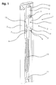
- Fig. 1 is shown in a perspective view of a rollover protection system 1. This is formed from a rollover body 2 and a drive unit 3, wherein the rollover body 2 is connected stable with a housing 4 of the drive unit 3.
- the housing 4 on its underside receptacles 7, in each of which a clamping body 8 is inserted.
- the receptacles 7 and the clamping body 8 have a groove extending in the longitudinal axis direction of the rollover body 2 and serve for the clamping reception of projections 6, which are angeklippst to the rollover body 2 and projecting in the direction of the receptacles 7.
- a triggering of the micro gas generator 9 occurs an increase in pressure inside the guide sleeve 5, which causes a sudden displacement of the coupling element 10 from the guide sleeve 5. Due to the connection of the coupling element 10 with the rollover body 2 while the rollover body 2 is displaced in the rollover position.
- the displacement movement of the rollover body 2 is limited by a arranged in the lower region of the rollover body 2 stop element 11, which engages in the rollover position with a bottom of the housing 4 of the drive unit 3 and blocks further displacement of the rollover body 2.
- a rack 12 is arranged on one of the drive unit 3 facing inside of the rollover body 2, which is biased with a biased towards the rack 12 Rack profile 13 on the housing 4 of the drive unit 3 engages.
- the rack 12 and the rack profile 13 cooperate, so that the in Longitudinal axis direction acting on the rollover body 2 in the event of rollover loads on the rack profile 13 and the housing 4 of the drive unit 3 is transmitted to the shell structure.
Landscapes
- Engineering & Computer Science (AREA)
- Mechanical Engineering (AREA)
- Cooling, Air Intake And Gas Exhaust, And Fuel Tank Arrangements In Propulsion Units (AREA)
- Lock And Its Accessories (AREA)
Description
Die Erfindung betrifft ein Überrollschutzsystem für Kraftfahrzeuge, mit
- einem aus einer Ruhelage in eine Überschlagsposition verlagerbaren Überrollkörper und
- eine den Überrollkörper im Gefahrenfall aus der Ruhelage in die Überschlagsposition verstellende Antriebseinheit mit einem eine zur Verstellung des Überrollkörpers notwendige Antriebsenergie aufweisenden Antriebsenergiespeicher.
- a movable from a rest position to a rollover position rollover body and
- a rollover body in case of danger from the rest position in the rollover position adjusting drive unit with a drive energy necessary for adjusting the rollover body drive energy storage.
Aktive Überrollschutzsysteme der Eingangs genannten Art sind in vielfältigen Ausgestaltungen aus dem Stand der Technik bekannt. Sie dienen bei Cabriolets aller Art zum Schutz der Insassen bei einem Überschlag, wobei die in der Überschlagsposition aufgestellten Überrollkörper den Insassen einen Überlebensraum bereitstellen, wenn das Fahrzeug auf den aufgestellten Überrollkörpern abrollt.Active rollover protection systems of the type mentioned above are known in a variety of configurations from the prior art. They serve in cabriolets of all kinds to protect the occupants in a rollover, wherein the rollover body set up in the rollover position provide the occupants with a survival space when the vehicle rolls on the erected rollover bodies.
Neben starr am Fahrzeug angeordneten Überrollbügeln, welche sich sowohl über die gesamte Fahrzeugbreite erstrecken, aber auch nur jeweils hinter einem Fahrzeugsitz angeordnet sein können, weisen moderne Kraftfahrzeuge vermehrt sogenannte aktive Überrollschutzsysteme auf, bei denen der Überrollkörper im Normalzustand in einer im Wesentlichen unsichtbaren Ruhelage befindlich ist und nur im Gefahrenfall, nämlich bei einem drohenden Überschlag, eine Verlagerung des Überrollkörpers in die Überschlagsposition stattfindet.In addition to rigidly arranged on the vehicle roll bars, which extend over both the entire width of the vehicle, but can also be arranged only behind a vehicle seat, modern motor vehicles increasingly called active rollover protection systems, in which the rollover body is located in the normal state in a substantially invisible rest position and only in case of danger, namely an impending rollover, a displacement of the rollover body takes place in the rollover position.
Überrollkörper, die hinter den Fahrzeugsitzen angeordnet sind und sich im Falle eines Überschlags selbsttätig aufstellen, stellen dabei eine bevorzugte Ausführungsform eines aktiven Überrollschutzsystems dar. Der Überrollkörper befindet sich dabei in der Ruhelage in Wirkverbindung mit einer Antriebseinheit, die im Bedarfsfall sensorgesteuert eine Verlagerung des Überrollkörpers aus der Ruhelage bewirkt. Zur Bereitstellung der Antriebsenergie, d. h. als Antriebsenergiespeicher der Antriebseinheit, dient dabei in der Regel ein Federsystem, wobei der Überrollkörper in der Regel in der Ruhelage durch das Federsystem vorgespannt ist und gegenüber der Vorspannung an einem Gehäuse des Überrollschutzsystems, bspw. einer Kassette, arretiert ist. Eine Auflösung der Arretierung bewirkt dann aufgrund der Federvorspannung eine unmittelbare Verstellung des Überrollkörpers in die Überschlagsposition.Rollover body, which are arranged behind the vehicle seats and set up automatically in the event of a rollover, thereby represent a preferred embodiment of an active rollover protection system. The rollover body is in the rest position in operative connection with a drive unit, the sensor-controlled, if necessary, a displacement of the rollover body the rest position causes. To provide the drive energy, ie as a drive energy storage of the drive unit, usually serves a spring system, wherein the rollover body is biased usually in the rest position by the spring system and against the bias of a housing of the Rollover protection system, eg. A cassette is locked. A resolution of the lock then causes due to the spring preload an immediate adjustment of the rollover body in the rollover position.
Die Ausgestaltung bekannter Überrollschutzsysteme macht zwingend die Verwendung eines den Überrollkörper aufnehmenden Gehäuses erforderlich, welches sowohl zur Festlegung der Position des Überrollkörpers gegenüber der Antriebseinheit als auch zur Arretierung des Überrollkörpers in der Ruhelage dient. Darüber hinaus ermöglicht erst die Verwendung eines Gehäuses für das Überrollschutzsystem dessen Handhabbarkeit und Montierbarkeit als Baueinheit, welche sich an hierfür vorgesehenen Positionen an der Rohbaustruktur des Kraftfahrzeugs einsetzen und befestigen lässt.The design of known rollover protection systems makes it absolutely necessary to use a housing receiving the rollover body, which serves both to fix the position of the rollover body relative to the drive unit and to lock the rollover body in the rest position. In addition, only the use of a housing for the rollover protection system allows its handling and assembly as a unit, which can be used and attached to designated positions on the shell structure of the motor vehicle.
Die erforderliche Verwendung eines üblicherweise kassettenartigen, d. h. den Überrollkörper und die Antriebseinheit umgreifenden Gehäuses, weist jedoch den Nachteil auf, dass derartige Überrollschutzsysteme einen erheblichen Bauraum an der Rohbaustruktur beanspruchen, an der hierfür entsprechende Aufnahmen vorgesehen werden müssen. Da diese Aufnahmen die Festigkeit der Rohbaustruktur negativ beeinflussen, ist es erforderlich, konstruktive jedoch kostenintensive Anpassungen vorzunehmen, durch die die erforderlichen Festigkeitseigenschaften erreicht werden. Darüber hinaus bedingt die Verwendung eines Gehäuses zur Bildung des Überrollschutzsystems ein erhöhtes Gewicht sowie einen höheren Fertigungsaufwand.The required use of a usually cassette-like, d. H. However, the rollover body and the drive unit encompassing housing, however, has the disadvantage that such rollover protection systems require a considerable space on the shell structure, must be provided on the corresponding recordings for this purpose. Since these images adversely affect the strength of the bodyshell structure, it is necessary to make constructive but costly adjustments, by which the required strength properties are achieved. In addition, the use of a housing to form the rollover protection system requires an increased weight and a higher production cost.
Das Dokument
Der Erfindung liegt die Aufgabe zu Grunde, ein Überrollschutzsystem der Eingangs genannten Art bereitzustellen, welches sich in einfacher Weise am Fahrzeug anordnen lässt, ein geringes Gewicht aufweist sowie einen nur geringen Bauraum beansprucht.The invention is based on the object to provide a rollover protection system of the type mentioned, which can be arranged in a simple manner on the vehicle, has a low weight and takes up only a small space.
Die Erfindung löst die Aufgabe durch ein Überrollschutzsystem mit den Merkmalen des Anspruchs 1.The invention solves the problem by a rollover protection system having the features of
Kennzeichnend für das erfindungsgemäße Überrollschutzsystem ist, dass das Gehäuse den Überrollkörper nicht umgreift.Characteristic of the rollover protection system according to the invention is that the housing does not surround the rollover body.
Wesentlich für das erfindungsgemäße Überrollschutzsystem ist die Ausgestaltung des Gehäuses der Antriebseinheit derart, dass es eine montagestabile Anordnung des Überrollkörpers an der Antriebseinheit ermöglicht. Hierdurch kann die Antriebseinheit mit dem Überrollkörper verbunden und diese relativ zueinander festgelegt werden, so dass auf weitere Bauteile, bspw. ein den Überrollkörper umgreifendes kassettenartiges Gehäuse, wie dies aus dem Stand der Technik bekannt ist, verzichtet werden kann.Essential for the rollover protection system according to the invention is the configuration of the housing of the drive unit such that it allows a mounting-stable arrangement of the rollover body on the drive unit. As a result, the drive unit can be connected to the rollover body and fixed relative to one another, so that it is possible to dispense with further components, for example a cassette-like housing enclosing the rollover body, as is known from the prior art.
Unter einer montagestabilen Verbindung wird dabei im Rahmen der Erfindung eine Verbindung von Überrollkörper und Antriebseinheit verstanden, die derart ausgebildet ist, dass die Verbindung zwischen dem Überrollkörper und der Antriebseinheit nach deren Montage aneinander während des gesamten nachfolgenden Transports sowie der Montage am Fahrzeug bestehen bleibt, jedoch im Gefahrenfall eine Verlagerung nicht blockiert.In the context of the invention, a mating-stable connection is understood to be a connection of rollover body and drive unit which is designed in such a way that the connection between the rollover body and the drive unit remains after its assembly to one another during the entire subsequent transport and assembly on the vehicle in case of danger a relocation is not blocked.
Die montagestabile Verbindung kann ferner auch dazu genutzt werden, um auch im Fahrbetrieb des Kraftfahrzeuges den Überrollkörper über die Antriebseinheit in seiner Position zu sichern, so dass auf ergänzende Lagesicherungsmaßnahmen zur Vermeidung von Relativbewegungen des Überrollkörpers gegenüber der Antriebseinheit, welche bspw. zu Klappergeräuschen führen können, verzichtet werden kann. Die montagestabile Verbindung ermöglicht es darüber hinaus im Bedarfsfall, den Überrollkörper in einfacher Weise von der Antriebseinheit zu trennen, bspw., wenn dies zu Wartungszwecken erforderlich ist.The montage-stable connection can also be used to also secure the rollover body in the driving position of the motor vehicle via the drive unit in its position, so that supplementary position assurance measures to prevent relative movement of the rollover body relative to the drive unit, which, for example, can lead to rattling noises, can be waived. The mounting stable connection also makes it possible, if necessary, to separate the rollover body in a simple manner from the drive unit, for example, if this is required for maintenance purposes.
Das erfindungsgemäße Überrollschutzsystem weist den Vorteil auf, dass es insgesamt einen nur sehr geringen, nämlich durch die Antriebseinheit und den Überrollkörper bedingten Bauraum aufweist, so dass die Rohbaustruktur insgesamt bei gleichbleibender Festigkeit wesentlich einfacher ausgeführt werden kann. Gegenüber bekannten Überrollschutzsystemen wird zudem das Gewicht und der Montageaufwand am Kraftfahrzeug reduziert. Zur Anordnung des Überrollschutzsystems muss dieses lediglich an hierfür vorgesehener Stelle der Rohbaustruktur angeordnet und anschließend die Antriebseinheit mit der Rohbaustruktur verbunden werden, wobei die Verbindung zwischen der Rohbaustruktur und der Antriebseinheit bzw. deren Gehäuse entsprechend der zu erwartenden Belastungen frei gewählt werden kann. Eine besonders komfortable Verbindung stellt dabei eine anforderungsgemäße Verschraubung der Antriebseinheit mit der Rohbaustruktur dar.The rollover protection system according to the invention has the advantage that it has a total of only a very small, namely due to the drive unit and the rollover body space, so that the shell structure can be performed much easier while maintaining the same strength. Compared to known rollover protection systems, the weight and the installation effort on the motor vehicle are also reduced. For the arrangement of the rollover protection system, this only needs to be arranged at the designated location of the bodyshell structure and then the drive unit to be connected to the bodyshell structure, the connection between the Shell structure and the drive unit or the housing can be freely selected according to the expected loads. A particularly convenient connection represents a requirement of screwing the drive unit with the bodyshell structure.
Eine Übertragung der Antriebsenergie auf den Überrollkörper kann in beliebiger Weise erfolgen, wobei bei entsprechender Ausgestaltung von Antriebseinheit und Überrollkörper auch eine unmittelbare Kraftübertragung möglich ist. Die Antriebsenergie kann jedoch auch über einen Antriebskörper erfolgen, der durch den Antriebsenergiespeicher angetrieben die Ausfahrbewegung auf den Überrollkörper überträgt. Der Antriebskörper ist dabei in der Regel Bestandteil der Antriebseinheit, er kann jedoch auch durch ein mit dem Überrollkörper verbundenes und mit der Antriebseinheit in Eingriff befindliches Bauteil gebildet sein.A transmission of the drive energy to the rollover body can be done in any way, with an appropriate design of the drive unit and rollover body and an immediate power transmission is possible. However, the drive energy can also be effected via a drive body which, driven by the drive energy store, transmits the extension movement to the rollover body. The drive body is usually part of the drive unit, but it may also be formed by a component connected to the rollover body and with the drive unit in engagement.
Die Ausgestaltung der montagestabilen Verbindung zwischen dem Überrollkörper und dem Gehäuse der Antriebseinheit kann grundsätzlich in beliebiger Weise erfolgen, sofern die gewählte Ausgestaltung gewährleistet, dass der Überrollkörper relativ gegenüber der Antriebseinheit festgelegt ist und im Gefahrenfall die Verlagerung in die Überschlagsposition zuverlässig erfolgen kann. So kann gemäß einer möglichen Ausgestaltung der Erfindung das Gehäuse der Antriebseinheit bspw. eine an den Überrollkörper angepasste Gestalt aufweisen, die eine kraftschlüssige Verbindung mit dem Überrollkörper oder Abschnitten des Überrollkörpers erlaubt.The design of the stable assembly connection between the rollover body and the housing of the drive unit can in principle be carried out in any way, provided that the selected configuration ensures that the rollover body is set relative to the drive unit and in the event of danger, the relocation can be done reliably in the rollover position. Thus, according to a possible embodiment of the invention, the housing of the drive unit, for example, have a shape adapted to the rollover body, which allows a frictional connection with the rollover body or portions of the rollover body.
Gemäß einer vorteilhaften Weiterbildung der Erfindung ist der Überrollkörper jedoch über ein sich in einem Bereich zwischen dem Gehäuse der Antriebseinheit und dem Überrollkörper erstreckendes Verbindungsmittel montagestabil mit der Antriebseinheit verbunden. Gemäß dieser Ausgestaltung der Erfindung verläuft das Verbindungsmittel zwischen dem Überrollkörper einerseits und dem Gehäuse der Antriebseinheit andererseits. Das Verbindungsmittel sichert dabei die Lage des Überrollkörpers relativ zur Antriebseinheit und gewährleistet gleichzeitig, dass im Falle eines Überschlags der Überrollkörper zuverlässig in die Überschlagsposition verstellt werden kann. Die Ausgestaltung der Verbindungsmittel ist dabei grundsätzlich, wie auch deren Ausrichtung, frei wählbar, wobei besonders bevorzugt sich das Verbindungsmittel zwischen einander gegenüberliegenden Abschnitten des Gehäuses der Antriebseinheit einerseits und dem Überrollkörper andererseits erstreckt, wodurch eine besonders kompakte Ausgestaltung des Überrollschutzsystems erreicht werden kann.According to an advantageous development of the invention, however, the rollover body is connected to the drive unit so as to be stable in assembly, via a connecting means extending in a region between the housing of the drive unit and the rollover body. According to this embodiment of the invention, the connecting means extends between the rollover body on the one hand and the housing of the drive unit on the other. The connecting means secures the position of the rollover body relative to the drive unit and at the same time ensures that in case of a rollover the rollover body can be reliably adjusted to the rollover position. The design of the connecting means is basically, as well as their orientation, freely selectable, with particularly preferred, the connecting means between each other Sections of the housing of the drive unit on the one hand and the rollover body on the other hand extends, whereby a particularly compact design of the rollover protection system can be achieved.
Grundsätzlich besteht die Möglichkeit, den Überrollkörper im Wesentlichen über die gesamte Länge des Gehäuses der Antriebseinheit - in Längsachsenrichtung des Überrollkörpers betrachtet - mit dem Überrollkörper zu verbinden. Nach einer besonders vorteilhaften Ausgestaltung der Erfindung erstrecken sich die Verbindungsmittel jedoch nur über einen Teilbereich des Überrollkörpers und/oder der Antriebseinheit bzw. des Gehäuses der Antriebseinheit. Eine entsprechende Ausgestaltung, die zum einen gewährleistet, dass der Überrollkörper montagestabil an der Antriebseinheit angeordnet ist und zum anderen eine zuverlässige Verlagerung des Überrollkörpers in die Überschlagsposition zulässt, ermöglicht eine besonders kompakte sowie materialsparende Bauweise.Basically, it is possible to connect the rollover body substantially over the entire length of the housing of the drive unit - viewed in the longitudinal axis direction of the rollover body - with the rollover body. According to a particularly advantageous embodiment of the invention, however, the connecting means extend only over a portion of the rollover body and / or the drive unit or the housing of the drive unit. A corresponding configuration, which on the one hand ensures that the rollover body is arranged so as to be stable on the drive unit and on the other hand permits a reliable displacement of the rollover body into the rollover position, permits a particularly compact and material-saving design.
Wie bereits zuvor ausgeführt, ist die Ausgestaltung der Verbindungsmittel frei wählbar, sofern die vorgenannten Eigenschaften einer montagestabilen Verbindung erzielt werden. Nach einer Weiterbildung der Erfindung ist das Gehäuse der Antriebseinheit und/oder der Überrollkörper jedoch zur Aufnahme von einem an dem Überrollkörper und/oder dem Gehäuse der Antriebseinheit angeordneten Vorsprung ausgebildet. Der Vorsprung dient dabei gemeinsam mit einer entsprechenden Ausgestaltung an der Antriebseinheit oder dem Überrollkörper zur Aufnahme des Vorsprungs als Verbindungsmittel zur Festlegung des Überrollkörpers an der Antriebseinheit. Der Vorsprung kann dabei integraler Bestandteil der Antriebseinheit oder des Überrollkörpers sein oder auch durch geeignete Maßnahmen an dem Überrollkörper oder der Antriebseinheit angeordnet werden. Ein Vorsprung lässt sich besonders einfach ausgestalten und ermöglicht über seine Form überdies eine Festlegung des Abstands des Überrollkörpers zur Antriebseinheit. Somit kann in besonders einfacher und kostengünstiger Weise eine Ausrichtung des Überrollkörpers gegenüber dem Gehäuse der Antriebseinheit bzw. der Antriebseinheit erfolgen, wobei im Falle bspw. anklippsbarer Vorsprünge an der Antriebseinheit oder dem Überrollkörper eine einfache Justierbarkeit des Überrollkörpers gegenüber der Antriebseinheit möglich ist.As already stated above, the design of the connecting means is freely selectable, provided that the aforementioned properties of a mating-stable connection are achieved. According to a development of the invention, however, the housing of the drive unit and / or the rollover body is designed to receive a projection arranged on the rollover body and / or the housing of the drive unit. The projection serves together with a corresponding configuration on the drive unit or the rollover body for receiving the projection as a connecting means for fixing the rollover body to the drive unit. The projection can be an integral part of the drive unit or the rollover body or can be arranged by suitable measures on the rollover body or the drive unit. A projection can be made particularly simple and also allows its form a determination of the distance of the rollover body to the drive unit. Thus, in a particularly simple and cost-effective manner, an alignment of the rollover body relative to the housing of the drive unit or the drive unit, wherein in the case, for example. Anklippsbarer projections on the drive unit or the rollover body a simple adjustability of the rollover body relative to the drive unit is possible.
Nach einer besonders vorteilhaften Ausgestaltung der Erfindung ist der Vorsprung in einer in Verstellrichtung des Überrollkörpers längskanalisierten, sich über einen Teilbereich des Gehäuses der Antriebseinheit erstreckenden Aufnahme angeordnet. Bei einer entsprechenden Ausgestaltung der Erfindung ist der Vorsprung, ggf. unter Zuhilfenahme geeigneter Klemmmittel, kraft-, form- und/oder stoffschlüssig in der Aufnahme angeordnet, um eine relative Festlegung des Überrollkörpers an der Antriebseinheit zu gewährleisten. Die Längskanalisierung, welche in Verstellrichtung des Überrollkörpers verläuft, weist dabei den Vorteil auf, dass durch diese eine Führung des Überrollkörpers gegenüber der Antriebseinheit im Bereich des Zusammenwirkens von Vorsprung und Aufnahme erfolgt. Insofern wird durch eine entsprechende Ausgestaltung zum einen eine zuverlässige Festlegung des Überrollkörpers an der Antriebseinheit gleichzeitig aber auch eine sichere sowie gerichtete Verlagerungsmöglichkeit im Gefahrenfall gewährleistet.According to a particularly advantageous embodiment of the invention, the projection in a longitudinally channeled in the adjustment of the rollover body, arranged over a portion of the housing of the drive unit receiving. In a corresponding embodiment of the invention, the projection, optionally with the aid of suitable clamping means, force, form and / or cohesively disposed in the receptacle to ensure a relative fixing of the rollover body to the drive unit. The longitudinal channelization, which extends in the adjustment direction of the rollover body, has the advantage that this is done by a guide of the rollover body relative to the drive unit in the region of the interaction of projection and recording. In this respect, a reliable definition of the rollover body on the drive unit at the same time as well as a safe and directional displacement possibility in the event of danger is ensured by an appropriate design.
Gemäß einer weiteren Ausgestaltung der Erfindung weist die Antriebseinheit eine Führungshülse auf, die zur Aufnahme eines mit dem Überrollkörper verbundenen Kopplungselements ausgebildet ist. Eine freie Verschiebbarkeit des Kopplungselements in der sich in Verstellrichtung erstreckenden Führungshülse gewährleistet zuverlässig, dass im Gefahrenfall eine Verlagerung des Überrollkörpers in die Überschlagsposition erfolgt. Die Führungshülse kann dabei zusätzlich zu weiteren Verbindungsmitteln eingesetzt werden, so dass insgesamt eine montagestabile Verbindung hergestellt werden kann, bei der auch die Führungshülse als Verbindungsmittel dient. Gemäß einer besonders vorteilhaften Ausgestaltung der Erfindung ist ein Antriebskörper vorgesehen, der in der sich über einen Teilbereich des Überrollkörpers erstreckenden Führungshülse angeordnet ist, so dass im Falle einer Auslösung der Antriebseinheit der Antriebskörper angetrieben wird und unmittelbar seine Bewegungsenergie innerhalb der Führungshülse auf das Kopplungselement überträgt. Im Falle der Verwendung eines an dem Überrollkörper angeordneten Kopplungselements, welches innerhalb der Führungshülse gelagert ist, kann, bei einer entsprechenden Auswahl des Antriebsenergiespeichers, auch auf einen separaten Antriebskörper verzichtet werden, so dass die Antriebsenergie unmittelbar auf das Kopplungselement wirkt.According to a further embodiment of the invention, the drive unit has a guide sleeve which is designed to receive a coupling element connected to the rollover body. A free displaceability of the coupling element in the guide sleeve extending in the adjustment direction reliably ensures that, in the event of danger, the rollover body is displaced into the rollover position. The guide sleeve can be used in addition to other connecting means, so that a total of a montage-stable connection can be made, in which the guide sleeve serves as a connecting means. According to a particularly advantageous embodiment of the invention, a drive body is provided, which is arranged in the over a portion of the rollover body extending guide sleeve, so that in case of release of the drive unit, the drive body is driven and immediately transmits its kinetic energy within the guide sleeve on the coupling element. In the case of using a arranged on the rollover coupling element which is mounted within the guide sleeve, can be dispensed with a corresponding selection of the drive energy storage, on a separate drive body, so that the drive energy acts directly on the coupling element.
Nach einer weiteren Ausgestaltung der Erfindung sind an dem Überrollkörper und/oder der Antriebseinheit Anschlagmittel zur Begrenzung der Ausfahrbewegung des Überrollkörpers angeordnet. Diese Ausgestaltung der Erfindung, wonach die maximale Ausfahrposition durch ein Zusammenwirken des Überrollkörpers mit der Antriebseinheit über Anschlagmittel bestimmt ist, ermöglicht es, auf separate Vorrichtungen zur Begrenzung der Ausfahrbewegung an der Rohbaustruktur zu verzichten. Das derart ausgebildete Überrollschutzsystem lässt sich somit in besonders einfacher Weise an der Rohbaustruktur anordnen, wobei lediglich eine Verbindung der Antriebseinheit mit der Rohbaustruktur, bspw. eine Verschraubung, erforderlich ist.According to a further embodiment of the invention are on the rollover body and / or the drive unit stop means for limiting the extension movement of the rollover body arranged. This embodiment of the invention, according to which the maximum extension position is determined by an interaction of the rollover body with the drive unit via stop means, makes it possible to dispense with separate devices for limiting the extension movement of the shell structure. The thus formed rollover protection system can thus be arranged in a particularly simple manner to the shell structure, with only a connection of the drive unit with the shell structure, for example. A gland is required.
Zur Gewährleistung der Funktion des Überrollschutzsystems ist es grundsätzlich erforderlich, dass der Überrollkörper in der Überschlagsposition gegen eine Rückverlagerung gesichert ist, um die beim Überschlag auf den Überrollkörper wirkenden Lasten aufnehmen zu können. Eine hierfür erforderliche Verriegelung des Überrollkörpers kann bspw. an der Rohbaustruktur vorgesehen sein. Besonders vorteilhafter Weise sind jedoch an der Antriebseinheit Verriegelungsmittel zur Arretierung des Überrollkörpers in der Überschlagsposition ausgebildet. Eine entsprechende Ausgestaltung ermöglicht es bei einer entsprechend laststabilen Verbindung der Antriebseinheit bzw. dem Gehäuse der Antriebseinheit mit der Rohbaustruktur, auf eine Anpassung der Rohbaustruktur zu verzichten. Als Verriegelungsmittel können dabei grundsätzlich alle Ausgestaltungen verwendet werden, welche eine Rückverlagerung des Überrollkörpers in Richtung der Ruhelage verhindern. Besonders vorteilhafter Weise kann dies über eine an dem Überrollkörper angeordnete Zahnstange erfolgen, welche in der Überschlagsposition mit einem an der Antriebseinheit angeordneten Zahnstangenprofil in Eingriff gelangt.To ensure the function of the rollover protection system, it is generally necessary that the rollover body is secured in the rollover position against a return displacement in order to accommodate the forces acting on the rollover body during the rollover can. A required locking of the rollover body may, for example, be provided on the shell structure. However, particularly advantageously, locking means for locking the rollover body in the rollover position are formed on the drive unit. A corresponding configuration makes it possible to dispense with an adaptation of the bodyshell structure with a correspondingly load-stable connection of the drive unit or the housing of the drive unit with the bodyshell structure. In principle, all embodiments which prevent a rearward displacement of the rollover body in the direction of the rest position can be used as the locking means. Particularly advantageously, this can take place via a toothed rod arranged on the rollover body, which engages in the rollover position with a toothed rack profile arranged on the drive unit.
Gemäß einer vorteilhaften Weiterbildung der Erfindung sind der Überrollkörpers und die Antriebseinheit derart miteinander in Eingriff, dass der Überrollkörper in der Ruhelage unbelastet durch die Antriebseinheit ist, so dass eine Anordnung des Überrollkörpers an der Antriebseinheit in besonders einfacher Weise erfolgen kann. Der Überrollkörper muss nicht entgegen einer Vorspannkraft, bspw. einer Federvorspannung, in eine Ruhelage verschoben und bspw. an der Antriebseinheit oder einer anderen Baugruppe, wie z. B. einem gemeinsamen Gehäuse, arretiert werden. Eine vorspannungsfreie Verbindung der Antriebseinheit mit dem Überrollkörper resultiert dabei im Wesentlichen daraus, dass die Antriebsenergie innerhalb der Antriebseinheit im Antriebsenergiespeicher festgelegt ist. Eine Freigabe der Antriebsenergie, durch die diese auf den Überrollkörper übertragen wird, erfolgt erst, wenn der Gefahrenfall eintritt, d. h. ein Überschlag droht bzw. stattfindet. Erst zu diesem Zeitpunkt erfolgt eine Kraftbeaufschlagung des Überrollkörpers durch die Antriebseinheit, wodurch der Überrollkörper in die Überschlagsposition verlagert wird. Bis zum Gefahrenfall ist der Überrollkörper jedoch unbelastet durch die Antriebseinheit, was eine besonders einfache Montage des Überrollkörpers an der Antriebseinheit ermöglicht.According to an advantageous embodiment of the invention, the rollover body and the drive unit are engaged with each other such that the rollover body in the rest position is unloaded by the drive unit, so that an arrangement of the rollover body on the drive unit can be done in a particularly simple manner. The rollover body does not have to be displaced against a biasing force, for example, a spring preload, into a rest position and, for example, on the drive unit or another assembly, such as. B. a common housing, are locked. A bias-free connection of the drive unit with the rollover body results essentially from the fact that the drive energy is set within the drive unit in the drive energy storage. A release of the drive energy, by which this on the rollover body is transmitted, takes place only when the danger occurs, ie a rollover threatens or takes place. Only at this time is a force applied to the rollover body by the drive unit, whereby the rollover body is moved to the rollover position. However, up to the danger of the rollover body is unloaded by the drive unit, which allows a particularly simple installation of the rollover body on the drive unit.
Die Bereitstellung der Antriebsenergie, d. h. des Antriebsenergiespeichers, kann grundsätzlich in beliebiger Weise ausgeführt werden. So ist gemäß einer möglichen Ausgestaltung vorgesehen, dass innerhalb der Antriebseinheit eine Federvorspannung vorliegt, welche besonders bevorzugt gegenüber dem Gehäuse der Antriebseinheit gesichert ist, um eine vorzugsweise vorspannungsfreie Anordnung des Überrollkörpers zu ermöglichen. Im Gefahrenfall wird durch eine Auflösung der Verriegelung die Vorspannung freigegeben und auf den Überrollkörper, ggf. über einen Antriebskörper, übertragen.The provision of drive energy, d. H. the drive energy storage, can basically be performed in any way. Thus, according to a possible embodiment, provision is made for a spring preload to be present within the drive unit, which is particularly preferably secured relative to the housing of the drive unit in order to allow a preferably pretension-free arrangement of the rollover body. In case of danger, the bias is released by a resolution of the locking and transmitted to the rollover body, possibly via a drive body.
Nach einer besonders vorteilhaften Ausgestaltung der Erfindung ist der Antriebsenergiespeicher jedoch durch einen Gasgenerator, insbesondere Mikrogasgenerator, gebildet. Zur Verwendung eines entsprechenden Gasgenerators weist das Gehäuse der Antriebseinheit einen Druckraum auf, in dem sich durch Aktivierung des Gasgenerators schlagartig ein Überdruck ausbildet, welcher zur Verlagerung des Überrollkörpers genutzt wird. Hierzu kann bspw. das vorzugsweise vorgesehene Kopplungselement des Überrollkörpers in den Druckraum hineinragen, so dass aufgrund der Druckerhöhung das Kopplungselement aus dem Druckraum herausbefördert wird und dabei den Überrollkörper in die Überschlagsposition verlagert.According to a particularly advantageous embodiment of the invention, however, the drive energy storage is formed by a gas generator, in particular micro gas generator. To use a corresponding gas generator, the housing of the drive unit to a pressure chamber in which abruptly forms an overpressure by activation of the gas generator, which is used to displace the rollover body. For this purpose, for example, the preferably provided coupling element of the rollover body protrude into the pressure chamber, so that due to the pressure increase, the coupling element is conveyed out of the pressure chamber and thereby displaces the rollover body in the rollover position.
Die der Erfindung zu Grunde liegende Aufgabe wird ferner durch eine Antriebseinheit für ein Überrollschutzsystem zur Verlagerung eines Überrollkörpers aus einer Ruhelage in eine Überschlagsposition, insbesondere zur Verwendung in einem Überrollschutzsystem wie vorstehend beschrieben, dadurch gelöst, dass ein Gehäuse der Antriebseinheit zur montagestabilen Anordnung des Überrollkörpers ausgebildet ist.The object underlying the invention is further achieved by a drive unit for a rollover protection system for shifting a rollover body from a rest position to a rollover position, in particular for use in a rollover protection system as described above, characterized in that a housing of the drive unit for mounting-stable arrangement of the rollover body is.
Wesentlich für die erfindungsgemäße Antriebseinheit ist dabei, dass das Gehäuse der Antriebseinheit auf den Überrollkörper abgestimmt ist und dessen Anordnung in montagestabiler Weise an dem Gehäuse ermöglicht. Eine montagestabile Verbindung zwischen der Antriebseinheit und dem Überrollkörper zur Bildung eines Überrollschutzsystems besteht dabei dann, wenn gewährleistet ist, dass die Verbindung zwischen der Antriebseinheit und dem Überrollkörper auch während der Montage des Überrollschutzsystems am Kraftfahrzeug bestehen bleibt, eine Verstellung im Gefahrenfall jedoch nicht behindert. Vorzugsweise ist die montagestabile Verbindung ferner dergestalt, dass Relativbewegungen im Normalbetrieb des Kraftfahrzeugs und damit einhergehende Klappergeräusche vermieden werden. Eine Anbindung des Überrollschutzsystems am Kraftfahrzeug erfolgt über eine Festlegung, bspw. Verschraubung, der Antriebseinheit an hierfür vorgesehener Stelle an der Rohbaustruktur.Essential for the drive unit according to the invention is that the housing of the drive unit is tuned to the rollover body and its arrangement in stable mounting Way on the housing allows. An assembly-stable connection between the drive unit and the rollover body to form a rollover protection system consists in this case, if it is ensured that the connection between the drive unit and the rollover body remains during assembly of the rollover protection system on the motor vehicle, but does not hinder adjustment in case of danger. Preferably, the mounting stable connection is further such that relative movements during normal operation of the motor vehicle and associated rattling noises are avoided. A connection of the rollover protection system on the motor vehicle via a determination, for example. Screw, the drive unit at this point provided on the shell structure.
Die Verwendung einer zur montagestabilen Anordnung ausgebildeten Antriebseinheit ermöglicht es, auf ein anderenfalls erforderliches Gehäuse zur Aufnahme der Antriebseinheit und des Überrollkörpers zur Bildung eines Überrollschutzsystems zu verzichten. Das Überrollschutzsystem kann somit gehäuse- bzw. kassettenfrei ausgebildet werden, so dass ein unter Verwendung der erfindungsgemäßen Antriebseinheit hergestelltes Überrollschutzsystem gegenüber bekannten Überrollschutzsystemen einen wesentlich geringeren Bauraum sowie ein geringeres Eigengewicht aufweist.The use of a drive unit designed for assembly-stable arrangement makes it possible to dispense with an otherwise required housing for receiving the drive unit and the rollover body to form a rollover protection system. The rollover protection system can thus be formed housing or cassette-free, so that a manufactured using the drive unit according to the invention rollover protection system over known rollover protection systems has a much smaller space and a lower weight.
Aufgrund des geringen Bauraums ergeben sich Vorteile bei der Ausgestaltung einer Rohbaustruktur des Kraftfahrzeuges, welche in geringerem Maße an das Überrollschutzsystem angepasst werden muss, so dass sich eine erhöhte Festigkeit ergibt. Wesentlich für die Möglichkeit, auf ein Gehäuse zur Aufnahme des Überrollkörpers und der Antriebseinheit verzichten zu können, ist dabei die montagestabile Verbindung, durch die der Überrollkörper auch ohne ein zusätzliches Gehäuse relativ gegenüber der Antriebseinheit festgelegt ist, wobei die montagestabile Anordnung dergestalt ist, dass im Gefahrenfall die Antriebseinheit den Überrollkörper störungsfrei in die Überschlagsposition verlagern kann.Due to the small space, there are advantages in the design of a bodyshell structure of the motor vehicle, which must be adapted to a lesser extent to the rollover protection system, so that there is an increased strength. Essential for the possibility of being able to dispense with a housing for receiving the rollover body and the drive unit, is the mounts stable connection through which the rollover body is set without an additional housing relative to the drive unit, wherein the assembly-stable arrangement is such that in In the event of danger, the drive unit can shift the rollover body without interference into the rollover position.
Nach einer besonders vorteilhaften Ausgestaltung der Antriebseinheit ist vorgesehen, dass das Gehäuse der Antriebseinheit zur Anbringung an einer Rohbaustruktur eines Kraftfahrzeugs ausgebildet ist. Gemäß dieser Weiterbildung kann auf ergänzende Verbindungsmittel zur Anordnung der Antriebseinheit bzw. des aus Antriebseinheit und Überrollkörper gebildeten Überrollschutzsystems verzichtet werden. Die Verbindung erfolgt allein über eine direkte Kopplung der Antriebseinheit mit der Rohbaustruktur des Kraftfahrzeugs, wobei das Gehäuse der Antriebseinheit, bspw. mit der Rohbaustruktur, vernietet oder verschraubt wird.According to a particularly advantageous embodiment of the drive unit is provided that the housing of the drive unit is designed for attachment to a shell structure of a motor vehicle. According to this development, complementary connecting means for arranging the drive unit or the drive unit and can be used Roll body formed rollover protection system can be dispensed with. The connection is made solely via a direct coupling of the drive unit with the shell structure of the motor vehicle, wherein the housing of the drive unit, for example. With the shell structure, riveted or screwed.
Gemäß einer besonders vorteilhaften Ausgestaltung der Erfindung ist ferner vorgesehen, dass an dem Gehäuse der Antriebseinheit Verriegelungsmittel zur Arretierung des Überrollkörpers in der Überschlagsposition ausgebildet sind. Diese Ausgestaltung der Erfindung, wonach die Antriebseinheit neben der Möglichkeit zur montagestabilen Anordnung ferner noch eine Arretierung des Überrollkörpers in der Überschlagsposition erlaubt, ermöglicht es, im Bereich der Rohbaustruktur auf entsprechende Ausgestaltungen zur Festlegung des Überrollkörpers in der Überschlagsposition zu verzichten. Im Überschlagsfall auf den Überrollkörper wirkende Kräfte werden in Verstellrichtung des Überrollkörpers über das Gehäuse der Antriebseinheit und dessen bestehende Verbindung mit der Rohbaustruktur übertragen, so dass auf ergänzende Maßnahmen an der Rohbaustruktur verzichtet werden kann.According to a particularly advantageous embodiment of the invention is further provided that are formed on the housing of the drive unit locking means for locking the rollover body in the rollover position. This embodiment of the invention, according to which the drive unit in addition to the possibility for assembly-stable arrangement also still allows locking of the rollover body in the rollover position, makes it possible to dispense in the shell structure on appropriate configurations for fixing the rollover body in the rollover position. In rollover case acting on the rollover body forces are transmitted in the adjustment of the rollover body on the housing of the drive unit and its existing connection with the shell structure, so that can be dispensed with complementary measures to the shell structure.
Die erfindungsgemäße Antriebseinheit weist einen Antriebsenergiespeicher zur Verlagerung des Überrollkörpers in die Überschlagsposition auf. Eine Übertragung der Antriebsenergie auf den Überrollkörper kann dabei in beliebiger Weise erfolgen, wobei auch eine unmittelbare Übertragung der Antriebsenergie auf geeignete Bauteile des Überrollkörpers bei entsprechender Anordnung an dem Gehäuse der Antriebseinheit möglich ist. Nach einer besonders vorteilhaften Ausgestaltung der Erfindung weist die Antriebseinheit jedoch einen mit dem Überrollkörper in Eingriff bringbaren, diesen in der Ruhelage nicht belastenden und durch einen Antriebsenergiespeicher antreibbaren Antriebskörper auf. Gemäß dieser Ausgestaltung der Erfindung weist die Antriebseinheit einen separaten Antriebskörper auf, welcher erst im Gefahrenfall aufgrund der Energie des Antriebsenergiespeichers verlagert wird. In der Ruhelage ist der Antriebskörper an der Antriebseinheit bzw. dem Gehäuse der Antriebseinheit festgelegt, so dass im Falle einer Anordnung des Überrollkörpers an der Antriebseinheit dieser unbelastet ist. Diese Ausgestaltung der Antriebseinheit ermöglicht eine einfache und kostengünstige und vor allem verspannungsfreie Montage des Überrollkörpers an der Antriebseinheit.The drive unit according to the invention has a drive energy storage for the displacement of the rollover body in the rollover position. A transmission of the drive energy to the rollover body can be done in any way, with a direct transmission of the drive energy to suitable components of the rollover body with a corresponding arrangement on the housing of the drive unit is possible. According to a particularly advantageous embodiment of the invention, however, the drive unit has a with the rollover body engageable, this in the rest position not burdening and driven by a drive energy storage drive body. According to this embodiment of the invention, the drive unit has a separate drive body, which is displaced only in case of danger due to the energy of the drive energy storage. In the rest position of the drive body is fixed to the drive unit or the housing of the drive unit, so that in the case of an arrangement of the rollover body on the drive unit, this is unloaded. This embodiment of the drive unit allows a simple and inexpensive and above all tension-free mounting of the rollover body on the drive unit.
Der Antriebsenergiespeicher kann dabei in beliebiger Weise ausgebildet sein. So ist bspw. die Verwendung eines Gasgenerators oder einer Federvorspannung denkbar, wobei im Falle der Verwendung einer Federvorspannung vorzugsweise ein durch die Federvorspannung vorgespannter Antriebskörper im Gehäuse festgelegt ist.The drive energy storage can be designed in any way. Thus, for example, the use of a gas generator or a spring preload is conceivable, wherein in the case of using a spring preload preferably a biased by the spring bias drive body is fixed in the housing.
Die Erfindung löst die eingangs genannte Aufgabe ferner durch ein Überrollschutzsystem für Kraftfahrzeuge, das dadurch gekennzeichnet ist, dass ein Gehäuse der Antriebseinheit zur montagestabilen Anordnung des Überrollkörpers ausgebildet ist, wobei im Übrigen die Verbindung von Überrollkörper und Antriebseinheit ohne ein den Überrollkörper umgreifendes Gehäuse ausgebildet ist, so dass das Überrollschutzsystem aufgrund des Verzichts des Gehäuses besonders klein und kostengünstig sowie nur einen geringen Bauraum beanspruchend ausgebildet ist.The invention solves the above-mentioned object further by a rollover protection system for motor vehicles, which is characterized in that a housing of the drive unit is designed for assembly-stable arrangement of the rollover body, wherein the connection of rollover body and drive unit is otherwise formed without the rollover body enclosing housing, so that the rollover protection system is designed to be particularly small and inexpensive and only a small space consuming due to the waiver of the housing.
Ein Ausführungsbeispiel der Erfindung wird nachstehend mit Bezug auf die Zeichnungen näher erläutert. In den Zeichnungen zeigen:
- Fig. 1
- eine perspektivische Ansicht eines aus einer Antriebseinheit und einem Überrollkörper gebildeten Überrollschutzsystems und
- Fig. 2
- eine vergrößerte Darstellung eines oberen Bereichs des Überrollschutzsystems von
Fig. 1 .
- Fig. 1
- a perspective view of a rollover protection system formed from a drive unit and a rollover body and
- Fig. 2
- an enlarged view of an upper portion of the rollover protection system of
Fig. 1 ,
In
Zur montagestabilen Verbindung weist das Gehäuse 4 an seiner Unterseite Aufnahmen 7 auf, in die jeweils ein Klemmkörper 8 eingesetzt ist. Die Aufnahmen 7 und die Klemmkörper 8 weisen eine sich in Längsachsenrichtung des Überrollkörpers 2 erstreckende Vertiefung auf und dienen zur klemmenden Aufnahme von Vorsprüngen 6, welche an den Überrollkörper 2 angeklippst sind und in Richtung auf die Aufnahmen 7 vorstehen.For assembly-stable connection, the
Darüber hinaus ist an dem Gehäuse 4 der Antriebseinheit 3 eine sich in Längsachsenrichtung des Überrollkörpers 2 erstreckende Führungshülse 5 angeordnet, in welcher in der Ruhelage ein mit dem Überrollkörper 2 verbundenes Kopplungselement 10 angeordnet ist. Über die Verbindung des Kopplungselements 10 mit der Führungshülse 5 sowie über die Vorsprünge 6 und die Aufnahmen 7 ist der Überrollkörper 2 in der in
Zur Montage des Überrollschutzsystems 1 an einer Rohbaustruktur eines Kraftfahrzeuges ist es lediglich erforderlich, die Antriebseinheit 3 über Befestigungsöffnungen 14 an dem Gehäuse 4 mit der Rohbaustruktur zu verschrauben.For mounting the
Eine Verlagerung des Überrollkörpers 2 aus der in
Die Verlagerungsbewegung des Überrollkörpers 2 wird durch ein im unteren Bereich des Überrollkörpers 2 angeordnetes Anschlagelement 11 begrenzt, welches in der Überschlagsposition mit einer Unterseite des Gehäuses 4 der Antriebseinheit 3 in Eingriff gelangt und eine Weiterverlagerung des Überrollkörpers 2 blockiert. Zur Sicherung der Überschlagsposition des Überrollkörpers 2, um zu verhindern, dass der Überrollkörper 2 in Richtung auf die Ruhelage zurückverlagert wird, ist an einer der Antriebseinheit 3 zugewandten Innenseite des Überrollkörpers 2 eine Zahnstange 12 angeordnet, welche mit einem in Richtung auf die Zahnstange 12 vorgespannten Zahnstangenprofil 13 an dem Gehäuse 4 der Antriebseinheit 3 in Eingriff gelangt. In der Überschlagsposition wirken die Zahnstange 12 sowie das Zahnstangenprofil 13 zusammen, so dass die in Längsachsenrichtung auf den Überrollkörper 2 im Überschlagsfall wirkenden Lasten über das Zahnstangenprofil 13 und das Gehäuse 4 der Antriebseinheit 3 auf die Rohbaustruktur übertragen wird.The displacement movement of the
Claims (10)
- A rollover protection system (1) for motor vehicles, with- a rollover body (2) displaceable from a rest position into a rollover position and- a drive unit (3), moving the rollover body in the event of a hazardous situation out of the rest position into the rollover position, with a drive energy store (9) having a drive energy necessary for the movement of the rollover body, whereinthe rollover body (2) is connected to the drive unit (3) via a housing (4) of the drive unit (3) designed for the securely mounted arrangement of the rollover body (2),
characterized in that the housing (4) does not surround the rollover body. - The rollover protection system according to claim 1, characterized in that the rollover body (2) is connected to the drive unit (3) in a securely mounted manner via a connection means extending in a region between the housing (4) of the drive unit (3) and the rollover body.
- The rollover protection system according to claim 1 or 2, characterized in that the connection means extend over a partial region of the rollover body (2) and/or the drive unit (3).
- The rollover protection system according to one of the preceding claims, characterized in that the housing (4) of the drive unit (3) and/or the rollover body (2) is designed for accommodating a projection (6) arranged on the rollover body (2) and/or the housing (4) of the drive unit (3).
- The rollover protection system according to claim 4, characterized in that the projection (6) is arranged in a receptacle (7) extending longitudinally channeled in the movement direction of the rollover body (2) over a partial region of the housing (4) of the drive unit (3).
- The rollover protection system according to one of the preceding claims, characterized in that the drive body is arranged in a guide sleeve (5) extending over a partial region of the rollover body (2), wherein the guide sleeve (5) is designed for accommodating a coupling element (10) connected to the rollover body (2).
- The rollover protection system according to one of the preceding claims, characterized in that stop means (11) are arranged on the rollover body (2) and/or the drive unit (3) for limiting the extension movement of the rollover body (2).
- The rollover protection system according to one of the preceding claims, characterized in that locking means (13) are formed on the drive unit (3) for locking the rollover body (2) in the rollover position.
- The rollover protection system according to one of the preceding claims, characterized in that the rollover body (2) is connected in a securely mounted manner to the housing (4) of the drive unit (3) without being pretensioned for displacement thereof.
- The rollover protection system according to one of the preceding claims, characterized in that the drive energy store is formed by a gas generator, in particular a micro gas generator (9).
Priority Applications (1)
| Application Number | Priority Date | Filing Date | Title |
|---|---|---|---|
| EP20110152077 EP2420413B1 (en) | 2011-01-25 | 2011-01-25 | Rollover protection for motor vehicles |
Applications Claiming Priority (1)
| Application Number | Priority Date | Filing Date | Title |
|---|---|---|---|
| EP20110152077 EP2420413B1 (en) | 2011-01-25 | 2011-01-25 | Rollover protection for motor vehicles |
Publications (2)
| Publication Number | Publication Date |
|---|---|
| EP2420413A1 EP2420413A1 (en) | 2012-02-22 |
| EP2420413B1 true EP2420413B1 (en) | 2014-04-23 |
Family
ID=44064965
Family Applications (1)
| Application Number | Title | Priority Date | Filing Date |
|---|---|---|---|
| EP20110152077 Active EP2420413B1 (en) | 2011-01-25 | 2011-01-25 | Rollover protection for motor vehicles |
Country Status (1)
| Country | Link |
|---|---|
| EP (1) | EP2420413B1 (en) |
Families Citing this family (2)
| Publication number | Priority date | Publication date | Assignee | Title |
|---|---|---|---|---|
| DE102013112266A1 (en) | 2013-11-07 | 2015-05-07 | Jakob Löwen | Rollover protection system for motor vehicles |
| CN117184007A (en) * | 2023-10-20 | 2023-12-08 | 浙江极氪智能科技有限公司 | vehicle |
Family Cites Families (3)
| Publication number | Priority date | Publication date | Assignee | Title |
|---|---|---|---|---|
| DE19501522A1 (en) * | 1994-01-29 | 1995-08-03 | Volkswagen Ag | Roll-over protection for convertible motor vehicle |
| EP1277647A1 (en) * | 2001-07-18 | 2003-01-22 | Mazda Motor Corporation | Body structure for convertible car |
| ES2225703T3 (en) * | 2001-08-31 | 2005-03-16 | Ise Innomotive Systems Europe Gmbh | ANTI-SPORTS PROTECTION SYSTEM FOR AUTOMOBILE VEHICLES THAT INCLUDES A PART OF THEORETICAL DEFORMATION. |
-
2011
- 2011-01-25 EP EP20110152077 patent/EP2420413B1/en active Active
Also Published As
| Publication number | Publication date |
|---|---|
| EP2420413A1 (en) | 2012-02-22 |
Similar Documents
| Publication | Publication Date | Title |
|---|---|---|
| EP3774496A1 (en) | Steering column for a motor vehicle | |
| DE102007005517B4 (en) | Rollover protection system for motor vehicles with an actively deployable rollover body with integrated deformation element | |
| EP1814759A1 (en) | Headrest adjusting device | |
| EP2420413B1 (en) | Rollover protection for motor vehicles | |
| DE10103247C1 (en) | Roll-over protection system for automobile has spring-loaded locking slider cooperating with toothed locking element for preventing unwanted retraction of deployed roll-over protection element | |
| DE102011053231A1 (en) | longitudinal adjustment | |
| EP2329996B1 (en) | Roll-bar drive unit for displacing a roll-bar from a storage position into a rollover position and rollover protection for motor vehicles | |
| DE202011109827U1 (en) | Rollover protection system for motor vehicles | |
| EP1547873A2 (en) | Rollover protective system for cars with a movable rolloverbody | |
| EP2776275B1 (en) | Adjusting device for a seat | |
| DE102004045864A1 (en) | Seatbelt tightening device, comprising piston with two differently sized piston rods | |
| EP1539543A2 (en) | Rollover protection system for motor vehicles | |
| AT527610B1 (en) | Actuator | |
| DE10103245C1 (en) | Rollover protection system for motor vehicles | |
| EP2487064B1 (en) | Vehicle seat holder | |
| EP2384939B9 (en) | Rollover protection for motor vehicles | |
| DE102008002138B4 (en) | Rollover protection system for passenger cars | |
| EP1514740B1 (en) | Roll-over protection device for vehicles with an expandable rollbar | |
| DE102004018552B3 (en) | Device used as part of an emergency escape device for uncoupling a vehicle component and a body part comprises a counter element having a movable catch element forming a form- and/or force-locking connection | |
| DE29506566U1 (en) | Emergency locking device | |
| DE102017213591A1 (en) | Vehicle seat for a motor vehicle | |
| EP2641784B1 (en) | Rollover protection for motor vehicles | |
| DE102009022994B4 (en) | Backrest adjustment device | |
| DE102013103204B4 (en) | Rollover protection system for motor vehicles | |
| EP2241482B1 (en) | Rollover protection for motor vehicles |
Legal Events
| Date | Code | Title | Description |
|---|---|---|---|
| AK | Designated contracting states |
Kind code of ref document: A1 Designated state(s): AL AT BE BG CH CY CZ DE DK EE ES FI FR GB GR HR HU IE IS IT LI LT LU LV MC MK MT NL NO PL PT RO RS SE SI SK SM TR |
|
| AX | Request for extension of the european patent |
Extension state: BA ME |
|
| PUAI | Public reference made under article 153(3) epc to a published international application that has entered the european phase |
Free format text: ORIGINAL CODE: 0009012 |
|
| 17P | Request for examination filed |
Effective date: 20120716 |
|
| 17Q | First examination report despatched |
Effective date: 20121107 |
|
| RAP1 | Party data changed (applicant data changed or rights of an application transferred) |
Owner name: METALSA AUTOMOTIVE GMBH |
|
| GRAP | Despatch of communication of intention to grant a patent |
Free format text: ORIGINAL CODE: EPIDOSNIGR1 |
|
| INTG | Intention to grant announced |
Effective date: 20131205 |
|
| GRAS | Grant fee paid |
Free format text: ORIGINAL CODE: EPIDOSNIGR3 |
|
| GRAA | (expected) grant |
Free format text: ORIGINAL CODE: 0009210 |
|
| AK | Designated contracting states |
Kind code of ref document: B1 Designated state(s): AL AT BE BG CH CY CZ DE DK EE ES FI FR GB GR HR HU IE IS IT LI LT LU LV MC MK MT NL NO PL PT RO RS SE SI SK SM TR |
|
| REG | Reference to a national code |
Ref country code: GB Ref legal event code: FG4D Free format text: NOT ENGLISH |
|
| REG | Reference to a national code |
Ref country code: CH Ref legal event code: EP |
|
| REG | Reference to a national code |
Ref country code: AT Ref legal event code: REF Ref document number: 663628 Country of ref document: AT Kind code of ref document: T Effective date: 20140515 |
|
| REG | Reference to a national code |
Ref country code: IE Ref legal event code: FG4D Free format text: LANGUAGE OF EP DOCUMENT: GERMAN |
|
| REG | Reference to a national code |
Ref country code: DE Ref legal event code: R096 Ref document number: 502011002789 Country of ref document: DE Effective date: 20140528 |
|
| REG | Reference to a national code |
Ref country code: NL Ref legal event code: VDEP Effective date: 20140423 |
|
| REG | Reference to a national code |
Ref country code: LT Ref legal event code: MG4D |
|
| PG25 | Lapsed in a contracting state [announced via postgrant information from national office to epo] |
Ref country code: LT Free format text: LAPSE BECAUSE OF FAILURE TO SUBMIT A TRANSLATION OF THE DESCRIPTION OR TO PAY THE FEE WITHIN THE PRESCRIBED TIME-LIMIT Effective date: 20140423 Ref country code: IS Free format text: LAPSE BECAUSE OF FAILURE TO SUBMIT A TRANSLATION OF THE DESCRIPTION OR TO PAY THE FEE WITHIN THE PRESCRIBED TIME-LIMIT Effective date: 20140823 Ref country code: BG Free format text: LAPSE BECAUSE OF FAILURE TO SUBMIT A TRANSLATION OF THE DESCRIPTION OR TO PAY THE FEE WITHIN THE PRESCRIBED TIME-LIMIT Effective date: 20140723 Ref country code: FI Free format text: LAPSE BECAUSE OF FAILURE TO SUBMIT A TRANSLATION OF THE DESCRIPTION OR TO PAY THE FEE WITHIN THE PRESCRIBED TIME-LIMIT Effective date: 20140423 Ref country code: NO Free format text: LAPSE BECAUSE OF FAILURE TO SUBMIT A TRANSLATION OF THE DESCRIPTION OR TO PAY THE FEE WITHIN THE PRESCRIBED TIME-LIMIT Effective date: 20140723 Ref country code: CY Free format text: LAPSE BECAUSE OF FAILURE TO SUBMIT A TRANSLATION OF THE DESCRIPTION OR TO PAY THE FEE WITHIN THE PRESCRIBED TIME-LIMIT Effective date: 20140423 Ref country code: NL Free format text: LAPSE BECAUSE OF FAILURE TO SUBMIT A TRANSLATION OF THE DESCRIPTION OR TO PAY THE FEE WITHIN THE PRESCRIBED TIME-LIMIT Effective date: 20140423 Ref country code: GR Free format text: LAPSE BECAUSE OF FAILURE TO SUBMIT A TRANSLATION OF THE DESCRIPTION OR TO PAY THE FEE WITHIN THE PRESCRIBED TIME-LIMIT Effective date: 20140724 |
|
| PG25 | Lapsed in a contracting state [announced via postgrant information from national office to epo] |
Ref country code: RS Free format text: LAPSE BECAUSE OF FAILURE TO SUBMIT A TRANSLATION OF THE DESCRIPTION OR TO PAY THE FEE WITHIN THE PRESCRIBED TIME-LIMIT Effective date: 20140423 Ref country code: PL Free format text: LAPSE BECAUSE OF FAILURE TO SUBMIT A TRANSLATION OF THE DESCRIPTION OR TO PAY THE FEE WITHIN THE PRESCRIBED TIME-LIMIT Effective date: 20140423 Ref country code: HR Free format text: LAPSE BECAUSE OF FAILURE TO SUBMIT A TRANSLATION OF THE DESCRIPTION OR TO PAY THE FEE WITHIN THE PRESCRIBED TIME-LIMIT Effective date: 20140423 Ref country code: ES Free format text: LAPSE BECAUSE OF FAILURE TO SUBMIT A TRANSLATION OF THE DESCRIPTION OR TO PAY THE FEE WITHIN THE PRESCRIBED TIME-LIMIT Effective date: 20140423 Ref country code: LV Free format text: LAPSE BECAUSE OF FAILURE TO SUBMIT A TRANSLATION OF THE DESCRIPTION OR TO PAY THE FEE WITHIN THE PRESCRIBED TIME-LIMIT Effective date: 20140423 Ref country code: SE Free format text: LAPSE BECAUSE OF FAILURE TO SUBMIT A TRANSLATION OF THE DESCRIPTION OR TO PAY THE FEE WITHIN THE PRESCRIBED TIME-LIMIT Effective date: 20140423 |
|
| PG25 | Lapsed in a contracting state [announced via postgrant information from national office to epo] |
Ref country code: PT Free format text: LAPSE BECAUSE OF FAILURE TO SUBMIT A TRANSLATION OF THE DESCRIPTION OR TO PAY THE FEE WITHIN THE PRESCRIBED TIME-LIMIT Effective date: 20140825 |
|
| REG | Reference to a national code |
Ref country code: DE Ref legal event code: R097 Ref document number: 502011002789 Country of ref document: DE |
|
| PG25 | Lapsed in a contracting state [announced via postgrant information from national office to epo] |
Ref country code: SK Free format text: LAPSE BECAUSE OF FAILURE TO SUBMIT A TRANSLATION OF THE DESCRIPTION OR TO PAY THE FEE WITHIN THE PRESCRIBED TIME-LIMIT Effective date: 20140423 Ref country code: RO Free format text: LAPSE BECAUSE OF FAILURE TO SUBMIT A TRANSLATION OF THE DESCRIPTION OR TO PAY THE FEE WITHIN THE PRESCRIBED TIME-LIMIT Effective date: 20140423 Ref country code: EE Free format text: LAPSE BECAUSE OF FAILURE TO SUBMIT A TRANSLATION OF THE DESCRIPTION OR TO PAY THE FEE WITHIN THE PRESCRIBED TIME-LIMIT Effective date: 20140423 Ref country code: DK Free format text: LAPSE BECAUSE OF FAILURE TO SUBMIT A TRANSLATION OF THE DESCRIPTION OR TO PAY THE FEE WITHIN THE PRESCRIBED TIME-LIMIT Effective date: 20140423 Ref country code: CZ Free format text: LAPSE BECAUSE OF FAILURE TO SUBMIT A TRANSLATION OF THE DESCRIPTION OR TO PAY THE FEE WITHIN THE PRESCRIBED TIME-LIMIT Effective date: 20140423 |
|
| PLBE | No opposition filed within time limit |
Free format text: ORIGINAL CODE: 0009261 |
|
| STAA | Information on the status of an ep patent application or granted ep patent |
Free format text: STATUS: NO OPPOSITION FILED WITHIN TIME LIMIT |
|
| PG25 | Lapsed in a contracting state [announced via postgrant information from national office to epo] |
Ref country code: IT Free format text: LAPSE BECAUSE OF FAILURE TO SUBMIT A TRANSLATION OF THE DESCRIPTION OR TO PAY THE FEE WITHIN THE PRESCRIBED TIME-LIMIT Effective date: 20140423 |
|
| 26N | No opposition filed |
Effective date: 20150126 |
|
| REG | Reference to a national code |
Ref country code: DE Ref legal event code: R082 Ref document number: 502011002789 Country of ref document: DE Representative=s name: REBBEREH, CORNELIA, DIPL.-ING., DE |
|
| REG | Reference to a national code |
Ref country code: DE Ref legal event code: R097 Ref document number: 502011002789 Country of ref document: DE Effective date: 20150126 |
|
| PG25 | Lapsed in a contracting state [announced via postgrant information from national office to epo] |
Ref country code: BE Free format text: LAPSE BECAUSE OF NON-PAYMENT OF DUE FEES Effective date: 20150131 |
|
| PG25 | Lapsed in a contracting state [announced via postgrant information from national office to epo] |
Ref country code: SI Free format text: LAPSE BECAUSE OF FAILURE TO SUBMIT A TRANSLATION OF THE DESCRIPTION OR TO PAY THE FEE WITHIN THE PRESCRIBED TIME-LIMIT Effective date: 20140423 |
|
| REG | Reference to a national code |
Ref country code: CH Ref legal event code: PL |
|
| PG25 | Lapsed in a contracting state [announced via postgrant information from national office to epo] |
Ref country code: LU Free format text: LAPSE BECAUSE OF FAILURE TO SUBMIT A TRANSLATION OF THE DESCRIPTION OR TO PAY THE FEE WITHIN THE PRESCRIBED TIME-LIMIT Effective date: 20150125 |
|
| GBPC | Gb: european patent ceased through non-payment of renewal fee |
Effective date: 20150125 |
|
| PG25 | Lapsed in a contracting state [announced via postgrant information from national office to epo] |
Ref country code: MC Free format text: LAPSE BECAUSE OF FAILURE TO SUBMIT A TRANSLATION OF THE DESCRIPTION OR TO PAY THE FEE WITHIN THE PRESCRIBED TIME-LIMIT Effective date: 20140423 |
|
| PG25 | Lapsed in a contracting state [announced via postgrant information from national office to epo] |
Ref country code: LI Free format text: LAPSE BECAUSE OF NON-PAYMENT OF DUE FEES Effective date: 20150131 Ref country code: CH Free format text: LAPSE BECAUSE OF NON-PAYMENT OF DUE FEES Effective date: 20150131 Ref country code: GB Free format text: LAPSE BECAUSE OF NON-PAYMENT OF DUE FEES Effective date: 20150125 |
|
| REG | Reference to a national code |
Ref country code: FR Ref legal event code: ST Effective date: 20150930 |
|
| REG | Reference to a national code |
Ref country code: IE Ref legal event code: MM4A |
|
| PG25 | Lapsed in a contracting state [announced via postgrant information from national office to epo] |
Ref country code: FR Free format text: LAPSE BECAUSE OF NON-PAYMENT OF DUE FEES Effective date: 20150202 |
|
| PG25 | Lapsed in a contracting state [announced via postgrant information from national office to epo] |
Ref country code: IE Free format text: LAPSE BECAUSE OF NON-PAYMENT OF DUE FEES Effective date: 20150125 |
|
| PG25 | Lapsed in a contracting state [announced via postgrant information from national office to epo] |
Ref country code: MT Free format text: LAPSE BECAUSE OF FAILURE TO SUBMIT A TRANSLATION OF THE DESCRIPTION OR TO PAY THE FEE WITHIN THE PRESCRIBED TIME-LIMIT Effective date: 20140423 |
|
| REG | Reference to a national code |
Ref country code: AT Ref legal event code: MM01 Ref document number: 663628 Country of ref document: AT Kind code of ref document: T Effective date: 20160125 |
|
| PG25 | Lapsed in a contracting state [announced via postgrant information from national office to epo] |
Ref country code: SM Free format text: LAPSE BECAUSE OF FAILURE TO SUBMIT A TRANSLATION OF THE DESCRIPTION OR TO PAY THE FEE WITHIN THE PRESCRIBED TIME-LIMIT Effective date: 20140423 Ref country code: AT Free format text: LAPSE BECAUSE OF NON-PAYMENT OF DUE FEES Effective date: 20160125 Ref country code: HU Free format text: LAPSE BECAUSE OF FAILURE TO SUBMIT A TRANSLATION OF THE DESCRIPTION OR TO PAY THE FEE WITHIN THE PRESCRIBED TIME-LIMIT; INVALID AB INITIO Effective date: 20110125 |
|
| PG25 | Lapsed in a contracting state [announced via postgrant information from national office to epo] |
Ref country code: TR Free format text: LAPSE BECAUSE OF FAILURE TO SUBMIT A TRANSLATION OF THE DESCRIPTION OR TO PAY THE FEE WITHIN THE PRESCRIBED TIME-LIMIT Effective date: 20140423 |
|
| PG25 | Lapsed in a contracting state [announced via postgrant information from national office to epo] |
Ref country code: MK Free format text: LAPSE BECAUSE OF FAILURE TO SUBMIT A TRANSLATION OF THE DESCRIPTION OR TO PAY THE FEE WITHIN THE PRESCRIBED TIME-LIMIT Effective date: 20140423 |
|
| PG25 | Lapsed in a contracting state [announced via postgrant information from national office to epo] |
Ref country code: AL Free format text: LAPSE BECAUSE OF FAILURE TO SUBMIT A TRANSLATION OF THE DESCRIPTION OR TO PAY THE FEE WITHIN THE PRESCRIBED TIME-LIMIT Effective date: 20140423 |
|
| P01 | Opt-out of the competence of the unified patent court (upc) registered |
Effective date: 20230531 |
|
| PGFP | Annual fee paid to national office [announced via postgrant information from national office to epo] |
Ref country code: DE Payment date: 20260107 Year of fee payment: 16 |