EP2355862B1 - Dual-chambered drug delivery device for high pressure injections - Google Patents
Dual-chambered drug delivery device for high pressure injections Download PDFInfo
- Publication number
- EP2355862B1 EP2355862B1 EP09836478.9A EP09836478A EP2355862B1 EP 2355862 B1 EP2355862 B1 EP 2355862B1 EP 09836478 A EP09836478 A EP 09836478A EP 2355862 B1 EP2355862 B1 EP 2355862B1
- Authority
- EP
- European Patent Office
- Prior art keywords
- chamber
- dose
- drug delivery
- medicament
- valve
- Prior art date
- Legal status (The legal status is an assumption and is not a legal conclusion. Google has not performed a legal analysis and makes no representation as to the accuracy of the status listed.)
- Active
Links
Images










Classifications
-
- A—HUMAN NECESSITIES
- A61—MEDICAL OR VETERINARY SCIENCE; HYGIENE
- A61M—DEVICES FOR INTRODUCING MEDIA INTO, OR ONTO, THE BODY; DEVICES FOR TRANSDUCING BODY MEDIA OR FOR TAKING MEDIA FROM THE BODY; DEVICES FOR PRODUCING OR ENDING SLEEP OR STUPOR
- A61M5/00—Devices for bringing media into the body in a subcutaneous, intra-vascular or intramuscular way; Accessories therefor, e.g. filling or cleaning devices, arm-rests
- A61M5/178—Syringes
- A61M5/31—Details
- A61M5/315—Pistons; Piston-rods; Guiding, blocking or restricting the movement of the rod or piston; Appliances on the rod for facilitating dosing ; Dosing mechanisms
- A61M5/31533—Dosing mechanisms, i.e. setting a dose
- A61M5/31545—Setting modes for dosing
- A61M5/31548—Mechanically operated dose setting member
- A61M5/3155—Mechanically operated dose setting member by rotational movement of dose setting member, e.g. during setting or filling of a syringe
- A61M5/31553—Mechanically operated dose setting member by rotational movement of dose setting member, e.g. during setting or filling of a syringe without axial movement of dose setting member
-
- A—HUMAN NECESSITIES
- A61—MEDICAL OR VETERINARY SCIENCE; HYGIENE
- A61M—DEVICES FOR INTRODUCING MEDIA INTO, OR ONTO, THE BODY; DEVICES FOR TRANSDUCING BODY MEDIA OR FOR TAKING MEDIA FROM THE BODY; DEVICES FOR PRODUCING OR ENDING SLEEP OR STUPOR
- A61M5/00—Devices for bringing media into the body in a subcutaneous, intra-vascular or intramuscular way; Accessories therefor, e.g. filling or cleaning devices, arm-rests
- A61M5/178—Syringes
- A61M5/19—Syringes having more than one chamber, e.g. including a manifold coupling two parallelly aligned syringes through separate channels to a common discharge assembly
-
- A—HUMAN NECESSITIES
- A61—MEDICAL OR VETERINARY SCIENCE; HYGIENE
- A61M—DEVICES FOR INTRODUCING MEDIA INTO, OR ONTO, THE BODY; DEVICES FOR TRANSDUCING BODY MEDIA OR FOR TAKING MEDIA FROM THE BODY; DEVICES FOR PRODUCING OR ENDING SLEEP OR STUPOR
- A61M5/00—Devices for bringing media into the body in a subcutaneous, intra-vascular or intramuscular way; Accessories therefor, e.g. filling or cleaning devices, arm-rests
- A61M5/178—Syringes
- A61M5/31—Details
- A61M2005/3128—Incorporating one-way valves, e.g. pressure-relief or non-return valves
-
- A—HUMAN NECESSITIES
- A61—MEDICAL OR VETERINARY SCIENCE; HYGIENE
- A61M—DEVICES FOR INTRODUCING MEDIA INTO, OR ONTO, THE BODY; DEVICES FOR TRANSDUCING BODY MEDIA OR FOR TAKING MEDIA FROM THE BODY; DEVICES FOR PRODUCING OR ENDING SLEEP OR STUPOR
- A61M5/00—Devices for bringing media into the body in a subcutaneous, intra-vascular or intramuscular way; Accessories therefor, e.g. filling or cleaning devices, arm-rests
- A61M5/178—Syringes
- A61M5/20—Automatic syringes, e.g. with automatically actuated piston rod, with automatic needle injection, filling automatically
- A61M5/204—Automatic syringes, e.g. with automatically actuated piston rod, with automatic needle injection, filling automatically connected to external reservoirs for multiple refilling
-
- A—HUMAN NECESSITIES
- A61—MEDICAL OR VETERINARY SCIENCE; HYGIENE
- A61M—DEVICES FOR INTRODUCING MEDIA INTO, OR ONTO, THE BODY; DEVICES FOR TRANSDUCING BODY MEDIA OR FOR TAKING MEDIA FROM THE BODY; DEVICES FOR PRODUCING OR ENDING SLEEP OR STUPOR
- A61M5/00—Devices for bringing media into the body in a subcutaneous, intra-vascular or intramuscular way; Accessories therefor, e.g. filling or cleaning devices, arm-rests
- A61M5/178—Syringes
- A61M5/31—Details
- A61M5/315—Pistons; Piston-rods; Guiding, blocking or restricting the movement of the rod or piston; Appliances on the rod for facilitating dosing ; Dosing mechanisms
- A61M5/31511—Piston or piston-rod constructions, e.g. connection of piston with piston-rod
-
- A—HUMAN NECESSITIES
- A61—MEDICAL OR VETERINARY SCIENCE; HYGIENE
- A61M—DEVICES FOR INTRODUCING MEDIA INTO, OR ONTO, THE BODY; DEVICES FOR TRANSDUCING BODY MEDIA OR FOR TAKING MEDIA FROM THE BODY; DEVICES FOR PRODUCING OR ENDING SLEEP OR STUPOR
- A61M5/00—Devices for bringing media into the body in a subcutaneous, intra-vascular or intramuscular way; Accessories therefor, e.g. filling or cleaning devices, arm-rests
- A61M5/48—Devices for bringing media into the body in a subcutaneous, intra-vascular or intramuscular way; Accessories therefor, e.g. filling or cleaning devices, arm-rests having means for varying, regulating, indicating or limiting injection pressure
- A61M5/484—Regulating injection pressure
Definitions
- the present invention relates generally to a drug delivery device that facilitates high pressure medication injections. More particularly, the present invention relates to a drug delivery device that diverts high pressures away from the original drug container to prevent medication leakage and inaccurate doses. Still more particularly, the present invention relates to a drug delivery device having a secondary chamber that amplifies the injection force, thereby facilitating intradermal medication injections.
- Insulin and other injectable medications are commonly given with syringes into the intradermal layer of the skin and other dense tissues. Intradermal medication injections result in faster uptake of the medication, thereby resulting in improved therapy. Such injections require higher injection pressures, upwards of 200 psi, than traditional subcutaneous injections.
- One method commonly referred to as the Mantoux technique, uses a "standard" needle and syringe, i.e., a syringe typically used to administer intramuscular or subcutaneous injections.
- the health care provider administering the injection follows a specific procedure that requires a somewhat precise orientation of the syringe with regard to the patient's skin as the injection is administered.
- the health care provider must also attempt to precisely control the penetration depth of the needle into the patient's skin to ensure that it does not penetrate beyond the intradermal region.
- Such a technique is complicated, difficult to administer, and often may only be administered by an experienced health care professional.
- a conventional syringe 101 is shown in FIG. 1 .
- the needle 103 is sufficiently long to deliver the drug to the subcutaneous region of the skin. However, a user would not be able to easily deliver the medicament to the intradermal region of the skin, as discussed above.
- Existing drug delivery pens offer several advantages over syringe-based systems for delivering insulin subcutaneously.
- Reusable drug delivery pens hold 20 or more doses without requiring the drug cartridge to be refilled. Dose setting is achieved simply with the use of a dial.
- those injection systems are designed for low pressure subcutaneous injections.
- Intradermal injection of insulin and other medications provides faster uptake of the drug, thereby leading to improved therapy.
- Existing drug delivery pens have several limitations regarding intradermal drug delivery.
- the mechanical advantage provided by the pen is minimal and requires the user to supply upwards of 20 lbs of force to generate sufficient pressure.
- Second, the pen components can be damaged by this high force, resulting in leaking and inaccuracy at the high pressures.
- Drug delivery pens such as the exemplary drug delivery pen 100 shown in FIGS. 2 and 3 , are designed for subcutaneous injections and typically comprise a dose knob/button 24, an outer sleeve 13, and a cap 21.
- the dose knob/button 24 allows a user to set the dosage of medication to be injected.
- the outer sleeve 13 is gripped by the user when injecting medication.
- the cap 21 is used by the user to securely hold the drug delivery pen 100 in a shirt pocket, purse or other suitable location and provide cover/protection from accidental needle injury.
- FIG. 3 is an exploded view of the drug delivery pen 100 of FIG. 2 .
- the dose knob/button 24 has a dual purpose and is used both to set the dosage of the medication to be injected and to inject the dosed medicament via the leadscrew 7 and stopper 15 through the medicament cartridge 12, which is attached to the drug delivery pen through a lower housing 17.
- the dosing and delivery mechanisms are all found within the outer sleeve 13 and are not described in greater detail here as they are understood by those knowledgeable of the prior art.
- the distal movement of the plunger or stopper 15 within the medicament cartridge 12 causes medication to be forced into the needle 11 of the hub 20.
- the medicament cartridge 12 is sealed by septum 16, which is punctured by a septum penetrating needle cannula 18 located within the hub 20.
- the hub 20 is preferably screwed onto the lower housing 17, although other attachment means can be used, such as attaching to the cartridge.
- an outer cover 69 which attaches to the hub 20, covers the hub.
- An inner shield 59 covers the patient needle 11 within the outer cover 69.
- the inner shield 59 can be secured to the hub 20 to cover the patient needle by any suitable means, such as an interference fit or a snap fit.
- the outer cover 69 and the inner shield 59 are removed prior to use.
- the cap 21 fits snugly against outer sleeve 13 to allow a user to securely carry the drug delivery pen 100.
- the medicament cartridge 12 is typically a glass tube sealed at one end with the septum 16 and sealed at the other end with the stopper 15.
- the septum 16 is pierceable by a septum penetrating cannula 18 in the hub 20, but does not move with respect to the medicament cartridge 12.
- the stopper 15 is axially displaceable within the medicament cartridge 12 while maintaining a fluid tight seal.
- Further drug delivery devices are known from US 2007/060894 , US 2007/197976 , US 2006/229562 , US 2003/050602 and WO 98/11926 .
- the backpressure in subcutaneous injections is not very large, while the backpressure associated with intradermal injections may be many times greater than that of subcutaneous injections.
- Existing drug delivery pens require a large force to inject medication into the intradermal layer, thereby making the intradermal medication injection difficult.
- the backpressure often exceeds 200 psi for an intradermal injection, while the backpressure for a subcutaneous injection is generally in the range of 30 - 50 psi.
- the drug delivery pen components can be damaged due to the high pressures associated with intradermal injections, thereby resulting in medication leakage and dose inaccuracy.
- a drug delivery device that facilitates injecting insulin or other medicaments at high pressures.
- the invention is defined in claim 1.
- Advantageous embodiments are subject of the dependent claims.
- a drug delivery device has a second chamber that amplifies the injection force, thereby facilitating intradermal medication injections.
- a drug delivery device has a dose limiter that prevents a user from dialing a dose that is greater than the available medicament.
- the drug delivery device operates by transporting a bolus of medication from a primary container (or cartridge) to a secondary chamber using a fluid channel and a compression spring, thereby resulting in a positive pressure differential between the cartridge and the secondary chamber.
- the secondary chamber employs a smaller cross sectional area than the original medicament container to amplify injection pressure at a given input force on a plunger rod.
- the secondary chamber contains a full bolus (or maximum dose).
- the user dials a desired dose that in turn moves a dose setter relative to the plunger rod to indicate the number of units. After the needle is inserted, the plunger rod is depressed to inject the dialed dose into the patient.
- the drug delivery device allows the user to inject medication at high pressures with lower input forces by decoupling the primary (original) drug container or cartridge and its cross sectional area from the injection mechanics.
- the drug delivery device has advantages in improved dose accuracy and reduced medicament leakage over existing drug delivery pens by diverting high pressures away from the cartridge, particularly the cartridge stopper. At high pressures, the cartridge stopper can deform, which can change the delivery volume and result in dose inaccuracies. Additionally, when the cartridge stopper is allowed to equilibrate and return to its natural volume after the needle is removed from the intradermal space and the back pressure dissipates, unwanted expulsion of the medicament can occur.
- a drug delivery device 201 injects insulin or other medicaments at high pressures.
- a first chamber 205 of a cartridge 211 and a second chamber 221 are disposed in a device housing 202.
- a needle hub 204 is connected to the housing 202.
- a needle 203 is rigidly fixed in the needle hub 204 and communicates with the second chamber 221.
- the needle 203 is an intradermal needle.
- the needle may be a subcutaneous needle.
- the needle is a small gauge needle, such as a 34 gauge needle.
- the drug delivery device according to exemplary embodiments of the present invention injects insulin, high viscosity medicaments, or other medicaments at high pressures.
- a bolus of medication is transported from the first chamber 205 of the primary container (or cartridge) 211 to the second chamber 221 using a fluid channel 231 and a compression spring 222, thereby resulting in a positive pressure differential between the cartridge 211 and the second chamber 221.
- the second chamber 221 employs a smaller cross sectional area than the first chamber 205 of the cartridge 211 to amplify injection pressure at a given input force on a plunger rod 212.
- the compression spring 222 extends between a spring housing 223 and a stopper 215 disposed in the cartridge 211.
- the spring housing 223 extends externally of the device housing 202 such that the spring housing 223 is accessible by the user.
- the second chamber 221 contains a full bolus (or maximum dose).
- the user then dials a desired dose on a dose wheel 213 that in turn moves a dose setter relative to the plunger rod 212 to indicate the number of units.
- the size of the dialed dose may be indicated on the plunger rod 212.
- the plunger rod 212 is depressed to inject the dialed medicament dose into the patient.
- the drug delivery device 201 diverts the high pressure from the first chamber 205 of the cartridge 211 to prevent medication leakage and inaccurate doses.
- a longitudinal axis through the center of the dose setting wheel 213 is substantially parallel to a direction of travel of the plunger rod 212.
- the injection pressure is decoupled from the cartridge 211 by moving the medicament to a second chamber 221 via a conduit (fluid channel) 231 using a pressure (created by the user input force that releases the compression spring 222) in the cartridge 211 and a two-valve system for injecting the dialed dose from the secondary chamber 221 into the patient.
- the first valve 214 opens to allow the second chamber 221 to fill while the second valve 216 is closed.
- the first valve 214 closes and the second valve 216 opens to allow the medicament dose to be injected.
- the second chamber 221 has a smaller cross sectional area than the first chamber 205 of the cartridge 211 thus providing higher pressure with the same user input force.
- dose accuracy is higher than that of existing drug delivery pens as the travel distance of the plunger rod stopper 224 to deliver 1 unit of medication out of the smaller second chamber 221 is approximately 1 mm when compared to the approximately 0.15 mm travel distance of the cartridge stopper 215 to deliver 1 unit out of the larger first chamber 205 of the cartridge 211.
- This improved dose accuracy over existing drug delivery pens is significant, particularly at low dose ranges.
- Component deformation due to high pressure is also limited as the user force is applied directly to the linearly moveable plunger rod 212 of the smaller second chamber 221, thereby eliminating the need for force transfer and amplification mechanisms (from the user input on dose knob 24 to the cartridge stopper 15 of FIG. 3 ) often used in existing drug delivery pens.
- the dose delivered is the result of a linear displacement of a drive screw 7 ( FIG. 3 ) that translates a given length dependent on the dialed bolus volume.
- the dialed bolus determines the stroke length of the injection.
- the user imparts a force on the dose knob 24 ( FIG. 3 ) and completes the stroke length of the injection.
- the force and stroke of the injection motion are translated into a torque.
- the torque is then used to drive the drive screw 7 linearly forward.
- This type of system can produce inaccuracies at the low end of the dosing range due to the complex relationship between the initial stroke and the final drive screw motion.
- the compression spring 222 is released, pressurizing the cartridge 211.
- Medicament is moved from the first chamber 205 of the cartridge 211 through the fluid conduit 231 into the second chamber 221 that is equipped with two one-way valves 214 and 216.
- the filling of the second chamber 221 is accomplished by exerting a force F cs on the original container 211 using a compression spring 222 that creates a pressure greater than the opening pressure of the first valve, V 1 , 214 but less than the opening pressure of the second external valve, V 2 , 216.
- the user depresses the plunger rod 212 and the pressure inside the second chamber 221 rises until the pressure exceeds the cracking pressure of the second valve, V 2 , 216 (and opens the second valve 216) and backpressure from the intradermal space, at which state the medicament dose is delivered.
- the second chamber 221 has a smaller cross sectional area than the first chamber 205 of the cartridge 211, thereby providing higher pressure using the same user input force.
- P F 1 /A 1
- the drug delivery device 201 requires approximately seven (7) times less force to achieve the same injection pressure as a device that applies force directly to the insulin cartridge 12 ( FIG. 3 ) without force amplification.
- the user dials a medicament dose by turning a dose setting wheel 303 of a drug delivery device 301 according to a second exemplary embodiment of the present invention.
- a longitudinal axis through a center of the dose setting wheel 303 is substantially perpendicular to a direction of the travel of a plunger rod 313 driven by the dose setting wheel 303.
- the functionality and underlying technical principles of the drug delivery device 301 are substantially similar to those of the first exemplary embodiment shown in FIGS. 4-9 .
- a dose setting wheel gear 305 is rotatably engaged with a plunger rod gear 311.
- the dose setting wheel gear 305 is rotated by the dose setting wheel 303, which rotates the plunger rod gear 311.
- the plunger rod gear 311 is fixed to the device housing 302 and is rotatably disposed on the plunger rod 313. Accordingly, rotation of the plunger rod gear 311 causes the plunger rod 313 to move linearly through the fixed plunger rod gear 311. Rotation of the dose setting wheel 305 when setting a medicament dose results in upward travel of the plunger rod 313, as shown in FIG. 11 .
- the plunger rod 313 is then pushed back into the device housing 302 to inject a medicament dose from the second chamber and into a patient's skin at an injection site.
- FIGS. 13 - 49 Another exemplary embodiment of a drug delivery device 401 of the present invention is shown in FIGS. 13 - 49 .
- the drug delivery device 401 operates similarly to the drug delivery device 201 according to the first exemplary embodiment shown in FIGS. 4 - 9 .
- a medicament dose is set, the second chamber is filled, and the medicament dose is delivered intradermally.
- the drug delivery device 401 allows priming and pressurization of the cartridge, employs valves to activate filling of the second chamber and dose delivery, and allows a medicament dose to be set.
- FIGS. 14 - 26 illustrate the operation of cartridge priming and pressurization.
- FIGS. 16 - 20 show the drug delivery device 401 in a shipping state.
- the cartridge 411 is pressurized and connected to the injection path upon first use. Prior to the first use, the cartridge 411 is in a first position such that a cartridge septum 408 is spaced from a septum-piercing needle 418, as shown in FIGS. 15 and 19 .
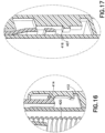
- a button snap 414 of the cartridge button 413 is spaced from a first protrusion 412 of the device housing, as shown in FIGS. 15 and 16 .
- a snap 416 of a cartridge housing 415 is spaced from a second protrusion 407 of the cartridge housing 415, as shown in FIGS. 15 and 17 . Teeth 410 of the cartridge housing 415 engage a compression spring 420 to space the compression spring 420 from a stopper 409 disposed in the cartridge 411.
- FIGS. 21 - 26 show the drug delivery device 401 when the cartridge button 413 is depressed.
- the user pushes the cartridge button 413 downwardly into the device housing 403 to prime and pressurize the cartridge 411.
- the cartridge button 413 is locked into the device housing 403, as shown in FIG. 21 and 22 , when the button snap 414 passes over the first protrusion 412.
- the snaps 416 of the cartridge housing 415 lock the cartridge housing 415 into the device housing 403, as shown in FIGS.
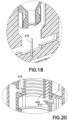
- the septum-piercing needle 418 pierces the septum 408 of the cartridge 411, which is positioned by device housing ribs 404, as shown in FIGS. 18 and 24 .
- the cartridge housing 415 has teeth 410 that are flexed radially outwardly, as shown in FIG. 26 , as the cartridge button 413 engages the cartridge housing 415 and pushes the cartridge housing 415 downwardly, thereby flexing the teeth 410 outwardly.
- the compression spring 420 then passes through the teeth 410 of the cartridge housing 415 and engages the stopper 409 of the cartridge 411.
- FIG. 27 illustrates the two-valve system used in the drug delivery device 401.
- a first valve 431 regulates flow between the first chamber 491 of the cartridge 411 and the second chamber 421. Any suitable valve may be used, such as a disk valve ( FIGS. 28 and 29 ) or a flap valve ( FIGS. 30 - 33 ).
- the first valve 431 allows flow from the first chamber 491 of the cartridge 411 to the second chamber 421 when the second chamber is being filled.
- the first valve 431 blocks flow from the second chamber 421 to the first chamber 491 of the cartridge 411 when injecting a medicament dose.
- a second valve 441 regulates flow from the second chamber 421 to the delivery needle 405. Any suitable valve may be used, such as a relief valve ( FIGS. 34 and 35 ).
- the second valve 441 opens when injecting pressure is applied to the second chamber 421.
- a disk valve 433 is shown in FIGS. 28 and 29 .
- the disk valve 433 When pressure is applied from the first chamber 491 of the cartridge 411, as shown in FIG. 28 , the disk valve 433 is spaced away from the conduit 451 such that medicament may flow into the second chamber 421 from the first chamber 491.
- the disk valve 433 When pressure is applied from the plunger 423, as shown in FIG. 29 , the disk valve 433 is moved to a position abutting the fluid conduit 451 such that medicament is prevented from entering the fluid conduit 451 and flowing back to the first chamber 491 of the cartridge 411.
- the disk valve seats against the surface opposite the higher pressure.
- a flap valve 435 is shown in FIGS. 30 - 33 .
- the flap 436 of the flap valve 435 When pressure is applied from the cartridge 411, as shown in FIG. 30 , the flap 436 of the flap valve 435 is disposed substantially horizontally ( FIG. 33 ) such that medicament may flow into the second chamber 421.
- the flap 436 of the flap valve 435 When pressure is applied from the plunger, as shown in FIG. 31 , the flap 436 of the flap valve 435 is moved downwardly ( FIG. 32 ) such that medicament is prevented from entering the fluid conduit 451 and flowing back to the first chamber 491 of the cartridge 411.
- FIGS. 34 and 35 illustrate operation of a pressure relief valve 443 when used as the second valve.
- the pressure relief valve 443 is in a first position that prevents medicament from exiting the second chamber 421 when the pressure in the second chamber 421 is less than the pre-load pressure of the pressure relief valve (such as a rubber stopper).
- the pressure relief valve moves downwardly to a second and open position to allow medicament to exit the second chamber 421.
- the first valve 431 prevents medicament from entering the fluid conduit 451 and flowing back to the first chamber 491 of the cartridge.
- FIGS. 36 - 39 illustrate filling of the second chamber 421.
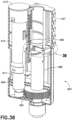
- a ratchet arm 425 holds the plunger 423 in place, as shown in FIGS. 36 and 37 .
- the ratchet arm 425 engages teeth 424 of the plunger 423, as shown in FIG. 37 .
- FIGS. 40 - 44 illustrate setting a dose with the drug delivery device 401.
- a clutch 463 engages a dose setting member or wheel 461 to prevent slippage of the dose setting wheel 461 during an injection.
- the clutch 463 prevents the dose setting wheel 461 from being rotated.
- the clutch 463 disengages the dose setting wheel 461 for dialing a medicament dose by separating the dose setting wheel 461 from the clutch 463, as shown in FIGS. 42 and 44 .
- Rotating the dose wheel 461 rotates the lead screw 465, which in turn moves the dose slider 466 to the desired level. As shown in FIG.
- the dose slider 466 is lifted to a first position with the plunger 423 when the medicament fills the second chamber 421.
- the dose setting wheel 461 is then rotated to move the dose slider to a second position corresponding to the desired medicament dose.
- the dose slider is moved to a position in which the dose slider 466 abuts a lip 467 of the device housing 403.
- a medicament dose less than a full dose results in the dose slider 466 being set at a position between the housing lip 467 and the top of the plunger 423, as shown in FIG. 42 .
- the dose setting wheel 461 is separated from the clutch 463 and the dose slider 466 is moved to the correct dose setting.
- the plunger 423 does not lift when depressing the cartridge button 413 to fill the second chamber 421, thereby indicating the absence of sufficient medicament to deliver a medicament dose.
- FIGS. 45 - 49 illustrate the operation of delivering a dose.
- the plunger 423 is pushed downwardly to deliver the medicament dose.
- the clutch 463 engages the dose setting wheel 461 to prevent movement of the dose setting wheel, thereby preventing the amount of the medicament dose delivered from changing.
- the injection stops when the plunger button 468 abuts the dose slider 466, as shown in FIG. 45 , thereby having delivered the set medicament dose.
- a hook 485 of the dose slider 466 engages the ratchet arm 425 to limit upper movement of the dose slider 466, as shown in FIG. 40 .
- the dose slider 466 has a locking arm 486 that engages teeth 487 that allows for upward movement of the dose slider 466 and prevents downward movement of the dose slider 466.
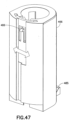
- the dose slider 466 is flexible/collapsible, as shown in FIG. 47 , to disengage the locking arm 486 from the teeth 487 to allow the dose slider 466 to be moved downwardly to set the medicament dose.
- the drug delivery device according to exemplary embodiments of the present invention can be used as a reconstituting drug delivery system.
- the first chamber contains a diluent.
- the second chamber which can be removable/replaceable, contains a solid drug. Accordingly, the drug delivery device enables a reconstitution or resuspension system.
- the first chamber can store sufficient diluent for many injections, and the second chamber can store a solid drug for fewer injections, such as one or two.
- the drug delivery device according to exemplary embodiments of the present invention can be used as a reconstitution system, including as a reconstitution system for high pressure injections.
Landscapes
- Health & Medical Sciences (AREA)
- Vascular Medicine (AREA)
- Engineering & Computer Science (AREA)
- Anesthesiology (AREA)
- Biomedical Technology (AREA)
- Heart & Thoracic Surgery (AREA)
- Hematology (AREA)
- Life Sciences & Earth Sciences (AREA)
- Animal Behavior & Ethology (AREA)
- General Health & Medical Sciences (AREA)
- Public Health (AREA)
- Veterinary Medicine (AREA)
- Infusion, Injection, And Reservoir Apparatuses (AREA)
Description
- This application claims the benefit under 35 U.S.C. § 119(e) of
U.S. Provisional Application Serial No. 61/193,593, filed December 9, 2008 - The present invention relates generally to a drug delivery device that facilitates high pressure medication injections. More particularly, the present invention relates to a drug delivery device that diverts high pressures away from the original drug container to prevent medication leakage and inaccurate doses. Still more particularly, the present invention relates to a drug delivery device having a secondary chamber that amplifies the injection force, thereby facilitating intradermal medication injections.
- Insulin and other injectable medications are commonly given with syringes into the intradermal layer of the skin and other dense tissues. Intradermal medication injections result in faster uptake of the medication, thereby resulting in improved therapy. Such injections require higher injection pressures, upwards of 200 psi, than traditional subcutaneous injections.
- Techniques and devices are known for administering an injection into the intradermal region of the skin. One method, commonly referred to as the Mantoux technique, uses a "standard" needle and syringe, i.e., a syringe typically used to administer intramuscular or subcutaneous injections. The health care provider administering the injection follows a specific procedure that requires a somewhat precise orientation of the syringe with regard to the patient's skin as the injection is administered. The health care provider must also attempt to precisely control the penetration depth of the needle into the patient's skin to ensure that it does not penetrate beyond the intradermal region. Such a technique is complicated, difficult to administer, and often may only be administered by an experienced health care professional.
- A
conventional syringe 101 is shown inFIG. 1 . Theneedle 103 is sufficiently long to deliver the drug to the subcutaneous region of the skin. However, a user would not be able to easily deliver the medicament to the intradermal region of the skin, as discussed above. - Existing drug delivery pens offer several advantages over syringe-based systems for delivering insulin subcutaneously. Reusable drug delivery pens hold 20 or more doses without requiring the drug cartridge to be refilled. Dose setting is achieved simply with the use of a dial. However, those injection systems are designed for low pressure subcutaneous injections. Intradermal injection of insulin and other medications provides faster uptake of the drug, thereby leading to improved therapy. Existing drug delivery pens have several limitations regarding intradermal drug delivery. First, the mechanical advantage provided by the pen is minimal and requires the user to supply upwards of 20 lbs of force to generate sufficient pressure. Second, the pen components can be damaged by this high force, resulting in leaking and inaccuracy at the high pressures.
- Drug delivery pens, such as the exemplary
drug delivery pen 100 shown inFIGS. 2 and3 , are designed for subcutaneous injections and typically comprise a dose knob/button 24, anouter sleeve 13, and acap 21. The dose knob/button 24 allows a user to set the dosage of medication to be injected. Theouter sleeve 13 is gripped by the user when injecting medication. Thecap 21 is used by the user to securely hold thedrug delivery pen 100 in a shirt pocket, purse or other suitable location and provide cover/protection from accidental needle injury. -
FIG. 3 is an exploded view of thedrug delivery pen 100 ofFIG. 2 . The dose knob/button 24 has a dual purpose and is used both to set the dosage of the medication to be injected and to inject the dosed medicament via theleadscrew 7 and stopper 15 through themedicament cartridge 12, which is attached to the drug delivery pen through alower housing 17. In standard drug delivery pens, the dosing and delivery mechanisms are all found within theouter sleeve 13 and are not described in greater detail here as they are understood by those knowledgeable of the prior art. The distal movement of the plunger or stopper 15 within themedicament cartridge 12 causes medication to be forced into theneedle 11 of thehub 20. Themedicament cartridge 12 is sealed byseptum 16, which is punctured by a septum penetratingneedle cannula 18 located within thehub 20. Thehub 20 is preferably screwed onto thelower housing 17, although other attachment means can be used, such as attaching to the cartridge. To protect a user, or anyone who handles thepen injection device 100, anouter cover 69, which attaches to thehub 20, covers the hub. Aninner shield 59 covers thepatient needle 11 within theouter cover 69. Theinner shield 59 can be secured to thehub 20 to cover the patient needle by any suitable means, such as an interference fit or a snap fit. Theouter cover 69 and theinner shield 59 are removed prior to use. Thecap 21 fits snugly againstouter sleeve 13 to allow a user to securely carry thedrug delivery pen 100. - The
medicament cartridge 12 is typically a glass tube sealed at one end with theseptum 16 and sealed at the other end with thestopper 15. Theseptum 16 is pierceable by aseptum penetrating cannula 18 in thehub 20, but does not move with respect to themedicament cartridge 12. Thestopper 15 is axially displaceable within themedicament cartridge 12 while maintaining a fluid tight seal. Further drug delivery devices are known fromUS 2007/060894 ,US 2007/197976 ,US 2006/229562 ,US 2003/050602 andWO 98/11926 - The backpressure in subcutaneous injections is not very large, while the backpressure associated with intradermal injections may be many times greater than that of subcutaneous injections. Existing drug delivery pens require a large force to inject medication into the intradermal layer, thereby making the intradermal medication injection difficult. For example, the backpressure often exceeds 200 psi for an intradermal injection, while the backpressure for a subcutaneous injection is generally in the range of 30 - 50 psi. Thus, a need exists for a drug delivery pen that provides a mechanical advantage to facilitate an injecting a medicament dose intradermally. Furthermore, the drug delivery pen components can be damaged due to the high pressures associated with intradermal injections, thereby resulting in medication leakage and dose inaccuracy.
- In accordance with an aspect of the present invention, a drug delivery device is provided that facilitates injecting insulin or other medicaments at high pressures. The invention is defined in claim 1. Advantageous embodiments are subject of the dependent claims.
- The present invention, a drug delivery device has a second chamber that amplifies the injection force, thereby facilitating intradermal medication injections.
- High pressures associated with intradermal injections are diverted from the original medicament container to substantially prevent medication leakage and inaccurate doses.
- In accordance with another aspect of the present invention, a drug delivery device has a dose limiter that prevents a user from dialing a dose that is greater than the available medicament.
- The drug delivery device operates by transporting a bolus of medication from a primary container (or cartridge) to a secondary chamber using a fluid channel and a compression spring, thereby resulting in a positive pressure differential between the cartridge and the secondary chamber. The secondary chamber employs a smaller cross sectional area than the original medicament container to amplify injection pressure at a given input force on a plunger rod. In the ready state, the secondary chamber contains a full bolus (or maximum dose). The user then dials a desired dose that in turn moves a dose setter relative to the plunger rod to indicate the number of units. After the needle is inserted, the plunger rod is depressed to inject the dialed dose into the patient.
- Objects, advantages, and salient features of the invention will become apparent from the following detailed description, which, taken in conjunction with the annexed drawings, discloses exemplary embodiments of the invention.
- The above benefits and other advantages of the various embodiments of the present invention will be more apparent from the following detailed description of exemplary embodiments of the present invention and from the accompanying drawing figures, in which:
-
FIG. 1 is a front elevational view of a syringe; -
FIG. 2 is a perspective view of a drug delivery pen; -
FIG. 3 is an exploded perspective view of the drug delivery pen ofFIG. 2 ; -
FIG. 4 is a perspective view of a drug delivery device according to a first exemplary embodiment of the present invention; -
FIG. 5 is a partial perspective view in cross section of the drug delivery device ofFIG. 4 ; -
FIG. 6 is a front elevational view of the drug delivery device ofFIG. 4 ; -
FIG. 7 is a side elevational view in cross section of the drug delivery device ofFIG. 4 ; -
FIG. 8 is a front elevational view in cross section of the drug delivery device ofFIG. 4 ; -
FIG. 9 is a partial front elevational view in cross section of the drug delivery device ofFIG. 4 ; -
FIG. 10 is a perspective view of a drug delivery device according to a second exemplary embodiment of the present invention; -
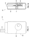
FIG. 11 is a front elevational view of the drug delivery device ofFIG. 10 ; -
FIG. 12 is a side elevational view in cross section of the drug delivery device ofFIG. 10 ; -
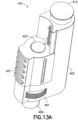
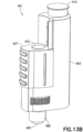
FIGS. 13A ,13B and13C are perspective views of a drug delivery device according to a third exemplary embodiment of the present invention; -
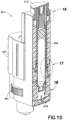
FIGS. 14 - 26 illustrate priming and pressurization of the cartridge of the drug delivery device ofFIG. 13 ; -
FIG. 27 illustrates a two-valve system used in the drug delivery device ofFIG. 13 ; -
FIGS. 28 and 29 illustrate operation of a disk valve as the first valve assembly of the drug delivery device ofFIG. 13 ; -
FIGS. 30 - 33 illustrate operation of a flap valve as the first valve assembly of the drug delivery device ofFIG. 13 ; -
FIGS. 34 and 35 illustrate operation of a pressure relief valve as the second valve assembly of the drug delivery device ofFIG. 13 ; -
FIGS. 36 - 39 illustrate operation of the filling of a second chamber of the drug delivery device ofFIG. 13 ; -
FIGS. 40 - 44 illustrate operation of the dose setting of the drug delivery device ofFIG. 13 ; and -
FIGS. 45 - 49 illustrate delivering the dose with the drug delivery device ofFIG. 13 . - Throughout the drawings, like reference numbers will be understood to refer to like parts, components and structures.
- The drug delivery device according to exemplary embodiments of the present invention allows the user to inject medication at high pressures with lower input forces by decoupling the primary (original) drug container or cartridge and its cross sectional area from the injection mechanics.
- The drug delivery device has advantages in improved dose accuracy and reduced medicament leakage over existing drug delivery pens by diverting high pressures away from the cartridge, particularly the cartridge stopper. At high pressures, the cartridge stopper can deform, which can change the delivery volume and result in dose inaccuracies. Additionally, when the cartridge stopper is allowed to equilibrate and return to its natural volume after the needle is removed from the intradermal space and the back pressure dissipates, unwanted expulsion of the medicament can occur.
- In an exemplary embodiment of the present invention shown in
FIGS. 4 - 9 , adrug delivery device 201 injects insulin or other medicaments at high pressures. Afirst chamber 205 of acartridge 211 and asecond chamber 221 are disposed in adevice housing 202. Aneedle hub 204 is connected to thehousing 202. Aneedle 203 is rigidly fixed in theneedle hub 204 and communicates with thesecond chamber 221. Preferably, theneedle 203 is an intradermal needle. Alternatively, the needle may be a subcutaneous needle. Preferably, the needle is a small gauge needle, such as a 34 gauge needle. The drug delivery device according to exemplary embodiments of the present invention injects insulin, high viscosity medicaments, or other medicaments at high pressures. - A bolus of medication is transported from the
first chamber 205 of the primary container (or cartridge) 211 to thesecond chamber 221 using afluid channel 231 and acompression spring 222, thereby resulting in a positive pressure differential between thecartridge 211 and thesecond chamber 221. Thesecond chamber 221 employs a smaller cross sectional area than thefirst chamber 205 of thecartridge 211 to amplify injection pressure at a given input force on aplunger rod 212. Thecompression spring 222 extends between aspring housing 223 and astopper 215 disposed in thecartridge 211. Thespring housing 223 extends externally of thedevice housing 202 such that thespring housing 223 is accessible by the user. - In the ready state, the
second chamber 221 contains a full bolus (or maximum dose). The user then dials a desired dose on adose wheel 213 that in turn moves a dose setter relative to theplunger rod 212 to indicate the number of units. The size of the dialed dose may be indicated on theplunger rod 212. After theneedle 203 is inserted, theplunger rod 212 is depressed to inject the dialed medicament dose into the patient. Thedrug delivery device 201 diverts the high pressure from thefirst chamber 205 of thecartridge 211 to prevent medication leakage and inaccurate doses. As shown inFIG. 6 , a longitudinal axis through the center of thedose setting wheel 213 is substantially parallel to a direction of travel of theplunger rod 212. - As shown in
FIGS. 4-9 , the injection pressure is decoupled from thecartridge 211 by moving the medicament to asecond chamber 221 via a conduit (fluid channel) 231 using a pressure (created by the user input force that releases the compression spring 222) in thecartridge 211 and a two-valve system for injecting the dialed dose from thesecondary chamber 221 into the patient. Thefirst valve 214 opens to allow thesecond chamber 221 to fill while thesecond valve 216 is closed. During injection, thefirst valve 214 closes and thesecond valve 216 opens to allow the medicament dose to be injected. Thesecond chamber 221 has a smaller cross sectional area than thefirst chamber 205 of thecartridge 211 thus providing higher pressure with the same user input force. Using the relationship of pressure, force and area, P = F/A, asecond chamber 221 with half the cross sectional area of thefirst chamber 205 produces twice the pressure at a given load. - Improved dose accuracy and reduced "drooling" problems related to cartridge stopper effects under high pressure are obtained by decoupling the high injection pressure from the primary drug container (cartridge) 211 and into a less-pressure sensitive (in terms of deformation)
second chamber 221 andstopper 224. - Further, dose accuracy is higher than that of existing drug delivery pens as the travel distance of the
plunger rod stopper 224 to deliver 1 unit of medication out of the smallersecond chamber 221 is approximately 1 mm when compared to the approximately 0.15 mm travel distance of thecartridge stopper 215 to deliver 1 unit out of the largerfirst chamber 205 of thecartridge 211. This improved dose accuracy over existing drug delivery pens is significant, particularly at low dose ranges. - Component deformation due to high pressure (or user force) is also limited as the user force is applied directly to the linearly
moveable plunger rod 212 of the smallersecond chamber 221, thereby eliminating the need for force transfer and amplification mechanisms (from the user input ondose knob 24 to thecartridge stopper 15 ofFIG. 3 ) often used in existing drug delivery pens. In most existing drug delivery pens, the dose delivered is the result of a linear displacement of a drive screw 7 (FIG. 3 ) that translates a given length dependent on the dialed bolus volume. The dialed bolus determines the stroke length of the injection. The user imparts a force on the dose knob 24 (FIG. 3 ) and completes the stroke length of the injection. The force and stroke of the injection motion are translated into a torque. The torque is then used to drive thedrive screw 7 linearly forward. This type of system can produce inaccuracies at the low end of the dosing range due to the complex relationship between the initial stroke and the final drive screw motion. - After the initial priming mechanism of the
cartridge 211 is engaged (a septum-piercing needle piercing a septum of the cartridge 211), thecompression spring 222 is released, pressurizing thecartridge 211. - Medicament is moved from the
first chamber 205 of thecartridge 211 through thefluid conduit 231 into thesecond chamber 221 that is equipped with two one-way valves second chamber 221 is accomplished by exerting a force Fcs on theoriginal container 211 using acompression spring 222 that creates a pressure greater than the opening pressure of the first valve, V1, 214 but less than the opening pressure of the second external valve, V2, 216. During the injection, the user depresses theplunger rod 212 and the pressure inside thesecond chamber 221 rises until the pressure exceeds the cracking pressure of the second valve, V2, 216 (and opens the second valve 216) and backpressure from the intradermal space, at which state the medicament dose is delivered. - The
second chamber 221 has a smaller cross sectional area than thefirst chamber 205 of thecartridge 211, thereby providing higher pressure using the same user input force. Standard 3.0 mL insulin cartridges have a diameter of approximately 9.7 mm, thereby resulting in a cross sectional area of A = πr2 = 4.852 * 3.14159 = 73.9 mm2. In a preferred embodiment of thedrug delivery device 201, thesecond chamber 221 of thedrug delivery device 201 has a diameter of 3.5 mm resulting in a cross sectional area of 1.752 * 3.14159 = 9.62 mm2. For a given pressure, P, a force multiplication is achieved using the following relationships: P = F1/A1, P = F2/A2. Therefore, F1/A1 = F2/A2. The force multiplier Mf, F1/F2, becomes the ratio of the areas, A1/A2, Mf = 73.9/9.62 = 7.7. - Therefore, the
drug delivery device 201 according to an exemplary embodiment of the present invention requires approximately seven (7) times less force to achieve the same injection pressure as a device that applies force directly to the insulin cartridge 12 (FIG. 3 ) without force amplification. - Alternatively, as shown in
FIGS. 10- 12 , the user dials a medicament dose by turning adose setting wheel 303 of adrug delivery device 301 according to a second exemplary embodiment of the present invention. As shown inFIG. 11 , a longitudinal axis through a center of thedose setting wheel 303 is substantially perpendicular to a direction of the travel of aplunger rod 313 driven by thedose setting wheel 303. Otherwise, the functionality and underlying technical principles of thedrug delivery device 301 are substantially similar to those of the first exemplary embodiment shown inFIGS. 4-9 . - As shown in
FIG. 12 , a dosesetting wheel gear 305 is rotatably engaged with a plunger rod gear 311. The dosesetting wheel gear 305 is rotated by thedose setting wheel 303, which rotates the plunger rod gear 311. The plunger rod gear 311 is fixed to thedevice housing 302 and is rotatably disposed on theplunger rod 313. Accordingly, rotation of the plunger rod gear 311 causes theplunger rod 313 to move linearly through the fixed plunger rod gear 311. Rotation of thedose setting wheel 305 when setting a medicament dose results in upward travel of theplunger rod 313, as shown inFIG. 11 . Theplunger rod 313 is then pushed back into thedevice housing 302 to inject a medicament dose from the second chamber and into a patient's skin at an injection site. - Another exemplary embodiment of a
drug delivery device 401 of the present invention is shown inFIGS. 13 - 49 . Thedrug delivery device 401 operates similarly to thedrug delivery device 201 according to the first exemplary embodiment shown inFIGS. 4 - 9 . A medicament dose is set, the second chamber is filled, and the medicament dose is delivered intradermally. Thedrug delivery device 401 allows priming and pressurization of the cartridge, employs valves to activate filling of the second chamber and dose delivery, and allows a medicament dose to be set. -
FIGS. 14 - 26 illustrate the operation of cartridge priming and pressurization.FIGS. 16 - 20 show thedrug delivery device 401 in a shipping state. Thecartridge 411 is pressurized and connected to the injection path upon first use. Prior to the first use, thecartridge 411 is in a first position such that acartridge septum 408 is spaced from a septum-piercingneedle 418, as shown inFIGS. 15 and19 . Abutton snap 414 of thecartridge button 413 is spaced from afirst protrusion 412 of the device housing, as shown inFIGS. 15 and16 . Asnap 416 of acartridge housing 415 is spaced from asecond protrusion 407 of thecartridge housing 415, as shown inFIGS. 15 and17 .Teeth 410 of thecartridge housing 415 engage acompression spring 420 to space thecompression spring 420 from astopper 409 disposed in thecartridge 411. - To prime and pressurize the
cartridge 411, thecartridge 411 is moved from the first position shown inFIGS. 15 - 20 to a second position shown inFIGS. 21-26 in which the septum-piercingneedle 418 pierces thecartridge septum 408.FIGS. 21 - 26 show thedrug delivery device 401 when thecartridge button 413 is depressed. The user pushes thecartridge button 413 downwardly into thedevice housing 403 to prime and pressurize thecartridge 411. Thecartridge button 413 is locked into thedevice housing 403, as shown inFIG. 21 and22 , when thebutton snap 414 passes over thefirst protrusion 412. Thesnaps 416 of thecartridge housing 415 lock thecartridge housing 415 into thedevice housing 403, as shown inFIGS. 21 and23 , by passing over thesecond protrusion 410. The septum-piercingneedle 418 pierces theseptum 408 of thecartridge 411, which is positioned bydevice housing ribs 404, as shown inFIGS. 18 and24 . Thecartridge housing 415 hasteeth 410 that are flexed radially outwardly, as shown inFIG. 26 , as thecartridge button 413 engages thecartridge housing 415 and pushes thecartridge housing 415 downwardly, thereby flexing theteeth 410 outwardly. Thecompression spring 420 then passes through theteeth 410 of thecartridge housing 415 and engages thestopper 409 of thecartridge 411. -
FIG. 27 illustrates the two-valve system used in thedrug delivery device 401. Afirst valve 431 regulates flow between thefirst chamber 491 of thecartridge 411 and thesecond chamber 421. Any suitable valve may be used, such as a disk valve (FIGS. 28 and 29 ) or a flap valve (FIGS. 30 - 33 ). Thefirst valve 431 allows flow from thefirst chamber 491 of thecartridge 411 to thesecond chamber 421 when the second chamber is being filled. Thefirst valve 431 blocks flow from thesecond chamber 421 to thefirst chamber 491 of thecartridge 411 when injecting a medicament dose. Asecond valve 441 regulates flow from thesecond chamber 421 to thedelivery needle 405. Any suitable valve may be used, such as a relief valve (FIGS. 34 and 35 ). Thesecond valve 441 opens when injecting pressure is applied to thesecond chamber 421. - A
disk valve 433 is shown inFIGS. 28 and 29 . When pressure is applied from thefirst chamber 491 of thecartridge 411, as shown inFIG. 28 , thedisk valve 433 is spaced away from theconduit 451 such that medicament may flow into thesecond chamber 421 from thefirst chamber 491. When pressure is applied from theplunger 423, as shown inFIG. 29 , thedisk valve 433 is moved to a position abutting thefluid conduit 451 such that medicament is prevented from entering thefluid conduit 451 and flowing back to thefirst chamber 491 of thecartridge 411. The disk valve seats against the surface opposite the higher pressure. - A
flap valve 435 is shown inFIGS. 30 - 33 . When pressure is applied from thecartridge 411, as shown inFIG. 30 , theflap 436 of theflap valve 435 is disposed substantially horizontally (FIG. 33 ) such that medicament may flow into thesecond chamber 421. When pressure is applied from the plunger, as shown inFIG. 31 , theflap 436 of theflap valve 435 is moved downwardly (FIG. 32 ) such that medicament is prevented from entering thefluid conduit 451 and flowing back to thefirst chamber 491 of thecartridge 411. -
FIGS. 34 and 35 illustrate operation of apressure relief valve 443 when used as the second valve. As shown inFIG. 34 , thepressure relief valve 443 is in a first position that prevents medicament from exiting thesecond chamber 421 when the pressure in thesecond chamber 421 is less than the pre-load pressure of the pressure relief valve (such as a rubber stopper). When the pressure in thesecond chamber 421 exceeds the pre-load pressure of thepressure relief valve 443, as shown inFIG. 35 , the pressure relief valve moves downwardly to a second and open position to allow medicament to exit thesecond chamber 421. Thefirst valve 431 prevents medicament from entering thefluid conduit 451 and flowing back to thefirst chamber 491 of the cartridge. -
FIGS. 36 - 39 illustrate filling of thesecond chamber 421. Aratchet arm 425 holds theplunger 423 in place, as shown inFIGS. 36 and37 . Theratchet arm 425 engages teeth 424 of theplunger 423, as shown inFIG. 37 . Pushing afill button 427 inwardly disengages theratchet arm 425 from the teeth 424 of theplunger 423, as shown inFIG. 39 , thereby allowing thesecond chamber 421 to fill with medicament supplied throughconduit 451 from thefirst chamber 491 of thecartridge 411 and theplunger 423 to move upwardly, as shown inFIG. 38 . -
FIGS. 40 - 44 illustrate setting a dose with thedrug delivery device 401. As shown inFIGS. 40 and41 , a clutch 463 engages a dose setting member orwheel 461 to prevent slippage of thedose setting wheel 461 during an injection. The clutch 463 prevents thedose setting wheel 461 from being rotated. As shown inFIGS. 42 and43 , the clutch 463 disengages thedose setting wheel 461 for dialing a medicament dose by separating thedose setting wheel 461 from the clutch 463, as shown inFIGS. 42 and44 . Rotating thedose wheel 461 rotates thelead screw 465, which in turn moves thedose slider 466 to the desired level. As shown inFIG. 40 , thedose slider 466 is lifted to a first position with theplunger 423 when the medicament fills thesecond chamber 421. Thedose setting wheel 461 is then rotated to move the dose slider to a second position corresponding to the desired medicament dose. To fully inject the full medicament dose in thesecond chamber 421, the dose slider is moved to a position in which thedose slider 466 abuts alip 467 of thedevice housing 403. A medicament dose less than a full dose results in thedose slider 466 being set at a position between thehousing lip 467 and the top of theplunger 423, as shown inFIG. 42 . To correct a set medicament dose, thedose setting wheel 461 is separated from the clutch 463 and thedose slider 466 is moved to the correct dose setting. Furthermore, when no medicament is remaining in thefirst chamber 491 of thecartridge 411, theplunger 423 does not lift when depressing thecartridge button 413 to fill thesecond chamber 421, thereby indicating the absence of sufficient medicament to deliver a medicament dose. -
FIGS. 45 - 49 illustrate the operation of delivering a dose. Theplunger 423 is pushed downwardly to deliver the medicament dose. The clutch 463 engages thedose setting wheel 461 to prevent movement of the dose setting wheel, thereby preventing the amount of the medicament dose delivered from changing. The injection stops when theplunger button 468 abuts thedose slider 466, as shown inFIG. 45 , thereby having delivered the set medicament dose. - A
hook 485 of thedose slider 466 engages theratchet arm 425 to limit upper movement of thedose slider 466, as shown inFIG. 40 . Thedose slider 466 has alocking arm 486 that engagesteeth 487 that allows for upward movement of thedose slider 466 and prevents downward movement of thedose slider 466. Thedose slider 466 is flexible/collapsible, as shown inFIG. 47 , to disengage thelocking arm 486 from theteeth 487 to allow thedose slider 466 to be moved downwardly to set the medicament dose. - Alternatively, the drug delivery device according to exemplary embodiments of the present invention can be used as a reconstituting drug delivery system. The first chamber contains a diluent. The second chamber, which can be removable/replaceable, contains a solid drug. Accordingly, the drug delivery device enables a reconstitution or resuspension system. The first chamber can store sufficient diluent for many injections, and the second chamber can store a solid drug for fewer injections, such as one or two. Accordingly, the drug delivery device according to exemplary embodiments of the present invention can be used as a reconstitution system, including as a reconstitution system for high pressure injections.
- The foregoing embodiments and advantages are merely exemplary and are not to be construed as limiting the scope of the present invention. The description of exemplary embodiments of the present invention is intended to be illustrative, and not to limit the scope of the present invention. Various modifications, alternatives and variations will be apparent to those of ordinary skill in the art, and are intended to fall within the scope of the invention as defined in the appended claims.
Claims (9)
- A dual-chambered drug delivery device, comprising:a first chamber (205) in which a medicament is stored;a dose setting member (213) for setting a medicament dose, said dose setting member being rotatable to set the medicament dose by adjusting a position of a plunger rod (212) connected to a second chamber (221), said dose setting member not being axially moveable, a longitudinal centerline of the dose setting member being parallel to a longitudinal centerline of the second chamber;the second chamber in fluid communication with said first chamber, said second chamber having a smaller cross sectional area than said first chamber, a longitudinal centerline of the first chamber being substantially parallel to and offset from the longitudinal centerline of the second chamber, the medicament dose being transferred to said second chamber from said first chamber by a force from a spring (222) toward a stopper (215) in the first chamber prior to injecting the medicament dose; anda needle (203) communicating with said second chamber for injecting the medicament dose into an injection site when the plunger rod is depressed, whereina first valve (214) is open and a second valve (216) is closed when a pressure inside the first chamber is greater than an opening pressure of the first valve and less than an opening pressure of the second valve to transfer the medicament dose from the first chamber to the second chamber when the second chamber is being filled, and the first valve is closed and the second valve is open when injection pressure is applied to the second chamber such that a pressure inside the second chamber exceeds the opening pressure of the second valve to block the medicament dose flowing from the second chamber to the first chamber when injecting the medicament dose from the second chamber through the needle and into the injection site; andthe pressure in the first chamber is decoupled from a pressure in the second chamber via the first valve and the second valve.
- The dual-chambered drug delivery device according to claim 1, wherein
a first longitudinal axis through said needle is parallel to and spaced from the longitudinal centerline through said first chamber. - The dual-chambered drug delivery device according to claim 1, wherein
the longitudinal centerline through said dose setting member is substantially parallel or substantially perpendicular to a longitudinal axis through said needle. - The dual-chambered drug delivery device according to claim 3, whereina plunger rod gear (311) is disposed on the plunger rod; anda cam wheel gear (305) connected to said dose setting member and rotatably engaged with said plunger rod gear such that rotation of said dose setting member rotates said cam wheel gear and rotation of said cam wheel gear rotates said plunger rod gear, and rotation of said plunger rod gear moves said plunger rod from a first position to a second position.
- The dual-chambered drug delivery device according to claim 1, further comprising:
a cartridge (21) having the first chamber; whereinsaid second chamber having a smaller cross sectional area than said first chamber; andthe medicament dose being equal to or less than the portion of the medicament transferred to said second chamber - The dual-chambered drug delivery device according to claim 5, whereinsaid first valve comprises a flap (435) or disk valve (433); andsaid second valve comprises a pressure relief valve (443).
- The dual-chambered drug delivery device according to claim 5, wherein
the plunger rod is moved when the medicament portion is transferred to said second chamber. - The dual-chambered drug delivery device according to claim 7, whereinrotation of said dose setting member moves a dose slider from a first position flush with a free end of said plunger rod to a second position corresponding to the medicament dose to be delivered; anda clutch (463) engages said dose setting member to prevent rotation of said dose setting member when the medicament dose is not being set.
- The dual-chambered drug delivery device according to claim 5, wherein
a ratchet arm (425) engages said plunger rod to prevent movement of said plunger rod, thereby preventing the medicament portion from being transferred to said second chamber.
Applications Claiming Priority (2)
| Application Number | Priority Date | Filing Date | Title |
|---|---|---|---|
| US19359308P | 2008-12-09 | 2008-12-09 | |
| PCT/US2009/006420 WO2010077278A1 (en) | 2008-12-09 | 2009-12-08 | Dual-chambered drug delivery device for high pressure injections |
Publications (4)
| Publication Number | Publication Date |
|---|---|
| EP2355862A1 EP2355862A1 (en) | 2011-08-17 |
| EP2355862A4 EP2355862A4 (en) | 2015-07-08 |
| EP2355862C0 EP2355862C0 (en) | 2024-08-21 |
| EP2355862B1 true EP2355862B1 (en) | 2024-08-21 |
Family
ID=42310041
Family Applications (1)
| Application Number | Title | Priority Date | Filing Date |
|---|---|---|---|
| EP09836478.9A Active EP2355862B1 (en) | 2008-12-09 | 2009-12-08 | Dual-chambered drug delivery device for high pressure injections |
Country Status (5)
| Country | Link |
|---|---|
| US (1) | US9408980B2 (en) |
| EP (1) | EP2355862B1 (en) |
| JP (3) | JP2012511391A (en) |
| CA (1) | CA2746157C (en) |
| WO (1) | WO2010077278A1 (en) |
Families Citing this family (13)
| Publication number | Priority date | Publication date | Assignee | Title |
|---|---|---|---|---|
| CN102186341B (en) * | 2008-10-20 | 2013-12-25 | 荷兰联合利华有限公司 | Antimicrobial composition |
| AU2010297406B2 (en) | 2009-09-24 | 2013-10-17 | Unilever Plc | Disinfecting agent comprising eugenol, terpineol and thymol |
| WO2011151172A2 (en) | 2010-05-31 | 2011-12-08 | Unilever Nv | Skin treatment composition |
| US20130226080A1 (en) * | 2010-11-03 | 2013-08-29 | Sanofi-Aventis Deutschland Gmbh | Medicated module for a drug delivery device |
| WO2012072554A1 (en) * | 2010-11-29 | 2012-06-07 | Sanofi-Aventis Deutschland Gmbh | Drug delivery device |
| WO2012076310A1 (en) | 2010-12-07 | 2012-06-14 | Unilever Nv | An oral care composition |
| MX2014005405A (en) | 2011-11-03 | 2014-06-23 | Unilever Nv | A personal cleaning composition. |
| GB2510093A (en) * | 2012-10-04 | 2014-07-30 | Owen Mumford Ltd | Pen injector with a mechanism for expelling therapeutic material by negative pressure |
| EP4144390A3 (en) | 2013-06-18 | 2023-07-12 | Enable Injections, Inc. | Vial transfer and injection apparatus and method |
| US20160213863A1 (en) | 2013-08-29 | 2016-07-28 | Carebay Europe Ltd | Droplet Medicament Delivery Device |
| TWI746569B (en) | 2016-06-08 | 2021-11-21 | 瑞士商瑞健醫療股份有限公司 | Dosiergerat, injektionsvorrichtung und verwendung |
| JP7053614B2 (en) | 2016-11-28 | 2022-04-12 | エスエイチエル・メディカル・アーゲー | Device to administer a substance |
| FR3110392A1 (en) * | 2020-05-20 | 2021-11-26 | Eveon | DRUG PREPARATION AND DISTRIBUTION DEVICE |
Family Cites Families (39)
| Publication number | Priority date | Publication date | Assignee | Title |
|---|---|---|---|---|
| DE1992767U (en) * | 1968-03-27 | 1968-08-29 | Peter Dr Pogacar | DEVICE FOR FINE DOSING AND INTRODUCTION OF LIQUIDS FOR ANALYTICAL OR TREATMENT PURPOSES INTO ANOTHER MEDIUM. |
| NL8403937A (en) * | 1984-12-24 | 1986-07-16 | Cornelis Smit | DEVICE FOR DELIVERING A NUMBER OF LIQUID DOSES. |
| US4689042A (en) | 1985-05-20 | 1987-08-25 | Survival Technology, Inc. | Automatic medicament ingredient mixing and injecting apparatus |
| GB9026025D0 (en) | 1990-11-29 | 1991-01-16 | Boehringer Ingelheim Kg | Inhalation device |
| US5298023A (en) | 1991-03-08 | 1994-03-29 | Habley Medical Technology Corporation | Multiple pharmaceutical dispenser with accumulator |
| DE9107574U1 (en) | 1991-06-20 | 1991-08-01 | Heraeus Kulzer GmbH & Co. KG, 63450 Hanau | Syringe-like device for dosing liquids or pastes |
| US5279585A (en) | 1992-02-04 | 1994-01-18 | Becton, Dickinson And Company | Medication delivery pen having improved dose delivery features |
| ZA941881B (en) * | 1993-04-02 | 1995-09-18 | Lilly Co Eli | Manifold medication injection apparatus and method |
| US5549575A (en) | 1994-09-13 | 1996-08-27 | Becton Dickinson And Company | Cartridge retainer assembly for medication delivery pen |
| US5582598A (en) | 1994-09-19 | 1996-12-10 | Becton Dickinson And Company | Medication delivery pen with variable increment dose scale |
| US5569214A (en) | 1994-09-20 | 1996-10-29 | Becton Dickinson And Company | Dose setting knob adapter for medication delivery pen |
| US5674204A (en) | 1995-09-19 | 1997-10-07 | Becton Dickinson And Company | Medication delivery pen cap actuated dose delivery clutch |
| DE19604838A1 (en) | 1996-02-12 | 1997-08-14 | Alfred Von Schuckmann | Device for dispensing liquid in divided quantities |
| ATE209935T1 (en) | 1996-09-20 | 2001-12-15 | Novo Nordisk As | WORKING CYLINDER |
| US5843042A (en) * | 1996-11-06 | 1998-12-01 | Ren; Liang Chen | Oral medicine dispensing device having a metered syringe component and reservoir |
| US6074372A (en) | 1997-06-09 | 2000-06-13 | Novo Nordisk A/S | Dose setting mechanism and an injection syringe having such a dose setting mechanism |
| US5921966A (en) | 1997-08-11 | 1999-07-13 | Becton Dickinson And Company | Medication delivery pen having an improved clutch assembly |
| US5944700A (en) | 1997-09-26 | 1999-08-31 | Becton, Dickinson And Company | Adjustable injection length pen needle |
| US6096010A (en) | 1998-02-20 | 2000-08-01 | Becton, Dickinson And Company | Repeat-dose medication delivery pen |
| US6221053B1 (en) | 1998-02-20 | 2001-04-24 | Becton, Dickinson And Company | Multi-featured medication delivery pen |
| US6248095B1 (en) | 1998-02-23 | 2001-06-19 | Becton, Dickinson And Company | Low-cost medication delivery pen |
| ES2258469T3 (en) | 1999-08-05 | 2006-09-01 | Becton Dickinson And Company | MEDICATION ADMINISTRATION PENCIL. |
| US6277099B1 (en) | 1999-08-06 | 2001-08-21 | Becton, Dickinson And Company | Medication delivery pen |
| US6607508B2 (en) * | 2000-04-27 | 2003-08-19 | Invivotech, Inc. | Vial injector device |
| US6689101B2 (en) * | 2000-05-22 | 2004-02-10 | Pharmacia Ab | Medical arrangement |
| SE0001893D0 (en) * | 2000-05-22 | 2000-05-22 | Pharmacia & Upjohn Ab | Medical arrangement |
| US6537242B1 (en) | 2000-06-06 | 2003-03-25 | Becton, Dickinson And Company | Method and apparatus for enhancing penetration of a member for the intradermal sampling or administration of a substance |
| US6652483B2 (en) | 2000-11-07 | 2003-11-25 | Avant Drug Delivery Systems, Inc. | Needleless jet injector system with separate drug reservoir |
| US20020107501A1 (en) * | 2001-02-02 | 2002-08-08 | Smith James E. | Weight dependent, automatic filling dosage system and method of using same |
| DE10129585A1 (en) | 2001-06-20 | 2003-01-09 | Disetronic Licensing Ag | Device for the dosed administration of an injectable product |
| US7217253B2 (en) | 2001-06-26 | 2007-05-15 | Avant Medical Corp. | Sequential impulse/delivery fluid medicament injector |
| WO2003022330A2 (en) | 2001-09-12 | 2003-03-20 | Becton, Dickinson And Company | Microneedle-based pen device for drug delivery and method for using same |
| AU2003239785A1 (en) * | 2002-07-10 | 2004-02-02 | Novo Nordisk A/S | An injection device with a dose setting limiter |
| DE60308042T2 (en) | 2002-10-01 | 2007-04-12 | Becton Dickinson And Co. | PEN DRY MEDICATION SYRINGE |
| US6932794B2 (en) | 2003-04-03 | 2005-08-23 | Becton, Dickinson And Company | Medication delivery pen |
| EP1633417B1 (en) | 2003-05-30 | 2007-01-31 | Eli Lilly And Company | Multiple chamber medication dispensing apparatus |
| SE526878C2 (en) * | 2003-06-18 | 2005-11-15 | Q Med Ab | Medical pump |
| AU2005231731B2 (en) * | 2004-03-30 | 2010-12-23 | Eli Lilly And Company | Medication dispensing apparatus with spring-driven locking feature enabled by administration of final dose |
| US7645264B2 (en) * | 2005-04-11 | 2010-01-12 | Becton, Dickinson And Company | Injection device with secondary reservoir |
-
2009
- 2009-12-08 EP EP09836478.9A patent/EP2355862B1/en active Active
- 2009-12-08 US US12/998,853 patent/US9408980B2/en active Active
- 2009-12-08 JP JP2011540687A patent/JP2012511391A/en active Pending
- 2009-12-08 CA CA2746157A patent/CA2746157C/en active Active
- 2009-12-08 WO PCT/US2009/006420 patent/WO2010077278A1/en not_active Ceased
-
2014
- 2014-12-05 JP JP2014247466A patent/JP6181634B2/en active Active
- 2014-12-05 JP JP2014247467A patent/JP6002740B2/en active Active
Also Published As
| Publication number | Publication date |
|---|---|
| EP2355862C0 (en) | 2024-08-21 |
| CA2746157A1 (en) | 2010-07-08 |
| JP6002740B2 (en) | 2016-10-05 |
| CA2746157C (en) | 2018-10-30 |
| WO2010077278A1 (en) | 2010-07-08 |
| JP6181634B2 (en) | 2017-08-16 |
| JP2012511391A (en) | 2012-05-24 |
| US9408980B2 (en) | 2016-08-09 |
| US20120004641A1 (en) | 2012-01-05 |
| JP2015042378A (en) | 2015-03-05 |
| EP2355862A1 (en) | 2011-08-17 |
| JP2015042377A (en) | 2015-03-05 |
| EP2355862A4 (en) | 2015-07-08 |
Similar Documents
| Publication | Publication Date | Title |
|---|---|---|
| EP2355862B1 (en) | Dual-chambered drug delivery device for high pressure injections | |
| EP2355869B1 (en) | Multi-stroke delivery pumping mechanism for a drug delivery device for high pressure injections | |
| EP2370135B1 (en) | Lever and gear force multiplier medication delivery system for high pressure injection system | |
| EP2303362B1 (en) | Dual chamber and gear pump assembly for a high pressure delivery system | |
| EP2364372B1 (en) | Open and closed valve medication delivery system for high pressure injections |
Legal Events
| Date | Code | Title | Description |
|---|---|---|---|
| PUAI | Public reference made under article 153(3) epc to a published international application that has entered the european phase |
Free format text: ORIGINAL CODE: 0009012 |
|
| 17P | Request for examination filed |
Effective date: 20110606 |
|
| AK | Designated contracting states |
Kind code of ref document: A1 Designated state(s): AT BE BG CH CY CZ DE DK EE ES FI FR GB GR HR HU IE IS IT LI LT LU LV MC MK MT NL NO PL PT RO SE SI SK SM TR |
|
| RIN1 | Information on inventor provided before grant (corrected) |
Inventor name: SPOOL, IRA Inventor name: ROSEN, MELISSA Inventor name: SCHOONMAKER, RYAN Inventor name: BRUEHWILER, MICHEL |
|
| DAX | Request for extension of the european patent (deleted) | ||
| RIN1 | Information on inventor provided before grant (corrected) |
Inventor name: ROSEN, MELISSA Inventor name: SCHOONMAKER, RYAN Inventor name: BRUEHWILER, MICHEL Inventor name: SPOOL, IRA |
|
| RA4 | Supplementary search report drawn up and despatched (corrected) |
Effective date: 20150610 |
|
| RIC1 | Information provided on ipc code assigned before grant |
Ipc: A61M 5/20 20060101ALI20150603BHEP Ipc: A61M 5/19 20060101ALI20150603BHEP Ipc: A61M 5/48 20060101ALI20150603BHEP Ipc: A61M 5/315 20060101ALI20150603BHEP Ipc: A61M 5/00 20060101AFI20150603BHEP Ipc: A61M 5/31 20060101ALI20150603BHEP |
|
| RAP1 | Party data changed (applicant data changed or rights of an application transferred) |
Owner name: BECTON, DICKINSON AND COMPANY |
|
| STAA | Information on the status of an ep patent application or granted ep patent |
Free format text: STATUS: EXAMINATION IS IN PROGRESS |
|
| 17Q | First examination report despatched |
Effective date: 20180926 |
|
| GRAP | Despatch of communication of intention to grant a patent |
Free format text: ORIGINAL CODE: EPIDOSNIGR1 |
|
| STAA | Information on the status of an ep patent application or granted ep patent |
Free format text: STATUS: GRANT OF PATENT IS INTENDED |
|
| INTG | Intention to grant announced |
Effective date: 20240405 |
|
| GRAS | Grant fee paid |
Free format text: ORIGINAL CODE: EPIDOSNIGR3 |
|
| GRAA | (expected) grant |
Free format text: ORIGINAL CODE: 0009210 |
|
| STAA | Information on the status of an ep patent application or granted ep patent |
Free format text: STATUS: THE PATENT HAS BEEN GRANTED |
|
| AK | Designated contracting states |
Kind code of ref document: B1 Designated state(s): AT BE BG CH CY CZ DE DK EE ES FI FR GB GR HR HU IE IS IT LI LT LU LV MC MK MT NL NO PL PT RO SE SI SK SM TR |
|
| REG | Reference to a national code |
Ref country code: GB Ref legal event code: FG4D |
|
| REG | Reference to a national code |
Ref country code: CH Ref legal event code: EP |
|
| REG | Reference to a national code |
Ref country code: IE Ref legal event code: FG4D |
|
| REG | Reference to a national code |
Ref country code: DE Ref legal event code: R096 Ref document number: 602009065342 Country of ref document: DE |
|
| U01 | Request for unitary effect filed |
Effective date: 20240919 |
|
| U07 | Unitary effect registered |
Designated state(s): AT BE BG DE DK EE FI FR IT LT LU LV MT NL PT RO SE SI Effective date: 20241010 |
|
| U20 | Renewal fee for the european patent with unitary effect paid |
Year of fee payment: 16 Effective date: 20241121 |
|
| PG25 | Lapsed in a contracting state [announced via postgrant information from national office to epo] |
Ref country code: NO Free format text: LAPSE BECAUSE OF FAILURE TO SUBMIT A TRANSLATION OF THE DESCRIPTION OR TO PAY THE FEE WITHIN THE PRESCRIBED TIME-LIMIT Effective date: 20241121 |
|
| PG25 | Lapsed in a contracting state [announced via postgrant information from national office to epo] |
Ref country code: PL Free format text: LAPSE BECAUSE OF FAILURE TO SUBMIT A TRANSLATION OF THE DESCRIPTION OR TO PAY THE FEE WITHIN THE PRESCRIBED TIME-LIMIT Effective date: 20240821 Ref country code: GR Free format text: LAPSE BECAUSE OF FAILURE TO SUBMIT A TRANSLATION OF THE DESCRIPTION OR TO PAY THE FEE WITHIN THE PRESCRIBED TIME-LIMIT Effective date: 20241122 |
|
| PG25 | Lapsed in a contracting state [announced via postgrant information from national office to epo] |
Ref country code: IS Free format text: LAPSE BECAUSE OF FAILURE TO SUBMIT A TRANSLATION OF THE DESCRIPTION OR TO PAY THE FEE WITHIN THE PRESCRIBED TIME-LIMIT Effective date: 20241221 |
|
| PG25 | Lapsed in a contracting state [announced via postgrant information from national office to epo] |
Ref country code: HR Free format text: LAPSE BECAUSE OF FAILURE TO SUBMIT A TRANSLATION OF THE DESCRIPTION OR TO PAY THE FEE WITHIN THE PRESCRIBED TIME-LIMIT Effective date: 20240821 |
|
| PG25 | Lapsed in a contracting state [announced via postgrant information from national office to epo] |
Ref country code: ES Free format text: LAPSE BECAUSE OF FAILURE TO SUBMIT A TRANSLATION OF THE DESCRIPTION OR TO PAY THE FEE WITHIN THE PRESCRIBED TIME-LIMIT Effective date: 20240821 |
|
| PG25 | Lapsed in a contracting state [announced via postgrant information from national office to epo] |
Ref country code: PL Free format text: LAPSE BECAUSE OF FAILURE TO SUBMIT A TRANSLATION OF THE DESCRIPTION OR TO PAY THE FEE WITHIN THE PRESCRIBED TIME-LIMIT Effective date: 20240821 Ref country code: NO Free format text: LAPSE BECAUSE OF FAILURE TO SUBMIT A TRANSLATION OF THE DESCRIPTION OR TO PAY THE FEE WITHIN THE PRESCRIBED TIME-LIMIT Effective date: 20241121 Ref country code: IS Free format text: LAPSE BECAUSE OF FAILURE TO SUBMIT A TRANSLATION OF THE DESCRIPTION OR TO PAY THE FEE WITHIN THE PRESCRIBED TIME-LIMIT Effective date: 20241221 Ref country code: HR Free format text: LAPSE BECAUSE OF FAILURE TO SUBMIT A TRANSLATION OF THE DESCRIPTION OR TO PAY THE FEE WITHIN THE PRESCRIBED TIME-LIMIT Effective date: 20240821 Ref country code: GR Free format text: LAPSE BECAUSE OF FAILURE TO SUBMIT A TRANSLATION OF THE DESCRIPTION OR TO PAY THE FEE WITHIN THE PRESCRIBED TIME-LIMIT Effective date: 20241122 Ref country code: ES Free format text: LAPSE BECAUSE OF FAILURE TO SUBMIT A TRANSLATION OF THE DESCRIPTION OR TO PAY THE FEE WITHIN THE PRESCRIBED TIME-LIMIT Effective date: 20240821 |
|
| PG25 | Lapsed in a contracting state [announced via postgrant information from national office to epo] |
Ref country code: SM Free format text: LAPSE BECAUSE OF FAILURE TO SUBMIT A TRANSLATION OF THE DESCRIPTION OR TO PAY THE FEE WITHIN THE PRESCRIBED TIME-LIMIT Effective date: 20240821 |
|
| PG25 | Lapsed in a contracting state [announced via postgrant information from national office to epo] |
Ref country code: CZ Free format text: LAPSE BECAUSE OF FAILURE TO SUBMIT A TRANSLATION OF THE DESCRIPTION OR TO PAY THE FEE WITHIN THE PRESCRIBED TIME-LIMIT Effective date: 20240821 |
|
| PG25 | Lapsed in a contracting state [announced via postgrant information from national office to epo] |
Ref country code: SK Free format text: LAPSE BECAUSE OF FAILURE TO SUBMIT A TRANSLATION OF THE DESCRIPTION OR TO PAY THE FEE WITHIN THE PRESCRIBED TIME-LIMIT Effective date: 20240821 |
|
| PLBE | No opposition filed within time limit |
Free format text: ORIGINAL CODE: 0009261 |
|
| STAA | Information on the status of an ep patent application or granted ep patent |
Free format text: STATUS: NO OPPOSITION FILED WITHIN TIME LIMIT |
|
| PG25 | Lapsed in a contracting state [announced via postgrant information from national office to epo] |
Ref country code: MC Free format text: LAPSE BECAUSE OF FAILURE TO SUBMIT A TRANSLATION OF THE DESCRIPTION OR TO PAY THE FEE WITHIN THE PRESCRIBED TIME-LIMIT Effective date: 20240821 |
|
| 26N | No opposition filed |
Effective date: 20250522 |
|
| REG | Reference to a national code |
Ref country code: CH Ref legal event code: PL |
|
| PG25 | Lapsed in a contracting state [announced via postgrant information from national office to epo] |
Ref country code: CH Free format text: LAPSE BECAUSE OF NON-PAYMENT OF DUE FEES Effective date: 20241231 |
|
| PG25 | Lapsed in a contracting state [announced via postgrant information from national office to epo] |
Ref country code: IE Free format text: LAPSE BECAUSE OF NON-PAYMENT OF DUE FEES Effective date: 20241208 |
|
| U20 | Renewal fee for the european patent with unitary effect paid |
Year of fee payment: 17 Effective date: 20251119 |
|
| PGFP | Annual fee paid to national office [announced via postgrant information from national office to epo] |
Ref country code: GB Payment date: 20251119 Year of fee payment: 17 |