EP2355075B1 - System for removing a display unit from a multi panel display - Google Patents
System for removing a display unit from a multi panel display Download PDFInfo
- Publication number
- EP2355075B1 EP2355075B1 EP11152749.5A EP11152749A EP2355075B1 EP 2355075 B1 EP2355075 B1 EP 2355075B1 EP 11152749 A EP11152749 A EP 11152749A EP 2355075 B1 EP2355075 B1 EP 2355075B1
- Authority
- EP
- European Patent Office
- Prior art keywords
- display
- display unit
- lift
- lifting
- display units
- Prior art date
- Legal status (The legal status is an assumption and is not a legal conclusion. Google has not performed a legal analysis and makes no representation as to the accuracy of the status listed.)
- Not-in-force
Links
Images


Classifications
-
- G—PHYSICS
- G09—EDUCATION; CRYPTOGRAPHY; DISPLAY; ADVERTISING; SEALS
- G09F—DISPLAYING; ADVERTISING; SIGNS; LABELS OR NAME-PLATES; SEALS
- G09F9/00—Indicating arrangements for variable information in which the information is built-up on a support by selection or combination of individual elements
- G09F9/30—Indicating arrangements for variable information in which the information is built-up on a support by selection or combination of individual elements in which the desired character or characters are formed by combining individual elements
- G09F9/302—Indicating arrangements for variable information in which the information is built-up on a support by selection or combination of individual elements in which the desired character or characters are formed by combining individual elements characterised by the form or geometrical disposition of the individual elements
- G09F9/3026—Video wall, i.e. stackable semiconductor matrix display modules
-
- B—PERFORMING OPERATIONS; TRANSPORTING
- B65—CONVEYING; PACKING; STORING; HANDLING THIN OR FILAMENTARY MATERIAL
- B65G—TRANSPORT OR STORAGE DEVICES, e.g. CONVEYORS FOR LOADING OR TIPPING, SHOP CONVEYOR SYSTEMS OR PNEUMATIC TUBE CONVEYORS
- B65G57/00—Stacking of articles
- B65G57/30—Stacking of articles by adding to the bottom of the stack
- B65G57/301—Stacking of articles by adding to the bottom of the stack by means of reciprocatory or oscillatory lifting and holding or gripping devices
- B65G57/302—Stacking of articles by adding to the bottom of the stack by means of reciprocatory or oscillatory lifting and holding or gripping devices added articles being lifted to substantially stationary grippers or holders
-
- G—PHYSICS
- G09—EDUCATION; CRYPTOGRAPHY; DISPLAY; ADVERTISING; SEALS
- G09F—DISPLAYING; ADVERTISING; SIGNS; LABELS OR NAME-PLATES; SEALS
- G09F9/00—Indicating arrangements for variable information in which the information is built-up on a support by selection or combination of individual elements
- G09F9/30—Indicating arrangements for variable information in which the information is built-up on a support by selection or combination of individual elements in which the desired character or characters are formed by combining individual elements
- G09F9/33—Indicating arrangements for variable information in which the information is built-up on a support by selection or combination of individual elements in which the desired character or characters are formed by combining individual elements being semiconductor devices, e.g. diodes
-
- G—PHYSICS
- G09—EDUCATION; CRYPTOGRAPHY; DISPLAY; ADVERTISING; SEALS
- G09G—ARRANGEMENTS OR CIRCUITS FOR CONTROL OF INDICATING DEVICES USING STATIC MEANS TO PRESENT VARIABLE INFORMATION
- G09G2300/00—Aspects of the constitution of display devices
- G09G2300/02—Composition of display devices
- G09G2300/026—Video wall, i.e. juxtaposition of a plurality of screens to create a display screen of bigger dimensions
Definitions
- Embodiments of the present invention relate generally to multi-panel display systems and, more specifically, to apparatus for removing a display unit from a such systems.
- Electronic display systems are commonly used to display information from computers and other sources. Typical display systems range in size from small displays used in mobile devices to very large displays that are used to display images to thousands of viewers at one time.
- Tiled display walls provide a large-format environment for presenting large high-resolution images by synchronizing and coupling the output from multiple distinct imaging systems. Such large displays may be created by tiling a plurality of smaller display units together. For example, video walls frequently seen in the electronic media typically use multiple display units, such as flat-panel displays, which are tiled to create such large displays.
- An issue with tiled displays is that the gap present between the constituent display units can produce a grid pattern visible to the viewer.
- Figure 1A is a schematic perspective view of a typical tiled display device 100 having an array of display units 102 that are each used to display portions of an image to a viewer 108.
- the array of display units 102 forms a grid pattern 101 found within a displayed image 107, which is shown in Figure 1B .
- Grid pattern 101 may be formed by a frame, bezel, or unilluminated peripheral region circumscribing each of the display units 102, and/or by the gap 103 present between adjacent display units 102.
- Figure 1B is a schematic view of tiled display device 100 in Figure 1 from the perspective of viewer 108 that further illustrates the grid pattern 101 that may be visible to the viewer within displayed image 107.
- gap 103 may be on the order of 1 mm or less.
- Display units 102 for a typical tiled display can be relatively bulky, heavy, and include delicate external components, such as the precisely shaped glass panels often used as an image forming surface. As noted above, in a tiled display device the edges of these glass panels may be placed less than a millimeter apart to avoid producing grid pattern 101. Consequently, removal and replacement of a display unit 102 that is damaged or needs service is problematic due to the risk of damaging additional display units 102 while removing the damaged unit.
- US Pat. 6 704 989 B1 discloses a transportable electronic sign display system and process where electronic display modules are encased in castered protective cases which are broken down on site and assembled in rows of desired length and stackably elevated and maneuvered by a lifting truss. Electronic display modules are lifted from protective case bases with minimal effort or labor.
- One embodiment of the present invention sets forth a system for removing a display unit or components thereof from a tiled display wall in a way that minimizes the risk of damaging the removed display unit and other display units in the tiled display wall.
- a lifting structure is configured to selectively engage and lift one or more display units away from the desired display unit when the lifting structure is raised by a vertical motion actuator.
- the lifting structure is further configured to be free to rotate slightly about a vertical axis when lifting the one or more display units, so that the lifted display units are not constrained to purely vertical translation when lifted away from the desired display unit. Instead, the lifted display units are each free to move slightly to either side so that small conflicts or mismatches with adjacent display units do not interfere with the vertical movement of the lifted display units, thereby avoiding damage during the lifting process.
- Figure 1A is a schematic perspective view of a typical tiled display device having an array of display units that are each used to display portions of an image to a viewer;
- Figure 1B is a schematic view of the tiled display device in Figure 1A from the perspective of a viewer that further illustrates the grid pattern that may be visible to the viewer within a displayed image;
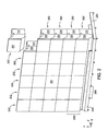
- Figure 2 illustrates a multi-panel display 200 according to various embodiments of the invention
- Figure 3 illustrates a lift system for accessing a display unit in a multi-panel display and a plurality of display units that form a column of the multi-panel display in Figure 2 , according to one embodiment of the invention
- Figure 4 illustrates a perspective view of a lift structure and a support column, according to an embodiment of the invention
- Figure 5 illustrates a plan view of the lift structure of Figure 4 with lifting elements arranged in four lifting positions, according to one embodiment of the invention
- Figure 6 illustrates a perspective view of the lifting structure of Figure 3 engaged with and lifting a display unit, according to one embodiment of the invention
- Figure 7 illustrates a partial perspective view of the column of display units and the lift system in Figure 3 as a display unit is lifted to allow access to a lower display unit, according to one embodiment of the invention
- Figure 8 illustrates a partial perspective view of the column of display units and the lift system in Figure 3 as multiple display units are lifted to allow access to a lower display unit, according to one embodiment of the invention
- Figure 9 illustrates a partial perspective view of the column of display units and the lift system in Figure 3 after the installation of a removable lifting mechanism 900, according to a different embodiment of the invention
- Figure 10 illustrates a partial perspective view of the column of display units and the lift system in Figure 3 after a projection assembly of a display unit has been lifted up and extended out by a removable lifting mechanism, according to the different embodiment of the invention.
- Figure 11 illustrates a perspective view of the column of display units and the lift system in Figure 3 after a projection assembly of a display unit has been lifted up and extended out by a removable lifting mechanism, according to the different embodiment of the invention.
- Multi-panel display 200 includes a plurality of display units 202 assembled to form a display surface 203.
- display surface 203 is a planar viewing surface, while in other embodiments, display surface 203 may be curved.
- display units 202 in Figure 2 are shown positioned above multi-panel display 200 prior to installation.
- Multi-panel display 200 is depicted as a six-tile by five-tile array, i.e., six columns of five display units, but any multi-tile display falls within the scope of the invention.
- multi-panel display 200 includes a base structure 205 configured to provide stability against tipping and a means for seismic restraint.
- base structure 205 is precisely leveled and a first row 206 of display units 202 are mechanically coupled thereto base structure 205 so that first row 206 forms a level datum for the remaining display units 202 of multi-panel display 200.
- Each display unit 202 is a light-based electronic display device, such as a laser-phosphor display (LPD), a light-emitting diode (LED) digital light processing (DLP), or an LED-liquid crystal display (LCD) device, and is configured to operate in conjunction with the other display units 202 to produce a single coherent image for a viewer.
- Each display unit 202 includes a precision frame 210, a projection assembly 220, and a display panel 230.
- Projection assembly 220 is mounted on a precision frame 210
- display panel 230 is mounted on projection assembly 220.
- Precision frame 210 is a structural assembly configured to be mechanically coupled to precision frames 210 of adjacent precision display units 202 to form a rigid structural truss for multi-panel display 200, according to embodiments of the invention.
- a precision frame as defined herein, is a structure having precisely located datum surfaces, projections, and/or other features configured to define the position of the structure when mechanically coupled to another such structure.
- each precision frame 210 includes two precision pins located on a top surface and mating sockets on a bottom surface to accurately set the vertical pitch between each display unit 202 and to laterally and rotationally constrain each display unit when positioned on top of another display unit to prevent tilting (rotation about the z-axis), rocking (rotation about the x-axis), and rotation about the y-axis. Examples of such precision pins are described below in conjunction with Figure 7 .
- each precision frame 210 further includes datum surfaces on each side to further define the lateral position of each display unit 202, i.e., horizontal pitch.
- horizontal latching devices may be employed to further stiffen the structural truss of multi-panel display 200 formed by precision frames 210. Suitable horizontal latching devices that may be used are described in co-pending U.S. patent application SN 13/013,759 , "Latch System for Coupling Precision Frames," filed January 25, 2011.
- precision frame 210 In addition to precision frames 210, no other structure is needed for positioning the plurality of display panels 230 to produce planar display surface 203 of multi-panel display 200. This lack of additional support structure is evident in Figure 2 , where one display unit 202 is shown positioned above multi-panel display 200 prior to installation. It is further noted that while precision frame 210 is described herein as a separate component of each display unit 202, in some embodiments of the invention, precision frame 210 may be integral to each display unit 202.
- Projection assembly 220 includes light sources, optics, and control systems for forming a desired portion of an image on display panel 230, and display panel 230 is the image-forming surface seen by a viewer.
- display unit 202 is a laser-phosphor display (LPD)
- projection assembly 220 includes multiple lasers and associated optics to "paint" different regions of phosphor-containing strips disposed on display panel 230 to produce an image for a viewer, where the optical output energy of each laser paints a different phosphor-containing region of the display.
- adjacent tiles are positioned as close as practicable to each other. Consequently, display panel 230 is a fragile and precisely shaped glass sheet that will be positioned as closely as practicable to and aligned with adjacent display panels to minimize a grid pattern on planar display surface 203 visible to a viewer.
- FIG 3 illustrates a lift system 300 for accessing a display unit in multi-panel display 200 and a plurality of display units 351-355 that form a column 350 of multi-panel display 200 in Figure 2 , according to one embodiment of the invention.
- Lift system 300 includes a lift structure 301, a support column 302 disposed inside lift structure 301, a lift system support frame 310, and a vertical motion actuator 500 (shown in Figure 5 ).
- support column 302 may be a rail situated adjacent to lift structure 301.
- Column 350 can be any column of display units 202 contained in multi-panel display 200 and includes display units 351-355. Structural details and alignment features of display units 351-355 are described below in conjunction with Figure 7 .
- Lift system support frame 310 includes support columns 303 and a top piece 304.
- Lift system support frame 310 serves as an independent structural support system for lift system 300 and is coupled to support column 302 via top piece 304.
- support frame 303 and/or structures mounted thereon can be configured as a vertical rail system that keeps display units 202 aligned as desired during the lifting process. Because lift system support frame 310 is structurally independent from column 350, lift system 300 can be repositioned adjacent to any column 350 in multi-panel display 200 that has a display unit 202 in need of removal or service. Alternatively, one lift system 300 may be installed behind each column 350 making up multi-panel display 200.
- Lift structure 301 is used to lift one or more of the display units of column 350 and thereby facilitate access to one of display units 351-355 for removal or repair.
- Lift structure 301 is a lifting mechanism configured to selectively engage and lift one or more of display units 351-354 when the lifting structure is raised by vertical motion actuator 500.
- Lift structure 301 is further configured to be free to rotate slightly about a vertical axis when lifting the one or more display units so that the lifted display units are not constrained to purely vertical translation when being lifted. For example, lifted display units may be free to rotate approximately ⁇ 10 degrees about a vertical axis during the lifting process before being constrained rotationally by support frame 303 and/or structures mounted thereon.
- lift structure 301 rotates about support column 302, which may be disposed coaxially inside lift structure 301.
- display units 351-354 are each engaged and lifted by a single lifting member and therefore are relatively unconstrained, i.e., are not rigidly held, while translating vertically.
- display units 351-355 that are being lifted by lift structure 301 can move slightly to either side so that small conflicts or mismatches with adjacent tiles do not interfere with the upward or downward movement of the lifted display units, thereby avoiding damage to display panels 230 of display units 202 during the lifting process.
- FIG. 4 illustrates a perspective view of lift structure 301 and support column 302, according to an embodiment of the invention.
- lift structure 301 includes a plurality of lifting members 305 arranged in multiple lift position groups 1-4, where each of these lift position groups: 1) corresponds to a particular lift position of lift structured 301; 2) is made up of vertically aligned lifting members 305; and 3) is radially offset on lifting structure 301 from the other lift positions.
- each of lift position groups 1-4 includes a unique combination of lifting members 305 configured to engage and lift a unique combination of display units 202.
- lift position group 1 is positioned to engage and lift display unit 351 with a single lifting member 305 when lift structure 301 is raised by vertical motion actuator 500.
- lift position group 2 is positioned to engage and lift display units 351 and 352;
- lift position group 3 is positioned to engage and lift display units 351-353; and
- lift position group 4 is positioned to engage and lift display units 351-354 .
- the relative radial positions of lift positions 1-4 are illustrated more clearly in Figure 5 .
- FIG. 5 illustrates a plan view of lift structure 301 with lifting elements 305 arranged in four lifting positions, according to one embodiment of the invention.
- lifting positions groups 1-4 are each positioned at a different radial location on lifting structure 301.
- Support column 302 is disposed in lift structure 301 to serve as a support structure for lift structure 301 and to provide a vertical track along which lift structure 301 translates when lifted and lowered by vertical motion actuator 500.
- Vertical motion actuator 500 raises and lowers lift structure 301 and may be any linear actuator known in the art, such as a pneumatic actuator or a lead-screw-based actuator.
- vertical motion actuator 500 is depicted inside support column 302. In other embodiments, vertical motion actuator 500 may be located adjacent to lift structure 301 and outside support column 302. When selecting a particular lift position, lift structure 301 may be rotated manually or by means of a motorized or otherwise powered actuator.
- lift structure 301 When installed in multi-panel display 200, display panels 230 of display units 202 are closely positioned, i.e., they have a separation on the order of about 1 mm or less. Because lift structure 301 is configured to allow slight movement of display units 351-355 such a small gap is likely to result in damage to display panels 230 during the lifting process. In some embodiments, lifting elements 305 of lift structure 301 are configured to minimize contact between vertically adjacent display units 351-355 during the lifting and lowering process to prevent such damage.
- lifting elements 305 in one lift position group are configured to sequentially engage and lift the desired display units in column 350 starting with the topmost display unit, i.e., display unit 351, and lifting and engaging progressively lower display units once a desired gap has formed between the lifted display unit and the next display unit to be lifted.
- the separation between lifting elements 305 in a particular lift position group is non-uniform and increases between lower lifting elements 305 in the lift position group.
- the non-uniform and increasing separation between lifting elements 305 in one lift position group is illustrated in Figure 4 .
- lifting element 305A is positioned to engage and lift the top display unit in column 350 during the lifting process, i.e., display unit 351.
- lifting element 305B is positioned to engage and lift display unit 352
- lifting element 305C is positioned to engage and lift display unit 353
- lifting element 305D is positioned to engage and lift display unit 354. Accordingly, separation 401 between lifting element 305A and lifting element 305B is equal to the height of display unit 351 plus the height of the gap desired between display unit 351 and display unit 352 during the lifting process. Thus, display unit 352 is not engaged and lifted until a desired gap between display units 351 and 352 has formed.
- Separation 402 between lifting element 305B and lifting element 305C is equal to the height of display unit 352 plus the height of the gap desired between display unit 351 and display unit 352 during the lifting process and the height of the gap desired between display unit 352 and 353 during the lifting process.
- each of display units 351-354 are of uniform height, configuring separation 402 to be greater than separation 401 by the gap desired between display units 352 and 353 ensures that display unit 353 is not engaged and lifted until the desired gap between display units 352 and 353 has formed.
- separation 403 is configured to be greater than separation 402 by the gap desired between display units 353 and 354 during the lifting process.
- lift system 300 lifts one or more of display units 351-354 via lift structure 301 to facilitate access to one of display units 351-355 for removal or repair. For example, in order to access and/or remove display unit 355, all of display units 351-355, must be raised. Thus, lift structure 301 is rotated to lift position 4 so that lifting elements 305A-305D are positioned to engage and lift display units 351-354.
- Figure 6 illustrates a perspective view of lifting structure 301 engaged with and lifting a display unit, according to one embodiment of the invention. As lift structure 301 is raised, lifting element 305 engages a mating hook 601 disposed on a rear surface 361 of precision frame 210 of display unit 351, thereby lifting display unit 351 off of display unit 352.
- support column 303 has been omitted from Figure 6 .
- support column 303 and/or structures mounted thereon can be configured as a vertical rail system that keeps display unit 351 aligned as desired during the lifting process by contacting one or more rear surfaces 361-363 of display unit 351.
- Figure 7 illustrates a partial perspective view of column 350 and lift system 300 in Figure 3 as display unit 351 is lifted to allow access to a lower display unit, according to one embodiment of the invention.
- lift structure 301 (not shown for clarity) is engaged with and has lifted display unit 351 to form a lifting gap 701 between display unit 351 and display unit 352.
- lift structure 301 has lifted display unit 351 off of two precisely placed pins 702 disposed on a top surface of the precision frame 210 of display unit 352.
- pins 702 Prior to lifting, pins 702 are seated in mating sockets 703 disposed on the underside of the precision frame 210 of display unit 351.
- Pins 702 and mating sockets 703 are also disposed on the remaining display units of column 350 to accurately set the vertical pitch between each of display units 351-355 and to laterally and rotationally constrain the display units of column 350 when installed in multi-panel display 200.
- installation gap 705 which is minimized to reduce a visible grid pattern, is still present between display units 352 and 353, since these display units have not been lifted by lift structure 301 and are still resting on the display unit of concern, i.e., the display unit to be accessed and/or removed.
- the position of each display panel 230 can be fine-tuned with respect to adjacent display panels 230 in multi-panel display 200 so that installation gap 705 is uniform around display panel 230 and display panel 230 is planar and square with adjacent display panels 230.
- projection assembly 220 of each display panel is hung onto a precision fixed pin 710 disposed on two or more interior surfaces of precision frame 210.
- projection assembly 220 includes an adjustable hanger 720 (shown in Figure 10 ) that can be adjusted vertically (along the y-axis) and horizontally (along the z-axis) using adjustment screws 711. Because the fine-tuned position of display units 351-355 in multi-panel display 200 relies on adjustable hangers and precision pins, these display units retain the original relative position with respect to adjacent display units when lowered back into place, and no addition position adjustment is required after being raised and lowered by lift system 300.
- Figure 8 illustrates a partial perspective view of column 350 and lift system 300 as display units 351-354 are lifted to allow access to a lower display unit, according to one embodiment of the invention.
- lift structure 301 has lifted display units 351-354 away from display unit 355 so that display unit 355 may be accessed and/or removed for service, replacement, etc.
- Display units 352 and 353 are separated by lifting gap 701 and display units 353 and 354 are also separated by lifting gap 701. Consequently, pins 702 are not mated with mating sockets 703 and display units 351-354 are free to move independently of each other during the lifting process.
- Figure 9 illustrates a partial perspective view of column 350 and removal system 300 after the installation of a removable lifting mechanism 900, according to a different embodiment of the invention.
- display unit 355 removable lifting mechanism 900 is mechanically coupled to support columns 303 so that projection assembly 220 of display unit 355 can be removed from multi-panel display 200.
- removable lifting mechanism 900 is bolted or clamped on to support columns 303.
- a latch mechanism or shelf is disposed on support columns 303 and/or support column 302 to facilitate attachment of removable lifting mechanism 900.
- removable lifting mechanism 900 is temporarily attached to support column 302.
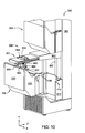
- FIG 10 illustrates a partial perspective view of column 350 and lift system 300 after projection assembly 220 of display unit 355 has been lifted up and extended out by removable lifting mechanism 900, according to the different embodiment of the invention.
- Removable lifting mechanism 900 includes an extension assembly 901, a base assembly 902, lifting straps 903, winder drums 904 and a cranking device 905.
- removable lifting mechanism 900 includes two winder drums 904 that each have two lifting straps attached. In such an embodiment, the four points of attachment provided constrain the rotation of the display unit being lifted, thereby facilitating the safe removal of projection assembly 220 from the display unit of interest.
- having at least two points of connection that are aligned along the z-axis prevent rotation of projection assembly 220 about the x-axis when lifted by removable lifting mechanism 900.
- having at least two points of connection that are aligned along the x-axis prevent rotation of projection assembly 220 about the z-axis when lifted by removable lifting mechanism 900, and the attachment of multiple attachment points in the x-z plane minimizes rotation of projection assembly 220 about the y-axis.
- removable lifting mechanism 900 conveniently removes a projection assembly 220 from a precision frame 210 with little risk of damaging delicate external components of projection assembly 220, such as display panel 230.
- Cranking device 905 is rotated manually or with a motorized actuator to lower lifting straps 903, each of which includes an attachment ring 906. Attachment rings 906 are then coupled to corresponding hooks 907 mounted on projection assembly 220. Hooks 907 may be permanent external features of projection assembly 220 or may be installed temporarily in preparation for the removal of projection assembly 220.
- Cranking device 905 is rotated to raise lifting straps 903 and projection assembly 220, thereby lifting projection assembly 220 and adjustable hanger 720 off of precision fixed pins 710.
- FIG 11 illustrates a perspective view of column 350 and lift system 300 after projection assembly 220 of display unit 355 has been lifted up and extended out by removable lifting mechanism 900, according to the different embodiment of the invention.
- Installation of a projection assembly 220 into precision frame 210 of display unit 355 follows the reverse procedure as outlined above and display units 351-354 are lowered back in place. Because the lifted display units, i.e., display units 351-354, are set onto fixed pins, i.e., pins 702 and precision fixed pins 710, the lifted display units are displaced from their original positions by as little as 50 microns. Thus, no readjustments of the position of the display panel 230 for each of display units 351-354 is necessary. However, if a different projection assembly 220 is installed in display unit 355 than was removed, an addition adjustment procedure is performed so that display panel 230 of the newly installed projection assembly 220 is planar and square with respect to adjacent display panels and the installation gap 705 is suitably narrow. The adjustment procedure involves fine-tuning the position of display panel 230 by rotating adjustment screws 711 to reposition adjustable hangers 720 as desired.
- embodiments of the invention set forth systems for removing a display unit or components thereof from a tiled display wall.
- Advantages of the present invention include the convenient removal of a display unit from a tiled display wall with minimal risk of damaging delicate external components of the display unit.
- Another advantage of the present invention is that display units that have been moved to create adequate clearance for access to another display unit can be quickly and repeatably returned to their original locations without the need for additional position adjustment while maintaining image integrity of the tiled display wall.
Landscapes
- Engineering & Computer Science (AREA)
- Physics & Mathematics (AREA)
- General Physics & Mathematics (AREA)
- Theoretical Computer Science (AREA)
- Multimedia (AREA)
- Mechanical Engineering (AREA)
- Devices For Indicating Variable Information By Combining Individual Elements (AREA)
Description
- This application claims the priority to U.S. Provisional Patent Application filed on January 29, 2010 and having serial number
61/299,914 13/016,851 - Embodiments of the present invention relate generally to multi-panel display systems and, more specifically, to apparatus for removing a display unit from a such systems.
- Electronic display systems are commonly used to display information from computers and other sources. Typical display systems range in size from small displays used in mobile devices to very large displays that are used to display images to thousands of viewers at one time. Tiled display walls provide a large-format environment for presenting large high-resolution images by synchronizing and coupling the output from multiple distinct imaging systems. Such large displays may be created by tiling a plurality of smaller display units together. For example, video walls frequently seen in the electronic media typically use multiple display units, such as flat-panel displays, which are tiled to create such large displays. An issue with tiled displays is that the gap present between the constituent display units can produce a grid pattern visible to the viewer.
-
Figure 1A is a schematic perspective view of a typicaltiled display device 100 having an array ofdisplay units 102 that are each used to display portions of an image to aviewer 108. The array ofdisplay units 102 forms agrid pattern 101 found within a displayedimage 107, which is shown inFigure 1B .Grid pattern 101 may be formed by a frame, bezel, or unilluminated peripheral region circumscribing each of thedisplay units 102, and/or by thegap 103 present betweenadjacent display units 102.Figure 1B is a schematic view oftiled display device 100 inFigure 1 from the perspective ofviewer 108 that further illustrates thegrid pattern 101 that may be visible to the viewer within displayedimage 107. The presence of a noticeable grid pattern indisplay device 100, such asgrid pattern 101, can be distracting forviewer 108. In order for tileddisplay device 100 to produce a uniform display, free ofvisible grid pattern 101, it is important to reduce the width and variation ofgap 103 betweenadjacent display units 102. For example, in many applications, it may be desirable forgap 103 may be on the order of 1 mm or less. -
Display units 102 for a typical tiled display can be relatively bulky, heavy, and include delicate external components, such as the precisely shaped glass panels often used as an image forming surface. As noted above, in a tiled display device the edges of these glass panels may be placed less than a millimeter apart to avoid producinggrid pattern 101. Consequently, removal and replacement of adisplay unit 102 that is damaged or needs service is problematic due to the risk of damagingadditional display units 102 while removing the damaged unit. -
US Pat. 6 704 989 B1 discloses a transportable electronic sign display system and process where electronic display modules are encased in castered protective cases which are broken down on site and assembled in rows of desired length and stackably elevated and maneuvered by a lifting truss. Electronic display modules are lifted from protective case bases with minimal effort or labor. - The article entitled "PMC Structure - 9X Media's Patent-Pending - Modular Scalable, Solid Infrastructure," of 26 January 2010, XP002670539 discloses a portable media center made up of a plurality of display units.
- In view of the foregoing technical challenges and known art, there is a need in the art for a system for removing a display unit from a tiled wall display in an improved fashion relative to prior art devices.
- One embodiment of the present invention sets forth a system for removing a display unit or components thereof from a tiled display wall in a way that minimizes the risk of damaging the removed display unit and other display units in the tiled display wall. To remove a desired display unit, a lifting structure is configured to selectively engage and lift one or more display units away from the desired display unit when the lifting structure is raised by a vertical motion actuator. The lifting structure is further configured to be free to rotate slightly about a vertical axis when lifting the one or more display units, so that the lifted display units are not constrained to purely vertical translation when lifted away from the desired display unit. Instead, the lifted display units are each free to move slightly to either side so that small conflicts or mismatches with adjacent display units do not interfere with the vertical movement of the lifted display units, thereby avoiding damage during the lifting process.
- One advantage of the present invention is that a display unit can be removed from a tiled display wall with minimal risk of damaging delicate external components of the display unit. Another advantage of the present invention is that display units that have been moved to create adequate clearance for access to another display unit can be quickly and repeatably returned to their original locations without the need for additional position adjustment.
- So that the manner in which the above recited features of the present invention can be understood in detail, a more particular description of the invention, briefly summarized above, may be had by reference to embodiments, some of which are illustrated in the appended drawings. It is to be noted, however, that the appended drawings illustrate only typical embodiments of this invention and are therefore not to be considered limiting of its scope, for the invention may admit to other equally effective embodiments.
-
Figure 1A is a schematic perspective view of a typical tiled display device having an array of display units that are each used to display portions of an image to a viewer; -
Figure 1B is a schematic view of the tiled display device inFigure 1A from the perspective of a viewer that further illustrates the grid pattern that may be visible to the viewer within a displayed image; -
Figure 2 illustrates a multi-panel display 200 according to various embodiments of the invention; -
Figure 3 illustrates a lift system for accessing a display unit in a multi-panel display and a plurality of display units that form a column of the multi-panel display inFigure 2 , according to one embodiment of the invention; -
Figure 4 illustrates a perspective view of a lift structure and a support column, according to an embodiment of the invention; -
Figure 5 illustrates a plan view of the lift structure ofFigure 4 with lifting elements arranged in four lifting positions, according to one embodiment of the invention; -
Figure 6 illustrates a perspective view of the lifting structure ofFigure 3 engaged with and lifting a display unit, according to one embodiment of the invention; -
Figure 7 illustrates a partial perspective view of the column of display units and the lift system inFigure 3 as a display unit is lifted to allow access to a lower display unit, according to one embodiment of the invention; -
Figure 8 illustrates a partial perspective view of the column of display units and the lift system inFigure 3 as multiple display units are lifted to allow access to a lower display unit, according to one embodiment of the invention; -
Figure 9 illustrates a partial perspective view of the column of display units and the lift system inFigure 3 after the installation of aremovable lifting mechanism 900, according to a different embodiment of the invention; -
Figure 10 illustrates a partial perspective view of the column of display units and the lift system inFigure 3 after a projection assembly of a display unit has been lifted up and extended out by a removable lifting mechanism, according to the different embodiment of the invention; and -
Figure 11 illustrates a perspective view of the column of display units and the lift system inFigure 3 after a projection assembly of a display unit has been lifted up and extended out by a removable lifting mechanism, according to the different embodiment of the invention. - For clarity, identical reference numbers have been used, where applicable, to designate identical elements that are common between figures. It is contemplated that features of one embodiment may be incorporated in other embodiments without further recitation.
-
Figure 2 illustrates a multi-panel display 200 according to various embodiments of the invention. Multi-panel display 200 includes a plurality ofdisplay units 202 assembled to form adisplay surface 203. In some embodiments,display surface 203 is a planar viewing surface, while in other embodiments,display surface 203 may be curved. For purposes of description, one ofdisplay units 202 inFigure 2 is shown positioned above multi-panel display 200 prior to installation. Multi-panel display 200 is depicted as a six-tile by five-tile array, i.e., six columns of five display units, but any multi-tile display falls within the scope of the invention. In some embodiments, multi-panel display 200 includes abase structure 205 configured to provide stability against tipping and a means for seismic restraint. In such embodiments,base structure 205 is precisely leveled and afirst row 206 ofdisplay units 202 are mechanically coupledthereto base structure 205 so thatfirst row 206 forms a level datum for theremaining display units 202 of multi-panel display 200. - Each
display unit 202 is a light-based electronic display device, such as a laser-phosphor display (LPD), a light-emitting diode (LED) digital light processing (DLP), or an LED-liquid crystal display (LCD) device, and is configured to operate in conjunction with theother display units 202 to produce a single coherent image for a viewer. Eachdisplay unit 202 includes aprecision frame 210, aprojection assembly 220, and adisplay panel 230.Projection assembly 220 is mounted on aprecision frame 210, anddisplay panel 230 is mounted onprojection assembly 220. -
Precision frame 210 is a structural assembly configured to be mechanically coupled toprecision frames 210 of adjacentprecision display units 202 to form a rigid structural truss for multi-panel display 200, according to embodiments of the invention. A precision frame, as defined herein, is a structure having precisely located datum surfaces, projections, and/or other features configured to define the position of the structure when mechanically coupled to another such structure. In some embodiments, eachprecision frame 210 includes two precision pins located on a top surface and mating sockets on a bottom surface to accurately set the vertical pitch between eachdisplay unit 202 and to laterally and rotationally constrain each display unit when positioned on top of another display unit to prevent tilting (rotation about the z-axis), rocking (rotation about the x-axis), and rotation about the y-axis. Examples of such precision pins are described below in conjunction withFigure 7 . In some embodiments, eachprecision frame 210 further includes datum surfaces on each side to further define the lateral position of eachdisplay unit 202, i.e., horizontal pitch. In some embodiments, horizontal latching devices may be employed to further stiffen the structural truss of multi-panel display 200 formed by precision frames 210. Suitable horizontal latching devices that may be used are described in co-pendingU.S. patent application SN 13/013,759 - It is noted that in addition to precision frames 210, no other structure is needed for positioning the plurality of
display panels 230 to produceplanar display surface 203 of multi-panel display 200. This lack of additional support structure is evident inFigure 2 , where onedisplay unit 202 is shown positioned above multi-panel display 200 prior to installation. It is further noted that whileprecision frame 210 is described herein as a separate component of eachdisplay unit 202, in some embodiments of the invention,precision frame 210 may be integral to eachdisplay unit 202. -
Projection assembly 220 includes light sources, optics, and control systems for forming a desired portion of an image ondisplay panel 230, anddisplay panel 230 is the image-forming surface seen by a viewer. For example, whendisplay unit 202 is a laser-phosphor display (LPD),projection assembly 220 includes multiple lasers and associated optics to "paint" different regions of phosphor-containing strips disposed ondisplay panel 230 to produce an image for a viewer, where the optical output energy of each laser paints a different phosphor-containing region of the display. In order to permit a more contiguous image across the assembly, adjacent tiles are positioned as close as practicable to each other. Consequently,display panel 230 is a fragile and precisely shaped glass sheet that will be positioned as closely as practicable to and aligned with adjacent display panels to minimize a grid pattern onplanar display surface 203 visible to a viewer. -
Figure 3 illustrates alift system 300 for accessing a display unit in multi-panel display 200 and a plurality of display units 351-355 that form acolumn 350 of multi-panel display 200 inFigure 2 , according to one embodiment of the invention.Lift system 300 includes alift structure 301, asupport column 302 disposed insidelift structure 301, a liftsystem support frame 310, and a vertical motion actuator 500 (shown inFigure 5 ). Alternatively,support column 302 may be a rail situated adjacent to liftstructure 301.Column 350 can be any column ofdisplay units 202 contained in multi-panel display 200 and includes display units 351-355. Structural details and alignment features of display units 351-355 are described below in conjunction withFigure 7 . - Lift
system support frame 310 includessupport columns 303 and atop piece 304. Liftsystem support frame 310 serves as an independent structural support system forlift system 300 and is coupled to supportcolumn 302 viatop piece 304. In addition,support frame 303 and/or structures mounted thereon can be configured as a vertical rail system that keepsdisplay units 202 aligned as desired during the lifting process. Because liftsystem support frame 310 is structurally independent fromcolumn 350,lift system 300 can be repositioned adjacent to anycolumn 350 in multi-panel display 200 that has adisplay unit 202 in need of removal or service. Alternatively, onelift system 300 may be installed behind eachcolumn 350 making up multi-panel display 200. -
Lift structure 301 is used to lift one or more of the display units ofcolumn 350 and thereby facilitate access to one of display units 351-355 for removal or repair.Lift structure 301 is a lifting mechanism configured to selectively engage and lift one or more of display units 351-354 when the lifting structure is raised byvertical motion actuator 500.Lift structure 301 is further configured to be free to rotate slightly about a vertical axis when lifting the one or more display units so that the lifted display units are not constrained to purely vertical translation when being lifted. For example, lifted display units may be free to rotate approximately ±10 degrees about a vertical axis during the lifting process before being constrained rotationally bysupport frame 303 and/or structures mounted thereon. In some embodiments,lift structure 301 rotates aboutsupport column 302, which may be disposed coaxially insidelift structure 301. In addition, during the lifting process, display units 351-354 are each engaged and lifted by a single lifting member and therefore are relatively unconstrained, i.e., are not rigidly held, while translating vertically. Thus, display units 351-355 that are being lifted bylift structure 301 can move slightly to either side so that small conflicts or mismatches with adjacent tiles do not interfere with the upward or downward movement of the lifted display units, thereby avoiding damage to displaypanels 230 ofdisplay units 202 during the lifting process. -
Figure 4 illustrates a perspective view oflift structure 301 andsupport column 302, according to an embodiment of the invention. As shown,lift structure 301 includes a plurality of liftingmembers 305 arranged in multiple lift position groups 1-4, where each of these lift position groups: 1) corresponds to a particular lift position of lift structured 301; 2) is made up of vertically aligned liftingmembers 305; and 3) is radially offset on liftingstructure 301 from the other lift positions. In addition, each of lift position groups 1-4 includes a unique combination of liftingmembers 305 configured to engage and lift a unique combination ofdisplay units 202. Thus, whenlift structure 301 is rotated to a lift position 1, lift position group 1 is positioned to engage andlift display unit 351 with asingle lifting member 305 whenlift structure 301 is raised byvertical motion actuator 500. Similarly, whenlift structure 301 is rotated to alift position 2, the two liftingmembers 305 oflift position group 2 are positioned to engage and liftdisplay units lift structure 301 is rotated to alift position 3, liftposition group 3 is positioned to engage and lift display units 351-353; and whenlift structure 301 is rotated to a lift position four, liftposition group 4 is positioned to engage and lift display units 351-354 . The relative radial positions of lift positions 1-4 are illustrated more clearly inFigure 5 . -
Figure 5 illustrates a plan view oflift structure 301 with liftingelements 305 arranged in four lifting positions, according to one embodiment of the invention. As shown, lifting positions groups 1-4 are each positioned at a different radial location on liftingstructure 301.Support column 302 is disposed inlift structure 301 to serve as a support structure forlift structure 301 and to provide a vertical track along which liftstructure 301 translates when lifted and lowered byvertical motion actuator 500.Vertical motion actuator 500 raises and lowerslift structure 301 and may be any linear actuator known in the art, such as a pneumatic actuator or a lead-screw-based actuator. InFigure 5 ,vertical motion actuator 500 is depicted insidesupport column 302. In other embodiments,vertical motion actuator 500 may be located adjacent to liftstructure 301 andoutside support column 302. When selecting a particular lift position,lift structure 301 may be rotated manually or by means of a motorized or otherwise powered actuator. - When installed in multi-panel display 200,
display panels 230 ofdisplay units 202 are closely positioned, i.e., they have a separation on the order of about 1 mm or less. Becauselift structure 301 is configured to allow slight movement of display units 351-355 such a small gap is likely to result in damage to displaypanels 230 during the lifting process. In some embodiments, liftingelements 305 oflift structure 301 are configured to minimize contact between vertically adjacent display units 351-355 during the lifting and lowering process to prevent such damage. In such embodiments, liftingelements 305 in one lift position group are configured to sequentially engage and lift the desired display units incolumn 350 starting with the topmost display unit, i.e.,display unit 351, and lifting and engaging progressively lower display units once a desired gap has formed between the lifted display unit and the next display unit to be lifted. Specifically, the separation between liftingelements 305 in a particular lift position group is non-uniform and increases betweenlower lifting elements 305 in the lift position group. The non-uniform and increasing separation between liftingelements 305 in one lift position group is illustrated inFigure 4 . - Referring to lift
position group 4 inFigure 4 , liftingelement 305A is positioned to engage and lift the top display unit incolumn 350 during the lifting process, i.e.,display unit 351. Similarly, liftingelement 305B is positioned to engage andlift display unit 352, liftingelement 305C is positioned to engage andlift display unit 353, and liftingelement 305D is positioned to engage andlift display unit 354. Accordingly,separation 401 between liftingelement 305A and liftingelement 305B is equal to the height ofdisplay unit 351 plus the height of the gap desired betweendisplay unit 351 anddisplay unit 352 during the lifting process. Thus,display unit 352 is not engaged and lifted until a desired gap betweendisplay units Separation 402 between liftingelement 305B and liftingelement 305C is equal to the height ofdisplay unit 352 plus the height of the gap desired betweendisplay unit 351 anddisplay unit 352 during the lifting process and the height of the gap desired betweendisplay unit separation 402 to be greater thanseparation 401 by the gap desired betweendisplay units display unit 353 is not engaged and lifted until the desired gap betweendisplay units separation 403 is configured to be greater thanseparation 402 by the gap desired betweendisplay units - In operation,
lift system 300 lifts one or more of display units 351-354 vialift structure 301 to facilitate access to one of display units 351-355 for removal or repair. For example, in order to access and/or removedisplay unit 355, all of display units 351-355, must be raised. Thus,lift structure 301 is rotated to liftposition 4 so that liftingelements 305A-305D are positioned to engage and lift display units 351-354.Figure 6 illustrates a perspective view of liftingstructure 301 engaged with and lifting a display unit, according to one embodiment of the invention. Aslift structure 301 is raised, liftingelement 305 engages amating hook 601 disposed on arear surface 361 ofprecision frame 210 ofdisplay unit 351, thereby liftingdisplay unit 351 off ofdisplay unit 352. For clarity,support column 303 has been omitted fromFigure 6 . In practice,support column 303 and/or structures mounted thereon can be configured as a vertical rail system that keepsdisplay unit 351 aligned as desired during the lifting process by contacting one or more rear surfaces 361-363 ofdisplay unit 351. -
Figure 7 illustrates a partial perspective view ofcolumn 350 andlift system 300 inFigure 3 asdisplay unit 351 is lifted to allow access to a lower display unit, according to one embodiment of the invention. InFigure 7 , lift structure 301 (not shown for clarity) is engaged with and has lifteddisplay unit 351 to form alifting gap 701 betweendisplay unit 351 anddisplay unit 352. In so doing,lift structure 301 has lifteddisplay unit 351 off of two precisely placedpins 702 disposed on a top surface of theprecision frame 210 ofdisplay unit 352. Prior to lifting, pins 702 are seated inmating sockets 703 disposed on the underside of theprecision frame 210 ofdisplay unit 351.Pins 702 andmating sockets 703 are also disposed on the remaining display units ofcolumn 350 to accurately set the vertical pitch between each of display units 351-355 and to laterally and rotationally constrain the display units ofcolumn 350 when installed in multi-panel display 200. - It is noted that in
Figure 7 ,installation gap 705, which is minimized to reduce a visible grid pattern, is still present betweendisplay units lift structure 301 and are still resting on the display unit of concern, i.e., the display unit to be accessed and/or removed. The position of eachdisplay panel 230 can be fine-tuned with respect toadjacent display panels 230 in multi-panel display 200 so thatinstallation gap 705 is uniform arounddisplay panel 230 anddisplay panel 230 is planar and square withadjacent display panels 230. In some embodiments,projection assembly 220 of each display panel is hung onto a precision fixedpin 710 disposed on two or more interior surfaces ofprecision frame 210. In such embodiments,projection assembly 220 includes an adjustable hanger 720 (shown inFigure 10 ) that can be adjusted vertically (along the y-axis) and horizontally (along the z-axis) using adjustment screws 711. Because the fine-tuned position of display units 351-355 in multi-panel display 200 relies on adjustable hangers and precision pins, these display units retain the original relative position with respect to adjacent display units when lowered back into place, and no addition position adjustment is required after being raised and lowered bylift system 300. -
Figure 8 illustrates a partial perspective view ofcolumn 350 andlift system 300 as display units 351-354 are lifted to allow access to a lower display unit, according to one embodiment of the invention. As shown,lift structure 301 has lifted display units 351-354 away fromdisplay unit 355 so thatdisplay unit 355 may be accessed and/or removed for service, replacement, etc.Display units gap 701 anddisplay units gap 701. Consequently, pins 702 are not mated withmating sockets 703 and display units 351-354 are free to move independently of each other during the lifting process. -
Figure 9 illustrates a partial perspective view ofcolumn 350 andremoval system 300 after the installation of aremovable lifting mechanism 900, according to a different embodiment of the invention. Once sufficient clearance has been attained above the display unit of concern, which inFigure 9 isdisplay unit 355,removable lifting mechanism 900 is mechanically coupled to supportcolumns 303 so thatprojection assembly 220 ofdisplay unit 355 can be removed from multi-panel display 200. In some embodiments,removable lifting mechanism 900 is bolted or clamped on to supportcolumns 303. In other embodiments, a latch mechanism or shelf is disposed onsupport columns 303 and/orsupport column 302 to facilitate attachment ofremovable lifting mechanism 900. In yet other embodiments,removable lifting mechanism 900 is temporarily attached to supportcolumn 302. -
Figure 10 illustrates a partial perspective view ofcolumn 350 andlift system 300 afterprojection assembly 220 ofdisplay unit 355 has been lifted up and extended out byremovable lifting mechanism 900, according to the different embodiment of the invention.Removable lifting mechanism 900 includes anextension assembly 901, abase assembly 902, liftingstraps 903, winder drums 904 and a crankingdevice 905. In some embodiments,removable lifting mechanism 900 includes twowinder drums 904 that each have two lifting straps attached. In such an embodiment, the four points of attachment provided constrain the rotation of the display unit being lifted, thereby facilitating the safe removal ofprojection assembly 220 from the display unit of interest. Specifically, having at least two points of connection that are aligned along the z-axis prevent rotation ofprojection assembly 220 about the x-axis when lifted byremovable lifting mechanism 900. Similarly, having at least two points of connection that are aligned along the x-axis prevent rotation ofprojection assembly 220 about the z-axis when lifted byremovable lifting mechanism 900, and the attachment of multiple attachment points in the x-z plane minimizes rotation ofprojection assembly 220 about the y-axis. - In operation,
removable lifting mechanism 900 conveniently removes aprojection assembly 220 from aprecision frame 210 with little risk of damaging delicate external components ofprojection assembly 220, such asdisplay panel 230. Crankingdevice 905 is rotated manually or with a motorized actuator to lower liftingstraps 903, each of which includes anattachment ring 906. Attachment rings 906 are then coupled to correspondinghooks 907 mounted onprojection assembly 220.Hooks 907 may be permanent external features ofprojection assembly 220 or may be installed temporarily in preparation for the removal ofprojection assembly 220. Crankingdevice 905 is rotated to raise liftingstraps 903 andprojection assembly 220, thereby liftingprojection assembly 220 andadjustable hanger 720 off of precision fixed pins 710. Once crankingdevice 905 has raisedprojection assembly 220 to a level with suitable clearance,extension assembly 901 can be extended frombase assembly 902 to complete removal ofprojection assembly 220 from multi-panel display 200.Figure 11 illustrates a perspective view ofcolumn 350 andlift system 300 afterprojection assembly 220 ofdisplay unit 355 has been lifted up and extended out byremovable lifting mechanism 900, according to the different embodiment of the invention. - Installation of a
projection assembly 220 intoprecision frame 210 ofdisplay unit 355 follows the reverse procedure as outlined above and display units 351-354 are lowered back in place. Because the lifted display units, i.e., display units 351-354, are set onto fixed pins, i.e., pins 702 and precision fixedpins 710, the lifted display units are displaced from their original positions by as little as 50 microns. Thus, no readjustments of the position of thedisplay panel 230 for each of display units 351-354 is necessary. However, if adifferent projection assembly 220 is installed indisplay unit 355 than was removed, an addition adjustment procedure is performed so thatdisplay panel 230 of the newly installedprojection assembly 220 is planar and square with respect to adjacent display panels and theinstallation gap 705 is suitably narrow. The adjustment procedure involves fine-tuning the position ofdisplay panel 230 by rotating adjustment screws 711 to repositionadjustable hangers 720 as desired. - In sum, embodiments of the invention set forth systems for removing a display unit or components thereof from a tiled display wall. Advantages of the present invention include the convenient removal of a display unit from a tiled display wall with minimal risk of damaging delicate external components of the display unit. Another advantage of the present invention is that display units that have been moved to create adequate clearance for access to another display unit can be quickly and repeatably returned to their original locations without the need for additional position adjustment while maintaining image integrity of the tiled display wall.
- While the foregoing is directed to embodiments of the present invention, other and further embodiments of the invention may be devised without departing from the basic scope thereof, and the scope thereof is determined by the claims that follow.
Claims (14)
- A system (300) for removing a display unit from a multi-display-unit assembly, the system comprising:a vertical motion actuator (500); anda lift structure (301) coupled to the vertical motion actuator (500) and configured to selectively engage and lift one or more display units (351-355) when the lift structure is raised by the vertical motion actuator and to rotate a constrained amount about a vertical axis when lifting the one or more display units,wherein the lift structure (301) includes a plurality of lifting members (305) arranged along a vertical column, each lifting member having an associated lift position, so that each of the one or more display units (351-355) is engaged by and lifted with a different lifting member when the lift structure is raised by the vertical motion actuator (500).
- The system of claim 1, wherein each display unit (351-355) includes a precision frame (210) configured to couple to a vertically adjacent display unit.
- The system of claim 1, wherein each display unit (351-355) further includes a display surface (203), and the multi-display-unit assembly (200) is configured to have a substantially uniform gap between each display unit that is less than about 2 mm.
- The system of claim 3, wherein each display unit (351-355) further includes fixed pins (710) positioned on the precision frame and a projection assembly (220) having adjustable hangers (720) that are configured to engage the fixed pins and adjust the position of the projection assembly with respect to adjacent projection assemblies of adjacent display units.
- The system of claim 3, wherein the multi-display-unit assembly (200) is configured to have a substantially uniform gap between each display unit that is greater than about 0.5 mm.
- The system of claim 1, wherein the lift structure (301) is structurally independent from the multi-display-unit assembly (200).
- The system of claim 1, wherein the lift structure (301) is configured to provide access to any display unit (351-355) from any column of display units in the multi-display-unit assembly (200).
- The system of claim 1, wherein the lift structure (301) is fixed in place for providing access to a display unit (351-355) from a single column of display units in the multi-display-unit assembly (200).
- The system of claim 1, wherein the lifting members (305) are vertically aligned when lifting members are located at the associated lift position.
- The system of claim 1, wherein the lifting members (305) are organized into subgroups (305A-305D) and the lift position associated with each subgroup of lifting members is radially offset on the vertical column from the lift position associated with each of the other subgroups of lifting members.
- The system of claim 10, wherein each subgroup of lifting members (305A-305D) is selected sequentially by rotating the vertical column to different radial orientation when the lift structure (301) is disengaged from the one or more display units (351-355).
- The system of claim 1, wherein each unique combination of lift positions enables the lifting members (305) to engage and lift a unique combination of display units (351-355).
- The system of claim 1, wherein the lifting members (305) are organized into subgroups (305A-305D) and the lifting members in each subgroup are configured to sequentially lift one or more display units (351-355) that are aligned vertically in the multi-display-unit assembly (200) starting from the top display unit and followed by each progressively lower display unit.
- The system of claim 13, wherein the vertical separation between the lifting member that lifts a first display unit and the lifting member that lifts a second display unit that is vertically adjacent to and below the first display unit is less than the vertical separation between the lifting member that lifts the second display unit and the lifting member that lifts a third display unit that is vertically adjacent to and below the second display unit.
Applications Claiming Priority (2)
| Application Number | Priority Date | Filing Date | Title |
|---|---|---|---|
| US29991410P | 2010-01-29 | 2010-01-29 | |
| US13/016,851 US8801357B2 (en) | 2010-01-29 | 2011-01-28 | System for removing a display unit from a multi panel display |
Publications (3)
| Publication Number | Publication Date |
|---|---|
| EP2355075A2 EP2355075A2 (en) | 2011-08-10 |
| EP2355075A3 EP2355075A3 (en) | 2012-04-25 |
| EP2355075B1 true EP2355075B1 (en) | 2013-05-29 |
Family
ID=44341839
Family Applications (1)
| Application Number | Title | Priority Date | Filing Date |
|---|---|---|---|
| EP11152749.5A Not-in-force EP2355075B1 (en) | 2010-01-29 | 2011-01-31 | System for removing a display unit from a multi panel display |
Country Status (2)
| Country | Link |
|---|---|
| US (1) | US8801357B2 (en) |
| EP (1) | EP2355075B1 (en) |
Families Citing this family (17)
| Publication number | Priority date | Publication date | Assignee | Title |
|---|---|---|---|---|
| US8974077B2 (en) | 2012-07-30 | 2015-03-10 | Ultravision Technologies, Llc | Heat sink for LED light source |
| WO2014118644A2 (en) * | 2013-01-29 | 2014-08-07 | Wells Fargo India Solutions Private Limited | Banking services experience center |
| US20140239139A1 (en) * | 2013-02-28 | 2014-08-28 | Tait Technologies Bvba | Video display system and method for assembling |
| US9047791B2 (en) | 2013-03-16 | 2015-06-02 | Adti Media, Llc. | Sign construction with sectional sign assemblies and installation kit and method of using same |
| US9761157B2 (en) | 2013-03-16 | 2017-09-12 | Adti Media Llc | Customized sectional sign assembly kit and method of using kit for construction and installation of same |
| US9666105B2 (en) | 2013-03-16 | 2017-05-30 | ADTI Media, LLC | Sign construction with modular wire harness arrangements and methods of using same for backside to frontside power and data distribution schemes |
| US8929083B2 (en) | 2013-03-16 | 2015-01-06 | ADIT Media, LLC | Compound structural frame and method of using same for efficient retrofitting |
| US8824125B1 (en) | 2013-03-16 | 2014-09-02 | ADTI Media, LLC | Modular installation and conversion kit for electronic sign structure and method of using same |
| US9852666B2 (en) | 2013-03-16 | 2017-12-26 | Adti Media Llc | Full height sectional sign assembly and installation kit and method of using same |
| US9195281B2 (en) | 2013-12-31 | 2015-11-24 | Ultravision Technologies, Llc | System and method for a modular multi-panel display |
| US9582237B2 (en) | 2013-12-31 | 2017-02-28 | Ultravision Technologies, Llc | Modular display panels with different pitches |
| US20150187237A1 (en) | 2013-12-31 | 2015-07-02 | Ultravision Holdings, Llc | System and Method for a Modular Multi-Panel Display |
| US10706770B2 (en) | 2014-07-16 | 2020-07-07 | Ultravision Technologies, Llc | Display system having module display panel with circuitry for bidirectional communication |
| CN111986569B (en) * | 2019-05-22 | 2024-03-29 | 半径数码展示公司 | polymorphic image display |
| CN114859591B (en) * | 2021-02-05 | 2023-11-21 | 北京京东方光电科技有限公司 | Display module, display system and control method of display system |
| BE1030171B1 (en) * | 2022-01-11 | 2023-08-10 | Twenty Three Bvba | TRANSPORT MODULE FOR HANDLING LED MODULES FOR BUILDING A LED WALL |
| US11862051B2 (en) * | 2022-03-02 | 2024-01-02 | Tcl China Star Optoelectronics Technology Co., Ltd. | Display panel and light board |
Family Cites Families (7)
| Publication number | Priority date | Publication date | Assignee | Title |
|---|---|---|---|---|
| US3042372A (en) * | 1960-05-27 | 1962-07-03 | Gen Motors Corp | Powered jack screw assembly |
| US4546891A (en) | 1983-02-24 | 1985-10-15 | Mi-Jack Products, Inc. | Grappler system for lifting apparatus |
| US5570990A (en) * | 1993-11-05 | 1996-11-05 | Asyst Technologies, Inc. | Human guided mobile loader stocker |
| NL1006461C2 (en) * | 1997-07-03 | 1999-01-05 | Asm Int | Storage assembly for wafers. |
| US6099234A (en) * | 1999-01-14 | 2000-08-08 | Mason; Milford K. | Tractor-mounted forklift |
| US6704989B1 (en) | 2001-12-19 | 2004-03-16 | Daktronics, Inc. | Process for assembling and transporting an electronic sign display system |
| US7774968B2 (en) | 2007-04-27 | 2010-08-17 | Daktronics, Inc. | Transportable electronic sign display system |
-
2011
- 2011-01-28 US US13/016,851 patent/US8801357B2/en active Active
- 2011-01-31 EP EP11152749.5A patent/EP2355075B1/en not_active Not-in-force
Also Published As
| Publication number | Publication date |
|---|---|
| EP2355075A2 (en) | 2011-08-10 |
| US20110188981A1 (en) | 2011-08-04 |
| EP2355075A3 (en) | 2012-04-25 |
| US8801357B2 (en) | 2014-08-12 |
Similar Documents
| Publication | Publication Date | Title |
|---|---|---|
| EP2355075B1 (en) | System for removing a display unit from a multi panel display | |
| US11741859B2 (en) | Modular display system and methods | |
| KR100898682B1 (en) | Multi-Vision Universal Cradle | |
| US9854701B2 (en) | Multivision display system | |
| US20180330651A1 (en) | Inspection apparatus | |
| US11922833B2 (en) | System and method for mounting of a polygonal display wall | |
| KR20100055040A (en) | Universal stand for multi vision | |
| US10356396B2 (en) | Exhibition device and video picture exhibition method | |
| CN102721692A (en) | Detecting device for glass substrate cassette | |
| KR102288837B1 (en) | Apparatus for inspecting curved display panel | |
| CN203336166U (en) | Mounting rack of display device and display system | |
| KR100722163B1 (en) | PCB inspection device | |
| JP2010258269A (en) | High density substrate storage device | |
| TW202338760A (en) | Frame, display device, and installation method for display device | |
| JPS63275996A (en) | Apparatus for inspecting appearance of fuel assembly | |
| JP4084653B2 (en) | 2D measuring machine | |
| CN108205213B (en) | A laser output shape control system and method for repairing color filter substrates | |
| JP5495313B2 (en) | Chuck device, substrate observation device, and defect correction device | |
| CN219300385U (en) | Display screen support frame | |
| KR102465473B1 (en) | Display device | |
| CN221632520U (en) | Chip concatenation counterpoint device | |
| US20250240905A1 (en) | Support structure with improved alignment for frames of a tiled display wall | |
| US20070234607A1 (en) | Continuously displaying frame for animation | |
| KR20240178849A (en) | Lift pin assembly and apparatus for processing substrate having the same | |
| KR100521995B1 (en) | Apparatus for loading a cassette |
Legal Events
| Date | Code | Title | Description |
|---|---|---|---|
| PUAI | Public reference made under article 153(3) epc to a published international application that has entered the european phase |
Free format text: ORIGINAL CODE: 0009012 |
|
| AK | Designated contracting states |
Kind code of ref document: A2 Designated state(s): AL AT BE BG CH CY CZ DE DK EE ES FI FR GB GR HR HU IE IS IT LI LT LU LV MC MK MT NL NO PL PT RO RS SE SI SK SM TR |
|
| AX | Request for extension of the european patent |
Extension state: BA ME |
|
| PUAL | Search report despatched |
Free format text: ORIGINAL CODE: 0009013 |
|
| RIC1 | Information provided on ipc code assigned before grant |
Ipc: B65G 57/30 20060101ALI20120301BHEP Ipc: G09F 9/33 20060101AFI20120301BHEP |
|
| RIC1 | Information provided on ipc code assigned before grant |
Ipc: B65G 57/30 20060101ALI20120315BHEP Ipc: G09F 9/33 20060101AFI20120315BHEP |
|
| AK | Designated contracting states |
Kind code of ref document: A3 Designated state(s): AL AT BE BG CH CY CZ DE DK EE ES FI FR GB GR HR HU IE IS IT LI LT LU LV MC MK MT NL NO PL PT RO RS SE SI SK SM TR |
|
| AX | Request for extension of the european patent |
Extension state: BA ME |
|
| 17P | Request for examination filed |
Effective date: 20120813 |
|
| 17Q | First examination report despatched |
Effective date: 20120906 |
|
| GRAP | Despatch of communication of intention to grant a patent |
Free format text: ORIGINAL CODE: EPIDOSNIGR1 |
|
| RIC1 | Information provided on ipc code assigned before grant |
Ipc: G09F 9/33 20060101AFI20121130BHEP |
|
| GRAS | Grant fee paid |
Free format text: ORIGINAL CODE: EPIDOSNIGR3 |
|
| GRAA | (expected) grant |
Free format text: ORIGINAL CODE: 0009210 |
|
| AK | Designated contracting states |
Kind code of ref document: B1 Designated state(s): AL AT BE BG CH CY CZ DE DK EE ES FI FR GB GR HR HU IE IS IT LI LT LU LV MC MK MT NL NO PL PT RO RS SE SI SK SM TR |
|
| REG | Reference to a national code |
Ref country code: GB Ref legal event code: FG4D |
|
| REG | Reference to a national code |
Ref country code: CH Ref legal event code: EP |
|
| REG | Reference to a national code |
Ref country code: AT Ref legal event code: REF Ref document number: 614833 Country of ref document: AT Kind code of ref document: T Effective date: 20130615 |
|
| REG | Reference to a national code |
Ref country code: IE Ref legal event code: FG4D |
|
| REG | Reference to a national code |
Ref country code: DE Ref legal event code: R096 Ref document number: 602011001768 Country of ref document: DE Effective date: 20130725 |
|
| REG | Reference to a national code |
Ref country code: AT Ref legal event code: MK05 Ref document number: 614833 Country of ref document: AT Kind code of ref document: T Effective date: 20130529 |
|
| REG | Reference to a national code |
Ref country code: LT Ref legal event code: MG4D |
|
| PG25 | Lapsed in a contracting state [announced via postgrant information from national office to epo] |
Ref country code: PT Free format text: LAPSE BECAUSE OF FAILURE TO SUBMIT A TRANSLATION OF THE DESCRIPTION OR TO PAY THE FEE WITHIN THE PRESCRIBED TIME-LIMIT Effective date: 20130930 Ref country code: AT Free format text: LAPSE BECAUSE OF FAILURE TO SUBMIT A TRANSLATION OF THE DESCRIPTION OR TO PAY THE FEE WITHIN THE PRESCRIBED TIME-LIMIT Effective date: 20130529 Ref country code: SE Free format text: LAPSE BECAUSE OF FAILURE TO SUBMIT A TRANSLATION OF THE DESCRIPTION OR TO PAY THE FEE WITHIN THE PRESCRIBED TIME-LIMIT Effective date: 20130529 Ref country code: IS Free format text: LAPSE BECAUSE OF FAILURE TO SUBMIT A TRANSLATION OF THE DESCRIPTION OR TO PAY THE FEE WITHIN THE PRESCRIBED TIME-LIMIT Effective date: 20130929 Ref country code: LT Free format text: LAPSE BECAUSE OF FAILURE TO SUBMIT A TRANSLATION OF THE DESCRIPTION OR TO PAY THE FEE WITHIN THE PRESCRIBED TIME-LIMIT Effective date: 20130529 Ref country code: SI Free format text: LAPSE BECAUSE OF FAILURE TO SUBMIT A TRANSLATION OF THE DESCRIPTION OR TO PAY THE FEE WITHIN THE PRESCRIBED TIME-LIMIT Effective date: 20130529 Ref country code: GR Free format text: LAPSE BECAUSE OF FAILURE TO SUBMIT A TRANSLATION OF THE DESCRIPTION OR TO PAY THE FEE WITHIN THE PRESCRIBED TIME-LIMIT Effective date: 20130830 Ref country code: ES Free format text: LAPSE BECAUSE OF FAILURE TO SUBMIT A TRANSLATION OF THE DESCRIPTION OR TO PAY THE FEE WITHIN THE PRESCRIBED TIME-LIMIT Effective date: 20130909 Ref country code: FI Free format text: LAPSE BECAUSE OF FAILURE TO SUBMIT A TRANSLATION OF THE DESCRIPTION OR TO PAY THE FEE WITHIN THE PRESCRIBED TIME-LIMIT Effective date: 20130529 Ref country code: NO Free format text: LAPSE BECAUSE OF FAILURE TO SUBMIT A TRANSLATION OF THE DESCRIPTION OR TO PAY THE FEE WITHIN THE PRESCRIBED TIME-LIMIT Effective date: 20130829 |
|
| REG | Reference to a national code |
Ref country code: NL Ref legal event code: VDEP Effective date: 20130529 |
|
| PG25 | Lapsed in a contracting state [announced via postgrant information from national office to epo] |
Ref country code: HR Free format text: LAPSE BECAUSE OF FAILURE TO SUBMIT A TRANSLATION OF THE DESCRIPTION OR TO PAY THE FEE WITHIN THE PRESCRIBED TIME-LIMIT Effective date: 20130529 Ref country code: PL Free format text: LAPSE BECAUSE OF FAILURE TO SUBMIT A TRANSLATION OF THE DESCRIPTION OR TO PAY THE FEE WITHIN THE PRESCRIBED TIME-LIMIT Effective date: 20130529 Ref country code: BG Free format text: LAPSE BECAUSE OF FAILURE TO SUBMIT A TRANSLATION OF THE DESCRIPTION OR TO PAY THE FEE WITHIN THE PRESCRIBED TIME-LIMIT Effective date: 20130829 Ref country code: RS Free format text: LAPSE BECAUSE OF FAILURE TO SUBMIT A TRANSLATION OF THE DESCRIPTION OR TO PAY THE FEE WITHIN THE PRESCRIBED TIME-LIMIT Effective date: 20130529 |
|
| PG25 | Lapsed in a contracting state [announced via postgrant information from national office to epo] |
Ref country code: LV Free format text: LAPSE BECAUSE OF FAILURE TO SUBMIT A TRANSLATION OF THE DESCRIPTION OR TO PAY THE FEE WITHIN THE PRESCRIBED TIME-LIMIT Effective date: 20130529 |
|
| PG25 | Lapsed in a contracting state [announced via postgrant information from national office to epo] |
Ref country code: EE Free format text: LAPSE BECAUSE OF FAILURE TO SUBMIT A TRANSLATION OF THE DESCRIPTION OR TO PAY THE FEE WITHIN THE PRESCRIBED TIME-LIMIT Effective date: 20130529 Ref country code: BE Free format text: LAPSE BECAUSE OF FAILURE TO SUBMIT A TRANSLATION OF THE DESCRIPTION OR TO PAY THE FEE WITHIN THE PRESCRIBED TIME-LIMIT Effective date: 20130529 Ref country code: DK Free format text: LAPSE BECAUSE OF FAILURE TO SUBMIT A TRANSLATION OF THE DESCRIPTION OR TO PAY THE FEE WITHIN THE PRESCRIBED TIME-LIMIT Effective date: 20130529 Ref country code: SK Free format text: LAPSE BECAUSE OF FAILURE TO SUBMIT A TRANSLATION OF THE DESCRIPTION OR TO PAY THE FEE WITHIN THE PRESCRIBED TIME-LIMIT Effective date: 20130529 Ref country code: CZ Free format text: LAPSE BECAUSE OF FAILURE TO SUBMIT A TRANSLATION OF THE DESCRIPTION OR TO PAY THE FEE WITHIN THE PRESCRIBED TIME-LIMIT Effective date: 20130529 |
|
| PG25 | Lapsed in a contracting state [announced via postgrant information from national office to epo] |
Ref country code: RO Free format text: LAPSE BECAUSE OF FAILURE TO SUBMIT A TRANSLATION OF THE DESCRIPTION OR TO PAY THE FEE WITHIN THE PRESCRIBED TIME-LIMIT Effective date: 20130529 Ref country code: IT Free format text: LAPSE BECAUSE OF FAILURE TO SUBMIT A TRANSLATION OF THE DESCRIPTION OR TO PAY THE FEE WITHIN THE PRESCRIBED TIME-LIMIT Effective date: 20130529 Ref country code: NL Free format text: LAPSE BECAUSE OF FAILURE TO SUBMIT A TRANSLATION OF THE DESCRIPTION OR TO PAY THE FEE WITHIN THE PRESCRIBED TIME-LIMIT Effective date: 20130529 |
|
| PLBE | No opposition filed within time limit |
Free format text: ORIGINAL CODE: 0009261 |
|
| STAA | Information on the status of an ep patent application or granted ep patent |
Free format text: STATUS: NO OPPOSITION FILED WITHIN TIME LIMIT |
|
| 26N | No opposition filed |
Effective date: 20140303 |
|
| REG | Reference to a national code |
Ref country code: DE Ref legal event code: R097 Ref document number: 602011001768 Country of ref document: DE Effective date: 20140303 |
|
| REG | Reference to a national code |
Ref country code: DE Ref legal event code: R119 Ref document number: 602011001768 Country of ref document: DE |
|
| PG25 | Lapsed in a contracting state [announced via postgrant information from national office to epo] |
Ref country code: LU Free format text: LAPSE BECAUSE OF FAILURE TO SUBMIT A TRANSLATION OF THE DESCRIPTION OR TO PAY THE FEE WITHIN THE PRESCRIBED TIME-LIMIT Effective date: 20140131 |
|
| REG | Reference to a national code |
Ref country code: CH Ref legal event code: PL |
|
| REG | Reference to a national code |
Ref country code: DE Ref legal event code: R119 Ref document number: 602011001768 Country of ref document: DE Effective date: 20140801 |
|
| PG25 | Lapsed in a contracting state [announced via postgrant information from national office to epo] |
Ref country code: LI Free format text: LAPSE BECAUSE OF NON-PAYMENT OF DUE FEES Effective date: 20140131 Ref country code: DE Free format text: LAPSE BECAUSE OF NON-PAYMENT OF DUE FEES Effective date: 20140801 Ref country code: CH Free format text: LAPSE BECAUSE OF NON-PAYMENT OF DUE FEES Effective date: 20140131 |
|
| REG | Reference to a national code |
Ref country code: FR Ref legal event code: ST Effective date: 20140930 |
|
| REG | Reference to a national code |
Ref country code: IE Ref legal event code: MM4A |
|
| PG25 | Lapsed in a contracting state [announced via postgrant information from national office to epo] |
Ref country code: FR Free format text: LAPSE BECAUSE OF NON-PAYMENT OF DUE FEES Effective date: 20140131 |
|
| PG25 | Lapsed in a contracting state [announced via postgrant information from national office to epo] |
Ref country code: IE Free format text: LAPSE BECAUSE OF NON-PAYMENT OF DUE FEES Effective date: 20140131 |
|
| PG25 | Lapsed in a contracting state [announced via postgrant information from national office to epo] |
Ref country code: MC Free format text: LAPSE BECAUSE OF FAILURE TO SUBMIT A TRANSLATION OF THE DESCRIPTION OR TO PAY THE FEE WITHIN THE PRESCRIBED TIME-LIMIT Effective date: 20130529 |
|
| PG25 | Lapsed in a contracting state [announced via postgrant information from national office to epo] |
Ref country code: MT Free format text: LAPSE BECAUSE OF FAILURE TO SUBMIT A TRANSLATION OF THE DESCRIPTION OR TO PAY THE FEE WITHIN THE PRESCRIBED TIME-LIMIT Effective date: 20130529 |
|
| PG25 | Lapsed in a contracting state [announced via postgrant information from national office to epo] |
Ref country code: SM Free format text: LAPSE BECAUSE OF FAILURE TO SUBMIT A TRANSLATION OF THE DESCRIPTION OR TO PAY THE FEE WITHIN THE PRESCRIBED TIME-LIMIT Effective date: 20130529 |
|
| PG25 | Lapsed in a contracting state [announced via postgrant information from national office to epo] |
Ref country code: CY Free format text: LAPSE BECAUSE OF FAILURE TO SUBMIT A TRANSLATION OF THE DESCRIPTION OR TO PAY THE FEE WITHIN THE PRESCRIBED TIME-LIMIT Effective date: 20130529 |
|
| PG25 | Lapsed in a contracting state [announced via postgrant information from national office to epo] |
Ref country code: TR Free format text: LAPSE BECAUSE OF FAILURE TO SUBMIT A TRANSLATION OF THE DESCRIPTION OR TO PAY THE FEE WITHIN THE PRESCRIBED TIME-LIMIT Effective date: 20130529 Ref country code: HU Free format text: LAPSE BECAUSE OF FAILURE TO SUBMIT A TRANSLATION OF THE DESCRIPTION OR TO PAY THE FEE WITHIN THE PRESCRIBED TIME-LIMIT; INVALID AB INITIO Effective date: 20110131 |
|
| PG25 | Lapsed in a contracting state [announced via postgrant information from national office to epo] |
Ref country code: MK Free format text: LAPSE BECAUSE OF FAILURE TO SUBMIT A TRANSLATION OF THE DESCRIPTION OR TO PAY THE FEE WITHIN THE PRESCRIBED TIME-LIMIT Effective date: 20130529 |
|
| PG25 | Lapsed in a contracting state [announced via postgrant information from national office to epo] |
Ref country code: AL Free format text: LAPSE BECAUSE OF FAILURE TO SUBMIT A TRANSLATION OF THE DESCRIPTION OR TO PAY THE FEE WITHIN THE PRESCRIBED TIME-LIMIT Effective date: 20130529 |
|
| PGFP | Annual fee paid to national office [announced via postgrant information from national office to epo] |
Ref country code: GB Payment date: 20190130 Year of fee payment: 9 |
|
| GBPC | Gb: european patent ceased through non-payment of renewal fee |
Effective date: 20200131 |
|
| PG25 | Lapsed in a contracting state [announced via postgrant information from national office to epo] |
Ref country code: GB Free format text: LAPSE BECAUSE OF NON-PAYMENT OF DUE FEES Effective date: 20200131 |