EP2346447B1 - Exoskelett und verfahren zur steuerung eines schwungbeins des exoskeletts - Google Patents
Exoskelett und verfahren zur steuerung eines schwungbeins des exoskeletts Download PDFInfo
- Publication number
- EP2346447B1 EP2346447B1 EP09801010.1A EP09801010A EP2346447B1 EP 2346447 B1 EP2346447 B1 EP 2346447B1 EP 09801010 A EP09801010 A EP 09801010A EP 2346447 B1 EP2346447 B1 EP 2346447B1
- Authority
- EP
- European Patent Office
- Prior art keywords
- torque
- exoskeleton
- leg supports
- hip
- leg support
- Prior art date
- Legal status (The legal status is an assumption and is not a legal conclusion. Google has not performed a legal analysis and makes no representation as to the accuracy of the status listed.)
- Active
Links
Images












Classifications
-
- A—HUMAN NECESSITIES
- A61—MEDICAL OR VETERINARY SCIENCE; HYGIENE
- A61H—PHYSICAL THERAPY APPARATUS, e.g. DEVICES FOR LOCATING OR STIMULATING REFLEX POINTS IN THE BODY; ARTIFICIAL RESPIRATION; MASSAGE; BATHING DEVICES FOR SPECIAL THERAPEUTIC OR HYGIENIC PURPOSES OR SPECIFIC PARTS OF THE BODY
- A61H3/00—Appliances for aiding patients or disabled persons to walk about
- A61H3/008—Appliances for aiding patients or disabled persons to walk about using suspension devices for supporting the body in an upright walking or standing position, e.g. harnesses
-
- A—HUMAN NECESSITIES
- A61—MEDICAL OR VETERINARY SCIENCE; HYGIENE
- A61H—PHYSICAL THERAPY APPARATUS, e.g. DEVICES FOR LOCATING OR STIMULATING REFLEX POINTS IN THE BODY; ARTIFICIAL RESPIRATION; MASSAGE; BATHING DEVICES FOR SPECIAL THERAPEUTIC OR HYGIENIC PURPOSES OR SPECIFIC PARTS OF THE BODY
- A61H1/00—Apparatus for passive exercising; Vibrating apparatus; Chiropractic devices, e.g. body impacting devices, external devices for briefly extending or aligning unbroken bones
- A61H1/02—Stretching or bending or torsioning apparatus for exercising
- A61H1/0237—Stretching or bending or torsioning apparatus for exercising for the lower limbs
- A61H1/0244—Hip
-
- A—HUMAN NECESSITIES
- A61—MEDICAL OR VETERINARY SCIENCE; HYGIENE
- A61H—PHYSICAL THERAPY APPARATUS, e.g. DEVICES FOR LOCATING OR STIMULATING REFLEX POINTS IN THE BODY; ARTIFICIAL RESPIRATION; MASSAGE; BATHING DEVICES FOR SPECIAL THERAPEUTIC OR HYGIENIC PURPOSES OR SPECIFIC PARTS OF THE BODY
- A61H1/00—Apparatus for passive exercising; Vibrating apparatus; Chiropractic devices, e.g. body impacting devices, external devices for briefly extending or aligning unbroken bones
- A61H1/02—Stretching or bending or torsioning apparatus for exercising
- A61H1/0237—Stretching or bending or torsioning apparatus for exercising for the lower limbs
- A61H1/0255—Both knee and hip of a patient, e.g. in supine or sitting position, the feet being moved together in a plane substantially parallel to the body-symmetrical plane
-
- A—HUMAN NECESSITIES
- A61—MEDICAL OR VETERINARY SCIENCE; HYGIENE
- A61H—PHYSICAL THERAPY APPARATUS, e.g. DEVICES FOR LOCATING OR STIMULATING REFLEX POINTS IN THE BODY; ARTIFICIAL RESPIRATION; MASSAGE; BATHING DEVICES FOR SPECIAL THERAPEUTIC OR HYGIENIC PURPOSES OR SPECIFIC PARTS OF THE BODY
- A61H3/00—Appliances for aiding patients or disabled persons to walk about
-
- B—PERFORMING OPERATIONS; TRANSPORTING
- B25—HAND TOOLS; PORTABLE POWER-DRIVEN TOOLS; MANIPULATORS
- B25J—MANIPULATORS; CHAMBERS PROVIDED WITH MANIPULATION DEVICES
- B25J9/00—Program-controlled manipulators
- B25J9/0006—Exoskeletons, i.e. resembling a human figure
-
- A—HUMAN NECESSITIES
- A61—MEDICAL OR VETERINARY SCIENCE; HYGIENE
- A61H—PHYSICAL THERAPY APPARATUS, e.g. DEVICES FOR LOCATING OR STIMULATING REFLEX POINTS IN THE BODY; ARTIFICIAL RESPIRATION; MASSAGE; BATHING DEVICES FOR SPECIAL THERAPEUTIC OR HYGIENIC PURPOSES OR SPECIFIC PARTS OF THE BODY
- A61H3/00—Appliances for aiding patients or disabled persons to walk about
- A61H2003/002—Appliances for aiding patients or disabled persons to walk about with attached or incorporated article carrying means
-
- A—HUMAN NECESSITIES
- A61—MEDICAL OR VETERINARY SCIENCE; HYGIENE
- A61H—PHYSICAL THERAPY APPARATUS, e.g. DEVICES FOR LOCATING OR STIMULATING REFLEX POINTS IN THE BODY; ARTIFICIAL RESPIRATION; MASSAGE; BATHING DEVICES FOR SPECIAL THERAPEUTIC OR HYGIENIC PURPOSES OR SPECIFIC PARTS OF THE BODY
- A61H2201/00—Characteristics of apparatus not provided for in the preceding codes
- A61H2201/01—Constructive details
- A61H2201/0165—Damping, vibration related features
-
- A—HUMAN NECESSITIES
- A61—MEDICAL OR VETERINARY SCIENCE; HYGIENE
- A61H—PHYSICAL THERAPY APPARATUS, e.g. DEVICES FOR LOCATING OR STIMULATING REFLEX POINTS IN THE BODY; ARTIFICIAL RESPIRATION; MASSAGE; BATHING DEVICES FOR SPECIAL THERAPEUTIC OR HYGIENIC PURPOSES OR SPECIFIC PARTS OF THE BODY
- A61H2201/00—Characteristics of apparatus not provided for in the preceding codes
- A61H2201/12—Driving means
- A61H2201/1207—Driving means with electric or magnetic drive
- A61H2201/1215—Rotary drive
-
- A—HUMAN NECESSITIES
- A61—MEDICAL OR VETERINARY SCIENCE; HYGIENE
- A61H—PHYSICAL THERAPY APPARATUS, e.g. DEVICES FOR LOCATING OR STIMULATING REFLEX POINTS IN THE BODY; ARTIFICIAL RESPIRATION; MASSAGE; BATHING DEVICES FOR SPECIAL THERAPEUTIC OR HYGIENIC PURPOSES OR SPECIFIC PARTS OF THE BODY
- A61H2201/00—Characteristics of apparatus not provided for in the preceding codes
- A61H2201/12—Driving means
- A61H2201/1238—Driving means with hydraulic or pneumatic drive
-
- A—HUMAN NECESSITIES
- A61—MEDICAL OR VETERINARY SCIENCE; HYGIENE
- A61H—PHYSICAL THERAPY APPARATUS, e.g. DEVICES FOR LOCATING OR STIMULATING REFLEX POINTS IN THE BODY; ARTIFICIAL RESPIRATION; MASSAGE; BATHING DEVICES FOR SPECIAL THERAPEUTIC OR HYGIENIC PURPOSES OR SPECIFIC PARTS OF THE BODY
- A61H2201/00—Characteristics of apparatus not provided for in the preceding codes
- A61H2201/12—Driving means
- A61H2201/1238—Driving means with hydraulic or pneumatic drive
- A61H2201/1246—Driving means with hydraulic or pneumatic drive by piston-cylinder systems
-
- A—HUMAN NECESSITIES
- A61—MEDICAL OR VETERINARY SCIENCE; HYGIENE
- A61H—PHYSICAL THERAPY APPARATUS, e.g. DEVICES FOR LOCATING OR STIMULATING REFLEX POINTS IN THE BODY; ARTIFICIAL RESPIRATION; MASSAGE; BATHING DEVICES FOR SPECIAL THERAPEUTIC OR HYGIENIC PURPOSES OR SPECIFIC PARTS OF THE BODY
- A61H2201/00—Characteristics of apparatus not provided for in the preceding codes
- A61H2201/16—Physical interface with patient
- A61H2201/1602—Physical interface with patient kind of interface, e.g. head rest, knee support or lumbar support
- A61H2201/1614—Shoulder, e.g. for neck stretching
-
- A—HUMAN NECESSITIES
- A61—MEDICAL OR VETERINARY SCIENCE; HYGIENE
- A61H—PHYSICAL THERAPY APPARATUS, e.g. DEVICES FOR LOCATING OR STIMULATING REFLEX POINTS IN THE BODY; ARTIFICIAL RESPIRATION; MASSAGE; BATHING DEVICES FOR SPECIAL THERAPEUTIC OR HYGIENIC PURPOSES OR SPECIFIC PARTS OF THE BODY
- A61H2201/00—Characteristics of apparatus not provided for in the preceding codes
- A61H2201/16—Physical interface with patient
- A61H2201/1602—Physical interface with patient kind of interface, e.g. head rest, knee support or lumbar support
- A61H2201/1619—Thorax
- A61H2201/1621—Holding means therefor
-
- A—HUMAN NECESSITIES
- A61—MEDICAL OR VETERINARY SCIENCE; HYGIENE
- A61H—PHYSICAL THERAPY APPARATUS, e.g. DEVICES FOR LOCATING OR STIMULATING REFLEX POINTS IN THE BODY; ARTIFICIAL RESPIRATION; MASSAGE; BATHING DEVICES FOR SPECIAL THERAPEUTIC OR HYGIENIC PURPOSES OR SPECIFIC PARTS OF THE BODY
- A61H2201/00—Characteristics of apparatus not provided for in the preceding codes
- A61H2201/16—Physical interface with patient
- A61H2201/1602—Physical interface with patient kind of interface, e.g. head rest, knee support or lumbar support
- A61H2201/1623—Back
-
- A—HUMAN NECESSITIES
- A61—MEDICAL OR VETERINARY SCIENCE; HYGIENE
- A61H—PHYSICAL THERAPY APPARATUS, e.g. DEVICES FOR LOCATING OR STIMULATING REFLEX POINTS IN THE BODY; ARTIFICIAL RESPIRATION; MASSAGE; BATHING DEVICES FOR SPECIAL THERAPEUTIC OR HYGIENIC PURPOSES OR SPECIFIC PARTS OF THE BODY
- A61H2201/00—Characteristics of apparatus not provided for in the preceding codes
- A61H2201/16—Physical interface with patient
- A61H2201/1602—Physical interface with patient kind of interface, e.g. head rest, knee support or lumbar support
- A61H2201/1628—Pelvis
-
- A—HUMAN NECESSITIES
- A61—MEDICAL OR VETERINARY SCIENCE; HYGIENE
- A61H—PHYSICAL THERAPY APPARATUS, e.g. DEVICES FOR LOCATING OR STIMULATING REFLEX POINTS IN THE BODY; ARTIFICIAL RESPIRATION; MASSAGE; BATHING DEVICES FOR SPECIAL THERAPEUTIC OR HYGIENIC PURPOSES OR SPECIFIC PARTS OF THE BODY
- A61H2201/00—Characteristics of apparatus not provided for in the preceding codes
- A61H2201/16—Physical interface with patient
- A61H2201/1602—Physical interface with patient kind of interface, e.g. head rest, knee support or lumbar support
- A61H2201/164—Feet or leg, e.g. pedal
-
- A—HUMAN NECESSITIES
- A61—MEDICAL OR VETERINARY SCIENCE; HYGIENE
- A61H—PHYSICAL THERAPY APPARATUS, e.g. DEVICES FOR LOCATING OR STIMULATING REFLEX POINTS IN THE BODY; ARTIFICIAL RESPIRATION; MASSAGE; BATHING DEVICES FOR SPECIAL THERAPEUTIC OR HYGIENIC PURPOSES OR SPECIFIC PARTS OF THE BODY
- A61H2201/00—Characteristics of apparatus not provided for in the preceding codes
- A61H2201/16—Physical interface with patient
- A61H2201/1602—Physical interface with patient kind of interface, e.g. head rest, knee support or lumbar support
- A61H2201/164—Feet or leg, e.g. pedal
- A61H2201/1642—Holding means therefor
-
- A—HUMAN NECESSITIES
- A61—MEDICAL OR VETERINARY SCIENCE; HYGIENE
- A61H—PHYSICAL THERAPY APPARATUS, e.g. DEVICES FOR LOCATING OR STIMULATING REFLEX POINTS IN THE BODY; ARTIFICIAL RESPIRATION; MASSAGE; BATHING DEVICES FOR SPECIAL THERAPEUTIC OR HYGIENIC PURPOSES OR SPECIFIC PARTS OF THE BODY
- A61H2201/00—Characteristics of apparatus not provided for in the preceding codes
- A61H2201/16—Physical interface with patient
- A61H2201/1602—Physical interface with patient kind of interface, e.g. head rest, knee support or lumbar support
- A61H2201/165—Wearable interfaces
-
- A—HUMAN NECESSITIES
- A61—MEDICAL OR VETERINARY SCIENCE; HYGIENE
- A61H—PHYSICAL THERAPY APPARATUS, e.g. DEVICES FOR LOCATING OR STIMULATING REFLEX POINTS IN THE BODY; ARTIFICIAL RESPIRATION; MASSAGE; BATHING DEVICES FOR SPECIAL THERAPEUTIC OR HYGIENIC PURPOSES OR SPECIFIC PARTS OF THE BODY
- A61H2201/00—Characteristics of apparatus not provided for in the preceding codes
- A61H2201/16—Physical interface with patient
- A61H2201/1657—Movement of interface, i.e. force application means
- A61H2201/1676—Pivoting
-
- A—HUMAN NECESSITIES
- A61—MEDICAL OR VETERINARY SCIENCE; HYGIENE
- A61H—PHYSICAL THERAPY APPARATUS, e.g. DEVICES FOR LOCATING OR STIMULATING REFLEX POINTS IN THE BODY; ARTIFICIAL RESPIRATION; MASSAGE; BATHING DEVICES FOR SPECIAL THERAPEUTIC OR HYGIENIC PURPOSES OR SPECIFIC PARTS OF THE BODY
- A61H2201/00—Characteristics of apparatus not provided for in the preceding codes
- A61H2201/50—Control means thereof
- A61H2201/5051—Control means thereof hydraulically controlled
-
- A—HUMAN NECESSITIES
- A61—MEDICAL OR VETERINARY SCIENCE; HYGIENE
- A61H—PHYSICAL THERAPY APPARATUS, e.g. DEVICES FOR LOCATING OR STIMULATING REFLEX POINTS IN THE BODY; ARTIFICIAL RESPIRATION; MASSAGE; BATHING DEVICES FOR SPECIAL THERAPEUTIC OR HYGIENIC PURPOSES OR SPECIFIC PARTS OF THE BODY
- A61H2201/00—Characteristics of apparatus not provided for in the preceding codes
- A61H2201/50—Control means thereof
- A61H2201/5056—Control means thereof pneumatically controlled
-
- A—HUMAN NECESSITIES
- A61—MEDICAL OR VETERINARY SCIENCE; HYGIENE
- A61H—PHYSICAL THERAPY APPARATUS, e.g. DEVICES FOR LOCATING OR STIMULATING REFLEX POINTS IN THE BODY; ARTIFICIAL RESPIRATION; MASSAGE; BATHING DEVICES FOR SPECIAL THERAPEUTIC OR HYGIENIC PURPOSES OR SPECIFIC PARTS OF THE BODY
- A61H2201/00—Characteristics of apparatus not provided for in the preceding codes
- A61H2201/50—Control means thereof
- A61H2201/5058—Sensors or detectors
- A61H2201/5061—Force sensors
-
- A—HUMAN NECESSITIES
- A61—MEDICAL OR VETERINARY SCIENCE; HYGIENE
- A61H—PHYSICAL THERAPY APPARATUS, e.g. DEVICES FOR LOCATING OR STIMULATING REFLEX POINTS IN THE BODY; ARTIFICIAL RESPIRATION; MASSAGE; BATHING DEVICES FOR SPECIAL THERAPEUTIC OR HYGIENIC PURPOSES OR SPECIFIC PARTS OF THE BODY
- A61H2201/00—Characteristics of apparatus not provided for in the preceding codes
- A61H2201/50—Control means thereof
- A61H2201/5058—Sensors or detectors
- A61H2201/5071—Pressure sensors
Definitions
- the present invention relates generally to exoskeleton systems that decrease the wearer's energy expenditure and to a method of reducing the energy consumption of a person motion coupled to an exoskeleton. More specifically, this invention describes an exoskeleton that, among other components, includes two hip actuators to power its leg supports and decreases the wearer's energy expenditure during the swing phase of the exoskeleton leg support. Since a person's oxygen consumption is related to the locomotion energy expenditure, the exoskeleton described here decreases a person's oxygen consumption when it is worn by the person for locomotion.
- the quasi-passive exoskeleton taught by Walsh et al. increases its wearer's oxygen consumption. More specifically, the exoskeleton described has no actuation and power unit and therefore will not be able to transfer power from the exoskeleton to the person. This means that this type of system, regardless of the location and strength of its springs, will not decrease its wearer's energy expenditure. Since oxygen consumption is proportional to energy expended, a wearer's oxygen consumption will not be decreased.
- US 7,190,141 B is discloses an exosleletal device for rehabilitation.
- an exoskeleton and a method of reducing the energy consumption of a person in motion coupled to an exoskeleton device as defined in the independent claims. Since the force onto the wearer's lower limb is in the direction of the wearer's lower limb swinging velocity, the energy expenditure by the wearer during swing phase is decreased.
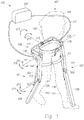
- Figure 1 is a perspective drawing illustrating a lower extremity exoskeleton 100 wearable by a person 187 that is able to decrease the wearer's energy consumption during walking.
- Lower extremity exoskeleton 100 in addition to other components, includes two leg supports 101 and 102, which are configured to be coupled to person's lower limbs 143 and 144 and configured to rest on the ground during the stance phase.
- the leg supports in addition to other components, include thigh links 103 and 104 and shank links 105 and 106.
- Two knee joints 107 and 108 are configured to allow flexion and extension between the shank link and the thigh link of the leg supports (shown by a knee flexion arrow 213 and a knee extension arrow 214 respectively) during the corresponding leg support swing phase. However, two knee joints 107 and 108 in some embodiments are configured to resist flexion between the shank link and the thigh link of the leg supports during the corresponding leg support stance phase.
- Lower extremity exoskeleton 100 further comprises an exoskeleton trunk 109.
- Exoskeleton trunk 109 comprises an upper body interface device 150. Exoskeleton trunk 109 is configurable to be coupled to the person's upper body 149 through upper body interface device 150.
- Person's upper body 149 means any location generally above the thighs including the buttock.
- Examples of upper body interface device 150 comprise an element or combination of elements including, without limitation, vests, belts, straps, shoulder straps, chest straps, body cast, harness, and waist belts.
- Exoskeleton trunk 109 is rotatably connectable to leg supports 101 and 102 at hip flexion-extension joints 125 and 126, allowing for the hip flexion and extension rotations (shown by hip extension arrow 215 and hip flexion arrow 216 respectively) of leg supports 101 and 102 about hip flexion-extension axes 151 and 152 respectively.
- Leg supports 101 and 102 are configurable to be coupled to the person's lower limbs 143 and 144 through lower limb interface straps 135 and 136.
- lower limb interface straps 135 and 136 are coupled to thigh links 103 and 104.
- lower limb interface straps 135 and 136 are coupled to shank links 105 and 106.
- lower limb interface straps are coupled to both shank links and thigh links.
- Each lower limb interface strap 135 and 136 comprises an element or combination of elements including, without limitation, straps, bars, c-shaped brackets, a body cast, and elastomers.
- lower extremity exoskeleton 100 couples to (i.e., wears) lower extremity exoskeleton 100 through upper body interface device 150 (a simple belt in the case of Figure 1 ) and by coupling two leg supports 101 and 102 through lower limb interface straps 135 and 136.
- Lower extremity exoskeleton 100 further comprises two hip actuators 145 and 146 which are configured to create torques between exoskeleton trunk 109 and leg supports 101 and 102.
- Right hip actuator 145 is shown in Figure 1
- left hip actuator 146 is shown in Figure 2 .
- Lower extremity exoskeleton 100 further comprises at least one power unit 201 capable of providing power and coupled to hip actuators 145 and 146.
- hip actuators 145 and 146 are powered by compressed gas.
- exoskeleton trunk 109 is configured to hold a rear load behind person 187. In some embodiments, exoskeleton trunk 109 is configured to hold a load in front of person 187.
- Figure 3 shows a configuration of lower extremity exoskeleton 100 where right leg support 101 and person's right lower limb 143 are in the swing phase and left leg support 102 and person's left lower limb 144 are in the stance phase (left leg support 102 is not shown in Figure 3 ).
- exoskeleton trunk 109 has been designed to extend along the person's back to hold a rear load 118. Further note that the following analysis clearly holds for the reverse configuration where left leg support 102 is in swing phase and right leg support 101 is in stance phase.
- power unit 201 is configured to cause the corresponding right hip actuator 145 of right leg support 101 to create a torque profile. Due to this torque profile, right leg support 101 and person's right lower limb 143 swing, as shown in Figure 3 .
- the mechanical work produced by right hip actuator 145 during the entire swing phase is denoted by.
- the total mechanical energy (kinetic energy plus potential energy) of right leg support 101 at the beginning of the swing phase is denoted by.
- the total mechanical energy of right leg support 101 at the end of the swing phase is denoted by E C .
- E LOSS The energy wasted to friction and other losses during the swing phase of right leg support 101 are denoted by E LOSS .
- W ACTUATOR is larger than ( E C - E A + E LOSS )
- energy is transferred from right hip actuator 145 to swing person's right lower limb 143, and its magnitude is [ W ACTUATOR - ( E C - E A + E LOSS )].
- W ACTUATOR i.e., mechanical energy produced by right hip actuator 145)
- E C - E A + E LOSS energy is transferred from person's right lower limb 143 to swing leg support 101, and its magnitude is [( E C - E A + E LOSS ) - W ACTUATOR ].
- the required energy to move exoskeleton right leg support 101 through the swing phase when right leg support 101 is not worn by person 187 is ( E C - E A + E LOSS ).
- An incremental mechanical energy transferred to person 187 during the swing phase will result in an incremental decrease in the wearer's energy required during the swing phase. Since the wearer's oxygen consumption is proportional to the energy expenditure, a decrease in the wearer's energy required for swinging a leg leads to less oxygen consumption for the wearer.
- right hip actuator 145 of right leg support 101 should create a torque profile such that mechanical energy is transferred to person 187 from swinging leg support 101. If the transferred mechanical energy is sufficiently large during that segment, the wearer's oxygen consumption is reduced while walking.
- One way to ensure that energy is transferred from right hip actuator 145 to move person's right lower limb 143 during the swing phase is to ensure that the torque profile of right hip actuator 145, during a portion of the swing phase, is larger than the torque required to move right leg support 101 through the same swinging trajectory when person 187 is not present. This is described below.
- Figure 4 shows a configuration of lower extremity exoskeleton 100 when right leg support 101 is in the swing phase (the same configuration as Figure 3 without the person drawn).
- Support surface or ground 130 has a slope of with the horizontal ground 134.
- Person's upper body 149 is coupled to exoskeleton trunk 109 by an upper body interface device 150, such as the one depicted in Figure 1 .
- an upper body interface device 150 such as the one depicted in Figure 1 .
- exoskeleton trunk 109 is not moving. This assumption is given here to simplify the equations and to better understand the conditions needed to decrease the wearer's energy expenditure. The results arrived at can be extended to the situation where exoskeleton trunk 109 travels forward.
- wearer's lower limb 143 and leg support 101 are coupled to each other by lower limb interface strap 135. In some embodiments of the invention, wearer's lower limb 143 and leg support 101 are coupled to each other through exoskeleton feet 139 and 140 as shown in Figure 18 .
- the type of coupling between wearer's lower limb 143 and leg support 101 dictates the locations of the interaction forces between wearer's lower limb 143 and leg support 101.
- Figure 4 shows the situation where two forces from wearer's lower limb 143 (not shown in Figure 4 ) are imposed on leg support 101. Force F T is imposed on thigh link 103 and force F S is imposed on shank link 105 by lower limb 143.
- T H The summation of all torques from wearer's lower limb 143 onto leg support 101 is denoted as T H .
- T H The summation of all torques from wearer's lower limb 143 onto leg support 101.
- T E The torque provided by right hip actuator 145 (depicted in Figure 1 ) between exoskeleton trunk 109 and right leg support 101 is denoted by T E .
- T E Positive values for T E indicate counterclockwise torque to swing leg support 101 along the forward swing direction 162 shown in Figures 3 and 4 .
- T E ⁇ T H M SHANK L THIGH 2 + I THIGH ⁇ ⁇ 1 + M SHANK L SCG L THIGH ⁇ ⁇ 2 2 Sin ⁇ 1 ⁇ ⁇ 2 + ⁇ ⁇ 2 Cos ⁇ 1 ⁇ ⁇ 2 + M THIGH L TCG gSin ⁇ 1 + M SHANK L THIGH gSin ⁇ 1 + T F where:
- Equation (3) represents the required torque to move right leg support 101 during swing phase through the same trajectory when right leg support 101 is not worn by the person's right lower limb 143.
- Case 1 the hip actuator torque, T E , is such that it is larger than the entire term on the right side of equation (3), then the torque from person's right lower limb 143 onto right leg support 101, T H , is positive.
- Case 1 teaches that to reduce the wearer's walking energy expenditure, during at least one portion of the swing phase of a leg support, the hip actuator of the swinging leg support should create a torque profile such that the torque from the swinging leg support onto the person's corresponding lower limb is in the direction of the person's swing velocity. If the torque from the swinging leg support onto the corresponding person's lower limb is sufficiently large, then the wearer's energy expenditure during the swing phase will be reduced. If the torque from the swinging leg support onto the corresponding person's lower limb is sufficiently large, then the wearer's oxygen consumption is reduced while walking.
- Case 1 also teaches that to reduce the wearer's walking energy expenditure during at least one portion of the swing phase of a leg support, the hip actuator of the swinging leg support should create a torque profile such that the force from the swinging leg support onto the person's corresponding lower limb is in the direction of the person's swing velocity.
- the wearer's lower limb needs to be pushed forward by the swinging leg support during at least a segment of the swing phase when the lower limb is moving forward. If the force from the swinging leg support onto the corresponding person's lower limb is sufficiently large, then the wearer's energy expenditure during the swing phase will be reduced. If the force from the swinging exoskeleton leg support onto said corresponding person's lower limb is sufficiently large, then the wearer's oxygen consumption is reduced while walking.
- the above Case 1 further teaches that to reduce the wearer's walking energy expenditure, during at least one portion of the swing phase of a leg support, the hip actuator of the swinging leg support should create a torque profile which is larger than the torque required to move the swinging leg support during that said portion of the swing phase through the same trajectory when not worn by the person. If the torque profile created by the actuator of the swinging leg support is sufficiently large, the wearer's energy expenditure during the swing phase will be reduced. If the torque profile created by the actuator of the swinging leg support is sufficiently large, the wearer's oxygen consumption is reduced while walking.
- any lower extremity exoskeleton decreases its wearer's energy expenditure during swing phase as long as the force from the exoskeleton leg support onto the wearer's lower limb during the swing phase is along the direction of the person's swing leg velocity.
- the force on the person's lower limb during the swing phase is along the direction of the person's swing leg velocity
- mechanical power is transferred from the exoskeleton to the person.
- Mechanical energy transferred to the person during a portion of the swing phase will result in an incremental decrease in the wearer's energy required for locomotion during the swing phase.
- An incremental decrease in the wearer's energy required for locomotion leads to less oxygen consumption and lower heart rate while walking.
- lower extremity exoskeleton 100 comprises at least one signal processor 159 capable of controlling hip actuators 145 and 146, as depicted in Figure 9 .
- Signal processor 159 comprises an element or combination of elements selected from a group including analog devices, analog computation modules, digital devices including, without limitation, small-, medium-, and large-scale integrated circuits, application specific integrated circuits, programmable gate arrays, and programmable logic arrays, electromechanical relays, solid state switches, MOSFET switches, and digital computation modules including, without limitation, microcomputers, microprocessors, microcontrollers, and programmable logic controllers.
- signal processor 159 In operation, to decrease the wearer's energy expenditure, signal processor 159, among other tasks, computes a torque profile that satisfies the condition described in Case 1 above. This torque is then produced by hip actuators 145 and 146 during their respective swing phases. There are many ways of implementing the condition described in Case 1, and some methods are described below.
- signal processor 159 computes a torque profile as described in Case 1 above for hip actuators 145 and 146.
- the hip actuator torque can be controlled to satisfy the condition described in Case 1 by creating a closed loop control by measuring the hip actuator torque or force as the feedback variable. A skilled control engineer will be able to develop a controller to satisfy the condition described in Case 1 above.
- Figure 4 shows that in order to reduce the wearer's energy expenditure during the swing phase, the force on wearer's lower limb 143 should be in the direction of the swing velocity during a portion of the swing phase.
- the wearer's lower limb should be pushed in the direction of motion by the exoskeleton's lower limb during a portion of the swing phase.
- This can be done either in a closed loop fashion or in an open loop fashion. In the closed loop fashion, one can develop a control algorithm to ensure a force is imposed on wearer's lower limb 143 that creates a torque along the swing velocity. In other words, the wearer's lower limb 143 is pushed forward during a portion of the swing phase.
- this can be done by adding a force sensor between wearer's lower limb 143 and right leg support 101 and creating a closed loop force controller.
- the closed loop controller measures the force between wearer's lower limb 143 and right leg support 101 and creates a torque for hip actuator 145 to ensure that this force on wearer's lower limb 143 is pushing wearer's lower limb 143 in the direction of motion.
- Figure 5 shows a general embodiment of the control block diagram where the force on wearer's lower limb 143 is measured and compared with a desired force onto wearer's lower limb 143 in the direction of the swing velocity.
- the controller is used to ensure that the force on wearer's lower limb 143 follows the desired force which is along forward swing direction 162. This means that to reduce the wearer's energy expenditure, the controller ensures wearer's lower limb 143 is pushed in the direction of motion during a portion of the swing phase.
- the desired force on wearer's lower limb should be chosen to be comfortable for the user.
- f is a function that guarantees that the torque profile from hip actuator, T E , during a portion of the swing phase is larger than the required torque to move the leg support in swing phase through the same trajectory when not worn by the person's lower limb.
- f is a constant quantity.
- f is a constant and positive quantity. In some embodiments, f is a function of time. The choice of T E , as shown by equation (4), ensures that the person's lower limb is pushed along the direction of swing during a portion of the swing phase.
- g is a constant quantity and larger than the right hand side of equality (3) during a portion of the swing phase.
- g is a function of time and larger than the right hand side of equality (3) during a portion of the swing phase.
- g is a function of the percentage of the swing phase duration and larger than the right hand side of equality (3).
- the torque T E may be constant for a set percentage of the swing phase, and then reduced to zero during the remainder of the swing phase. In some embodiments, torque T E could start at a maximum at the beginning of the swing phase and decay as a linear function of time, reaching zero later in the swing phase. In all of the above cases, as long as the mechanical work produced by the hip actuator during the swing phase is larger than the energy needed to swing the exoskeleton leg support, then energy is transferred from the hip actuator to move the person's lower limb. Because the exact length of a swing cycle cannot be known until the swing leg contacts the ground, one might estimate the length of the current swing cycle based on the length of previous swing cycle(s) of that leg and/or the other leg. Therefore, T E , in some embodiments, can be formed based on the previous step (or steps) as any arbitrary function as long as energy is transferred to the wearer as described in Case 1 above.
- the time to start applying torque in the swing direction is very important.
- power unit 201 must be configured to cause right hip actuator 145 of right leg support 101 to begin imposing a torque on leg support 101 in forward swing direction 162 when leg support 102 strikes the ground.
- the power unit 201 must be configured to cause left hip actuator 146 of left leg support 102 to begin imposing a torque on leg support 102 in forward swing direction 162 when leg support 101 strikes the ground.
- the torque imposed on any of these leg supports during the double stance will continue through at least a portion of their swing phase to ensure energy transfer to the wearer's corresponding lower limb.
- the torque on leg support 101 is chosen based on a set of information collected during at least one previous step. This could include, for example, an estimate of the current walking speed.
- the torque on leg support 101 is chosen such that the force from leg support 101 onto the corresponding person's lower limb 143 is in the direction of the person's lower limb forward swing 162. In some embodiments, the torque is calculated to maximize the force from leg support 101 onto the corresponding person's lower limb 143 without the person becoming uncomfortable. In some embodiments, the force from leg support 101 onto the corresponding person's lower limb 143 is sufficiently large such that the wearer's oxygen consumption is reduced while walking. In some embodiments, torque on leg support 101 rises to a nominal value and stays substantially constant during toe-off of leg support 101.
- Torque on leg support 101 rises to a nominal value and varies no more than fifty percent from its nominal value during double stance and through toe-off of leg support 101. In some embodiments, torque on leg support 101 is substantially unidirectional. Torque on leg support 101 rises to a nominal value and stays within fifty percent of its nominal value during double stance, toe-off, and the majority of the period from toe-off to heel strike of said first leg support.
- FIGS 27a-27f Some examples of advantageous hip torque profiles are shown in Figures 27a-27f .
- the plot of Figure 27a shows a torque profile g where the torque on a leg support rises to a constant value immediately upon the heel strike of the opposite leg support, and then stays constant throughout toe-off and the majority of swing until finally changing to a value near zero at the end of the swing phase in order to allow the user to decelerate the swinging leg at the end of swing phase.
- the torque at the end of swing phase is zero, which is shown in Figure 27b .
- the plot of Figure 27b also shows that the torque may ramp down to zero in a variety of ways such as the linear slope shown.
- FIG. 27c Another example which we have also demonstrated is shown in Figure 27c .
- the plot of Figure 27c shows a torque profile g that starts out relatively constant at the heel strike of the opposite leg support and then smoothly increases through toe-off and into the swing phase until it turns off in late swing phase.
- Figure 27d Another example is shown in Figure 27d .
- torque profile g rises quickly to a constant value at the heel strike of the opposite leg support, remains constant until the toe-off, and then transitions to a torque proportional to and in the same direction as the current hip angular velocity.
- the initial constant torque and the proportionality constant are selected in order to insure that there is a relatively smooth transition between the constant torque value and the torque calculated using the proportionality to the hip angular velocity.
- the torque after toe-off is calculated by summing a term proportional to the current angular velocity of the hip joint with a value which is proportional to the sine of the angle of the thigh link with respect to gravity.
- the magnitude of the torque and the duration of the torque profile must be controlled to insure two things: 1) that the torque is large but not uncomfortable and 2) that the torque reduces at the proper time in late swing.
- the magnitude of the initial constant torque shown in all the plots of Figures 27a-27f is set by a combination of factors which might include a user setting and the current walking speed of the user (taken from previous steps).
- the user setting is used to set the general level of assistance in swing at all walking speeds, and it is set according to the user's preference.
- the current walking speed is used to scale the magnitude of the torque so that the user gets more assistance at high walking speeds and less at low speeds.
- the proper duration of the torque profile (the time at which it reduces in late swing) may be determined from the current walking speed, it may be determined by the swing angle, or it may be determined from other system variables.
- signal processor 159 increases the actuator torque or force.
- signal processor 159 becomes aware that person 187 has begun to walk faster when the torque from the exoskeleton leg support onto the person's lower limb during swing is not sufficiently larger along forward swing direction 162 or is in the opposite direction to the forward swing direction 162.
- measuring the force between the exoskeleton leg support and the person's lower limb reveals that the person has increased its walking speed.
- the force from the exoskeleton leg support onto the person's lower limb during swing is not sufficiently large along forward swing direction 162 or is in the opposite direction to the forward swing direction 162, it is evidence that person 187 has increased its walking speed.
- Signal processor 159 in some embodiments, is mounted to exoskeleton trunk 109. In some embodiments, signal processor 159 is located inside power unit 201. Signal processor 159 may be a simple mechanical device consisting of a hydraulic or pneumatic circuit or it may include electronic elements as well.
- hip actuators 145 and 146 each comprise of a hydraulic hip actuator.
- at least one power unit 201 provides hydraulic power to hip actuators 145 and 146.
- only one power unit 201 provides hydraulic power to hydraulic hip actuators 145 and 146.
- each hydraulic hip actuator receives hydraulic power from separate power units.
- power unit 201 as shown in Figure 6 , among other components, comprises at least one hydraulic circuit 194 connectable to at least one of hydraulic hip actuators 145 and 146, and modulates the hydraulic fluid flow to and from hydraulic hip actuators 145 and 146.
- hydraulic hip actuators 145 and 146 are hydraulic piston-cylinders.
- hydraulic hip actuators 145 and 146 are rotary hydraulic vane type hydraulic actuators.
- hydraulic circuit 194 among other components, comprises a hydraulic pump 240 coupled to an electric motor 241.
- a torque profile can be implemented on hip actuators 145 and 146 to satisfy the condition described in Case 1 above. Since the torque is a function of the hydraulic pressure and the hip actuator geometry, the hip actuator torque can be controlled by creating a closed loop control on the electric motor 241 by measuring the hydraulic pressure as the feedback variable. In some embodiments, the hip actuator torque can be controlled to satisfy the condition described in Case 1 above by creating a closed loop control on the electric motor 241 by measuring the hip actuator torque or force as the feedback variable.
- hydraulic circuit 194 further comprises an actuated flow-restricting valve 200 capable of redirecting hydraulic fluid from hydraulic right hip actuator 145 around hydraulic pump 240.
- actuated flow-restricting valve 200 In operation, when hydraulic pump 240 is in use, actuated flow-restricting valve 200 is closed. In operation, when it is necessary to reduce the power consumption, electric motor 241 will not be powered. In that case, actuated flow restricting valve 200 may be opened so that unpowered electric motor 241 and pump 240 will not impede the motion of right hip actuator 145.
- hydraulic circuit 194 further comprises a three-way valve 242.
- three-way valve 242 connects hydraulic right hip actuator 145 to hydraulic pump 240.
- three-way valve 242 may redirect hydraulic fluid from hydraulic right hip actuator 145 around hydraulic pump 240 so that unpowered electric motor 241 and pump 240 will not impede the motion of right hip actuator 145.
- a hydraulic circuit usually has many other components associated with safety and other features not discussed here.
- Figures 6 , 7 and 8 show only those components that are needed to accomplish the described tasks.
- Hydraulic hip actuators 145 and 146 comprise of any hydraulic actuators or combination of actuators capable of converting pressurized hydraulic fluid into force or torque.
- hydraulic actuators include, without limitation, linear hydraulic piston-cylinders, rotary hydraulic actuators, rack-and-pinion-type rotary actuators, and rotary hydraulic vane type actuators where pressurized hydraulic fluid generates force or torque by pushing against moving surfaces.
- Actuated flow restricting valve 200 comprises any valve or combination of valves capable of performing the indicated functions.
- Examples of actuated flow restricting valve 200 include, without limitation, flow control valve, pressure control valve, actuated needle valves, solenoid valves, and on-off valves.
- Hydraulic pump 240 comprises any pump or combination of pumps capable of performing the indicated functions.
- Examples of hydraulic pump 240 include, without limitation gear pump, vane pump, axial piston pump, and radial piston pump.
- Electric motor 241 comprises any device or combination of devices capable of driving hydraulic pump 240.
- Examples of motor 241 include, without limitation, electric motors, including, without limitation, AC (alternating current) motors, brush-type DC (direct current) motors, brushless DC motors, electronically commutated motors (ECMs), stepping motors, and combinations thereof.
- AC alternating current
- brush-type DC direct current
- brushless DC brushless DC
- ECMs electronically commutated motors
- stepping motors and combinations thereof.
- signal processor 159 computes a torque profile as described in Case 1 above for hip actuators 145 and 146 by controlling electric motor 241. Since the torque is a function of the hydraulic pressure and the hip actuator geometry, the hip actuator torque, in some embodiments as shown in Figure 8 , can be controlled by creating a closed loop control on the electric motor 241 by measuring the hydraulic pressure as the feedback variable. A pressure sensor indicated at 236 measures the pressure of the hydraulic fluid and signal processor 159 ensures that the pressure is regulated to the desired value. The closed loop control of the hip actuator torque allows one to generate arbitrary known torque profiles for the hip actuator during the swing phase to ensure energy is transferred to the wearer.
- the generated torque is a function of the system states during the previous step (or steps) and ensures the condition of Case 1 above is satisfied.
- the hip actuator torque can be controlled to satisfy the condition described in Case 1 above by creating a closed loop control on the electric motor 241 by measuring the hip actuator torque or force as the feedback variable. A skilled control engineer will be able to develop a controller to satisfy the condition described in Case 1 above.
- lower extremity exoskeleton 100 comprises at least one stance sensor per leg support which produces a stance signal indicating whether that leg support is in the stance phase.
- leg support 101 includes stance sensor 160, which produces a stance signal 219. Stance signal 219 indicates whether leg support 101 is in the stance phase.
- leg support 102 includes stance sensor 161, which produces a stance signal 220. Stance signal 220 indicates whether leg support 102 is in the stance phase.
- stance sensors 160 and 161 are coupled to shank links leg support 101 and 102 respectively.
- signal processor 159 computes a torque profile to satisfy the condition described in Case 1 above depending on whether stance signals 219 and 220 indicate if leg supports 101 and 102 are either in the stance phase or in the swing phase.
- stance sensors 160 and 161 are located inside the human shoe (or boots) soles. In some embodiments, stance sensors 160 and 161 are connectable to the bottom of human shoes or boots.
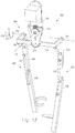
- exoskeleton trunk 109 in addition to other components, comprises two hip links 114 and 115 rotatably connectable to thigh links 103 and 104 at hip flexion-extension joints 125 and 126, allowing for the flexion and extension of leg supports 101 and 102 about hip flexion-extension axes 151 and 152 respectively.
- hip links 114 and 115 are rotatably connected to each other at hip abduction-adduction joint 113, allowing for abduction and/or adduction of leg supports 101 and 102.
- Abduction and adduction of leg supports 101 and 102 are shown by arrows 217 and 218 respectively.
- Figure 10 shows another embodiment of the invention where exoskeleton trunk 109 further comprises a hip resilient element 116 configured to apply a torque between hip links 114 and 115.
- a hip resilient element include, without limitation, extension spring, compression spring, leaf spring, gas spring, air spring, rubber, elastomer, surgical tube, bungee cord, and combinations thereof.
- the stiffness of hip resilient element 116 may be chosen such that its force generally holds up the weight of the leg supports 101 or 102 during swing phase.
- exoskeleton trunk 109 is configured to hold a rear load 118 behind person 187.
- Figure 11 is a perspective drawing wherein exoskeleton trunk 109, among other components, further comprises a connecting bracket 117 configured to transfer the weight of a rear load 118 to exoskeleton trunk 109.
- connecting bracket 117 further comprises extension frames 119 and 120 configured to hold front load 154 in front of person 187.
- Examples of rear load 118 and front load 154 include without limitation, backpack, baby carrier, food containers, sacks, boxes, water jugs, tool boxes, barrels, ammunition, weaponry, bedding, first aid supplies, golf bags, mail bags, camera, steadycam, leaf blower, compressor, electromechanical machineries, and combinations thereof.
- rear load 118 and/or front load 154 is another person being carried by person 187.
- exoskeleton trunk 109 supports a portion of the weight of person 187 through human upper body interface device 150.
- hip abduction stop 211 may also include a hip abduction stop 211 which limits or prevents hip links 114 and 115 from abducting with respect to each other.
- hip abduction stop 211 is created using a wire rope. Wire rope hip abduction stop 211 prevents abduction of leg supports 101 and 102 past some angle from occurring but allows adduction of leg supports 101 and 102.
- Figure 14 is a perspective drawing where exoskeleton trunk 109 includes two hip links 114 and 115 rotatably connectable to thigh links 103 and 104 allowing for flexion and extension of leg supports 101 and 102 relative to exoskeleton trunk 109, wherein hip links 114 and 115 are compliantly connected to each other, allowing for abduction and/or adduction of leg supports 101 and 102. In the example shown in Figure 14 , this is accomplished by a leaf spring acting as hip resilient element 153.
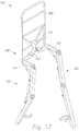
- Figure 15 is a perspective drawing wherein exoskeleton trunk 109, among other components, further comprises a connecting bracket 117 configured to transfer the weight of a rear load 118 to exoskeleton trunk 109.
- Exoskeleton trunk 109 further comprises two hip links 114 and 115 rotatably connectable to thigh links 103 and 104 allowing for flexion and extension of leg supports 101 and 102 relative to exoskeleton trunk 109.
- Hip links 114 and 115 are rotatably connected to connecting bracket 117 via two hip abduction-adduction joints 176 and 177 and rotate about two hip abduction-adduction axes 178 and 179.
- hip abduction-adduction axes 178 and 179 are generally parallel to each other. In some embodiments, hip abduction-adduction joints 176 and 177 coincide with each other. Furthermore, in some embodiments, as shown in Figures 9-12 , hip abduction-adduction joints 176 and 177 coincide with each other forming hip abduction-adduction joint 113, and hip abduction-adduction axes 178 and 179 become one hip abduction-adduction axis 112.
- exoskeleton trunk 109 further comprises abduction-adduction hip resilient elements 121 and 122 configured to apply torques between hip links 114 and 115 and connecting bracket 117.
- hip abduction-adduction resilient elements include, without limitation, extension spring, compression spring, gas spring, air spring, rubber, surgical tube, leaf springs, bungee cord, and combinations thereof.
- the stiffness of abduction-adduction hip resilient elements 121 and 122 may be chosen such that its force generally holds up the weight of the leg supports 101 or 102 during swing phase and aid the person in keeping the load oriented vertically while walking.
- hip links 114 and 115 are compliantly connected to connecting bracket 117. In the embodiment shown in Figure 17 , this is accomplished by a hip resilient element 153 which, in this case, is a leaf spring.
- exoskeleton trunk 109 comprises a backpack frame 180 that allows a backpack to be coupled to lower extremity exoskeleton 100.
- backpack frame 180 is connected to connecting bracket 117.
- the upper body interface devices 150 (such as a belt and shoulder straps) have been omitted in this figure for clarity; however, upper body interface devices 150, in some embodiments, can be coupled to backpack frame 180 or connecting bracket 117.
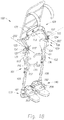
- leg supports 101 and 102 further include thigh abduction-adduction joints 123 and 124 which are configured to allow abduction and/or adduction of leg supports 101 and 102 about thigh abduction-adduction axes 202 and 203 respectively.
- thigh abduction-adduction joints 123 and 124 are located below hip flexion-extension joints 125 and 126. These joints are shown in greater detail in Figure 19 which is a partial view of the same embodiment of Figure 18 .
- right leg support 101 includes a thigh adduction stop 185 which limits or prevents right thigh link 103 from adducting at thigh abduction-adduction joints 123 and 124. Abduction and adduction of right leg support 101 are shown by arrows 227 and 228 respectively.
- right thigh abduction-adduction joint 123 includes a thigh adduction stop 185 which bears on a thigh stop surface 186.
- Thigh adduction stop 185 limits the adduction of thigh abduction-adduction joint 123.
- leg supports 101 and 102 further include leg rotation joints 127 and 128 configured to allow rotation of leg supports 101 and 102.
- Leg rotation joints 127 and 128 are generally located above knee joints 107 and 108.
- Lines 164 and 165 represent the leg rotation axes of leg rotation joints 127 and 128. In Figures 19 and 20 , this is accomplished by providing a sliding contact between the right hip rotation shaft 166 and the right hip rotation journal 168.
- the parts included in the joint which prevent it from pulling apart have been omitted for simplicity, but one skilled in the art will note that there are many ways of retaining such shafts in such journals.
- leg rotation joints 127 and 128 further comprise of a rotation resilient element 129.
- This rotation resilient element acts as a torsion spring and provides a restoring torque which generally restores the leg support back to the neutral position shown in Figure 18 .
- Rotation resilient element 129 can be constructed in many ways with the particular cross section shown in Figure 20 being advantageous when using an elastomeric material to construct the element. Rotation resilient element 129 is shown partially deflected for illustration purposes.
- leg supports 101 and 102 further comprise of compression-elongation mechanisms 131 and 132 configured to change the distance between exoskeleton trunk 109 and the respective knee flexion-extension joints 107 and 108.
- compression-elongation mechanisms 131 and 132 allow for changes in the distance between the hip flexion-extension joints 125 and 126 and the respective flexion-extension knee joints 107 and 108.
- the compression-elongation mechanisms contracts by right hip rotation shaft 166 sliding further into the right hip rotation journal 168 (shown for right leg 101 only).
- the leg rotation resilient element 129 is allowed to slide into a clearance cavity 170.
- compression-elongation mechanisms 131 and 132 further comprise of a right leg compression-elongation resilient element 133.
- This leg compression-elongation resilient element acts as a spring and provides a restoring force which generally restores the leg support back to a neutral configuration. In the embodiment of Figure 20 , this is illustrated by a helical compression spring.
- exoskeleton hip mechanism cover 171 may cover some components of exoskeleton including parts of hip links 114 and 115, hip resilient element, or abduction-adduction hip resilient elements 121 and 122.
- leg supports 101 and 102 further comprise of exoskeleton feet 139 and 140 coupled to shank links 105 and 106 respectively, allowing the transfer of forces from shank links 105 and 106 to the ground.
- exoskeleton feet 139 and 140 are configurable to be coupled to the feet of person 187.
- the coupling to the person's feet is accomplished by using clam-shell type bindings 205 and 206 sometimes found on modern snow shoes.
- clam-shell type bindings 205 and 206 sometimes found on modern snow shoes.
- there are a great number of methods to make such a connection as can be seen on different types of snow skis, snowboards, snowshoes, and other such devices.
- exoskeleton feet 139 and 140 comprise of exoskeleton shoes 188 and 189 wearable by person 187, thereby allowing exoskeleton feet 139 and 140 to couple to the feet of person 187.
- exoskeleton feet 139 and 140 comprise of exoskeleton insoles 157 and 158 insertable inside the person's shoes, allowing exoskeleton feet 139 and 140 to couple to the feet of person 187.
- Insoles 157 and 158 are flexible and therefore, can bend to match the curvature of the human foot during maneuvers such as squatting.
- the insole side supports 212 are either compliant or configured to include degrees of freedom to mimic the movement of the human ankle.
- exoskeleton feet 139 and 140 are compliantly coupled to shank links 105 and 106. This is accomplished using ankle resilient elements 181 and 182.
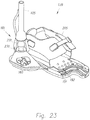
- Figure 23 shows a close-up view of right exoskeleton foot 139.
- right ankle resilient element 181 is constructed of a metal ball-and-socket joint 231 surrounded by a doughnut shaped elastomer element 230 which creates compliance in all directions of rotations.
- exoskeleton feet 139 and 140 rotate about two plantar-dorsi flexion axes relative to shank links 105 and 106.
- Figure 24 shows an embodiment of this type of exoskeleton where right ankle plantar-dorsi flexion axis 172 is generally parallel to the plantar-dorsi flexion axis in the human ankle.
- each leg support further comprises at least one ankle plantar-dorsi flexion resilient element 141 resisting the rotation of respective exoskeleton foot about right ankle plantar-dorsi flexion axis 172.
- exoskeleton feet 139 and 140 rotate about two ankle abduction-adduction axes relative to shank links 105 and 106.
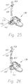
- Figure 25 shows an embodiment of this type of exoskeleton where right ankle abduction-adduction axis 174 is generally parallel to the abduction-adduction axis in the human ankle.
- each leg support further comprises at least one ankle abduction-adduction resilient element 142 resisting the rotation of right exoskeleton foot 139 about right ankle abduction-adduction axis 174.
- exoskeleton feet 139 and 140 rotate about two ankle rotation axes 147 and 148 relative to shank links 105 and 106. In some embodiments, as shown in Figure 26 , this is accomplished using a shank rotation joint 207 which functions similar to leg rotation joint 127.
- Figure 26 shows an embodiment of this type of exoskeleton where right ankle rotation axis 147 is generally parallel to the rotation axis in the human ankle.
- resilient elements can be included in the ankle to resist the rotation of right exoskeleton foot 139 about right ankle rotation axis 147.
- Figures 27a-27f depict torque during the use of the exoskeleton of the present invention as depicted in Figure 5 and utilizing exoskeleton foot 139.
- the analysis above describing power transfer between person 187 and lower extremity exoskeleton 100 applies to Figures 27a-27f , if one assumes the rotation of right leg support 101 about at a right ankle point.
- stance sensors 160 and 161 are integrated into exoskeleton feet 139 and 140.
- stance sensor 160 is a pressure sensor measuring the pressure in a media 191 trapped in a stance sensor cavity 192 inside right exoskeleton foot 139.
- Figure 23 shows an embodiment where a tube is used as a stance sensor cavity 192.
- the stance signals 219 and 220 may take the form of the media 191 itself, ported in a small tube from stance sensor cavity 192 to signal processor 159.
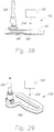
- Figure 29 shows another embodiment wherein stance sensor 160 is a force sensor connectable to right exoskeleton foot 139.
- stance sensor 160 is located inside the human shoe like an insole and its output signal represents the force on the bottom of the human foot. This type would be particularly useful in embodiments of the invention such as those shown in Figures 21 or 22 .
- stance sensor 160 is connected to the bottom of the human shoe and senses the force on the bottom of the human foot.
- stance sensor 160 is located inside the human shoe sole and senses the force on the bottom of the human foot.
- stance sensors 160 and 161 are coupled to shank links 105 and 106 respectively.
- Stance sensor 160 comprises any sensor or combination of sensors capable of performing the indicated functions.
- Examples of stance sensor 160 include, without limitation, force sensors, strain-gage based force sensors, piezoelectric force sensors, force sensing resistors, pressure sensors, switches, tape switches, and combinations thereof.
- stance sensor 160 is a switch that represents the existence of a force greater than some threshold force on the bottom of the foot of person 187.
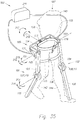
- FIG. 33 shown in Figure 33 is an additional thigh abduction-adduction joint 235 which is included in order to allow the leg to be stowed in a vertical position when the exoskeleton is not in use but needs to be carried.
- Right leg support 101 can abduct along an additional right thigh abduction-adduction axis 237. This may be desirable if person 187 no longer has a very heavy load to carry but needs to transport lower extremity exoskeleton 100. In that case, the operator may unstrap the exoskeleton's right leg support 101 and swing the leg outward from his or her body until the right exoskeleton foot 139 is in the air over the operator's head.
- the leg can be positioned such that it stows behind the operator as shown in Figure 33 .
- the right thigh abduction-adduction joint 123 and the additional right thigh abduction-adduction joint 235 each allow for a rotation of approximately ninety degrees about the right thigh abduction-adduction axis 202 and the additional right thigh abduction-adduction axis 237 respectively. Therefore, the total abduction possible is over 180 degrees.
- lower extremity exoskeleton 100 (as shown in Figure 1 ) comprises two torque generators 110 and 111 which are configured to allow flexion of knee joints 107 and 108 during swing phase and resist flexion of knee joints 107 and 108 during stance phase, thereby allowing the lower extremity exoskeleton 100 to bear a load and transfer the load forces (e.g., load weight) to the ground.
- load forces e.g., load weight
- torque generators 110 and 111 are hydraulic torque generators.
- torque generators 110 and 111 are hydraulic piston cylinders where the motion of the piston relative to the cylinder creates hydraulic fluid flow into or out of the cylinder.
- the hydraulic fluid flow into or out of the cylinder may be controlled by a hydraulic valve.
- impedance of hydraulic torque generators 110 and 111 is defined as the ratio of the required force over the velocity in frequency domain. With this definition, the smaller the hydraulic valve orifice size is, the larger the impedance of the hydraulic torque generator will be.
- torque generators 110 and 111 are hydraulic rotary dampers where the torque produced may be controlled by a hydraulic valve.
- impedance of hydraulic rotary generators 110 and 111 is defined as the ratio of the required torque over the angular velocity in frequency domain. With this definition, the smaller the hydraulic valve orifice size is, the larger the impedance of the hydraulic rotary damper will be.
- torque generators 110 and 111 are friction brakes where one can control the resistive torque on knee joints 107 and 108 by controlling the friction torques.
- torque generators 110 and 111 are viscosity based friction brakes where one can control the resistive torque on knee joints 107 and 108 by controlling the viscosity of the fluid.
- torque generators 110 and 111 are Magnetorheological Fluid Devices where one can control the resistive torque on knee joints 107 and 108 by controlling the viscosity of the Magnetorheological Fluid.
- any of the above devices can be mounted in the invention to function in the same way as the hydraulic rotary dampers shown in Figure 35 .
- signal processor 159 is configured to control torque generators 110 and 111.
- Signal processor 159 controls the resistance to flexion in knee joints 107 and 108 as a function of stance signals 219 and 220 depicted in Figure 9 .
- signal processor 159 will increase the impedance of right torque generator 110 so that right knee joint 107 resists flexion.
- signal processor 159 will decrease the impedance of right torque generator 110 so that no resistance to flexion occurs in right knee joint 107.
- signal processor 159 when stance sensor 161 detects the stance phase in left leg support 102, signal processor 159 will increase the impedance of left torque generator 111 so that left knee joint 108 resists flexion. Conversely, when left stance sensor 161 detects the swing phase in left leg support 102, signal processor 159 will decrease the impedance of left torque generator 111 so that no resistance to flexion occurs in left knee joint 108. Large impedances of torque generators 110 and 111 lead to large resistance of knee joints 107 and 108 to flexion needed during the stance phase. Conversely, small impedances of torque generators 110 and 111 lead to small resistance of knee joints 107 and 108 to flexion needed during swing phase. In some embodiments, signal processor 159 is mounted to torque generators 110 and 111.
- the resistance to flexion in knee joints 107 and 108 during the stance phase need not be constant.
- the resistance to flexion at the beginning of the stance phase may be extremely high (i.e., knee joints 107 and 108 will be locked in the beginning of stance).
- the resistance to flexion may be lower, but high enough that knee joints 107 and 108 will only undergo a few degrees of flexion.
- the resistance to flexion may be low, but still nonzero, so that knee joints 107 and 108 may flex in preparation for the swing cycle.
- each of leg supports 101 and 102 further comprises a torque generator wherein each torque generator comprises a hydraulic piston-cylinder.
- power unit 201 comprises at least one knee hydraulic circuit 190 connectable to torque generators 110 and 111. See Figures 36-40 .
- Knee hydraulic circuit 190 is configured to modulate the fluid flow to torque generators 110 and 111. In operation (using right leg support 101 as an example), when right leg support 101 is in a stance phase, knee hydraulic circuit 190 is configured to restrict the fluid flow to right torque generator 110 of right leg support 101. When leg support 101 is in a swing phase, knee hydraulic circuit 190 is configured to allow the fluid flow to right torque generator 110 of right leg support 101.
- knee hydraulic circuit 190 when leg support 101 is in a stance phase, is configured to increase the resistance to flexion of right knee joint 107. Knee hydraulic circuit 190, when leg support 101 is in a swing phase, is configured to decrease the resistance to flexion of right knee joint 107.
- lower extremity exoskeleton 100 further comprises at least one stance sensor 160 and 161 per leg supports 101 and 102. Stance sensors 160 and 161 produce stance signals 219 and 220, indicating whether leg supports 101 and 102 are in the stance phase.
- knee hydraulic circuit 190 and hydraulic circuit 194 may be coupled to each other or share components. In some embodiments, one knee hydraulic circuit 190 may be used for both torque generator 110 and 111, or each of torque generators 110 and 111 may connect to an independent knee hydraulic circuit 190.
- Figure 36 shows an embodiment of the invention where knee hydraulic circuit 190 comprises a knee actuated flow-restricting valve 208 connecting right torque generator 110 to a hydraulic reservoir 195.
- knee actuated flow-restricting valve 208 restricts the fluid flow during stance phase and allows for minimum resistance fluid flow during the swing phase.
- one reservoir i.e., reservoir 195
- reservoir 195 is used to hold hydraulic fluid for both hydraulic circuit 194 and knee hydraulic circuit 190
- Figure 37 shows an embodiment of the invention where knee hydraulic circuit 190 comprises a hydraulic three-way valve 198 connecting right torque generator 110 to a hydraulic reservoir 195, either through a non-actuated flow restricting valve 196 or a bypass line 197.
- Hydraulic three-way valve 198 connects right torque generator 110 to hydraulic reservoir 195 through non-actuated flow restricting valve 196 during stance phase, thereby restricting the hydraulic flow and increasing the impedance of right torque generator 110.
- hydraulic three-way valve 198 connects right torque generator 110 to hydraulic reservoir 195 through bypass line 197, thereby increasing the hydraulic fluid flow and decreasing the impedance of right torque generator 110.
- Figure 38 represents another embodiment of knee hydraulic circuit 190 where a knee actuated flow-restricting valve 208 capable of controlling its orifice size and a check valve 199 connect torque generator 110 to hydraulic reservoir 195.
- signal processor 159 restricts the fluid flow by controlling the orifice of knee actuated flow-restricting valve 208.
- signal processor 159 opens knee actuated flow-restricting valve 208 and allows for fluid flow to torque generator 110, thereby decreasing the impedance of torque generator 110.
- Knee actuated flow-restricting valve 208 comprises any valve or combination of valves capable of performing the indicated functions. Examples of knee actuated flow-restricting valve 208 include, without limitation, flow control valves, pressure control valves, and on-off valves.
- Check valve 199 allows right knee joint 107 to extend easily (no or minimum resistance) at all times.
- Figure 39 represents another embodiment of knee hydraulic circuit 190. This embodiment is similar to the embodiment of Figure 37 but an additional check valve 199 has been added to allow right knee joint 107 to extend easily (no or minimum resistance) at all times.
- Figure 40 represents another embodiment of knee hydraulic circuit 190 where a two-way valve 193 capable of selecting between a set orifice size or fully open orifice, and check valve 199 connect torque generator 110 to hydraulic reservoir 195.
- signal processor 159 directs the fluid flow to torque generator 110 through the set orifice size of two-way valve 193.
- signal processor 159 directs the fluid flow to torque generator 110 through the fully open orifice of two-way valve 193.
- Check valve 199 allows right knee joint 107 to extend easily (no or minimum resistance) at all times.
- leg supports 101 and 102 are configured to allow flexion of the respective knee joints 107 and 108 during the swing phase and to resist flexion of the respective knee joints 107 and 108 during the stance phase by locking the knees.
- Figure 41 shows right leg support 101 in two configurations.
- right shank link 105 includes a shank stop 209 which bears on thigh stop 210 when the knee is hyperextended.
- the angle of right knee joint 107 at hyper-extension is illustrated as A in Figure 41 .
- knee joint 107 or 108 will go "over-center" when approaching hyper-extension, meaning that the knee will tend to lock against the stops if leg supports 101 or 102 is subject to a compressive load, as would be the case for right leg support 101 in the situation illustrated in Figure 41 .
- over-center mechanisms which generally tend to force the load vector on the leg support to pass in front of the knee joint.
- lower extremity exoskeleton 100 further comprises knee resilient elements 232 which are configured to encourage flexion of knee joints 107 and 108. This decreases the person's effort needed to flex knee joints 107 and 108 during the swing phase.
- knee resilient elements 232 are in parallel with torque generators 110 and 111.
- knee resilient elements 232 as shown in Figure 43 , are in series with torque generators 110 and 111.
- lower extremity exoskeleton 100 comprises knee resilient elements 232 which are configured to encourage extension of knee joints 107 and 108.
- knee resilient elements 232 can also be used with the embodiment of the exoskeleton shown in Figure 41 .
- the exoskeleton legs do not have to reach all the way to the ground to decrease the wearer's oxygen consumption.
- Any leg support including shank links only as shown in Figure 44 , decrease its wearer's energy expenditure, as long as the force from exoskeleton trunk onto the wearer's upper body is along the person's forward velocity.
- the mechanical energy transferred to the person during the stance phase will result in an incremental decrease in wearer's energy required for locomotion during the stance phase.
- An incremental decrease in the wearer's energy required for locomotion leads to less oxygen consumption and a lower heart rate.
- the various examples are, therefore, to be considered in all respects as illustrative and not restrictive.
Landscapes
- Health & Medical Sciences (AREA)
- Animal Behavior & Ethology (AREA)
- Public Health (AREA)
- Physical Education & Sports Medicine (AREA)
- Rehabilitation Therapy (AREA)
- Life Sciences & Earth Sciences (AREA)
- Epidemiology (AREA)
- General Health & Medical Sciences (AREA)
- Pain & Pain Management (AREA)
- Veterinary Medicine (AREA)
- Engineering & Computer Science (AREA)
- Robotics (AREA)
- Mechanical Engineering (AREA)
- Manipulator (AREA)
- Rehabilitation Tools (AREA)
Claims (10)
- Exoskelett (100), das angepasst ist, um einen Energieverbrauch eines Benutzers zu vermindern, umfassend:einen Exoskelettrumpf (109), der angepasst ist, um an einen Oberkörper eines Benutzers gekoppelt zu sein;erste und zweite Beinstützen (101, 102), die drehbar mit dem Exoskelettrumpf (109) verbunden sind, was die Beugung und Streckung zwischen den Beinstützen (101, 102) und dem Exoskelettrumpf (109) ermöglicht, wobei die erste und zweite Beinstütze (101, 102) angepasst sind, um an untere Gliedmaßen (143, 144) eines Benutzers gekoppelt zu sein, um zwischen einer Stemmphase und einer Schwingphase zu wechseln;erste und zweite Hüftaktoren (145, 146), die angepasst sind, um Drehmomente zwischen dem Exoskelettrumpf (109) und der ersten und zweiten Beinstütze (101, 102) zu schaffen; undmindestens eine Stromeinheit (201), die Strom an den ersten und zweiten Hüftaktor (145, 146) bereitstellt, dadurch gekennzeichnet, dass die mindestens eine Stromeinheit (201) konfiguriert ist, um den ersten Hüftaktor (145, 146) zu veranlassen, damit zu beginnen, einer der ersten und zweiten Beinstütze (101, 102) in eine Vorwärtsschwingrichtung ein erstes Drehmoment aufzuerlegen, wenn die andere der ersten und zweiten Beinstütze (102, 101) auf den Boden auftrifft, wobei das erste Drehmoment auf einen Nennwert ansteigt und innerhalb von fünfzig Prozent seines Nennwerts bleibt während doppelter Stemmung, Zehenabdruck und eines Großteils eines Zeitraums von dem Zehenabdruck bis zum Fersenaufsetzen der einen der ersten und zweiten Beinstütze (101, 102) und bei Fersenaufsetzen der einen der ersten und zweiten Beinstütze (101, 102) Null ist.
- Exoskelett (100) nach Anspruch 1, wobei die mindestens eine Stromeinheit (201) konfiguriert ist, um den ersten Hüftaktor (145, 146) zu veranlassen, der einen der ersten und zweiten Beinstütze (101, 102) das erste Drehmoment aufzuerlegen, um auf einen Nennwert anzusteigen und im Wesentlichen konstant zu bleiben während des Zehenabdrucks der einen der ersten und zweiten Beinstütze (101, 102).
- Exoskelett (100) nach Anspruch 1 oder 2, wobei die mindestens eine Stromeinheit (201) konfiguriert ist, um den ersten Hüftaktor (145, 146) zu veranlassen, der einen der ersten und zweiten Beinstütze (101, 102) das erste Drehmoment aufzuerlegen, um einseitig gerichtet zu sein.
- Exoskelett (100) nach Anspruch 1, wobei die mindestens eine Stromeinheit (201) konfiguriert ist, um den ersten Hüftaktor (145, 146) zu veranlassen, das erste Drehmoment aufzuerlegen, um sofort bei Fersenaufsetzen der anderen der ersten und zweiten Beinstütze (102, 101) auf einen konstanten Wert zu steigen und dann während des Zehenabdrucks und des Großteils des Schwingens konstant zu bleiben, bis es am Ende der Schwingphase der einen der ersten und zweiten Beinstütze (101, 102) Null ist.
- Verfahren zum Steuern einer Exoskelettvorrichtung (100) einschließlich einer Stromeinheit (201), erster und zweiter Beinstützen (101, 102), die drehbar mit einem Exoskelettrumpf (109) zur Befestigung an Beinen einer Personen verbunden sind, um die Beugung und Streckung zwischen den Beinstützen (101), (102) und dem Exoskelettrumpf (109) zu ermöglichen und erster und zweiter Hüftaktoren (145, 146), die an dem Exoskelettrumpf (109) und der ersten und zweiten Beinstütze (101, 102) befestigt sind, wobei die erste und zweite Beinstütze (101, 102) angepasst sind, um an untere Gliedmaßen (143, 144) eines Benutzers gekoppelt zu sein und zwischen einer Stemmphase und einer Schwingphase zu wechseln; gekennzeichnet dadurch, dass das Verfahren Folgendes umfasst:
Bereitstellen von Energie von der Stromversorgungseinheit (201) an jeden Hüftaktor (145, 146), um damit zu beginnen, einer der ersten und zweiten Beinstütze (101, 102) ein erstes Drehmoment in eine Vorwärtsschwingrichtung aufzuerlegen, wenn die andere der ersten und zweiten Beinstütze (102, 101) auf den Boden auftrifft, wobei das Drehmoment auf einen Nennwert ansteigt und innerhalb von fünfzig Prozent seines Nennwerts bleibt während doppelter Stemmung, Zehenabdruck und eines Großteils eines Zeitraums von dem Zehenabdruck bis zum Fersenaufsetzen der einen der ersten und zweiten Beinstütze (101, 102) und beim Fersenaufsetzen der einen der ersten und zweiten Beinstütze (101, 102) Null ist. - Verfahren nach Anspruch 7, wobei die Stromeinheit (201) konfiguriert ist, um jeden Hüftaktor (145, 146) dazu zu veranlassen, der einen der ersten und zweiten Beinstütze (101, 102) das erste Drehmoment in eine entgegengesetzte Richtung zum Vorwärtsschwingen aufzuerlegen, wenn die eine der ersten und zweiten Beinstütze (101, 102) auf eine Stützfläche auftrifft.
- Verfahren nach Anspruch 5 oder 6, wobei das erste Drehmoment auf einen Nennwert ansteigt und im Wesentlichen konstant bleibt während des Zehenabdrucks der einen der ersten und zweiten ersten Beinstütze (101, 102).
- Verfahren nach Anspruch 5 oder 6, wobei das erste Drehmoment einseitig gerichtet ist.
- Verfahren nach Anspruch 5 oder 6, wobei das erste Drehmoment auf einen Nennwert ansteigt und um nicht mehr als fünfzig Prozent von dem Nennwert variiert während eines Großteils der doppelten Stemmung und dann in ein Drehmoment übergeht, das aus Termen berechnet wird, die einen umfassen, der proportional zu und in die gleiche Richtung wie eine Winkelgeschwindigkeit eines Hüftgelenks der einen der ersten und zweiten Beinstütze (101, 102) ist.
- Verfahren nach Anspruch 5 oder 6, wobei das erste Drehmoment auf der einen der ersten und zweiten Beinstütze (101, 102) auf einen Nennwert ansteigt und um nicht mehr als fünfzig Prozent von dem Nennwert variiert während eines Großteils der doppelten Stemmung und dann in ein Drehmoment übergeht, das aus Termen berechnet wird, die einen umfassen, der proportional zu und in die gleiche Richtung wie eine Winkelgeschwindigkeit eines Hüftgelenks der einen der ersten und zweiten Beinstütze (101, 102) ist und einen umfassen, der proportional zu dem Sinus eines Winkels einer Oberschenkelverbindung der einen der ersten und zweiten Beinstütze (101, 102) ist im Hinblick auf die Schwerkraft.
Applications Claiming Priority (2)
| Application Number | Priority Date | Filing Date | Title |
|---|---|---|---|
| US12984308P | 2008-07-23 | 2008-07-23 | |
| PCT/US2009/051563 WO2010011848A1 (en) | 2008-07-23 | 2009-07-23 | An exoskeleton and method for controlling a swing leg of the exoskeleton |
Publications (3)
| Publication Number | Publication Date |
|---|---|
| EP2346447A1 EP2346447A1 (de) | 2011-07-27 |
| EP2346447A4 EP2346447A4 (de) | 2015-05-27 |
| EP2346447B1 true EP2346447B1 (de) | 2019-09-04 |
Family
ID=41570607
Family Applications (1)
| Application Number | Title | Priority Date | Filing Date |
|---|---|---|---|
| EP09801010.1A Active EP2346447B1 (de) | 2008-07-23 | 2009-07-23 | Exoskelett und verfahren zur steuerung eines schwungbeins des exoskeletts |
Country Status (7)
| Country | Link |
|---|---|
| US (1) | US8801641B2 (de) |
| EP (1) | EP2346447B1 (de) |
| CN (1) | CN102098986B (de) |
| AU (1) | AU2009273927B2 (de) |
| CA (1) | CA2731612C (de) |
| IL (1) | IL209635A (de) |
| WO (1) | WO2010011848A1 (de) |
Families Citing this family (144)
| Publication number | Priority date | Publication date | Assignee | Title |
|---|---|---|---|---|
| US20040064195A1 (en) | 2002-07-15 | 2004-04-01 | Hugh Herr | Variable-mechanical-impedance artificial legs |
| US20110082566A1 (en) | 2008-09-04 | 2011-04-07 | Herr Hugh M | Implementing a stand-up sequence using a lower-extremity prosthesis or orthosis |
| CA2736079A1 (en) | 2008-09-04 | 2010-03-11 | Iwalk, Inc. | Hybrid terrain-adaptive lower-extremity systems |
| CN102164571B (zh) * | 2008-09-24 | 2014-12-24 | 伯克利仿生技术公司 | 用于下肢矫正设备的髋部和膝盖驱动系统 |
| USD647694S1 (en) * | 2009-12-10 | 2011-11-01 | Gregory Condy Mitchell | Frame for combined backpack and chair |
| US8579838B2 (en) * | 2009-12-21 | 2013-11-12 | Electronics And Telecommunications Research Institute | Multi-sensor signal processing system for detecting walking intent, walking supporting apparatus comprising the system and method for controlling the apparatus |
| JP2013524880A (ja) * | 2010-04-05 | 2013-06-20 | アイウォーク, インコーポレイテッド | プロテーゼまたは装具におけるトルク制御 |
| JP6008836B2 (ja) | 2010-04-09 | 2016-10-19 | ロッキード・マーチン・コーポレイションLockheed Martin Corporation | 携帯型荷吊り上げシステム |
| CN102320444B (zh) * | 2011-05-24 | 2013-04-24 | 宁波大学 | 一种多功能助力装置 |
| US9744066B2 (en) | 2011-06-10 | 2017-08-29 | The Regents Of The University Of California | Trunk supporting exoskeleton and method of use |
| WO2012171000A1 (en) * | 2011-06-10 | 2012-12-13 | The Regents Of The University Of California | Trunk supporting exoskeleton and method of use |
| US9022956B2 (en) | 2011-06-10 | 2015-05-05 | U.S. Bionics, Inc. | Trunk supporting exoskeleton and method of use |
| US8736087B2 (en) * | 2011-09-01 | 2014-05-27 | Bionic Power Inc. | Methods and apparatus for control of biomechanical energy harvesting |
| CN102440854B (zh) * | 2011-09-05 | 2014-04-23 | 中国人民解放军总后勤部军需装备研究所 | 一种人机耦合重载携行系统装置及其控制方法 |
| US9198821B2 (en) * | 2011-09-28 | 2015-12-01 | Northeastern University | Lower extremity exoskeleton for gait retraining |
| WO2013067407A1 (en) | 2011-11-02 | 2013-05-10 | Iwalk, Inc. | Biomimetic transfemoral prosthesis |
| US20130145530A1 (en) * | 2011-12-09 | 2013-06-13 | Manu Mitra | Iron man suit |
| US9498401B2 (en) * | 2011-12-20 | 2016-11-22 | Massachusetts Institute Of Technology | Robotic system for simulating a wearable device and method of use |
| US9296102B2 (en) * | 2012-01-11 | 2016-03-29 | Technion Research And Development Foundation Ltd. | Robot, device and a method for central pattern generator(CPG) based control of a movement of the robot |
| US9682005B2 (en) | 2012-02-24 | 2017-06-20 | Massachusetts Institute Of Technology | Elastic element exoskeleton and method of using same |
| AU2013235009A1 (en) * | 2012-03-22 | 2014-09-25 | Ekso Bionics, Inc. | Human machine interface for lower extremity orthotics |
| JP5876358B2 (ja) * | 2012-03-30 | 2016-03-02 | 国立大学法人九州大学 | 歩行運動補助具 |
| CN102599998B (zh) * | 2012-03-31 | 2015-06-17 | 中国人民解放军总后勤部军需装备研究所 | 一种人体髋部外骨骼机械承载装置 |
| WO2013188510A2 (en) | 2012-06-12 | 2013-12-19 | Iwalk, Inc. | Prosthetic, orthotic or exoskeleton device |
| KR102191477B1 (ko) | 2012-09-07 | 2020-12-16 | 더 리전츠 오브 더 유니버시티 오브 캘리포니아 | 조절가능한 수동적 인공 무릎 |
| EP3791834B1 (de) | 2012-09-17 | 2026-03-04 | President And Fellows Of Harvard College | Weiches exoskelett zur unterstützung von menschlicher bewegung |
| ITRM20120482A1 (it) * | 2012-10-09 | 2014-04-10 | Uni Campus Bio Medico Di Rom A | Dispositivo robotico per l'assistenza e la riabilitazione degli arti inferiori. |
| CN102894642B (zh) * | 2012-10-12 | 2015-11-18 | 广西工学院 | 人体负重减载器 |
| EP2922517B1 (de) * | 2012-11-21 | 2018-10-10 | Univerzitetni Rehabilitacijski Institut Republike Slovenije SOCA | Vorrichtung zum trainieren des dynamischen gleichgewichts und von drehvorgängen während des gehens |
| WO2014093470A1 (en) * | 2012-12-11 | 2014-06-19 | Ekso Bionics, Inc. | Reconfigurable exoskeleton |
| KR101371756B1 (ko) * | 2012-12-17 | 2014-03-12 | 현대자동차(주) | 로봇의 보행제어방법 |
| MX2015011653A (es) | 2013-03-14 | 2015-12-16 | Ekso Bionics Inc | Sistema ortopedico motorizado de rehabilitacion cooperativa sobre el suelo. |
| US9675514B2 (en) | 2013-03-15 | 2017-06-13 | Bionik Laboratories, Inc. | Transmission assembly for use in an exoskeleton apparatus |
| US9421143B2 (en) | 2013-03-15 | 2016-08-23 | Bionik Laboratories, Inc. | Strap assembly for use in an exoskeleton apparatus |
| US9808390B2 (en) | 2013-03-15 | 2017-11-07 | Bionik Laboratories Inc. | Foot plate assembly for use in an exoskeleton apparatus |
| US9855181B2 (en) | 2013-03-15 | 2018-01-02 | Bionik Laboratories, Inc. | Transmission assembly for use in an exoskeleton apparatus |
| US20140358053A1 (en) * | 2013-05-31 | 2014-12-04 | Case Western Reserve University | Power assisted orthosis with hip-knee synergy |
| WO2014194257A1 (en) | 2013-05-31 | 2014-12-04 | President And Fellows Of Harvard College | Soft exosuit for assistance with human motion |
| US20160135604A1 (en) * | 2013-07-04 | 2016-05-19 | Ofrees Co., Ltd. | Wearable chair apparatus |
| CA2916674C (en) | 2013-07-09 | 2020-09-29 | John THRELFALL | External structural brace apparatus |
| US9226867B2 (en) | 2013-07-09 | 2016-01-05 | John Threlfall | External structural brace apparatus |
| US20150025423A1 (en) | 2013-07-19 | 2015-01-22 | Bionik Laboratories, Inc. | Control system for exoskeleton apparatus |
| WO2015041621A1 (en) * | 2013-09-20 | 2015-03-26 | Ceylan Murat | Interactive mobile physical treatment device |
| AU2014348761A1 (en) | 2013-11-12 | 2016-05-12 | Ekso Bionics, Inc. | Machine to human interfaces for communication from a lower extremity orthotic |
| JP2016539775A (ja) * | 2013-11-29 | 2016-12-22 | レックス バイオニクス リミテッド | 移動補助具 |
| CN105992554A (zh) | 2013-12-09 | 2016-10-05 | 哈佛大学校长及研究员协会 | 帮助人移动的辅助柔性套服、柔性套服系统及它们的制造和控制方法 |
| EP3083158B1 (de) | 2013-12-16 | 2023-03-15 | Massachusetts Institute of Technology | Optimales design eines exoskeletts oder einer orthese einer unteren gliedmasse |
| KR102193771B1 (ko) * | 2013-12-16 | 2020-12-22 | 삼성전자주식회사 | 착용형 로봇 및 그 제어 방법 |
| US10611020B2 (en) | 2013-12-19 | 2020-04-07 | Roam Robotics Inc. | Pneumatic exomuscle system and method |
| JP6357627B2 (ja) * | 2014-01-30 | 2018-07-18 | 国立大学法人 筑波大学 | 装着式動作補助装置 |
| EP3102171A4 (de) * | 2014-02-05 | 2018-03-28 | President and Fellows of Harvard College | Systeme, verfahren und vorrichtung zur unterstützung des gehens für kleinkinder mit verzögerter entwicklung |
| KR20150094427A (ko) * | 2014-02-11 | 2015-08-19 | 삼성전자주식회사 | 착용형 로봇 및 그 제어 방법 |
| CN103860358B (zh) * | 2014-02-25 | 2017-10-27 | 北京航空航天大学 | 一种适用于外骨骼辅助支撑机器人的具有膝关节参数测量的大小腿装置 |
| CN103908392B (zh) * | 2014-02-25 | 2017-09-08 | 北京航空航天大学 | 一种适用于外骨骼辅助支撑机器人的具有髋关节参数测量的腰部装置 |
| US10864100B2 (en) | 2014-04-10 | 2020-12-15 | President And Fellows Of Harvard College | Orthopedic device including protruding members |
| WO2015157803A1 (en) * | 2014-04-16 | 2015-10-22 | The Commonwealth Of Australia | Exoskeleton system for load carrying |
| JP6358853B2 (ja) * | 2014-05-23 | 2018-07-18 | 本田技研工業株式会社 | 動作補助装置 |
| WO2015195310A2 (en) * | 2014-06-04 | 2015-12-23 | Ekso Bionics, Inc. | Exoskeleton and method of increasing the flexibility of an exoskeleton hip joint |
| US9808073B1 (en) | 2014-06-19 | 2017-11-07 | Lockheed Martin Corporation | Exoskeleton system providing for a load transfer when a user is standing and kneeling |
| JP6386269B2 (ja) * | 2014-06-30 | 2018-09-05 | 本田技研工業株式会社 | 歩行補助装置 |
| US9907722B2 (en) | 2014-08-15 | 2018-03-06 | Honda Motor Co., Ltd. | Admittance shaping controller for exoskeleton assistance of the lower extremities |
| US9757254B2 (en) | 2014-08-15 | 2017-09-12 | Honda Motor Co., Ltd. | Integral admittance shaping for an exoskeleton control design framework |
| US9682473B2 (en) | 2014-08-29 | 2017-06-20 | Abb Schweiz Ag | Electric fluidic rotary joint actuator with pump |
| US9562547B2 (en) | 2014-08-29 | 2017-02-07 | Abb Schweiz Ag | Electric hydraulic actuator |
| KR102342072B1 (ko) * | 2014-10-14 | 2021-12-22 | 삼성전자주식회사 | 보행 보조를 제어하기 위한 장치 및 그 방법 |
| US10561564B2 (en) | 2014-11-07 | 2020-02-18 | Unlimited Tomorrow, Inc. | Low profile exoskeleton |
| CN107106398B (zh) * | 2014-11-11 | 2024-03-15 | 埃克苏仿生公司 | 增强外骨骼穿戴者的康复或训练的方法 |
| US20160158593A1 (en) * | 2014-12-04 | 2016-06-09 | Florida Institute for Human and Machine Cognition | Exoskeleton-Based Exercise and Training Device |
| US9682277B2 (en) | 2014-12-10 | 2017-06-20 | Fit-Novation, Inc. | Exercise device |
| US10376402B2 (en) * | 2014-12-18 | 2019-08-13 | Ganesh Ram Jangir | Belt system for body support |
| EP3240518A4 (de) * | 2014-12-30 | 2018-11-21 | Ekso Bionics, Inc. | Exoskelett und verfahren zum übertragen eines gewichts einer last von einem exoskelett auf eine stützfläche |
| US10342725B2 (en) | 2015-04-06 | 2019-07-09 | Kessier Foundation Inc. | System and method for user-controlled exoskeleton gait control |
| DE102015106390B4 (de) * | 2015-04-24 | 2016-11-10 | Otto Bock Healthcare Products Gmbh | Verfahren zur Steuerung einer Dämpfungsveränderung |
| US10426637B2 (en) | 2015-05-11 | 2019-10-01 | The Hong Kong Polytechnic University | Exoskeleton ankle robot |
| CN105078708B (zh) * | 2015-06-12 | 2017-05-31 | 绍兴市上虞区幻想动力机器人科技有限公司 | 一种外骨骼机器人随动控制装置 |
| US10548800B1 (en) | 2015-06-18 | 2020-02-04 | Lockheed Martin Corporation | Exoskeleton pelvic link having hip joint and inguinal joint |
| EP3313350B8 (de) * | 2015-06-26 | 2023-11-22 | suitX, Inc. | Design und verwendung eines beinstützenexoskeletts |
| US9782322B2 (en) * | 2015-07-16 | 2017-10-10 | Honda Motor Co., Ltd. | Resistive exoskeleton control design framework |
| US10518404B2 (en) | 2015-07-17 | 2019-12-31 | Lockheed Martin Corporation | Variable force exoskeleton hip joint |
| US10195736B2 (en) | 2015-07-17 | 2019-02-05 | Lockheed Martin Corporation | Variable force exoskeleton hip joint |
| KR102094852B1 (ko) | 2015-08-04 | 2020-03-30 | 삼성전자주식회사 | 토크 설정 방법 및 장치 |
| JP6369419B2 (ja) * | 2015-08-07 | 2018-08-08 | トヨタ自動車株式会社 | 歩行訓練装置、及びその作動方法 |
| KR102485718B1 (ko) * | 2015-08-11 | 2023-01-06 | 삼성전자주식회사 | 보행 보조 장치의 토크 계산 방법 및 장치 |
| CN105105895B (zh) * | 2015-08-14 | 2017-03-08 | 浙江大学 | 一种单关节助力外骨骼滑模控制的方法 |
| CN105150211B (zh) * | 2015-09-08 | 2017-04-26 | 中国科学院合肥物质科学研究院 | 一种负重型下肢外骨骼机器人的控制系统 |
| CN105147500B (zh) * | 2015-10-16 | 2017-03-29 | 北京机械设备研究所 | 一种外骨骼大腿连接装置 |
| CN105167961A (zh) * | 2015-10-21 | 2015-12-23 | 陕西福音假肢有限责任公司 | 截瘫患者康复训练机器人 |
| EP3158893B1 (de) * | 2015-10-21 | 2021-04-28 | noonee AG | Sitzeinheit für tragbare sitzhaltungshilfsvorrichtung |
| CN105456000B (zh) * | 2015-11-10 | 2018-09-14 | 华南理工大学 | 一种可穿戴仿生外骨骼机械腿康复装置的行走控制方法 |
| CN105287164B (zh) * | 2015-11-13 | 2018-01-05 | 华南理工大学 | 一种基于躯干晃动的康复装置行走速度控制方法 |
| US10046197B2 (en) * | 2015-11-19 | 2018-08-14 | Fitnovation, Inc. | Exercise device |
| US10912346B1 (en) | 2015-11-24 | 2021-02-09 | Lockheed Martin Corporation | Exoskeleton boot and lower link |
| TWI564129B (zh) * | 2015-11-27 | 2017-01-01 | 財團法人工業技術研究院 | 行動輔助機器人之姿態估測方法 |
| US10124484B1 (en) | 2015-12-08 | 2018-11-13 | Lockheed Martin Corporation | Load-bearing powered exoskeleton using electromyographic control |
| WO2017160751A1 (en) | 2016-03-13 | 2017-09-21 | President And Fellows Of Harvard College | Flexible members for anchoring to the body |
| CN105798932B (zh) * | 2016-05-19 | 2017-10-13 | 成都润惠科技有限公司 | 一种用于外骨骼系统行走状态的控制方法 |
| KR101836636B1 (ko) * | 2016-05-19 | 2018-03-09 | 현대자동차주식회사 | 착용식 보행 보조 로봇 시스템 및 그 제어 방법 |
| US11498203B2 (en) | 2016-07-22 | 2022-11-15 | President And Fellows Of Harvard College | Controls optimization for wearable systems |
| KR101814676B1 (ko) * | 2016-07-25 | 2018-01-04 | 이동찬 | 소프트 외골격 근력 보조 장치 |
| KR102536856B1 (ko) * | 2016-10-31 | 2023-05-25 | 삼성전자주식회사 | 보행 보조 장치 및 그 동작 방법 |
| KR102748159B1 (ko) * | 2016-12-28 | 2024-12-31 | 삼성전자주식회사 | 센서 장치 및 센서 장치를 이용하는 보행 보조 장치 |
| CN106806094A (zh) * | 2017-01-20 | 2017-06-09 | 哈尔滨程天科技发展有限公司 | 下肢助行外骨骼及其助行方法 |
| US10507351B2 (en) * | 2017-01-26 | 2019-12-17 | The Regents Of The University Of Michigan | Wearable resistive device for functional strength training |
| US11096847B2 (en) * | 2017-02-03 | 2021-08-24 | Toyota Motor Engineering & Manufacturing North America, Inc. | Exoskeleton wheelchair system |
| ES2969892T3 (es) | 2017-02-03 | 2024-05-23 | Roam Robotics Inc | Sistema y método para reconocimiento de intención de usuario |
| US11014804B2 (en) | 2017-03-14 | 2021-05-25 | President And Fellows Of Harvard College | Systems and methods for fabricating 3D soft microstructures |
| US11065262B2 (en) * | 2017-07-27 | 2021-07-20 | Northwestern University | Topical treatment of wounds with statins and cholesterol for scar reduction |
| IL272623B2 (en) | 2017-08-29 | 2024-12-01 | Roam Robotics Inc | Semi-supervised intent recognition system and method |
| WO2019046408A1 (en) | 2017-08-30 | 2019-03-07 | Lockheed Martin Corporation | AUTOMATIC SENSOR SELECTION |
| CN107510575B (zh) * | 2017-09-22 | 2023-05-26 | 南京理工大学 | 一种轻型离合式助力外骨骼装置及其控制方法 |
| PL233600B1 (pl) * | 2017-10-03 | 2019-11-29 | Politechnika Warszawska | Modul skretu konczyny dolnej w robocie ortotycznym |
| FR3076238B1 (fr) * | 2017-12-28 | 2020-01-31 | Safran Electronics & Defense | Structure d'exosquelette |
| CN108030645B (zh) * | 2018-01-10 | 2024-02-13 | 山东科技大学 | 一种可穿戴式下肢移动外骨骼机器人 |
| ES2907244T3 (es) * | 2018-02-08 | 2022-04-22 | Parker Hannifin Corp | Sistema avanzado de control de la marcha y procedimientos que permiten el movimiento continuo de la marcha de un dispositivo de exoesqueleto motorizado |
| US10765581B2 (en) | 2018-03-27 | 2020-09-08 | Dephy, Inc. | Spool for winch actuator |
| CA3105499A1 (en) * | 2018-07-10 | 2020-01-16 | Dephy, Inc. | Wearable joint augmentation system |
| CN108927792B (zh) * | 2018-09-25 | 2023-08-08 | 电子科技大学中山学院 | 穿戴式助力机械手装置 |
| CA3120434C (en) * | 2018-11-22 | 2023-11-28 | Nec Corporation | Load reduction device, load reduction method, and storage medium for storing program therein |
| TWI698235B (zh) * | 2018-12-21 | 2020-07-11 | 國立臺灣海洋大學 | 輔助搬運方法 |
| CN109806549B (zh) * | 2019-03-20 | 2020-07-03 | 北京交通大学 | 一种串并混联的下肢助力外骨骼 |
| FR3096600B1 (fr) * | 2019-05-27 | 2021-05-14 | Commissariat Energie Atomique | Membre inférieur d’exosquelette |
| CN112296983B (zh) * | 2019-08-02 | 2022-02-15 | 深圳市肯綮科技有限公司 | 外骨骼设备及其控制方法、控制装置 |
| ES3039928T3 (en) | 2019-12-13 | 2025-10-27 | Roam Robotics Inc | Powered device to benefit a wearer during skiing |
| EP4117598B1 (de) * | 2019-12-23 | 2025-01-15 | Hocoma AG | Benutzerbefestigung für gang- und gleichgewichtsrehabilitationsgerät |
| CN111312362B (zh) * | 2020-01-20 | 2024-05-10 | 深圳市丞辉威世智能科技有限公司 | 原地踏步训练方法、装置、终端及存储介质 |
| AU2021212183A1 (en) * | 2020-01-30 | 2022-08-25 | Abilitech Medical, Inc. | Hybrid spring and mass counterbalancing orthotic |
| IL295817A (en) | 2020-02-25 | 2022-10-01 | Roam Robotics Inc | Fluid Actuator Systems and Methods for Mobile Robots |
| CN111515930B (zh) * | 2020-04-15 | 2021-11-23 | 深圳航天科技创新研究院 | 髋部动力外骨骼主动助力行走控制方法、装置、终端及计算机可读存储介质 |
| US12514775B2 (en) | 2020-05-27 | 2026-01-06 | Roam Robotics Inc. | Powered medical device and methods for improved user mobility and treatment |
| CN115916472A (zh) | 2020-05-27 | 2023-04-04 | 漫游机械人技术公司 | 用于移动机器人的适配和悬挂系统和方法 |
| CN112223257A (zh) * | 2020-09-02 | 2021-01-15 | 阜新市三合智能制造技术有限公司 | 一种下肢辅助器械行动控制系统 |
| RU208086U1 (ru) * | 2020-09-15 | 2021-12-01 | ООО "Экзомед" | Управляемый модуль спины экзоскелета |
| CN112440267B (zh) * | 2020-11-27 | 2022-04-22 | 北京精密机电控制设备研究所 | 一种基于惯性传感器的步态相识别方法 |
| CN113183119B (zh) * | 2021-02-26 | 2022-05-31 | 北京大学 | 基于绳驱动冗余柔性驱动器的可穿戴下肢外骨骼机器人 |
| CN112957205B (zh) * | 2021-04-02 | 2022-06-24 | 南京汉尔斯生物科技有限公司 | 一种腿部支架 |
| KR102583289B1 (ko) * | 2021-06-25 | 2023-09-26 | 박동관 | 인체 굴 신 보조장치 |
| WO2023023564A1 (en) | 2021-08-17 | 2023-02-23 | Roam Robotics Inc. | Unified pneumatic and electrical connector system and method |
| US12466060B2 (en) | 2021-08-17 | 2025-11-11 | Roam Robotics Inc. | Mobile power source for a mobile robot |
| JP2024534808A (ja) | 2021-08-17 | 2024-09-26 | ローム ロボティクス インコーポレイテッド | モバイルロボットのための海事アプリケーション |
| CN115868733B (zh) * | 2021-08-25 | 2025-12-05 | 深圳市肯綮科技有限公司 | 一种应用于助力装置的悬挂背架、运动助力装置和机构 |
| WO2023192389A2 (en) * | 2022-03-31 | 2023-10-05 | Regents Of The University Of Michigan | Catcher's knee exoskeleton |
| CN115120930B (zh) * | 2022-06-27 | 2023-06-23 | 上海傅利叶智能科技有限公司 | 基于外骨骼和旋转装置实现转身的方法、装置及跑步机 |
| US20240075612A1 (en) | 2022-09-02 | 2024-03-07 | Motion Augmented LLC | Modular motor units and methods for making the same for active-passive robotic exoskeleton systems |
| CN117260720B (zh) * | 2023-09-25 | 2026-04-07 | 迈宝智能科技(苏州)有限公司 | 一种基于多姿态信息融合的上楼力矩规划方法 |
Family Cites Families (47)
| Publication number | Priority date | Publication date | Assignee | Title |
|---|---|---|---|---|
| US2010482A (en) * | 1934-05-26 | 1935-08-06 | Florence M Henn | Walking motion |
| US2305291A (en) * | 1937-04-03 | 1942-12-15 | Filippi Pietro | Device for the automatic control of the articulation of the knee applicable to a prothesis of the thigh |
| US2573866A (en) * | 1948-05-14 | 1951-11-06 | Myron W Nusbaum | Leg brace |
| US4647004A (en) * | 1977-10-06 | 1987-03-03 | Bihlmaier John A | Pneumatic-hydraulic actuator system |
| US4557257A (en) * | 1983-07-21 | 1985-12-10 | Fernandez Jose M | Pneumatic walking brace and operating system |
| FR2589360B1 (fr) * | 1985-10-30 | 1987-12-24 | Chareire Jean Louis | Appareil d'assistance mecanique de la propulsion par les jambes |
| US5020790A (en) * | 1990-10-23 | 1991-06-04 | Board Of Supervisors Of Louisiana State University And Agricultural And Mechanical College | Powered gait orthosis |
| US5658242A (en) * | 1991-03-13 | 1997-08-19 | Polycane Australia Pty Ltd. | Walking aid |
| US5282460A (en) * | 1992-01-06 | 1994-02-01 | Joyce Ann Boldt | Three axis mechanical joint for a power assist device |
| US5476441A (en) * | 1993-09-30 | 1995-12-19 | Massachusetts Institute Of Technology | Controlled-brake orthosis |
| DE19506426C1 (de) * | 1995-02-24 | 1996-11-28 | Bock Orthopaed Ind | Bremskniegelenk |
| US5662693A (en) * | 1995-06-05 | 1997-09-02 | The United States Of America As Represented By The Secretary Of The Air Force | Mobility assist for the paralyzed, amputeed and spastic person |
| US5888212A (en) * | 1997-06-26 | 1999-03-30 | Mauch, Inc. | Computer controlled hydraulic resistance device for a prosthesis and other apparatus |
| JPH1142259A (ja) * | 1997-07-28 | 1999-02-16 | Technol Res Assoc Of Medical & Welfare Apparatus | 歩行補助装具 |
| US6821233B1 (en) * | 1998-11-13 | 2004-11-23 | Hocoma Ag | Device and method for automating treadmill therapy |
| US6589195B1 (en) * | 2000-05-26 | 2003-07-08 | Orthomerica Products, Inc. | Modular adjustable prophylactic hip orthosis and adduction/abduction joint |
| US7153242B2 (en) * | 2001-05-24 | 2006-12-26 | Amit Goffer | Gait-locomotor apparatus |
| JP4611580B2 (ja) * | 2001-06-27 | 2011-01-12 | 本田技研工業株式会社 | トルク付与システム |
| US7217247B2 (en) * | 2002-09-23 | 2007-05-15 | Honda Giken Kogyo Kabushiki Kaisha | Gravity compensation method in a human assist system and a human assist system with gravity compensation control |
| US7390309B2 (en) * | 2002-09-23 | 2008-06-24 | Honda Motor Co., Ltd. | Human assist system using gravity compensation control system and method using multiple feasibility parameters |
| US7135003B2 (en) * | 2001-06-29 | 2006-11-14 | Honda Giken Kogyo Kabushiki Kaisha | Feedback estimation of joint forces and joint moments |
| US7186236B2 (en) * | 2001-09-07 | 2007-03-06 | Medtronic Minimed, Inc. | Infusion device and inlet structure for same |
| EP1547568B1 (de) * | 2002-08-30 | 2013-01-02 | Honda Giken Kogyo Kabushiki Kaisha | Geschwindigkeitsreduzierer für eine gehhilfe |
| US6966882B2 (en) * | 2002-11-25 | 2005-11-22 | Tibion Corporation | Active muscle assistance device and method |
| US20040116839A1 (en) * | 2002-12-13 | 2004-06-17 | New Mexico Technical Research Foundation | Gait training apparatus |
| US7198071B2 (en) * | 2003-05-02 | 2007-04-03 | Össur Engineering, Inc. | Systems and methods of loading fluid in a prosthetic knee |
| JP4093912B2 (ja) * | 2003-05-21 | 2008-06-04 | 本田技研工業株式会社 | 歩行補助装置 |
| JP4178186B2 (ja) * | 2003-08-21 | 2008-11-12 | 国立大学法人 筑波大学 | 装着式動作補助装置、装着式動作補助装置の制御方法および制御用プログラム |
| EP1685798B1 (de) * | 2003-10-23 | 2011-03-02 | Delta Tooling Co., Ltd. | Vorrichtung zur messung des ermüdungsgrads, vorrichtung zum nachweis von müdigkeit und computerprogramm |
| US7628766B1 (en) * | 2003-10-29 | 2009-12-08 | The Regents Of The University Of California | Lower extremity enhancer |
| US7393335B2 (en) * | 2004-05-06 | 2008-07-01 | Carvey Matthew R | Metabolically efficient leg brace |
| US7524297B2 (en) * | 2004-09-08 | 2009-04-28 | Honda Motor Co., Ltd. | Walking assistance device provided with a force sensor |
| DE102004048911C5 (de) * | 2004-10-06 | 2009-04-30 | Fresenius Medical Care Deutschland Gmbh | Blutbehandlungsgerät mit stangenartigem Mittel zur Halterung von Gegenständen |
| JP4344314B2 (ja) * | 2004-12-28 | 2009-10-14 | 本田技研工業株式会社 | 体重免荷アシスト装置および体重免荷アシストプログラム |
| CN101132753B (zh) * | 2005-01-18 | 2011-06-29 | 加利福尼亚大学董事会 | 下部肢体外骨骼 |
| US7313463B2 (en) * | 2005-03-31 | 2007-12-25 | Massachusetts Institute Of Technology | Biomimetic motion and balance controllers for use in prosthetics, orthotics and robotics |
| US20060249315A1 (en) * | 2005-03-31 | 2006-11-09 | Massachusetts Institute Of Technology | Artificial human limbs and joints employing actuators, springs, and variable-damper elements |
| US20070123997A1 (en) * | 2005-03-31 | 2007-05-31 | Massachusetts Institute Of Technology | Exoskeletons for running and walking |
| US20070162152A1 (en) * | 2005-03-31 | 2007-07-12 | Massachusetts Institute Of Technology | Artificial joints using agonist-antagonist actuators |
| US8057410B2 (en) * | 2005-04-13 | 2011-11-15 | The Regents Of The University Of California | Semi-powered lower extremity exoskeleton |
| JP4332136B2 (ja) * | 2005-06-03 | 2009-09-16 | 本田技研工業株式会社 | 肢体アシスト装置および肢体アシストプログラム |
| US7190141B1 (en) * | 2006-01-27 | 2007-03-13 | Villanova University | Exoskeletal device for rehabilitation |
| US7883546B2 (en) * | 2006-03-09 | 2011-02-08 | The Regents Of The University Of California | Power generating leg |
| US20080009771A1 (en) * | 2006-03-29 | 2008-01-10 | Joel Perry | Exoskeleton |
| CN101373962A (zh) | 2007-08-21 | 2009-02-25 | 鸿富锦精密工业(深圳)有限公司 | 电子装置 |
| US8945028B2 (en) * | 2008-05-20 | 2015-02-03 | Ekso Bionics, Inc. | Device and method for decreasing energy consumption of a person by use of a lower extremity exoskeleton |
| WO2010019300A1 (en) * | 2008-05-20 | 2010-02-18 | University Of California At Berkeley | Device and method for decreasing oxygen consumption of a person during steady walking by use of a load-carrying exoskeleton |
-
2009
- 2009-07-23 EP EP09801010.1A patent/EP2346447B1/de active Active
- 2009-07-23 AU AU2009273927A patent/AU2009273927B2/en active Active
- 2009-07-23 CN CN200980128424.3A patent/CN102098986B/zh active Active
- 2009-07-23 CA CA2731612A patent/CA2731612C/en active Active
- 2009-07-23 WO PCT/US2009/051563 patent/WO2010011848A1/en not_active Ceased
- 2009-07-23 US US12/922,918 patent/US8801641B2/en active Active
-
2010
- 2010-11-29 IL IL209635A patent/IL209635A/en active IP Right Grant
Non-Patent Citations (1)
| Title |
|---|
| None * |
Also Published As
| Publication number | Publication date |
|---|---|
| AU2009273927A1 (en) | 2010-01-28 |
| WO2010011848A1 (en) | 2010-01-28 |
| IL209635A0 (en) | 2011-02-28 |
| CA2731612A1 (en) | 2010-01-28 |
| US8801641B2 (en) | 2014-08-12 |
| CN102098986B (zh) | 2015-09-09 |
| EP2346447A4 (de) | 2015-05-27 |
| IL209635A (en) | 2013-10-31 |
| CA2731612C (en) | 2018-03-20 |
| US20110105966A1 (en) | 2011-05-05 |
| AU2009273927B2 (en) | 2014-09-18 |
| EP2346447A1 (de) | 2011-07-27 |
| CN102098986A (zh) | 2011-06-15 |
Similar Documents
| Publication | Publication Date | Title |
|---|---|---|
| EP2346447B1 (de) | Exoskelett und verfahren zur steuerung eines schwungbeins des exoskeletts | |
| EP2687339B1 (de) | Vorrichtung und Verfahren zur Reduzierung des Energieverbrauchs einer Person durch Verwendung eines Exoskeletts einer unteren Extremität | |
| CA2724062C (en) | Device and method for decreasing oxygen consumption of a person during steady walking by use of a load-carrying exoskeleton | |
| EP1845849B1 (de) | Exoskelett für die beine | |
| EP1874239B1 (de) | Halb angetriebenes exoskelett der unteren extremität |
Legal Events
| Date | Code | Title | Description |
|---|---|---|---|
| PUAI | Public reference made under article 153(3) epc to a published international application that has entered the european phase |
Free format text: ORIGINAL CODE: 0009012 |
|
| 17P | Request for examination filed |
Effective date: 20110223 |
|
| AK | Designated contracting states |
Kind code of ref document: A1 Designated state(s): AT BE BG CH CY CZ DE DK EE ES FI FR GB GR HR HU IE IS IT LI LT LU LV MC MK MT NL NO PL PT RO SE SI SK SM TR |
|
| AX | Request for extension of the european patent |
Extension state: AL BA RS |
|
| DAX | Request for extension of the european patent (deleted) | ||
| RA4 | Supplementary search report drawn up and despatched (corrected) |
Effective date: 20150429 |
|
| RIC1 | Information provided on ipc code assigned before grant |
Ipc: A61H 1/02 20060101ALI20150422BHEP Ipc: B25J 9/00 20060101ALI20150422BHEP Ipc: A61F 2/60 20060101AFI20150422BHEP Ipc: A61H 3/00 20060101ALI20150422BHEP |
|
| RAP1 | Party data changed (applicant data changed or rights of an application transferred) |
Owner name: EKSO BIONICS, INC. Owner name: THE REGENTS OF THE UNIVERSITY OF CALIFORNIA |
|
| 17Q | First examination report despatched |
Effective date: 20160520 |
|
| STAA | Information on the status of an ep patent application or granted ep patent |
Free format text: STATUS: EXAMINATION IS IN PROGRESS |
|
| GRAP | Despatch of communication of intention to grant a patent |
Free format text: ORIGINAL CODE: EPIDOSNIGR1 |
|
| STAA | Information on the status of an ep patent application or granted ep patent |
Free format text: STATUS: GRANT OF PATENT IS INTENDED |
|
| INTG | Intention to grant announced |
Effective date: 20190314 |
|
| GRAS | Grant fee paid |
Free format text: ORIGINAL CODE: EPIDOSNIGR3 |
|
| GRAA | (expected) grant |
Free format text: ORIGINAL CODE: 0009210 |
|
| STAA | Information on the status of an ep patent application or granted ep patent |
Free format text: STATUS: THE PATENT HAS BEEN GRANTED |
|
| AK | Designated contracting states |
Kind code of ref document: B1 Designated state(s): AT BE BG CH CY CZ DE DK EE ES FI FR GB GR HR HU IE IS IT LI LT LU LV MC MK MT NL NO PL PT RO SE SI SK SM TR |
|
| REG | Reference to a national code |
Ref country code: GB Ref legal event code: FG4D |
|
| REG | Reference to a national code |
Ref country code: CH Ref legal event code: EP |
|
| REG | Reference to a national code |
Ref country code: AT Ref legal event code: REF Ref document number: 1174306 Country of ref document: AT Kind code of ref document: T Effective date: 20190915 |
|
| REG | Reference to a national code |
Ref country code: DE Ref legal event code: R096 Ref document number: 602009059733 Country of ref document: DE |
|
| REG | Reference to a national code |
Ref country code: IE Ref legal event code: FG4D |
|
| REG | Reference to a national code |
Ref country code: NL Ref legal event code: MP Effective date: 20190904 |
|
| REG | Reference to a national code |
Ref country code: LT Ref legal event code: MG4D |
|
| PG25 | Lapsed in a contracting state [announced via postgrant information from national office to epo] |
Ref country code: LT Free format text: LAPSE BECAUSE OF FAILURE TO SUBMIT A TRANSLATION OF THE DESCRIPTION OR TO PAY THE FEE WITHIN THE PRESCRIBED TIME-LIMIT Effective date: 20190904 Ref country code: HR Free format text: LAPSE BECAUSE OF FAILURE TO SUBMIT A TRANSLATION OF THE DESCRIPTION OR TO PAY THE FEE WITHIN THE PRESCRIBED TIME-LIMIT Effective date: 20190904 Ref country code: NO Free format text: LAPSE BECAUSE OF FAILURE TO SUBMIT A TRANSLATION OF THE DESCRIPTION OR TO PAY THE FEE WITHIN THE PRESCRIBED TIME-LIMIT Effective date: 20191204 Ref country code: SE Free format text: LAPSE BECAUSE OF FAILURE TO SUBMIT A TRANSLATION OF THE DESCRIPTION OR TO PAY THE FEE WITHIN THE PRESCRIBED TIME-LIMIT Effective date: 20190904 Ref country code: BG Free format text: LAPSE BECAUSE OF FAILURE TO SUBMIT A TRANSLATION OF THE DESCRIPTION OR TO PAY THE FEE WITHIN THE PRESCRIBED TIME-LIMIT Effective date: 20191204 Ref country code: FI Free format text: LAPSE BECAUSE OF FAILURE TO SUBMIT A TRANSLATION OF THE DESCRIPTION OR TO PAY THE FEE WITHIN THE PRESCRIBED TIME-LIMIT Effective date: 20190904 |
|
| PG25 | Lapsed in a contracting state [announced via postgrant information from national office to epo] |
Ref country code: ES Free format text: LAPSE BECAUSE OF FAILURE TO SUBMIT A TRANSLATION OF THE DESCRIPTION OR TO PAY THE FEE WITHIN THE PRESCRIBED TIME-LIMIT Effective date: 20190904 Ref country code: LV Free format text: LAPSE BECAUSE OF FAILURE TO SUBMIT A TRANSLATION OF THE DESCRIPTION OR TO PAY THE FEE WITHIN THE PRESCRIBED TIME-LIMIT Effective date: 20190904 Ref country code: GR Free format text: LAPSE BECAUSE OF FAILURE TO SUBMIT A TRANSLATION OF THE DESCRIPTION OR TO PAY THE FEE WITHIN THE PRESCRIBED TIME-LIMIT Effective date: 20191205 |
|
| REG | Reference to a national code |
Ref country code: AT Ref legal event code: MK05 Ref document number: 1174306 Country of ref document: AT Kind code of ref document: T Effective date: 20190904 |
|
| PG25 | Lapsed in a contracting state [announced via postgrant information from national office to epo] |
Ref country code: AT Free format text: LAPSE BECAUSE OF FAILURE TO SUBMIT A TRANSLATION OF THE DESCRIPTION OR TO PAY THE FEE WITHIN THE PRESCRIBED TIME-LIMIT Effective date: 20190904 Ref country code: EE Free format text: LAPSE BECAUSE OF FAILURE TO SUBMIT A TRANSLATION OF THE DESCRIPTION OR TO PAY THE FEE WITHIN THE PRESCRIBED TIME-LIMIT Effective date: 20190904 Ref country code: IT Free format text: LAPSE BECAUSE OF FAILURE TO SUBMIT A TRANSLATION OF THE DESCRIPTION OR TO PAY THE FEE WITHIN THE PRESCRIBED TIME-LIMIT Effective date: 20190904 Ref country code: RO Free format text: LAPSE BECAUSE OF FAILURE TO SUBMIT A TRANSLATION OF THE DESCRIPTION OR TO PAY THE FEE WITHIN THE PRESCRIBED TIME-LIMIT Effective date: 20190904 Ref country code: NL Free format text: LAPSE BECAUSE OF FAILURE TO SUBMIT A TRANSLATION OF THE DESCRIPTION OR TO PAY THE FEE WITHIN THE PRESCRIBED TIME-LIMIT Effective date: 20190904 Ref country code: PT Free format text: LAPSE BECAUSE OF FAILURE TO SUBMIT A TRANSLATION OF THE DESCRIPTION OR TO PAY THE FEE WITHIN THE PRESCRIBED TIME-LIMIT Effective date: 20200106 Ref country code: PL Free format text: LAPSE BECAUSE OF FAILURE TO SUBMIT A TRANSLATION OF THE DESCRIPTION OR TO PAY THE FEE WITHIN THE PRESCRIBED TIME-LIMIT Effective date: 20190904 |
|
| PG25 | Lapsed in a contracting state [announced via postgrant information from national office to epo] |
Ref country code: SK Free format text: LAPSE BECAUSE OF FAILURE TO SUBMIT A TRANSLATION OF THE DESCRIPTION OR TO PAY THE FEE WITHIN THE PRESCRIBED TIME-LIMIT Effective date: 20190904 Ref country code: IS Free format text: LAPSE BECAUSE OF FAILURE TO SUBMIT A TRANSLATION OF THE DESCRIPTION OR TO PAY THE FEE WITHIN THE PRESCRIBED TIME-LIMIT Effective date: 20200224 Ref country code: CZ Free format text: LAPSE BECAUSE OF FAILURE TO SUBMIT A TRANSLATION OF THE DESCRIPTION OR TO PAY THE FEE WITHIN THE PRESCRIBED TIME-LIMIT Effective date: 20190904 Ref country code: SM Free format text: LAPSE BECAUSE OF FAILURE TO SUBMIT A TRANSLATION OF THE DESCRIPTION OR TO PAY THE FEE WITHIN THE PRESCRIBED TIME-LIMIT Effective date: 20190904 |
|
| REG | Reference to a national code |
Ref country code: DE Ref legal event code: R097 Ref document number: 602009059733 Country of ref document: DE |
|
| PLBE | No opposition filed within time limit |
Free format text: ORIGINAL CODE: 0009261 |
|
| STAA | Information on the status of an ep patent application or granted ep patent |
Free format text: STATUS: NO OPPOSITION FILED WITHIN TIME LIMIT |
|
| PG2D | Information on lapse in contracting state deleted |
Ref country code: IS |
|
| PG25 | Lapsed in a contracting state [announced via postgrant information from national office to epo] |
Ref country code: IS Free format text: LAPSE BECAUSE OF FAILURE TO SUBMIT A TRANSLATION OF THE DESCRIPTION OR TO PAY THE FEE WITHIN THE PRESCRIBED TIME-LIMIT Effective date: 20200105 Ref country code: DK Free format text: LAPSE BECAUSE OF FAILURE TO SUBMIT A TRANSLATION OF THE DESCRIPTION OR TO PAY THE FEE WITHIN THE PRESCRIBED TIME-LIMIT Effective date: 20190904 |
|
| 26N | No opposition filed |
Effective date: 20200605 |
|
| PG25 | Lapsed in a contracting state [announced via postgrant information from national office to epo] |
Ref country code: SI Free format text: LAPSE BECAUSE OF FAILURE TO SUBMIT A TRANSLATION OF THE DESCRIPTION OR TO PAY THE FEE WITHIN THE PRESCRIBED TIME-LIMIT Effective date: 20190904 |
|
| PG25 | Lapsed in a contracting state [announced via postgrant information from national office to epo] |
Ref country code: MC Free format text: LAPSE BECAUSE OF FAILURE TO SUBMIT A TRANSLATION OF THE DESCRIPTION OR TO PAY THE FEE WITHIN THE PRESCRIBED TIME-LIMIT Effective date: 20190904 |
|
| REG | Reference to a national code |
Ref country code: CH Ref legal event code: PL |
|
| REG | Reference to a national code |
Ref country code: BE Ref legal event code: MM Effective date: 20200731 |
|
| PG25 | Lapsed in a contracting state [announced via postgrant information from national office to epo] |
Ref country code: CH Free format text: LAPSE BECAUSE OF NON-PAYMENT OF DUE FEES Effective date: 20200731 Ref country code: LI Free format text: LAPSE BECAUSE OF NON-PAYMENT OF DUE FEES Effective date: 20200731 Ref country code: LU Free format text: LAPSE BECAUSE OF NON-PAYMENT OF DUE FEES Effective date: 20200723 |
|
| PG25 | Lapsed in a contracting state [announced via postgrant information from national office to epo] |
Ref country code: BE Free format text: LAPSE BECAUSE OF NON-PAYMENT OF DUE FEES Effective date: 20200731 |
|
| PG25 | Lapsed in a contracting state [announced via postgrant information from national office to epo] |
Ref country code: IE Free format text: LAPSE BECAUSE OF NON-PAYMENT OF DUE FEES Effective date: 20200723 |
|
| PG25 | Lapsed in a contracting state [announced via postgrant information from national office to epo] |
Ref country code: TR Free format text: LAPSE BECAUSE OF FAILURE TO SUBMIT A TRANSLATION OF THE DESCRIPTION OR TO PAY THE FEE WITHIN THE PRESCRIBED TIME-LIMIT Effective date: 20190904 Ref country code: MT Free format text: LAPSE BECAUSE OF FAILURE TO SUBMIT A TRANSLATION OF THE DESCRIPTION OR TO PAY THE FEE WITHIN THE PRESCRIBED TIME-LIMIT Effective date: 20190904 Ref country code: CY Free format text: LAPSE BECAUSE OF FAILURE TO SUBMIT A TRANSLATION OF THE DESCRIPTION OR TO PAY THE FEE WITHIN THE PRESCRIBED TIME-LIMIT Effective date: 20190904 |
|
| PG25 | Lapsed in a contracting state [announced via postgrant information from national office to epo] |
Ref country code: MK Free format text: LAPSE BECAUSE OF FAILURE TO SUBMIT A TRANSLATION OF THE DESCRIPTION OR TO PAY THE FEE WITHIN THE PRESCRIBED TIME-LIMIT Effective date: 20190904 |
|
| PGFP | Annual fee paid to national office [announced via postgrant information from national office to epo] |
Ref country code: DE Payment date: 20250729 Year of fee payment: 17 |
|
| PGFP | Annual fee paid to national office [announced via postgrant information from national office to epo] |
Ref country code: GB Payment date: 20250728 Year of fee payment: 17 |
|
| PGFP | Annual fee paid to national office [announced via postgrant information from national office to epo] |
Ref country code: FR Payment date: 20250725 Year of fee payment: 17 |