EP2258518A2 - Screw cartridge auxiliary device - Google Patents
Screw cartridge auxiliary device Download PDFInfo
- Publication number
- EP2258518A2 EP2258518A2 EP10003233A EP10003233A EP2258518A2 EP 2258518 A2 EP2258518 A2 EP 2258518A2 EP 10003233 A EP10003233 A EP 10003233A EP 10003233 A EP10003233 A EP 10003233A EP 2258518 A2 EP2258518 A2 EP 2258518A2
- Authority
- EP
- European Patent Office
- Prior art keywords
- conveyor
- carriage
- screw magazine
- screw
- guide
- Prior art date
- Legal status (The legal status is an assumption and is not a legal conclusion. Google has not performed a legal analysis and makes no representation as to the accuracy of the status listed.)
- Granted
Links
- 238000006073 displacement reaction Methods 0.000 claims abstract description 23
- 230000008878 coupling Effects 0.000 claims abstract description 13
- 238000010168 coupling process Methods 0.000 claims abstract description 13
- 238000005859 coupling reaction Methods 0.000 claims abstract description 13
- 210000003128 head Anatomy 0.000 description 4
- 239000002184 metal Substances 0.000 description 4
- 230000000694 effects Effects 0.000 description 2
- 238000003780 insertion Methods 0.000 description 2
- 230000037431 insertion Effects 0.000 description 2
- 230000006978 adaptation Effects 0.000 description 1
- 238000012423 maintenance Methods 0.000 description 1
- 230000000149 penetrating effect Effects 0.000 description 1
Images


Classifications
-
- B—PERFORMING OPERATIONS; TRANSPORTING
- B25—HAND TOOLS; PORTABLE POWER-DRIVEN TOOLS; MANIPULATORS
- B25B—TOOLS OR BENCH DEVICES NOT OTHERWISE PROVIDED FOR, FOR FASTENING, CONNECTING, DISENGAGING OR HOLDING
- B25B23/00—Details of, or accessories for, spanners, wrenches, screwdrivers
- B25B23/02—Arrangements for handling screws or nuts
- B25B23/04—Arrangements for handling screws or nuts for feeding screws or nuts
- B25B23/045—Arrangements for handling screws or nuts for feeding screws or nuts using disposable strips or discs carrying the screws or nuts
Definitions
- the invention relates to a screw magazine attachment for a motor-driven screwdriver for screwing in screws, with a coupled by means of a coupling device to the screwdriver base and a tool guide for guiding a drivable by the screwdriver tool, with a supportable against a workpiece, along a carriage Displacement axis slidably guided on a carriage guide of the body guided carriage on which a magazine guide for guiding a strip-shaped, the screws providing screw magazine is arranged, wherein on the carriage for advancing the screw magazine a conveyor with a conveyor pawl part is arranged, which cooperates by a cooperating with the main body feed gear engages in a displacement stroke of the carriage relative to the base body in the screw magazine and this promotes.
- screw magazine attachments are well known in the field of hand tool machines in the meantime.
- the screw magazine is pre-conveyed by means of a pawl, so that after screwing a first screw a second, sequentially arranged after this in the screw magazine screw gets into the front of the screwdriver tool. Then, in a next displacement stroke of the carriage, the screwdriver tool again in engagement with the screw and screw them into a base. The carriage is supported on the ground.
- a basic idea of the invention is that the conveyor pawl part expediently performs a kind of oscillating movement between the engagement position and the release position.
- the pawl pivot axis or pendulum axis runs transversely, preferably at right angles, to the carriage displacement axis. This makes it possible, for example, that the conveyor pawl part at several points, preferably two places, engages in the screw magazine, if it promotes this. This effectively prevents jamming or distortion of the screw magazine in the magazine guide.
- the conveyor pawl part for example, not laterally pivots away from the carriage, for which, for example, a corresponding space must be provided laterally next to the carriage on the body or a free space for Ausschwenkamba.
- the conveyor pawl part for example swings inside the carriage.
- the arrangement according to the invention allows the conveying angle part that this can be conveniently pivoted from the engagement position to the release position, so that an operator can move the screw magazine. Namely, the conveyor is then advantageously completely free the screw magazine.
- the main body is expediently coupled fixedly with the screwdriver.
- a screw magazine guide for the screw magazine is arranged on the base body, so that the screw magazine is guided both on the guide of the main body and on the magazine guide of the carriage.
- the conveyor pawl part could be designed in the manner of a pinion.
- an embodiment in which the conveyor pawl part is designed as a latch lever or comprises a latch lever is preferred.
- the conveyor pawl expediently has at least two or exactly two engagement projections for simultaneous engagement in the screw magazine, expediently on mutually opposite sides of a respective screw to be conveyed.
- the engagement projections are expediently arranged parallel to the pawl pivot axis.
- the engagement projections are advantageously designed like a fork.
- the conveyor pawl part is spring-loaded in the engagement position by a spring arrangement.
- the spring arrangement comprises, for example, a spiral spring made of metal.
- the conveyor pawl part can also be pivoted by the conveyor gear of the attachment from the engagement position to the release position and / or vice versa, even if this is not the case in the embodiment.
- the spring-loaded variant has the advantage that the conveyor pawl part engages due to the load of the spring assembly in the screw magazine, if the conveyor pawl part facing an engagement receiving the screw magazine.
- At least one engagement projection, suitably all engagement projections, of the screw magazine attachment for engagement in the screw magazine and a support stop for supporting the spring arrangement are expediently arranged on opposite sides of the conveyor latch member. It is understood that the one or more engagement projections may also be loaded directly by the spring arrangement, which is not realized in the embodiment.
- the conveyor pawl part expediently has at least one operating handle for manual actuation between the engagement position and the release position.
- the conveyor pawl member has a T-shaped configuration, opposite side arms forming at least one engagement projection and a support stop for the spring arrangement, while an arm disposed between the side arms comprises or forms the operating handle.
- a manual operating handle is possible, for example, on a side facing away from the engagement projection side of the conveyor latch part.
- the conveyor pawl part may be integral, but also in another embodiment a plurality Components may have.
- the or the engagement projections made of metal while other component areas, such as the operating handle, are mechanically less loaded and are therefore advantageously made of plastic.
- the pawl pivot axis preferably forms an axis of rotation of a rotary part of the conveyor gear.
- the rotary part is for example at least one gear, at least one roller or the like.
- the conveyor pawl part is preferably mounted pivotably on a rotary axle which rotatably supports the rotary part.
- the conveyor pawl part can pivot about the Drehachs Published by the Machine pawl part.
- the Drehachs Supreme may be a rotation axis in the preferred embodiment of the invention, at the longitudinal end of each of which a rotary member, in particular a roller or a gear, is fixed or rotatable.
- the conveyor pawl part is expediently arranged on a sleeve penetrated by the rotary axis piece and rotatable relative to the rotary axis piece.
- the conveyor pawl member is preferably rotatably arranged, wherein a fixed arrangement of this sleeve is also possible.
- the sleeve preferably extends between the two aforementioned rotary parts, for example, the rollers or unrealized in the embodiment gears.
- the conveyor pawl part is preferably arranged in a receptacle, for example a receiving chamber, of the carriage.
- This receptacle is expediently closable by means of a closure part.
- the closure part is operated without tools in a preferred variant. This facilitates a tool-free disassembly of the screw magazine attachment, for example, for maintenance and / or if a component has jammed.
- the main body and / or the carriage expediently each have a housing.
- the aforementioned receiving chamber may be arranged for the conveyor latch part. It is understood that alternatively a frame-like configuration of both the carriage and the base body are possible in principle.
- the closure part for the receptacle or the receiving chamber expediently forms an abutment for the spring arrangement or comprises such an abutment.
- the spring tension can be canceled directly by removing the closure part, which facilitates disassembly.
- the bearing assembly stores the conveyor pawl expediently not only pivotable, but also displaceable. This can be realized for example by means of one or more slots.
- the one or more elongated holes may, as in the exemplary embodiment, have a straight course, but also a curved course or section. Thus, therefore, with the help of the elongated hole, a movement path of the conveyor latch part relative to the carriage can be specified.
- the bearing arrangement for mounting the conveyor pawl part is expediently open on one side and can be closed by means of a closure part.
- the bearing assembly for example, receives the Drehachs Fantasy. It is preferred if the bearing arrangement has at least one, preferably two laterally open slots.
- the conveyor pawl part is preferably arranged between the aforementioned oblong holes.
- the conveyor gear comprises a sliding gear and a slide track on the base body and a slide follower, for example a roller, roller or the like, is arranged on the carriage.
- a slide follower for example a roller, roller or the like
- the gate follower could for example be a slider.
- the slide follower or the slide followers are expediently turned parts, such as rollers, gears or the like.
- the link follower is rotatably mounted on a carriage in a preferred variant.
- the conveyor gear for example, the aforementioned slide track, the conveyor pawl part at a respective displacement stroke expediently before a high-low motion in which the conveyor pawl member is moved to the screw magazine in the direction of a next vorzu specialnde screw along.
- the slide track has an angular, suitably obliquely extending to the slide-displacement axis oblique section.
- the conveyor pawl part expediently slides along this high-depth movement, preferably against the force of a spring arrangement, particularly preferably the force of the spring assembly loading it in the direction of the screw magazine, until it can latch or latch into the next catch opening of the screw magazine.
- the screwdriver tool sets the screw magazine upon pivoting of the conveyor latch part from the engagement position into the release position and / or during the high-low movement of the conveyor latch part.
- the conveyor pawl part disengages from the screw magazine, without this continues to move.
- the screwdriver tool penetrates the screw magazine. But even then, when the screwdriver tool only penetrates into the head of the respective screw, it is set against a conveying movement.
- the conveyor gear is expediently designed so that the conveyor pawl part only determines the high-low motion when the screwdriver tool is in engagement with a screw and / or a screw magazine, that is, when the screwdriver tool sets the screw magazine against a conveying movement.
- the carriage is expediently spring-loaded in a screwing-in direction.
- the screw magazine attachment has a manually operable, in particular arranged on the carriage guide lock for holding the carriage in the carriage guide of the body.
- the guide lock can also be arranged on the base body.
- the guide lock spring-loaded in the locking position, alternatively, it would also be conceivable that the guide lock, for example, between a locking position and a release position can be latched.
- the carriage guide is expediently open at a side opposite the coupling device, which is advantageous for removing or receiving the carriage.
- the carriage expediently has at least two tool guides for the screwdriver tool.
- the guides may be, for example, laterally open guides, but are preferably guide eyes. This measure contributes to an optimal guidance of the screwdriver tool on the carriage.
- the magazine guide of the carriage expediently has an open at both ends, penetratable by the screws longitudinal slot.
- the screw magazine is freely movable in opposite directions and can be removed in any direction from the screw magazine attachment.
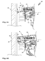
- a screw magazine attachment 10 may, as in FIG. 1 represented fixed on a screwing device 11 by means of a coupling device 12.
- the attachment 10 serves to provide and pre-promotion of screws 13 which are mounted on a strip-shaped screw magazine 14.
- the attachment 10 enables efficient and fast work, since it advances the screw magazine 14 by one position with a respective screwing of a screw 13, so that the next screw 13 is ready for screwing by means of the screwing 11.
- the screwdriver 11 is for example a cordless screwdriver or a network-connected screwdriver and can be easily grasped by the operator on an operating handle 15.
- the attachment 10 is arranged on a front side of the screwdriver 12.
- a rear side 16 of the attachment 10 is a Recording 17 on a receiving part 18 for a front end of the screwing device 11, namely a not visible in the drawing gear housing of the screwdriver 11 is provided.
- the receptacle 17 is a plug-in receptacle.
- a collar 19 of the coupling device 12 is accommodated on a main body housing 20 of a main body 21 of the attachment 10.
- a thread is present, in which a threaded portion of the receiving part 18 is screwed.
- the adjusting ring 19 is coupled for movement with an indicator part 22, which is arranged in a window 23 of the main body housing 20 and indicates the respective screw-in depth.
- the adjusting ring 19 is latching.
- a detent spring 24 engages in corresponding locking receptacles 93 on the adjusting ring 19 a.
- the main body housing 20 is constructed in two parts in the present case. Housing parts 25 are connected to each other by means of screws 26.
- the main body housing 20 has a gun-like shape. From a guide housing part 27 of the main body housing 20, which serves to guide a carriage 28, is a guide arm 29 with a main body magazine guide 30 for guiding the screw magazine 13 at an angle, in the present case approximately at right angles, from.
- the magazine guide 30 extends from the lower, free end of the guide arm 29 arcuately toward the carriage 28, which in turn also has a magazine guide 31 for guiding the screw magazine 14.
- the screws 13 are arranged successively or one behind the other.
- the screws 13 penetrate in a conventional manner, a band 32 of the screw magazine 14, wherein shanks 33 on the one hand project in front of the band 32 and on the other side of the belt 32, the heads 34 of the screws 13th issue.
- the screws 13 are screwed into a workpiece 35, their heads 34 penetrate the screw magazine belt 32.
- the two magazine guides 30, 31 each have a guide track 36, which has a longitudinal slot 37 on the front side.
- the screw magazine belt 32 is completely received in the guide track, that is, the two magazine guides 30, 31 engage over side edges 38 of the screw magazine belt 32, while the shafts 33 of the screws 13 longitudinal slots 37 of the two magazine guides 30, 31 penetrate.
- Both longitudinal slots 37 each extend from beginning to end of the magazine guide 30, 31, so that the screw magazine strip 32 equipped with the screws 13 can be pulled freely through the magazine guides 30, 31 not only in a conveying direction 39 but also in the opposite direction at least when a conveyor releases the screw magazine 14.
- the conveyor 40 is arranged substantially on the carriage 28.
- An essential component of the conveyor 40 is a conveyor pawl portion 41 which engages with engaging projections 42 in driving openings 43 on the side edges of the screw magazine belt 32 and thus the screw magazine 14 in the conveying direction 39 promotes ( FIGS. 4a-4e ).
- a slide guide 45 for guiding the carriage 28 is arranged in an inner space 44 of the main body housing 20, in particular of the guide housing part 27, a slide guide 45 for guiding the carriage 28 is arranged.
- the slide guide 45 comprises guide channels 46, which extend along a slide displacement axis 47 in the inner space 44.
- the carriage 28 is guided displaceably along the carriage displacement axis 47 on the base body 21.
- the stopper 49 has a U-shaped configuration. Side arms 50 of the stop 49 are guided longitudinally adjustable on stop guides 51 of the carriage 28, in this case of the carriage housing 48, so that an adaptation of the stopper 49 to a respective shaft length of a shaft 33 is possible.
- the stop 49 can be fixed by means of a holding device 52 in a respective longitudinal position.
- the holding device 52 comprises a locking part 53, the side arms project laterally in front of the carriage housing 48 in the region of the stop guides 51 and engage in locking receptacles 54 on the side arms 50.
- the locking member 53 can be manually pressed against the force of the locking member 54 in its locking position loading spring 55, so that the side arms of the locking member 53 out of engagement with the locking receptacles 54 and the workpiece stop 49 can be moved longitudinally.
- the side arms 50 of the workpiece stop 49 engage in the guide channels 46 and are guided in this along the carriage-displacement axis 47.
- the carriage 28 is guided linearly by means of the workpiece stop 49 on the main body 21.
- the carriage 28 is penetrated by a screwdriver tool 56 which extends parallel to the carriage-displacement axis 47 in the interior 44 of the base body 21.
- a rotary driving head of the screwdriver tool 56 is not visible in the drawing in the region of the coupling device 12 to be there rotatably coupled to the screwdriver 11.
- a shaft region 57 of the screwdriver tool 56 is guided on a tool guide 58 of the attachment 10, preferably on the one hand the coupling device 12 and on the other hand on Carriage 28.
- the screwdriver tool 56 penetrates the carriage 28, wherein a lateral guide along a carriage designed according to the invention is entirely conceivable.
- the carriage 28 When screwing in a screw 13, the carriage 28 is displaced against the force of a carriage 28 in the screwing direction loading slide spring 60 to the coupling device 12 back along the slide displacement axis 47 with respect to the base body 21.
- the slide spring 60 is supported on the one hand on the main body 21, for example on a rear wall in the region of the coupling device 12, and on the other hand on the carriage 28, for example in the region of a guide projection 61.
- the guide projection 61 penetrates into an interior of the present case designed as a helical spring spring 60 a.
- one of the two guide eyes 59 is arranged in the interior of the guide projection 61.
- the conveyor pawl part 41 is pivotable about a pawl pivot axis 62, which runs transversely, in the exemplary embodiment, at right angles to the carriage displacement axis 47.
- the pawl part 41 is mounted so as to be linearly displaceable both about the pawl pivot axis 62 and about a pawl sliding axis 63 relative to the carriage 28, in particular of the carriage housing 48.
- a type of carriage frame or slide body may be provided in an attachment according to the invention.
- the respective conveyor pawl part with respect to a carriage main body not only to the pawl pivot axis, but also to a latch axis on a respective Storage arrangement, for example in the manner of a bearing assembly 64 of the carriage 28, is mounted.
- the bearing arrangement 64 comprises bearing receptacles 65 on side walls 66 of the carriage housing 48.
- the two bearing receptacles 65 are configured in the form of oblong holes.
- the bearing receivers 65 are in the drawing downwards, that is open at a side facing away from the tool guide 58 side of the carriage 28, so that from there bearing parts of the conveyor latch part 41 can be inserted.
- bearing parts are presently formed by a sleeve 67 and a sleeve 67 penetrating Drehachs Georgia 68.
- the sleeve 67 is rotatably mounted on the conveyor pawl part 41 in a bearing receptacle 69.
- the Drehachs Indiana 68 in turn is rotatably received in the sleeve 67.
- the Drehachs Indiana 68 forms in this case a rotary shaft, at the respective ends rollers 70 are arranged.
- the rollers 70 are provided with tires 71, for example made of rubber, an elastic plastic or the like.
- the rollers 70 project laterally in front of the carriage housing 48.
- the sleeve 67 is received with their respective laterally projecting in front of the conveyor pawl portion 41 areas in the bearing seat 65 and can be linearly moved in this to the latch shaft 64.
- the conveyor pawl part 41 which can optionally also be fixedly arranged on the sleeve 67, can be pivoted about the pawl pivot axis 62 defined for the rotary axis piece 68.
- the conveyor pawl part 41 is received in a lockable by a closure member 73 receiving chamber 72 of the carriage 28.
- the side walls 66 bound the receiving chamber 72 laterally.
- the closure part 73 also closes the bearing arrangement 64, in particular the two bearing receptacles 65.
- a transverse width of the conveying pawl part 41 corresponds approximately to an inner spacing of the receiving chamber 72 in the region of the side walls 66.
- the closure member 73 also forms an abutment for a spring assembly 74 which loads the conveyor pawl member 41 in an engagement position E, in which the conveyor pawl member 41 engages the driving openings 43 of the screw magazine belt 32.
- the spring arrangement 74 comprises a spring 75, in the present case a helical spring, which is supported on the one hand on a support arm 76 of the conveyor latch part 41 and on the other hand on the inside of the closure part 73 facing the receiving chamber 72.
- a projection is arranged on the closure part 73, which penetrates into an inner space of the spring 75.
- the spring arrangement 74 also has a locking part 73 on the carriage housing 48 securing effect.
- guide projections and guide recesses are arranged with a course such that the spring 75 presses a guide projection or a plurality of guide projections against respective ends of one or more guide tracks.
- projections are arranged on the closure part 73, which engage in L-shaped, in the direction of the open side of the receiving chamber 73 ending receiving channels on the carriage housing 48.
- a projection or other support for the spring 75 is also provided on the conveyor pawl portion 41.
- the conveyor pawl member 41 can be manually adjusted from its engagement position E in a release position F, in which it does not engage in the driving openings 43 of the belt 32. Then, the band 32 can be pulled through the both sides open longitudinal slots 37 of the magazine guides 30, 31 even with screws 13 located on it.
- the conveyor pawl member 41 has an actuating arm 77 extending away from the support arm 76 and the Eingreifvorsprüngen 42 in the drawing down to a Insertion opening 78 for insertion of the conveyor pawl portion 41 extends into the receiving chamber 72 toward. There is then the free end of the actuating arm 77 actuated by an operator.
- the conveyor pawl part in side view, see for example FIG. 2a a substantially T-shaped shape.
- the bearing receiver 69 is arranged on the actuating arm 77 in the vicinity of the support arm 76.
- the conveyor pawl portion 41 pivots expediently about its center.
- the two engagement projections 42 are arranged on a base body 79 of the conveyor pawl part 41 comprising the actuating arm 77 and the support arm 76.
- the engagement projections 42 are preferably made of metal.
- the base body 79 is made of lightweight, plastically easily moldable plastic.
- the two engagement projections 42 are formed by an engagement member 80 which is fixed to the base body 79, for example by means of a screw.
- the two engagement projections 42 are fork-shaped, so that they engage on both sides, in particular next to a respective screw to be conveyed 13, in driving openings 43 on opposite edge sides of the screw magazine belt 32.
- the band 32 can be pre-conveyed tension-free and / or without jamming and seized in several places in the conveying direction 39.
- a conveyor gear 81 For actuating the conveyor pawl part 41 to a respective conveying operation of the screw magazine 14, a conveyor gear 81 is provided.
- the conveyor gear 81 comprises a slide mechanism 82, which predetermines the conveyor pawl part 41 to move up and down along the pawl slide axis 63 during a respective displacement stroke of the carriage 28.
- the conveyor pawl part 41 is on the one hand from the engagement position E in a release position F swung out, see FIG.
- the two rollers 70 which form the slide follower, roll along guide tracks 84.
- the two slide tracks 84 are provided next to the slide guide channels 46 on the base body 21.
- Both the carriage guide channels 46 and the slide track 48 are suitably made of metal, whereas the main body housing 20 is advantageously made of plastic.
- the slide tracks 84 and the slide guide channels 46 are provided by metallic insert elements 87.
- the insert elements 87 are arranged on the inner sides of the main body housing 20 in the inner space 44.
- the slide tracks 84 have the screw end of the attachment towards slanting sections and subsequently in the direction of the coupling device 12 parallel sections 86.
- the slide tracks 84 extend in the region of the parallel sections 86 parallel to the slide displacement axis 47, in the region of the oblique sections 85 at an angle thereto.
- the removal of the conveyor pawl part 41 from the carriage housing 48 is particularly simple, in which the closure part 73 is removed from the carriage housing 48 without tools.
- the carriage housing 48 or the carriage 28 can be removed just as easily and without tools from the main body 21.
- the main body housing 20 is namely open at its side facing away from the coupling device 12 screw side, so that the carriage 28 can be introduced so to speak from the front into the main body housing 20.
- a guide lock 88 for locking the carriage 28 and for holding the carriage 28 on the main body 21 and the main body housing 20 is a guide lock 88, which is manually operable. If the guide lock 88 is unlocked, the carriage 28 can be removed from the main body 21.
- the guide lock 88 includes a locking member 89 movably mounted on the carriage 28.
- the locking member 89 is defined by a window at the top of the Carriage housing 48 actuated by pressure by an operator.
- the locking member 89 is loaded in its locking position by a spring 89.
- locking projections 91 of the locking member 89 are positioned so that they abut against locking stops 92 of the base body 21 and the carriage 28 is held on the housing 28.
- the locking projections 91 and the associated locking stops 92 limit that the carriage 28 is moved out of the main body housing 20 under the load of the carriage spring 60.
- the guide lock 88 can be manually operated by pressing a button, so that a disassembly of the attachment 10 is possible without tools.
- the bearing receptacle 69 for the sleeve 67 and the Drehachs republic 68 is open at the side, so that a simple removal is possible.
- the locking members 53 and 89 are also easily accessible when the carriage 28 is moved into the main body housing 20 inside.
- the spring assembly 74 also serves to move the conveyor pawl member 41 from its remote from the screwdriver tool 56, in the drawing lower position back towards the screwdriver tool 56, namely in the context of a delivery stroke in which the conveyor pawl member 41 is in engagement position E, that is engages the screw magazine belt 32 and promotes the next screw to be screwed 13 in the direction of the screwdriver tool 56.
- the inventive alignment of the pawl pivot axis 62 proves to be advantageous in that the spring assembly 74, so to speak central between the two Eingreifvorsprüngen 42 acts on the conveyor pawl part 41, so that any tensions, jams or the like are not to be feared.
Landscapes
- Engineering & Computer Science (AREA)
- Mechanical Engineering (AREA)
- Details Of Spanners, Wrenches, And Screw Drivers And Accessories (AREA)
- Portable Nailing Machines And Staplers (AREA)
- Automatic Tool Replacement In Machine Tools (AREA)
Abstract
Description
Die Erfindung betrifft ein Schraubenmagazin-Vorsatzgerät für ein motorisch antreibbares Schraubgerät zum Einschrauben von Schrauben, mit einem mittels einer Kopplungseinrichtung an das Schraubgerät koppelbaren Grundkörper und einer Werkzeugführung zur Führung eines durch das Schraubgerät antreibbaren Schraubendreherwerkzeugs, mit einem gegen ein Werkstück abstützbaren, entlang einer Schlitten-Verschiebeachse verschiebbar an einer Schlittenführung des Grundkörpers geführten Schlitten, an dem eine Magazinführung zur Führung eines streifenförmigen, die Schrauben bereitstellenden Schraubenmagazins angeordnet ist, wobei an dem Schlitten zum Vorfördern des Schraubenmagazins eine Fördereinrichtung mit einem Förderklinkenteil angeordnet ist, das durch ein mit dem Grundkörper zusammenwirkendes Fördergetriebe bei einem Verschiebehub des Schlittens bezüglich des Grundkörpers in das Schraubenmagazin eingreift und dieses vorfördert.The invention relates to a screw magazine attachment for a motor-driven screwdriver for screwing in screws, with a coupled by means of a coupling device to the screwdriver base and a tool guide for guiding a drivable by the screwdriver tool, with a supportable against a workpiece, along a carriage Displacement axis slidably guided on a carriage guide of the body guided carriage on which a magazine guide for guiding a strip-shaped, the screws providing screw magazine is arranged, wherein on the carriage for advancing the screw magazine a conveyor with a conveyor pawl part is arranged, which cooperates by a cooperating with the main body feed gear engages in a displacement stroke of the carriage relative to the base body in the screw magazine and this promotes.
Derartige Schraubenmagazin-Vorsatzgeräte sind auf dem Gebiet der Handwerkzeugmaschinen zwischenzeitlich allgemein bekannt. Das Schraubenmagazin wird mittels einer Klinke vorgefördert, so dass nach dem Einschrauben einer ersten Schraube eine zweite, sequentiell nach dieser im Schraubenmagazin angeordnete Schraube in Front des Schraubendreherwerkzeugs gelangt. Dann kann bei einem nächsten Verschiebehub des Schlittens das Schraubendreherwerkzeug wieder in Eingriff mit der Schraube gelangen und diese in einen Untergrund einschrauben. Der Schlitten stützt sich dabei am Untergrund ab.Such screw magazine attachments are well known in the field of hand tool machines in the meantime. The screw magazine is pre-conveyed by means of a pawl, so that after screwing a first screw a second, sequentially arranged after this in the screw magazine screw gets into the front of the screwdriver tool. Then, in a next displacement stroke of the carriage, the screwdriver tool again in engagement with the screw and screw them into a base. The carriage is supported on the ground.
Ausgehend davon ist es die Aufgabe der vorliegenden Erfindung, ein Schraubenmagazin-Vorsatzgerät bereitzustellen, das eine einfache und robuste Fördereinrichtung bzw. eine Fördermechanik zum Vorfördern des Schraubenmagazins aufweist.Based on this, it is the object of the present invention to provide a screw magazine attachment, which has a simple and robust conveyor or a conveyor mechanism for advancing the screw magazine.
Zur Lösung der Aufgabe ist bei einem Schraubenmagazin-Vorsatzgerät der eingangs genannten Art vorgesehen, dass das Förderklinkenteil um eine Klinkenschwenkachse quer, insbesondere rechtwinkelig quer, zu der Schlitten-Verschiebeachse an einer Lageranordnung des Schlittens schwenkbar zwischen einer Eingreifstellung, in der das Förderklinkenteil in das Schraubenmagazin eingreift, und einer Freigabestellung gelagert ist, in der das Förderklinkenteil außer Eingriff mit dem Schraubenmagazin ist.To solve the problem is provided in a screw magazine attachment of the type mentioned that the conveyor pawl part about a pawl pivot axis, in particular perpendicular transversely to the carriage-displacement axis of a bearing assembly of the carriage pivotally between an engagement position in which the conveyor pawl part in the screw magazine engages, and is mounted in a release position in which the conveyor pawl part is out of engagement with the screw magazine.
Ein Grundgedanke der Erfindung ist, dass das Förderklinkenteil zweckmäßigerweise eine Art Pendelbewegung zwischen der Eingreifstellung und der Freigabestellung durchführt. Die Klinkenschwenkachse bzw. Pendelachse verläuft quer, vorzugsweise rechtwinkelig quer, zur Schlitten-Verschiebeachse. Dadurch ist es beispielsweise möglich, dass das Förderklinkenteil an mehreren Stellen, vorzugsweise zwei Stellen, in das Schraubenmagazin eingreift, wenn es dieses vorfördert. Dadurch ist ein Verklemmen oder Verspannen des Schraubenmagazins in der Magazinführung effektiv zu vermeiden. Weiterhin ist eine platzsparende Bauweise dahingehend möglich, dass das Förderklinkenteil nicht beispielsweise seitlich vom Schlitten wegschwenkt, wofür beispielsweise ein entsprechender Bauraum seitlich neben dem Schlitten am Grundkörper oder ein Freiraum für die Ausschwenkbewegung vorgesehen sein muss. Vielmehr ist es erfindungsgemäß möglich, dass das Förderklinkenteil beispielsweise innerhalb des Schlittens schwenkt. Weiterhin erlaubt die erfindungsgemäße Anordnung des Förderklinkelteils, dass dieses bequem von der Eingreifstellung in die Freigabestellung geschwenkt werden kann, so dass ein Bediener das Schraubenmagazin verschieben kann. Die Fördereinrichtung gibt nämlich dann das Schraubenmagazin vorteilhaft vollständig frei.A basic idea of the invention is that the conveyor pawl part expediently performs a kind of oscillating movement between the engagement position and the release position. The pawl pivot axis or pendulum axis runs transversely, preferably at right angles, to the carriage displacement axis. This makes it possible, for example, that the conveyor pawl part at several points, preferably two places, engages in the screw magazine, if it promotes this. This effectively prevents jamming or distortion of the screw magazine in the magazine guide. Furthermore, a space-saving design is possible to the effect that the conveyor pawl part, for example, not laterally pivots away from the carriage, for which, for example, a corresponding space must be provided laterally next to the carriage on the body or a free space for Ausschwenkbewegung. Rather, it is possible according to the invention that the conveyor pawl part, for example swings inside the carriage. Furthermore, the arrangement according to the invention allows the conveying angle part that this can be conveniently pivoted from the engagement position to the release position, so that an operator can move the screw magazine. Namely, the conveyor is then advantageously completely free the screw magazine.
Der Grundkörper ist zweckmäßigerweise feststehend mit dem Schraubgerät koppelbar. Dafür ist beispielsweise eine Koppelaufnahme am Schraubenmagazin-Vorsatzgerät zur Aufnahme eines Abtriebsteils des Schraubgeräts vorhanden.The main body is expediently coupled fixedly with the screwdriver. For example, there is a coupling receptacle on the screw magazine attachment for receiving a driven part of the screwdriver.
Weiterhin ist vorteilhaft, wenn am Grundkörper eine Schraubenmagazin-Führung für das Schraubenmagazin angeordnet ist, so dass das Schraubenmagazin sowohl an der Führung des Grundkörpers als auch an der Magazinführung des Schlittens geführt ist.Furthermore, it is advantageous if a screw magazine guide for the screw magazine is arranged on the base body, so that the screw magazine is guided both on the guide of the main body and on the magazine guide of the carriage.
Zwar könnte das Förderklinkenteil in der Art eines Ritzels ausgestaltet sein. Bevorzugt ist jedoch eine Ausführungsform, bei der das Förderklinkenteil als ein Klinkelhebel ausgestaltet ist oder einen Klinkenhebel umfasst.Although the conveyor pawl part could be designed in the manner of a pinion. However, an embodiment in which the conveyor pawl part is designed as a latch lever or comprises a latch lever is preferred.
Wie eingangs bereits erwähnt, hat das Förderklinkenteil zweckmäßigerweise mindestens zwei oder genau zwei Eingreifvorsprünge zum simultanen Eingriff in das Schraubenmagazin, zweckmäßigerweise an einander entgegengesetzten Seiten einer jeweils zu fördernden Schraube. Die Eingreifvorsprünge sind zweckmäßigerweise parallel zu der Klinkenschwenkachse angeordnet. Die Eingreifvorsprünge sind vorteilhaft gabelartig ausgestaltet. Somit kann das Förderklinkenteil in der Art einer Gabel in das Schraubenmagazin bzw. dort zweckmäßigerweise vorgesehene Ausnehmungen eingreifen.As already mentioned, the conveyor pawl expediently has at least two or exactly two engagement projections for simultaneous engagement in the screw magazine, expediently on mutually opposite sides of a respective screw to be conveyed. The engagement projections are expediently arranged parallel to the pawl pivot axis. The engagement projections are advantageously designed like a fork. Thus, the conveyor pawl part in the manner of a fork in the screw magazine or there expediently provided recesses engage.
Vorteilhaft ist das Förderklinkenteil in die Eingreifstellung durch eine Federanordnung federbelastet. Die Federanordnung umfasst beispielsweise eine Spiralfeder aus Metall. An dieser Stelle sei erwähnt, dass das Förderklinkenteil auch durch das Fördergetriebe des Vorsatzgerätes von der Eingreifstellung in die Freigabestellung und/oder umgekehrt geschwenkt werden kann, auch wenn dies beim Ausführungsbeispiel nicht der Fall ist. Die federbelastete Variante hat den Vorteil, dass das Förderklinkenteil aufgrund der Belastung durch die Federanordnung in das Schraubenmagazin eingreift, sofern dem Förderklinkenteil eine Eingriffaufnahme des Schraubenmagazins gegenüberliegt.Advantageously, the conveyor pawl part is spring-loaded in the engagement position by a spring arrangement. The spring arrangement comprises, for example, a spiral spring made of metal. At this point it should be mentioned that the conveyor pawl part can also be pivoted by the conveyor gear of the attachment from the engagement position to the release position and / or vice versa, even if this is not the case in the embodiment. The spring-loaded variant has the advantage that the conveyor pawl part engages due to the load of the spring assembly in the screw magazine, if the conveyor pawl part facing an engagement receiving the screw magazine.
Mindestens ein Eingreifvorsprung, zweckmäßigerweise alle Eingreifvorsprünge, des Schraubenmagazin-Vorsatzgerätes zum Eingriff in das Schraubenmagazin und ein Stützanschlag zum Abstützen der Federanordnung sind zweckmäßigerweise an einander entgegengesetzten Seiten des Förderklinkenteils angeordnet. Es versteht sich, dass der oder die Eingreifvorsprünge auch unmittelbar durch die Federanordnung belastet sein können, was beim Ausführungsbeispiel jedoch nicht realisiert ist.At least one engagement projection, suitably all engagement projections, of the screw magazine attachment for engagement in the screw magazine and a support stop for supporting the spring arrangement are expediently arranged on opposite sides of the conveyor latch member. It is understood that the one or more engagement projections may also be loaded directly by the spring arrangement, which is not realized in the embodiment.
Das Förderklinkenteil hat zweckmäßigerweise mindestens eine Bedienhandhabe zur manuellen Betätigung zwischen der Eingreifstellung und der Freigabestellung. Beispielsweise hat das Förderklinkenteil eine T-förmige Gestalt, wobei einander entgegengesetzte Seitenarm mindestens einen Eingreifvorsprung und einen Stützanschlag für die Federanordnung bilden, während ein zwischen den Seitenarmen angeordneter Arm die Bedienhandhabe aufweist oder bildet. Es versteht sich, dass auch bei einer balkenartigen Ausgestaltung des Förderklinkenteils eine manuelle Bedienhandhabe möglich ist, beispielsweise an einer vom Eingreifvorsprung abgewandten Seite des Förderklinkenteils. An dieser Stelle sei bemerkt, dass das Förderklinkenteil einstückig sein kann, jedoch auch in einer anderen Ausgestaltung mehrere Komponenten aufweisen kann. So sind insbesondere der oder die Eingreifvorsprünge aus Metall, während andere Bauteilbereiche, beispielsweise die Bedienhandhabe, mechanisch geringer belastet sind und dementsprechend vorteilhaft aus Kunststoff ausgebildet sind.The conveyor pawl part expediently has at least one operating handle for manual actuation between the engagement position and the release position. For example, the conveyor pawl member has a T-shaped configuration, opposite side arms forming at least one engagement projection and a support stop for the spring arrangement, while an arm disposed between the side arms comprises or forms the operating handle. It is understood that even with a bar-like configuration of the conveyor latch part, a manual operating handle is possible, for example, on a side facing away from the engagement projection side of the conveyor latch part. It should be noted that the conveyor pawl part may be integral, but also in another embodiment a plurality Components may have. Thus, in particular the or the engagement projections made of metal, while other component areas, such as the operating handle, are mechanically less loaded and are therefore advantageously made of plastic.
Die Klinkenschwenkachse bildet vorzugsweise eine Drehachse eines Drehteils des Fördergetriebes. Das Drehteil ist beispielsweise mindestens ein Zahnrad, mindestens eine Rolle oder dergleichen.The pawl pivot axis preferably forms an axis of rotation of a rotary part of the conveyor gear. The rotary part is for example at least one gear, at least one roller or the like.
Das Förderklinkenteil ist vorzugsweise schwenkbar an einem das Drehteil drehbar lagernden Drehachsstück gelagert. Mithin kann also das Förderklinkenteil um das Drehachsstück schwenken. Das Drehachsstück kann in bevorzugten Ausgestaltung der Erfindung eine Drehachse sein, an deren Längsendbereichen jeweils ein Drehteil, insbesondere eine Rolle oder ein Zahnrad, fest oder drehbar angeordnet ist.The conveyor pawl part is preferably mounted pivotably on a rotary axle which rotatably supports the rotary part. Thus, therefore, the conveyor pawl part can pivot about the Drehachsstück. The Drehachsstück may be a rotation axis in the preferred embodiment of the invention, at the longitudinal end of each of which a rotary member, in particular a roller or a gear, is fixed or rotatable.
Das Förderklinkenteil ist zweckmäßigerweise an einer von dem Drehachsstück durchdrungenen, bezüglich des Drehachsstücks drehbaren Hülse angeordnet. An dieser Hülse ist das Förderklinkenteil vorzugsweise drehbar angeordnet, wobei eine feststehende Anordnung an dieser Hülse ebenfalls möglich ist. Die Hülse erstreckt sich vorzugsweise zwischen den beiden vorgenannten Drehteilen, beispielsweise den Rollen oder beim Ausführungsbeispiel nicht realisierten Zahnrädern.The conveyor pawl part is expediently arranged on a sleeve penetrated by the rotary axis piece and rotatable relative to the rotary axis piece. On this sleeve, the conveyor pawl member is preferably rotatably arranged, wherein a fixed arrangement of this sleeve is also possible. The sleeve preferably extends between the two aforementioned rotary parts, for example, the rollers or unrealized in the embodiment gears.
Das Förderklinkenteil ist vorzugsweise in einer Aufnahme, beispielsweise einer Aufnahmekammer, des Schlittens angeordnet. Diese Aufnahme ist zweckmäßigerweise mittels eines Verschlussteils verschließbar. Das Verschlussteil ist in einer bevorzugten Variante werkzeuglos betätigbar. Das erleichtert eine werkzeuglose Demontage des Schraubenmagazin-Vorsatzgerätes, beispielsweise zu Wartungszwecken und/oder wenn sich ein Bauteil verklemmt hat.The conveyor pawl part is preferably arranged in a receptacle, for example a receiving chamber, of the carriage. This receptacle is expediently closable by means of a closure part. The closure part is operated without tools in a preferred variant. This facilitates a tool-free disassembly of the screw magazine attachment, for example, for maintenance and / or if a component has jammed.
Der Grundkörper und/oder der Schlitten weisen zweckmäßigerweise jeweils ein Gehäuse auf. Im Gehäuse des Schlittens kann die vorgenannte Aufnahmekammer für das Förderklinkenteil angeordnet sein. Es versteht sich, dass alternativ auch eine gestellartige Ausgestaltung sowohl des Schlittens als auch des Grundkörpers prinzipiell möglich sind.The main body and / or the carriage expediently each have a housing. In the housing of the carriage, the aforementioned receiving chamber may be arranged for the conveyor latch part. It is understood that alternatively a frame-like configuration of both the carriage and the base body are possible in principle.
Das Verschlussteil für die Aufnahme oder die Aufnahmekammer bildet zweckmäßigerweise ein Widerlager für die Federanordnung oder umfasst ein solches Widerlager. Somit kann also die Federspannung unmittelbar durch Entfernen des Verschlussteils aufgehoben werden, was eine Demontage erleichtert.The closure part for the receptacle or the receiving chamber expediently forms an abutment for the spring arrangement or comprises such an abutment. Thus, therefore, the spring tension can be canceled directly by removing the closure part, which facilitates disassembly.
Die Lageranordnung lagert das Förderklinkenteil zweckmäßigerweise nicht nur schwenkbar, sondern auch verschieblich. Dies ist beispielsweise mittels einem oder mehrerer Langlöcher realisierbar. Das oder die Länglöcher können wie beim Ausführungsbeispiel einen geraden, aber auch einen gekrümmten Verlauf oder Abschnitt aufweisen. Mithin kann also mit Hilfe des Langloches eine Bewegungsbahn des Förderklinkenteils relativ zum Schlitten vorgebbar sein.The bearing assembly stores the conveyor pawl expediently not only pivotable, but also displaceable. This can be realized for example by means of one or more slots. The one or more elongated holes may, as in the exemplary embodiment, have a straight course, but also a curved course or section. Thus, therefore, with the help of the elongated hole, a movement path of the conveyor latch part relative to the carriage can be specified.
Die Lageranordnung zur Lagerung des Förderklinkenteils ist zweckmäßigerweise an einer Seite offen und kann mittels eines Verschlussteils verschließbar sein. Die Lageranordnung nimmt beispielsweise das Drehachsstück auf. Bevorzugt ist es, wenn die Lageranordnung mindestens ein, vorzugsweise zwei seitlich offene Langlöcher aufweist. Das Förderklinkenteil ist vorzugsweise zwischen den vorgenannten Langlöchern angeordnet.The bearing arrangement for mounting the conveyor pawl part is expediently open on one side and can be closed by means of a closure part. The bearing assembly, for example, receives the Drehachsstück. It is preferred if the bearing arrangement has at least one, preferably two laterally open slots. The conveyor pawl part is preferably arranged between the aforementioned oblong holes.
Bevorzugt ist es, wenn das Fördergetriebe ein Kulissengetriebe umfasst und eine Kulissenbahn an dem Grundkörper und ein Kulissenfolger, beispielsweise eine Rolle, Walze oder dergleichen, am Schlitten angeordnet ist. Bevorzugt sind zwei Kulissenbahnen, zwischen denen der Schlitten zumindest bei einem Teilabschnitt während des Verschiebens entlang der Schlitten-Verschiebachse angeordnet ist. Der Kulissenfolger könnte beispielsweise ein Gleitstück sein. Bevorzugt ist der Kulissenfolger oder sind die Kulissenfolger zweckmäßigerweise Drehteile, beispielsweise Rollen, Zahnräder oder dergleichen. Mithin ist also der Kulissenfolger in einer bevorzugten Variante drehbar am Schlitten gelagert.It is preferred if the conveyor gear comprises a sliding gear and a slide track on the base body and a slide follower, for example a roller, roller or the like, is arranged on the carriage. Preference is given to two slide tracks, between which the carriage is arranged at least at a partial section during the displacement along the slide displacement axis. The gate follower could for example be a slider. Preferably, the slide follower or the slide followers are expediently turned parts, such as rollers, gears or the like. Thus, therefore, the link follower is rotatably mounted on a carriage in a preferred variant.
Das Fördergetriebe, beispielsweise die vorgenannte Kulissenbahn, gibt dem Förderklinkenteil bei einem jeweiligen Verschiebehub zweckmäßigerweise eine Hoch-Tiefbewegung vor, bei der das Förderklinkenteil an dem Schraubenmagazin in Richtung einer nächsten vorzufördernde Schraube entlang bewegt wird. Beispielsweise hat die Kulissenbahn dazu einen winkelig, zweckmäßigerweise schräg zur Schlitten-Verschiebeachse verlaufenden Schrägabschnitt. Das Förderklinkenteil gleitet zweckmäßigerweise bei dieser Hoch-Tiefbewegung, vorzugsweise entgegen der Kraft einer Federanordnung, besonders bevorzugt der Kraft der sie in Richtung des Schraubenmagazins belastenden Federanordnung, entlang, bis es in die nächste Mitnahmeöffnung des Schraubenmagazins einklinken oder einrasten kann.The conveyor gear, for example, the aforementioned slide track, the conveyor pawl part at a respective displacement stroke expediently before a high-low motion in which the conveyor pawl member is moved to the screw magazine in the direction of a next vorzufördernde screw along. For example, the slide track has an angular, suitably obliquely extending to the slide-displacement axis oblique section. The conveyor pawl part expediently slides along this high-depth movement, preferably against the force of a spring arrangement, particularly preferably the force of the spring assembly loading it in the direction of the screw magazine, until it can latch or latch into the next catch opening of the screw magazine.
Zweckmäßigerweise ist vorgesehen, dass das Schraubendreherwerkzeug das Schraubenmagazin bei einem Schwenken des Förderklinkenteils aus der Eingreifstellung in die Freigabestellung und/oder während der Hoch-Tiefbewegung des Förderklinkenteils festlegt. Somit ist es möglich, dass das Förderklinkenteil außer Eingriff mit dem Schraubenmagazin gelangt, ohne dass dieses sich weiterbewegt. Beispielsweise durchdringt das Schraubendreherwerkzeug das Schraubenmagazin. Aber auch bereits dann, wenn das Schraubendreherwerkzeug lediglich in den Kopf der jeweiligen Schraube eindringt, wird diese entgegen einer Förderbewegung festgelegt. Das Fördergetriebe ist zweckmäßigerweise so ausgestaltet, dass es dem Förderklinkenteil die Hoch-Tiefbewegung erst dann vorgibt, wenn das Schraubendreherwerkzeug im Eingriff mit einer Schraube und/oder einem Schraubenmagazin ist, das heißt also wenn das Schraubendreherwerkzeug das Schraubenmagazin entgegen einer Förderbewegung festlegt. Dies ist vorzugsweise so realisiert, dass der vorgenannte Kulissenfolger erst dann zu einem die Hoch-Tiefbewegung vorgebenden Abschnitt der Kulissenbahn gelangt, z.B. dem Schrägabschnitt, wenn das Schraubendreherwerkzeug im Eingriff mit einer Schraube und/oder dem Schraubenmagazin ist, jedenfalls wenn das Schraubendreherwerkzeug das Schraubenmagazin festlegt.Appropriately, it is provided that the screwdriver tool sets the screw magazine upon pivoting of the conveyor latch part from the engagement position into the release position and / or during the high-low movement of the conveyor latch part. Thus, it is possible that the conveyor pawl part disengages from the screw magazine, without this continues to move. For example The screwdriver tool penetrates the screw magazine. But even then, when the screwdriver tool only penetrates into the head of the respective screw, it is set against a conveying movement. The conveyor gear is expediently designed so that the conveyor pawl part only determines the high-low motion when the screwdriver tool is in engagement with a screw and / or a screw magazine, that is, when the screwdriver tool sets the screw magazine against a conveying movement. This is preferably realized so that the aforementioned gate follower only then reaches a section of the slide track which predetermines the high-deep movement, eg the inclined section, when the screwdriver tool is in engagement with a screw and / or the screw magazine, at least if the screwdriver tool determines the screw magazine ,
An dieser Stelle sei bemerkt, dass auch durch andere Maßnahmen eine Festlegung des Schraubenmagazins während einer Hoch-Tiefbewegung und/oder einer Schwenkbewegung des Förderklinkenteils realisiert sein kann, beispielsweise durch entsprechende Eingreifvorsprünge, die zweckmäßigerweise durch das Fördergetriebe betätigt werden.At this point it should be noted that by other measures a determination of the screw magazine during a high-deep movement and / or a pivoting movement of the conveyor pawl part can be realized, for example by appropriate Eingreifvorsprünge, which are suitably operated by the conveyor gear.
Der Schlitten ist zweckmäßigerweise in einer Einschraubrichtung federbelastet.The carriage is expediently spring-loaded in a screwing-in direction.
Im Sinne eines werkzeuglosen Montage- und/oder Demontagekonzeptes ist es vorteilhaft, wenn das Schraubenmagazin-Vorsatzgerät eine manuell betätigbare, insbesondere am Schlitten angeordnete Führungsverriegelung zum Halten des Schlittens in der Schlittenführung des Grundkörpers aufweist. Es versteht sich, dass die Führungsverriegelung auch am Grundkörper angeordnet sein kann. Zweckmäßigerweise ist die Führungsverriegelung in die Verriegelungsstellung federbelastet, alternativ wäre auch denkbar, dass die Führungsverriegelung beispielsweise zwischen einer Verriegelungsstellung und einer Freigabestellung rastbar ist. Die Schlittenführung ist zweckmäßigerweise an einer zur Kupplungseinrichtung entgegengesetzten Seite offen, was zur Entnahme bzw. Aufnahme des Schlittens vorteilhaft ist.In terms of a tool-free assembly and / or disassembly concept, it is advantageous if the screw magazine attachment has a manually operable, in particular arranged on the carriage guide lock for holding the carriage in the carriage guide of the body. It is understood that the guide lock can also be arranged on the base body. Conveniently, the guide lock spring-loaded in the locking position, alternatively, it would also be conceivable that the guide lock, for example, between a locking position and a release position can be latched. The carriage guide is expediently open at a side opposite the coupling device, which is advantageous for removing or receiving the carriage.
Der Schlitten hat zweckmäßigerweise mindestens zwei Werkzeugführungen für das Schraubendreherwerkzeug. Die Führungen können beispielsweise seitlich offene Führungen sein, sind jedoch vorzugsweise Führungsaugen. Diese Maßnahme trägt zu einer optimalen Führung des Schraubendreherwerkzeuges am Schlitten bei.The carriage expediently has at least two tool guides for the screwdriver tool. The guides may be, for example, laterally open guides, but are preferably guide eyes. This measure contributes to an optimal guidance of the screwdriver tool on the carriage.
Die Magazinführung des Schlittens hat zweckmäßigerweise einen an ihren beiden Enden offenen, von den Schrauben durchdringbaren Längsschlitz. Somit ist das Schraubenmagazin in einander entgegengesetzten Richtungen frei beweglich und kann so in jeder Richtung aus dem Schraubenmagazin-Vorsatzgerät entnommen werden.The magazine guide of the carriage expediently has an open at both ends, penetratable by the screws longitudinal slot. Thus, the screw magazine is freely movable in opposite directions and can be removed in any direction from the screw magazine attachment.
Nachfolgend wird ein Ausführungsbeispiel der Erfindung anhand der Zeichnung erläutert. Es zeigen:
- Figur 1
- eine perspektivische Schrägansicht eines Schrau- benmagazin-Vorsatzgerätes gemäß der Erfindung in einem an ein Schraubgerät angebauten Zustand,
- Figur 2a
- eine Explosionsdarstellung des Schraubenmaga- zin-Vorsatzgeräts gemäß
Figur 1 , - Figur 2b
- ein Förderklinkenteil des Schraubenmaga- zin-Vorsatzgeräts gemäß
Figur 2a in vergrößerter Darstellung, - Figur 3a
- ein Drehachsstück mit seitlich angeordneten Rollen des Schraubenmagazin-Vorsatzgerätes gemäß
Figuren 1, 2 in perspektivischer Ansicht und in - Figur 3b
- im Längsquerschnitt und
- Figuren 4 - 4e
- einen teilweisen Längsschnitt des Schraubenmaga- zin-Vorsatzgeräts gemäß
Figur 1 , etwa entsprechend einem Ausschnitt A inFigur 1 , wobeiFigur 4a den Beginn eines Schraubvorganges zeigt, der inFigur 4e ab- geschlossen ist und zur Vorförderung einer nächsten Schraube führt.
- FIG. 1
- 3 is an oblique perspective view of a screw magazine attachment according to the invention in a state attached to a screwdriver;
- FIG. 2a
- an exploded view of the screw magazine attachment according to
FIG. 1 . - FIG. 2b
- a conveyor pawl part of the screw magazine attachment according to
FIG. 2a in an enlarged view, - FIG. 3a
- a Drehachsstück with laterally disposed rollers of the screw magazine attachment according to
FIGS. 1, 2 in perspective view and in - FIG. 3b
- in longitudinal section and
- Figures 4 - 4e
- a partial longitudinal section of the screw magazine attachment according to
FIG. 1 , approximately corresponding to a section A inFIG. 1 , in whichFIG. 4a shows the beginning of a screwing, inFigure 4e is completed and leads to advancement of a next screw.
Ein Schraubenmagazin-Vorsatzgerät 10 kann wie in
Das Vorsatzgerät 10 ist an einer Vorderseite des Schraubgeräts 12 angeordnet. An einem Rückseite 16 des Vorsatzgeräts 10 ist eine Aufnahme 17 an einem Aufnahmeteil 18 für ein vorderes Ende des Schraubgeräts 11, nämlich ein in der Zeichnung nicht sichtbares Getriebegebäuse des Schraubgeräts 11 vorgesehen. Die Aufnahme 17 ist eine Steckaufnahme. Ein Stellring 19 der Kopplungseinrichtung 12 ist an einem Grundkörpergehäuse 20 eines Grundkörpers 21 des Vorsatzgerätes 10 aufgenommen.The
An der Innenseite des Stellrings 19 ist ein Gewinde vorhanden, in das ein Gewindeabschnitt des Aufnahmeteils 18 eingeschraubt ist. Durch Drehen des Stellrings 19 kann eine Einschraubtiefe festgelegt werden. Der Stellring 19 ist mit einem Indikatorteil 22 bewegungsgekoppelt, das in einem Fenster 23 des Grundkörpergehäuses 20 angeordnet ist und die jeweilige Einschraubtiefe anzeigt. Zudem ist der Stellring 19 rastend. Eine Rastfeder 24 greift in korrespondierende Rastaufnahmen 93 am Stellring 19 ein.On the inside of the adjusting
Das Grundkörpergehäuse 20 ist vorliegend zweiteilig aufgebaut. Gehäuseteile 25 sind mittels Schrauben 26 miteinander verbunden.The
Das Grundkörpergehäuse 20 hat eine pistolenartige Gestalt. Von einem Führungsgehäuseteil 27 des Grundkörpergehäuses 20, das zum Führen eines Schlittens 28 dient, steht ein Führungsarm 29 mit einer Grundkörper-Magazinführung 30 zur Führung des Schraubenmagazins 13 winkelig, vorliegend etwa rechtwinkelig, ab. Die Magazinführung 30 erstreckt sich vom unteren, freien Ende des Führungsarms 29 bogenförmig hin zu dem Schlitten 28, der seinerseits ebenfalls eine Magazinführung 31 zur Führung des Schraubenmagazins 14 aufweist.The
In dem Schraubenmagazin 14 sind die Schrauben 13 nacheinander bzw. hintereinander angeordnet. Die Schrauben 13 durchdringen in an sich bekannter Weise ein Band 32 des Schraubenmagazins 14, wobei Schäfte 33 einerseits vor das Band 32 vorstehen und auf der anderen Seite des Bandes 32 die Köpfe 34 der Schrauben 13 anliegen. Wenn die Schrauben 13 in ein Werkstück 35 eingeschraubt werden, durchdringen deren Köpfe 34 das Schraubenmagazin-Band 32.In the
Die beiden Magazinführungen 30, 31 weisen jeweils eine Führungsbahn 36 auf, die vorderseitig einen Längsschlitz 37 hat. Das Schraubenmagazin-Band 32 ist vollständig in der Führungsbahn aufgenommen, das heißt die beiden Magazinführungen 30, 31 übergreifen Seitenränder 38 des Schraubenmagazin-Bandes 32, während die Schäfte 33 der Schrauben 13 Längsschlitze 37 der beiden Magazinführungen 30, 31 durchdringen. Beide Längsschlitze 37 erstrecken sich jeweils von Anfang bis Ende der Magazinführung 30, 31, so dass das mit den Schrauben 13 bestückte Schraubenmagazin-Band 32 nicht nur in einer Förderrichtung 39, sondern auch in Gegenrichtung dazu frei durch die Magazinführungen 30, 31 gezogen werden kann, jedenfalls dann, wenn eine Fördereinrichtung das Schraubenmagazin 14 freigibt.The two magazine guides 30, 31 each have a
Die Fördereinrichtung 40 ist im Wesentlichen am Schlitten 28 angeordnet. Ein wesentlicher Bestandteil der Fördereinrichtung 40 ist einer Förderklinkenteil 41, das mit Eingreifvorsprüngen 42 in Mitnahmeöffnungen 43 an den Seitenrändern des Schraubenmagazin-Bands 32 eingreift und so das Schraubenmagazin 14 in Förderrichtung 39 vorfördert (
In einem Innenraum 44 des Grundkörpergehäuses 20, insbesondere des Führungsgehäuseteils 27 ist eine Schlittenführung 45 zur Führung des Schlittens 28 angeordnet. Die Schlittenführung 45 umfasst Führungskanäle 46, die sich entlang einer Schlitten-Verschiebeachse 47 im Innenraum 44 erstrecken. Der Schlitten 28 ist entlang der Schlitten-Verschiebeachse 47 am Grundkörper 21 verschiebbar geführt.In an
An einem Schlittengehäuse 48 des Schlittens 28 ist ein zur Abstützung am Werkstück 35 vorgesehener Werkstück-Anschlag 49 verschieblich gelagert. Der Anschlag 49 hat eine U-förmige Gestalt. Seitenarme 50 des Anschlags 49 sind an Anschlagführungen 51 des Schlittens 28, vorliegend des Schlittengehäuses 48, längsverstellbar geführt, so dass eine Anpassung des Anschlags 49 an eine jeweilige Schaftlänge eines Schaftes 33 möglich ist. Der Anschlag 49 ist mittels einer Haltevorrichtung 52 in einer jeweiligen Längsposition festlegbar. Die Haltevorrichtung 52 umfasst ein Verriegelungsteil 53, dessen Seitenarme seitlich vor das Schlittengehäuse 48 im Bereich der Anschlagführungen 51 vorstehen und in Verriegelungsaufnahmen 54 an den Seitenarmen 50 eingreifen. Das Verriegelungsteil 53 kann manuell entgegen der Kraft einer das Verriegelungsteil 54 in seine Verriegelungsstellung belastenden Feder 55 gedrückt werden, so dass die Seitenarme des Verriegelungsteils 53 außer Eingriff mit den Verriegelungsaufnahmen 54 gelangen und der Werkstück-Anschlag 49 längsverstellt werden kann.On a
Die Seitenarme 50 des Werkstück-Anschlags 49 greifen in die Führungskanäle 46 und sind in diesen längs der Schlitten-Verschiebeachse 47 geführt. Mithin ist also der Schlitten 28 mittels des Werkstück-Anschlags 49 am Grundkörper 21 linear geführt.The
Der Schlitten 28 wird von einem Schraubendreherwerkzeug 56 durchdrungen, das sich parallel zur Schlitten-Verschiebeachse 47 im Innenraum 44 des Grundkörpers 21 erstreckt. Ein Drehmitnahmekopf des Schraubendreherwerkzeugs 56 befindet sich in der Zeichnung nicht sichtbar im Bereich der Kopplungseinrichtung 12, um dort drehfest mit dem Schraubgerät 11 gekoppelt zu werden. Ein Schaftbereich 57 des Schraubdreherwerkzeugs 56 ist an einer Werkzeugführung 58 des Vorsatzgeräts 10 geführt, vorzugsweise einerseits der Kopplungseinrichtung 12 und andererseits am Schlitten 28. Dort sind zur optimalen Führung des Schraubendreherwerkzeugs 56 zwei Führungsaugen 59 vorhanden. Mithin durchdringt das Schraubendreherwerkzeug 56 den Schlitten 28, wobei ein seitliche Führung an einem erfindungsgemäß ausgestalteten Schlitten entlang durchaus denkbar ist.The
Bei einem Einschrauben einer Schraube 13 wird der Schlitten 28 entgegen der Kraft einer den Schlitten 28 in Einschraub-richtung belastenden Schlittenfeder 60 zur Kopplungseinrichtung 12 hin entlang der Schlitten-Verschiebeachse 47 bezüglich des Grundkörpers 21 verstellt. Die Schlittenfeder 60 stützt sich einerseits am Grundkörper 21, beispielsweise an einer Rückwand im Bereich der Kopplungseinrichtung 12, und andererseits am Schlitten 28 ab, beispielsweise im Bereich eines Führungsvorsprungs 61. Der Führungsvorsprung 61 dringt in einen Innenraum der vorliegend als Schraubenfeder ausgestalteten Feder 60 ein. Zudem ist im Innenraum des Führungsvorsprungs 61 eines der beiden Führungsaugen 59 angeordnet.When screwing in a
Das Förderklinkenteil 41 ist um eine Klinkenschwenkachse 62 schwenkbar, die quer, beim Ausführungsbeispiel rechtwinkelig quer, zur Schlitten-Verschiebeachse 47 verläuft. Das Klinkenteil 41 ist sowohl um die Klinkenschwenkachse 62, als auch um eine Klinkenschiebeachse 63 bezüglich des Schlittens 28, insbesondere des Schlittengehäuses 48 linear verschieblich gelagert.The conveyor pawl
An dieser Stelle sei bemerkt, dass an Stelle eines Schlittengehäuses in der Art des Schlittengehäuses 48 auch eine Art Schlittengestell oder Schlittenkörper bei einem erfindungsgemäßen Vorsatzgerät vorgesehen sein kann. Jedenfalls ist es vorteilhaft, wenn das jeweilige Förderklinkenteil bezüglich eines Schlittengrundkörpers nicht nur um die Klinkenschwenkachse, sondern auch um eine Klinkenschiebeachse an einer jeweiligen Lagerordnung, beispielsweise in der Art einer Lageranordnung 64 des Schlittens 28, gelagert ist.It should be noted that instead of a carriage housing in the manner of the
Die Lageranordnung 64 umfasst Lageraufnahmen 65 an Seitenwänden 66 des Schlittengehäuses 48. Die beiden Lageraufnahmen 65 sind in der Gestalt von Langlöchern ausgestaltet. Die Lager-aufnahmen 65 sind in der Zeichnung nach unten hin, das heißt an einer von der Werkzeugführung 58 abgewandten Seite des Schlittens 28 offen, so dass von dort her Lagerteile des Förderklinkenteils 41 einführbar sind.The bearing
Diese Lagerteile sind vorliegend durch eine Hülse 67 und ein die Hülse 67 durchdringendes Drehachsstück 68 gebildet. Die Hülse 67 ist in einer Lageraufnahme 69 drehbar am Förderklinkenteil 41 gelagert. Das Drehachsstück 68 seinerseits ist drehbar in der Hülse 67 aufgenommen. Das Drehachsstück 68 bildet vorliegend eine Drehwelle, an deren jeweiligen Enden Rollen 70 angeordnet sind. Die Rollen 70 sind mit Reifen 71 versehen, beispielsweise aus Gummi, einem elastischen Kunststoff oder dergleichen. Die Rollen 70 stehen seitlich vor das Schlittengehäuse 48 vor. Die Hülse 67 ist mit ihren jeweils vor das Förderklinkenteil 41 seitlich vorstehenden Bereichen in den Lageraufnahme 65 aufgenommen und kann in diesen um die Klinkenschiebeachse 64 linear verschoben werden. Zudem ist das Förderklinkenteil 41, das optional auch fest an der Hülse 67 angeordnet sein kann, um die das Drehachsstück 68 definierte Klinkenschwenkachse 62 schwenkbar.These bearing parts are presently formed by a
Das Förderklinkenteil 41 ist in einer durch ein Verschlussteil 73 verschließbaren Aufnahmekammer 72 des Schlittens 28 aufgenommen. Die Seitenwände 66 begrenzen die Aufnahmekammer 72 seitlich. Das Verschlussteil 73 verschließt zudem die Lageranordnung 64, insbesondere die beiden Lageraufnahmen 65. Eine Querbreite des Förderklinkenteils 41 entspricht etwa einem Innenabstand der Aufnahmekammer 72 im Bereich der Seitenwände 66. Das Verschlussteil 73 bildet zudem ein Widerlager für eine Federanordnung 74, die das Förderklinkenteil 41 in eine Eingreifstellung E belastet, in der das Förderklinkenteil 41 in die Mitnahmeöffnungen 43 des Schraubenmagazin-Bandes 32 eingreift. Die Federanordnung 74 umfasst eine Feder 75, vorliegend eine Schraubenfeder, die sich einerseits an einem Stützarm 76 des Förderklinkenteils 41 und andererseits an der der Aufnahmekammer 72 zugewandten Innenseite des Verschlussteils 73 abstützt. Vorzugsweise ist am Verschlussteil 73 ein Vorsprung angeordnet, der in einen Innenraum der Feder 75 eindringt.The conveyor pawl
Die Federanordnung 74 hat zudem eine das Verschlussteil 73 am Schlittengehäuse 48 sichernde Wirkung. Am Verschlussteil 73 und am Schlittengehäuse 48 sind Führungsvorsprünge und Führungsausnehmungen mit einem Verlauf dahingehend angeordnet, dass die Feder 75 einen Führungsvorsprung oder mehrere Führungsvorsprünge an jeweilige Enden einer oder mehrerer Führungsbahnen drückt. Beispielsweise sind am Verschlussteil 73 Vorsprünge angeordnet, die in L-förmige, in Richtung der offenen Seite der Aufnahmekammer 73 endende Aufnahmekanäle am Schlittengehäuse 48 eingreifen. Zweckmäßigerweise ist auch am Förderklinkenteil 41 ein Vorsprung oder eine sonstige Halterung für die Feder 75 vorgesehen.The
Das Förderklinkenteil 41 kann manuell aus seiner Eingreifstellung E in eine Freigabestellung F verstellt werden, bei dem es nicht in die Mitnahmeöffnungen 43 des Bandes 32 eingreift. Dann kann das Band 32 durch die beidseits offenen Längsschlitze 37 der Magazinführungen 30, 31 sogar mit an ihm befindlichen Schrauben 13 gezogen werden.The
Zur manuellen Betätigung hat das Förderklinkenteil 41 einen Betätigungsarm 77, der sich vom Stützarm 76 und den Eingreifvorsprüngen 42 weg in der Zeichnung nach unten hin zu einer Einführöffnung 78 zum Einführen des Förderklinkenteils 41 in die Aufnahmekammer 72 hin erstreckt. Dort ist dann das freie Ende des Betätigungsarmes 77 durch einen Bediener betätigbar. Insgesamt hat das Förderklinkenteil in Seitenansicht, siehe beispielsweise
Die Lageraufnahme 69 ist am Betätigungsarm 77 in der Nähe des Stützarms 76 angeordnet. Mithin schwenkt also das Förderklinkenteil 41 zweckmäßigerweise etwa um sein Zentrum.The bearing
Die beiden Eingreifvorsprünge 42 sind an einem den Betätigungsarm 77 und den Stützarm 76 umfassenden Basiskörper 79 des Förderklinkenteils 41 angeordnet. Die Eingreifvorsprünge 42 sind vorzugsweise aus Metall. Der Basiskörper 79 ist aus leichtem, plastisch einfach formbarem Kunststoff. Die beiden Eingreifvorsprünge 42 sind von einem Eingreifteil 80 gebildet, das am Basiskörper 79 befestigt ist, beispielsweise mittels einer Schraube.The two
Die beiden Eingreifvorsprünge 42 sind gabelartig ausgestaltet, so dass sie beidseits, insbesondere neben einer jeweils zu fördernden Schraube 13, in Mitnahmeöffnungen 43 an einander entgegengesetzten Randseiten des Schraubenmagazin-Bandes 32 eingreifen. Dadurch kann das Band 32 spannungsfrei und/oder ohne Verkanten und an mehreren Stellen ergriffen in der Förderrichtung 39 vorgefördert werden.The two
Zur Betätigung des Förderklinkenteils 41 zu einem jeweiligen Fördervorgang des Schraubenmagazins 14 ist ein Fördergetriebe 81 vorgesehen. Das Fördergetriebe 81 umfasst ein Kulissengetriebe 82, das dem Förderklinkenteil 41 bei einem jeweiligen Verschiebehub des Schlittens 28 eine Hoch-Tiefbewegung entlang der Klinkenschiebeachse 63 vorgibt. Dabei wird das Förderklinkenteil 41 zum einen aus der Eingreifstellung E in eine Freigabestellung F ausgeschwenkt, siehe
Zur Vorgabe der vorgenannten Hoch-Tiefbewegung entlang der Klinkenschiebeachse 63 rollen die beiden Rollen 70, die insofern Kulissenfolger bilden, an Kulissenbahnen 84 entlang. Die beiden Kulissenbahnen 84 sind neben den Schlitten-Führungskanälen 46 am Grundkörper 21 vorgesehen. Sowohl die Schlitten-Führungskanäle 46 als auch die Kulissenbahn 48 sind zweckmäßigerweise aus Metall, wohingegen das Grundkörpergehäuse 20 vorteilhaft aus Kunststoff besteht. Beispielsweise sind die Kulissenbahnen 84 und die Schlitten-Führungskanäle 46 durch metallische Einsatzelemente 87 bereitgestellt. Die Einsatzelemente 87 sind an den Innenseiten des Grundkörpergehäuses 20 im Innenraum 44 angeordnet.To specify the aforementioned high-low movement along the
Die Kulissenbahnen 84 weisen zum Schraubende des Vorsatzgeräts hin Schrägabschnitte und daran anschließend in Richtung der Kopplungseinrichtung 12 Parallelabschnitte 86 auf. Die Kulissenbahnen 84 verlaufen im Bereich der Parallelabschnitte 86 parallel zur Schlitten-Verschiebeachse 47, im Bereich der Schrägabschnitte 85 winkelig dazu. Somit wird also durch die Schrägabschnitte 85 die Hoch-Tiefbewegung des Förderklinkenteils 41 vorgegeben.The slide tracks 84 have the screw end of the attachment towards slanting sections and subsequently in the direction of the
Beim Beginn eines Verschiebehubs des Schlittens 28 (
Wie bereits oben erwähnt, gestaltet sich die Entnahme des Förderklinkenteils 41 aus dem Schlittengehäuse 48 besonders einfach, in dem werkzeuglos das Verschlussteil 73 vom Schlittengehäuse 48 entfernt wird. Das Schlittengehäuse 48 bzw. der Schlitten 28 kann ebenso einfach und auch werkzeuglos vom Grundkörper 21 entfernt werden. Das Grundkörpergehäuse 20 ist an seiner von der Kopplungseinrichtung 12 abgewandten Schraubseite nämlich offen, so dass der Schlitten 28 sozusagen von vorn in das Grundkörpergehäuse 20 eingeführt werden kann. Zur Verriegelung des Schlittens 28 bzw. zum Halten des Schlittens 28 am Grundkörper 21 bzw. dessen Grundkörpergehäuse 20 dient eine Führungsverriegelung 88, die manuell betätigbar ist. Wird die Führungsverriegelung 88 entriegelt, kann der Schlitten 28 vom Grundkörper 21 entfernt werden. Die Führungsverriegelung 88 umfasst ein am Schlitten 28 beweglich gelagertes Verriegelungsteil 89. Das Verriegelungsteil 89 ist durch ein Fenster an der Oberseite des Schlittengehäuses 48 durch Druck durch einen Bediener betätigbar.As already mentioned above, the removal of the
Das Verriegelungsteil 89 ist in seine Verriegelungsstellung durch eine Feder 89 belastet. In der Verriegelungsstellung sind Verriegelungsvorsprünge 91 des Verriegelungsteils 89 so positioniert, dass sie an Verriegelungsanschläge 92 des Grundkörpers 21 anschlagen und der Schlitten 28 am Gehäuse 28 gehalten wird. Jedenfalls begrenzen die Verriegelungsvorsprünge 91 und die zugeordneten Verriegelungsanschläge 92, dass der Schlitten 28 unter der Belastung der Schlittenfeder 60 aus dem Grundkörpergehäuse 20 heraus bewegt wird. Die Führungsverriegelung 88 ist durch Tastendruck manuell betätigbar, so dass ein Zerlegen des Vorsatzgeräts 10 insgesamt werkzeuglos möglich ist. Auch die Lageraufnahme 69 für die Hülse 67 bzw. das Drehachsstück 68 ist seitlich offen, so dass eine einfache Entnahme möglich ist.The locking
Durch einen Schlitz 94 am Grundkörpergehäuse 20 sind die Verriegelungsteile 53 und 89 auch dann bequem zugänglich, wenn der Schlitten 28 in das Grundkörpergehäuse 20 hinein verstellt ist.Through a
Die Federanordnung 74 dient ferner dazu, das Förderklinkenteil 41 von seiner vom Schraubendreherwerkzeug 56 entfernten, in der Zeichnung unteren Stellung wieder zurück in Richtung des Schraubendreherwerkzeugs 56 zu verstellen, nämlich im Rahmen eines Förderhubes, bei dem das Förderklinkenteil 41 in Eingreifstellung E ist, das heißt in das Schraubenmagazin-Band 32 eingreift und die nächste zu schraubende Schraube 13 in Richtung des Schraubendreherwerkzeugs 56 fördert.The
Auch hier erweist sich die erfindungsgemäße Ausrichtung der Klinkenschwenkachse 62 als vorteilhaft dahingehend, dass die Federanordnung 74 sozusagen zentral zwischen den beiden Eingreifvorsprüngen 42 auf das Förderklinkenteil 41 wirkt, so dass eventuelle Verspannungen, Verklemmungen oder dergleichen nicht zu befürchten sind.Again, the inventive alignment of the
Claims (15)
Applications Claiming Priority (1)
| Application Number | Priority Date | Filing Date | Title |
|---|---|---|---|
| DE102009024112.4A DE102009024112B4 (en) | 2009-06-06 | 2009-06-06 | Screw magazine attachment |
Publications (3)
| Publication Number | Publication Date |
|---|---|
| EP2258518A2 true EP2258518A2 (en) | 2010-12-08 |
| EP2258518A3 EP2258518A3 (en) | 2018-03-14 |
| EP2258518B1 EP2258518B1 (en) | 2019-08-21 |
Family
ID=42855025
Family Applications (1)
| Application Number | Title | Priority Date | Filing Date |
|---|---|---|---|
| EP10003233.3A Active EP2258518B1 (en) | 2009-06-06 | 2010-03-26 | Screw cartridge auxiliary device |
Country Status (2)
| Country | Link |
|---|---|
| EP (1) | EP2258518B1 (en) |
| DE (1) | DE102009024112B4 (en) |
Cited By (26)
| Publication number | Priority date | Publication date | Assignee | Title |
|---|---|---|---|---|
| US8382414B2 (en) | 2010-01-11 | 2013-02-26 | National Nail Corp. | Threaded fastener and related method of installation |
| USD677147S1 (en) | 2010-01-13 | 2013-03-05 | National Nail Corp. | Screw |
| USD704018S1 (en) | 2012-01-04 | 2014-05-06 | National Nail Corp. | Fastener installation tool |
| EP2789426A1 (en) * | 2013-03-14 | 2014-10-15 | Black & Decker Inc. | Nosepiece and magazine for power screwdriver |
| US8955210B2 (en) | 2010-01-13 | 2015-02-17 | National Nail Corp. | Fastener, installation tool and related method of use |
| USD725981S1 (en) | 2013-10-29 | 2015-04-07 | Black & Decker Inc. | Screwdriver with nosepiece |
| US9120214B2 (en) | 2010-01-13 | 2015-09-01 | National Nail Corp. | Fastener, installation tool and related method of use |
| US9144896B2 (en) | 2010-01-13 | 2015-09-29 | National Nail Corp. | Fastener, installation tool and related method of use |
| EP2489473A3 (en) * | 2011-02-15 | 2017-01-25 | Metabowerke GmbH | Screwdriver system with cartridge screw attachment |
| US9802300B2 (en) | 2010-01-13 | 2017-10-31 | National Nail Corp. | Fastener, installation tool and related method of use |
| TWI632991B (en) * | 2016-02-19 | 2018-08-21 | 國家釘子股份有限公司 | Tension fed fastener installation tool and related methods of use |
| USD842086S1 (en) | 2018-02-26 | 2019-03-05 | National Nail Corp. | Screw |
| US10286529B2 (en) | 2013-06-27 | 2019-05-14 | Makita Corporation | Screw-tightening power tool |
| US10821594B2 (en) | 2013-10-29 | 2020-11-03 | Black & Decker Inc. | Power tool with ergonomic handgrip |
| USD924044S1 (en) | 2019-11-20 | 2021-07-06 | National Nail Corp. | Fastener positioning device |
| US11149445B2 (en) | 2017-08-15 | 2021-10-19 | National Nail Corp. | Hidden fastener unit and related method of use |
| USD945870S1 (en) | 2020-11-17 | 2022-03-15 | National Nail Corp. | Fastener positioning device |
| US11603670B2 (en) | 2017-08-15 | 2023-03-14 | National Nail Corp. | Hidden fastener unit and related method of use |
| US11731252B2 (en) | 2021-01-29 | 2023-08-22 | National Nail Corp. | Screw guide and related method of use |
| US11840848B2 (en) | 2017-08-15 | 2023-12-12 | National Nail Corp. | Hidden fastener unit and related method of use |
| US11898357B2 (en) | 2017-08-15 | 2024-02-13 | National Nail Corp. | Hidden fastener unit and related method of use |
| US11920618B2 (en) | 2017-08-15 | 2024-03-05 | National Nail Corp. | Hidden fastener unit and related method of use |
| US11938596B1 (en) | 2023-01-26 | 2024-03-26 | National Nail Corp. | Fastener installation tool and related method of use |
| USD1019365S1 (en) | 2023-05-31 | 2024-03-26 | National Nail Corp. | Fastener positioning device |
| USD1022684S1 (en) | 2023-02-23 | 2024-04-16 | National Nail Corp. | Fastener positioning device |
| US12233523B2 (en) | 2020-12-07 | 2025-02-25 | Black & Decker Inc. | Power tool with multiple modes of operation and ergonomic handgrip |
Families Citing this family (3)
| Publication number | Priority date | Publication date | Assignee | Title |
|---|---|---|---|---|
| DE102009049011A1 (en) | 2009-10-10 | 2011-04-21 | Festool Gmbh | Hand machine tool with a hook arrangement |
| DE102010026023A1 (en) | 2010-07-03 | 2012-01-05 | Festool Gmbh | Hand machine tool with an energy storage |
| US12297649B2 (en) | 2022-10-27 | 2025-05-13 | Primesource Building Products, Inc. | Deck clip |
Family Cites Families (8)
| Publication number | Priority date | Publication date | Assignee | Title |
|---|---|---|---|---|
| WO1999014017A2 (en) * | 1997-09-12 | 1999-03-25 | Jalbert David B | Powered-operated screwdriving device |
| DE10047455A1 (en) * | 2000-09-26 | 2002-04-11 | Hilti Ag | Screwing device for a strip-shaped screw magazine |
| DE20214489U1 (en) * | 2002-09-19 | 2004-02-19 | Helfer & Co. Kg | Device for driving fasteners, in particular screws or the like. |
| US6862963B2 (en) * | 2002-11-08 | 2005-03-08 | G. Lyle Habermehl | Split nosepiece for driving collated screws |
| DE102004025725B4 (en) * | 2004-05-26 | 2007-10-18 | Fujitsu Siemens Computers Gmbh | Computer case fixing system |
| WO2006132684A2 (en) * | 2005-02-25 | 2006-12-14 | Duraspin Products Llc | Portable screw driving tool with collapsible front end |
| EP1932623A1 (en) * | 2006-12-13 | 2008-06-18 | Kwantex Research Inc. | Combined screw strip and strip-advancing mechanism for a screw driving gun |
| DE102007026551A1 (en) * | 2007-06-08 | 2008-12-11 | Evonik Degussa Gmbh | Pigment preparation, process for its preparation and use |
-
2009
- 2009-06-06 DE DE102009024112.4A patent/DE102009024112B4/en not_active Expired - Fee Related
-
2010
- 2010-03-26 EP EP10003233.3A patent/EP2258518B1/en active Active
Non-Patent Citations (1)
| Title |
|---|
| None |
Cited By (46)
| Publication number | Priority date | Publication date | Assignee | Title |
|---|---|---|---|---|
| US8382414B2 (en) | 2010-01-11 | 2013-02-26 | National Nail Corp. | Threaded fastener and related method of installation |
| US8925644B2 (en) | 2010-01-13 | 2015-01-06 | National Nail Corp. | Fastener, installation tool and related method of use |
| US9051726B2 (en) | 2010-01-13 | 2015-06-09 | National Nail Corp. | Fastener, installation tool and related method of use |
| USD693210S1 (en) | 2010-01-13 | 2013-11-12 | National Nail Corp. | Screw |
| US8672204B2 (en) | 2010-01-13 | 2014-03-18 | National Nail Corp. | Fastener, installation tool and related method of use |
| US9751197B2 (en) | 2010-01-13 | 2017-09-05 | National Nail Corp. | Fastener, installation tool and related method of use |
| US8747043B2 (en) | 2010-01-13 | 2014-06-10 | National Nail Corp. | Fastener, installation tool and related method of use |
| US8480343B2 (en) | 2010-01-13 | 2013-07-09 | National Nail Corp. | Fastener, installation tool and related method of use |
| US10315295B2 (en) | 2010-01-13 | 2019-06-11 | National Nail Corp. | Fastener, installation tool and related method of use |
| US8955210B2 (en) | 2010-01-13 | 2015-02-17 | National Nail Corp. | Fastener, installation tool and related method of use |
| US9144896B2 (en) | 2010-01-13 | 2015-09-29 | National Nail Corp. | Fastener, installation tool and related method of use |
| USD677147S1 (en) | 2010-01-13 | 2013-03-05 | National Nail Corp. | Screw |
| US9802300B2 (en) | 2010-01-13 | 2017-10-31 | National Nail Corp. | Fastener, installation tool and related method of use |
| US9120214B2 (en) | 2010-01-13 | 2015-09-01 | National Nail Corp. | Fastener, installation tool and related method of use |
| US9784296B2 (en) | 2010-01-13 | 2017-10-10 | National Nail Corp. | Fastener, installation tool and related method of use |
| EP2489473A3 (en) * | 2011-02-15 | 2017-01-25 | Metabowerke GmbH | Screwdriver system with cartridge screw attachment |
| USD704018S1 (en) | 2012-01-04 | 2014-05-06 | National Nail Corp. | Fastener installation tool |
| US11673241B2 (en) | 2013-03-14 | 2023-06-13 | Black & Decker Inc. | Nosepiece and magazine for power screwdriver |
| EP3050675A1 (en) * | 2013-03-14 | 2016-08-03 | Black & Decker Inc. | Nosepiece and magazine for power screwdriver |
| EP2789426A1 (en) * | 2013-03-14 | 2014-10-15 | Black & Decker Inc. | Nosepiece and magazine for power screwdriver |
| US10406661B2 (en) | 2013-03-14 | 2019-09-10 | Black & Decker Inc. | Nosepiece and magazine for power screwdriver |
| US9616557B2 (en) | 2013-03-14 | 2017-04-11 | Black & Decker Inc. | Nosepiece and magazine for power screwdriver |
| US11090784B2 (en) | 2013-06-27 | 2021-08-17 | Makita Corporation | Screw-tightening power tool |
| US10286529B2 (en) | 2013-06-27 | 2019-05-14 | Makita Corporation | Screw-tightening power tool |
| USD739200S1 (en) | 2013-10-29 | 2015-09-22 | Black & Decker Inc. | Screwdriver |
| USD737647S1 (en) | 2013-10-29 | 2015-09-01 | Black & Decker Inc. | Nosepiece for screwdriver |
| USD725981S1 (en) | 2013-10-29 | 2015-04-07 | Black & Decker Inc. | Screwdriver with nosepiece |
| US10821594B2 (en) | 2013-10-29 | 2020-11-03 | Black & Decker Inc. | Power tool with ergonomic handgrip |
| TWI632991B (en) * | 2016-02-19 | 2018-08-21 | 國家釘子股份有限公司 | Tension fed fastener installation tool and related methods of use |
| US11603670B2 (en) | 2017-08-15 | 2023-03-14 | National Nail Corp. | Hidden fastener unit and related method of use |
| US12221794B2 (en) | 2017-08-15 | 2025-02-11 | National Nail Corp. | Hidden fastener unit and related method of use |
| US11149445B2 (en) | 2017-08-15 | 2021-10-19 | National Nail Corp. | Hidden fastener unit and related method of use |
| US11840848B2 (en) | 2017-08-15 | 2023-12-12 | National Nail Corp. | Hidden fastener unit and related method of use |
| US11898357B2 (en) | 2017-08-15 | 2024-02-13 | National Nail Corp. | Hidden fastener unit and related method of use |
| US11920618B2 (en) | 2017-08-15 | 2024-03-05 | National Nail Corp. | Hidden fastener unit and related method of use |
| US12264483B2 (en) | 2017-08-15 | 2025-04-01 | National Nail Corp. | Hidden fastener unit and related method of use |
| US12234654B2 (en) | 2017-08-15 | 2025-02-25 | National Nail Corp. | Hidden fastener unit and related method of use |
| USD842086S1 (en) | 2018-02-26 | 2019-03-05 | National Nail Corp. | Screw |
| USD924044S1 (en) | 2019-11-20 | 2021-07-06 | National Nail Corp. | Fastener positioning device |
| USD945870S1 (en) | 2020-11-17 | 2022-03-15 | National Nail Corp. | Fastener positioning device |
| US12233523B2 (en) | 2020-12-07 | 2025-02-25 | Black & Decker Inc. | Power tool with multiple modes of operation and ergonomic handgrip |
| US11731252B2 (en) | 2021-01-29 | 2023-08-22 | National Nail Corp. | Screw guide and related method of use |
| US11969863B2 (en) | 2021-01-29 | 2024-04-30 | National Nail Corp. | Screw guide and related method of use |
| US11938596B1 (en) | 2023-01-26 | 2024-03-26 | National Nail Corp. | Fastener installation tool and related method of use |
| USD1022684S1 (en) | 2023-02-23 | 2024-04-16 | National Nail Corp. | Fastener positioning device |
| USD1019365S1 (en) | 2023-05-31 | 2024-03-26 | National Nail Corp. | Fastener positioning device |
Also Published As
| Publication number | Publication date |
|---|---|
| EP2258518A3 (en) | 2018-03-14 |
| EP2258518B1 (en) | 2019-08-21 |
| DE102009024112A1 (en) | 2010-12-09 |
| DE102009024112B4 (en) | 2021-12-30 |
Similar Documents
| Publication | Publication Date | Title |
|---|---|---|
| EP2258518B1 (en) | Screw cartridge auxiliary device | |
| EP2851497B1 (en) | Adjustable mounting device for a sliding element and sliding device | |
| AT516391B1 (en) | Ejecting device for a movable furniture part | |
| DE19707235A1 (en) | Driving=in unit for fastening elements, such as nails, pins etc. | |
| DE3038565C2 (en) | Stapler | |
| DE202018105217U1 (en) | Drive carriage for a gate and gate operator | |
| AT18047U1 (en) | Furniture drive | |
| EP2449332B1 (en) | Cocking and uncocking mechanism for a firearm | |
| DE3141248C2 (en) | Device for feeding screws for a motorized screwdriver | |
| DE3623495A1 (en) | HAND DEVICE FOR ATTACHING TAGS | |
| DE2749342A1 (en) | TOOL FOR TENSIONING AND CUTTING SELF-LOCKING STRAPS | |
| EP1642686A2 (en) | Drill support | |
| DE102018112183B3 (en) | ratchet wrench | |
| DE10160096C1 (en) | Lock for hood of convertible motor vehicle has hook and receiver catch with bolt moving over last part of closure movement | |
| DE19512273A1 (en) | Lock with reversible latch | |
| DE19943315B4 (en) | Apparatus for releasably locking a movable vehicle part to a stationary vehicle part | |
| DE4014042A1 (en) | DRIVE ROD LOCK | |
| EP4245187A2 (en) | Pull-out guide for a movable furniture part | |
| DE7710841U1 (en) | CLAMP FOR CLAMPING WORKPIECES | |
| DE102010020655A1 (en) | Water pumping pliers comprise two pliers units that cross in connecting area, where pliers units are swiveled by joint, and spring element is arranged at resting block | |
| DE102008004452B3 (en) | Adjustable wrench for polygonal bolt head, has stopper pin which is driven by handle and moved towards or away from stopper when handle is reciprocally and pivotally swung | |
| EP3735919B1 (en) | Medical instrument | |
| DE3205110A1 (en) | Double-armed lever press | |
| EP2039480B1 (en) | Bolt setting device | |
| DE1923712C (en) | Driving tool for fasteners fed in a magazine strip |
Legal Events
| Date | Code | Title | Description |
|---|---|---|---|
| PUAI | Public reference made under article 153(3) epc to a published international application that has entered the european phase |
Free format text: ORIGINAL CODE: 0009012 |
|
| AK | Designated contracting states |
Kind code of ref document: A2 Designated state(s): AT BE BG CH CY CZ DE DK EE ES FI FR GB GR HR HU IE IS IT LI LT LU LV MC MK MT NL NO PL PT RO SE SI SK SM TR |
|
| AX | Request for extension of the european patent |
Extension state: AL BA ME RS |
|
| RAP1 | Party data changed (applicant data changed or rights of an application transferred) |
Owner name: FESTOOL GROUP GMBH & CO. KG |
|
| RAP1 | Party data changed (applicant data changed or rights of an application transferred) |
Owner name: FESTOOL GMBH |
|
| PUAL | Search report despatched |
Free format text: ORIGINAL CODE: 0009013 |
|
| AK | Designated contracting states |
Kind code of ref document: A3 Designated state(s): AT BE BG CH CY CZ DE DK EE ES FI FR GB GR HR HU IE IS IT LI LT LU LV MC MK MT NL NO PL PT RO SE SI SK SM TR |
|
| AX | Request for extension of the european patent |
Extension state: AL BA ME RS |
|
| RIC1 | Information provided on ipc code assigned before grant |
Ipc: B25B 23/04 20060101AFI20180208BHEP |
|
| STAA | Information on the status of an ep patent application or granted ep patent |
Free format text: STATUS: REQUEST FOR EXAMINATION WAS MADE |
|
| 17P | Request for examination filed |
Effective date: 20180831 |
|
| RBV | Designated contracting states (corrected) |
Designated state(s): AT BE BG CH CY CZ DE DK EE ES FI FR GB GR HR HU IE IS IT LI LT LU LV MC MK MT NL NO PL PT RO SE SI SK SM TR |
|
| GRAP | Despatch of communication of intention to grant a patent |
Free format text: ORIGINAL CODE: EPIDOSNIGR1 |
|
| STAA | Information on the status of an ep patent application or granted ep patent |
Free format text: STATUS: GRANT OF PATENT IS INTENDED |
|
| INTG | Intention to grant announced |
Effective date: 20190424 |
|
| RIN1 | Information on inventor provided before grant (corrected) |
Inventor name: GRULICH, PETR |
|
| GRAS | Grant fee paid |
Free format text: ORIGINAL CODE: EPIDOSNIGR3 |
|
| GRAA | (expected) grant |
Free format text: ORIGINAL CODE: 0009210 |
|
| STAA | Information on the status of an ep patent application or granted ep patent |
Free format text: STATUS: THE PATENT HAS BEEN GRANTED |
|
| AK | Designated contracting states |
Kind code of ref document: B1 Designated state(s): AT BE BG CH CY CZ DE DK EE ES FI FR GB GR HR HU IE IS IT LI LT LU LV MC MK MT NL NO PL PT RO SE SI SK SM TR |
|
| REG | Reference to a national code |
Ref country code: GB Ref legal event code: FG4D Free format text: NOT ENGLISH |
|
| REG | Reference to a national code |
Ref country code: CH Ref legal event code: EP |
|
| REG | Reference to a national code |
Ref country code: DE Ref legal event code: R096 Ref document number: 502010016201 Country of ref document: DE |
|
| REG | Reference to a national code |
Ref country code: AT Ref legal event code: REF Ref document number: 1169172 Country of ref document: AT Kind code of ref document: T Effective date: 20190915 |
|
| REG | Reference to a national code |
Ref country code: IE Ref legal event code: FG4D Free format text: LANGUAGE OF EP DOCUMENT: GERMAN |
|
| REG | Reference to a national code |
Ref country code: SE Ref legal event code: TRGR |
|
| REG | Reference to a national code |
Ref country code: NL Ref legal event code: FP |
|
| REG | Reference to a national code |
Ref country code: LT Ref legal event code: MG4D |
|
| PG25 | Lapsed in a contracting state [announced via postgrant information from national office to epo] |
Ref country code: FI Free format text: LAPSE BECAUSE OF FAILURE TO SUBMIT A TRANSLATION OF THE DESCRIPTION OR TO PAY THE FEE WITHIN THE PRESCRIBED TIME-LIMIT Effective date: 20190821 Ref country code: PT Free format text: LAPSE BECAUSE OF FAILURE TO SUBMIT A TRANSLATION OF THE DESCRIPTION OR TO PAY THE FEE WITHIN THE PRESCRIBED TIME-LIMIT Effective date: 20191223 Ref country code: HR Free format text: LAPSE BECAUSE OF FAILURE TO SUBMIT A TRANSLATION OF THE DESCRIPTION OR TO PAY THE FEE WITHIN THE PRESCRIBED TIME-LIMIT Effective date: 20190821 Ref country code: BG Free format text: LAPSE BECAUSE OF FAILURE TO SUBMIT A TRANSLATION OF THE DESCRIPTION OR TO PAY THE FEE WITHIN THE PRESCRIBED TIME-LIMIT Effective date: 20191121 Ref country code: LT Free format text: LAPSE BECAUSE OF FAILURE TO SUBMIT A TRANSLATION OF THE DESCRIPTION OR TO PAY THE FEE WITHIN THE PRESCRIBED TIME-LIMIT Effective date: 20190821 Ref country code: NO Free format text: LAPSE BECAUSE OF FAILURE TO SUBMIT A TRANSLATION OF THE DESCRIPTION OR TO PAY THE FEE WITHIN THE PRESCRIBED TIME-LIMIT Effective date: 20191121 |
|
| PG25 | Lapsed in a contracting state [announced via postgrant information from national office to epo] |
Ref country code: LV Free format text: LAPSE BECAUSE OF FAILURE TO SUBMIT A TRANSLATION OF THE DESCRIPTION OR TO PAY THE FEE WITHIN THE PRESCRIBED TIME-LIMIT Effective date: 20190821 Ref country code: GR Free format text: LAPSE BECAUSE OF FAILURE TO SUBMIT A TRANSLATION OF THE DESCRIPTION OR TO PAY THE FEE WITHIN THE PRESCRIBED TIME-LIMIT Effective date: 20191122 Ref country code: ES Free format text: LAPSE BECAUSE OF FAILURE TO SUBMIT A TRANSLATION OF THE DESCRIPTION OR TO PAY THE FEE WITHIN THE PRESCRIBED TIME-LIMIT Effective date: 20190821 Ref country code: IS Free format text: LAPSE BECAUSE OF FAILURE TO SUBMIT A TRANSLATION OF THE DESCRIPTION OR TO PAY THE FEE WITHIN THE PRESCRIBED TIME-LIMIT Effective date: 20191221 |
|
| PG25 | Lapsed in a contracting state [announced via postgrant information from national office to epo] |
Ref country code: TR Free format text: LAPSE BECAUSE OF FAILURE TO SUBMIT A TRANSLATION OF THE DESCRIPTION OR TO PAY THE FEE WITHIN THE PRESCRIBED TIME-LIMIT Effective date: 20190821 |
|
| PG25 | Lapsed in a contracting state [announced via postgrant information from national office to epo] |
Ref country code: EE Free format text: LAPSE BECAUSE OF FAILURE TO SUBMIT A TRANSLATION OF THE DESCRIPTION OR TO PAY THE FEE WITHIN THE PRESCRIBED TIME-LIMIT Effective date: 20190821 Ref country code: PL Free format text: LAPSE BECAUSE OF FAILURE TO SUBMIT A TRANSLATION OF THE DESCRIPTION OR TO PAY THE FEE WITHIN THE PRESCRIBED TIME-LIMIT Effective date: 20190821 Ref country code: RO Free format text: LAPSE BECAUSE OF FAILURE TO SUBMIT A TRANSLATION OF THE DESCRIPTION OR TO PAY THE FEE WITHIN THE PRESCRIBED TIME-LIMIT Effective date: 20190821 Ref country code: DK Free format text: LAPSE BECAUSE OF FAILURE TO SUBMIT A TRANSLATION OF THE DESCRIPTION OR TO PAY THE FEE WITHIN THE PRESCRIBED TIME-LIMIT Effective date: 20190821 Ref country code: IT Free format text: LAPSE BECAUSE OF FAILURE TO SUBMIT A TRANSLATION OF THE DESCRIPTION OR TO PAY THE FEE WITHIN THE PRESCRIBED TIME-LIMIT Effective date: 20190821 |
|
| PG25 | Lapsed in a contracting state [announced via postgrant information from national office to epo] |
Ref country code: CZ Free format text: LAPSE BECAUSE OF FAILURE TO SUBMIT A TRANSLATION OF THE DESCRIPTION OR TO PAY THE FEE WITHIN THE PRESCRIBED TIME-LIMIT Effective date: 20190821 Ref country code: SK Free format text: LAPSE BECAUSE OF FAILURE TO SUBMIT A TRANSLATION OF THE DESCRIPTION OR TO PAY THE FEE WITHIN THE PRESCRIBED TIME-LIMIT Effective date: 20190821 Ref country code: SM Free format text: LAPSE BECAUSE OF FAILURE TO SUBMIT A TRANSLATION OF THE DESCRIPTION OR TO PAY THE FEE WITHIN THE PRESCRIBED TIME-LIMIT Effective date: 20190821 Ref country code: IS Free format text: LAPSE BECAUSE OF FAILURE TO SUBMIT A TRANSLATION OF THE DESCRIPTION OR TO PAY THE FEE WITHIN THE PRESCRIBED TIME-LIMIT Effective date: 20200224 |
|
| REG | Reference to a national code |
Ref country code: DE Ref legal event code: R097 Ref document number: 502010016201 Country of ref document: DE |
|
| PLBE | No opposition filed within time limit |
Free format text: ORIGINAL CODE: 0009261 |
|
| STAA | Information on the status of an ep patent application or granted ep patent |
Free format text: STATUS: NO OPPOSITION FILED WITHIN TIME LIMIT |
|
| PG2D | Information on lapse in contracting state deleted |
Ref country code: IS |
|
| 26N | No opposition filed |
Effective date: 20200603 |
|
| PG25 | Lapsed in a contracting state [announced via postgrant information from national office to epo] |
Ref country code: SI Free format text: LAPSE BECAUSE OF FAILURE TO SUBMIT A TRANSLATION OF THE DESCRIPTION OR TO PAY THE FEE WITHIN THE PRESCRIBED TIME-LIMIT Effective date: 20190821 |
|
| PG25 | Lapsed in a contracting state [announced via postgrant information from national office to epo] |
Ref country code: MC Free format text: LAPSE BECAUSE OF FAILURE TO SUBMIT A TRANSLATION OF THE DESCRIPTION OR TO PAY THE FEE WITHIN THE PRESCRIBED TIME-LIMIT Effective date: 20190821 |
|
| REG | Reference to a national code |
Ref country code: CH Ref legal event code: PL |
|
| REG | Reference to a national code |
Ref country code: BE Ref legal event code: MM Effective date: 20200331 |
|
| PG25 | Lapsed in a contracting state [announced via postgrant information from national office to epo] |
Ref country code: LU Free format text: LAPSE BECAUSE OF NON-PAYMENT OF DUE FEES Effective date: 20200326 |
|
| PG25 | Lapsed in a contracting state [announced via postgrant information from national office to epo] |
Ref country code: IE Free format text: LAPSE BECAUSE OF NON-PAYMENT OF DUE FEES Effective date: 20200326 Ref country code: CH Free format text: LAPSE BECAUSE OF NON-PAYMENT OF DUE FEES Effective date: 20200331 Ref country code: LI Free format text: LAPSE BECAUSE OF NON-PAYMENT OF DUE FEES Effective date: 20200331 |
|
| PG25 | Lapsed in a contracting state [announced via postgrant information from national office to epo] |
Ref country code: BE Free format text: LAPSE BECAUSE OF NON-PAYMENT OF DUE FEES Effective date: 20200331 |
|
| REG | Reference to a national code |
Ref country code: AT Ref legal event code: MM01 Ref document number: 1169172 Country of ref document: AT Kind code of ref document: T Effective date: 20200326 |
|
| PG25 | Lapsed in a contracting state [announced via postgrant information from national office to epo] |
Ref country code: AT Free format text: LAPSE BECAUSE OF NON-PAYMENT OF DUE FEES Effective date: 20200326 |
|
| PG25 | Lapsed in a contracting state [announced via postgrant information from national office to epo] |
Ref country code: MT Free format text: LAPSE BECAUSE OF FAILURE TO SUBMIT A TRANSLATION OF THE DESCRIPTION OR TO PAY THE FEE WITHIN THE PRESCRIBED TIME-LIMIT Effective date: 20190821 Ref country code: CY Free format text: LAPSE BECAUSE OF FAILURE TO SUBMIT A TRANSLATION OF THE DESCRIPTION OR TO PAY THE FEE WITHIN THE PRESCRIBED TIME-LIMIT Effective date: 20190821 |
|
| PG25 | Lapsed in a contracting state [announced via postgrant information from national office to epo] |
Ref country code: MK Free format text: LAPSE BECAUSE OF FAILURE TO SUBMIT A TRANSLATION OF THE DESCRIPTION OR TO PAY THE FEE WITHIN THE PRESCRIBED TIME-LIMIT Effective date: 20190821 |
|
| P01 | Opt-out of the competence of the unified patent court (upc) registered |
Effective date: 20230517 |
|
| PGFP | Annual fee paid to national office [announced via postgrant information from national office to epo] |
Ref country code: SE Payment date: 20250321 Year of fee payment: 16 |
|
| PGFP | Annual fee paid to national office [announced via postgrant information from national office to epo] |
Ref country code: DE Payment date: 20250212 Year of fee payment: 16 |
|
| PGFP | Annual fee paid to national office [announced via postgrant information from national office to epo] |
Ref country code: NL Payment date: 20250319 Year of fee payment: 16 |
|
| PGFP | Annual fee paid to national office [announced via postgrant information from national office to epo] |
Ref country code: FR Payment date: 20250218 Year of fee payment: 16 |
|
| PGFP | Annual fee paid to national office [announced via postgrant information from national office to epo] |
Ref country code: GB Payment date: 20250218 Year of fee payment: 16 |