EP2238951A1 - Hearing protector - Google Patents
Hearing protector Download PDFInfo
- Publication number
- EP2238951A1 EP2238951A1 EP09156541A EP09156541A EP2238951A1 EP 2238951 A1 EP2238951 A1 EP 2238951A1 EP 09156541 A EP09156541 A EP 09156541A EP 09156541 A EP09156541 A EP 09156541A EP 2238951 A1 EP2238951 A1 EP 2238951A1
- Authority
- EP
- European Patent Office
- Prior art keywords
- hearing protector
- wearer
- lamellae
- sealing ring
- lamella
- Prior art date
- Legal status (The legal status is an assumption and is not a legal conclusion. Google has not performed a legal analysis and makes no representation as to the accuracy of the status listed.)
- Withdrawn
Links
- 230000001012 protector Effects 0.000 title claims abstract description 43
- 238000007789 sealing Methods 0.000 claims abstract description 46
- 241000446313 Lamella Species 0.000 claims abstract description 18
- 210000005069 ears Anatomy 0.000 claims abstract description 8
- 239000013013 elastic material Substances 0.000 claims abstract description 5
- 239000000463 material Substances 0.000 claims description 21
- 238000004519 manufacturing process Methods 0.000 claims description 6
- 238000005304 joining Methods 0.000 claims description 3
- 230000002093 peripheral effect Effects 0.000 claims description 3
- 230000015572 biosynthetic process Effects 0.000 claims description 2
- 238000005755 formation reaction Methods 0.000 claims description 2
- 230000001788 irregular Effects 0.000 claims description 2
- 230000007423 decrease Effects 0.000 claims 1
- 238000013016 damping Methods 0.000 description 6
- 238000001746 injection moulding Methods 0.000 description 3
- 230000006978 adaptation Effects 0.000 description 2
- 230000002238 attenuated effect Effects 0.000 description 2
- 238000004140 cleaning Methods 0.000 description 2
- 239000011148 porous material Substances 0.000 description 2
- 230000004308 accommodation Effects 0.000 description 1
- 238000004026 adhesive bonding Methods 0.000 description 1
- 239000000109 continuous material Substances 0.000 description 1
- 230000000694 effects Effects 0.000 description 1
- 238000005516 engineering process Methods 0.000 description 1
- 239000006260 foam Substances 0.000 description 1
- 238000002347 injection Methods 0.000 description 1
- 239000007924 injection Substances 0.000 description 1
- 239000002991 molded plastic Substances 0.000 description 1
- 239000004033 plastic Substances 0.000 description 1
- 239000011343 solid material Substances 0.000 description 1
- 239000000243 solution Substances 0.000 description 1
- 238000003860 storage Methods 0.000 description 1
- 230000008093 supporting effect Effects 0.000 description 1
- 238000005406 washing Methods 0.000 description 1
Images

Classifications
-
- A—HUMAN NECESSITIES
- A61—MEDICAL OR VETERINARY SCIENCE; HYGIENE
- A61F—FILTERS IMPLANTABLE INTO BLOOD VESSELS; PROSTHESES; DEVICES PROVIDING PATENCY TO, OR PREVENTING COLLAPSING OF, TUBULAR STRUCTURES OF THE BODY, e.g. STENTS; ORTHOPAEDIC, NURSING OR CONTRACEPTIVE DEVICES; FOMENTATION; TREATMENT OR PROTECTION OF EYES OR EARS; BANDAGES, DRESSINGS OR ABSORBENT PADS; FIRST-AID KITS
- A61F11/00—Methods or devices for treatment of the ears or hearing sense; Non-electric hearing aids; Methods or devices for enabling ear patients to achieve auditory perception through physiological senses other than hearing sense; Protective devices for the ears, carried on the body or in the hand
- A61F11/06—Protective devices for the ears
- A61F11/14—Protective devices for the ears external, e.g. earcaps or earmuffs
Definitions
- the present invention relates to a hearing protector comprising two ear cups which are designed to cover the ears of the wearer of the hearing protector, and sealing rings which are secured along the peripheries of the ear cups, the sealing rings each displaying at least one circumferential lamella being manufactured from a resilient, possibly elastic material, and being formed to sealingly abut, around the wearer's ears, against the wearer's head.
- Hearing protectors of the type which have two ear cups which are intended to enclose and seal about the ears of a wearer are previously known in a plurality of different variations.
- the ear cup has, along its periphery, a sealing ring which is formable, possibly elastic, and which establishes a sealing abutment against the wearer's head, surrounding the wearer's ears.
- the sealing ring is manufactured from a foamed material, which is housed in a foil-like casing, which is that part of the sealing ring abutting against the head of the wearer.
- optimation of the sealing ring may be made, both as regards sound damping, sealing and the feeling of more or less comfort in wearing the hearing protector.
- a more rigid and hard sealing ring increases the sound damping properties of the hearing protector, but reduces the level of comfort for the wearer of the hearing protector.
- an excessively hard sealing ring can also jeopardise the sealing action between the sealing ring and the wearer's head, since an overly hard sealing ring is incapable of forming itself in adaptation to the head of the wearer to a sufficient degree.
- the ambient temperature is a major factor, since perspiration often occurs both interiorly in the hearing protector and between the sealing ring of the hearing protector and the skin or the wearer. Hence, excessive perspiration is perceived as unpleasant.
- Another aspect concerning perspiration is that the hearing protector becomes dirty, and so should be cleaned at regular intervals, which is difficult or even impossible when foamed material is used in the sealing ring.
- a further aspect in storage or use of hearing protectors at high ambient temperatures is that the high temperatures that prevail can considerably affect the material properties in the foamed material which is normally used in the sealing rings.
- a hearing protector heated in this manner can have completely different properties than those which were originally intended.
- USPS 5,920,911 discloses a hearing protector where the above-considered sealing ring consisting of a foamed material has been replaced by a sealing ring that comprises a number of circumferential lamellae (designated lips) disposed in a radial direction with interspacing outside one another.
- These lamellae are produced from a resilient, possibly elastic material and have edge surfaces which are intended, under deformation, to sealingly abut against the wearer's head around the wearer's ear.
- These lamellae have attenuated edge portions facing towards the wearer's head, these portions constituting the actual contact surfaces against the wearer's skin. Such contact surfaces afford more or less only straight line contact against the skin, for which reason the abutment pressure may be considerable, with great risk that the hearing protector is perceived as uncomfortable already after only a short period of use.
- the present invention has for its object to design the hearing protector intimated by way of introduction such that the drawbacks inherent in the prior art technology are obviated.
- the present invention has for its object to realise a hearing protector where the sealing ring offers a high degree of comfort, combined with effective sealing and good sound damping.
- the present invention has for its object to design the hearing protector according to the present invention such that a choice of materials is possible, which entails resistance also to greatly elevated temperatures.
- the present invention has for its object to realise a hearing protector where the sealing ring may be produced in a simple and economical manner and where it may simply be kept clean.
- the hearing protector intimated by way of introduction is characterised in that the lamella, at least along its edge regions located most proximal the wearer's head, display portions which, in a direction towards the wearer, are arched from a central region in the sealing ring out towards its periphery.
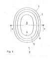
- the ear cups (not shown) included in the hearing protector according to the present invention display an oval outer contour 1.
- the outer contour 1 is also the outer contour of that sealing ring 2 which is secured along the periphery of the ear cups.
- the outer contour of the sealing ring is largely oval, but its detailed configuration may vary considerably from a substantially more circular shape to a considerably more flattened, elongate oval configuration.
- the sealing ring 2 has further, as is apparent from Fig. 1 , a central region 3 which is defined by an inner contour 4 of the sealing ring 2. It will be apparent from the Figure that the distance between the outer contour 1 and the inner contour 4 is to all essentials the same 'all the way round'.
- the sealing ring 2 comprises a number of circumferential lamellae disposed in a radial direction with interspacing outside one another, namely an inner lamella 5, an intermediate lamella 6 and an outer lamella 7.
- the terms 'inner', 'intermediate' and 'outer' refer to the sequence in which the lamellae occur in direction from the central, inner region 3 of the sealing ring out to its outer contour 1.
- the lamellae are three in number, but there are theoretical grounds that indicate that an increase of the number of lamellae would increase the sound damping capability of the sealing ring.
- problems may be encountered in manufacture by injection moulding. Even if three is the number to be preferred, as few as two may possibly be acceptable, but as large a number as may be handled in terms of production engineering affords further advantages. For practical reasons of production, the highest relevant number would probably lie in the range of between five and eight.
- the base plate 10 of the sealing ring is secured or mounted on a mounting plate 11 which is also annular and substantially planar.
- the mounting plate 11 is manufactured from a configurationally stable material, preferably injection moulded plastic material. Further, the mounting plate 11 displays, along a radial outer edge region, fixing means 12 for sealingly joining together with a corresponding fixing means, disposed along the peripheral region of the ear cup.
- the fixing means 12 is suitably designed as a snap device for accommodation in a corresponding undercut groove on the ear cup.
- the base plate 10 and the three lamellae 5, 6 and 7 are of one piece manufacture from the same material.
- the base plate 10 is then connected, for example by gluing, to the mounting ring or plate 11.
- the mounting ring or plate 11 and the lamellae 5, 6 and 7 are manufactured as a continuous material piece by 'double injection moulding' with two different plastic materials in one injection moulding tool.
- the base plate 10 may be more or less attenuated and possibly even completely dispensed with.
- the lamellae 5, 6 and 7 consist of funnel-shaped formations with their greatest cross-sectional dimension at their edge portions formed for abutment against the wearer's head.
- the lamellae are obliquely directed from the central region of the sealing ring 2 out towards the periphery 1 in a direction away from the acoustic ear cup towards the wearer's head.
- the cross sections are gently arched and that the lamellae have outer edge portions 13, 14 and 15, respectively which are slightly more arched or curved radially outwards than is the case for the remaining portions of the lamellae.
- the outer edge portions 13, 14 and 15 may have a radius of curvature of 5-10 mm, while the remaining portions of the lamellae have a radius of curvature of approximately 25-30 mm.
- These outer edge portions 13, 14 and 15 have slightly less material thickness than the remainder of the lamellae, which could have a thickness of approximately 2-5 mm, and are intended to be bent on contact against the head of the wearer so that band-shaped, relatively broad contact surfaces occur.
- these portions will also be slightly more flexible than is the case for the remainder of the lamellae.
- the ability of the lamellae to form and shape themselves in response to irregularities in the wearer's head is improved.
- the radially innermost lamella 5 in the unloaded state i.e. when the hearing protector is not being worn and, thus, is not pressed against the wearer's head, is of greater extent than the radially extrajacent lamellae 6 and 7, lying radially outside in a direction away from the acoustic ear cup, i.e. from the base plate 10 and upwards in Fig. 2 .
- the height of the unloaded, innermost lamella 5 could be in the range of 15-20 mm, and the outermost lamella 1-3 mm shorter.
- the lamellae 5, 6 and 7 are produced from a resilient, possibly elastic material.
- This material is homogeneous and is thus not a foamed material with inner pores or the like.
- the defining surfaces of the lamellae, which also applies to the defining surfaces of the base plate 10 are smooth and substantially pore-free.
- Such a design of the defining surfaces entails that the sealing ring may readily be cleaned by washing.
- a material which, regarding cleaning possibilities, is equivalent to a pore-free solid material is the so-called integral foam, i.e. a foamed material which has a dense surface skin without pores.
Landscapes
- Health & Medical Sciences (AREA)
- Life Sciences & Earth Sciences (AREA)
- Biomedical Technology (AREA)
- Animal Behavior & Ethology (AREA)
- Biophysics (AREA)
- Otolaryngology (AREA)
- Psychology (AREA)
- Engineering & Computer Science (AREA)
- Physics & Mathematics (AREA)
- Heart & Thoracic Surgery (AREA)
- Vascular Medicine (AREA)
- Acoustics & Sound (AREA)
- General Health & Medical Sciences (AREA)
- Public Health (AREA)
- Veterinary Medicine (AREA)
- Orthopedics, Nursing, And Contraception (AREA)
- Helmets And Other Head Coverings (AREA)
- Headphones And Earphones (AREA)
- Respiratory Apparatuses And Protective Means (AREA)
Abstract
Description
- The present invention relates to a hearing protector comprising two ear cups which are designed to cover the ears of the wearer of the hearing protector, and sealing rings which are secured along the peripheries of the ear cups, the sealing rings each displaying at least one circumferential lamella being manufactured from a resilient, possibly elastic material, and being formed to sealingly abut, around the wearer's ears, against the wearer's head.
- Hearing protectors of the type which have two ear cups which are intended to enclose and seal about the ears of a wearer are previously known in a plurality of different variations. In order to ensure the sealing between the ear cup and the head of the wearer, the ear cup has, along its periphery, a sealing ring which is formable, possibly elastic, and which establishes a sealing abutment against the wearer's head, surrounding the wearer's ears. Normally, the sealing ring is manufactured from a foamed material, which is housed in a foil-like casing, which is that part of the sealing ring abutting against the head of the wearer.
- By an adaptation of the properties of the foamed material, optimation of the sealing ring may be made, both as regards sound damping, sealing and the feeling of more or less comfort in wearing the hearing protector. Thus, it has proved that a more rigid and hard sealing ring increases the sound damping properties of the hearing protector, but reduces the level of comfort for the wearer of the hearing protector. In addition, an excessively hard sealing ring can also jeopardise the sealing action between the sealing ring and the wearer's head, since an overly hard sealing ring is incapable of forming itself in adaptation to the head of the wearer to a sufficient degree.
- As regards the perceived comfort when wearing a hearing protector, the ambient temperature is a major factor, since perspiration often occurs both interiorly in the hearing protector and between the sealing ring of the hearing protector and the skin or the wearer. Hence, excessive perspiration is perceived as unpleasant.
- Another aspect concerning perspiration is that the hearing protector becomes dirty, and so should be cleaned at regular intervals, which is difficult or even impossible when foamed material is used in the sealing ring.
- A further aspect in storage or use of hearing protectors at high ambient temperatures, for example if a hearing protector is left in a motor car or an aeroplane out in the sunlight, is that the high temperatures that prevail can considerably affect the material properties in the foamed material which is normally used in the sealing rings. A hearing protector heated in this manner can have completely different properties than those which were originally intended.
- Other problems may occur in severe cold, where many foamed materials show a tendency to become excessively hard.
- Hearing protectors are previously known in the art which display sealing rings of another type than the type under consideration here. Thus, USPS 5,920,911 discloses a hearing protector where the above-considered sealing ring consisting of a foamed material has been replaced by a sealing ring that comprises a number of circumferential lamellae (designated lips) disposed in a radial direction with interspacing outside one another. These lamellae are produced from a resilient, possibly elastic material and have edge surfaces which are intended, under deformation, to sealingly abut against the wearer's head around the wearer's ear. These lamellae have attenuated edge portions facing towards the wearer's head, these portions constituting the actual contact surfaces against the wearer's skin. Such contact surfaces afford more or less only straight line contact against the skin, for which reason the abutment pressure may be considerable, with great risk that the hearing protector is perceived as uncomfortable already after only a short period of use.
- In certain embodiments, there are disposed between the lamellae porous damping bodies produced from fibrous or foamed material, which would render an efficient cleaning of a hearing protector formed in this manner more or less impossible.
- The present invention has for its object to design the hearing protector intimated by way of introduction such that the drawbacks inherent in the prior art technology are obviated. In particular, the present invention has for its object to realise a hearing protector where the sealing ring offers a high degree of comfort, combined with effective sealing and good sound damping. Further, the present invention has for its object to design the hearing protector according to the present invention such that a choice of materials is possible, which entails resistance also to greatly elevated temperatures. Finally, the present invention has for its object to realise a hearing protector where the sealing ring may be produced in a simple and economical manner and where it may simply be kept clean.
- The objects forming the basis of the present invention will be attained if the hearing protector intimated by way of introduction is characterised in that the lamella, at least along its edge regions located most proximal the wearer's head, display portions which, in a direction towards the wearer, are arched from a central region in the sealing ring out towards its periphery.
- The present invention will now be described in greater detail hereinbelow, with reference to the accompanying Drawings. In the accompanying Drawings:
- Fig. 1
- is a plan view of an ear cup included in a hearing protector according to the present invention, seen from that direction which is turned to face towards the head of the wearer;
- Fig. 2
- is a section taken along the section line A-A in
Fig. 1 , only the sealing ring in the ear cup being shown; and - Fig. 3
- is a perspective view of the sealing ring included in the hearing protector according to
Fig. 1 . - It will be apparent from
Fig. 1 that the ear cups (not shown) included in the hearing protector according to the present invention display an ovalouter contour 1. In actual fact, theouter contour 1 is also the outer contour of thatsealing ring 2 which is secured along the periphery of the ear cups. The outer contour of the sealing ring is largely oval, but its detailed configuration may vary considerably from a substantially more circular shape to a considerably more flattened, elongate oval configuration. Thesealing ring 2 has further, as is apparent fromFig. 1 , acentral region 3 which is defined by aninner contour 4 of thesealing ring 2. It will be apparent from the Figure that the distance between theouter contour 1 and theinner contour 4 is to all essentials the same 'all the way round'. - The
sealing ring 2 comprises a number of circumferential lamellae disposed in a radial direction with interspacing outside one another, namely aninner lamella 5, anintermediate lamella 6 and anouter lamella 7. In this instance, the terms 'inner', 'intermediate' and 'outer' refer to the sequence in which the lamellae occur in direction from the central,inner region 3 of the sealing ring out to itsouter contour 1. - In the embodiment under consideration here, as is apparent from the foregoing, the lamellae are three in number, but there are theoretical grounds that indicate that an increase of the number of lamellae would increase the sound damping capability of the sealing ring. At the same time, problems may be encountered in manufacture by injection moulding. Even if three is the number to be preferred, as few as two may possibly be acceptable, but as large a number as may be handled in terms of production engineering affords further advantages. For practical reasons of production, the highest relevant number would probably lie in the range of between five and eight.
- It will be apparent from
Fig. 2 that, between neighbouring lamellae, there are gap-shaped circumferential spaces, aninner space 8 between theinner lamella 5 and theintermediate lamella 6, and anouter space 9 between theintermediate lamella 6 and theouter lamella 7. Both of thesespaces sealing ring 2. - It will further be apparent from
Fig. 2 that thelamellae annular base plate 10, which is substantially planar and, in the mounted state of the sealing ring on the ear cup, parallel with its free edge. - In the embodiment illustrated in
Fig. 2 , thebase plate 10 of the sealing ring is secured or mounted on amounting plate 11 which is also annular and substantially planar. Themounting plate 11 is manufactured from a configurationally stable material, preferably injection moulded plastic material. Further, themounting plate 11 displays, along a radial outer edge region, fixing means 12 for sealingly joining together with a corresponding fixing means, disposed along the peripheral region of the ear cup. Thefixing means 12 is suitably designed as a snap device for accommodation in a corresponding undercut groove on the ear cup. - In the illustrated embodiment, the
base plate 10 and the threelamellae base plate 10 is then connected, for example by gluing, to the mounting ring orplate 11. - According to the present invention, it however also possible to manufacture the mounting ring or
plate 11 and thelamellae base plate 10 may be more or less attenuated and possibly even completely dispensed with. - It will be apparent from
Figs. 2 and 3 taken together that thelamellae ring 2 out towards theperiphery 1 in a direction away from the acoustic ear cup towards the wearer's head. It will further be apparent fromFig. 2 that the cross sections are gently arched and that the lamellae haveouter edge portions outer edge portions outer edge portions edge portions - As a result of the slightly larger material cross sections and as a result of the direction of the portions of the lamellae located most proximal the
base plate 10, there will be obtained an improved supporting effect from these portions of the lamellae. - It will be apparent from
Fig. 2 that the radiallyinnermost lamella 5 in the unloaded state, i.e. when the hearing protector is not being worn and, thus, is not pressed against the wearer's head, is of greater extent than theradially extrajacent lamellae base plate 10 and upwards inFig. 2 . In non-limiting embodiments, the height of the unloaded,innermost lamella 5 could be in the range of 15-20 mm, and the outermost lamella 1-3 mm shorter. - It will be apparent from the foregoing taken together regarding the
spaces - As was mentioned by way of introduction, the
lamellae base plate 10, are smooth and substantially pore-free. Such a design of the defining surfaces entails that the sealing ring may readily be cleaned by washing. - A material which, regarding cleaning possibilities, is equivalent to a pore-free solid material is the so-called integral foam, i.e. a foamed material which has a dense surface skin without pores.
Claims (13)
- A hearing protector comprising two ear cups which are designed to cover the ears of the wearer of the hearing protector, and sealing rings (2) which are secured along the peripheries of the ear cups, the sealing rings each displaying at least one circumferential lamella (5, 6, 7), being manufactured from a resilient, possibly elastic material, and being formed to sealingly abut, around the wearer's ears, against the wearer's head, wherein the lamella (5,6, 7), at least along its edge regions located most proximal the wearer's head, display portions (13, 14, 15) which, in a direction towards the wearer, are arched from a central region (3) in the sealing ring (2) out towards its periphery (1).
- The hearing protector as claimed in Claim 1 characterised in that more than one lamella (5, 6, 7) are disposed in a radial direction with spacing outside one another on each sealing ring.
- The hearing protector as claimed in Claim 1 or 2 , characterised in that the lamellae (5, 6, 7) constitute funnel-like formations, with their largest cross-sectional dimension at their edge portions (13, 14, 15) formed for abutment against the wearer's head.
- The hearing protector as claimed in any of Claims 2 or 3, characterised in that the lamellae (5, 6, 7) are mutually interconnected to one another by the intermediary of an annular base plate (10) which is located on that side of the sealing ring (2) facing towards the ear cup.
- The hearing protector as claimed in Claim 4, characterised in that the base plate (10) is substantially planar.
- The hearing protector as claimed in any of Claims 4 or 5, characterised in that the base plate (10) is substantially configurationally stable and that, along a radial outer edge region, it is provided with fixing means (12) for sealingly joining together with the peripheral region of a ear cup.
- The hearing protector as claimed in any of Claims 4 or 5, characterised in that the base plate (10) is of one piece manufacture with the lamellae (5, 6, 7) and is secured on a substantially configurationally stable mounting ring (11) which, along a radial outer edge region, has fixing means (12) for sealingly joining together with the peripheral region of a ear cup.
- The hearing protector as claimed in any of Claims 2 to 6, characterised in that, between neighbouring lamellae (5, 6, 7), there are gap-formed, circumferential spaces (8, 9) and that the spaces, in the radial direction, are of different widths.
- The hearing protector as claimed in Claim 8, characterised in that the spaces (8, 9) are of irregular form, with non-parallel defining surfaces.
- The hearing protector as claimed in any of Claims 2 to 9, characterised in that the radially innermost lamella (5) in the unloaded state has greater extent than radially extrajacent lamellae (6, 7) in a direction away from the ear cup.
- The hearing protector as claimed in any of Claims 1 to 10, characterised in that the lamellae (5, 6, 7) are of a material thickness that decreases in a direction away from the ear cup.
- The hearing protector as claimed in any of Claims 1 to 11, characterised in that the lamellae (5, 6, 7) have defining surfaces that are smooth and substantially pore-free.
- The hearing protector as claimed in any of Claims 4 to 12, characterised in that the base plate (10) has defining surfaces that are smooth and substantially pore-free.
Priority Applications (9)
| Application Number | Priority Date | Filing Date | Title |
|---|---|---|---|
| EP09156541A EP2238951A1 (en) | 2009-03-27 | 2009-03-27 | Hearing protector |
| US13/203,253 US8302731B2 (en) | 2009-03-27 | 2010-03-05 | Hearing protector |
| CN201080012001.8A CN102348434B (en) | 2009-03-27 | 2010-03-05 | Hearing protectors |
| CA2756454A CA2756454A1 (en) | 2009-03-27 | 2010-03-05 | Hearing protector |
| AU2010229187A AU2010229187B2 (en) | 2009-03-27 | 2010-03-05 | Hearing protector |
| BRPI1006399A BRPI1006399A2 (en) | 2009-03-27 | 2010-03-05 | hearing protector |
| EP10708071A EP2410961A1 (en) | 2009-03-27 | 2010-03-05 | Hearing protector |
| PCT/US2010/026348 WO2010111013A1 (en) | 2009-03-27 | 2010-03-05 | Hearing protector |
| TW099108223A TW201043203A (en) | 2009-03-27 | 2010-03-19 | Hearing protector |
Applications Claiming Priority (1)
| Application Number | Priority Date | Filing Date | Title |
|---|---|---|---|
| EP09156541A EP2238951A1 (en) | 2009-03-27 | 2009-03-27 | Hearing protector |
Publications (1)
| Publication Number | Publication Date |
|---|---|
| EP2238951A1 true EP2238951A1 (en) | 2010-10-13 |
Family
ID=40872487
Family Applications (2)
| Application Number | Title | Priority Date | Filing Date |
|---|---|---|---|
| EP09156541A Withdrawn EP2238951A1 (en) | 2009-03-27 | 2009-03-27 | Hearing protector |
| EP10708071A Withdrawn EP2410961A1 (en) | 2009-03-27 | 2010-03-05 | Hearing protector |
Family Applications After (1)
| Application Number | Title | Priority Date | Filing Date |
|---|---|---|---|
| EP10708071A Withdrawn EP2410961A1 (en) | 2009-03-27 | 2010-03-05 | Hearing protector |
Country Status (8)
| Country | Link |
|---|---|
| US (1) | US8302731B2 (en) |
| EP (2) | EP2238951A1 (en) |
| CN (1) | CN102348434B (en) |
| AU (1) | AU2010229187B2 (en) |
| BR (1) | BRPI1006399A2 (en) |
| CA (1) | CA2756454A1 (en) |
| TW (1) | TW201043203A (en) |
| WO (1) | WO2010111013A1 (en) |
Cited By (1)
| Publication number | Priority date | Publication date | Assignee | Title |
|---|---|---|---|---|
| WO2017167722A1 (en) * | 2016-03-31 | 2017-10-05 | Husqvarna Ab | Smart earmuff and method for improved use of an earmuff |
Families Citing this family (7)
| Publication number | Priority date | Publication date | Assignee | Title |
|---|---|---|---|---|
| MX2017002082A (en) | 2014-08-18 | 2017-07-10 | 3M Innovative Properties Co | Respirator including polymeric netting and method of forming same. |
| US11185447B2 (en) | 2015-02-19 | 2021-11-30 | Neatcap, Llc | Medical headgear |
| US11806214B2 (en) | 2015-02-19 | 2023-11-07 | Neatcap, Llc | Medical headgear |
| US10413696B2 (en) * | 2015-02-19 | 2019-09-17 | Neatcap, Llc | Medical headgear |
| WO2018150351A1 (en) | 2017-02-16 | 2018-08-23 | 3M Innovative Properties Company | Earmuff hearing-protection device comprising sound-attenuating members |
| CN111372544B (en) | 2017-11-21 | 2023-05-16 | 3M创新有限公司 | Pad for a hearing protector or an audio headset |
| EP3494940A1 (en) * | 2017-12-08 | 2019-06-12 | 3M Innovative Properties Company | A hearing protector having a unidirectional sound inlet |
Citations (3)
| Publication number | Priority date | Publication date | Assignee | Title |
|---|---|---|---|---|
| DE1512666A1 (en) * | 1966-06-01 | 1969-06-12 | Akg Akustische Kino Geraete | Headphone |
| US3506980A (en) * | 1968-12-26 | 1970-04-21 | Gentex Corp | Seal for earcup or the like |
| US5920911A (en) * | 1997-11-17 | 1999-07-13 | Poiesis Research, Inc. | Earcup soft-seal with thinned lips and interleaving layers of damping materials |
Family Cites Families (7)
| Publication number | Priority date | Publication date | Assignee | Title |
|---|---|---|---|---|
| US3944018A (en) * | 1974-08-01 | 1976-03-16 | Rodney Jene Satory | Acoustical seal |
| AT377664B (en) * | 1983-05-26 | 1985-04-25 | Akg Akustische Kino Geraete | EAR CUSHION |
| US4958697A (en) * | 1989-09-11 | 1990-09-25 | The United States Of America As Represented By The Secretary Of The Army | Anatomically shaped earseals for headsets |
| GB9805619D0 (en) * | 1998-03-18 | 1998-05-13 | Noise Cancellation Tech | Cushioned earphones |
| US6820717B2 (en) * | 2003-01-16 | 2004-11-23 | Howard Leight Industries, Llc | Pressure regulating earplug |
| US7305992B2 (en) * | 2003-02-25 | 2007-12-11 | Howard Leight Industries, Llc | Conforming earplug |
| WO2008070662A2 (en) * | 2006-12-04 | 2008-06-12 | Adaptive Technologies, Inc. | Sound-attenuating earmuff having isolated double-shell structure |
-
2009
- 2009-03-27 EP EP09156541A patent/EP2238951A1/en not_active Withdrawn
-
2010
- 2010-03-05 US US13/203,253 patent/US8302731B2/en active Active
- 2010-03-05 BR BRPI1006399A patent/BRPI1006399A2/en not_active Application Discontinuation
- 2010-03-05 EP EP10708071A patent/EP2410961A1/en not_active Withdrawn
- 2010-03-05 AU AU2010229187A patent/AU2010229187B2/en not_active Ceased
- 2010-03-05 WO PCT/US2010/026348 patent/WO2010111013A1/en not_active Ceased
- 2010-03-05 CA CA2756454A patent/CA2756454A1/en not_active Abandoned
- 2010-03-05 CN CN201080012001.8A patent/CN102348434B/en active Active
- 2010-03-19 TW TW099108223A patent/TW201043203A/en unknown
Patent Citations (3)
| Publication number | Priority date | Publication date | Assignee | Title |
|---|---|---|---|---|
| DE1512666A1 (en) * | 1966-06-01 | 1969-06-12 | Akg Akustische Kino Geraete | Headphone |
| US3506980A (en) * | 1968-12-26 | 1970-04-21 | Gentex Corp | Seal for earcup or the like |
| US5920911A (en) * | 1997-11-17 | 1999-07-13 | Poiesis Research, Inc. | Earcup soft-seal with thinned lips and interleaving layers of damping materials |
Cited By (2)
| Publication number | Priority date | Publication date | Assignee | Title |
|---|---|---|---|---|
| WO2017167722A1 (en) * | 2016-03-31 | 2017-10-05 | Husqvarna Ab | Smart earmuff and method for improved use of an earmuff |
| US11633303B2 (en) | 2016-03-31 | 2023-04-25 | Husqvarna Ab | Smart earmuff and method for improved use of an earmuff |
Also Published As
| Publication number | Publication date |
|---|---|
| CA2756454A1 (en) | 2010-09-30 |
| BRPI1006399A2 (en) | 2016-02-10 |
| US20120012418A1 (en) | 2012-01-19 |
| TW201043203A (en) | 2010-12-16 |
| AU2010229187A1 (en) | 2011-09-29 |
| CN102348434A (en) | 2012-02-08 |
| AU2010229187B2 (en) | 2012-12-20 |
| US8302731B2 (en) | 2012-11-06 |
| WO2010111013A1 (en) | 2010-09-30 |
| CN102348434B (en) | 2016-08-24 |
| EP2410961A1 (en) | 2012-02-01 |
Similar Documents
| Publication | Publication Date | Title |
|---|---|---|
| US8302731B2 (en) | Hearing protector | |
| EP3582730B1 (en) | Earmuff hearing-protection device comprising sound-attenuating members | |
| JP6700541B2 (en) | Clothing and bras | |
| EP1467689B1 (en) | Hearing protection device | |
| EP2547300B1 (en) | Hearing protective device with moisture resistant earmuff sound absorbers | |
| AU2003239883A1 (en) | Hearing protection device | |
| CN103686511A (en) | Ear appliance | |
| AU2013201505A1 (en) | Bendable Fastening Assembly and Cushion Formed with the Same | |
| CN101370452B (en) | Ear cup | |
| CA1251301A (en) | Hat | |
| US20180092421A1 (en) | Mechanical-waves Attenuating Protective Headgear | |
| US20040168245A1 (en) | Washable, protective hip pad construction | |
| AU2015401745B2 (en) | A method for manufacturing a sealing ring, and a sealing ring | |
| CN109349719B (en) | Protective cap suitable for being worn by skull wounded person | |
| KR200475355Y1 (en) | Bra cups heartwood | |
| KR101063552B1 (en) | Silicone Rubber Pad Bra with Air Pumping Member | |
| AU2006245537B2 (en) | Improved bunion cushion | |
| JP3080034U (en) | Occipital headgear | |
| JP2002253725A (en) | Head gear for back of head | |
| WO2014120279A1 (en) | Ear sock systems | |
| SE0950963A1 (en) | Nipple protection device | |
| WO2017069671A1 (en) | A hearing protection device and a method for manufacturing said hearing protection device | |
| GB2498974A (en) | Ostomy pouch mounting with variable flexibility |
Legal Events
| Date | Code | Title | Description |
|---|---|---|---|
| PUAI | Public reference made under article 153(3) epc to a published international application that has entered the european phase |
Free format text: ORIGINAL CODE: 0009012 |
|
| AK | Designated contracting states |
Kind code of ref document: A1 Designated state(s): AT BE BG CH CY CZ DE DK EE ES FI FR GB GR HR HU IE IS IT LI LT LU LV MC MK MT NL NO PL PT RO SE SI SK TR |
|
| AX | Request for extension of the european patent |
Extension state: AL BA RS |
|
| RIN1 | Information on inventor provided before grant (corrected) |
Inventor name: NORDIN, HENRIK Inventor name: NILSSON, SIGVARD |
|
| AKY | No designation fees paid | ||
| REG | Reference to a national code |
Ref country code: DE Ref legal event code: R108 Effective date: 20110607 |
|
| STAA | Information on the status of an ep patent application or granted ep patent |
Free format text: STATUS: THE APPLICATION IS DEEMED TO BE WITHDRAWN |
|
| 18D | Application deemed to be withdrawn |
Effective date: 20110414 |