EP2034278A2 - Method and device for determining the flow rate of flowing water - Google Patents
Method and device for determining the flow rate of flowing water Download PDFInfo
- Publication number
- EP2034278A2 EP2034278A2 EP08013142A EP08013142A EP2034278A2 EP 2034278 A2 EP2034278 A2 EP 2034278A2 EP 08013142 A EP08013142 A EP 08013142A EP 08013142 A EP08013142 A EP 08013142A EP 2034278 A2 EP2034278 A2 EP 2034278A2
- Authority
- EP
- European Patent Office
- Prior art keywords
- camera
- liquid
- area
- objects
- determined
- Prior art date
- Legal status (The legal status is an assumption and is not a legal conclusion. Google has not performed a legal analysis and makes no representation as to the accuracy of the status listed.)
- Granted
Links
- 238000000034 method Methods 0.000 title claims abstract description 40
- XLYOFNOQVPJJNP-UHFFFAOYSA-N water Substances O XLYOFNOQVPJJNP-UHFFFAOYSA-N 0.000 title abstract description 20
- 239000007788 liquid Substances 0.000 claims abstract description 80
- 238000009826 distribution Methods 0.000 claims abstract description 8
- 238000005259 measurement Methods 0.000 claims description 14
- 238000001514 detection method Methods 0.000 claims description 6
- 230000005540 biological transmission Effects 0.000 claims description 4
- 230000001419 dependent effect Effects 0.000 claims description 4
- 230000003287 optical effect Effects 0.000 claims description 4
- 238000011156 evaluation Methods 0.000 claims description 3
- 230000002123 temporal effect Effects 0.000 claims description 3
- 238000012935 Averaging Methods 0.000 claims description 2
- 238000002789 length control Methods 0.000 claims description 2
- 230000003797 telogen phase Effects 0.000 claims description 2
- 238000011144 upstream manufacturing Methods 0.000 claims description 2
- 239000003643 water by type Substances 0.000 claims description 2
- 235000013336 milk Nutrition 0.000 abstract description 2
- 239000008267 milk Substances 0.000 abstract description 2
- 210000004080 milk Anatomy 0.000 abstract description 2
- 239000000428 dust Substances 0.000 description 4
- 230000036961 partial effect Effects 0.000 description 4
- 230000002829 reductive effect Effects 0.000 description 4
- 235000013305 food Nutrition 0.000 description 2
- 230000000284 resting effect Effects 0.000 description 2
- 239000000126 substance Substances 0.000 description 2
- 230000036962 time dependent Effects 0.000 description 2
- 101100117236 Drosophila melanogaster speck gene Proteins 0.000 description 1
- 229920006328 Styrofoam Polymers 0.000 description 1
- 238000001816 cooling Methods 0.000 description 1
- 230000003247 decreasing effect Effects 0.000 description 1
- 238000011161 development Methods 0.000 description 1
- 238000005265 energy consumption Methods 0.000 description 1
- 235000011389 fruit/vegetable juice Nutrition 0.000 description 1
- 239000003502 gasoline Substances 0.000 description 1
- 238000009434 installation Methods 0.000 description 1
- 239000003350 kerosene Substances 0.000 description 1
- 230000002045 lasting effect Effects 0.000 description 1
- 238000000691 measurement method Methods 0.000 description 1
- 238000012544 monitoring process Methods 0.000 description 1
- 235000019198 oils Nutrition 0.000 description 1
- 239000002245 particle Substances 0.000 description 1
- 239000003208 petroleum Substances 0.000 description 1
- 230000002035 prolonged effect Effects 0.000 description 1
- 239000002994 raw material Substances 0.000 description 1
- 150000003839 salts Chemical class 0.000 description 1
- 239000000523 sample Substances 0.000 description 1
- 238000004904 shortening Methods 0.000 description 1
- 239000008261 styrofoam Substances 0.000 description 1
- 230000003746 surface roughness Effects 0.000 description 1
- 239000002699 waste material Substances 0.000 description 1
Images
Classifications
-
- G—PHYSICS
- G01—MEASURING; TESTING
- G01F—MEASURING VOLUME, VOLUME FLOW, MASS FLOW OR LIQUID LEVEL; METERING BY VOLUME
- G01F1/00—Measuring the volume flow or mass flow of fluid or fluent solid material wherein the fluid passes through a meter in a continuous flow
- G01F1/002—Measuring the volume flow or mass flow of fluid or fluent solid material wherein the fluid passes through a meter in a continuous flow wherein the flow is in an open channel
-
- G—PHYSICS
- G01—MEASURING; TESTING
- G01F—MEASURING VOLUME, VOLUME FLOW, MASS FLOW OR LIQUID LEVEL; METERING BY VOLUME
- G01F1/00—Measuring the volume flow or mass flow of fluid or fluent solid material wherein the fluid passes through a meter in a continuous flow
- G01F1/704—Measuring the volume flow or mass flow of fluid or fluent solid material wherein the fluid passes through a meter in a continuous flow using marked regions or existing inhomogeneities within the fluid stream, e.g. statistically occurring variations in a fluid parameter
- G01F1/708—Measuring the time taken to traverse a fixed distance
- G01F1/7086—Measuring the time taken to traverse a fixed distance using optical detecting arrangements
-
- G—PHYSICS
- G01—MEASURING; TESTING
- G01P—MEASURING LINEAR OR ANGULAR SPEED, ACCELERATION, DECELERATION, OR SHOCK; INDICATING PRESENCE, ABSENCE, OR DIRECTION, OF MOVEMENT
- G01P5/00—Measuring speed of fluids, e.g. of air stream; Measuring speed of bodies relative to fluids, e.g. of ship, of aircraft
- G01P5/18—Measuring speed of fluids, e.g. of air stream; Measuring speed of bodies relative to fluids, e.g. of ship, of aircraft by measuring the time taken to traverse a fixed distance
Definitions
- the invention relates to a method and a device for determining the surface velocities and the flow rate of liquids in pipelines, open or closed channels and bodies of water.
- the method and apparatus of the invention detects surface velocities and flow rates of liquids of any kind in any type of conduit.
- the invention understands under streams streams, rivers, channels, pipelines, channels and other geometric structures in which liquids are moved.
- the invention means all liquids transported in lines, in particular fresh, salt, brackish, rain, mixed, waste, cooling or process water, food or food raw materials such as milk, oil, juices, chemicals such as petroleum, kerosene or gasoline.
- the method invention solves this problem by optical measurement of the directions and the amounts of the velocity of objects in the area of the liquid surface, measurement of the liquid level, automatic image recognition of the objects and calculation of a temporally and spatially high-resolution object velocity distribution, calculation of a representative surface velocity v 0 of the liquid from the Results of the previous step, determination of a liquid-flow area A from the value of the current liquid level and a stored data set, multiplication of the representative surface velocity v 0 by the area A and a factor k, this factor k being determined from a stored data set, whose values come from a numerical or experimental calibration of the measuring point.
- the automatic image recognition according to the invention is not tuned to known specific objects, but rather can recognize and track unknown objects on or near the liquid surface and calculate their spatial and temporal velocity distribution and the flow rate. If the geometry of the pipe is known, the liquid-level-dependent area A of the partial cross-section through which the liquid flows is determined as a function of the measured liquid level, using data from a stored table containing the area A at different liquid levels or from the data deposited on the area A is interpolated.
- the detection of the objects with a camera takes place, wherein preferably an alignment and focal length control takes place.
- a camera as a sensor expensive special sensors are dispensable.
- the positioning and alignment of the camera and the adjustment of their focal length according to the invention if necessary, manually or computer controlled.
- the computer control serves to be able to vary the liquid cut-off detected with the aid of the camera as a function of the amounts and directions of the detected object speeds.
- the viewing angle range of the camera can also be used in such a way that the surface area of the liquid detected by the camera is divided into partial areas and the speeds of the objects are assigned to these partial areas depending on the position. In this way one obtains highly detailed spatially dependent surface velocity distributions for the entire observed area of the liquid surface.
- the determined data and / or the evaluation results are communicated to measured value users, preferably via the Internet.
- the measured value user (s) can stand at any distance from the measured object, For example, in a control or emergency center of an industrial company, a public institution or the like.
- the use of data transmission via the Internet simplifies the application of the method.
- the computer 4 is arranged either adjacent to the camera at a location remote from it, for example in a signal box or in a control or control center of a computer center, which looks after a whole series of devices according to the invention along the water.
- the computer 4 is equipped with a software for automatic image recognition and for calculating the indicated in the drawing by an arrow 6 object speed.
- an object identified in the vicinity of the surface of the water such as a speck of dust, is assigned a local position (x, y) on the surface of the water, for which the absolute value and the direction of the surface velocity v 0 (x, y) of the body currently prevailing here determined by the two camera images.
- the respective prevailing surface velocities v 0 (x, y) are determined according to the invention for a very large number of individual positions (x, y) of the viewing angle range of the body of water detected with the aid of the camera 3.
- the device is able to reliably determine flow rates by means of the method according to the invention, even at very low, no or negative surface speeds.
- the camera 3 may be mounted on a bridge, for example. In this case, the camera 3 may be oriented vertically downwards or inclined. Not shown is an attachment of the device on a boom, a mast, a pole on the shore or the like.
- the apparatus for saving electrical energy after a determination of surface speeds for a certain time temporarily be put into a resting state.
- the flow velocity of the water usually does not change in the short term. So it is often enough in practice, if every quarter of an hour a measurement sequence is performed. This typically only takes a few seconds, so that a few seconds lasting active phase is followed by a rest period of about 14 to 15 minutes. As a result, the battery life is multiplied, in this example, at least 15 times. Of course, a five or more minute measurement can be followed by a correspondingly reduced or prolonged rest period.
- Such applications could be, for example, pipelines that carry liquid in batches.
Landscapes
- Physics & Mathematics (AREA)
- General Physics & Mathematics (AREA)
- Fluid Mechanics (AREA)
- Engineering & Computer Science (AREA)
- Aviation & Aerospace Engineering (AREA)
- Measuring Volume Flow (AREA)
- Indicating Or Recording The Presence, Absence, Or Direction Of Movement (AREA)
Abstract
Description
Die Erfindung betrifft ein Verfahren und eine Vorrichtung zur Bestimmung der Oberflächengeschwindigkeiten und der Durchflussmenge von Flüssigkeiten in Rohrleitungen, offenen oder geschlossenen Kanälen und Gewässern.The invention relates to a method and a device for determining the surface velocities and the flow rate of liquids in pipelines, open or closed channels and bodies of water.
Das erfindungsgemäße Verfahren und die Vorrichtung ermitteln Oberflächengeschwindigkeiten und Durchflussmengen von Flüssigkeiten jeder Art in jeder Art von Leitungen. Hierbei versteht die Erfindung unter Leitungen Bäche, Flüsse, Kanäle, Rohrleitungen, Gerinne und sonstige geometrische Strukturen, in denen Flüssigkeiten bewegt werden. Unter Flüssigkeiten versteht die Erfindung sämtliche in Leitungen transportierte Flüssigkeiten, insbesondere Süß-, Salz-, Brack-, Regen-, Misch-, Ab-, Kühl- oder Prozesswasser, Lebensmittel oder Lebensmittelrohstoffe wie Milch, Öl, Säfte, Chemikalien wie Erdöl, Kerosin oder Benzin.The method and apparatus of the invention detects surface velocities and flow rates of liquids of any kind in any type of conduit. Here, the invention understands under streams streams, rivers, channels, pipelines, channels and other geometric structures in which liquids are moved. Under liquids, the invention means all liquids transported in lines, in particular fresh, salt, brackish, rain, mixed, waste, cooling or process water, food or food raw materials such as milk, oil, juices, chemicals such as petroleum, kerosene or gasoline.
Ein Verfahren zum Messen des Durchflusses in Rohrleitungen und offenen Gerinnen ist aus der
Aufgabe der Erfindung ist es, ein Verfahren der eingangs genannten Art anzugeben, welches berührungslos arbeitet und dabei besonders genau und wirtschaftlich ausführbar ist und insbesondere bei sehr geringen oder negativen Oberflächengeschwindigkeiten und Durchflussmengen gut anwendbar ist.The object of the invention is to provide a method of the type mentioned, which operates without contact and is particularly accurate and economical to carry out and is well applicable especially at very low or negative surface speeds and flow rates.
Die Verfahrenserfindung löst diese Aufgabe über optische Messung der Richtungen und der Beträge der Geschwindigkeiten von Objekten im Bereich der Flüssigkeitsoberfläche, Messung des Flüssigkeitsstandes, automatische Bilderkennung der Objekte und Berechnung einer zeitlich und räumlich hoch aufgelösten Objektgeschwindigkeitsverteilung, Berechnung einer repräsentativen Oberflächengeschwindigkeit v0 der Flüssigkeit aus den Ergebnissen des vorherigen Schrittes, Ermittlung einer von der Flüssigkeit durchströmten Fläche A aus dem Wert des aktuellen Flüssigkeitsstandes und einem hinterlegten Datensatz, Multiplikation der repräsentativen Oberflächengeschwindigkeit v0 mit der Fläche A und einem Faktor k, wobei dieser Faktor k aus einem hinterlegten Datensatz ermittelt wird, dessen Werte aus einer numerischen oder experimentellen Kalibration der Messstelle stammen. Im Gegensatz zu anderen bekannten Verfahren, wie beispielsweise hydrometrischen Messflügeln oder Ultraschallanlagen, arbeitet das erfindungsgemäße Verfahren mit großem Vorteil berührungslos und aus sicherer Entfernung von der Flüssigkeitsoberfläche, so dass das Ausfallrisiko deutlich vermindert ist. Die für die Durchführung des Verfahrens erforderlichen Vorrichtungen können daher weder durch die Strömung noch durch Inhaltsstoffe oder die chemische Natur der Flüssigkeit noch durch mitgeführte Objekte wie beispielsweise Eis oder Treibgut, beschädigt oder zerstört werden.The method invention solves this problem by optical measurement of the directions and the amounts of the velocity of objects in the area of the liquid surface, measurement of the liquid level, automatic image recognition of the objects and calculation of a temporally and spatially high-resolution object velocity distribution, calculation of a representative surface velocity v 0 of the liquid from the Results of the previous step, determination of a liquid-flow area A from the value of the current liquid level and a stored data set, multiplication of the representative surface velocity v 0 by the area A and a factor k, this factor k being determined from a stored data set, whose values come from a numerical or experimental calibration of the measuring point. In contrast to other known methods, such as, for example, hydrometric measuring wings or ultrasonic systems, the method according to the invention works with great advantage without contact and from a safe distance from the liquid surface, so that the risk of failure is markedly reduced. The devices required for carrying out the method can therefore neither be damaged by the flow, nor by the contents or the chemical nature of the liquid nor by entrained objects such as ice or flotsam.
Im Gegensatz zu bekannten Radar-Geschwindigkeitsmessungen ist das erfindungsgemäße optische Verfahren sowohl unempfindlich gegen Wellen als auch gegenüber der Oberflächengeschwindigkeit/Durchflussmenge selber. Mit großem Vorteil ist das erfindungsgemäße optische Verfahren für alle praxisrelevanten Geschwindigkeiten geeignet, also gleichermaßen für sehr schnelle und sehr langsame, stehende oder sogar rückwärts fließende Flüssigkeiten, so dass sämtliche Durchflusszustände sicher erfasst werden. Eine radarbasierte Messung hat gerade bei langsamfließenden oder gar stehenden Flüssigkeiten große Probleme, da die Flüssigkeitsoberfläche mit abnehmender Geschwindigkeit zunehmend glatter wird, so dass die Rückstreuung der Signale stark reduziert ist. Hierdurch werden die Radarsignale immer schwächer, bis sie schließlich im stets vorhandenen Rauschen untergehen und nicht mehr zweifelsfrei detektierbar sind. Durch die Verwendung von Objekten im Bereich der Flüssigkeitsoberfläche als Marker für die Oberflächengeschwindigkeit ist das Verfahren mit großem Vorteil unabhängig von Oberflächenrauhigkeiten oder dergleichen. Die automatische Bilderkennung ist erfindungsgemäß nicht auf bekannte spezifische Objekte abgestimmt, sondern kann vielmehr unbekannte Objekte auf oder nahe der Flüssigkeitsoberfläche erkennen und verfolgen und deren räumliche und zeitliche Geschwindigkeitsverteilung und die Durchflussmenge berechnen. Bei bekannter Geometrie der Leitung wird die flüssigkeitsstandsabhängige Fläche A des von der Flüssigkeit durchflossenen Teilquerschnitts in Abhängigkeit vom gemessenen Flüssigkeitsstand bestimmt, wobei auf Daten einer hinterlegten Tabelle zurückgegriffen wird, die die Fläche A bei unterschiedlichen Flüssigkeitsständen enthält oder aus der mittels der hinterlegten Daten auf die Fläche A interpoliert wird. Der gesuchte Durchfluß Q ergibt sich gemäß Q = A·vm durch Multiplikation dieser Fläche A mit der mittleren Fließgeschwindigkeit vm des durchflossenen Teilquerschnitts, die aus der repräsentativen Oberflächengeschwindigkeit v0 gemäß vm = k·v0 berechnet wird. Dabei bezeichnet k das dimensionslose Geschwindigkeitsverhältnis von vm zu v0 zwischen dem Querschnittsmittel vm der Geschwindigkeit und der erfindungsgemäß bestimmten repräsentativen Oberflächengeschwindigkeit v0. Der Faktor k ist leitungsprofil-, flüssigkeitsstands- und teilweise auch geschwindigkeitsabhängig und wird durch Kalibrierung der Durchflussmessstelle bestimmt. Eventuell nicht im hinterlegten Datensatz vorhandene Werte von k zu bestimmten Flüssigkeitsständen werden mittels Interpolation aus den vorhandenen Werten ermittelt. Die Kalibrierung kann alternativ durch Messung oder durch numerische Berechnung erfolgen. Bei der messtechnischen Kalibrierung werden die repräsentativen Oberflächengeschwindigkeiten v0 erfindungsgemäß und die Durchflüsse Q mit Hilfe eines unabhängigen Messverfahrens zeitgleich gemessen. Aus diesen zeitgleichen Messungen resultieren die dimensionslosen Geschwindigkeitsverhältnisse gemäß k= vm/v0 = (Q/A)/v0. Zu Vergleichs- und Kalibrationszwecken können die Durchflüsse beispielsweise mittels hydrometrischer oder magnetischinduktiver Messflügel, mittels Wehranlagen oder anderer bekannter Durchflussmessverfahren gemessen werden. Numerische Messstellenkalibrierung ist bekannt und in der
In Ausgestaltung der Erfindung ist vorgesehen, dass die Objekte natürlichen oder künstlichen Ursprungs sind. Als natürliche Objekte kommen insbesondere Blütenstaub, Treibgut, Luftblasen oder dergleichen in Betracht. Es ist nicht erforderlich, der Flüssigkeit künstliche Objekte wie Styroporkugeln oder künstlich erzeugte Luftblasen zuzufügen. Die Erzeugung eines Luftblasenvorhangs aus einem leitungsquerenden Druckluftrohr ist schon allein wegen der Installation des Druckluftrohres teuer und die Erzeugung des notwendigen Luftdrucks energieaufwendig. Falls gewünscht, können derartige künstliche Partikel erfindungsgemäß natürlich ebenfalls verwendet werden, da die automatische Bilderkennung selbstverständlich auch diese erkennen und verfolgen kann. Welche Art von Objekten, egal ob natürlich in oder auf der Flüssigkeit vorhanden oder künstlich zugefügt, verwendet werden, betrifft nicht den Kern der Erfindung. Besonders vorteilhaft ist natürlich die Verwendung bereits in der Flüssigkeit vorhandener Objekte wie Blätter, Treibgut, etc.In an embodiment of the invention, it is provided that the objects are of natural or artificial origin. Particularly suitable natural objects are pollen, flotsam, air bubbles or the like. It is not necessary to add artificial objects such as styrofoam balls or artificially created air bubbles to the liquid. The creation of a bubble curtain from a line-crossing compressed air pipe is already alone because of the installation of the compressed air pipe expensive and the generation of the necessary air pressure energy consuming. Of course, if desired, such artificial particles can also be used according to the invention, since of course the automatic image recognition can also recognize and track them. What type of objects, whether naturally present in or on the liquid or artificially added, are not at the heart of the invention. Of course, particularly advantageous is the use of already existing in the liquid objects such as leaves, flotsam, etc.
In Ausgestaltung der Erfindung ist vorgesehen, dass die Erfassung der Objekte mit einer Kamera, vorzugsweise einer CCD- oder einer digitalen Kamera, insbesondere einer mit Objektiven versehenen Kamera, erfolgt, wobei vorzugsweise eine Ausrichtungs- und Brennweitensteuerung erfolgt. Durch die Verwendung einer Kamera als Sensor werden teure Spezialsensoren entbehrlich. Die Positionierung und Ausrichtung der Kamera und die Einstellung ihrer Brennweite erfolgt erfindungsgemäß bedarfsweise manuell oder computergesteuert. Die Computersteuerung dient dazu, den mit Hilfe der Kamera erfassten Flüssigkeitsausschnitt in Abhängigkeit von den Beträgen und Richtungen der erfassten Objektgeschwindigkeiten variieren zu können.In an embodiment of the invention it is provided that the detection of the objects with a camera, preferably a CCD or a digital camera, in particular a camera provided with lenses, takes place, wherein preferably an alignment and focal length control takes place. By using a camera as a sensor expensive special sensors are dispensable. The positioning and alignment of the camera and the adjustment of their focal length according to the invention, if necessary, manually or computer controlled. The computer control serves to be able to vary the liquid cut-off detected with the aid of the camera as a function of the amounts and directions of the detected object speeds.
In Ausgestaltung der Erfindung ist daher vorgesehen, dass in einer Sequenz von Bildern der Kamera in wenigstens zwei, vorzugsweise mehr als zwei Bildern, mindestens ein, vorzugsweise mehrere, Objekte identifiziert und ihre Wege durch den von der Kamera erfassten Blickwinkelbereich als Funktion der Zeit verfolgt und daraus die Objektgeschwindigkeiten berechnet werden. Durch die erfindungsgemäße Identifizierung desselben Objektes in verschiedenen Bildern werden der Weg und aufgrund der bekannten Zeitpunkte der aufeinanderfolgenden Aufnahmen auch die zeitabhängigen Absolutbeträge und Richtungen der Objektgeschwindigkeiten bestimmt. Bei geringer Objektgröße entsprechen diese zeitabhängigen Absolutbeträge und Richtungen der Geschwindigkeit des identifizierten Objekts den entlang des erfassten Objektwegs vorherrschenden Mittelwerten der Absolutbeträge und Richtungen der Oberflächengeschwindigkeit der Flüssigkeit. Erfindungsgemäß werden daher nur hinreichend kleine Objekte identifiziert, wobei deren Auswahlgröße relativ zur Leitungsgröße ist. Die identifizierten Objekte werden erfindungsgemäß jeweils in einem ersten Referenzbild an einer ersten Position A und in einem um Δt später aufgenommenen Vergleichsbild an einer zweiten Position B detektiert. Aus dem Weg zwischen A und B und der dafür benötigen Zeitspanne Δt werden Betrag und Richtung der lokalen Oberflächengeschwindigkeit v0 berechnet und der lokalen Position M der Flüssigkeitsoberfläche zugeordnet, wobei sich M in der Nähe von A und B befindet, beispielsweise das Mittel der identifizierten Positionen A und B ist. Anstelle der Mittelposition kann erfindungsgemäß auch eine andere Wichtung vorgenommen werden, beispielsweise eine Drittel- oder Zehntelposition. Es ist von besonderem Vorteil, wenn mehrere Objekte zur Geschwindigkeitsbestimmung ausgewertet werden. Da die Kamera in der Regel stets viele Objekte im Blickfeld hat, kann die vielfältige Information einfach durch größeren Rechenaufwand des Computers ermittelt werden. Die vielen Einzelwerte der Objektgeschwindigkeiten erlauben eine sehr viel genauere Bestimmung der mittleren Oberflächengeschwindigkeit. Darüber hinaus ermöglicht hierdurch das Verfahren zu ermitteln, welche Oberflächengeschwindigkeit wo gemessen wird, so dass die Oberflächengeschwindigkeit nicht nur punktuell sondern in ihrer räumlichen Verteilung ermittelt wird.In an embodiment of the invention it is therefore provided that in a sequence of images of the camera in at least two, preferably more than two images, at least one, preferably more, identified objects and their paths through the detected by the camera viewing angle range as a function of time and from this, the object speeds are calculated. The inventive identification of the same object in different images determines the path and, because of the known points in time of the successive shots, the time-dependent absolute values and directions of the object speeds. Correspond to a small object size these time-dependent absolute values and directions of the velocity of the identified object are the mean values of the absolute values and directions of the surface velocity of the liquid prevailing along the detected object path. According to the invention, therefore, only sufficiently small objects are identified, with their selection variable being relative to the line size. According to the invention, the identified objects are respectively detected in a first reference image at a first position A and in a comparison image later acquired by Δt at a second position B. From the distance between A and B and the time span Δt required therefor, the magnitude and direction of the local surface velocity v 0 are calculated and assigned to the local position M of the liquid surface, where M is in the vicinity of A and B, for example the mean of the identified positions A and B is. Instead of the center position can be made according to the invention, a different weighting, for example, a third or tenth position. It is of particular advantage if several objects are evaluated for speed determination. Since the camera usually always has many objects in view, the diverse information can be easily determined by greater computational complexity of the computer. The many individual values of the object speeds allow a much more accurate determination of the average surface speed. In addition, this allows the method to determine which surface velocity is measured where, so that the surface velocity is determined not only punctually but in their spatial distribution.
Beispielsweise kann die Genauigkeit dadurch erhöht werden, dass der zu berechnende Wert für die Oberflächengeschwindigkeit durch Mittelwertbildung gegebenenfalls ohne Berücksichtigung besonders untypischer Einzelwerte ermittelt wird. In einem Cluster von Einzelwerten sind besonders untypische Einzelwerte daran zu erkennen, dass sie sehr stark vom Durchschnitt abweichen. In einem solchen Fall liegt die Vermutung einer Fehlmessung nahe, so dass durch außer Acht lassen solcher untypischer Einzelwerte in der Regel der aus den verbleibenden Einzelwerten gebildete Mittelwert genauer ausfällt.For example, the accuracy can be increased by determining the value for the surface velocity to be calculated by averaging, if appropriate, without consideration of particularly atypical individual values. In a cluster of individual values especially untypical individual values can be recognized by the fact that they deviate very much from the average. In such a case, the assumption of an erroneous measurement is close, so that disregarding such untypical individual values usually the average value formed from the remaining individual values is more accurate.
Der Blickwinkelbereich der Kamera kann darüber hinaus auch so genutzt werden, dass der von der Kamera erfasste Oberflächenbereich der Flüssigkeit in Teilbereiche aufgeteilt und die Geschwindigkeiten der Objekte jeweils positionsabhängig diesen Teilbereichen zugeordnet werden. Auf diese Weise erhält man sehr detaillierte ortsabhängige Verteilungen der Oberflächengeschwindigkeit für den gesamten beobachteten Bereich der Flüssigkeitsoberfläche.The viewing angle range of the camera can also be used in such a way that the surface area of the liquid detected by the camera is divided into partial areas and the speeds of the objects are assigned to these partial areas depending on the position. In this way one obtains highly detailed spatially dependent surface velocity distributions for the entire observed area of the liquid surface.
Der von der Kamera erfasste Bereich der Flüssigkeitsoberfläche kann je nach Kameraabstand, Blickwinkel und Brennweite die Größenordnungen von etwa 0,1 m bis etwa 100 m überspannen. Ein kleiner Kameraausschnitt erfordert bei schnell fließender Flüssigkeit schnellere Messvorgänge als ein großer Kameraausschnitt bei einer langsam fließenden Flüssigkeit. Aus diesem Grund sieht die Weiterbildung der Erfindung vor, dass in Abhängigkeit des von der Kamera erfassten Bereichs der Flüssigkeitsoberfläche und der ermittelten Oberflächengeschwindigkeiten der zeitliche Abstand zwischen der Erfassung zweier Bilder variierbar ist, vorzugsweise zwischen 0,001 Sekunden und 900 Sekunden, insbesondere zwischen 0,01 Sekunden und 60 Sekunden. Auf diese Weise können die zur Verfügung stehenden Ressourcen der Kamera und des Computers je nach Anforderung optimal genutzt werden. Erfindungsgemäß ist dabei vorgesehen, dass der zeitliche Abstand zweier Bilder sowohl computergesteuert als auch manuell variiert werden kann. In der ersten Ausführungsvariante veranlasst das Bilderkennungsprogramm eine Verlängerung des zeitlichen Abstandes, falls sich Position A und B nicht ausreichend voneinander unterscheiden, beispielsweise identisch oder nahezu identisch sind, oder eine Verkürzung des zeitlichen Abstandes, falls die Unterschiede zu groß sind. In der manuellen Ausführungsform erfolgt die Variation des Zeitabstands durch einen Benutzer.Depending on the camera distance, viewing angle and focal length, the area of the liquid surface captured by the camera can span the order of magnitude of approximately 0.1 m to approximately 100 m. A small field of view of a camera requires faster measurements with fast-flowing liquid than a large section of camera with a slowly flowing liquid. For this reason, the development of the invention provides that, depending on the area of the liquid surface detected by the camera and the surface velocities determined, the time interval between the detection of two images is variable, preferably between 0.001 seconds and 900 seconds, in particular between 0.01 seconds and 60 seconds. In this way, the available resources of the camera and the computer can be optimally used depending on the requirements. According to the invention, it is provided that the time interval between two images can be varied both computer-controlled and manually. In the first embodiment, the image recognition program causes an extension of the temporal Distance, if position A and B are not sufficiently different from each other, for example identical or nearly identical, or a shortening of the time interval, if the differences are too large. In the manual embodiment, the variation of the time interval is done by a user.
Die für das Verfahren verwendeten Geräte, insbesondere die Kamera und der gegebenenfalls vor Ort mit der Auswertung befasste Computer, können im Außeneinsatz mit Batterie betrieben werden. In diesem Fall ist eine Ausgestaltung der Erfindung besonders wichtig, nach der eine mit der Objekterfassung, der Geschwindigkeits- und der Durchflussberechnung befasste Aktivphase wiederholt mit einer Ruhephase abwechselt, um den Energieverbrauch der das Verfahren ausführenden Vorrichtung, insbesondere der Kamera und des Computers, zu reduzieren. Ruhe- und Aktivphasendauer sind dabei vom Einsatzgebiet abhängig, bei Gewässern könnte eine Messung alle 15 Minuten ausreichen, aber auch kürzere oder längere Intervalle sind vorstellbar.The devices used for the method, in particular the camera and possibly the on-site with the evaluation concerned computers can be operated in outdoor use with battery. In this case, an embodiment of the invention is particularly important, according to which an active phase dealing with the object detection, the speed and the flow calculation repeatedly alternates with a rest phase in order to reduce the energy consumption of the device executing the method, in particular the camera and the computer , Rest and active phase duration depend on the field of application; in the case of water a measurement could be sufficient every 15 minutes, but also shorter or longer intervals are conceivable.
In Ausgestaltung der Erfindung ist vorgesehen, dass an einer Messstelle Daten durch mehrere Kameras gewonnen und ausgewertet werden und/oder dass an mehreren Messstellen Daten durch jeweils eine oder mehrere Kameras gewonnen und ausgewertet werden. Mit großem Vorteil ermöglicht die Erfindung die Überwachung über eine gesamte Leitungslänge oder über kritische Längenbereiche derselben, wobei besonders kritische Abschnitte für höchste Genauigkeiten mit mehreren Kameras beobachtet werden können.In an embodiment of the invention, it is provided that data is acquired and evaluated by a plurality of cameras at a measuring point and / or that data is acquired and evaluated at a plurality of measuring points by one or more cameras. With great advantage, the invention allows the monitoring over a whole line length or over critical lengths thereof, with particularly critical sections for highest accuracies with multiple cameras can be observed.
Besonders vorteilhaft ist, wenn die ermittelten Daten und/oder die Auswerteergebnisse an Messwertnutzer kommuniziert werden, vorzugsweise über das Internet. Der oder die Messwertnutzer können dabei in jeder beliebigen Entfernung zum Messobjekt stehen, beispielsweise in einer Steuer- oder Notfallzentrale eines Industriebetriebes, einer öffentlichen Einrichtung oder dergleichen. Die Verwendung der Datenübertragung mittels Internet vereinfacht die Anwendung des Verfahrens.It is particularly advantageous if the determined data and / or the evaluation results are communicated to measured value users, preferably via the Internet. The measured value user (s) can stand at any distance from the measured object, For example, in a control or emergency center of an industrial company, a public institution or the like. The use of data transmission via the Internet simplifies the application of the method.
Die Erfindung umfasst neben dem beschriebenen Verfahren auch eine Vorrichtung zur Durchführung des Verfahrens, wobei die Vorrichtung eine über der Ebene der Flüssigkeitsoberfläche angeordnete Kamera, vorzugsweise eine mit einer entsprechenden Vorrichtung schwenk- und steuerbare Kamera, eine Verbindung zu einem Computer, einen Computer, einen Sensor zur Erfassung des Flüssigkeitsstandes in der Leitung und vorzugsweise einen Scheinwerfer, insbesondere Infrarotscheinwerfer, aufweist, wobei der Computer mit einer Software zur automatischen Bilderkennung, zur Berechnung der räumlich und zeitlich hoch aufgelösten Objektgeschwindigkeiten und einer daraus abgeleiteten repräsentativen Oberflächengeschwindigkeit v0, zur Ermittlung einer von der Flüssigkeit durchströmten Fläche A aus dem Wert des aktuellen Flüssigkeitsstandes und einem hinterlegten Datensatz, zur Multiplikation der repräsentativen Oberflächengeschwindigkeit v0 mit der Fläche A und einem Faktor k, wobei dieser Faktor k aus einem hinterlegten Datensatz ermittelbar ist, dessen Werte aus einer numerischen oder einer experimentellen Kalibration der Messstelle stammen und zur Steuerung der Kamera und der Datenübertragung versehen ist. Die gegenüber Vorrichtungen zur Lasermessung von Geschwindigkeiten oder mittels Laserrückstreuung arbeitenden Sensoren erzielbaren Vorteile sind weiter oben im Zusammenhang mit dem Verfahren bereits beschrieben worden. Der Scheinwerfer ermöglicht den Betrieb der Vorrichtung bei Dunkelheit, wobei insbesondere ein Infrarotscheinwerfer vorteilhaft ist, da er Menschen weniger stört. Die eine oder mehrere Kamera(s) können oberhalb der Ebene der Flüssigkeit direkt über der Flüssigkeitsoberfläche oder unmittelbar benachbart oder entfernt seitlich davon angeordnet sein, also außerhalb der eigentlichen Flüssigkeitsoberfläche.In addition to the described method, the invention also includes a device for carrying out the method, the device having a camera arranged above the plane of the liquid surface, preferably a camera which can be pivoted and controlled by a corresponding device, a connection to a computer, a computer, a sensor for detecting the liquid level in the line and preferably a headlight, in particular infrared headlights, wherein the computer with a software for automatic image recognition, for the calculation of spatially and temporally high-resolution object speeds and derived therefrom representative surface velocity v 0 , for determining one of the Liquid flow area A from the value of the current liquid level and a stored data set, for multiplication of the representative surface velocity v 0 with the area A and a factor k, said F aktor k can be determined from a stored data set whose values come from a numerical or an experimental calibration of the measuring point and is provided to control the camera and the data transmission. The advantages that can be achieved in comparison with devices for laser measurement of speeds or by means of laser backscattering sensors have already been described above in connection with the method. The headlamp allows the operation of the device in the dark, in particular, an infrared headlight is advantageous because it disturbs people less. The one or more camera (s) may be above the plane of the liquid directly above the liquid surface or immediately adjacent to or remote from the side thereof, ie outside the actual liquid surface.
Dadurch, dass an einer Messstelle bei Bedarf mehrere Kameras und/oder Flüssigkeitsstandssensoren vorgesehen sind, wird mit großem Vorteil eine möglichst hohe Genauigkeit des von der erfindungsgemäßen Vorrichtung ermittelten Durchflusswertes erzielt.Due to the fact that several cameras and / or liquid level sensors are provided at a measuring point if required, the highest possible accuracy of the flow rate value determined by the device according to the invention is achieved with great advantage.
Wenn der Blickwinkelbereich der Kamera auf einen im wesentlichen verwirbelungsfreien Oberflächenbereich der Flüssigkeit gerichtet ist, insbesondere auf einen stromaufwärts oder -abwärts einer Brücke oder dergleichen gelegenen Oberflächenbereich, wird mit großem Vorteil eine besonders hohe Genauigkeit der Oberflächengeschwindigkeits- und Durchflussbestimmung erreicht.If the viewing angle range of the camera is directed to a substantially turbulence-free surface area of the liquid, in particular to a surface area located upstream or downstream of a bridge or the like, a particularly high accuracy of the surface velocity and flow rate determination is achieved with great advantage.
Ist die Kamera mit einem auf den zu erfassenden Oberflächenbereich abgestimmten Objektiv geeigneter fester oder veränderlicher Brennweite versehen, kann vorteilhafterweise der von der Kamera erfasste Bildausschnitt entweder manuell oder computergesteuert verändert werden, so dass die Vorrichtung an unterschiedliche Strömungszustände der Flüssigkeit anpassbar ist. Mit großem Vorteil ist die Vorrichtung also flexibel an die momentan an der Messstelle herrschenden Flüssigkeitsstände und Objektgeschwindigkeiten anpassbar, so dass eine sehr hohe Genauigkeit des von der erfindungsgemäßen Vorrichtung ermittelten Durchflusswertes erzielt wird.If the camera is provided with a suitable fixed or variable focal length objective matched to the surface area to be detected, the image section captured by the camera can advantageously be changed either manually or computer-controlled, so that the device can be adapted to different flow states of the liquid. With great advantage, the device can therefore be flexibly adapted to the liquid levels and object speeds currently prevailing at the measuring point, so that a very high accuracy of the flow value determined by the device according to the invention is achieved.
In Ausgestaltung der Erfindung ist vorgesehen, dass die Kamera an einem um mindestens eine Achse rotierbaren Schwenk-/Neigekopf angeordnet ist. Hierdurch wird mit großem Vorteil die Ausrichtung der Blickrichtung der Kamera manuell oder computergesteuert so verändert, dass ein vergrößerter oder verkleinerter Bereich der Flüssigkeitsoberfläche erfasst und so ein möglichst genauer Durchflusswert ermittelt werden kann.In an embodiment of the invention, it is provided that the camera is arranged on a rotatable about at least one axis pan / tilt head. As a result, the orientation of the viewing direction of the camera is changed with great advantage, either manually or computer-controlled, in such a way that an enlarged or reduced area of the liquid surface is detected and a flow value that is as accurate as possible can be determined.
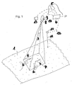
Ein Ausführungsbeispiel der Erfindung wird nachfolgend anhand der Zeichnung näher erläutert. Die einzige Figur zeigt im Einzelnen:
- Fig. 1:
- eine schematische Darstellung einer Vorrichtung zur Durchführung des erfindungsgemäßen Verfahrens.
- Fig. 1:
- a schematic representation of an apparatus for performing the method according to the invention.
In der
Erfindungsgemäß wird dieses Staubkorn 2 jedoch nicht nur in zwei unmittelbar aufeinanderfolgenden Kamerabildern sondern in der Regel in einer Sequenz mehrerer Bilder mehrfach erfasst. Außerdem werden in einem Bild erfindungsgemäß regelmäßig eine große Anzahl verschiedener und eindeutig unterscheidbarer Objekte identifiziert, also beispielsweise fünf Staubkörner, ein Blatt, vier Luftblasen, etc., die sich innerhalb eines durch einen Rahmen 7 angedeuteten Blickwinkelbereichs der Kamera 3 befinden. Jedem der identifizierten Objekte wird mindestens eine, in der Regel mehrere lokale Positionen (x, y) auf der Gewässeroberfläche zugeordnet. Für diese werden jeweils die Absolutbeträge und die Richtungen der hier momentan vorherrschenden Oberflächengeschwindigkeiten v0(x,y) des Gewässers bestimmt.According to the invention, however, this dust grain 2 is not only detected several times in two directly consecutive camera images but as a rule in a sequence of several images. In addition, according to the invention, a large number of different and clearly distinguishable objects are regularly identified in an image, for example five dust grains, one sheet, four air bubbles, etc., which are located within a viewing angle range of the camera 3 indicated by a frame 7. Each of the identified objects is assigned at least one, usually several local positions (x, y) on the surface of the water. For each of these, the absolute values and the directions of the surface velocities v 0 (x, y) currently prevailing here of the water are determined.
In berührungsloser Weise und in sehr kurzer Zeit werden erfindungsgemäß für sehr viele einzelne Positionen (x, y) des mit Hilfe der Kamera 3 erfassten Blickwinkelbereichs des Gewässers die jeweils vorherrschenden Oberflächengeschwindigkeiten v0(x,y) ermittelt. Insbesondere bei tiedebeeinflussten Gewässern ist die Vorrichtung in der Lage, mittels des erfindungsgemäßen Verfahrens zuverlässig Durchflussmengen zu bestimmen, selbst bei sehr geringen, keinen oder negativen Oberflächengeschwindigkeiten. Die Kamera 3 kann beispielsweise auf einer Brücke angebracht sein. In diesem Fall kann die Kamera 3 senkrecht nach unten oder geneigt ausgerichtet sein. Nicht dargestellt ist eine Befestigung der Vorrichtung auf einem Ausleger, einem Mast, einem Pfahl am Ufer oder dergleichen. Nicht dargestellt ist ebenfalls die optionale Verwendung mehrerer Kameras und /oder die gezielte computergesteuerte Veränderung der Kameraausrichtungen und/oder Objektivbrennweiten. Dargestellt ist weiterhin ein Scheinwerfer 13, der bei Dunkelheit die Funktionsfähigkeit der Vorrichtung gewährleistet und vorzugsweise ein Infrarotscheinwerfer ist. Der Scheinwerfer 13 leuchtet den erfassten Bildbereich 7 so aus, dass auch bei geringer Helligkeit oder völliger Dunkelheit die momentanen Oberflächengeschwindigkeiten in der erläuterten Weise erfasst werden.In a contactless manner and in a very short time, the respective prevailing surface velocities v 0 (x, y) are determined according to the invention for a very large number of individual positions (x, y) of the viewing angle range of the body of water detected with the aid of the camera 3. Particularly in the case of restricted waters, the device is able to reliably determine flow rates by means of the method according to the invention, even at very low, no or negative surface speeds. The camera 3 may be mounted on a bridge, for example. In this case, the camera 3 may be oriented vertically downwards or inclined. Not shown is an attachment of the device on a boom, a mast, a pole on the shore or the like. Not shown is also the optional use of multiple cameras and / or the targeted computer-controlled change in camera orientation and / or lens focal lengths. Shown is still a headlight 13, which ensures the functionality of the device in the dark and is preferably an infrared headlight. The headlight 13 illuminates the captured image area 7 so that even at low brightness or in complete darkness, the instantaneous surface velocities are detected in the manner explained.
Der Flüssigkeitsstand, d. h. die Höhe der Wasseroberfläche 1 über einem festen Niveau wird durch einen Flüssigkeitsstandssensor 10 ermittelt, der mittels eines nicht gezeigten Halters oder Gestells an der Brücke oder einer sonstigen ortsfesten Position befestigt ist. Vom Flüssigkeitssensor 10 geht ein Signal 11 zur Wasseroberfläche 1 aus, wobei das Signal beispielsweise ein Ultraschall- oder ein Radarsignal sein kann, welches von der Wasseroberfläche 1 reflektiert und vom Flüssigkeitssensor 10 registriert wird, um den Abstand zwischen dem Flüssigkeitssensor 10 und der Wasseroberfläche 1 zu bestimmen. Der Flüssigkeitssensor 10 ist über eine Verbindung 12 ebenfalls mit dem Computer 4 verbunden. Er kann auch nach jedem anderen bekannten Verfahren arbeiten. Hierzu können z.B. Drucksonden, Einperlsonden, Schwimmer, Winkelcodierer oder andere bekannte Flüssigkeitsstandssensoren eingesetzt werden.The liquid level, d. H. the height of the
Insbesondere bei Batteriebetrieb kann die Apparatur zur Einsparung von elektrischer Energie nach Ermittlung von Oberflächengeschwindigkeiten für eine gewisse Zeit vorübergehend in einen Ruhezustand versetzt werden. Dies ist deshalb möglich, weil sich die Fließgeschwindigkeit des Gewässers in der Regel nicht kurzfristig ändert. So genügt es in der Praxis häufig, wenn jede Viertelstunde eine Messsequenz durchgeführt wird. Diese dauert typischerweise nur einige Sekunden, so dass sich an eine einige Sekunden dauernde Aktivphase eine ca. 14 bis 15 minütige Ruhephase anschließt. Hierdurch wird die Batterielaufzeit vervielfacht, im vorliegenden Beispiel auf mindestens das 15-fache. Selbstverständlich kann auch eine fünf- oder mehrminütige Messung von einer entsprechend reduzierten oder verlängerten Ruhephase gefolgt werden. Bei anderen Anwendungen, bei denen sich die Fließgeschwindigkeit der Flüssigkeit schnell ändert, sind gänzlich andere Ruhe- und Aktivphasendauern erforderlich, die von der erfindungsgemäßen Vorrichtung ohne Weiteres umgesetzt werden können. Solche Anwendungen könnten beispielsweise Rohrleitungen sein, die chargenweise Flüssigkeiten transportieren.In particular, in battery operation, the apparatus for saving electrical energy after a determination of surface speeds for a certain time temporarily be put into a resting state. This is possible because the flow velocity of the water usually does not change in the short term. So it is often enough in practice, if every quarter of an hour a measurement sequence is performed. This typically only takes a few seconds, so that a few seconds lasting active phase is followed by a rest period of about 14 to 15 minutes. As a result, the battery life is multiplied, in this example, at least 15 times. Of course, a five or more minute measurement can be followed by a correspondingly reduced or prolonged rest period. In other applications where the flow rate of the liquid changes rapidly, completely different resting and active phase durations are required, which can be implemented by the device according to the invention readily. Such applications could be, for example, pipelines that carry liquid in batches.
- 11
- Flüssigkeitsoberflächeliquid surface
- 22
- Objektobject
- 33
- Kameracamera
- 44
- Computercomputer
- 55
- Verbindungconnection
- 66
- Geschwindigkeitspeed
- 77
- BlickwinkelbereichViewing angle
- 88th
- Objektivlens
- 99
- Blickwinkelperspective
- 1010
- FlüssigkeitsstandssensorLiquid level sensor
- 1111
- Signalsignal
- 1212
- Verbindungconnection
- 1313
- Scheinwerferheadlights
- 1414
- Schwenk-/NeigekopfPan / Tilt
Claims (15)
Priority Applications (2)
| Application Number | Priority Date | Filing Date | Title |
|---|---|---|---|
| SI200831656A SI2034278T1 (en) | 2007-09-04 | 2008-07-22 | Method and device for determining the flow rate of flowing water |
| HRP20161000TT HRP20161000T1 (en) | 2007-09-04 | 2016-08-09 | Method and device for determining the flow rate of flowing water |
Applications Claiming Priority (1)
| Application Number | Priority Date | Filing Date | Title |
|---|---|---|---|
| DE102007041717A DE102007041717A1 (en) | 2007-09-04 | 2007-09-04 | Method and device for determining the surface velocities and the flow rate of liquids in pipelines, open or closed channels and bodies of water |
Publications (3)
| Publication Number | Publication Date |
|---|---|
| EP2034278A2 true EP2034278A2 (en) | 2009-03-11 |
| EP2034278A3 EP2034278A3 (en) | 2011-05-18 |
| EP2034278B1 EP2034278B1 (en) | 2016-05-25 |
Family
ID=40239760
Family Applications (1)
| Application Number | Title | Priority Date | Filing Date |
|---|---|---|---|
| EP08013142.8A Not-in-force EP2034278B1 (en) | 2007-09-04 | 2008-07-22 | Method and device for determining the flow rate of flowing water |
Country Status (5)
| Country | Link |
|---|---|
| EP (1) | EP2034278B1 (en) |
| JP (1) | JP2009063578A (en) |
| DE (1) | DE102007041717A1 (en) |
| HR (1) | HRP20161000T1 (en) |
| SI (1) | SI2034278T1 (en) |
Cited By (8)
| Publication number | Priority date | Publication date | Assignee | Title |
|---|---|---|---|---|
| CN102735867A (en) * | 2012-06-01 | 2012-10-17 | 华南理工大学 | Raindrop terminal velocity photographic surveying method |
| EP2589936A3 (en) * | 2011-11-03 | 2015-03-11 | FiW e.V. Forschungsinstitut für Wasser- und Abfallwirtschaft | Method for measuring the volume flow of a liquid flowing in a channel, and device for carrying out the same |
| JP2015127669A (en) * | 2013-12-27 | 2015-07-09 | 独立行政法人国立高等専門学校機構 | Water flow observation method |
| CN104777327A (en) * | 2015-03-17 | 2015-07-15 | 河海大学 | Time-space image speed measuring system and method based on auxiliary laser calibration |
| CN107246896A (en) * | 2017-07-20 | 2017-10-13 | 山东省水利勘测设计院 | A kind of intelligence, removable open channel flow rate monitor and its monitoring method |
| CN104535794B (en) * | 2015-01-16 | 2018-03-20 | 中国水利水电科学研究院 | A kind of flow rate of thin water flow measuring system and method |
| CN113720401A (en) * | 2021-09-27 | 2021-11-30 | 成都市环境应急指挥保障中心 | Open channel flow measurement system and method based on underwater particle velocity measurement |
| CN116047112A (en) * | 2021-10-28 | 2023-05-02 | 华为技术有限公司 | Method, device and storage medium for measuring fluid surface velocity |
Families Citing this family (7)
| Publication number | Priority date | Publication date | Assignee | Title |
|---|---|---|---|---|
| TW201500735A (en) * | 2013-06-18 | 2015-01-01 | Nat Applied Res Laboratories | Method of mobile image identification for flow velocity and apparatus thereof |
| CN104535126B (en) * | 2015-01-16 | 2018-01-26 | 中国水利水电科学研究院 | A system and method for measuring river flow in dry season |
| CN105547638B (en) * | 2015-12-30 | 2018-03-27 | 中国水利水电科学研究院 | A kind of sheet flow roll wave measuring system and method based on pressure sensor |
| CN105444987B (en) * | 2015-12-30 | 2018-03-06 | 中国水利水电科学研究院 | A kind of sheet flow roll wave measuring system and method based on high definition photography |
| CN108847097A (en) * | 2018-04-27 | 2018-11-20 | 吴爱兵 | A kind of physics teaching water flow measurement device |
| KR102104639B1 (en) * | 2019-03-12 | 2020-04-27 | 주식회사 영국전자 | Flow velocity and fluid flow measurement system through distance measurement method |
| KR102218310B1 (en) * | 2019-11-07 | 2021-02-23 | 강원대학교산학협력단 | Flow measurement device using image sensor |
Citations (4)
| Publication number | Priority date | Publication date | Assignee | Title |
|---|---|---|---|---|
| JPH0674797A (en) | 1991-09-09 | 1994-03-18 | Kyowa Gijutsu Kk | Flow measuring method for river |
| DE4320295A1 (en) | 1993-01-25 | 1994-07-28 | Christian Dipl Ing Koelling | Method and device for measuring the flow in partially or fully filled pipes and open channels |
| DE4313682A1 (en) | 1993-04-22 | 1994-10-27 | Wolfgang Dipl Ing Frey | Method for the visual determination and measurement of the discharge of liquids flowing slowly and with a free level, using air bubbles as measuring medium, and an arrangement for carrying out the method |
| WO2001051897A1 (en) | 2000-01-10 | 2001-07-19 | Optical Flow Systems Ltd | Measurement of flow characteristics of fluent material |
Family Cites Families (11)
| Publication number | Priority date | Publication date | Assignee | Title |
|---|---|---|---|---|
| DE1045115B (en) * | 1955-03-23 | 1958-11-27 | Joachim Thon Dipl Ing | Method and device for measuring discharge in open channels |
| JPS60263863A (en) * | 1984-06-12 | 1985-12-27 | Asia Kosoku Kk | Monitoring method of surface flow velocity distribution by stereoscopic image |
| JPS63229373A (en) * | 1987-03-18 | 1988-09-26 | Kensetsusho Tohoku Chiho Kensetsu Kyokucho | Measurement of flow velocity of liquid surface |
| DE4016529C1 (en) * | 1990-05-22 | 1991-11-07 | Turbo-Werk Messtechnik Gmbh, 5000 Koeln, De | Flowmeter for open duct - has flow sensor movable across channel to supply computer with flow speeds measured at several points |
| JPH04138321A (en) * | 1990-09-29 | 1992-05-12 | Tokimec Inc | Flow rate measuring apparatus |
| US5170438A (en) * | 1991-03-22 | 1992-12-08 | Graham Fiber Glass Limited | Method and apparatus for determining the flow rate of a viscous fluid stream |
| DE4408072C2 (en) * | 1994-02-01 | 1997-11-20 | Deutsche Forsch Luft Raumfahrt | Use of an electronic high-speed camera in a method for determining flow velocities in a flow |
| JPH09152443A (en) * | 1995-11-29 | 1997-06-10 | Aisin A W Kogyo Kk | Method and apparatus for measuring flow velocity by particle image |
| JPH11173886A (en) * | 1997-12-11 | 1999-07-02 | Tokimec Inc | Flow velocity measuring apparatus and flow rate measuring apparatus |
| JP4025161B2 (en) * | 2002-09-25 | 2007-12-19 | アジア航測株式会社 | Flow velocity distribution measurement system, flow velocity distribution measurement method, flow velocity distribution measurement program, flow rate measurement system, flow rate measurement method, and flow rate measurement program |
| JP5318328B2 (en) * | 2006-02-10 | 2013-10-16 | 三菱電機株式会社 | Flow velocity measuring device |
-
2007
- 2007-09-04 DE DE102007041717A patent/DE102007041717A1/en not_active Withdrawn
-
2008
- 2008-07-22 EP EP08013142.8A patent/EP2034278B1/en not_active Not-in-force
- 2008-07-22 SI SI200831656A patent/SI2034278T1/en unknown
- 2008-09-03 JP JP2008226528A patent/JP2009063578A/en active Pending
-
2016
- 2016-08-09 HR HRP20161000TT patent/HRP20161000T1/en unknown
Patent Citations (4)
| Publication number | Priority date | Publication date | Assignee | Title |
|---|---|---|---|---|
| JPH0674797A (en) | 1991-09-09 | 1994-03-18 | Kyowa Gijutsu Kk | Flow measuring method for river |
| DE4320295A1 (en) | 1993-01-25 | 1994-07-28 | Christian Dipl Ing Koelling | Method and device for measuring the flow in partially or fully filled pipes and open channels |
| DE4313682A1 (en) | 1993-04-22 | 1994-10-27 | Wolfgang Dipl Ing Frey | Method for the visual determination and measurement of the discharge of liquids flowing slowly and with a free level, using air bubbles as measuring medium, and an arrangement for carrying out the method |
| WO2001051897A1 (en) | 2000-01-10 | 2001-07-19 | Optical Flow Systems Ltd | Measurement of flow characteristics of fluent material |
Cited By (10)
| Publication number | Priority date | Publication date | Assignee | Title |
|---|---|---|---|---|
| EP2589936A3 (en) * | 2011-11-03 | 2015-03-11 | FiW e.V. Forschungsinstitut für Wasser- und Abfallwirtschaft | Method for measuring the volume flow of a liquid flowing in a channel, and device for carrying out the same |
| CN102735867A (en) * | 2012-06-01 | 2012-10-17 | 华南理工大学 | Raindrop terminal velocity photographic surveying method |
| CN102735867B (en) * | 2012-06-01 | 2013-12-25 | 华南理工大学 | Raindrop terminal velocity photographic surveying method |
| JP2015127669A (en) * | 2013-12-27 | 2015-07-09 | 独立行政法人国立高等専門学校機構 | Water flow observation method |
| CN104535794B (en) * | 2015-01-16 | 2018-03-20 | 中国水利水电科学研究院 | A kind of flow rate of thin water flow measuring system and method |
| CN104777327A (en) * | 2015-03-17 | 2015-07-15 | 河海大学 | Time-space image speed measuring system and method based on auxiliary laser calibration |
| CN104777327B (en) * | 2015-03-17 | 2018-03-20 | 河海大学 | Time-space image velocity-measuring system and method based on laser assisted demarcation |
| CN107246896A (en) * | 2017-07-20 | 2017-10-13 | 山东省水利勘测设计院 | A kind of intelligence, removable open channel flow rate monitor and its monitoring method |
| CN113720401A (en) * | 2021-09-27 | 2021-11-30 | 成都市环境应急指挥保障中心 | Open channel flow measurement system and method based on underwater particle velocity measurement |
| CN116047112A (en) * | 2021-10-28 | 2023-05-02 | 华为技术有限公司 | Method, device and storage medium for measuring fluid surface velocity |
Also Published As
| Publication number | Publication date |
|---|---|
| EP2034278B1 (en) | 2016-05-25 |
| JP2009063578A (en) | 2009-03-26 |
| EP2034278A3 (en) | 2011-05-18 |
| SI2034278T1 (en) | 2016-09-30 |
| DE102007041717A1 (en) | 2009-03-05 |
| HRP20161000T1 (en) | 2016-10-21 |
Similar Documents
| Publication | Publication Date | Title |
|---|---|---|
| EP2034278B1 (en) | Method and device for determining the flow rate of flowing water | |
| DE102013013082B4 (en) | BLIND SPOT WARNING SYSTEM AND BLIND SPOT WARNING METHODS | |
| DE69701740T2 (en) | METHOD AND DEVICE FOR DETECTING TRAFFIC TRANSFERS WITH A DYNAMIC TARGET ARRANGEMENT | |
| DE69302975T2 (en) | Vehicle position detection system on a lane | |
| EP2467291B1 (en) | Method and controller for a robust detection of a vehicle lane change | |
| DE102018104243B3 (en) | Method and system for detecting parking spaces suitable for a vehicle | |
| AT507035A1 (en) | SYSTEM AND METHOD FOR COLLISION PREVENTION | |
| DE102004003850A1 (en) | Method for detecting markings on a roadway | |
| DE102007018470A1 (en) | Driver assistance system and method for object plausibility | |
| WO2015113678A1 (en) | Method and device for determining the position of a vehicle | |
| EP2200881B1 (en) | Method for estimating the relative movement of video objects and driver assistance system for motor vehicles | |
| DE19720764A1 (en) | Traffic detecting method for motor vehicle | |
| EP2083209A1 (en) | Security system for contactless measurement of paths and/or speeds | |
| EP3898368B1 (en) | Method and system for determining a corrected trajectory of a vehicle | |
| DE102013217486B4 (en) | Method for representing a vehicle's environment in an occupancy grid | |
| DE102016105413A1 (en) | SPEED MEASURING METHOD AND SPEED MEASURING ARRANGEMENT | |
| WO2009013052A2 (en) | Method and device for sensing a lane with a driver assistance system | |
| EP1136826A2 (en) | Device for speed measurement | |
| DE102007063508A1 (en) | Movement parameter e.g. speed, detecting method for rail vehicle, involves evaluating individual images that partially overlap and are subsequent to each other, and limiting images on narrow band such that overlapping is minimized | |
| DE102011107663B4 (en) | Method and device for the dynamic control of a signaling system | |
| EP2149055B1 (en) | Method for generating target tracks | |
| DE10160299A1 (en) | Method and system for detecting at least one object | |
| EP2254104B1 (en) | Method for automatic recognition of a change in a situation | |
| DE4320295A1 (en) | Method and device for measuring the flow in partially or fully filled pipes and open channels | |
| DE102005003194A1 (en) | Motor vehicle driver assistance system, has comparator to compare objects` absolute velocities and threshold values, which vary as function of factors that influences objects` relative velocities and vehicle velocity determination accuracy |
Legal Events
| Date | Code | Title | Description |
|---|---|---|---|
| PUAI | Public reference made under article 153(3) epc to a published international application that has entered the european phase |
Free format text: ORIGINAL CODE: 0009012 |
|
| AK | Designated contracting states |
Kind code of ref document: A2 Designated state(s): AT BE BG CH CY CZ DE DK EE ES FI FR GB GR HR HU IE IS IT LI LT LU LV MC MT NL NO PL PT RO SE SI SK TR |
|
| AX | Request for extension of the european patent |
Extension state: AL BA MK RS |
|
| PUAL | Search report despatched |
Free format text: ORIGINAL CODE: 0009013 |
|
| AK | Designated contracting states |
Kind code of ref document: A3 Designated state(s): AT BE BG CH CY CZ DE DK EE ES FI FR GB GR HR HU IE IS IT LI LT LU LV MC MT NL NO PL PT RO SE SI SK TR |
|
| AX | Request for extension of the european patent |
Extension state: AL BA MK RS |
|
| 17P | Request for examination filed |
Effective date: 20111118 |
|
| AKX | Designation fees paid |
Designated state(s): AT BE BG CH CY CZ DE DK EE ES FI FR GB GR HR HU IE IS IT LI LT LU LV MC MT NL NO PL PT RO SE SI SK TR |
|
| 17Q | First examination report despatched |
Effective date: 20140127 |
|
| GRAP | Despatch of communication of intention to grant a patent |
Free format text: ORIGINAL CODE: EPIDOSNIGR1 |
|
| INTG | Intention to grant announced |
Effective date: 20160212 |
|
| GRAS | Grant fee paid |
Free format text: ORIGINAL CODE: EPIDOSNIGR3 |
|
| GRAA | (expected) grant |
Free format text: ORIGINAL CODE: 0009210 |
|
| AK | Designated contracting states |
Kind code of ref document: B1 Designated state(s): AT BE BG CH CY CZ DE DK EE ES FI FR GB GR HR HU IE IS IT LI LT LU LV MC MT NL NO PL PT RO SE SI SK TR |
|
| REG | Reference to a national code |
Ref country code: GB Ref legal event code: FG4D Free format text: NOT ENGLISH |
|
| REG | Reference to a national code |
Ref country code: CH Ref legal event code: EP |
|
| REG | Reference to a national code |
Ref country code: IE Ref legal event code: FG4D Free format text: LANGUAGE OF EP DOCUMENT: GERMAN Ref country code: AT Ref legal event code: REF Ref document number: 802690 Country of ref document: AT Kind code of ref document: T Effective date: 20160615 |
|
| REG | Reference to a national code |
Ref country code: DE Ref legal event code: R096 Ref document number: 502008014236 Country of ref document: DE |
|
| REG | Reference to a national code |
Ref country code: FR Ref legal event code: PLFP Year of fee payment: 9 |
|
| REG | Reference to a national code |
Ref country code: CH Ref legal event code: NV Representative=s name: BOVARD AG, CH |
|
| REG | Reference to a national code |
Ref country code: HR Ref legal event code: TUEP Ref document number: P20161000 Country of ref document: HR |
|
| REG | Reference to a national code |
Ref country code: NL Ref legal event code: FP |
|
| REG | Reference to a national code |
Ref country code: LT Ref legal event code: MG4D |
|
| REG | Reference to a national code |
Ref country code: HR Ref legal event code: T1PR Ref document number: P20161000 Country of ref document: HR |
|
| PG25 | Lapsed in a contracting state [announced via postgrant information from national office to epo] |
Ref country code: NO Free format text: LAPSE BECAUSE OF FAILURE TO SUBMIT A TRANSLATION OF THE DESCRIPTION OR TO PAY THE FEE WITHIN THE PRESCRIBED TIME-LIMIT Effective date: 20160825 Ref country code: LT Free format text: LAPSE BECAUSE OF FAILURE TO SUBMIT A TRANSLATION OF THE DESCRIPTION OR TO PAY THE FEE WITHIN THE PRESCRIBED TIME-LIMIT Effective date: 20160525 Ref country code: FI Free format text: LAPSE BECAUSE OF FAILURE TO SUBMIT A TRANSLATION OF THE DESCRIPTION OR TO PAY THE FEE WITHIN THE PRESCRIBED TIME-LIMIT Effective date: 20160525 |
|
| PG25 | Lapsed in a contracting state [announced via postgrant information from national office to epo] |
Ref country code: SE Free format text: LAPSE BECAUSE OF FAILURE TO SUBMIT A TRANSLATION OF THE DESCRIPTION OR TO PAY THE FEE WITHIN THE PRESCRIBED TIME-LIMIT Effective date: 20160525 Ref country code: PT Free format text: LAPSE BECAUSE OF FAILURE TO SUBMIT A TRANSLATION OF THE DESCRIPTION OR TO PAY THE FEE WITHIN THE PRESCRIBED TIME-LIMIT Effective date: 20160926 Ref country code: GR Free format text: LAPSE BECAUSE OF FAILURE TO SUBMIT A TRANSLATION OF THE DESCRIPTION OR TO PAY THE FEE WITHIN THE PRESCRIBED TIME-LIMIT Effective date: 20160826 Ref country code: LV Free format text: LAPSE BECAUSE OF FAILURE TO SUBMIT A TRANSLATION OF THE DESCRIPTION OR TO PAY THE FEE WITHIN THE PRESCRIBED TIME-LIMIT Effective date: 20160525 Ref country code: ES Free format text: LAPSE BECAUSE OF FAILURE TO SUBMIT A TRANSLATION OF THE DESCRIPTION OR TO PAY THE FEE WITHIN THE PRESCRIBED TIME-LIMIT Effective date: 20160525 |
|
| PG25 | Lapsed in a contracting state [announced via postgrant information from national office to epo] |
Ref country code: BE Free format text: LAPSE BECAUSE OF NON-PAYMENT OF DUE FEES Effective date: 20160731 |
|
| PG25 | Lapsed in a contracting state [announced via postgrant information from national office to epo] |
Ref country code: CZ Free format text: LAPSE BECAUSE OF FAILURE TO SUBMIT A TRANSLATION OF THE DESCRIPTION OR TO PAY THE FEE WITHIN THE PRESCRIBED TIME-LIMIT Effective date: 20160525 Ref country code: EE Free format text: LAPSE BECAUSE OF FAILURE TO SUBMIT A TRANSLATION OF THE DESCRIPTION OR TO PAY THE FEE WITHIN THE PRESCRIBED TIME-LIMIT Effective date: 20160525 Ref country code: RO Free format text: LAPSE BECAUSE OF FAILURE TO SUBMIT A TRANSLATION OF THE DESCRIPTION OR TO PAY THE FEE WITHIN THE PRESCRIBED TIME-LIMIT Effective date: 20160525 Ref country code: SK Free format text: LAPSE BECAUSE OF FAILURE TO SUBMIT A TRANSLATION OF THE DESCRIPTION OR TO PAY THE FEE WITHIN THE PRESCRIBED TIME-LIMIT Effective date: 20160525 Ref country code: DK Free format text: LAPSE BECAUSE OF FAILURE TO SUBMIT A TRANSLATION OF THE DESCRIPTION OR TO PAY THE FEE WITHIN THE PRESCRIBED TIME-LIMIT Effective date: 20160525 |
|
| PG25 | Lapsed in a contracting state [announced via postgrant information from national office to epo] |
Ref country code: PL Free format text: LAPSE BECAUSE OF FAILURE TO SUBMIT A TRANSLATION OF THE DESCRIPTION OR TO PAY THE FEE WITHIN THE PRESCRIBED TIME-LIMIT Effective date: 20160525 |
|
| REG | Reference to a national code |
Ref country code: DE Ref legal event code: R097 Ref document number: 502008014236 Country of ref document: DE |
|
| PG25 | Lapsed in a contracting state [announced via postgrant information from national office to epo] |
Ref country code: MC Free format text: LAPSE BECAUSE OF FAILURE TO SUBMIT A TRANSLATION OF THE DESCRIPTION OR TO PAY THE FEE WITHIN THE PRESCRIBED TIME-LIMIT Effective date: 20160525 |
|
| PLBE | No opposition filed within time limit |
Free format text: ORIGINAL CODE: 0009261 |
|
| STAA | Information on the status of an ep patent application or granted ep patent |
Free format text: STATUS: NO OPPOSITION FILED WITHIN TIME LIMIT |
|
| 26N | No opposition filed |
Effective date: 20170228 |
|
| REG | Reference to a national code |
Ref country code: IE Ref legal event code: MM4A |
|
| REG | Reference to a national code |
Ref country code: HR Ref legal event code: ODRP Ref document number: P20161000 Country of ref document: HR Payment date: 20170713 Year of fee payment: 10 |
|
| REG | Reference to a national code |
Ref country code: FR Ref legal event code: PLFP Year of fee payment: 10 |
|
| PG25 | Lapsed in a contracting state [announced via postgrant information from national office to epo] |
Ref country code: IE Free format text: LAPSE BECAUSE OF NON-PAYMENT OF DUE FEES Effective date: 20160722 |
|
| PG25 | Lapsed in a contracting state [announced via postgrant information from national office to epo] |
Ref country code: LU Free format text: LAPSE BECAUSE OF NON-PAYMENT OF DUE FEES Effective date: 20160722 |
|
| PGFP | Annual fee paid to national office [announced via postgrant information from national office to epo] |
Ref country code: NL Payment date: 20170720 Year of fee payment: 10 |
|
| PGFP | Annual fee paid to national office [announced via postgrant information from national office to epo] |
Ref country code: IT Payment date: 20170721 Year of fee payment: 10 Ref country code: HR Payment date: 20170713 Year of fee payment: 10 Ref country code: FR Payment date: 20170720 Year of fee payment: 10 Ref country code: CH Payment date: 20170724 Year of fee payment: 10 Ref country code: DE Payment date: 20170921 Year of fee payment: 10 Ref country code: GB Payment date: 20170724 Year of fee payment: 10 |
|
| PGFP | Annual fee paid to national office [announced via postgrant information from national office to epo] |
Ref country code: AT Payment date: 20170712 Year of fee payment: 10 Ref country code: SI Payment date: 20170713 Year of fee payment: 10 |
|
| PG25 | Lapsed in a contracting state [announced via postgrant information from national office to epo] |
Ref country code: HU Free format text: LAPSE BECAUSE OF FAILURE TO SUBMIT A TRANSLATION OF THE DESCRIPTION OR TO PAY THE FEE WITHIN THE PRESCRIBED TIME-LIMIT; INVALID AB INITIO Effective date: 20080722 Ref country code: CY Free format text: LAPSE BECAUSE OF FAILURE TO SUBMIT A TRANSLATION OF THE DESCRIPTION OR TO PAY THE FEE WITHIN THE PRESCRIBED TIME-LIMIT Effective date: 20160525 |
|
| PG25 | Lapsed in a contracting state [announced via postgrant information from national office to epo] |
Ref country code: TR Free format text: LAPSE BECAUSE OF FAILURE TO SUBMIT A TRANSLATION OF THE DESCRIPTION OR TO PAY THE FEE WITHIN THE PRESCRIBED TIME-LIMIT Effective date: 20160525 Ref country code: MT Free format text: LAPSE BECAUSE OF FAILURE TO SUBMIT A TRANSLATION OF THE DESCRIPTION OR TO PAY THE FEE WITHIN THE PRESCRIBED TIME-LIMIT Effective date: 20160525 Ref country code: IS Free format text: LAPSE BECAUSE OF FAILURE TO SUBMIT A TRANSLATION OF THE DESCRIPTION OR TO PAY THE FEE WITHIN THE PRESCRIBED TIME-LIMIT Effective date: 20160525 |
|
| PG25 | Lapsed in a contracting state [announced via postgrant information from national office to epo] |
Ref country code: BG Free format text: LAPSE BECAUSE OF FAILURE TO SUBMIT A TRANSLATION OF THE DESCRIPTION OR TO PAY THE FEE WITHIN THE PRESCRIBED TIME-LIMIT Effective date: 20160525 |
|
| REG | Reference to a national code |
Ref country code: HR Ref legal event code: PBON Ref document number: P20161000 Country of ref document: HR Effective date: 20180722 |
|
| REG | Reference to a national code |
Ref country code: DE Ref legal event code: R119 Ref document number: 502008014236 Country of ref document: DE |
|
| REG | Reference to a national code |
Ref country code: CH Ref legal event code: PL |
|
| REG | Reference to a national code |
Ref country code: NL Ref legal event code: MM Effective date: 20180801 |
|
| REG | Reference to a national code |
Ref country code: AT Ref legal event code: MM01 Ref document number: 802690 Country of ref document: AT Kind code of ref document: T Effective date: 20180722 |
|
| GBPC | Gb: european patent ceased through non-payment of renewal fee |
Effective date: 20180722 |
|
| PG25 | Lapsed in a contracting state [announced via postgrant information from national office to epo] |
Ref country code: HR Free format text: LAPSE BECAUSE OF NON-PAYMENT OF DUE FEES Effective date: 20180722 Ref country code: GB Free format text: LAPSE BECAUSE OF NON-PAYMENT OF DUE FEES Effective date: 20180722 Ref country code: CH Free format text: LAPSE BECAUSE OF NON-PAYMENT OF DUE FEES Effective date: 20180731 Ref country code: AT Free format text: LAPSE BECAUSE OF NON-PAYMENT OF DUE FEES Effective date: 20180722 Ref country code: DE Free format text: LAPSE BECAUSE OF NON-PAYMENT OF DUE FEES Effective date: 20190201 Ref country code: LI Free format text: LAPSE BECAUSE OF NON-PAYMENT OF DUE FEES Effective date: 20180731 Ref country code: FR Free format text: LAPSE BECAUSE OF NON-PAYMENT OF DUE FEES Effective date: 20180731 |
|
| REG | Reference to a national code |
Ref country code: SI Ref legal event code: KO00 Effective date: 20190305 |
|
| PG25 | Lapsed in a contracting state [announced via postgrant information from national office to epo] |
Ref country code: NL Free format text: LAPSE BECAUSE OF NON-PAYMENT OF DUE FEES Effective date: 20180801 Ref country code: SI Free format text: LAPSE BECAUSE OF NON-PAYMENT OF DUE FEES Effective date: 20180723 |
|
| PG25 | Lapsed in a contracting state [announced via postgrant information from national office to epo] |
Ref country code: IT Free format text: LAPSE BECAUSE OF NON-PAYMENT OF DUE FEES Effective date: 20180722 |