EP1979134B1 - Gearing, in particular for portable electric power tools - Google Patents
Gearing, in particular for portable electric power tools Download PDFInfo
- Publication number
- EP1979134B1 EP1979134B1 EP06807826A EP06807826A EP1979134B1 EP 1979134 B1 EP1979134 B1 EP 1979134B1 EP 06807826 A EP06807826 A EP 06807826A EP 06807826 A EP06807826 A EP 06807826A EP 1979134 B1 EP1979134 B1 EP 1979134B1
- Authority
- EP
- European Patent Office
- Prior art keywords
- spindle
- output gear
- drive
- recess
- circumferential direction
- Prior art date
- Legal status (The legal status is an assumption and is not a legal conclusion. Google has not performed a legal analysis and makes no representation as to the accuracy of the status listed.)
- Not-in-force
Links
Images


Classifications
-
- B—PERFORMING OPERATIONS; TRANSPORTING
- B25—HAND TOOLS; PORTABLE POWER-DRIVEN TOOLS; MANIPULATORS
- B25F—COMBINATION OR MULTI-PURPOSE TOOLS NOT OTHERWISE PROVIDED FOR; DETAILS OR COMPONENTS OF PORTABLE POWER-DRIVEN TOOLS NOT PARTICULARLY RELATED TO THE OPERATIONS PERFORMED AND NOT OTHERWISE PROVIDED FOR
- B25F5/00—Details or components of portable power-driven tools not particularly related to the operations performed and not otherwise provided for
- B25F5/001—Gearings, speed selectors, clutches or the like specially adapted for rotary tools
-
- B—PERFORMING OPERATIONS; TRANSPORTING
- B24—GRINDING; POLISHING
- B24B—MACHINES, DEVICES, OR PROCESSES FOR GRINDING OR POLISHING; DRESSING OR CONDITIONING OF ABRADING SURFACES; FEEDING OF GRINDING, POLISHING, OR LAPPING AGENTS
- B24B23/00—Portable grinding machines, e.g. hand-guided; Accessories therefor
- B24B23/02—Portable grinding machines, e.g. hand-guided; Accessories therefor with rotating grinding tools; Accessories therefor
- B24B23/022—Spindle-locking devices, e.g. for mounting or removing the tool
-
- B—PERFORMING OPERATIONS; TRANSPORTING
- B25—HAND TOOLS; PORTABLE POWER-DRIVEN TOOLS; MANIPULATORS
- B25F—COMBINATION OR MULTI-PURPOSE TOOLS NOT OTHERWISE PROVIDED FOR; DETAILS OR COMPONENTS OF PORTABLE POWER-DRIVEN TOOLS NOT PARTICULARLY RELATED TO THE OPERATIONS PERFORMED AND NOT OTHERWISE PROVIDED FOR
- B25F5/00—Details or components of portable power-driven tools not particularly related to the operations performed and not otherwise provided for
- B25F5/006—Vibration damping means
-
- F—MECHANICAL ENGINEERING; LIGHTING; HEATING; WEAPONS; BLASTING
- F16—ENGINEERING ELEMENTS AND UNITS; GENERAL MEASURES FOR PRODUCING AND MAINTAINING EFFECTIVE FUNCTIONING OF MACHINES OR INSTALLATIONS; THERMAL INSULATION IN GENERAL
- F16D—COUPLINGS FOR TRANSMITTING ROTATION; CLUTCHES; BRAKES
- F16D3/00—Yielding couplings, i.e. with means permitting movement between the connected parts during the drive
- F16D3/02—Yielding couplings, i.e. with means permitting movement between the connected parts during the drive adapted to specific functions
- F16D3/12—Yielding couplings, i.e. with means permitting movement between the connected parts during the drive adapted to specific functions specially adapted for accumulation of energy to absorb shocks or vibration
-
- Y—GENERAL TAGGING OF NEW TECHNOLOGICAL DEVELOPMENTS; GENERAL TAGGING OF CROSS-SECTIONAL TECHNOLOGIES SPANNING OVER SEVERAL SECTIONS OF THE IPC; TECHNICAL SUBJECTS COVERED BY FORMER USPC CROSS-REFERENCE ART COLLECTIONS [XRACs] AND DIGESTS
- Y10—TECHNICAL SUBJECTS COVERED BY FORMER USPC
- Y10T—TECHNICAL SUBJECTS COVERED BY FORMER US CLASSIFICATION
- Y10T74/00—Machine element or mechanism
- Y10T74/19—Gearing
- Y10T74/19637—Gearing with brake means for gearing
Definitions
- the invention relates to a transmission, in particular for electric hand tool machines, preferably for angle grinders.
- a manually operated locking device spindle lock
- Pressing and holding a knob will ensure that the spindle does not rotate during assembly or disassembly of the grinding wheel. This is achieved in that when the locking device is actuated, a bolt engages in a recess of the driven gear and thus secures it against rotation. Since the output gear is firmly connected to the spindle, thus the spindle is secured against rotation.
- Manual locking devices for electric hand tool machines are for example from the US 4,448,098 such as US 3,802,518 known.
- drills and rotary hammers automatic locking devices are known.
- the known locking devices lock the spindle automatically in a torque transmission from the spindle to the drive. With a torque transmission from the drive to the spindle, the spindle is released automatically.
- Such electric hand tool machines with automatic locking devices are in the DE 100 03 773 A1 as well as the US 5,016,501 described.
- the DE 41 20 617 A1 discloses a transmission which comprises a drive-side coupling portion and a driven-side coupling portion, wherein for transmitting torque, a claw on the driven-side coupling portion engages in an associated recess on the drive-side coupling portion. Between the coupling sections are clamping elements, which are provided with receptacles for elastic spring elements. In the assembled state, the elastic spring elements between the clamping elements and the claws of the driven-side coupling portion.
- the clamping elements cause a blocking of the torque transmission, if the output side, a larger torque acts as on the drive side.
- the blockage is limited to one direction of rotation, whereas no blocking takes place in the case of oppositely directed torque application.
- blocking apply internal spreading flanks of the clamping elements, the outer surfaces of the output-side coupling portion.
- the invention has for its object to provide a transmission with an automatic locking device, are reduced in the vibrations in the drive train and has a low space requirement.
- the invention is based on the idea to integrate a locking device (spindle lock) and a transmission damping together in a gearbox, in particular for angle grinders.
- the invention provides that the transmission damping is an integral part of the locking device.
- the locking device and the transmission damping form a common assembly.
- the vibrations in the drive train are inventively taken up by at least one resilient damping element which is arranged in the circumferential direction between a driving element of the driven gear and a rotatably coupled to the spindle counter-element of the locking device.
- the driving element is adjustable relative to the counter element in the circumferential direction over a limited circumferential angle. If the driven gear is acted upon by the driving gear driven by the drive with a torque, so the damping element is pressed by the driving element against the counter element in the circumferential direction, whereby the damping element elastically deformed and thus dampens vibrations in the drive train.
- the existing vibrations are due among other things to production-related tolerances.
- rubbery material may be used as the damping material. It is also conceivable to use liquids filled in small cushions, in particular viscous liquids.
- the resilient damping element engages the counter element, which is non-rotatably connected to a component of the locking device or integrally connected thereto.
- the counter-element is arranged on a clamping disc of the locking device.
- Locking bodies in particular rolling bodies, can be clamped between the clamping disk and the peripheral wall enclosing the locking device. The fact that the clamping disc is rotatably coupled to the spindle, the spindle for mounting tools, in particular of cutting discs, is secured against rotation.
- the invention provides that either the driving element or the counter element is designed as an axial extension which engages axially in a pocket.
- the pocket forms in a corresponding manner the counter element or the driving element.
- the projection projecting axially into the pocket is supported on a radial wall of the pocket.
- the counter element as a pocket and the driver element as an extension educated.
- the pocket is introduced into the output gear facing side of the clamping disc.
- the rotatably coupled to the driven gear extension is pivotable about a limited by the distance of the radial walls of the pocket circumferential circumferential direction within the pocket.
- the distance of the radial walls in the circumferential direction thus defines the circumferential angle at which the output gear is rotatable relative to the spindle.
- at least one damping element is arranged on both sides of the extension within the pocket.
- the damping material can be positioned in various ways. It is conceivable that the damping element is loosely inserted in the intermediate space between extension and pocket wall. It is also possible to firmly connect the damping elements by suitable measures, for example by vulcanization, with the driving element and / or the counter element.
- a particularly advantageous possibility of forming the locking device is that the clamping disc at its outer periphery at least a first, preferably three circumferentially spaced from one another arranged first recesses having. These first recesses extend over a peripheral portion and widen radially in a first circumferential direction (direction of rotation).
- first recesses extend over a peripheral portion and widen radially in a first circumferential direction (direction of rotation).
- rolling elements are arranged in the recesses.
- the diameter of the locking body is dimensioned such that the locking body can be clamped in the narrower region of the recess between the inner wall of the recess and the peripheral wall surrounding the locking device.
- the peripheral wall is preferably formed by the transmission housing.
- the blocking bodies are received in the wider area of the recess in such a way that the clamping disk can rotate within the peripheral wall.
- the spindle is to be additionally blockable in the opposite circumferential direction, for example for releasing the tool, at least a second, preferably three second recesses with locking bodies are provided according to the invention, with the second recesses widening in the opposite circumferential direction in the radial direction, like the first recesses.
- the spindle is unlocked when this is driven by the output gear of the, in particular electromotive, drive is provided in a further development of the invention, at least one finger extending in the radial direction, with which the locking body at a rotation of the output gear in Direction wider area of the recesses of the narrower area in the wider area are transferred and held there, so that it is prevented that the locking body wander back into the narrow recessed area and thus prevent further rotation of the spindle. If it is a gear which can be driven in both circumferential directions, the finger, depending on the direction of rotation, must move the blocking bodies in the first recesses or the blocking bodies in the second recesses in the direction of rotation. It is conceivable to associate each locking body with a separate finger which engages radially behind the respective locking body.
- both the extension and the finger is arranged on the drive plate.
- the circumferential angle over which the finger is adjustable is limited by the distance of the radial walls of the pocket into which the extension axially engages. So that the finger can displace the associated blocking body in the circumferential direction, it is advantageous if the blocking body protrudes axially out of its recess in the direction of the finger, so that the blocking body can be grasped by the finger when the finger rotates. It is also possible to make the finger bent so that it engages in the pocket.
- a transmission 1 is shown for an angle grinder.
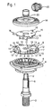
- Fig. 1 the components of the transmission 1 are shown in an exploded view.
- the transmission 1 comprises a spindle 2 with a thread 3 arranged at its free end for clamping a grinding wheel, not shown, with a clamping nut, not shown.
- the transmission also includes a ball bearing 4 with an outer bearing flange 5.
- the spindle 2 is connected by pressing with the ball bearing 4.
- the transmission 1 further comprises a clamping disc 6, which is also rotatably coupled in the assembled state by pressing with the spindle 2.
- the clamping disc 6 is held by two radially inwardly projecting and extending in the axial direction wedges 7 in two also extending in the axial direction of grooves 8 on the outer circumference of the spindle 2.
- the Clamping disc 6 is thus positively and non-positively connected to the spindle 2.
- the clamping disk 6 On the outer circumference, the clamping disk 6 has three first recesses 9 and three second recesses 10, which are offset with respect to each other.
- the first recesses 9 widen radially in a clockwise direction.
- the second recesses 10 narrow in the radial direction in a clockwise direction.
- first locking body 11 and second locking body 12 In the recesses 9, 10 of the clamping disc 6 are first locking body 11 and second locking body 12.
- the locking body 11, 12 are located on the bottom 13 of the clamping disc 6 and are freely movable in the radial and tangential direction. On the bottom 13 opposite side, the locking body 11, 12 are limited by a trained as a crown gear output gear 14.
- the blocking bodies are not arranged on a base 13 which is connected in a rotationally fixed manner to the clamping disk 6, but instead on a disk which is connected in a rotationally fixed manner to the bearing flange 5. As a result, the adjustment behavior of the locking body 11, 12 is improved.
- a drive plate 15 is arranged, which is rotatably connected by suitable measures, such as screwing or welding, with the underside of the output gear 14.
- suitable measures such as screwing or welding
- three fingers 16 which engage behind the first locking body 11 radially.
- These engage in the assembled state in associated pockets 18 in the top of the drive plate 15 a.
- the force applied to the output gear 14 torque is transmitted to the formed as pockets 18 counter-elements of the clamping plate 6.
- the torque is transmitted from the drivers 17 to the radial walls 19 of the pockets 18.
- damping elements 20 Between the radial Walls 19 and the drivers 17 are arranged in the assembled state damping elements 20, with which vibrations in the drive train can be damped. During torque transmission, the damping element deform elastically and are clamped between the walls 19 and the drivers 17. If the gear 1 shown are used for example in a drill with two directions of rotation, it is advantageous if damping elements between the walls 19 opposite walls 21 of the pockets 18 and the drivers 17 damping elements are arranged.
- the output gear 14 is freely rotatably mounted on the spindle 2. In the axial upward direction, the output gear 14 is held by a locking ring 22 in its position. Downward, the output gear 14 is located on the clamping plate 6.
- the driven gear 14 is driven via a drive gear meshing with the output gear 14 and designed as a pinion 23, which is driven by a motor driven by a shaft.
- Fig. 2 shows a ready mounted in a gear housing 24 locking device in cross-section, looking from the drive gear 23 towards ball bearing 4.
- Die Fig. 2 shows the operating state, that is, the output gear 14 and the rotatably connected to this drive plate 15 are driven in the direction indicated by the arrow rotation.
- the torque is transmitted from the output gear 14 via the drive plate 15 with driving elements 17 on the clamping plate 6 and thus on the spindle 2.
- the fingers 16 bring out the three first locking bodies 11, the total of six locking bodies 11, 12 from their locking position in the region of the radially narrow peripheral portion of the recesses 9 in the clockwise direction. This is necessary because the first locking body 11 would otherwise jam between the inner wall 25 of the first recesses 9 and the rotationally fixed peripheral wall 26 formed by the gear housing 24 (spindle lock function or locking function).
- the three second locking body 12 are pressed due to their inertia against the clockwise rear radial wall of the associated second recesses 10. This effect is further improved if the blocking bodies 11, 12 are not arranged on a base 13 which is connected in a rotationally fixed manner to the clamping disk 6, but instead on a disk which is connected in a rotationally fixed manner to the bearing flange 5.
- the inner walls 25 of these second recesses 10 are bevelled the other way around than the inner walls of the first recesses 9, so that the second locking bodies 12 move to the wider side of the recesses where they can not jam.
- FIG. 3 shows the state during tightening of the clamping nut, not shown, counterclockwise (see arrow). The drive is switched off. If a tightening torque is applied to the clamping nut, not shown, the spindle 2 and thus also the clamping disc rotates 6 a small piece in the counterclockwise direction, until the three second locking body 12 wander in their second recesses 10 along the inner walls 25 in the narrower region of the second recesses 10 and jammed between the peripheral wall 26 and the inner wall 25 of the clamping disc 6. Thus, further rotation of the spindle 2 is prevented and the tightening torque for clamping the clamping nut can be applied.
- Fig. 4 is also the drive plate 15 is not shown.
- the state when releasing the clamping nut shown is also the state when releasing the clamping nut shown.
- the three first locking body 11 move along the inner wall 25 of the first recesses 9 in the narrower area of the recesses 9 and jammed between the peripheral wall 26 and the inner walls 25 of the first recesses 9.
- the moment to release the clamping nut can be applied without that the spindle 2 rotates.
- Fig. 5 is the state according to Fig. 2 However, shown with between 17 and the radially extending walls 19 of the pockets 18 arranged damping elements 20 made of rubber-like material. In the illustrated configuration, vibrations are damped in a clockwise drive. It is conceivable in addition to 17 additional damping elements to be arranged on the damping elements 20 opposite sides of the driving elements. Due to the integration of the damping elements 20 in the introduced into the clamping plate pockets 18 of the axial height of the transmission 1 is minimal. The pockets 18 could just as well be arranged in the driver disk 15 or in the driven gear 14 in an arrangement of the driving elements 17 on the clamping disc 6.
Landscapes
- Engineering & Computer Science (AREA)
- Mechanical Engineering (AREA)
- General Engineering & Computer Science (AREA)
- Finish Polishing, Edge Sharpening, And Grinding By Specific Grinding Devices (AREA)
- Gear Transmission (AREA)
- Constituent Portions Of Griding Lathes, Driving, Sensing And Control (AREA)
- Gears, Cams (AREA)
Description
Die Erfindung betrifft ein Getriebe, insbesondere für Elektrohandwerkzeugmaschinen, bevorzugt für Winkelschleifmaschinen.The invention relates to a transmission, in particular for electric hand tool machines, preferably for angle grinders.
Bei Winkelschleifmaschinen ist in der Regel eine manuell zu betätigende Arretiereinrichtung (Spindel-Lock) am Getriebegehäuse vorgesehen. Durch Drücken und Halten eines Knopfes wird sichergestellt, dass sich die Spindel bei der Montage oder Demontage der Schleifscheibe nicht mitdreht. Dies wird dadurch erreicht, dass beim Betätigen der Arretiereinrichtung ein Bolzen in eine Vertiefung des Abtriebs-Zahnrades eingreift und dieses so gegen ein Verdrehen sichert. Da das Abtriebs-Zahnrad fest mit der Spindel verbunden ist, ist somit auch die Spindel gegen ein Verdrehen gesichert. Manuelle Arretiervorrichtungen für Elektrohandwerkzeugmaschinen sind beispielsweise aus der
Ferner sind bei Bohrmaschinen, Bohrschraubern und Bohrhämmern automatische Arretiervorrichtungen bekannt. Die bekannten Arretiervorrichtungen sperren die Spindel selbsttätig bei einer Drehmomentübertragung von der Spindel zum Antrieb. Bei einer Drehmomentübertragung vom Antrieb auf die Spindel wird die Spindel selbsttätig freigegeben. Derartige Elektrohandwerkzeugmaschinen mit automatischen Arretiereinrichtungen sind in der
Aus der
Die
Die Klemmelemente bewirken eine Sperrung der Drehmomentübertragung, falls abtriebsseitig ein größeres Drehmoment als auf der Antriebsseite wirkt. Die Sperrung ist jedoch auf eine Drehrichtung begrenzt, wohingegen bei entgegengesetzt gerichteter Drehmomentbeaufschlagung keine Sperrung erfolgt. Bei der Sperrung beaufschlagen innen liegende Spreizflanken der Klemmelemente die Außenflächen des abtriebsseitigen Kupplungsabschnittes.The clamping elements cause a blocking of the torque transmission, if the output side, a larger torque acts as on the drive side. However, the blockage is limited to one direction of rotation, whereas no blocking takes place in the case of oppositely directed torque application. When blocking apply internal spreading flanks of the clamping elements, the outer surfaces of the output-side coupling portion.
Der Erfindung liegt die Aufgabe zugrunde, ein Getriebe mit einer automatischen Arretiereinrichtung vorzuschlagen, bei dem Schwingungen im Antriebsstrang reduziert werden und das einen geringen Bauraumbedarf aufweist.The invention has for its object to provide a transmission with an automatic locking device, are reduced in the vibrations in the drive train and has a low space requirement.
Diese Aufgabe wird mit den Merkmalen des Anspruchs 1 gelöst. Vorteilhafte Ausgestaltungen der Erfindung sind in den Unteransprüchen angegeben. Der Erfindung liegt der Gedanke zugrunde, eine Arretiereinrichtung (Spindel-Lock) und eine Getriebedämpfung zusammen in einem Getriebe, insbesondere für Winkelschleifmaschinen, zu integrieren. Zur Reduzierung des axialen Bauraumbedarfs ist erfindungsgemäß vorgesehen, dass die Getriebedämpfung integraler Bestandteil der Arretiereinrichtung ist. Anders ausgedrückt, bilden die Arretiereinrichtung und die Getriebedämpfung eine gemeinsame Baugruppe. Die Schwingungen im Antriebsstrang werden erfindungsgemäß von mindestens einem federelastischen Dämpfungselement aufgenommen, das in Umfangsrichtung zwischen einem Mitnahmeelement des Abtriebs-Zahnrads und einem drehfest mit der Spindel gekoppelten Gegenelement der Arretiereinrichtung angeordnet ist. Das Mitnahmeelement ist relativ zu dem Gegenelement in Umfangsrichtung über einen begrenzten Umfangswinkel verstellbar. Wird das Abtriebs-Zahnrad von dem vom Antrieb angetriebenen Antriebszahnrad mit einem Drehmoment beaufschlagt, so wird das Dämpfungselement von dem Mitnahmeelement gegen das Gegenelement in Umfangsrichtung gedrückt, wodurch sich das Dämpfungselement elastisch verformt und somit Schwingungen im Antriebsstrang dämpft. Die vorhandenen Schwingungen sind u.a. auf fertigungsbedingte Toleranzen zurückzuführen. Durch das Vorsehen des mindestens einen Dämpfungselements werden Vibrationen herabgesetzt, Betriebsgeräusche minimiert und die beim Anlaufen des Antriebs sowie die im Betrieb auftretenden Lastspitzen an der Verzahnung reduziert. Als Dämpfungsmaterial kann beispielsweise gummiartiges Material verwendet werden. Es ist auch denkbar, in kleine Kissen abgefüllte, insbesondere viskose, Flüssigkeiten zu verwenden.This object is achieved with the features of claim 1. Advantageous embodiments of the invention are specified in the subclaims. The invention is based on the idea to integrate a locking device (spindle lock) and a transmission damping together in a gearbox, in particular for angle grinders. To reduce the axial space requirement, the invention provides that the transmission damping is an integral part of the locking device. In other words, the locking device and the transmission damping form a common assembly. The vibrations in the drive train are inventively taken up by at least one resilient damping element which is arranged in the circumferential direction between a driving element of the driven gear and a rotatably coupled to the spindle counter-element of the locking device. The driving element is adjustable relative to the counter element in the circumferential direction over a limited circumferential angle. If the driven gear is acted upon by the driving gear driven by the drive with a torque, so the damping element is pressed by the driving element against the counter element in the circumferential direction, whereby the damping element elastically deformed and thus dampens vibrations in the drive train. The existing vibrations are due among other things to production-related tolerances. By providing the at least one damping element vibrations are reduced, minimized operating noise and reduced when starting the drive and the load peaks occurring during operation of the teeth. For example, rubbery material may be used as the damping material. It is also conceivable to use liquids filled in small cushions, in particular viscous liquids.
Entscheidend zur Realisierung der Erfindung ist es, dass das federelastische Dämpfungselement an dem Gegenelement angreift, welches drehfest mit einem Bauteil der Arretierungseinrichtung oder einstückig mit diesem verbunden ist. Bevorzugt ist das Gegenelement an einer Klemmscheibe der Arretiereinrichtung angeordnet. Zwischen der Klemmscheibe und der die Arretiereinrichtung umschließenden Umfangswand können Sperrkörper, insbesondere Wälzkörper, geklemmt werden. Dadurch dass die Klemmscheibe drehfest mit der Spindel gekoppelt ist, ist auch die Spindel zur Befestigung von Werkzeugen, insbesondere von Trennscheiben, gegen ein Verdrehen gesichert.Crucial to the realization of the invention is that the resilient damping element engages the counter element, which is non-rotatably connected to a component of the locking device or integrally connected thereto. Preferably, the counter-element is arranged on a clamping disc of the locking device. Locking bodies, in particular rolling bodies, can be clamped between the clamping disk and the peripheral wall enclosing the locking device. The fact that the clamping disc is rotatably coupled to the spindle, the spindle for mounting tools, in particular of cutting discs, is secured against rotation.
Um den Bauraum in axialer Richtung möglichst gering zu halten, ist in Weiterbildung der Erfindung vorgesehen, dass entweder das Mitnahmeelement oder das Gegenelement als axialer Fortsatz ausgebildet ist, der axial in eine Tasche eingreift. Die Tasche bildet in entsprechender Weise das Gegenelement bzw. das Mitnahmeelement. Zur Drehmomentübertragung stützt sich der axial in die Tasche hinein ragende Fortsatz an einer radialen Wand der Tasche ab. Gemäß einer bevorzugten Ausführungsform ist das Gegenelement als Tasche und das Mitnehmerelement als Fortsatz ausgebildet. Die Tasche ist dabei in die dem Abtriebs-Zahnrad zugewandte Seite der Klemmscheibe eingebracht. Der drehfest mit dem Abtriebs-Zahnrad gekoppelte Fortsatz ist über einen durch den Abstand der radialen Wände der Tasche begrenzten Umfangswinkel in Umfangsrichtung innerhalb der Tasche verschwenkbar. Der Abstand der radialen Wände in Umfangsrichtung definiert somit den Umfangswinkel, in dem das Abtriebs-Zahnrad relativ zu der Spindel verdrehbar ist. Bei Getrieben, die in beide Umfangsrichtungen angetrieben werden können, ist es von Vorteil, wenn zu beiden Seiten des Fortsatzes innerhalb der Tasche jeweils mindestens ein Dämpfungselement angeordnet ist. Das Dämpfungsmaterial kann auf verschiedene Arten positioniert werden. Es ist denkbar, dass das Dämpfungselement lose in dem Zwischenraum zwischen Fortsatz und Taschenwand eingelegt ist. Ebenso ist es möglich, die Dämpfungselemente durch geeignete Maßnahmen, beispielsweise durch Aufvulkanisieren, mit dem Mitnahmeelement und/oder dem Gegenelement fest zu verbinden.In order to keep the space in the axial direction as low as possible, the invention provides that either the driving element or the counter element is designed as an axial extension which engages axially in a pocket. The pocket forms in a corresponding manner the counter element or the driving element. For torque transmission, the projection projecting axially into the pocket is supported on a radial wall of the pocket. According to a preferred embodiment, the counter element as a pocket and the driver element as an extension educated. The pocket is introduced into the output gear facing side of the clamping disc. The rotatably coupled to the driven gear extension is pivotable about a limited by the distance of the radial walls of the pocket circumferential circumferential direction within the pocket. The distance of the radial walls in the circumferential direction thus defines the circumferential angle at which the output gear is rotatable relative to the spindle. In transmissions that can be driven in both circumferential directions, it is advantageous if at least one damping element is arranged on both sides of the extension within the pocket. The damping material can be positioned in various ways. It is conceivable that the damping element is loosely inserted in the intermediate space between extension and pocket wall. It is also possible to firmly connect the damping elements by suitable measures, for example by vulcanization, with the driving element and / or the counter element.
Anstelle der Kombination aus Tasche und Fortsatz als Gegenelement und Mitnahmeelement ist es denkbar, zwei zur gegenseitigen Anlage bringbare Fortsätze vorzusehen.Instead of the combination of pocket and extension as a counter element and driving element, it is conceivable to provide two attachable to each other extensions.
Es hat sich als vorteilhaft erwiesen, das Mitnahmeelement nicht unmittelbar an dem Abtriebs-Zahnrad zu befestigen oder einstückig mit diesem auszubilden, sondern an einer drehfest mit dem Antriebs-Zahnrad gekoppelten Mitnehmerscheibe anzuordnen bzw. einstückig mit dieser auszubilden. Es ist jedoch auch die unmittelbare Anordnung des Mitnahmeelements an dem Abtriebs-Zahnrad realisierbar.It has proved to be advantageous not to attach the driving element directly to the driven gear or form integrally with this, but to arrange on a non-rotatably coupled to the drive gear drive plate and form integrally with this. However, it is also the immediate arrangement of the driving element realized on the driven gear.
Eine besonders vorteilhafte Möglichkeit der Ausbildung der Arretiereinrichtung besteht darin, dass die Klemmscheibe an ihrem Außenumfang mindestens eine erste, vorzugsweise drei im Umfangsrichtung beabstandet zueinander angeordnete erste Ausnehmungen aufweist. Diese ersten Ausnehmungen erstrecken sich über einen Umfangsabschnitt und verbreitern sich radial in eine erste Umfangsrichtung (Drehrichtung). In den Ausnehmungen sind Sperrkörper, vorzugsweise Wälzkörper, angeordnet. Der Durchmesser der Sperrkörper ist derart bemessen, dass die Sperrkörper im schmaleren Bereich der Ausnehmung zwischen der Innenwand der Ausnehmung und der die Arretiereinrichtung umgebenden Umfangswand verklemmbar sind. Die Umfangswand wird bevorzugt von dem Getriebegehäuse gebildet. Andererseits sind die Sperrkörper im breiteren Bereich der Ausnehmung derart aufgenommen, dass sich die Klemmscheibe innerhalb der Umfangswand drehen kann. Wird die Klemmscheibe in Richtung sich verbreiternder Ausnehmung gedreht, so wandern die Sperrkörper aufgrund ihrer Masseträgheit in den schmaleren Bereich und verhindern damit ein Weiterdrehen der Klemmscheibe und damit der mit der Klemmscheibe drehfest gekoppelten Spindel.A particularly advantageous possibility of forming the locking device is that the clamping disc at its outer periphery at least a first, preferably three circumferentially spaced from one another arranged first recesses having. These first recesses extend over a peripheral portion and widen radially in a first circumferential direction (direction of rotation). In the recesses locking body, preferably rolling elements are arranged. The diameter of the locking body is dimensioned such that the locking body can be clamped in the narrower region of the recess between the inner wall of the recess and the peripheral wall surrounding the locking device. The peripheral wall is preferably formed by the transmission housing. On the other hand, the blocking bodies are received in the wider area of the recess in such a way that the clamping disk can rotate within the peripheral wall. If the clamping disc is rotated in the direction of broadening recess, so the blocking body migrate due to their inertia in the narrower area and thus prevent further rotation of the clamping disc and thus the rotatably coupled to the clamping disc spindle.
Soll die Spindel zusätzlich auch in die entgegengesetzte Umfangsrichtung blockierbar sein, beispielsweise zum Lösen des Werkzeugs, so ist erfindungsgemäß mindestens eine zweite, vorzugsweise drei zweite Ausnehmungen mit Sperrkörpern vorgesehen, wobei sich die zweiten Ausnehmungen in die entgegengesetzte Umfangsrichtung in radialer Richtung verbreitern, wie die ersten Ausnehmungen.If the spindle is to be additionally blockable in the opposite circumferential direction, for example for releasing the tool, at least a second, preferably three second recesses with locking bodies are provided according to the invention, with the second recesses widening in the opposite circumferential direction in the radial direction, like the first recesses.
Damit die Spindel entsperrt wird, wenn dies über das Abtriebs-Zahnrad von dem, insbesondere elektromotorischen, Antrieb angetrieben wird, ist in Weiterbildung der Erfindung mindestens ein sich in radialer Richtung erstreckender Finger vorgesehen, mit dem die Sperrkörper bei einem Verdrehen des Abtriebs-Zahnrads in Richtung breiterem Bereich der Ausnehmungen von dem schmaleren Bereich in deren breiteren Bereich überführbar sind und dort gehalten werden, so dass verhindert wird, dass die Sperrkörper wieder in den schmaleren Ausnehmungsbereich wandern und somit ein Weiterdrehen der Spindel verhindern. Handelt es sich um ein in beide Umfangsrichtungen antreibbares Getriebe, so muss der Finger, je nach Drehrichtung, die Sperrkörper in den ersten Ausnehmungen oder die Sperrkörper in den zweiten Ausnehmungen in Drehrichtung verschieben. Es ist denkbar, jedem Sperrkörper einen eigenen Finger zuzuordnen, der den jeweiligen Sperrkörper radial hintergreift.Thus, the spindle is unlocked when this is driven by the output gear of the, in particular electromotive, drive is provided in a further development of the invention, at least one finger extending in the radial direction, with which the locking body at a rotation of the output gear in Direction wider area of the recesses of the narrower area in the wider area are transferred and held there, so that it is prevented that the locking body wander back into the narrow recessed area and thus prevent further rotation of the spindle. If it is a gear which can be driven in both circumferential directions, the finger, depending on the direction of rotation, must move the blocking bodies in the first recesses or the blocking bodies in the second recesses in the direction of rotation. It is conceivable to associate each locking body with a separate finger which engages radially behind the respective locking body.
Mit Vorteil ist sowohl der Fortsatz als auch der Finger an der Mitnehmerscheibe angeordnet. Der Umfangswinkel, über den der Finger verstellbar ist, wird von dem Abstand der radialen Wände der Tasche begrenzt, in die der Fortsatz axial hineingreift. Damit der Finger den zugehörigen Sperrkörper in Umfangsrichtung verschieben kann, ist es von Vorteil, wenn der Sperrkörper axial aus seiner Ausnehmung in Richtung des Fingers heraus ragt, so dass der Sperrkörper bei einer Drehung des Fingers von dem Finger erfasst werden kann. Es ist auch möglich, den Finger abgekröpft auszubilden, so dass dieser in die Tasche eingreift.Advantageously, both the extension and the finger is arranged on the drive plate. The circumferential angle over which the finger is adjustable is limited by the distance of the radial walls of the pocket into which the extension axially engages. So that the finger can displace the associated blocking body in the circumferential direction, it is advantageous if the blocking body protrudes axially out of its recess in the direction of the finger, so that the blocking body can be grasped by the finger when the finger rotates. It is also possible to make the finger bent so that it engages in the pocket.
Weitere Vorteile und zweckmäßige Ausführungen sind den weiteren Ansprüchen, der Figurenbeschreibung und den Zeichnungen zu entnehmen. Es zeigen:
- Fig. 1
- eine Explosionsdarstellung des erfindungsgemäßen Ge- triebes,
- Fig. 2
- das in ein Getriebegehäuse montierte Getriebe im Querschnitt, Blickrichtung vom Ritzel Richtung Spin- del, das im Uhrzeigersinn von einem Antrieb angetrie- ben ist, jedoch ohne Getriebedämpfung,
- Fig. 3
- das Getriebe im Querschnitt beim Anziehen der Spann- mutter auf der Spindel bei abgeschaltetem Antrieb, jedoch ohne Getriebedämpfung,
- Fig. 4
- das Getriebe im Querschnitt beim Lösen der Spannmut- ter von der Spindel bei abgeschaltetem Antrieb, je- doch ohne Getriebedämpfung und
- Fig. 5
- das Getriebe im Querschnitt mit in die Arretierein- richtung integrierter Getriebedämpfung.
- Fig. 1
- an exploded view of the transmission according to the invention,
- Fig. 2
- the transmission mounted in a transmission housing in cross-section, viewed from the pinion in the direction of the spindle, which is driven clockwise by a drive, but without transmission damping,
- Fig. 3
- the gear in cross-section when tightening the clamping nut on the spindle when the drive is switched off, but without gearbox damping,
- Fig. 4
- the gear in cross-section when loosening the clamping nut from the spindle when the drive is switched off, but without gearbox damping and
- Fig. 5
- the gear in cross section with integrated in the locking device transmission damping.
In den Figuren sind gleiche Bauteile und Bauteile mit gleicher Funktion mit den gleichen Bezugszeichen gekennzeichnet.In the figures, the same components and components with the same function with the same reference numerals.
In den Figuren ist ein Getriebe 1 für eine Winkelschleifmaschine dargestellt. In
Ferner umfasst das Getriebe auch ein Kugellager 4 mit einem äußeren Lagerflansch 5. Im montierten Zustand ist die Spindel 2 durch Pressung mit dem Kugellager 4 verbunden. Das Getriebe 1 umfasst weiterhin eine Klemmscheibe 6, die im montierten Zustand ebenfalls durch Pressung mit der Spindel 2 drehfest gekoppelt ist. Zusätzlich ist die Klemmscheibe 6 über zwei radial nach innen vorstehende und sich in axialer Richtung erstreckende Keile 7 in zwei sich ebenfalls in axialer Richtung erstreckenden Nuten 8 am Außenumfang der Spindel 2 gehalten. Die Klemmscheibe 6 ist somit form- und kraftschlüssig mit der Spindel 2 verbunden.Furthermore, the transmission also includes a
Am Außenumfang weist die Klemmscheibe 6 drei erste Ausnehmungen 9 und drei dazu jeweils versetzt angeordnete zweite Ausnehmungen 10 auf. Die ersten Ausnehmungen 9 verbreitern sich radial im Uhrzeigersinn. Die zweiten Ausnehmungen 10 verschmälern sich in radialer Richtung im Uhrzeigersinn. In den Ausnehmungen 9, 10 der Klemmscheibe 6 befinden sich erste Sperrkörper 11 bzw. zweite Sperrkörper 12. Die Sperrkörper 11, 12 liegen auf dem Böden 13 der Klemmscheibe 6 auf und sind in radialer sowie in tangentialer Richtung frei beweglich. Auf der dem Boden 13 gegenüber liegenden Seite werden die Sperrkörper 11, 12 durch ein als Tellerrad ausgebildetes Abtriebs-Zahnrad 14 begrenzt. Noch vorteilhafter ist es, wenn die Sperrkörper nicht auf einem drehfest mit der Klemmscheibe 6 verbundenen Boden 13 angeordnet sind, sondern stattdessen auf einer Scheibe, die drehfest mit dem Lagerflansch 5 verbunden ist. Hierdurch wird das Verstellverhalten der Sperrkörper 11, 12 verbessert.On the outer circumference, the
Zwischen Abtriebs-Zahnrad 14 und Klemmscheibe 6 ist eine Mitnehmerscheibe 15 angeordnet, die durch geeignete Maßnahmen, wie Verschrauben oder Verschweißen, mit der Unterseite des Abtriebs-Zahnrads 14 drehfest verbunden ist. In radialer Richtung erstrecken sich von der Mitnehmerscheibe 15 drei Finger 16, die die ersten Sperrkörper 11 radial hintergreifen. In axialer Richtung erstrecken sich in Richtung Klemmscheibe 6 drei als Fortsätze ausgebildete Mitnahmeelemente 17. Diese greifen im montierten Zustand in zugehörige Taschen 18 in der Oberseite der Mitnehmerscheibe 15 ein. Über die Mitnahmeelemente 17 wird das auf das Abtriebs-Zahnrad 14 aufgebrachte Drehmoment auf die als Taschen 18 ausgebildeten Gegenelemente der Klemmscheibe 6 übertragen. Das Drehmoment wird von den Mitnehmern 17 auf die radialen Wände 19 der Taschen 18 übertragen. Zwischen den radialen Wänden 19 und den Mitnehmern 17 sind im montieren Zustand Dämpfungselemente 20 angeordnet, mit denen Schwingungen im Antriebsstrang gedämpft werden können. Bei der Drehmomentübertragung verformen sich die Dämpfungselement elastisch und werden zwischen den Wänden 19 und den Mitnehmern 17 eingeklemmt. Soll das gezeigte Getriebe 1 beispielsweise in einer Bohrmaschine mit zwei Drehrichtungen eingesetzt werden, so ist es von Vorteil, wenn auch Dämpfungselemente zwischen den den Wänden 19 gegenüberliegenden Wänden 21 der Taschen 18 und den Mitnehmern 17 Dämpfungselemente angeordnet sind.Between driven
Das Abtriebs-Zahnrad 14 ist frei drehbar auf der Spindel 2 gelagert. In axialer Richtung nach oben wird das Abtriebs-Zahnrad 14 durch einen Sicherungsring 22 in seiner Position gehalten. Nach unten liegt das Abtriebs-Zahnrad 14 auf der Klemmscheibe 6 auf.The
Über ein mit dem Abtriebs-Zahnrad 14 kämmendes, als Ritzel 23 ausgebildetes Antriebszahnrad, das über eine Welle von einem elektromotorischen Antrieb angetrieben wird, wird wiederum das Abtriebs-Zahnrad 14 angetrieben.In turn, the driven
Die Funktion der Arretiereinrichtung, bestehend aus Mitnehmerscheibe 15 mit Mitnahmeelementen 17 sowie Klemmscheibe 6 mit Taschen 18, Ausnehmungen 9, 10 sowie Sperrkörpern 11, 12 wird im Folgenden anhand der
Die drei zweiten Sperrkörper 12 werden aufgrund ihrer Massenträgheit gegen die im Uhrzeigersinn hintere radiale Wand der zugehörigen zweiten Ausnehmungen 10 gedrückt. Dieser Effekt wird noch verbessert, wenn die Sperrkörper 11,12 nicht auf einem drehfest mit der Klemmscheibe 6 verbundenen Boden 13 angeordnet sind, sondern stattdessen auf einer Scheibe, die drehfest mit dem Lagerflansch 5 verbunden ist. Die Innenwände 25 dieser zweiten Ausnehmungen 10 sind andersherum abgeschrägt als die Innenwände der ersten Ausnehmungen 9, so dass die zweiten Sperrkörper 12 auf die breitere Seite der Ausnehmungen wandern, wo sie sich nicht verklemmen können.The three
In
In
In
Claims (8)
- Gearing, in particular for portable electric power tools, comprising a drive gear (23) driven by a drive and an output gear (14) which meshes with said drive gear (23) and drives a spindle (2), and comprising a locking device via which the spindle (2), for releasing and fastening tools, can be coupled in a rotationally fixed manner relative to a circumferential wall (26) enclosing the locking device and which automatically opens when torque is transmitted from the drive to the spindle (2) and automatically blocks when torque is transmitted from the spindle (2) to the drive, wherein the output gear (14) is rotatable relative to the spindle (2) over a limited circumferential angle, and a driving element (17) is coupled to the output gear (14) in a rotationally fixed manner for transmitting torque to a counter-element (18) of the locking device, said counter-element (18) being coupled to the spindle (2) in a rotationally fixed manner, and the locking device comprises at least one elastic damping element (20) which is arranged in the circumferential direction between the driving element (17) and the counter-element (18), wherein the counter-element (18) is arranged on a clamping disc (6) of the locking device, characterized in that the clamping disc (6) has on its outer circumference at least one first recess (9) widening radially in a first circumferential direction, and in that a first blocking body (11) movable radially and in both circumferential directions is arranged in the first recess (9), and in that the first blocking body (11), when torque is transmitted from the spindle (2) to the drive, blocks the spindle (2) in the first circumferential direction by becoming jammed between an inner wall (25) of the first recess (9) and the circumferential wall (26), in that at least one finger (16) coupled to the output gear (14) in a rotationally fixed manner is provided, which finger (16), when output gear (14) is driven, displaces the first blocking body (11) in the circumferential direction out of its blocking position into its release position and holds it there, and in that the first blocking body (11) projects axially from its recess (9) in the direction of finger (16).
- Gearing according to Claim 1, characterized in that the driving element (17) is designed as an axial extension and in that the counter-element (18) is designed as a pocket, or vice versa, and in that the extension (17) engages axially in the pocket (18) and is supported on a radially extending pocket wall (19, 21) for the torque transmission.
- Gearing according to Claim 1 or 2, characterized in that a damping element (20) is arranged on either side of the driving element (17), the two sides being directed in opposite circumferential directions.
- Gearing according to one of the preceding claims, characterized in that the driving element (17) is arranged on a driver disc (15) coupled to the output gear (14) in a rotationally fixed manner.
- Gearing according to one of the preceding claims, characterized in that the clamping disc (6) has on its outer circumference at least one second recess (10) widening radially in a second circumferential direction opposed to the first circumferential direction, and in that a second blocking body (12) movable radially and in both circumferential directions is arranged in the second recess (10), and in that the second blocking body (12), when torque is transmitted from the spindle (2) to the drive, blocks the spindle (2) in the second circumferential direction by becoming jammed between an inner wall (25) of the second recess (10) and the circumferential wall.
- Gearing according to Claim 5, characterized in that the finger (16) coupled to the output gear (14) in a rotationally fixed manner, when output gear (14) is driven, displaces the second blocking body (12) in the circumferential direction out of its blocking position into its release position and holds it there.
- Gearing according to Claim 6, characterized in that the extension (17) and the finger (16) are arranged on the driver disc (15), and in that the amount of play which the extension (17) has in the pocket (18) in both circumferential directions is dimensioned in such a way that the first or the second blocking body (11, 12) can be displaced in the first or the second circumferential direction out of its blocking position by means of the finger (16).
- Gearing according to one of Claims 5 to 7, characterized in that the second blocking body (12) projects axially from its recess (10) in the direction of finger (16).
Applications Claiming Priority (2)
| Application Number | Priority Date | Filing Date | Title |
|---|---|---|---|
| DE102006001985A DE102006001985A1 (en) | 2006-01-16 | 2006-01-16 | Transmission for hand-held power tools has locating device including at least one spring damping element between carrier element and counter-element |
| PCT/EP2006/068751 WO2007087909A1 (en) | 2006-01-16 | 2006-11-22 | Gearing, in particular for portable electric power tools |
Publications (2)
| Publication Number | Publication Date |
|---|---|
| EP1979134A1 EP1979134A1 (en) | 2008-10-15 |
| EP1979134B1 true EP1979134B1 (en) | 2010-07-07 |
Family
ID=37733885
Family Applications (1)
| Application Number | Title | Priority Date | Filing Date |
|---|---|---|---|
| EP06807826A Not-in-force EP1979134B1 (en) | 2006-01-16 | 2006-11-22 | Gearing, in particular for portable electric power tools |
Country Status (6)
| Country | Link |
|---|---|
| US (1) | US8534378B2 (en) |
| EP (1) | EP1979134B1 (en) |
| JP (1) | JP4928566B2 (en) |
| CN (1) | CN101360587B (en) |
| DE (2) | DE102006001985A1 (en) |
| WO (1) | WO2007087909A1 (en) |
Families Citing this family (16)
| Publication number | Priority date | Publication date | Assignee | Title |
|---|---|---|---|---|
| DE102007000313A1 (en) * | 2007-06-06 | 2008-12-11 | Hilti Aktiengesellschaft | Electric hand tool with spindle locking device |
| JP5214484B2 (en) | 2009-02-09 | 2013-06-19 | 株式会社マキタ | Electric tool |
| JP5566840B2 (en) * | 2010-10-04 | 2014-08-06 | 株式会社マキタ | Rotating tool |
| CN102466274B (en) * | 2010-11-03 | 2014-10-29 | 珠海格力电器股份有限公司 | Vertical air conditioner |
| DE102011005812A1 (en) * | 2011-03-18 | 2012-09-20 | Robert Bosch Gmbh | Machine tool braking device |
| DE102011075228B4 (en) * | 2011-05-04 | 2025-02-06 | Robert Bosch Gmbh | oscillating tool clamping device |
| DE102012205609A1 (en) * | 2012-04-04 | 2013-10-10 | Metabowerke Gmbh | Electric hand tool with spindle stop |
| CN103683637A (en) * | 2012-08-30 | 2014-03-26 | 思考电机(上海)有限公司 | Fan motor and electronic equipment |
| DE102012218833A1 (en) | 2012-10-16 | 2014-04-17 | Metabowerke Gmbh & Co | Powered hand tool and Spindelarretierung for this |
| US20140321987A1 (en) * | 2013-03-15 | 2014-10-30 | Honeywell International Inc. | Plasma actuated cascade flow vectoring |
| EP3083156B1 (en) * | 2013-12-20 | 2024-07-31 | Black & Decker, Inc. | Spindle lock assembly for power tool |
| DE102014212863B4 (en) * | 2014-07-02 | 2020-08-20 | Stabilus Gmbh | Flap control |
| DE212017000224U1 (en) * | 2016-09-30 | 2019-05-06 | Koki Holdings Co., Ltd. | Electrically powered tool |
| KR102015080B1 (en) * | 2017-11-13 | 2019-08-29 | 김다혜 | Power rotation apparatus |
| KR102097424B1 (en) * | 2019-04-08 | 2020-04-07 | 김다혜 | Torque Transmission Device |
| US12076845B2 (en) | 2022-03-14 | 2024-09-03 | Milwaukee Electric Tool Corporation | Power tool including soft-stop transmission |
Family Cites Families (28)
| Publication number | Priority date | Publication date | Assignee | Title |
|---|---|---|---|---|
| US1425616A (en) * | 1921-01-03 | 1922-08-15 | Spicer Mfg Corp | Flexible coupling |
| US2961856A (en) * | 1957-01-30 | 1960-11-29 | Int Harvester Co | Cog wheel construction |
| US3802518A (en) | 1972-03-09 | 1974-04-09 | J Albert | Ratchet implement |
| ES480783A1 (en) * | 1979-05-09 | 1980-01-16 | Damper Iberica Sa | Resilient coupling mechanism |
| US4448098A (en) | 1982-03-10 | 1984-05-15 | Katsuyuki Totsu | Electrically driven screw-driver |
| JPH0776039B2 (en) | 1986-09-03 | 1995-08-16 | 株式会社タツノ・メカトロニクス | Gas station |
| JPH068345Y2 (en) * | 1988-05-19 | 1994-03-02 | エヌティエヌ株式会社 | clutch |
| US5016501B1 (en) | 1988-07-29 | 1997-07-15 | Sb Power Tool Co | Automatic shaft lock |
| DE4120617C2 (en) | 1990-10-30 | 1994-06-01 | Brose Fahrzeugteile | Locking clutch with an output-side and an input-side coupling section |
| DE19717624A1 (en) * | 1996-05-17 | 1997-11-20 | Mitsuba Corp | Reduction transmission with impact absorption mechanism |
| US5797540A (en) * | 1997-01-27 | 1998-08-25 | Generac Corporation | Method of making a power-transmitting coupling |
| DE19730198B4 (en) | 1997-07-15 | 2004-04-15 | Scintilla Ag | shaft coupling |
| DE29715257U1 (en) | 1997-08-26 | 1997-12-04 | Atlas Copco Electric Tools GmbH, 71364 Winnenden | Driving device |
| DE19750262A1 (en) | 1997-11-13 | 1999-05-20 | Schaeffler Waelzlager Kg | Clamp lock |
| JP3003784B2 (en) * | 1998-05-11 | 2000-01-31 | 株式会社シマノ | Bicycle shock absorber |
| US6295910B1 (en) * | 1999-08-13 | 2001-10-02 | S-B Power Tool Company | Clutch assembly for use with a circular saw |
| DE19949485A1 (en) | 1999-10-14 | 2001-04-19 | Schaeffler Waelzlager Ohg | Switchable silent ratchet, e.g. to adjust vehicle seat height; has rotating clamp roller spring-biased in clamp spaces formed from clamp path casing and clamp slopes of clamp sleeve |
| JP4159214B2 (en) | 1999-11-17 | 2008-10-01 | Ntn株式会社 | Reverse input prevention clutch |
| JP2001208102A (en) | 2000-01-21 | 2001-08-03 | Ntn Corp | Reverse input prevention clutch and automatic washing machine |
| DE10003773B4 (en) | 2000-01-28 | 2005-08-25 | Scintilla Ag | Hand tool with a locking device for the drive shaft |
| EP1122390A3 (en) * | 2000-02-02 | 2009-01-21 | Asmo Co., Ltd. | Clutch and motor including such clutch |
| JP3887166B2 (en) | 2000-02-02 | 2007-02-28 | アスモ株式会社 | Clutch and motor |
| DE10059186A1 (en) | 2000-11-29 | 2002-06-06 | Mobiletron Electronics Co | Motor-operated unidirectional output device for fitting between an electrically operated tool's main shaft and a power source has swivel seating, flexible rubbery disk seatings, locking seating, locking rollers and a fixing ring |
| JP2003056596A (en) | 2001-08-09 | 2003-02-26 | Ntn Corp | Rotating device with clutch |
| US6702090B2 (en) * | 2001-03-14 | 2004-03-09 | Milwaukee Electric Tool Corporation | Power tool and spindle lock system |
| US6935006B2 (en) | 2002-12-18 | 2005-08-30 | Honeywell International, Inc. | Spun metal form used to manufacture dual alloy turbine wheel |
| DE10259519A1 (en) * | 2002-12-19 | 2004-07-01 | Robert Bosch Gmbh | Gearboxes, in particular for electric hand machine tools |
| JP4730580B2 (en) * | 2004-04-12 | 2011-07-20 | 日立工機株式会社 | Electric tool and gear device |
-
2006
- 2006-01-16 DE DE102006001985A patent/DE102006001985A1/en not_active Ceased
- 2006-11-22 CN CN200680051174.4A patent/CN101360587B/en not_active Expired - Fee Related
- 2006-11-22 WO PCT/EP2006/068751 patent/WO2007087909A1/en not_active Ceased
- 2006-11-22 US US11/993,659 patent/US8534378B2/en not_active Expired - Fee Related
- 2006-11-22 DE DE502006007394T patent/DE502006007394D1/en active Active
- 2006-11-22 JP JP2008550654A patent/JP4928566B2/en not_active Expired - Fee Related
- 2006-11-22 EP EP06807826A patent/EP1979134B1/en not_active Not-in-force
Also Published As
| Publication number | Publication date |
|---|---|
| US8534378B2 (en) | 2013-09-17 |
| WO2007087909A1 (en) | 2007-08-09 |
| US20100018736A1 (en) | 2010-01-28 |
| DE102006001985A1 (en) | 2007-07-19 |
| JP4928566B2 (en) | 2012-05-09 |
| CN101360587A (en) | 2009-02-04 |
| JP2009523973A (en) | 2009-06-25 |
| DE502006007394D1 (en) | 2010-08-19 |
| CN101360587B (en) | 2012-07-04 |
| EP1979134A1 (en) | 2008-10-15 |
Similar Documents
| Publication | Publication Date | Title |
|---|---|---|
| EP1979134B1 (en) | Gearing, in particular for portable electric power tools | |
| EP1307313B1 (en) | Hand-operated machine tool | |
| DE3510605C2 (en) | ||
| EP2655019B1 (en) | Portable power tool | |
| DE102009011184B4 (en) | driving means | |
| DE102006001986A1 (en) | Clamping device for releasably securing a disc-shaped tool | |
| DE19809133A1 (en) | Hand machine tools, in particular drill drivers | |
| DE10246711A1 (en) | Gearing device for adjusting devices in motor vehicles e.g. electric window winders or sliding roofs, has first and second gear components interlinked so as to rotate | |
| EP2101953A1 (en) | Handheld tool | |
| EP1765556B1 (en) | Percussion hammer and/or drill hammer comprising a safety coupling | |
| EP2097657A1 (en) | Torsional vibration damper comprising a sectional primary element | |
| EP0591574A1 (en) | Power driven electric handtool | |
| EP1488121A1 (en) | Device for coupling a housing arrangement of a coupling device to a rotor arrangement of an electric machine | |
| DE102008005229A1 (en) | Driving device, particularly for flap of vehicle, has fastening unit connectable with fixed component or movable component, and noise production element is provided for producing noises | |
| EP2228157A1 (en) | Screwing or drilling tool powered by an electric motor | |
| CH692276A5 (en) | Tool, in particular drill or impact drill or rotary hammer. | |
| DE19809131A1 (en) | Electric hand machine tool | |
| EP1652631B1 (en) | Motor driven power tool | |
| EP1881883B1 (en) | Motor-driven machine-tool with a locking/releasing device for the spindle | |
| EP2011608A1 (en) | Hand tool with friction clutch | |
| DE19747221C1 (en) | Torsion damper for motor vehicle clutch | |
| DE102021211648B4 (en) | shaft-hub connection | |
| DE102021213313A1 (en) | shaft-hub connection | |
| DE102016216670B4 (en) | Camshaft adjuster | |
| DE102005049433A1 (en) | Axial plug-in connection, has profile unit and counter profile unit profiled in such a manner that relative movement is provided by directly profiling profile unit and counter unit for raising torque during axially assembling |
Legal Events
| Date | Code | Title | Description |
|---|---|---|---|
| PUAI | Public reference made under article 153(3) epc to a published international application that has entered the european phase |
Free format text: ORIGINAL CODE: 0009012 |
|
| 17P | Request for examination filed |
Effective date: 20080818 |
|
| AK | Designated contracting states |
Kind code of ref document: A1 Designated state(s): DE FR GB |
|
| RBV | Designated contracting states (corrected) |
Designated state(s): DE FR GB |
|
| 17Q | First examination report despatched |
Effective date: 20090720 |
|
| GRAP | Despatch of communication of intention to grant a patent |
Free format text: ORIGINAL CODE: EPIDOSNIGR1 |
|
| DAX | Request for extension of the european patent (deleted) | ||
| GRAS | Grant fee paid |
Free format text: ORIGINAL CODE: EPIDOSNIGR3 |
|
| GRAA | (expected) grant |
Free format text: ORIGINAL CODE: 0009210 |
|
| AK | Designated contracting states |
Kind code of ref document: B1 Designated state(s): DE FR GB |
|
| REG | Reference to a national code |
Ref country code: GB Ref legal event code: FG4D Free format text: NOT ENGLISH |
|
| REF | Corresponds to: |
Ref document number: 502006007394 Country of ref document: DE Date of ref document: 20100819 Kind code of ref document: P |
|
| PLBE | No opposition filed within time limit |
Free format text: ORIGINAL CODE: 0009261 |
|
| STAA | Information on the status of an ep patent application or granted ep patent |
Free format text: STATUS: NO OPPOSITION FILED WITHIN TIME LIMIT |
|
| 26N | No opposition filed |
Effective date: 20110408 |
|
| REG | Reference to a national code |
Ref country code: DE Ref legal event code: R097 Ref document number: 502006007394 Country of ref document: DE Effective date: 20110408 |
|
| REG | Reference to a national code |
Ref country code: FR Ref legal event code: PLFP Year of fee payment: 10 |
|
| PGFP | Annual fee paid to national office [announced via postgrant information from national office to epo] |
Ref country code: GB Payment date: 20151123 Year of fee payment: 10 |
|
| PGFP | Annual fee paid to national office [announced via postgrant information from national office to epo] |
Ref country code: FR Payment date: 20151124 Year of fee payment: 10 |
|
| GBPC | Gb: european patent ceased through non-payment of renewal fee |
Effective date: 20161122 |
|
| REG | Reference to a national code |
Ref country code: FR Ref legal event code: ST Effective date: 20170731 |
|
| PG25 | Lapsed in a contracting state [announced via postgrant information from national office to epo] |
Ref country code: FR Free format text: LAPSE BECAUSE OF NON-PAYMENT OF DUE FEES Effective date: 20161130 |
|
| PG25 | Lapsed in a contracting state [announced via postgrant information from national office to epo] |
Ref country code: GB Free format text: LAPSE BECAUSE OF NON-PAYMENT OF DUE FEES Effective date: 20161122 |
|
| PGFP | Annual fee paid to national office [announced via postgrant information from national office to epo] |
Ref country code: DE Payment date: 20200124 Year of fee payment: 14 |
|
| REG | Reference to a national code |
Ref country code: DE Ref legal event code: R119 Ref document number: 502006007394 Country of ref document: DE |
|
| PG25 | Lapsed in a contracting state [announced via postgrant information from national office to epo] |
Ref country code: DE Free format text: LAPSE BECAUSE OF NON-PAYMENT OF DUE FEES Effective date: 20210601 |