EP1979009B1 - Air freshener with frame and refill holder - Google Patents
Air freshener with frame and refill holder Download PDFInfo
- Publication number
- EP1979009B1 EP1979009B1 EP07762414A EP07762414A EP1979009B1 EP 1979009 B1 EP1979009 B1 EP 1979009B1 EP 07762414 A EP07762414 A EP 07762414A EP 07762414 A EP07762414 A EP 07762414A EP 1979009 B1 EP1979009 B1 EP 1979009B1
- Authority
- EP
- European Patent Office
- Prior art keywords
- rear face
- frame
- recess
- dispenser
- reservoir
- Prior art date
- Legal status (The legal status is an assumption and is not a legal conclusion. Google has not performed a legal analysis and makes no representation as to the accuracy of the status listed.)
- Not-in-force
Links
- 239000002386 air freshener Substances 0.000 title claims 2
- 239000000463 material Substances 0.000 claims description 61
- 239000012528 membrane Substances 0.000 claims description 41
- 230000002093 peripheral effect Effects 0.000 claims description 31
- 239000003205 fragrance Substances 0.000 claims description 9
- 238000009792 diffusion process Methods 0.000 claims description 6
- 239000007789 gas Substances 0.000 claims description 3
- 239000003112 inhibitor Substances 0.000 claims 1
- 239000000077 insect repellent Substances 0.000 claims 1
- 239000002917 insecticide Substances 0.000 claims 1
- 239000012780 transparent material Substances 0.000 claims 1
- 239000003570 air Substances 0.000 description 9
- 239000004677 Nylon Substances 0.000 description 5
- 239000000203 mixture Substances 0.000 description 5
- 229920001778 nylon Polymers 0.000 description 5
- 239000002562 thickening agent Substances 0.000 description 5
- 239000012080 ambient air Substances 0.000 description 4
- 230000004048 modification Effects 0.000 description 4
- 238000012986 modification Methods 0.000 description 4
- 238000004513 sizing Methods 0.000 description 4
- 230000008901 benefit Effects 0.000 description 3
- 229920000728 polyester Polymers 0.000 description 3
- -1 polyethylene terephthalate Polymers 0.000 description 3
- 239000004743 Polypropylene Substances 0.000 description 2
- 239000000853 adhesive Substances 0.000 description 2
- 230000001070 adhesive effect Effects 0.000 description 2
- XAGFODPZIPBFFR-UHFFFAOYSA-N aluminium Chemical compound [Al] XAGFODPZIPBFFR-UHFFFAOYSA-N 0.000 description 2
- 229910052782 aluminium Inorganic materials 0.000 description 2
- 239000011888 foil Substances 0.000 description 2
- 239000011521 glass Substances 0.000 description 2
- 229920001684 low density polyethylene Polymers 0.000 description 2
- 239000004702 low-density polyethylene Substances 0.000 description 2
- 230000005012 migration Effects 0.000 description 2
- 238000013508 migration Methods 0.000 description 2
- 239000002304 perfume Substances 0.000 description 2
- 229920001155 polypropylene Polymers 0.000 description 2
- 238000007639 printing Methods 0.000 description 2
- 238000007789 sealing Methods 0.000 description 2
- 239000007787 solid Substances 0.000 description 2
- 229920001634 Copolyester Polymers 0.000 description 1
- 238000009825 accumulation Methods 0.000 description 1
- 238000004378 air conditioning Methods 0.000 description 1
- 230000008859 change Effects 0.000 description 1
- 239000004020 conductor Substances 0.000 description 1
- 238000002788 crimping Methods 0.000 description 1
- 230000003247 decreasing effect Effects 0.000 description 1
- 230000001419 dependent effect Effects 0.000 description 1
- 230000003467 diminishing effect Effects 0.000 description 1
- 230000000694 effects Effects 0.000 description 1
- 238000005530 etching Methods 0.000 description 1
- 239000005038 ethylene vinyl acetate Substances 0.000 description 1
- 238000001125 extrusion Methods 0.000 description 1
- 238000009432 framing Methods 0.000 description 1
- 238000010438 heat treatment Methods 0.000 description 1
- 238000000034 method Methods 0.000 description 1
- 239000002991 molded plastic Substances 0.000 description 1
- 238000000465 moulding Methods 0.000 description 1
- 238000009740 moulding (composite fabrication) Methods 0.000 description 1
- 239000004033 plastic Substances 0.000 description 1
- 229920003023 plastic Polymers 0.000 description 1
- 229920000139 polyethylene terephthalate Polymers 0.000 description 1
- 239000005020 polyethylene terephthalate Substances 0.000 description 1
- 230000008569 process Effects 0.000 description 1
- 229920005989 resin Polymers 0.000 description 1
- 239000011347 resin Substances 0.000 description 1
- 238000012216 screening Methods 0.000 description 1
- 239000011343 solid material Substances 0.000 description 1
- 239000000126 substance Substances 0.000 description 1
- 238000003856 thermoforming Methods 0.000 description 1
- 230000007704 transition Effects 0.000 description 1
- 238000013022 venting Methods 0.000 description 1
- 239000011800 void material Substances 0.000 description 1
Images


Classifications
-
- A—HUMAN NECESSITIES
- A61—MEDICAL OR VETERINARY SCIENCE; HYGIENE
- A61L—METHODS OR APPARATUS FOR STERILISING MATERIALS OR OBJECTS IN GENERAL; DISINFECTION, STERILISATION OR DEODORISATION OF AIR; CHEMICAL ASPECTS OF BANDAGES, DRESSINGS, ABSORBENT PADS OR SURGICAL ARTICLES; MATERIALS FOR BANDAGES, DRESSINGS, ABSORBENT PADS OR SURGICAL ARTICLES
- A61L9/00—Disinfection, sterilisation or deodorisation of air
- A61L9/015—Disinfection, sterilisation or deodorisation of air using gaseous or vaporous substances, e.g. ozone
- A61L9/04—Disinfection, sterilisation or deodorisation of air using gaseous or vaporous substances, e.g. ozone using substances evaporated in the air without heating
- A61L9/12—Apparatus, e.g. holders, therefor
-
- A—HUMAN NECESSITIES
- A01—AGRICULTURE; FORESTRY; ANIMAL HUSBANDRY; HUNTING; TRAPPING; FISHING
- A01M—CATCHING, TRAPPING OR SCARING OF ANIMALS; APPARATUS FOR THE DESTRUCTION OF NOXIOUS ANIMALS OR NOXIOUS PLANTS
- A01M1/00—Stationary means for catching or killing insects
- A01M1/20—Poisoning, narcotising, or burning insects
- A01M1/2022—Poisoning or narcotising insects by vaporising an insecticide
- A01M1/2027—Poisoning or narcotising insects by vaporising an insecticide without heating
- A01M1/2044—Holders or dispensers for liquid insecticide, e.g. using wicks
-
- A—HUMAN NECESSITIES
- A01—AGRICULTURE; FORESTRY; ANIMAL HUSBANDRY; HUNTING; TRAPPING; FISHING
- A01M—CATCHING, TRAPPING OR SCARING OF ANIMALS; APPARATUS FOR THE DESTRUCTION OF NOXIOUS ANIMALS OR NOXIOUS PLANTS
- A01M1/00—Stationary means for catching or killing insects
- A01M1/20—Poisoning, narcotising, or burning insects
- A01M1/2022—Poisoning or narcotising insects by vaporising an insecticide
- A01M1/2027—Poisoning or narcotising insects by vaporising an insecticide without heating
- A01M1/2055—Holders or dispensers for solid, gelified or impregnated insecticide, e.g. volatile blocks or impregnated pads
-
- A—HUMAN NECESSITIES
- A47—FURNITURE; DOMESTIC ARTICLES OR APPLIANCES; COFFEE MILLS; SPICE MILLS; SUCTION CLEANERS IN GENERAL
- A47G—HOUSEHOLD OR TABLE EQUIPMENT
- A47G1/00—Mirrors; Picture frames or the like, e.g. provided with heating, lighting or ventilating means
- A47G1/06—Picture frames
-
- A—HUMAN NECESSITIES
- A61—MEDICAL OR VETERINARY SCIENCE; HYGIENE
- A61L—METHODS OR APPARATUS FOR STERILISING MATERIALS OR OBJECTS IN GENERAL; DISINFECTION, STERILISATION OR DEODORISATION OF AIR; CHEMICAL ASPECTS OF BANDAGES, DRESSINGS, ABSORBENT PADS OR SURGICAL ARTICLES; MATERIALS FOR BANDAGES, DRESSINGS, ABSORBENT PADS OR SURGICAL ARTICLES
- A61L9/00—Disinfection, sterilisation or deodorisation of air
- A61L9/015—Disinfection, sterilisation or deodorisation of air using gaseous or vaporous substances, e.g. ozone
- A61L9/04—Disinfection, sterilisation or deodorisation of air using gaseous or vaporous substances, e.g. ozone using substances evaporated in the air without heating
Definitions
- the present invention generally relates to a volatile material dispensing system, and more particularly, to a refillable volatile material dispensing system.
- Volatile material dispensing systems have been used to provide fragrances to office or home settings.
- One such dispenser comprises a holder with a rectangular portion. Two opposing walls extend the length of the rectangular portion and depend from sides thereof. A ridge extends the length of the portion along a center thereof. Inwardly protruding - lips extend toward each other from ends of the opposing walls. The area enclosed by the portion, walls, and lips define a slot that can hold a solid material containing a fragrance.
- Another dispenser comprises a housing with a rectangular upper portion and a rounded lower portion.
- a rectangular channel is disposed within the rectangular upper portion.
- the channel is adapted to receive a solid perfume contained within a rectangular reservoir having a transparent permeable membrane covering one side thereof.
- a plug is disposed on a rear face of the housing to provide power to a heat conductor for volatizing the solid perfume, a lamp, and an optically sensitive element.
- Yet another dispenser comprises a scenting device adapted to function with a heating, air conditioning, or venting system.
- the device includes a first member that is rectangular in shape and made from an air permeable and relatively porous substance.
- a frame surrounds the periphery of the member and provides a rigid structure to assist in mounting the device.
- the device is inserted into a mounting means disposed adjacent an air filter.
- the mounting means comprises a U-shaped member having an inner groove for slidably receiving the frame therein.
- a display frame with a refill holder comprises a transparent block having front and rear faces.
- a U-shaped mounting member is attached to the rear face about an outer periphery of same.
- the U-shaped mounting member has an inwardly extending wall.
- a channel is formed in a space between the rear face and the inwardly extending wall.
- a protrusion is attached to the rear face of the frame, wherein at least one of the protrusion and the inwardly extending wall are configured to distance the rear face from a support surface when the frame is in a substantially horizontal position and provide a substantially unimpeded air passage adjacent the rear face.
- a volatile material dispensing system comprises a reservoir having a first surface and a vapor permeable membrane sealed to an outer periphery of the first surface.
- a volatile material is contained within the reservoir, wherein the volatile material is diffused through the membrane into an ambient atmosphere.
- a planar frame has a front face and a rear face, wherein the reservoir is releasably held within a reservoir holder disposed on the rear face of the frame.
- a protrusion is attached to the rear face of the frame, wherein at least one of the protrusion and the reservoir holder are configured to distance the membrane from a supporting surface when the frame is in a substantially horizontal position providing an air passage sufficient to impede volatile material gases from altering the supporting surface.
- a picture frame comprises a frame having front and rear faces.
- a recess is disposed within the rear face of the frame.
- a holder is disposed on the rear face of the frame.
- a dispenser is disposed within at least one of the recess of the rear face and the holder.
- the dispenser includes a reservoir and a vapor permeable membrane.
- a slot is disposed in a side wall of the frame and is configured to hold an image.
- FIG. 1 is an exploded rear isometric view of the volatile material dispensing system that includes a frame, a holder, and a dispenser;
- FIG. 2 is an isometric view of the dispenser as shown in FIG. 1 ;
- FIG. 3 is a rear isometric view of the assembled dispensing system shown in FIG. 1 ;
- FIG. 4 is a front isometric view of the dispensing system of FIG. 3 ;
- FIG. 5 is a front elevational view of the dispensing system of FIG. 3 ;
- FIG. 6 is a side elevational view of the dispensing system of FIG. 3 ;
- FIG. 7 is a plan view of the dispensing system of FIG. 3 ;
- FIG. 8 is a sectional view of the dispensing system taken along the line 8-8 of FIG. 5 ;
- FIG. 9 is an isometric view of the holder of FIG. 1 ;
- FIG. 10 is a partial enlarged sectional view of the dispenser as shown in FIG. 8 in a filled condition
- FIG. 11 is a partial enlarged sectional view of the dispenser as shown in FIG. 8 in an unfilled condition
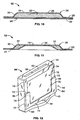
- FIG. 12 is a rear isometric view of a dispensing system similar to the one depicted in FIG. 3 with the addition of a slot on a sidewall thereof;
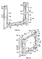
- FIG. 13 is an isometric view of a different holder.
- FIG. 14 is a rear isometric view of a dispensing system similar to the one depicted in FIG. 3 with the holder of FIG. 13 .
- the dispensing system 10 includes a volatile material dispenser 12, a refillable dispenser holder 14, and a display frame 16.
- the dispenser 12 is held within the display frame 16 and the dispenser holder 14:
- the dispenser 12 includes a blister 18, a peripheral flange 20, and an impermeable laminate 22 releasably adhered to the blister 18 and the flange 20.
- the blister 18 includes a non-porous permeable membrane 24 and a cup-shaped structure 26.
- the cup-shaped structure 26 includes a bottom wall 28 and four side walls 30 that in conjunction with the permeable membrane 24 acts as a sealed reservoir to contain a volatile material 32.
- the cup-shaped structure 26 is comprised of a recycled polyethylene terephthalate (RPET) layer adhesively bonded to a nylon laminate.
- the nylon laminate may also include a layer of ethylene vinyl acetate (EVA) coextruded to each side of a middle nylon layer.
- EVA ethylene vinyl acetate
- the nylon laminate and RPET layer of the cup-shaped structure 26 in one embodiment have a thickness of about 0.3 mm (0.012 in.) to about 0.4 mm (0.016 in.).
- the cup-shaped structure 26 is generally rectangular and/or square with overall dimensions of about 3 mm (0.118 in.) to about 5 mm (0.197 in.) high, about 50 mm (1.969 in.) to about 60 mm (2.362 in.) long, and about 50 mm (1.969 in.) to about 60 mm (2.362 in.) wide.
- Each cup-shaped structure 26 has four side walls 30.
- the corresponding side walls 30 each have a height of about 3 mm (0.118 in.) to about 5 mm (0.197 in.) and a width of about 50 mm (1.969 in.) to about 60 mm (2.362 in.).
- the side walls 30 taper slightly outward as one moves from the bottom wall 28 to the flange 20.
- the bottom wall 28 is also generally rectangular and has a length of about 48 mm (1.890 in.) to about 58 mm (2.283 in.) and a width of about 48 mm (1.890 in.) to about 58 mm (2.283 in.).
- the side walls 30 and the bottom wall 28 of the cup-like structure 26 in one embodiment are thermoformed from a single sheet of the RPET and nylon laminate that is heated, then blown and/or pressed into the flange-and-cup arrangement shown in FIG. 2 .
- the cup-shaped structure 26 may be clear and translucent, allowing for the visibility of the volatile material 32 contained within the blister 18. In an alternative embodiment, the cup-shaped structure 26 may be colored and translucent.
- the peripheral flange 20 is planar and is coupled to and extends outwardly from top edges of the cup-shaped structure 26. In one embodiment, the peripheral flange 20 extends outwardly from upper edges of the side walls 30.
- the flange 20 is integrally formed with the cup-shaped structure 26 in, for example, a thermoforming process, as described in the previous paragraph.
- the permeable membrane 24 has a thickness of about 0.05 mm (0.002 in.) to about 0.15 mm (0.006 in.) and has a density within a range of about 0.88 to 0.95 grams/cubic centimeter.
- the permeable membrane 24 may also be formed integrally with the impermeable laminate 22 and is heat fused to the flange 20 such that the permeable membrane 24 extends across the entire cup-shaped structure 26.
- FIGS. 8 and 10 show the permeable membrane 24 and the impermeable laminate 22 enclosing and sealing the cup 26 with the volatile material 32 stored inside, thereby forming a thin sealed container impermeable to the volatile material 32 stored inside.
- the permeable membrane 24 is comprised of low density polyethylene (LDPE) and is clear and translucent, allowing for visibility of the volatile material 32 contained within the blister 18.
- LDPE low density polyethylene
- the impermeable laminate 22 may include a layer of polypropylene, aluminum foil, and/or polyester.
- the polypropylene may be adhesively bonded to the aluminum foil layer, which may be adhesively bonded to the polyester layer.
- An extrusion bonding material may be used to bond the layers together.
- the impermeable laminate 22 has a thickness of between about 0.1 mm (0.004 in.) and about 0.2 mm (0.008 in.).
- the polyester layer is generally suitable for printing and may be the outer surface of the impermeable laminate 22.
- the impermeable laminate 22 may be attached to the blister 18 at the same time as the permeable membrane 24 if the impermeable laminate 22 and the permeable membrane 24 are co-extruded.
- the permeable membrane 24 and the impermeable laminate 22 may be attached to the flange 20 of the blister 18 using any conventional means, such as an adhesive, heat sealing, and/or crimping, or the like.
- the seal is substantially airtight so as to prevent leakage of air or the volatile material 32.
- the volatile material 32 does not completely fill the void within the blister 18.
- a relatively small amount of air can be tolerated in the dispenser 12 following the creation of the blister 18.
- the air in the sealed blister 18 is no more than about 3% to about 10% of the overall volume of the blister 18.
- the permeable membrane 24 is configured to distend and collapse with relatively few or no gas bubbles being formed.
- the impermeable laminate 22 covers the permeable membrane 24.
- the impermeable laminate 22 is removed from the blister 18 by a user grasping an end of the impermeable laminate 22 and peeling it off the blister 18.
- a tab 34, extension, or other means for grasping may be included as an extension of the impermeable laminate 22 to aid in removal of same.
- the extension may be at the corners, ends, and/or on the surface of the impermeable laminate 22.
- the dispensing system 10 begins to transition from a full or first condition ( FIGS. 8 and 10 ) to an empty or second condition ( FIG. 11 ). There may be a small amount of the volatile material 32 that remains in the blister 18 and the dispenser 12 will still be considered to have reached the second condition. As the volatile material 32 diffuses through the permeable membrane 24, the permeable membrane 24 slowly collapses upon the bottom wall 28. With reference to FIG. 11 , following diffusion of the volatile material 32 across the permeable membrane 24 there is less volatile material 32 contained within the dispenser 12. Substantially no new air enters the dispenser 12 subsequent to diffusion of the volatile material 32.
- the result of this is a pressure gradient across the permeable membrane 24, with a higher pressure existing in the ambient air than the pressure in the dispenser 12.
- the pressure gradient causes the ambient air to exert a net positive pressure upon the dispenser 12, which presses the permeable membrane 24 against the remaining volatile material 32 and ultimately the bottom wall 28.
- Continued diffusion of the volatile material 32 increases the force exerted upon the permeable membrane 24, which causes the remaining volatile material 32 to migrate from a center of the bottom wall 28 toward a periphery of the bottom wall 28.
- Continued migration and diffusion of the volatile material 32 results in an increasing surface area contact between the permeable membrane 24 and the bottom wall 28 until the dispenser 12 is empty, or nearly empty.
- the pressure gradient ultimately resulting in migration of the volatile material 32 may also be viewed as occurring due to an increasing compressed vacuum presence within the dispenser 12 as the volatile material 32 continues to diffuse across the permeable membrane 24.
- a small amount of the volatile material 32 may remain within the dispenser 12 when it is nearly empty.
- the volatile material 32 will typically be present in the form of a ring-like appearance (not shown) toward the periphery of the bottom wall 28.
- the pressure gradient between the ambient air and the interior of the dispenser 12 is reduced, thereby diminishing the tendency of the remaining volatile material 32 to form in a ring-like appearance.
- the concentration of certain thickening agents imparts a dry crystalline appearance to the remaining volatile material 32.
- a dye and a thickener combine to comprise approximately 1% to 3% of the overall volatile material 32 composition of the dispensing system 10 at the first condition.
- the dye and thickener combine to comprise approximately 2% of the overall volatile material 32 composition of the dispensing system 10 at the first condition.
- a higher composition of dye is present in the volatile material 32 when the dispenser 12 is nearly empty, as the dye utilized does not easily diffuse across the permeable membrane 24.
- the higher accumulation of dye results in a more readily viewable ring-like appearance.
- the color of the ring-like image is a more intense color than the coloration of the first condition because of the increased concentration of the dye material.
- the thickener and dye comprise nearly all of the material left within the dispenser 12. Of course, this may change dependent upon the particular dye composition and thickening agent utilized in the volatile material 32.
- the display frame 16 is a rectangular structure with four substantially equal-sized side walls 36 ( FIGS. 1 , 3 , 4 , and 5 ), a front face 38 ( FIGS. 4 and 5 ), and a rear face 40 ( FIGS. 1 and 3 ).
- the display frame 16 has a thickness within a range of about 12 mm (0.472 in.) to about 22 mm (0.866 in.) and a height and width within a range of about 70 mm (2.756 in.) to about 90 mm (3.543 in.).
- the display frame 16 has a thickness of about 16 mm (0.630 in.) and a height and width of about 86 mm (3.386 in.).
- the front face 38 of the display frame 16 in one embodiment has a surface area greater than or equal to about 3000 mm 2 .
- the front face 38 of the display frame 16 includes a recess 42.
- the recess 42 is defined by recessed ogee-shaped walls 44 and a square depression defined by four side walls 46 and a bottom wall 48.
- the recess 42 gives the display frame 16 the appearance of a picture frame surrounding and framing the bottom wall 48 of the recess 42.
- FIG. 8 which shows a cross sectional view of the dispensing system 10, shows the walls 44 and 46 defining the recess 42 with steps and curves in the manner of an ornate picture frame.
- the recess 42 is centered in the front face 38 and is disposed away from the side walls 36.
- the front face 38 appears as a border extending around the edges that define the recess 42, wherein the front face 38 has a constant width within a range of about 5 mm (0.197 in.) to about 20 mm (0.787 in.).
- the front face 38 may be planar and devoid of a recess.
- a single stepped recess is provided.
- a multiple stepped recess is provided.
- side walls defining the recesses may include curved and/or shaped walls.
- a raised rib may extend about an outer periphery of the front face 38 adjacent side walls 36 of the display frame 16.
- the rear face 40 of the display frame 16 includes a stepped recess 50 defined by stepped side walls and a square depression disposed therebetween.
- FIGS. 3 , 7, and 8 show that the stepped recess 50 is configured to completely receive the dispenser 12, with dispenser 12 positioned so that the permeable membrane 24 surface is substantially flush with the rear face 40.
- the stepped recess 50 includes a shallow peripheral recess 52 and a deep central recess 54.
- the central recess 54 is configured and dimensioned to receive the cup-shaped structure 26, and the peripheral recess 52 is configured and dimensioned to receive and support the flange 20.
- the central recess 54 and the peripheral recess 52 combined have a negative shape that is the same as that of the dispenser 12.
- the central recess 54 is deeper than the peripheral recess 52 since it accommodates the greater combined thickness of the cup-shaped structure 26, the flange 20, and the permeable membrane 24.
- the bottom wall 28 of the cup-shaped structure 26 is adjacent to and slightly spaced apart from a bottom 56 of the central recess 54.
- the central recess 54 and the peripheral recess 52 are centrally spaced from the edges of the rear face 40.
- the rear face 40 of the display frame 16 also includes a curved foot 58 disposed adjacent a lower side 60 of the display frame 16.
- the lower side 60 of the display frame 16 is defined by one of the side walls 36 that rests against a support surface.
- the curved foot 58 increases the stability of the display frame 16 to prevent same from tipping over. However, should the display frame 16 be tipped over, the curved foot 58 causes the permeable membrane 34 to be spaced from the support surface so that the potential for damage to the support surface by the volatile material 32 is minimized.
- the curved foot 58 extends outwardly from the rear face 40 about 4 mm (0.157 in.) to about 5 mm (0.197 in.) at its farthest point.
- An image 62 is disposed on the rear face 40 of the display frame 16.
- the image 62 is etched into a central portion of the bottom 56 of the central recess 54. While the present image is a tree, any graphical or textual image may be disposed on the rear face 40. Processes such as printing, forming, molding, etching, or silk screening may be used to place the image 62 onto the rear face 40.
- the image 62 may be positioned in any one a plurality of positions on the front face 38, the rear face 40, or the dispenser 12.
- the image 62 may be absent from the frame dispensing system 10.
- the display frame 16 may be constructed from a variety of compositions, including glass or an injection-molded plastic such as a copolyester resin.
- the display frame 16 is constructed from molded glass that is clear and transparent.
- the cup-like structure 26 is therefore viewable through the transparent front face 38.
- the cup-like structure 26 may be clear and translucent, allowing for the visibility of the volatile material 32 contained within the blister 18.
- at least one of the display frame 16 and the cup-like structure 26 is tinted.
- FIGS. 1 , 3 , and 6-9 depict a refill holder 64 for attachment to the rear face 40 of the display frame 16.
- the refill holder 64 comprises a U-shaped mounting member 66.
- the U-shaped mounting member 66 is attached to an outer periphery of the rear face 40 and includes a base member 68 that extends lengthwise across a lower portion 70 of the rear face 40.
- Side members 72 extend upwardly along the periphery of the rear face 40 from the base member 68.
- the side members 72 extend approximately one-half the distance between the lower portion 70 and an upper portion 74 of the rear face 40.
- the U-shaped mounting member 66 further includes an inwardly extending wall 76 attached thereto.
- the inwardly extending wall 76 forms a lip around the U-shaped mounting member 66.
- a channel 78 is formed in the space between the inwardly extending wall 76 and the rear face 40. More particularly, the channel 78 is formed in the space between the inwardly extending wall 76 and the portion of the rear face 40 defining the peripheral recess 52.
- the refill holder 64 is attached to the rear face 40 by an adhesive, however, any other type of securing means is considered within the scope of the present disclosure.
- the refill holder 64 allows the dispenser 12 to be removed from the display frame 16 and a replacement dispenser (not shown) to be placed into the display frame 16.
- the dispenser 12 of FIG. 3 is removed from the dispensing system 10 by grabbing a portion of the peripheral flange 20 adjacent the upper portion 74 of the display frame 16, or a side wall adjacent the upper portion 74, and pulling the dispenser 12 upwardly and outwardly from the refill holder 64.
- the channel 78 of the refill holder 64 is sized to be slightly larger than the thickness of the dispenser 12 in an unopened state, i.e., when the impermeable laminate 22 is still releasably adhered to the blister 18 and the flange 20.
- the extra space in the channel 78 therefore allows a user to pull or otherwise rotate an end of the dispenser 12 adjacent the upper portion 74 outwardly and away from the rear face 40 of the frame 16.
- Outward movement of the dispenser 12 allows a user to more easily grasp the peripheral flange 20 of the dispenser 12 as opposed to grasping the peripheral flange 20 when it is flush with the rear face 40 of the frame 16.
- the dispenser 12, or a replacement dispenser (not shown), is placed into the refill holder 64 by grasping an end of the dispenser 12 and orienting the cup-shaped structure 26 toward the rear face 40 of the frame 16.
- the dispenser 12 is slid downwardly into the channel 78 so that the peripheral flange 20 is disposed between the inwardly extending wall 76 and the shallow peripheral recess 52.
- cup-shaped structure 26 and the peripheral flange 20 are substantially flush with the deep and central recesses 54, 52, respectively, i.e, the cup-shaped structure 26 and the peripheral flange 20 may be completely flush with the portions of the rear face 40 defining the respective recesses 54, 52 or may be spaced wholly or partially therefrom.
- the refill holder 64 may also provide a similar benefit as the curved foot 58. Should the display frame 16 be tipped over, the refill holder 64 in combination with the curved foot 58 causes the permeable membrane 34 to be spaced from the support surface so that the potential for damage to the support surface by the volatile material 32 is minimized. In a different embodiment, the refill holder 64 provides the benefit of spacing the permeable membrane 34 from the support surface independent of the curved foot 58. In any of these embodiments, the sizing of the refill holder, i.e., the extent to which the refill holder 64 extends rearwardly from the rear face 40 of the display frame, will determine the effect the refill holder 64 has on minimizing contact between the support surface and the volatile material 32.
- the refill holder 64 is capable of being attached to any type of dispensing system, such as those disclosed in published U.S. Patent Application Nos. US 2006/0 000 922 , US 2006/0 000 923 and US 2006/0 002 102 , and published U.S. Patent Application US 2006/0 000 920 .
- US 2006/0 000 920 discloses a dispensing system similar to a dispensing system 80 depicted in FIG. 12 .
- the dispensing system 80 includes a slot 82 for receipt of a picture or other object to be held within the display frame 16 and viewed therethrough.
- the dispensing system 80 also includes the refill holder 64 for removing and replacing the dispenser 12.
- One skilled in the art will readily see how the dispensing systems disclosed in the present and above identified applications may be modified to provide for dispenser replaceable dispensing systems.
- the refill holder 64 may be made from a similar material as the display frame 16 or a dissimilar material.
- the refill holder 64 comprises a hardened plastic material.
- the refill holder 64 may also be colored or remain clear to provide certain aesthetic and functional characteristics.
- the refill holder 64 is transparent to allow a user to see through the refill holder 64 and provide a more pleasing appearance.
- the sizing of the refill holder 64 may be modified to allow the refill holder 64 to be placed onto variously sized frames or to provide for tighter or looser fits of the dispenser 12 within the refill holder 64, e.g., the spacing between the inwardly extending wall 76 and the shallow peripheral recess 52 may be modified or the side members 72 may be lengthened or shortened.
- FIGS. 13 and 14 depict a dispensing system 84 with a different refill holder 86 mounted onto the rear face 40 of the display frame 16.
- the refill holder 86 comprises opposing first and second side members 88, 90, respectively.
- Each of the first and second side members 88, 90 includes an outwardly extending mounting flange 92, 94, respectively, adhered or otherwise secured to the rear wall 40 of the display frame 16 adjacent a sidewall 36 thereof.
- First and second L-shaped brackets 96, 98 are integral with the mounting flanges 92, 94, respectively, and extend rearwardly therefrom.
- Each L-shaped bracket 96, 98 includes a rearwardly extending wall 100, 102 and an inwardly extending wall 104, 106, respectively.
- First and second tabs 108, 110 are integral with the L-shaped bracket 96 and extend inwardly therefrom toward the opposing side member 90.
- Third and fourth tabs 112, 114 are likewise integral with the L-shaped bracket 98 and extend inwardly therefrom toward the opposing side member 88.
- a first channel 116 is formed in a space between the first and second tabs 108, 110 and the inwardly extending wall 104 and a second channel 118 is formed in a space between the third and fourth tabs 112, 114 and the inwardly extending wall 106.
- a base member 120 is integral with the first and second side members 88, 90 and includes a shelf member 122 and an upwardly extending lip 124.
- the refill holder 86 allows the dispenser 12 to be removed from the frame 16 and a replacement dispenser (not shown) to be placed into the frame 16.
- the dispenser 12 of FIG. 14 is removed from the dispensing system 84 by grabbing a portion of the peripheral flange 20 of the dispenser 12 adjacent the upper portion 74 of the display frame 16 and pulling the dispenser 12 upwardly and outwardly from the refill holder 86.
- the dispenser 12, or a replacement dispenser is placed into the refill holder 86 by grasping an end of the dispenser 12 and orienting the cup-shaped structure 26 toward the rear face 40 of the frame 16.
- the dispenser 12 is slid downwardly into the first and second channels 116, 118 so that the peripheral flange 20 is disposed substantially rigidly therein.
- the dispenser 12 is fully disposed within the refill holder 86 when one side of the dispenser 12 contacts the shelf member 122 and is disposed between the upwardly extending lip 124 and the rear face 40. Further, when the dispenser 12 is fully disposed within the refill holder 86 the cup-shaped structure 26 does not substantially enter the stepped recess 50. Depending on the sizing of the various components comprising the refill holder 86, the cup-shaped structure 26 may not enter the stepped recess 50 at all.
- the refill holder 86 may be attached to any of the dispensing systems disclosed herein or modified accordingly to minimize contact between a support surface and the volatile material 32 when the display frame 16 is tipped over. Further, the refill holder 86 may be constructed of any of the materials and/or colored according to the disclosure herein. Still further, any modifications disclosed herein may similarly be made to the present refill holder 86. For example, the sizing of the refill holder 86 may be adjusted to accommodate variously sized dispensing systems, to provide a tighter or looser fit within the first and second channels 116, 118, to lengthen or shorten the first and second side members 88, 90, or to space the rear face 40 of the display frame 16 from a support surface should the display frame 16 tip over.
- Yet another non-exclusive modification of the refill holder 86 comprises the provision of differently shaped or positioned tabs 108, 110, 112, 114. Further, the number of tabs may be increased or decreased so as to have an equal or unequal number of tabs on opposing side members 88, 90.
- the volatile material dispensing system described herein advantageously provides a refillable fragrance dispenser.
- a user may easily replace a depleted fragrance dispenser as opposed to discarding the entire dispensing system.
Landscapes
- Life Sciences & Earth Sciences (AREA)
- Health & Medical Sciences (AREA)
- Pest Control & Pesticides (AREA)
- General Health & Medical Sciences (AREA)
- Epidemiology (AREA)
- Animal Behavior & Ethology (AREA)
- Public Health (AREA)
- Veterinary Medicine (AREA)
- Toxicology (AREA)
- Engineering & Computer Science (AREA)
- Insects & Arthropods (AREA)
- Wood Science & Technology (AREA)
- Zoology (AREA)
- Environmental Sciences (AREA)
- Disinfection, Sterilisation Or Deodorisation Of Air (AREA)
- Packaging Of Annular Or Rod-Shaped Articles, Wearing Apparel, Cassettes, Or The Like (AREA)
- Mirrors, Picture Frames, Photograph Stands, And Related Fastening Devices (AREA)
- Display Racks (AREA)
Abstract
Description
- The present invention generally relates to a volatile material dispensing system, and more particularly, to a refillable volatile material dispensing system.
- Volatile material dispensing systems have been used to provide fragrances to office or home settings. One such dispenser comprises a holder with a rectangular portion. Two opposing walls extend the length of the rectangular portion and depend from sides thereof. A ridge extends the length of the portion along a center thereof. Inwardly protruding - lips extend toward each other from ends of the opposing walls. The area enclosed by the portion, walls, and lips define a slot that can hold a solid material containing a fragrance.
- Another dispenser comprises a housing with a rectangular upper portion and a rounded lower portion. A rectangular channel is disposed within the rectangular upper portion. The channel is adapted to receive a solid perfume contained within a rectangular reservoir having a transparent permeable membrane covering one side thereof. A plug is disposed on a rear face of the housing to provide power to a heat conductor for volatizing the solid perfume, a lamp, and an optically sensitive element.
- Yet another dispenser comprises a scenting device adapted to function with a heating, air conditioning, or venting system. The device includes a first member that is rectangular in shape and made from an air permeable and relatively porous substance. A frame surrounds the periphery of the member and provides a rigid structure to assist in mounting the device. The device is inserted into a mounting means disposed adjacent an air filter. The mounting means comprises a U-shaped member having an inner groove for slidably receiving the frame therein.
Published US patent applicationUS2006/0000920 discloses a picture frame having front and rear faces. A recess is disposed within the rear face of the frame. A dispenser is disposed within the recess of the rear face, the dispenser including a reservoir and a vapor permeable membrane. A slot is disposed within a side wall of the frame that is configured to hold an image. - According to one embodiment of the present invention, a display frame with a refill holder comprises a transparent block having front and rear faces. A U-shaped mounting member is attached to the rear face about an outer periphery of same. The U-shaped mounting member has an inwardly extending wall. A channel is formed in a space between the rear face and the inwardly extending wall. A protrusion is attached to the rear face of the frame, wherein at least one of the protrusion and the inwardly extending wall are configured to distance the rear face from a support surface when the frame is in a substantially horizontal position and provide a substantially unimpeded air passage adjacent the rear face.
- According to another embodiment of the present invention, a volatile material dispensing system comprises a reservoir having a first surface and a vapor permeable membrane sealed to an outer periphery of the first surface. A volatile material is contained within the reservoir, wherein the volatile material is diffused through the membrane into an ambient atmosphere. A planar frame has a front face and a rear face, wherein the reservoir is releasably held within a reservoir holder disposed on the rear face of the frame. A protrusion is attached to the rear face of the frame, wherein at least one of the protrusion and the reservoir holder are configured to distance the membrane from a supporting surface when the frame is in a substantially horizontal position providing an air passage sufficient to impede volatile material gases from altering the supporting surface.
- A picture frame comprises a frame having front and rear faces. A recess is disposed within the rear face of the frame. A holder is disposed on the rear face of the frame. A dispenser is disposed within at least one of the recess of the rear face and the holder. The dispenser includes a reservoir and a vapor permeable membrane. A slot is disposed in a side wall of the frame and is configured to hold an image.
- Other aspects and advantages of the present invention will become apparent upon reading the following detailed description and upon reference to the drawings in which:
-
FIG. 1 is an exploded rear isometric view of the volatile material dispensing system that includes a frame, a holder, and a dispenser; -
FIG. 2 is an isometric view of the dispenser as shown inFIG. 1 ; -
FIG. 3 is a rear isometric view of the assembled dispensing system shown inFIG. 1 ; -
FIG. 4 is a front isometric view of the dispensing system ofFIG. 3 ; -
FIG. 5 is a front elevational view of the dispensing system ofFIG. 3 ; -
FIG. 6 is a side elevational view of the dispensing system ofFIG. 3 ; -
FIG. 7 is a plan view of the dispensing system ofFIG. 3 ; -
FIG. 8 is a sectional view of the dispensing system taken along the line 8-8 ofFIG. 5 ; -
FIG. 9 is an isometric view of the holder ofFIG. 1 ; -
FIG. 10 is a partial enlarged sectional view of the dispenser as shown inFIG. 8 in a filled condition; -
FIG. 11 is a partial enlarged sectional view of the dispenser as shown inFIG. 8 in an unfilled condition; -
FIG. 12 is a rear isometric view of a dispensing system similar to the one depicted inFIG. 3 with the addition of a slot on a sidewall thereof; -
FIG. 13 is an isometric view of a different holder; and -
FIG. 14 is a rear isometric view of a dispensing system similar to the one depicted inFIG. 3 with the holder ofFIG. 13 . - Referring to
FIGS. 1-11 , a volatilematerial dispensing system 10 is illustrated. Thedispensing system 10 includes avolatile material dispenser 12, arefillable dispenser holder 14, and adisplay frame 16. Thedispenser 12 is held within thedisplay frame 16 and the dispenser holder 14: - With particular reference to
FIGS. 1, 2 ,10, and 11 , thedispenser 12 includes ablister 18, aperipheral flange 20, and animpermeable laminate 22 releasably adhered to theblister 18 and theflange 20. Theblister 18 includes a non-porouspermeable membrane 24 and a cup-shaped structure 26. The cup-shaped structure 26 includes abottom wall 28 and fourside walls 30 that in conjunction with thepermeable membrane 24 acts as a sealed reservoir to contain avolatile material 32. - Illustratively, the cup-
shaped structure 26 is comprised of a recycled polyethylene terephthalate (RPET) layer adhesively bonded to a nylon laminate. The nylon laminate may also include a layer of ethylene vinyl acetate (EVA) coextruded to each side of a middle nylon layer. The nylon laminate and RPET layer of the cup-shapedstructure 26 in one embodiment have a thickness of about 0.3 mm (0.012 in.) to about 0.4 mm (0.016 in.). The cup-shapedstructure 26 is generally rectangular and/or square with overall dimensions of about 3 mm (0.118 in.) to about 5 mm (0.197 in.) high, about 50 mm (1.969 in.) to about 60 mm (2.362 in.) long, and about 50 mm (1.969 in.) to about 60 mm (2.362 in.) wide. Each cup-shapedstructure 26 has fourside walls 30. Thecorresponding side walls 30 each have a height of about 3 mm (0.118 in.) to about 5 mm (0.197 in.) and a width of about 50 mm (1.969 in.) to about 60 mm (2.362 in.). Theside walls 30 taper slightly outward as one moves from thebottom wall 28 to theflange 20. Thebottom wall 28 is also generally rectangular and has a length of about 48 mm (1.890 in.) to about 58 mm (2.283 in.) and a width of about 48 mm (1.890 in.) to about 58 mm (2.283 in.). Theside walls 30 and thebottom wall 28 of the cup-like structure 26 in one embodiment are thermoformed from a single sheet of the RPET and nylon laminate that is heated, then blown and/or pressed into the flange-and-cup arrangement shown inFIG. 2 . The cup-shapedstructure 26 may be clear and translucent, allowing for the visibility of thevolatile material 32 contained within theblister 18. In an alternative embodiment, the cup-shapedstructure 26 may be colored and translucent. - The
peripheral flange 20 is planar and is coupled to and extends outwardly from top edges of the cup-shapedstructure 26. In one embodiment, theperipheral flange 20 extends outwardly from upper edges of theside walls 30. Theflange 20 is integrally formed with the cup-shapedstructure 26 in, for example, a thermoforming process, as described in the previous paragraph. - Illustratively, the
permeable membrane 24 has a thickness of about 0.05 mm (0.002 in.) to about 0.15 mm (0.006 in.) and has a density within a range of about 0.88 to 0.95 grams/cubic centimeter. Thepermeable membrane 24 may also be formed integrally with theimpermeable laminate 22 and is heat fused to theflange 20 such that thepermeable membrane 24 extends across the entire cup-shapedstructure 26.FIGS. 8 and10 show thepermeable membrane 24 and theimpermeable laminate 22 enclosing and sealing thecup 26 with thevolatile material 32 stored inside, thereby forming a thin sealed container impermeable to thevolatile material 32 stored inside. This container remains substantially impermeable until the user grasps a corner of theimpermeable laminate 22 and peels theimpermeable laminate 22 from thepermeable membrane 24, thereby exposing thepermeable membrane 24 and permitting thevolatile material 32 to migrate through thepermeable membrane 24 and diffuse into the ambient air (FIG. 11 ). Thepermeable membrane 24 is comprised of low density polyethylene (LDPE) and is clear and translucent, allowing for visibility of thevolatile material 32 contained within theblister 18. - The
impermeable laminate 22 may include a layer of polypropylene, aluminum foil, and/or polyester. The polypropylene may be adhesively bonded to the aluminum foil layer, which may be adhesively bonded to the polyester layer. An extrusion bonding material may be used to bond the layers together. Illustratively, theimpermeable laminate 22 has a thickness of between about 0.1 mm (0.004 in.) and about 0.2 mm (0.008 in.). The polyester layer is generally suitable for printing and may be the outer surface of theimpermeable laminate 22. - Following placement of the
volatile material 32 into the cup-shapedstructure 26, a seal is made between theflange 20 and thepermeable membrane 24 thereby forming thedispenser 12. As noted above, theimpermeable laminate 22 may be attached to theblister 18 at the same time as thepermeable membrane 24 if theimpermeable laminate 22 and thepermeable membrane 24 are co-extruded. Thepermeable membrane 24 and theimpermeable laminate 22 may be attached to theflange 20 of theblister 18 using any conventional means, such as an adhesive, heat sealing, and/or crimping, or the like. The seal is substantially airtight so as to prevent leakage of air or thevolatile material 32. Thevolatile material 32 does not completely fill the void within theblister 18. A relatively small amount of air can be tolerated in thedispenser 12 following the creation of theblister 18. For example, the air in the sealedblister 18 is no more than about 3% to about 10% of the overall volume of theblister 18. As thevolatile material 32 diffuses out of thedispenser 12 little or no air enters theblister 18 through thepermeable membrane 24. In one embodiment, thepermeable membrane 24 is configured to distend and collapse with relatively few or no gas bubbles being formed. - There is substantially no diffusion of the
volatile material 32 when thedispenser 12 is filled and theimpermeable laminate 22 covers thepermeable membrane 24. Illustratively, theimpermeable laminate 22 is removed from theblister 18 by a user grasping an end of theimpermeable laminate 22 and peeling it off theblister 18. Atab 34, extension, or other means for grasping may be included as an extension of theimpermeable laminate 22 to aid in removal of same. The extension may be at the corners, ends, and/or on the surface of theimpermeable laminate 22. - Following removal of the
impermeable laminate 22, the dispensingsystem 10 begins to transition from a full or first condition (FIGS. 8 and10 ) to an empty or second condition (FIG. 11 ). There may be a small amount of thevolatile material 32 that remains in theblister 18 and thedispenser 12 will still be considered to have reached the second condition. As thevolatile material 32 diffuses through thepermeable membrane 24, thepermeable membrane 24 slowly collapses upon thebottom wall 28. With reference toFIG. 11 , following diffusion of thevolatile material 32 across thepermeable membrane 24 there is lessvolatile material 32 contained within thedispenser 12. Substantially no new air enters thedispenser 12 subsequent to diffusion of thevolatile material 32. The result of this is a pressure gradient across thepermeable membrane 24, with a higher pressure existing in the ambient air than the pressure in thedispenser 12. The pressure gradient causes the ambient air to exert a net positive pressure upon thedispenser 12, which presses thepermeable membrane 24 against the remainingvolatile material 32 and ultimately thebottom wall 28. Continued diffusion of thevolatile material 32 increases the force exerted upon thepermeable membrane 24, which causes the remainingvolatile material 32 to migrate from a center of thebottom wall 28 toward a periphery of thebottom wall 28. Continued migration and diffusion of thevolatile material 32 results in an increasing surface area contact between thepermeable membrane 24 and thebottom wall 28 until thedispenser 12 is empty, or nearly empty. The pressure gradient ultimately resulting in migration of thevolatile material 32 may also be viewed as occurring due to an increasing compressed vacuum presence within thedispenser 12 as thevolatile material 32 continues to diffuse across thepermeable membrane 24. - A small amount of the
volatile material 32 may remain within thedispenser 12 when it is nearly empty. Thevolatile material 32 will typically be present in the form of a ring-like appearance (not shown) toward the periphery of thebottom wall 28. However, in other embodiments the pressure gradient between the ambient air and the interior of thedispenser 12 is reduced, thereby diminishing the tendency of the remainingvolatile material 32 to form in a ring-like appearance. In yet other embodiments, the concentration of certain thickening agents imparts a dry crystalline appearance to the remainingvolatile material 32. In one embodiment, a dye and a thickener combine to comprise approximately 1% to 3% of the overallvolatile material 32 composition of the dispensingsystem 10 at the first condition. In a different embodiment, the dye and thickener combine to comprise approximately 2% of the overallvolatile material 32 composition of the dispensingsystem 10 at the first condition. A higher composition of dye is present in thevolatile material 32 when thedispenser 12 is nearly empty, as the dye utilized does not easily diffuse across thepermeable membrane 24. The higher accumulation of dye results in a more readily viewable ring-like appearance. The color of the ring-like image is a more intense color than the coloration of the first condition because of the increased concentration of the dye material. In the second condition the thickener and dye comprise nearly all of the material left within thedispenser 12. Of course, this may change dependent upon the particular dye composition and thickening agent utilized in thevolatile material 32. - The
display frame 16 is a rectangular structure with four substantially equal-sized side walls 36 (FIGS. 1 ,3 ,4 , and5 ), a front face 38 (FIGS. 4 and5 ), and a rear face 40 (FIGS. 1 and3 ). In one embodiment, thedisplay frame 16 has a thickness within a range of about 12 mm (0.472 in.) to about 22 mm (0.866 in.) and a height and width within a range of about 70 mm (2.756 in.) to about 90 mm (3.543 in.). In another embodiment, thedisplay frame 16 has a thickness of about 16 mm (0.630 in.) and a height and width of about 86 mm (3.386 in.). Thefront face 38 of thedisplay frame 16 in one embodiment has a surface area greater than or equal to about 3000 mm2. - The
front face 38 of thedisplay frame 16 includes arecess 42. Therecess 42 is defined by recessed ogee-shapedwalls 44 and a square depression defined by fourside walls 46 and abottom wall 48. Therecess 42 gives thedisplay frame 16 the appearance of a picture frame surrounding and framing thebottom wall 48 of therecess 42.FIG. 8 , which shows a cross sectional view of the dispensingsystem 10, shows thewalls recess 42 with steps and curves in the manner of an ornate picture frame. Therecess 42 is centered in thefront face 38 and is disposed away from theside walls 36. Thefront face 38 appears as a border extending around the edges that define therecess 42, wherein thefront face 38 has a constant width within a range of about 5 mm (0.197 in.) to about 20 mm (0.787 in.). In a different embodiment, thefront face 38 may be planar and devoid of a recess. In yet another embodiment, a single stepped recess is provided. In still another embodiment, a multiple stepped recess is provided. In any of the embodiments described herein, side walls defining the recesses may include curved and/or shaped walls. Further, in any of the embodiments described herein, a raised rib may extend about an outer periphery of thefront face 38adjacent side walls 36 of thedisplay frame 16. - The
rear face 40 of thedisplay frame 16 includes a steppedrecess 50 defined by stepped side walls and a square depression disposed therebetween.FIGS. 3 ,7, and 8 show that the steppedrecess 50 is configured to completely receive thedispenser 12, withdispenser 12 positioned so that thepermeable membrane 24 surface is substantially flush with therear face 40. The steppedrecess 50 includes a shallowperipheral recess 52 and a deepcentral recess 54. Thecentral recess 54 is configured and dimensioned to receive the cup-shapedstructure 26, and theperipheral recess 52 is configured and dimensioned to receive and support theflange 20. Thecentral recess 54 and theperipheral recess 52 combined have a negative shape that is the same as that of thedispenser 12. - As may be seen in
FIG. 8 , thecentral recess 54 is deeper than theperipheral recess 52 since it accommodates the greater combined thickness of the cup-shapedstructure 26, theflange 20, and thepermeable membrane 24. Thebottom wall 28 of the cup-shapedstructure 26 is adjacent to and slightly spaced apart from a bottom 56 of thecentral recess 54. Thecentral recess 54 and theperipheral recess 52 are centrally spaced from the edges of therear face 40. - The
rear face 40 of thedisplay frame 16 also includes acurved foot 58 disposed adjacent alower side 60 of thedisplay frame 16. Thelower side 60 of thedisplay frame 16 is defined by one of theside walls 36 that rests against a support surface. Thecurved foot 58 increases the stability of thedisplay frame 16 to prevent same from tipping over. However, should thedisplay frame 16 be tipped over, thecurved foot 58 causes thepermeable membrane 34 to be spaced from the support surface so that the potential for damage to the support surface by thevolatile material 32 is minimized. Thecurved foot 58 extends outwardly from therear face 40 about 4 mm (0.157 in.) to about 5 mm (0.197 in.) at its farthest point. - An
image 62 is disposed on therear face 40 of thedisplay frame 16. Theimage 62 is etched into a central portion of the bottom 56 of thecentral recess 54. While the present image is a tree, any graphical or textual image may be disposed on therear face 40. Processes such as printing, forming, molding, etching, or silk screening may be used to place theimage 62 onto therear face 40. In an alternative embodiment, theimage 62 may be positioned in any one a plurality of positions on thefront face 38, therear face 40, or thedispenser 12. In yet another embodiment, theimage 62 may be absent from theframe dispensing system 10. - The
display frame 16 may be constructed from a variety of compositions, including glass or an injection-molded plastic such as a copolyester resin. Illustratively, thedisplay frame 16 is constructed from molded glass that is clear and transparent. The cup-like structure 26 is therefore viewable through the transparentfront face 38. As noted above, the cup-like structure 26 may be clear and translucent, allowing for the visibility of thevolatile material 32 contained within theblister 18. In a different embodiment, at least one of thedisplay frame 16 and the cup-like structure 26 is tinted. -
FIGS. 1 ,3 , and6-9 depict arefill holder 64 for attachment to therear face 40 of thedisplay frame 16. Therefill holder 64 comprises a U-shaped mountingmember 66. The U-shaped mountingmember 66 is attached to an outer periphery of therear face 40 and includes abase member 68 that extends lengthwise across alower portion 70 of therear face 40.Side members 72 extend upwardly along the periphery of therear face 40 from thebase member 68. Theside members 72 extend approximately one-half the distance between thelower portion 70 and anupper portion 74 of therear face 40. The U-shaped mountingmember 66 further includes an inwardly extendingwall 76 attached thereto. The inwardly extendingwall 76 forms a lip around the U-shaped mountingmember 66. Achannel 78 is formed in the space between the inwardly extendingwall 76 and therear face 40. More particularly, thechannel 78 is formed in the space between the inwardly extendingwall 76 and the portion of therear face 40 defining theperipheral recess 52. Therefill holder 64 is attached to therear face 40 by an adhesive, however, any other type of securing means is considered within the scope of the present disclosure. - The
refill holder 64 allows thedispenser 12 to be removed from thedisplay frame 16 and a replacement dispenser (not shown) to be placed into thedisplay frame 16. By way of example, thedispenser 12 ofFIG. 3 is removed from the dispensingsystem 10 by grabbing a portion of theperipheral flange 20 adjacent theupper portion 74 of thedisplay frame 16, or a side wall adjacent theupper portion 74, and pulling thedispenser 12 upwardly and outwardly from therefill holder 64. Thechannel 78 of therefill holder 64 is sized to be slightly larger than the thickness of thedispenser 12 in an unopened state, i.e., when theimpermeable laminate 22 is still releasably adhered to theblister 18 and theflange 20. The extra space in thechannel 78 therefore allows a user to pull or otherwise rotate an end of thedispenser 12 adjacent theupper portion 74 outwardly and away from therear face 40 of theframe 16. Outward movement of thedispenser 12 allows a user to more easily grasp theperipheral flange 20 of thedispenser 12 as opposed to grasping theperipheral flange 20 when it is flush with therear face 40 of theframe 16. Thedispenser 12, or a replacement dispenser (not shown), is placed into therefill holder 64 by grasping an end of thedispenser 12 and orienting the cup-shapedstructure 26 toward therear face 40 of theframe 16. Thedispenser 12 is slid downwardly into thechannel 78 so that theperipheral flange 20 is disposed between the inwardly extendingwall 76 and the shallowperipheral recess 52. Further downward movement of theperipheral flange 20 within thechannel 78 forces the cup-shapedstructure 26 into the deepcentral recess 54 and theperipheral flange 20 into the shallowcentral recess 52. The cup-shapedstructure 26 and theperipheral flange 20 are substantially flush with the deep andcentral recesses structure 26 and theperipheral flange 20 may be completely flush with the portions of therear face 40 defining therespective recesses - The
refill holder 64 may also provide a similar benefit as thecurved foot 58. Should thedisplay frame 16 be tipped over, therefill holder 64 in combination with thecurved foot 58 causes thepermeable membrane 34 to be spaced from the support surface so that the potential for damage to the support surface by thevolatile material 32 is minimized. In a different embodiment, therefill holder 64 provides the benefit of spacing thepermeable membrane 34 from the support surface independent of thecurved foot 58. In any of these embodiments, the sizing of the refill holder, i.e., the extent to which therefill holder 64 extends rearwardly from therear face 40 of the display frame, will determine the effect therefill holder 64 has on minimizing contact between the support surface and thevolatile material 32. - The
refill holder 64 is capable of being attached to any type of dispensing system, such as those disclosed in published U.S. Patent Application Nos.US 2006/0 000 922 ,US 2006/0 000 923 andUS 2006/0 002 102 , and published U.S. Patent ApplicationUS 2006/0 000 920 . For example,US 2006/0 000 920 discloses a dispensing system similar to adispensing system 80 depicted inFIG. 12 . The dispensingsystem 80 includes aslot 82 for receipt of a picture or other object to be held within thedisplay frame 16 and viewed therethrough. The dispensingsystem 80 also includes therefill holder 64 for removing and replacing thedispenser 12. One skilled in the art will readily see how the dispensing systems disclosed in the present and above identified applications may be modified to provide for dispenser replaceable dispensing systems. - The
refill holder 64 may be made from a similar material as thedisplay frame 16 or a dissimilar material. In the present embodiment, therefill holder 64 comprises a hardened plastic material. Therefill holder 64 may also be colored or remain clear to provide certain aesthetic and functional characteristics. In the present embodiment, therefill holder 64 is transparent to allow a user to see through therefill holder 64 and provide a more pleasing appearance. Further, the sizing of therefill holder 64 may be modified to allow therefill holder 64 to be placed onto variously sized frames or to provide for tighter or looser fits of thedispenser 12 within therefill holder 64, e.g., the spacing between the inwardly extendingwall 76 and the shallowperipheral recess 52 may be modified or theside members 72 may be lengthened or shortened. -
FIGS. 13 and 14 depict adispensing system 84 with adifferent refill holder 86 mounted onto therear face 40 of thedisplay frame 16. Therefill holder 86 comprises opposing first andsecond side members second side members flange rear wall 40 of thedisplay frame 16 adjacent asidewall 36 thereof. First and second L-shapedbrackets flanges bracket rearwardly extending wall wall second tabs bracket 96 and extend inwardly therefrom toward the opposingside member 90. Third andfourth tabs bracket 98 and extend inwardly therefrom toward the opposingside member 88. Afirst channel 116 is formed in a space between the first andsecond tabs wall 104 and asecond channel 118 is formed in a space between the third andfourth tabs wall 106. Abase member 120 is integral with the first andsecond side members shelf member 122 and an upwardly extendinglip 124. - The
refill holder 86 allows thedispenser 12 to be removed from theframe 16 and a replacement dispenser (not shown) to be placed into theframe 16. By way of example, thedispenser 12 ofFIG. 14 is removed from the dispensingsystem 84 by grabbing a portion of theperipheral flange 20 of thedispenser 12 adjacent theupper portion 74 of thedisplay frame 16 and pulling thedispenser 12 upwardly and outwardly from therefill holder 86. Thedispenser 12, or a replacement dispenser (not shown), is placed into therefill holder 86 by grasping an end of thedispenser 12 and orienting the cup-shapedstructure 26 toward therear face 40 of theframe 16. Thedispenser 12 is slid downwardly into the first andsecond channels peripheral flange 20 is disposed substantially rigidly therein. Thedispenser 12 is fully disposed within therefill holder 86 when one side of thedispenser 12 contacts theshelf member 122 and is disposed between the upwardly extendinglip 124 and therear face 40. Further, when thedispenser 12 is fully disposed within therefill holder 86 the cup-shapedstructure 26 does not substantially enter the steppedrecess 50. Depending on the sizing of the various components comprising therefill holder 86, the cup-shapedstructure 26 may not enter the steppedrecess 50 at all. - The
refill holder 86 may be attached to any of the dispensing systems disclosed herein or modified accordingly to minimize contact between a support surface and thevolatile material 32 when thedisplay frame 16 is tipped over. Further, therefill holder 86 may be constructed of any of the materials and/or colored according to the disclosure herein. Still further, any modifications disclosed herein may similarly be made to thepresent refill holder 86. For example, the sizing of therefill holder 86 may be adjusted to accommodate variously sized dispensing systems, to provide a tighter or looser fit within the first andsecond channels second side members rear face 40 of thedisplay frame 16 from a support surface should thedisplay frame 16 tip over. Yet another non-exclusive modification of therefill holder 86 comprises the provision of differently shaped or positionedtabs side members - The volatile material dispensing system described herein advantageously provides a refillable fragrance dispenser. Thus, a user may easily replace a depleted fragrance dispenser as opposed to discarding the entire dispensing system.
- Numerous modifications will be apparent to those skilled in the art in view of the foregoing description. Accordingly, this description is to be construed as illustrative only and is presented for the purpose of enabling those skilled in the art to make and use the invention and to teach the best mode of carrying out same. The exclusive rights to all modifications which come within the scope of the appended claims are reserved.
Claims (11)
- A display frame (16), comprising:a transparent block having front and rear faces (38, 40):a protrusion (58) attached to the rear face (40) to distance the rear face (40) from a support surface when the frame (16) is in a substantially horizontal position and to provide a substantially unimpeded air passage adjacent the rear face;said rear face (40) having an upper portion (74) and a lower portion (70) separated by a stepped recess disposed within the rear face (40), the stepped recess including a shallow peripheral recess (52) and a deep central recess (54); anda fragrance dispenser (12) comprising a blister (18) and a peripheral flange (20) extending thereabout,characterized in that the display frame (16) comprises a refill holder (14, 64) comprising a U-shaped mounting member (66) attached to the rear face (40) about an outer periphery of same, the U-shaped mounting member (66) having an inwardly extending wall (76), wherein a channel (78) is formed in a space between a portion of the rear face (40) defining the peripheral recess (52) and the inwardly extending wall (76);wherein the U-shaped mounting member consists of a base member (68) and side arm portions (72), the side arm portions (72) extending approximately one half the distance between the lower portion (70) and the upper portion (74) of the rear face (40);the fragrance dispenser (12) being replaceably insertable into the U-shaped mounting member (66) such that the fragrance dispenser can be removed by grabbing a portion of the peripheral flange (20) adjacent the upper portion (74) of the display frame and pulling the fragrance dispenser (12) upwardly and outwardly from the channel (78), and a replacement dispenser can be placed in the mounting member (66) by grasping an end of the dispenser (12) and orienting the blister (18) towards the rear face of the frame and then sliding the dispenser (12) downwardly into the channel (78) so that the peripheral flange (20) is disposed between the inwardly extending wall (76) and the shallow peripheral recess (52) and then moving the dispenser further downwards within the channel (78) to force the blister (18) into the deep central recess (54) and the peripheral flange (20) into the shallow central recess (52).
- The display frame of claim 1, wherein the peripheral flange (20) is held within the channel (78) so that the peripheral flange (20) is substantially flush with a portion of the rear face (40) defining the peripheral recess (52) and a bottom end of the blister (18) is substantially flush with a portion of the rear face (40) defining the central recess (54).
- The display frame of claim 1, wherein at least one of the U-shaped mounting member (66) and the inwardly extending wall (78) comprises a transparent material.
- The display frame of claim 1, wherein the U-shaped mounting member (66) and the inwardly extending wall (78) are comprised of a different material than the display frame (16).
- A volatile material dispensing system, comprising:a reservoir (12) having a first surface and a vapor permeable membrane (24) sealed to an outer periphery of the first surface;a volatile material (32) contained within the reservoir (12), wherein the volatile material (32) is diffused through the membrane (24) into an ambient atmosphere;a planar frame (16) having a front face (38) and a rear face (40), wherein the reservoir (12) is releasably held within a reservoir holder disposed on the rear face (40) of the frame; anda protrusion (58) attached to the rear face of the frame, wherein at least one of the protrusion (58) and the reservoir holder (14) are configured to distance the membrane (24) from a supporting surface when the frame is in a substantially horizontal position providing an air passage sufficient to impede volatile material gases from altering the supporting surface;characterized in that the reservoir holder (14) comprises opposing first and second side members (88,90) secured to the rear face (40) adjacent side walls of the frame (16) and a base member (120) extending between the first and second side members (88, 90) adjacent a lower portion of the frame (16);wherein each of the first and second side members (88, 90) includes a mounting flange (92, 94) secured to the rear face (40) of the frame, an L-shaped bracket (96, 98) having walls that extend rearwardly and inwardly from the mounting flange (92, 94), and at least one tab (108, 110, 112, 114) extending inwardly from the L-shaped bracket (96, 98); andeach of the first and second side members (88, 90) includes a channel (116, 118) formed in a space between the inwardly extending wall (104, 106) of the L-shaped bracket (96, 98) and the at least one tab (108, 110, 112, 114), wherein the channel (116, 118) is adapted to allow the outer periphery (20) of the first surface of the reservoir (18) to fit therein.
- The system of claim 5, wherein the reservoir holder (14) comprises a mounting member (66) extending about a periphery of the rear face (40) and an inwardly directed lip (78) extending from the mounting member (66).
- The system of claim 6, wherein a channel (78) is formed in the space between the lip (78) and the rear face (40) of the frame (16), the channel (78) being adapted to allow the outer periphery of the first surface of the reservoir to fit therein.
- The system of claim 5, wherein the rear face (40) of the frame (16) includes a stepped recess (52, 54) having an inner (54) and an outer recess (52).
- The system of claim 8, wherein the inner recess (54) is deeper than the outer recess (52), and wherein the inner recess (54) and the outer recess (52) are adapted to hold a cup-like structure (26) of the reservoir (12) and the outer periphery (20) of the first surface of the reservoir (12), respectively.
- The system according to claim 5, wherein the system further comprises a removable vapor impermeable laminate (22) covering the vapor permeable membrane (24) to prevent diffusion of the volatile material (32).
- The system according to claim 5, wherein the volatile material (32) comprises at least one of an air freshener, fragrance, insecticide, insect repellent, odor eliminator, aroma-therapeutic material, sanitizer, an mold or mildew inhibitor.
Applications Claiming Priority (2)
| Application Number | Priority Date | Filing Date | Title |
|---|---|---|---|
| US11/337,277 US7426799B2 (en) | 2004-06-30 | 2006-01-23 | Air freshener with frame and refill holder |
| PCT/US2007/001568 WO2007087238A1 (en) | 2006-01-23 | 2007-01-22 | Air freshener with frame and refill holder |
Publications (2)
| Publication Number | Publication Date |
|---|---|
| EP1979009A1 EP1979009A1 (en) | 2008-10-15 |
| EP1979009B1 true EP1979009B1 (en) | 2011-10-26 |
Family
ID=38121936
Family Applications (1)
| Application Number | Title | Priority Date | Filing Date |
|---|---|---|---|
| EP07762414A Not-in-force EP1979009B1 (en) | 2006-01-23 | 2007-01-22 | Air freshener with frame and refill holder |
Country Status (11)
| Country | Link |
|---|---|
| EP (1) | EP1979009B1 (en) |
| JP (1) | JP2009523676A (en) |
| KR (1) | KR101294095B1 (en) |
| CN (1) | CN101400376B (en) |
| AT (1) | ATE530202T1 (en) |
| AU (1) | AU2007208412B2 (en) |
| BR (1) | BRPI0706717B1 (en) |
| CA (1) | CA2637723C (en) |
| ES (1) | ES2376007T3 (en) |
| MX (1) | MX2008009472A (en) |
| WO (1) | WO2007087238A1 (en) |
Cited By (2)
| Publication number | Priority date | Publication date | Assignee | Title |
|---|---|---|---|---|
| US11944096B2 (en) | 2019-12-06 | 2024-04-02 | S.C. Johnson & Son, Inc. | Dispenser and method of use thereof |
| WO2026029953A1 (en) * | 2024-07-30 | 2026-02-05 | The Procter & Gamble Company | Cartridge for delivering a volatile material |
Families Citing this family (8)
| Publication number | Priority date | Publication date | Assignee | Title |
|---|---|---|---|---|
| ES2564564T3 (en) * | 2007-11-26 | 2016-03-23 | S.C. Johnson & Son, Inc. | Volatile material dispensing system |
| JP2013537441A (en) * | 2010-07-12 | 2013-10-03 | エス.シー. ジョンソン アンド サン、インコーポレイテッド | Air fresh system |
| JP2013039112A (en) * | 2011-08-19 | 2013-02-28 | Dainippon Jochugiku Co Ltd | Agent-volatilizing material |
| US9278151B2 (en) * | 2012-11-27 | 2016-03-08 | S.C. Johnson & Son, Inc. | Volatile material dispenser |
| US9327043B2 (en) * | 2013-01-25 | 2016-05-03 | The Procter & Gamble Company | Device for delivering a volatile fluid to the atmosphere |
| US9327044B2 (en) * | 2013-01-25 | 2016-05-03 | The Procter & Gamble Company | Method for delivering a volatile fluid to the atmosphere |
| JP7319176B2 (en) * | 2019-11-14 | 2023-08-01 | エステー株式会社 | chemical volatilizer |
| JP7565863B2 (en) * | 2021-05-25 | 2024-10-11 | エステー株式会社 | Medicine container and medicine volatilizer |
Family Cites Families (14)
| Publication number | Priority date | Publication date | Assignee | Title |
|---|---|---|---|---|
| US3541045A (en) * | 1968-03-07 | 1970-11-17 | Hercules Inc | Coating composition |
| US3540146A (en) * | 1968-06-11 | 1970-11-17 | Robert M Watkins | Easel-back frame and adaptor therefor |
| JPS58190200U (en) * | 1982-06-10 | 1983-12-17 | 島田 高義 | decorative panels |
| JPH0335183Y2 (en) * | 1987-10-24 | 1991-07-25 | ||
| US5148984A (en) * | 1991-03-14 | 1992-09-22 | Vaportek, Inc. | Device for dispensing a vaporizable material |
| US5361522A (en) * | 1994-01-28 | 1994-11-08 | Green Dennis E | Air freshener picture frame |
| US5647052A (en) * | 1995-04-28 | 1997-07-08 | Reckitt & Colman Inc. | Volatile substance dispenser and method of dispensing a volatile substance with dissipation indication |
| US5556192A (en) * | 1995-07-18 | 1996-09-17 | Yeti Shine Co., Ltd. | Perfumer structure with an optically controlled night lamp |
| US5735460A (en) * | 1995-09-05 | 1998-04-07 | United Industrial Trading Corp. | Air freshener housing cover |
| US5950922A (en) * | 1996-09-13 | 1999-09-14 | Flinn; Gregory | Holder for an air freshener |
| JPH10263068A (en) * | 1997-03-25 | 1998-10-06 | Sekisui Chem Co Ltd | Picture frame type air freshener container |
| US7188780B2 (en) * | 2004-06-30 | 2007-03-13 | S.C. Johnson & Son, Inc. | Volatile material expiration indicating system |
| US7607250B2 (en) * | 2004-06-30 | 2009-10-27 | S.C. Johnson & Son, Inc. | Air freshener with picture frame |
| US7213770B2 (en) * | 2004-06-30 | 2007-05-08 | S. C. Johnson & Son, Inc. | Volatile material dispensing system |
-
2007
- 2007-01-22 CN CN2007800084734A patent/CN101400376B/en not_active Expired - Fee Related
- 2007-01-22 MX MX2008009472A patent/MX2008009472A/en active IP Right Grant
- 2007-01-22 AT AT07762414T patent/ATE530202T1/en not_active IP Right Cessation
- 2007-01-22 KR KR1020087018155A patent/KR101294095B1/en not_active Expired - Fee Related
- 2007-01-22 CA CA2637723A patent/CA2637723C/en not_active Expired - Fee Related
- 2007-01-22 EP EP07762414A patent/EP1979009B1/en not_active Not-in-force
- 2007-01-22 BR BRPI0706717A patent/BRPI0706717B1/en not_active IP Right Cessation
- 2007-01-22 ES ES07762414T patent/ES2376007T3/en active Active
- 2007-01-22 WO PCT/US2007/001568 patent/WO2007087238A1/en not_active Ceased
- 2007-01-22 AU AU2007208412A patent/AU2007208412B2/en not_active Ceased
- 2007-01-22 JP JP2008552339A patent/JP2009523676A/en active Pending
Cited By (3)
| Publication number | Priority date | Publication date | Assignee | Title |
|---|---|---|---|---|
| US11944096B2 (en) | 2019-12-06 | 2024-04-02 | S.C. Johnson & Son, Inc. | Dispenser and method of use thereof |
| US12274262B2 (en) | 2019-12-06 | 2025-04-15 | S. C. Johnson & Son, Inc. | Dispenser and method of use thereof |
| WO2026029953A1 (en) * | 2024-07-30 | 2026-02-05 | The Procter & Gamble Company | Cartridge for delivering a volatile material |
Also Published As
| Publication number | Publication date |
|---|---|
| KR101294095B1 (en) | 2013-08-08 |
| EP1979009A1 (en) | 2008-10-15 |
| AU2007208412B2 (en) | 2012-09-20 |
| CA2637723C (en) | 2011-05-24 |
| KR20080106167A (en) | 2008-12-04 |
| BRPI0706717B1 (en) | 2016-04-19 |
| WO2007087238A1 (en) | 2007-08-02 |
| AU2007208412A1 (en) | 2007-08-02 |
| MX2008009472A (en) | 2008-09-23 |
| ATE530202T1 (en) | 2011-11-15 |
| CA2637723A1 (en) | 2007-08-02 |
| CN101400376B (en) | 2013-04-10 |
| ES2376007T3 (en) | 2012-03-08 |
| JP2009523676A (en) | 2009-06-25 |
| BRPI0706717A2 (en) | 2011-04-05 |
| CN101400376A (en) | 2009-04-01 |
Similar Documents
| Publication | Publication Date | Title |
|---|---|---|
| US7426799B2 (en) | Air freshener with frame and refill holder | |
| EP1979009B1 (en) | Air freshener with frame and refill holder | |
| US7607250B2 (en) | Air freshener with picture frame | |
| US7441360B2 (en) | Air freshener with picture frame | |
| EP1778302B1 (en) | Volatile material dispensing system | |
| US7188780B2 (en) | Volatile material expiration indicating system | |
| US11077221B2 (en) | Volatile dispenser for use in volatile dispensing systems | |
| TWI379262B (en) | Air freshener with frame and refill holder |
Legal Events
| Date | Code | Title | Description |
|---|---|---|---|
| PUAI | Public reference made under article 153(3) epc to a published international application that has entered the european phase |
Free format text: ORIGINAL CODE: 0009012 |
|
| 17P | Request for examination filed |
Effective date: 20080805 |
|
| AK | Designated contracting states |
Kind code of ref document: A1 Designated state(s): AT BE BG CH CY CZ DE DK EE ES FI FR GB GR HU IE IS IT LI LT LU LV MC NL PL PT RO SE SI SK TR |
|
| 17Q | First examination report despatched |
Effective date: 20110207 |
|
| GRAP | Despatch of communication of intention to grant a patent |
Free format text: ORIGINAL CODE: EPIDOSNIGR1 |
|
| DAX | Request for extension of the european patent (deleted) | ||
| GRAS | Grant fee paid |
Free format text: ORIGINAL CODE: EPIDOSNIGR3 |
|
| GRAA | (expected) grant |
Free format text: ORIGINAL CODE: 0009210 |
|
| AK | Designated contracting states |
Kind code of ref document: B1 Designated state(s): AT BE BG CH CY CZ DE DK EE ES FI FR GB GR HU IE IS IT LI LT LU LV MC NL PL PT RO SE SI SK TR |
|
| REG | Reference to a national code |
Ref country code: GB Ref legal event code: FG4D |
|
| REG | Reference to a national code |
Ref country code: CH Ref legal event code: EP |
|
| REG | Reference to a national code |
Ref country code: IE Ref legal event code: FG4D |
|
| REG | Reference to a national code |
Ref country code: DE Ref legal event code: R096 Ref document number: 602007018264 Country of ref document: DE Effective date: 20120126 |
|
| REG | Reference to a national code |
Ref country code: NL Ref legal event code: VDEP Effective date: 20111026 |
|
| REG | Reference to a national code |
Ref country code: ES Ref legal event code: FG2A Ref document number: 2376007 Country of ref document: ES Kind code of ref document: T3 Effective date: 20120308 |
|
| LTIE | Lt: invalidation of european patent or patent extension |
Effective date: 20111026 |
|
| REG | Reference to a national code |
Ref country code: AT Ref legal event code: MK05 Ref document number: 530202 Country of ref document: AT Kind code of ref document: T Effective date: 20111026 |
|
| PG25 | Lapsed in a contracting state [announced via postgrant information from national office to epo] |
Ref country code: BE Free format text: LAPSE BECAUSE OF FAILURE TO SUBMIT A TRANSLATION OF THE DESCRIPTION OR TO PAY THE FEE WITHIN THE PRESCRIBED TIME-LIMIT Effective date: 20111026 Ref country code: LT Free format text: LAPSE BECAUSE OF FAILURE TO SUBMIT A TRANSLATION OF THE DESCRIPTION OR TO PAY THE FEE WITHIN THE PRESCRIBED TIME-LIMIT Effective date: 20111026 Ref country code: IS Free format text: LAPSE BECAUSE OF FAILURE TO SUBMIT A TRANSLATION OF THE DESCRIPTION OR TO PAY THE FEE WITHIN THE PRESCRIBED TIME-LIMIT Effective date: 20120226 |
|
| PG25 | Lapsed in a contracting state [announced via postgrant information from national office to epo] |
Ref country code: LV Free format text: LAPSE BECAUSE OF FAILURE TO SUBMIT A TRANSLATION OF THE DESCRIPTION OR TO PAY THE FEE WITHIN THE PRESCRIBED TIME-LIMIT Effective date: 20111026 Ref country code: GR Free format text: LAPSE BECAUSE OF FAILURE TO SUBMIT A TRANSLATION OF THE DESCRIPTION OR TO PAY THE FEE WITHIN THE PRESCRIBED TIME-LIMIT Effective date: 20120127 Ref country code: SE Free format text: LAPSE BECAUSE OF FAILURE TO SUBMIT A TRANSLATION OF THE DESCRIPTION OR TO PAY THE FEE WITHIN THE PRESCRIBED TIME-LIMIT Effective date: 20111026 Ref country code: PL Free format text: LAPSE BECAUSE OF FAILURE TO SUBMIT A TRANSLATION OF THE DESCRIPTION OR TO PAY THE FEE WITHIN THE PRESCRIBED TIME-LIMIT Effective date: 20111026 Ref country code: NL Free format text: LAPSE BECAUSE OF FAILURE TO SUBMIT A TRANSLATION OF THE DESCRIPTION OR TO PAY THE FEE WITHIN THE PRESCRIBED TIME-LIMIT Effective date: 20111026 Ref country code: SI Free format text: LAPSE BECAUSE OF FAILURE TO SUBMIT A TRANSLATION OF THE DESCRIPTION OR TO PAY THE FEE WITHIN THE PRESCRIBED TIME-LIMIT Effective date: 20111026 Ref country code: PT Free format text: LAPSE BECAUSE OF FAILURE TO SUBMIT A TRANSLATION OF THE DESCRIPTION OR TO PAY THE FEE WITHIN THE PRESCRIBED TIME-LIMIT Effective date: 20120227 |
|
| PG25 | Lapsed in a contracting state [announced via postgrant information from national office to epo] |
Ref country code: CY Free format text: LAPSE BECAUSE OF FAILURE TO SUBMIT A TRANSLATION OF THE DESCRIPTION OR TO PAY THE FEE WITHIN THE PRESCRIBED TIME-LIMIT Effective date: 20111026 |
|
| PG25 | Lapsed in a contracting state [announced via postgrant information from national office to epo] |
Ref country code: BG Free format text: LAPSE BECAUSE OF FAILURE TO SUBMIT A TRANSLATION OF THE DESCRIPTION OR TO PAY THE FEE WITHIN THE PRESCRIBED TIME-LIMIT Effective date: 20120126 Ref country code: DK Free format text: LAPSE BECAUSE OF FAILURE TO SUBMIT A TRANSLATION OF THE DESCRIPTION OR TO PAY THE FEE WITHIN THE PRESCRIBED TIME-LIMIT Effective date: 20111026 Ref country code: SK Free format text: LAPSE BECAUSE OF FAILURE TO SUBMIT A TRANSLATION OF THE DESCRIPTION OR TO PAY THE FEE WITHIN THE PRESCRIBED TIME-LIMIT Effective date: 20111026 Ref country code: EE Free format text: LAPSE BECAUSE OF FAILURE TO SUBMIT A TRANSLATION OF THE DESCRIPTION OR TO PAY THE FEE WITHIN THE PRESCRIBED TIME-LIMIT Effective date: 20111026 Ref country code: CZ Free format text: LAPSE BECAUSE OF FAILURE TO SUBMIT A TRANSLATION OF THE DESCRIPTION OR TO PAY THE FEE WITHIN THE PRESCRIBED TIME-LIMIT Effective date: 20111026 |
|
| PG25 | Lapsed in a contracting state [announced via postgrant information from national office to epo] |
Ref country code: MC Free format text: LAPSE BECAUSE OF NON-PAYMENT OF DUE FEES Effective date: 20120131 Ref country code: RO Free format text: LAPSE BECAUSE OF FAILURE TO SUBMIT A TRANSLATION OF THE DESCRIPTION OR TO PAY THE FEE WITHIN THE PRESCRIBED TIME-LIMIT Effective date: 20111026 |
|
| PLBE | No opposition filed within time limit |
Free format text: ORIGINAL CODE: 0009261 |
|
| REG | Reference to a national code |
Ref country code: CH Ref legal event code: PL |
|
| STAA | Information on the status of an ep patent application or granted ep patent |
Free format text: STATUS: NO OPPOSITION FILED WITHIN TIME LIMIT |
|
| 26N | No opposition filed |
Effective date: 20120727 |
|
| REG | Reference to a national code |
Ref country code: FR Ref legal event code: ST Effective date: 20120928 |
|
| REG | Reference to a national code |
Ref country code: IE Ref legal event code: MM4A |
|
| PG25 | Lapsed in a contracting state [announced via postgrant information from national office to epo] |
Ref country code: LI Free format text: LAPSE BECAUSE OF NON-PAYMENT OF DUE FEES Effective date: 20120131 Ref country code: CH Free format text: LAPSE BECAUSE OF NON-PAYMENT OF DUE FEES Effective date: 20120131 |
|
| REG | Reference to a national code |
Ref country code: DE Ref legal event code: R097 Ref document number: 602007018264 Country of ref document: DE Effective date: 20120727 |
|
| PG25 | Lapsed in a contracting state [announced via postgrant information from national office to epo] |
Ref country code: FR Free format text: LAPSE BECAUSE OF NON-PAYMENT OF DUE FEES Effective date: 20120131 |
|
| PG25 | Lapsed in a contracting state [announced via postgrant information from national office to epo] |
Ref country code: AT Free format text: LAPSE BECAUSE OF FAILURE TO SUBMIT A TRANSLATION OF THE DESCRIPTION OR TO PAY THE FEE WITHIN THE PRESCRIBED TIME-LIMIT Effective date: 20111026 Ref country code: IE Free format text: LAPSE BECAUSE OF NON-PAYMENT OF DUE FEES Effective date: 20120122 |
|
| PG25 | Lapsed in a contracting state [announced via postgrant information from national office to epo] |
Ref country code: FI Free format text: LAPSE BECAUSE OF FAILURE TO SUBMIT A TRANSLATION OF THE DESCRIPTION OR TO PAY THE FEE WITHIN THE PRESCRIBED TIME-LIMIT Effective date: 20111026 |
|
| PG25 | Lapsed in a contracting state [announced via postgrant information from national office to epo] |
Ref country code: TR Free format text: LAPSE BECAUSE OF FAILURE TO SUBMIT A TRANSLATION OF THE DESCRIPTION OR TO PAY THE FEE WITHIN THE PRESCRIBED TIME-LIMIT Effective date: 20111026 |
|
| PG25 | Lapsed in a contracting state [announced via postgrant information from national office to epo] |
Ref country code: LU Free format text: LAPSE BECAUSE OF NON-PAYMENT OF DUE FEES Effective date: 20120122 |
|
| PG25 | Lapsed in a contracting state [announced via postgrant information from national office to epo] |
Ref country code: HU Free format text: LAPSE BECAUSE OF FAILURE TO SUBMIT A TRANSLATION OF THE DESCRIPTION OR TO PAY THE FEE WITHIN THE PRESCRIBED TIME-LIMIT Effective date: 20070122 |
|
| PGFP | Annual fee paid to national office [announced via postgrant information from national office to epo] |
Ref country code: GB Payment date: 20181219 Year of fee payment: 13 |
|
| PGFP | Annual fee paid to national office [announced via postgrant information from national office to epo] |
Ref country code: IT Payment date: 20190102 Year of fee payment: 13 Ref country code: ES Payment date: 20190201 Year of fee payment: 13 Ref country code: DE Payment date: 20181218 Year of fee payment: 13 |
|
| REG | Reference to a national code |
Ref country code: DE Ref legal event code: R119 Ref document number: 602007018264 Country of ref document: DE |
|
| GBPC | Gb: european patent ceased through non-payment of renewal fee |
Effective date: 20200122 |
|
| PG25 | Lapsed in a contracting state [announced via postgrant information from national office to epo] |
Ref country code: DE Free format text: LAPSE BECAUSE OF NON-PAYMENT OF DUE FEES Effective date: 20200801 Ref country code: GB Free format text: LAPSE BECAUSE OF NON-PAYMENT OF DUE FEES Effective date: 20200122 |
|
| PG25 | Lapsed in a contracting state [announced via postgrant information from national office to epo] |
Ref country code: IT Free format text: LAPSE BECAUSE OF NON-PAYMENT OF DUE FEES Effective date: 20200122 |
|
| REG | Reference to a national code |
Ref country code: ES Ref legal event code: FD2A Effective date: 20210604 |
|
| PG25 | Lapsed in a contracting state [announced via postgrant information from national office to epo] |
Ref country code: ES Free format text: LAPSE BECAUSE OF NON-PAYMENT OF DUE FEES Effective date: 20200123 |