EP1935505A1 - Piezoelectric spraying system and corresponding refill - Google Patents
Piezoelectric spraying system and corresponding refill Download PDFInfo
- Publication number
- EP1935505A1 EP1935505A1 EP07123600A EP07123600A EP1935505A1 EP 1935505 A1 EP1935505 A1 EP 1935505A1 EP 07123600 A EP07123600 A EP 07123600A EP 07123600 A EP07123600 A EP 07123600A EP 1935505 A1 EP1935505 A1 EP 1935505A1
- Authority
- EP
- European Patent Office
- Prior art keywords
- piezoelectric
- refill
- product
- housing
- spraying
- Prior art date
- Legal status (The legal status is an assumption and is not a legal conclusion. Google has not performed a legal analysis and makes no representation as to the accuracy of the status listed.)
- Granted
Links
Images


Classifications
-
- B—PERFORMING OPERATIONS; TRANSPORTING
- B05—SPRAYING OR ATOMISING IN GENERAL; APPLYING FLUENT MATERIALS TO SURFACES, IN GENERAL
- B05B—SPRAYING APPARATUS; ATOMISING APPARATUS; NOZZLES
- B05B17/00—Apparatus for spraying or atomising liquids or other fluent materials, not covered by the preceding groups
- B05B17/04—Apparatus for spraying or atomising liquids or other fluent materials, not covered by the preceding groups operating with special methods
- B05B17/06—Apparatus for spraying or atomising liquids or other fluent materials, not covered by the preceding groups operating with special methods using ultrasonic or other kinds of vibrations
- B05B17/0607—Apparatus for spraying or atomising liquids or other fluent materials, not covered by the preceding groups operating with special methods using ultrasonic or other kinds of vibrations generated by electrical means, e.g. piezoelectric transducers
- B05B17/0653—Details
- B05B17/0676—Feeding means
Definitions
- the present invention relates to a piezoelectric sputtering system and a refill for such a system.
- Piezoelectric spraying devices are widely used for spraying low viscosity liquids, for example room fragrances.
- a wick allows to supply, by capillarity, a membrane vibrated by a ceramic.
- the invention aims in particular to provide a spraying system for spraying products having different rheologies and formulations, polarizable or not.
- the invention allows the user to spray a product, depending on the selected refill.
- the piezoelectric sputtering device may comprise a membrane to be vibrated, carried by the removable refill, and a piezoelectric element for vibrating the membrane.
- This piezoelectric element which comprises for example a ceramic, makes it possible to transform an excitation voltage into a vibration.
- the piezoelectric element can also be carried by the refill and bound to the membrane. Alternatively, the piezoelectric element may be carried by the housing.
- the removable refill may be devoid of piezoelectric element.
- the piezoelectric spraying device can be worn only by the removable refill.
- piezoelectric device can make it possible to spray with a relatively wide spray, if necessary, whether the product is polarizable or not.
- the product supply system may include a pump.
- the refill may comprise a product supply chamber of the piezoelectric device, delimited at least partially by the vibrating membrane of the piezoelectric device.
- the pump can be configured to close, when stopped, any communication between the chamber and the tank, which can help improve the conservation of the product, especially when it comprises one or more volatile solvents.
- the pump may comprise for example two rotary members, for example ovoid or other shape, may or may not include a toothing.
- the two rotating members can rotate in contact with each other.
- means may be provided to prevent slippage of one member relative to the other, for example a friction or a suitable mechanical connection.
- the operation of the piezoelectric spraying device is interrupted only after the direction of circulation of the product has been reversed. This can further improve the emptying of the chamber by spraying a residual amount of product.
- the piezoelectric device can be operated before the product is circulated at the beginning of a spraying cycle. This can improve the particle size distribution of the sprayed product by allowing the device piezoelectric to reach a relatively stable operating regime before the actual spraying.
- the reservoir may have a flexible bag, which can facilitate the removal of the product in the tank without air intake.
- the housing may include a base portion housing the motor and a removable cap that can be attached to the base portion and may include an opening through which the product is sprayed.
- the housing may comprise in the upper part a push button for triggering a spraying cycle.
- the housing may be arranged to receive at least two refills containing first and second respective compositions, the system comprising two corresponding electric motors, the control circuit being arranged to control the motors according to the relative proportions of the first and second compositions to be sprayed.
- the product or products may be taken from the reservoir (s) without air intake.
- the duration of circulation of the product to the chamber can be counted.
- An audible and / or visual signal may be emitted, as appropriate, depending on the duration of circulation of the product, to inform the user on the degree of emptying of the tank.
- the sprayed product may be any cosmetic or care product, for example a makeup composition, especially a foundation or a self-tanning composition.
- the sprayed product may be different from a drug.
- the piezoelectric sputtering device may comprise a membrane to be vibrated, carried by the refill, and a piezoelectric element for vibrating the membrane.
- the piezoelectric element can be carried by the refill and be bonded to the membrane.
- the refill may be devoid of piezoelectric element, the latter being carried, if necessary, by a housing in which the refill is intended to be introduced at least partially.
- the product supply system may comprise a pump, for example a pump comprising two rotary members rotating in contact with one another.
- the refill may include a supply chamber of the piezoelectric device.
- the reservoir may comprise a flexible pouch.
- the product contained in the refill may be a makeup composition, especially a foundation or a self-tanning composition and may be polarizable or not.
- the recharge can be received at least partially in a housing of a housing.
- the spraying system 1 shown in FIG. figure 1 comprises a housing 2 housing a piezoelectric spraying device 3 for spraying a product through an opening 4 of the housing 2.
- the opening 4 is for example a front opening, of axis oriented perpendicular to the longitudinal axis X of the housing 2, as illustrated in FIG. figure 1 , but other configurations of the housing 2 are possible without departing from the scope of the present invention.
- the opening 4 is formed on a removable cover 5, which can be separated from the base portion of the housing by acting on unlocking tabs 6 which are for example diametrically opposed.
- the spraying system 1 comprises, as illustrated schematically in FIG. figure 7 , an electrical source 11 which is for example accessible under the hood 5 and / or after removal of a hatch, not shown, so as to be replaced.
- the electric source 11 can be integrated into the refill 10.
- the spraying system 1 also comprises a control circuit 12 which makes it possible to control the operation of an electric motor 13 and that of the piezoelectric device 3 during a spraying cycle, as will be detailed below.
- the spraying system 1 comprises, in the illustrated example, a push-button 15 located in the upper part of the housing 2. This push-button 15 can pass through a corresponding opening formed on the cover 5.
- the spraying system 1 may also comprise at least one audible and / or luminous warning device 17, for example a light-emitting diode, and possibly at least one inclinometer 19 represented diagrammatically in FIG. figure 7 whose role will be explained later.
- the refill 10 comprises, as shown figure 2 , a reservoir 20, which is for example in the form of a flexible bag containing at least one product to be dispensed.
- the product can be taken from the tank 20 without air intake, if necessary.
- the refill 10 further comprises the piezoelectric device 3, which is contained in a housing 22 integral with the reservoir 20.
- the piezoelectric device 3 comprises in these examples a piezoelectric element 70 made of a piezoelectric material and a membrane 71.
- the membrane 71 is a perforated membrane, still sometimes called a grid, mechanically vibrated by the piezoelectric element 70.
- the piezoelectric element 70 is a ring comprising for example a ceramic, in particular zirconate (PZT), metaniobate (PN), barium titanate or zinc oxide.
- PZT zirconate
- PN metaniobate
- FR 2,886,174 discloses such an example of a piezoelectric device.
- the piezoelectric device may be worn only by the removable refill 10, the piezoelectric element 70 and the membrane 71 being both carried by the refill 10.
- the refill 10 may be devoid of piezoelectric element 70, the latter being integral with the housing 2 receiving the refill and being arranged to come into contact with the removable refill 10 to vibrate the membrane 71.
- the patent US 4,702,418 discloses such an exemplary device.
- the invention is not limited to a piezoelectric element of annular shape.
- the piezoelectric element may comprise a sonotrode as disclosed in the international application WO 91/16997 .
- the perforated membrane has for example a diameter greater than or equal to 6 mm, for example equal to 7 mm.
- the membrane comprises, for example, more than 100 holes, for example 150 holes.
- the holes have for example a diameter of between 20 microns and 40 microns, for example equal to 30 microns.
- the holes are for example located in the central region of the membrane.
- the membrane is for example glued on a ceramic having a thickness of between 0.5 and 0.7 mm, for example equal to 0.6 mm, for example with an outer diameter of 20 mm, and an internal diameter equal to 5 mm. .
- the ceramic is for example excited by a sinusoidal voltage 100 kHz 100 peak to peak.
- the control circuit 12 can supply the excitation current of the piezoelectric material ring, when the piezoelectric element has the shape of a ring, and comprise the electronic components possibly making it possible to maintain the excitation frequency at the value of resonance.
- the reservoir 20 can be connected to the housing 22 in a detachable manner, if necessary, for example to allow its replacement while retaining the piezoelectric device 3.
- the tank 20 may optionally be made to allow its reloading product and may include an opening for this purpose.
- the housing 22 houses, in the example of the figure 2 , in addition to the piezoelectric device 3, a pump 26 which allows the circulation of the product from the reservoir 20 to a feed chamber 27 of the piezoelectric device 3.
- the chamber 27 is delimited on one side by the vibrating membrane of the piezoelectric device .
- the chamber 27 may have a volume less than or equal to 1 ml, for example a volume of between 0.25 and 0.75 ml.
- the flow rate of product to the chamber 27 during the spraying is for example between 0.1 g / min and 5 g / min, ranging for example from 0.7 to 0.9 g / min.
- the pump 26 comprises for example two rotary members 28 and 29 which rotate in contact with one another, which makes it possible to close the communication between the chamber 27 and the reservoir 20 when the pump is at a standstill.
- the pump 26 can be rotated by means of a first coupling member 30 accessible on one face of the casing 22, arranged to cooperate with a second coupling member 31 which is only shown schematically in FIG. figure 7 driven by the motor 13.
- a first coupling member 30 accessible on one face of the casing 22, arranged to cooperate with a second coupling member 31 which is only shown schematically in FIG. figure 7 driven by the motor 13.
- the rotation of the motor can be transmitted, via the first and second coupling members 30 and 31, to the rotary members 28 and 29.
- the spraying system may comprise, where appropriate, a gearbox between the motor 13 and the second coupling member 31.
- the housing 22 also comprises, in the example in question, electrical conductors 32 intended for the electrical supply of the piezoelectric device 3, the housing 2 housing corresponding electrical contacts connected to the control circuit 12.
- the first and second coupling members 30 and 31 cooperate and the conductors 32 can be supplied by the control circuit 12.
- the operation of the spraying system 1 during the spraying cycle is for example the following, as illustrated in FIG. figure 11 .
- pressing the push-button 15 is detected by the control circuit 12 in step 40.
- the circuit 12 can then control the operation of the piezoelectric device 3 in step 41, then that of the motor 13 so as to cause in step 42 the circulation of the product to the chamber 27.
- the spraying can take place, for example, as long as the user holds down the pushbutton 15.
- step 43 When the release thereof is detected in step 43, the operation of the piezoelectric device 3 can be maintained while the direction of rotation of the motor 13 is reversed, so that the pump 26 empties the chamber 27. After a predefined duration, the piezoelectric device 3 can be stopped in step 45.
- the chamber 27 may be powered by a channel 48 located in the lower part thereof.
- This channel 48 preferably has a small section.
- the control circuit 12 may be arranged to signal to the user by means of the inclinometer 19, for example by emitting a light and / or sound signal, that the spraying system 1 is not in the most suitable orientation. the complete emptying of the chamber 27, in this case head up in the example of the figure 6 .
- the control circuit 12 can also, if necessary, record the operating time of the motor 13 when it drives the pump 26 so as to supply the product to the chamber 27. This operating time thus counted can be compared to a preset value and the control circuit 12 may be arranged to warn the user of the imminent emptying of the tank 20 by emitting for example a sound and / or light signal.
- the alarm 17 is for example an LED which changes color or which flashes when the reservoir 20 is empty or practically empty. This LED can also light to indicate that the device is working properly.
- the refill 10 can be removed and replaced by a new refill, the reservoir 20 is full.
- the invention is not limited to a particular drive means for circulating the product to the chamber 27 from the tank 20 or vice versa, and one can use various types of pumps, for example using a peristaltic pump, to gears or screw.
- the reservoir 20 may be further defined at least partially by a piston 65, as illustrated in FIG. figure 8 and the motor 13 can drive a pusher 50 which moves the piston 20 in one direction or another, depending on whether it is desired to supply the chamber 27 or empty it.
- the invention is not limited to the spraying of a single product and the housing 2 may for example receive at least two refills which are for example each associated with a spraying device 3, the housing 2 may comprise in this case two openings 4a and 4b for respectively spraying each of the products, as illustrated in FIG. figure 9 .
- the spraying system 1 may then comprise a selector 52 which allows the user to choose one or the other of the products, or even to allow the simultaneous spraying of the two products with a user-determined ratio, the control can for example in this case control the respective engines of the corresponding pumps with different speeds of rotation depending on the relative proportion of the products to be sprayed.
- Products can also be sprayed together through a single opening, as shown in figure 10 .
- the spraying system may comprise two tanks respectively containing the two products to be sprayed and corresponding pumps for feeding a single chamber associated with the spraying device.
- the piezoelectric device can be made in various ways and comprise for example any form of vibrating membrane.
- the invention is not limited either to a feed chamber of the piezoelectric device of particular shape.
- the shape of the feed chamber of the piezoelectric device may in particular depend on the shape of the vibrating membrane.
- the recharging may comprise means for informing the control circuit 12 on the nature of the product contained therein, for example reliefs cooperating with contactors of the housing and whose state is analyzed by the control circuit .
- the refill can also comprise an electronic memory or a barcode containing information representative of the product contained inside, and possibly also additional characteristics, such as, for example, information relating to the spraying conditions of the product, for example the flow rate. supply of the piezoelectric device.
- piezoelectric device suitable for spraying the product concerned can be used.
- the piezoelectric device may for example have a shape as disclosed in the application WO 9116997 .
Landscapes
- Special Spraying Apparatus (AREA)
- Containers And Packaging Bodies Having A Special Means To Remove Contents (AREA)
- Catching Or Destruction (AREA)
- Reciprocating Pumps (AREA)
Abstract
La présente invention concerne un système de pulvérisation piézoélectrique, comportant : - un boîtier définissant au moins un logement pour recevoir au moins une recharge amovible (10), cette dernière comportant : - au moins un réservoir (20) contenant un produit à pulvériser, - une partie au moins d'un dispositif de pulvérisation piézoélectrique (3), - au moins un système d'alimentation en produit du dispositif de pulvérisation piézoélectrique, le système de pulvérisation piézoélectrique comportant en outre : - un moteur électrique logé dans le boîtier afin d'actionner le système d'alimentation en produit de la recharge, et - un circuit de contrôle du fonctionnement du moteur et du dispositif de pulvérisation piézoélectrique.The present invention relates to a piezoelectric sputtering system, comprising: a housing defining at least one housing for receiving at least one removable refill (10), the latter comprising: at least one reservoir (20) containing a product to be sprayed, at least part of a piezoelectric spraying device (3), at least one product feed system of the piezoelectric spraying device, the piezoelectric sputtering system further comprising: an electric motor housed in the housing in order to actuate the supply system with the product of the refill, and a circuit for controlling the operation of the motor and the piezoelectric sputtering device.
Description
La présente invention concerne un système de pulvérisation piézoélectrique et une recharge pour un tel système.The present invention relates to a piezoelectric sputtering system and a refill for such a system.
Des dispositifs de pulvérisation piézoélectriques sont largement utilisés pour pulvériser des liquides faiblement visqueux, par exemple des parfums d'ambiance.Piezoelectric spraying devices are widely used for spraying low viscosity liquids, for example room fragrances.
Une mèche permet d'alimenter, par capillarité, une membrane mise en vibration par une céramique.A wick allows to supply, by capillarity, a membrane vibrated by a ceramic.
Ces dispositifs ne conviennent pas pour pulvériser un produit plus visqueux, tel qu'un fond de teint, par exemple.These devices are not suitable for spraying a more viscous product, such as a foundation, for example.
La demande internationale
L'invention vise notamment à proposer un système de pulvérisation permettant de pulvériser des produits ayant des rhéologies et formulations diverses, polarisables ou non.The invention aims in particular to provide a spraying system for spraying products having different rheologies and formulations, polarizable or not.
L'invention a pour objet, selon l'un de ses aspects, un système de pulvérisation piézoélectrique comportant :
- un boîtier définissant au moins un logement pour recevoir au moins une recharge amovible, cette dernière comportant :
- au moins un réservoir contenant un produit à pulvériser,
- une partie au moins d'un dispositif de pulvérisation piézoélectrique, par exemple le dispositif de pulvérisation,
- au moins un système d'alimentation en produit du dispositif de pulvérisation piézoélectrique, le système de pulvérisation comportant en outre :
- un moteur électrique logé dans le boîtier afin d'actionner le système d'alimentation en produit de la recharge,
- un circuit de contrôle du fonctionnement du moteur et du dispositif de pulvérisation piézoélectrique.
- a housing defining at least one housing for receiving at least one removable refill, the latter comprising:
- at least one tank containing a product to be sprayed,
- at least part of a piezoelectric spraying device, for example the spraying device,
- at least one product feed system of the piezoelectric spraying device, the spraying system further comprising:
- an electric motor housed in the casing in order to actuate the supply system with the product of the refill,
- a circuit for controlling the operation of the motor and the piezoelectric sputtering device.
L'invention permet à l'utilisateur de pulvériser au choix un produit, en fonction de la recharge sélectionnée.The invention allows the user to spray a product, depending on the selected refill.
Le dispositif de pulvérisation piézoélectrique peut comporter une membrane à mettre en vibration, portée par la recharge amovible, et un élément piézoélectrique destiné à mettre en vibration la membrane. Cet élément piézoélectrique qui comporte par exemple une céramique, permet de transformer une tension d'excitation en vibration.The piezoelectric sputtering device may comprise a membrane to be vibrated, carried by the removable refill, and a piezoelectric element for vibrating the membrane. This piezoelectric element which comprises for example a ceramic, makes it possible to transform an excitation voltage into a vibration.
L'élément piézoélectrique peut aussi être porté par la recharge et lié à la membrane. En variante, l'élément piézoélectrique peut être porté par le boîtier. La recharge amovible peut être dépourvue d'élément piézoélectrique.The piezoelectric element can also be carried by the refill and bound to the membrane. Alternatively, the piezoelectric element may be carried by the housing. The removable refill may be devoid of piezoelectric element.
Le dispositif de pulvérisation piézoélectrique peut n'être porté que par la recharge amovible.The piezoelectric spraying device can be worn only by the removable refill.
L'utilisation d'un dispositif piézoélectrique peut permettre de pulvériser avec un spray relativement large, si nécessaire, que le produit soit polarisable ou non.The use of a piezoelectric device can make it possible to spray with a relatively wide spray, if necessary, whether the product is polarizable or not.
Le système d'alimentation en produit peut comporter une pompe.The product supply system may include a pump.
La recharge peut comporter une chambre d'alimentation en produit du dispositif piézoélectrique, délimitée au moins partiellement par la membrane vibrante du dispositif piézoélectrique.The refill may comprise a product supply chamber of the piezoelectric device, delimited at least partially by the vibrating membrane of the piezoelectric device.
La pompe peut être configurée pour fermer, à l'arrêt, toute communication entre la chambre et le réservoir, ce qui peut contribuer à améliorer la conservation du produit, notamment lorsque celui-ci comporte un ou plusieurs solvants volatils. La pompe peut comporter par exemple deux organes rotatifs, par exemple de forme ovoïde ou autre, pouvant ou non comporter une denture.The pump can be configured to close, when stopped, any communication between the chamber and the tank, which can help improve the conservation of the product, especially when it comprises one or more volatile solvents. The pump may comprise for example two rotary members, for example ovoid or other shape, may or may not include a toothing.
Les deux organes rotatifs peuvent tourner au contact l'un de l'autre. En l'absence de dents, des moyens peuvent être prévus pour éviter le glissement d'un organe par rapport à l'autre, par exemple une friction ou une liaison mécanique adaptée.The two rotating members can rotate in contact with each other. In the absence of teeth, means may be provided to prevent slippage of one member relative to the other, for example a friction or a suitable mechanical connection.
Dans un exemple de mise en oeuvre de l'invention, le fonctionnement du dispositif de pulvérisation piézoélectrique est interrompu seulement après que le sens de circulation du produit ait été inversé. Cela peut améliorer encore le vidage de la chambre en pulvérisant une quantité résiduelle de produit.In an exemplary implementation of the invention, the operation of the piezoelectric spraying device is interrupted only after the direction of circulation of the product has been reversed. This can further improve the emptying of the chamber by spraying a residual amount of product.
Le dispositif piézoélectrique peut être mis en fonctionnement avant la mise en circulation du produit, au début d'un cycle de pulvérisation. Cela peut améliorer la distribution granulométrique du produit pulvérisé en permettant au dispositif piézoélectrique d'atteindre un régime de fonctionnement relativement stable avant la pulvérisation effective.The piezoelectric device can be operated before the product is circulated at the beginning of a spraying cycle. This can improve the particle size distribution of the sprayed product by allowing the device piezoelectric to reach a relatively stable operating regime before the actual spraying.
Le réservoir peut comporter une poche souple, ce qui peut faciliter le prélèvement du produit dans le réservoir sans reprise d'air.The reservoir may have a flexible bag, which can facilitate the removal of the product in the tank without air intake.
Le boîtier peut comporter une partie de base logeant le moteur et un capot amovible pouvant se fixer sur la partie de base et pouvant comporter une ouverture à travers laquelle le produit est pulvérisé.The housing may include a base portion housing the motor and a removable cap that can be attached to the base portion and may include an opening through which the product is sprayed.
Le boîtier peut comporter en partie supérieure un bouton-poussoir permettant de déclencher un cycle de pulvérisation.The housing may comprise in the upper part a push button for triggering a spraying cycle.
Le boîtier peut être agencé pour recevoir au moins deux recharges contenant des première et deuxième compositions respectives, le système comportant deux moteurs électriques correspondants, le circuit de contrôle étant agencé pour commander les moteurs en fonction des proportions relatives des première et deuxième compositions à pulvériser. Le ou les produits peuvent être prélevés dans le ou les réservoirs sans reprise d'air.The housing may be arranged to receive at least two refills containing first and second respective compositions, the system comprising two corresponding electric motors, the control circuit being arranged to control the motors according to the relative proportions of the first and second compositions to be sprayed. The product or products may be taken from the reservoir (s) without air intake.
La durée de circulation du produit vers la chambre peut être comptabilisée. Un signal audible et/ou visuel peut être émis, le cas échéant, en fonction de la durée de circulation du produit, pour renseigner l'utilisateur sur le degré de vidage du réservoir.The duration of circulation of the product to the chamber can be counted. An audible and / or visual signal may be emitted, as appropriate, depending on the duration of circulation of the product, to inform the user on the degree of emptying of the tank.
Le produit pulvérisé peut être tout produit cosmétique ou de soin, par exemple une composition de maquillage, notamment un fond de teint ou une composition auto-bronzante.The sprayed product may be any cosmetic or care product, for example a makeup composition, especially a foundation or a self-tanning composition.
Le produit pulvérisé peut être différent d'un médicament.The sprayed product may be different from a drug.
L'invention concerne également, selon un autre de ses aspects, une recharge pour un système de pulvérisation tel que défini ci-dessus, comportant :
- au moins un réservoir contenant un produit à pulvériser,
- une partie au moins d'un dispositif de pulvérisation piézoélectrique, par exemple le dispositif de pulvérisation,
- au moins un système d'alimentation en produit du dispositif de pulvérisation piézoélectrique, ce système d'alimentation comportant au moins un organe mobile dont le déplacement amène la composition à circuler du réservoir vers le dispositif de pulvérisation.
- at least one tank containing a product to be sprayed,
- at least part of a piezoelectric spraying device, for example the spraying device,
- at least one product supply system of the piezoelectric spraying device, this supply system comprising at least one movable member whose displacement causes the composition to flow from the reservoir to the spraying device.
Le dispositif de pulvérisation piézoélectrique peut comporter une membrane à mettre en vibration, portée par la recharge, et un élément piézoélectrique destiné à mettre la membrane en vibration.The piezoelectric sputtering device may comprise a membrane to be vibrated, carried by the refill, and a piezoelectric element for vibrating the membrane.
L'élément piézoélectrique peut être porté par la recharge et être lié à la membrane.The piezoelectric element can be carried by the refill and be bonded to the membrane.
En variante, la recharge peut être dépourvue d'élément piézoélectrique, ce dernier étant porté, le cas échéant, par un boîtier dans lequel la recharge est destinée à être introduite au moins partiellement.Alternatively, the refill may be devoid of piezoelectric element, the latter being carried, if necessary, by a housing in which the refill is intended to be introduced at least partially.
Le système d'alimentation en produit peut comporter une pompe, par exemple une pompe comportant deux organes rotatifs tournant au contact l'un de l'autre.The product supply system may comprise a pump, for example a pump comprising two rotary members rotating in contact with one another.
La recharge peut comporter une chambre d'alimentation du dispositif piézoélectrique.The refill may include a supply chamber of the piezoelectric device.
Le réservoir peut comporter une poche souple.The reservoir may comprise a flexible pouch.
Le produit contenu dans la recharge peut être une composition de maquillage, notamment un fond de teint ou une composition auto-bronzante et peut être polarisable ou non.The product contained in the refill may be a makeup composition, especially a foundation or a self-tanning composition and may be polarizable or not.
La recharge peut être reçue au moins partiellement dans un logement d'un boîtier.The recharge can be received at least partially in a housing of a housing.
L'invention pourra être mieux comprise à la lecture de la description détaillée qui va suivre, d'exemples de mise en oeuvre non limitatifs de celle-ci, et à l'examen du dessin annexé, sur lequel :
- la
figure 1 représente, en perspective, un exemple de système de pulvérisation réalisé conformément à l'invention, - la
figure 2 représente isolément une recharge pour le système de pulvérisation de lafigure 1 , - la
figure 3 est une vue de côté selon III de lafigure 2 , - la
figure 4 est une vue partielle arrière selon IV de lafigure 3 , - la
figure 5 représente schématiquement un exemple de pompe pouvant être utilisée, - la
figure 6 représente de manière schématique la chambre d'alimentation du dispositif piézoélectrique et la pompe associée, - la
figure 7 est un schéma en blocs représentant différents composants du système de pulvérisation, - la
figure 8 illustre une variante de réalisation du système de mise en circulation du produit, - les
figures 9 et 10 représentent partiellement, en perspective, des variantes du système de pulvérisation, - la
figure 11 est un schéma en blocs illustrant un exemple de déroulement d'un cycle de pulvérisation et, - les
figures 12 et 13 représentent de façon schématique d'autres exemples de dispositifs de pulvérisation piézoélectriques auxquels l'invention peut s'appliquer.
- the
figure 1 represents, in perspective, an example of a spraying system produced according to the invention, - the
figure 2 represents in isolation a refill for the spray system of thefigure 1 , - the
figure 3 is a side view according to III of thefigure 2 , - the
figure 4 is a partial rear view according to IV of thefigure 3 , - the
figure 5 schematically represents an example of a pump that can be used, - the
figure 6 schematically represents the feed chamber of the piezoelectric device and the associated pump, - the
figure 7 is a block diagram showing different components of the spray system, - the
figure 8 illustrates an alternative embodiment of the system for circulating the product, - the
Figures 9 and 10 partially represent, in perspective, variants of the spraying system, - the
figure 11 is a block diagram illustrating an example of a spraying cycle and, - the
Figures 12 and 13 show schematically other examples of piezoelectric spraying devices to which the invention can be applied.
Le système de pulvérisation 1 représenté à la
L'ouverture 4 est par exemple une ouverture frontale, d'axe orienté perpendiculairement à l'axe longitudinal X du boîtier 2, comme illustré à la
Dans l'exemple considéré, l'ouverture 4 est formée sur un capot 5 amovible, lequel peut être séparé de la partie de base du boîtier en agissant sur des pattes de déverrouillage 6 qui sont par exemple diamétralement opposées.In the example, the
L'enlèvement du capot 5 libère l'accès à une recharge amovible 10 que l'on a représentée isolément aux
Le système de pulvérisation 1 comporte, comme illustré schématiquement à la
Le système de pulvérisation 1 comporte également un circuit de contrôle 12 qui permet de commander le fonctionnement d'un moteur électrique 13 et celui du dispositif piézoélectrique 3 lors d'un cycle de pulvérisation, comme cela sera détaillé plus loin.The
Le système de pulvérisation 1 comporte, dans l'exemple illustré, un bouton-poussoir 15 situé en partie supérieure du boîtier 2. Ce bouton-poussoir 15 peut traverser une ouverture correspondante ménagée sur le capot 5.The
Le système de pulvérisation 1 peut encore comporter au moins un avertisseur 17 sonore et/ou lumineux, par exemple une diode électroluminescente, et éventuellement au moins un inclinomètre 19 représenté schématiquement à la
La recharge 10 comporte, comme représenté
Dans l'exemple illustré, la recharge 10 comporte en outre le dispositif piézoélectrique 3, lequel est contenu dans un boîtier 22 solidaire du réservoir 20.In the example illustrated, the
On a représenté aux
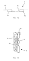
Le dispositif piézoélectrique 3 comporte dans ces exemples un élément piézoélectrique 70 réalisé en un matériau piézoélectrique et une membrane 71. Comme on peut le voir sur les
Dans l'exemple de la
Comme on peut le voir à la
En variante, comme représenté à la
L'invention n'est pas limitée à un élément piézoélectrique de forme annulaire. L'élément piézoélectrique peut comporter une sonotrode comme divulgué dans la demande internationale
La membrane perforée présente par exemple un diamètre supérieur ou égal à 6 mm, par exemple égal à 7 mm. La membrane comporte par exemple plus de 100 trous, par exemple 150 trous.The perforated membrane has for example a diameter greater than or equal to 6 mm, for example equal to 7 mm. The membrane comprises, for example, more than 100 holes, for example 150 holes.
Les trous ont par exemple un diamètre compris entre 20 µm et 40 µm, par exemple égal à 30 µm.The holes have for example a diameter of between 20 microns and 40 microns, for example equal to 30 microns.
Les trous sont par exemple situés dans la région centrale de la membrane.The holes are for example located in the central region of the membrane.
La membrane est par exemple collée sur une céramique d'épaisseur comprise entre 0,5 et 0,7 mm, par exemple égale à 0,6 mm, par exemple de diamètre extérieur égal à 20 mm, et de diamètre intérieur égal à 5 mm.The membrane is for example glued on a ceramic having a thickness of between 0.5 and 0.7 mm, for example equal to 0.6 mm, for example with an outer diameter of 20 mm, and an internal diameter equal to 5 mm. .
La céramique est par exemple excitée par une tension sinusoïdale à 100 kHz de 100 crête à crête.The ceramic is for example excited by a sinusoidal voltage 100 kHz 100 peak to peak.
Le circuit de contrôle 12 peut fournir le courant d'excitation de l'anneau en matériau piézoélectrique, lorsque l'élément piézoélectrique a la forme d'un anneau, et comporter les composants électroniques permettant éventuellement de maintenir la fréquence d'excitation à la valeur de résonnance.The
Le réservoir 20 peut être lié au boîtier 22 de manière détachable, le cas échéant, afin par exemple de permettre son remplacement tout en conservant le dispositif piézoélectrique 3.The
Le réservoir 20 peut éventuellement être réalisé de manière à permettre son rechargement en produit et peut comporter une ouverture à cet effet.The
Le boîtier 22 loge, dans l'exemple de la
La chambre 27 peut présenter un volume inférieur ou égal à 1 ml, par exemple un volume compris entre 0,25 et 0,75 ml.The
Le débit de produit vers la chambre 27 lors de la pulvérisation est compris par exemple entre 0,1 g/mn et 5 g/mn, allant par exemple de 0,7 à 0,9 g/mn.The flow rate of product to the
La pompe 26 comporte par exemple deux organes rotatifs 28 et 29 qui tournent au contact l'un de l'autre, ce qui permet d'obturer la communication entre la chambre 27 et le réservoir 20 lorsque la pompe est à l'arrêt.The
La pompe 26 peut être mise en rotation grâce à un premier organe d'accouplement 30 accessible sur une face du boîtier 22, agencé pour coopérer avec un deuxième organe d'accouplement 31 qui n'est représenté que schématiquement à la
Le système de pulvérisation peut comporter, le cas échéant, un réducteur entre le moteur 13 et le deuxième organe d'accouplement 31.The spraying system may comprise, where appropriate, a gearbox between the
Le boîtier 22 comporte également, dans l'exemple considéré, des conducteurs électriques 32 destinés à l'alimentation électrique du dispositif piézoélectrique 3, le boîtier 2 logeant des contacts électriques correspondants reliés au circuit de contrôle 12.The
Lors de la mise en place de la recharge 30 dans le boîtier 2, les premier et deuxième organes d'accouplement 30 et 31 coopèrent et les conducteurs 32 peuvent être alimentés par le circuit de contrôle 12.During the introduction of the
Le fonctionnement du système de pulvérisation 1 au cours du cycle de pulvérisation est par exemple le suivant, comme illustré à la
Tout d'abord, une pression sur le bouton-poussoir 15 est détectée par le circuit de contrôle 12, à l'étape 40.First, pressing the push-
Le circuit 12 peut commander alors le fonctionnement du dispositif piézoélectrique 3 à l'étape 41, puis celui du moteur 13 afin de provoquer à l'étape 42 la mise en circulation du produit vers la chambre 27.The
La pulvérisation peut avoir lieu, par exemple, tant que l'utilisateur maintient enfoncé le bouton-poussoir 15.The spraying can take place, for example, as long as the user holds down the
Lorsque le relâchement de celui-ci est détecté à l'étape 43, le fonctionnement du dispositif piézoélectrique 3 peut être maintenu tandis que le sens de rotation du moteur 13 est inversé, de manière à ce que la pompe 26 vide la chambre 27. Après une durée prédéfinie, le dispositif piézoélectrique 3 peut être arrêté, à l'étape 45.When the release thereof is detected in
Un produit même relativement visqueux peut être pulvérisé à plusieurs reprises par le dispositif de pulvérisation piézoélectrique, car le séchage et la formation d'un important dépôt solide de produit dans la chambre d'alimentation, entre deux utilisations espacées dans le temps, est évité.Even a relatively viscous product can be repeatedly sprayed by the piezoelectric spraying device, since drying and the formation of a large solid deposit of product in the feed chamber between two time-spaced uses is avoided.
La chambre 27 peut être alimentée par un canal 48 situé en partie inférieure de celle-ci. Ce canal 48 présente de préférence une faible section.The
Le circuit de contrôle 12 peut être agencé pour signaler à l'utilisateur grâce à l'inclinomètre 19, par exemple en émettant un signal lumineux et/ou sonore, que le système de pulvérisation 1 n'est pas dans l'orientation convenant le mieux au vidage complet de la chambre 27, en l'espèce tête en haut dans l'exemple de la
Le circuit de contrôle 12 peut encore, le cas échéant, comptabiliser le temps de fonctionnement du moteur 13 lorsque celui-ci entraine la pompe 26 de manière à fournir du produit à la chambre 27. Ce temps de fonctionnement ainsi comptabilisé peut être comparé à une valeur prédéfinie et le circuit de contrôle 12 peut être agencé pour avertir l'utilisateur du vidage imminent du réservoir 20 en émettant par exemple un signal sonore et/ou lumineux.The
L'avertisseur 17 est par exemple une LED qui change de couleur ou qui clignote lorsque le réservoir 20 est vide ou pratiquement vide. Cette LED peut également s'allumer pour signaler le bon fonctionnement du dispositif.The
Une fois vide, la recharge 10 peut être enlevée et remplacée par une nouvelle recharge, dont le réservoir 20 est plein.Once empty, the
L'invention n'est pas limitée à un moyen d'entraînement particulier pour faire circuler le produit vers la chambre 27 depuis le réservoir 20 ou inversement, et l'on peut utiliser divers types de pompes, par exemple utiliser une pompe péristaltique, à engrenages ou à vis.The invention is not limited to a particular drive means for circulating the product to the
Le réservoir 20 peut encore être délimité au moins partiellement par un piston 65, comme illustré à la
L'invention n'est pas limitée à la pulvérisation d'un produit unique et le boîtier 2 peut par exemple recevoir au moins deux recharges qui sont par exemple associées chacune à un dispositif de pulvérisation 3, le boîtier 2 pouvant comporter dans ce cas deux ouvertures 4a et 4b pour la pulvérisation respectivement de chacun des produits, comme illustré à la
Le système de pulvérisation 1 peut alors comporter un sélecteur 52 qui permet à l'utilisateur de choisir l'un ou l'autre des produits, voire de permettre la pulvérisation simultanée des deux produits avec un rapport déterminé par l'utilisateur, le circuit de contrôle pouvant par exemple dans ce cas commander les moteurs respectifs d'entraînement des pompes correspondantes avec des vitesses de rotation différentes en fonction de la proportion relative des produits à pulvériser.The
Les produits peuvent également être pulvérisés ensemble à travers une ouverture unique, comme illustré à la
Dans ce cas, le système de pulvérisation peut comporter deux réservoirs contenant respectivement les deux produits à pulvériser et des pompes correspondantes permettant d'alimenter une chambre unique associée au dispositif de pulvérisation.In this case, the spraying system may comprise two tanks respectively containing the two products to be sprayed and corresponding pumps for feeding a single chamber associated with the spraying device.
Le dispositif piézoélectrique peut être réalisé de diverses manières et comporter par exemple toute forme de membrane vibrante. L'invention n'est pas limitée non plus à une chambre d'alimentation du dispositif piézoélectrique de forme particulière. La forme de la chambre d'alimentation du dispositif piézoélectrique pourra notamment dépendre de la forme de la membrane vibrante.The piezoelectric device can be made in various ways and comprise for example any form of vibrating membrane. The invention is not limited either to a feed chamber of the piezoelectric device of particular shape. The shape of the feed chamber of the piezoelectric device may in particular depend on the shape of the vibrating membrane.
Le cas échéant, la recharge peut comporter des moyens pour renseigner le circuit de contrôle 12 sur la nature du produit contenu à l'intérieur, par exemple des reliefs coopérant avec des contacteurs du boîtier et dont l'état est analysé par le circuit de contrôle.If necessary, the recharging may comprise means for informing the
La recharge peut aussi comporter une mémoire électronique ou un code à barres contenant une information représentative du produit contenu à l'intérieur ainsi éventuellement que des caractéristiques additionnelles, telles que par exemple une information relative à des conditions de pulvérisation du produit, par exemple le débit d'alimentation du dispositif piézoélectrique.The refill can also comprise an electronic memory or a barcode containing information representative of the product contained inside, and possibly also additional characteristics, such as, for example, information relating to the spraying conditions of the product, for example the flow rate. supply of the piezoelectric device.
Tout type de dispositif piézoélectrique adapté à pulvériser le produit concerné est utilisable.Any type of piezoelectric device suitable for spraying the product concerned can be used.
Le dispositif piézoélectrique peut par exemple présenter une forme telle que divulguée dans la demande
L'expression « comportant un » doit être comprise comme étant synonyme de « comportant au moins un », sauf si le contraire est spécifié.The expression "having one" shall be understood as being synonymous with "having at least one", unless the opposite is specified.
Claims (26)
Applications Claiming Priority (1)
| Application Number | Priority Date | Filing Date | Title |
|---|---|---|---|
| FR0655746A FR2910254B1 (en) | 2006-12-20 | 2006-12-20 | PIEZOELECTRIC SPRAY SYSTEM AND CORRESPONDING REFILL |
Publications (2)
| Publication Number | Publication Date |
|---|---|
| EP1935505A1 true EP1935505A1 (en) | 2008-06-25 |
| EP1935505B1 EP1935505B1 (en) | 2013-04-24 |
Family
ID=38229526
Family Applications (1)
| Application Number | Title | Priority Date | Filing Date |
|---|---|---|---|
| EP07123600.4A Not-in-force EP1935505B1 (en) | 2006-12-20 | 2007-12-19 | Piezoelectric spraying system and corresponding refill |
Country Status (5)
| Country | Link |
|---|---|
| US (2) | US20080277495A1 (en) |
| EP (1) | EP1935505B1 (en) |
| JP (1) | JP2008155207A (en) |
| ES (1) | ES2421928T3 (en) |
| FR (1) | FR2910254B1 (en) |
Cited By (1)
| Publication number | Priority date | Publication date | Assignee | Title |
|---|---|---|---|---|
| FR2929862A1 (en) * | 2008-04-11 | 2009-10-16 | Oreal | Product or composition i.e. perfume, spraying assembly, has surface supported on apparatus when cartridge is placed in apparatus, for maintaining electrical contacts of cartridge in support against corresponding contacts of apparatus |
Families Citing this family (9)
| Publication number | Priority date | Publication date | Assignee | Title |
|---|---|---|---|---|
| FR2927238B1 (en) * | 2008-02-13 | 2012-08-31 | Oreal | SPRAY DEVICE COMPRISING A SOUNDRODE |
| FR2927240B1 (en) * | 2008-02-13 | 2011-11-11 | Oreal | SPRAY HEAD COMPRISING A SINGOTRODE, RUNWAYED BY A CANAL OF THE PRODUCT |
| FR2927237B1 (en) * | 2008-02-13 | 2011-12-23 | Oreal | DEVICE FOR SPRAYING A COSMETIC PRODUCT WITH HOT OR COLD AIR BLOWING |
| US20130079733A1 (en) * | 2009-11-18 | 2013-03-28 | Reckitt Benckiser Llc | Surface Treatment Device and Method |
| US20140056732A1 (en) * | 2012-08-22 | 2014-02-27 | Magna Powertrain | Hybrid variable external gear pump |
| US10112203B2 (en) | 2013-04-17 | 2018-10-30 | S.C. Johnson & Son, Inc. | Portable volatile material dispenser and method of simulating a flame in same |
| US11077221B2 (en) | 2016-01-25 | 2021-08-03 | S. C. Johnson & Son, Inc. | Volatile dispenser for use in volatile dispensing systems |
| US10994042B2 (en) | 2016-01-25 | 2021-05-04 | S. C. Johnson & Son, Inc. | Heated air freshener |
| US10940226B2 (en) | 2016-03-01 | 2021-03-09 | S. C. Johnson & Son, Inc. | Dispenser |
Citations (5)
| Publication number | Priority date | Publication date | Assignee | Title |
|---|---|---|---|---|
| US4702418A (en) * | 1985-09-09 | 1987-10-27 | Piezo Electric Products, Inc. | Aerosol dispenser |
| WO1991016997A1 (en) * | 1990-05-09 | 1991-11-14 | Siemens Aktiengesellschaft | Ultrasonic aerosol dispenser for hair lacquer |
| US5970974A (en) | 1995-03-14 | 1999-10-26 | Siemens Aktiengesellschaft | Dosating unit for an ultrasonic atomizer device |
| WO2005075095A1 (en) * | 2004-02-09 | 2005-08-18 | Matsushita Electric Works, Ltd. | Electrostatic spraying device |
| US20060062408A1 (en) * | 2004-09-20 | 2006-03-23 | Samsung Electronics Co., Ltd. | Mobile phone having perfume spraying apparatus |
Family Cites Families (22)
| Publication number | Priority date | Publication date | Assignee | Title |
|---|---|---|---|---|
| DE2445791C2 (en) * | 1974-09-25 | 1984-04-19 | Siemens AG, 1000 Berlin und 8000 München | Ultrasonic liquid atomizer |
| US4730751A (en) * | 1986-05-16 | 1988-03-15 | Leonard Mackles | Squeeze bottle powder dispenser |
| US4790454A (en) * | 1987-07-17 | 1988-12-13 | S. C. Johnson & Son, Inc. | Self-contained apparatus for admixing a plurality of liquids |
| US5171306A (en) * | 1991-03-13 | 1992-12-15 | Vo Van T | Eyedrop delivery system |
| ATE131421T1 (en) * | 1991-12-04 | 1995-12-15 | The Technology Partnership Plc | DEVICE AND METHOD FOR GENERATING LIQUID DROPS |
| GB9225098D0 (en) * | 1992-12-01 | 1993-01-20 | Coffee Ronald A | Charged droplet spray mixer |
| GB9306680D0 (en) * | 1993-03-31 | 1993-05-26 | The Technology Partnership Ltd | Fluid droplet apparatus |
| US5676129A (en) * | 1996-03-14 | 1997-10-14 | Oneida Research Services, Inc. | Dosage counter for metered dose inhaler (MDI) systems using a miniature pressure sensor |
| FR2750678B1 (en) * | 1996-07-05 | 1998-10-30 | Valois | DEVICE FOR BIPHASIC DELIVERY OF A SINGLE DOSE |
| US6296811B1 (en) * | 1998-12-10 | 2001-10-02 | Aurora Biosciences Corporation | Fluid dispenser and dispensing methods |
| JP3312216B2 (en) * | 1998-12-18 | 2002-08-05 | オムロン株式会社 | Spraying equipment |
| US6341732B1 (en) * | 2000-06-19 | 2002-01-29 | S. C. Johnson & Son, Inc. | Method and apparatus for maintaining control of liquid flow in a vibratory atomizing device |
| FR2817844B1 (en) * | 2000-12-08 | 2003-03-28 | Valois Sa | FLUID PRODUCT DISPENSER |
| DE20114352U1 (en) * | 2001-08-30 | 2003-01-16 | Klocke Verpackungs-Service GmbH, 76356 Weingarten | Air fresheners |
| US6913205B2 (en) * | 2001-10-30 | 2005-07-05 | Valois S.A.S. | Fluid product distributor |
| FR2832987B1 (en) * | 2001-12-04 | 2004-07-09 | Valois Sa | FLUID PRODUCT DISPENSER |
| US6651844B2 (en) * | 2002-02-22 | 2003-11-25 | Schering Corporation | Spray dispenser counter |
| US6969008B2 (en) * | 2003-01-29 | 2005-11-29 | S. C. Johnson & Son, Inc. | Point of purchase fragrance sampling |
| FR2861460B1 (en) * | 2003-10-28 | 2007-03-09 | Valois Sas | DEVICE FOR SPRAYING FLUID PRODUCT. |
| FR2879482B1 (en) * | 2004-12-20 | 2007-03-30 | Oreal | DEVICE FOR SPRAYING A PRODUCT, IN PARTICULAR A FRAGRANCE |
| US20070196402A1 (en) * | 2006-01-27 | 2007-08-23 | L'oreal | Method of preparing a cosmetic composition, and an assembly and a refill for implementing such a method |
| FR2912936B1 (en) * | 2007-02-23 | 2011-12-16 | Oreal | DEVICE FOR SPRAYING A BRILLIANCE COMPOSITION |
-
2006
- 2006-12-20 FR FR0655746A patent/FR2910254B1/en not_active Expired - Fee Related
-
2007
- 2007-12-19 ES ES07123600T patent/ES2421928T3/en active Active
- 2007-12-19 EP EP07123600.4A patent/EP1935505B1/en not_active Not-in-force
- 2007-12-20 JP JP2007328189A patent/JP2008155207A/en active Pending
- 2007-12-20 US US12/004,073 patent/US20080277495A1/en not_active Abandoned
-
2011
- 2011-01-21 US US13/010,965 patent/US20110114750A1/en not_active Abandoned
Patent Citations (5)
| Publication number | Priority date | Publication date | Assignee | Title |
|---|---|---|---|---|
| US4702418A (en) * | 1985-09-09 | 1987-10-27 | Piezo Electric Products, Inc. | Aerosol dispenser |
| WO1991016997A1 (en) * | 1990-05-09 | 1991-11-14 | Siemens Aktiengesellschaft | Ultrasonic aerosol dispenser for hair lacquer |
| US5970974A (en) | 1995-03-14 | 1999-10-26 | Siemens Aktiengesellschaft | Dosating unit for an ultrasonic atomizer device |
| WO2005075095A1 (en) * | 2004-02-09 | 2005-08-18 | Matsushita Electric Works, Ltd. | Electrostatic spraying device |
| US20060062408A1 (en) * | 2004-09-20 | 2006-03-23 | Samsung Electronics Co., Ltd. | Mobile phone having perfume spraying apparatus |
Cited By (1)
| Publication number | Priority date | Publication date | Assignee | Title |
|---|---|---|---|---|
| FR2929862A1 (en) * | 2008-04-11 | 2009-10-16 | Oreal | Product or composition i.e. perfume, spraying assembly, has surface supported on apparatus when cartridge is placed in apparatus, for maintaining electrical contacts of cartridge in support against corresponding contacts of apparatus |
Also Published As
| Publication number | Publication date |
|---|---|
| FR2910254B1 (en) | 2009-04-17 |
| JP2008155207A (en) | 2008-07-10 |
| ES2421928T3 (en) | 2013-09-06 |
| FR2910254A1 (en) | 2008-06-27 |
| EP1935505B1 (en) | 2013-04-24 |
| US20080277495A1 (en) | 2008-11-13 |
| US20110114750A1 (en) | 2011-05-19 |
Similar Documents
| Publication | Publication Date | Title |
|---|---|---|
| EP1935505B1 (en) | Piezoelectric spraying system and corresponding refill | |
| EP0401060B1 (en) | Method and electrical, electronic and mechanical device for dispensing, metering or diffusing liquid or gaseous aromas, medicines and other liquid or viscous product | |
| EP0546898B1 (en) | Rechargeable device for spraying a fluid | |
| EP0555447B1 (en) | Combination of an aerosol can with a can pressurizing device | |
| EP2090370B1 (en) | Method of spraying a cosmetic product with blowing of hot or cold air | |
| EP2707305B1 (en) | Fluid product dispenser | |
| FR2943324A1 (en) | DEVICE FOR DISPENSING A PASSIVE LIQUID PRODUCT WITH A LOW VOLUME DOSING PUMP | |
| WO1995024935A1 (en) | Dynamic dispenser for a substance such as a perfume | |
| FR2879482A1 (en) | DEVICE FOR SPRAYING A PRODUCT, IN PARTICULAR A FRAGRANCE | |
| EP1935280B1 (en) | Method for dispensing a product sprayed by a piezoelectric spraying system and spraying system for implementing such a method | |
| FR2903586A1 (en) | APPLICATOR DISTRIBUTOR OF COSMETIC MATERIAL WITH PUSHER | |
| FR3023269A1 (en) | FLUID PRODUCT DISPENSER. | |
| EP2475465A1 (en) | Packaging and dispensing device including a miniature electric pump | |
| FR2892276A1 (en) | Cosmetic or dermatological product e.g. perfume, applicator-dispenser for user`s e.g. face, has switch controlling electric circuit so that application unit produces massaging effect on support, during application of product on support | |
| EP4291281B1 (en) | Microneedle applicator | |
| EP1497201A2 (en) | Fluid product dispenser | |
| EP1596991A2 (en) | Fluid product distributor | |
| FR2918855A1 (en) | Product's e.g. make-up product, raisin or stick e.g. lipstick, conditioning and applying device, has vibration generator connected to support cupule in manner to transmit vibrations emitted by generator to support cupule | |
| FR2752310A1 (en) | Regulating pressure in fluid circuit | |
| FR3044558A1 (en) | DEVICE, CONNECTED SYSTEM, AND AROMATIC LIQUID DIFFUSION CAPSULE | |
| EP1230031B1 (en) | Fast rate pump | |
| EP0557194A1 (en) | Dispenser with electric motor | |
| EP1596994B1 (en) | Fluid product distributor | |
| WO2023208890A1 (en) | Device for dispensing a fluid product | |
| FR2689036A1 (en) | Electrically operated pump dispenser for small measured quantities |
Legal Events
| Date | Code | Title | Description |
|---|---|---|---|
| PUAI | Public reference made under article 153(3) epc to a published international application that has entered the european phase |
Free format text: ORIGINAL CODE: 0009012 |
|
| 17P | Request for examination filed |
Effective date: 20071219 |
|
| AK | Designated contracting states |
Kind code of ref document: A1 Designated state(s): AT BE BG CH CY CZ DE DK EE ES FI FR GB GR HU IE IS IT LI LT LU LV MC MT NL PL PT RO SE SI SK TR |
|
| AX | Request for extension of the european patent |
Extension state: AL BA HR MK RS |
|
| 17Q | First examination report despatched |
Effective date: 20080819 |
|
| AKX | Designation fees paid |
Designated state(s): AT BE BG CH CY CZ DE DK EE ES FI FR GB GR HU IE IS IT LI LT LU LV MC MT NL PL PT RO SE SI SK TR |
|
| GRAP | Despatch of communication of intention to grant a patent |
Free format text: ORIGINAL CODE: EPIDOSNIGR1 |
|
| GRAS | Grant fee paid |
Free format text: ORIGINAL CODE: EPIDOSNIGR3 |
|
| GRAA | (expected) grant |
Free format text: ORIGINAL CODE: 0009210 |
|
| AK | Designated contracting states |
Kind code of ref document: B1 Designated state(s): AT BE BG CH CY CZ DE DK EE ES FI FR GB GR HU IE IS IT LI LT LU LV MC MT NL PL PT RO SE SI SK TR |
|
| REG | Reference to a national code |
Ref country code: GB Ref legal event code: FG4D Free format text: NOT ENGLISH |
|
| REG | Reference to a national code |
Ref country code: CH Ref legal event code: EP |
|
| REG | Reference to a national code |
Ref country code: AT Ref legal event code: REF Ref document number: 608273 Country of ref document: AT Kind code of ref document: T Effective date: 20130515 |
|
| REG | Reference to a national code |
Ref country code: IE Ref legal event code: FG4D Free format text: LANGUAGE OF EP DOCUMENT: FRENCH |
|
| REG | Reference to a national code |
Ref country code: DE Ref legal event code: R096 Ref document number: 602007029961 Country of ref document: DE Effective date: 20130620 |
|
| REG | Reference to a national code |
Ref country code: AT Ref legal event code: MK05 Ref document number: 608273 Country of ref document: AT Kind code of ref document: T Effective date: 20130424 |
|
| REG | Reference to a national code |
Ref country code: LT Ref legal event code: MG4D |
|
| REG | Reference to a national code |
Ref country code: NL Ref legal event code: VDEP Effective date: 20130424 |
|
| PG25 | Lapsed in a contracting state [announced via postgrant information from national office to epo] |
Ref country code: IS Free format text: LAPSE BECAUSE OF FAILURE TO SUBMIT A TRANSLATION OF THE DESCRIPTION OR TO PAY THE FEE WITHIN THE PRESCRIBED TIME-LIMIT Effective date: 20130824 Ref country code: FI Free format text: LAPSE BECAUSE OF FAILURE TO SUBMIT A TRANSLATION OF THE DESCRIPTION OR TO PAY THE FEE WITHIN THE PRESCRIBED TIME-LIMIT Effective date: 20130424 Ref country code: GR Free format text: LAPSE BECAUSE OF FAILURE TO SUBMIT A TRANSLATION OF THE DESCRIPTION OR TO PAY THE FEE WITHIN THE PRESCRIBED TIME-LIMIT Effective date: 20130725 Ref country code: SE Free format text: LAPSE BECAUSE OF FAILURE TO SUBMIT A TRANSLATION OF THE DESCRIPTION OR TO PAY THE FEE WITHIN THE PRESCRIBED TIME-LIMIT Effective date: 20130424 Ref country code: SI Free format text: LAPSE BECAUSE OF FAILURE TO SUBMIT A TRANSLATION OF THE DESCRIPTION OR TO PAY THE FEE WITHIN THE PRESCRIBED TIME-LIMIT Effective date: 20130424 Ref country code: AT Free format text: LAPSE BECAUSE OF FAILURE TO SUBMIT A TRANSLATION OF THE DESCRIPTION OR TO PAY THE FEE WITHIN THE PRESCRIBED TIME-LIMIT Effective date: 20130424 Ref country code: LT Free format text: LAPSE BECAUSE OF FAILURE TO SUBMIT A TRANSLATION OF THE DESCRIPTION OR TO PAY THE FEE WITHIN THE PRESCRIBED TIME-LIMIT Effective date: 20130424 Ref country code: PT Free format text: LAPSE BECAUSE OF FAILURE TO SUBMIT A TRANSLATION OF THE DESCRIPTION OR TO PAY THE FEE WITHIN THE PRESCRIBED TIME-LIMIT Effective date: 20130826 |
|
| PG25 | Lapsed in a contracting state [announced via postgrant information from national office to epo] |
Ref country code: LV Free format text: LAPSE BECAUSE OF FAILURE TO SUBMIT A TRANSLATION OF THE DESCRIPTION OR TO PAY THE FEE WITHIN THE PRESCRIBED TIME-LIMIT Effective date: 20130424 Ref country code: CY Free format text: LAPSE BECAUSE OF FAILURE TO SUBMIT A TRANSLATION OF THE DESCRIPTION OR TO PAY THE FEE WITHIN THE PRESCRIBED TIME-LIMIT Effective date: 20130424 Ref country code: BG Free format text: LAPSE BECAUSE OF FAILURE TO SUBMIT A TRANSLATION OF THE DESCRIPTION OR TO PAY THE FEE WITHIN THE PRESCRIBED TIME-LIMIT Effective date: 20130724 Ref country code: PL Free format text: LAPSE BECAUSE OF FAILURE TO SUBMIT A TRANSLATION OF THE DESCRIPTION OR TO PAY THE FEE WITHIN THE PRESCRIBED TIME-LIMIT Effective date: 20130424 |
|
| PG25 | Lapsed in a contracting state [announced via postgrant information from national office to epo] |
Ref country code: CZ Free format text: LAPSE BECAUSE OF FAILURE TO SUBMIT A TRANSLATION OF THE DESCRIPTION OR TO PAY THE FEE WITHIN THE PRESCRIBED TIME-LIMIT Effective date: 20130424 Ref country code: SK Free format text: LAPSE BECAUSE OF FAILURE TO SUBMIT A TRANSLATION OF THE DESCRIPTION OR TO PAY THE FEE WITHIN THE PRESCRIBED TIME-LIMIT Effective date: 20130424 Ref country code: DK Free format text: LAPSE BECAUSE OF FAILURE TO SUBMIT A TRANSLATION OF THE DESCRIPTION OR TO PAY THE FEE WITHIN THE PRESCRIBED TIME-LIMIT Effective date: 20130424 Ref country code: EE Free format text: LAPSE BECAUSE OF FAILURE TO SUBMIT A TRANSLATION OF THE DESCRIPTION OR TO PAY THE FEE WITHIN THE PRESCRIBED TIME-LIMIT Effective date: 20130424 |
|
| PG25 | Lapsed in a contracting state [announced via postgrant information from national office to epo] |
Ref country code: NL Free format text: LAPSE BECAUSE OF FAILURE TO SUBMIT A TRANSLATION OF THE DESCRIPTION OR TO PAY THE FEE WITHIN THE PRESCRIBED TIME-LIMIT Effective date: 20130424 Ref country code: RO Free format text: LAPSE BECAUSE OF FAILURE TO SUBMIT A TRANSLATION OF THE DESCRIPTION OR TO PAY THE FEE WITHIN THE PRESCRIBED TIME-LIMIT Effective date: 20130424 |
|
| PLBE | No opposition filed within time limit |
Free format text: ORIGINAL CODE: 0009261 |
|
| STAA | Information on the status of an ep patent application or granted ep patent |
Free format text: STATUS: NO OPPOSITION FILED WITHIN TIME LIMIT |
|
| 26N | No opposition filed |
Effective date: 20140127 |
|
| REG | Reference to a national code |
Ref country code: DE Ref legal event code: R097 Ref document number: 602007029961 Country of ref document: DE Effective date: 20140127 |
|
| BERE | Be: lapsed |
Owner name: L'OREAL Effective date: 20131231 |
|
| REG | Reference to a national code |
Ref country code: DE Ref legal event code: R119 Ref document number: 602007029961 Country of ref document: DE |
|
| REG | Reference to a national code |
Ref country code: CH Ref legal event code: PL |
|
| GBPC | Gb: european patent ceased through non-payment of renewal fee |
Effective date: 20131219 |
|
| PG25 | Lapsed in a contracting state [announced via postgrant information from national office to epo] |
Ref country code: MC Free format text: LAPSE BECAUSE OF FAILURE TO SUBMIT A TRANSLATION OF THE DESCRIPTION OR TO PAY THE FEE WITHIN THE PRESCRIBED TIME-LIMIT Effective date: 20130424 Ref country code: LU Free format text: LAPSE BECAUSE OF FAILURE TO SUBMIT A TRANSLATION OF THE DESCRIPTION OR TO PAY THE FEE WITHIN THE PRESCRIBED TIME-LIMIT Effective date: 20131219 |
|
| REG | Reference to a national code |
Ref country code: IE Ref legal event code: MM4A |
|
| REG | Reference to a national code |
Ref country code: DE Ref legal event code: R119 Ref document number: 602007029961 Country of ref document: DE Effective date: 20140701 |
|
| REG | Reference to a national code |
Ref country code: FR Ref legal event code: ST Effective date: 20140829 |
|
| PG25 | Lapsed in a contracting state [announced via postgrant information from national office to epo] |
Ref country code: BE Free format text: LAPSE BECAUSE OF NON-PAYMENT OF DUE FEES Effective date: 20131231 Ref country code: LI Free format text: LAPSE BECAUSE OF NON-PAYMENT OF DUE FEES Effective date: 20131231 Ref country code: IE Free format text: LAPSE BECAUSE OF NON-PAYMENT OF DUE FEES Effective date: 20131219 Ref country code: DE Free format text: LAPSE BECAUSE OF NON-PAYMENT OF DUE FEES Effective date: 20140701 Ref country code: CH Free format text: LAPSE BECAUSE OF NON-PAYMENT OF DUE FEES Effective date: 20131231 |
|
| PG25 | Lapsed in a contracting state [announced via postgrant information from national office to epo] |
Ref country code: FR Free format text: LAPSE BECAUSE OF NON-PAYMENT OF DUE FEES Effective date: 20131231 Ref country code: GB Free format text: LAPSE BECAUSE OF NON-PAYMENT OF DUE FEES Effective date: 20131219 |
|
| PG25 | Lapsed in a contracting state [announced via postgrant information from national office to epo] |
Ref country code: TR Free format text: LAPSE BECAUSE OF FAILURE TO SUBMIT A TRANSLATION OF THE DESCRIPTION OR TO PAY THE FEE WITHIN THE PRESCRIBED TIME-LIMIT Effective date: 20130424 |
|
| REG | Reference to a national code |
Ref country code: ES Ref legal event code: FD2A Effective date: 20150715 |
|
| PG25 | Lapsed in a contracting state [announced via postgrant information from national office to epo] |
Ref country code: ES Free format text: LAPSE BECAUSE OF NON-PAYMENT OF DUE FEES Effective date: 20131220 Ref country code: HU Free format text: LAPSE BECAUSE OF FAILURE TO SUBMIT A TRANSLATION OF THE DESCRIPTION OR TO PAY THE FEE WITHIN THE PRESCRIBED TIME-LIMIT; INVALID AB INITIO Effective date: 20071219 |
|
| PG25 | Lapsed in a contracting state [announced via postgrant information from national office to epo] |
Ref country code: IT Free format text: LAPSE BECAUSE OF NON-PAYMENT OF DUE FEES Effective date: 20130424 Ref country code: MT Free format text: LAPSE BECAUSE OF FAILURE TO SUBMIT A TRANSLATION OF THE DESCRIPTION OR TO PAY THE FEE WITHIN THE PRESCRIBED TIME-LIMIT Effective date: 20130424 |
|
| PG25 | Lapsed in a contracting state [announced via postgrant information from national office to epo] |
Ref country code: IT Free format text: LAPSE BECAUSE OF NON-PAYMENT OF DUE FEES Effective date: 20131219 |