EP1925533A1 - Combined lock angle and torque sensor - Google Patents
Combined lock angle and torque sensor Download PDFInfo
- Publication number
- EP1925533A1 EP1925533A1 EP07010069A EP07010069A EP1925533A1 EP 1925533 A1 EP1925533 A1 EP 1925533A1 EP 07010069 A EP07010069 A EP 07010069A EP 07010069 A EP07010069 A EP 07010069A EP 1925533 A1 EP1925533 A1 EP 1925533A1
- Authority
- EP
- European Patent Office
- Prior art keywords
- steering angle
- damping
- steering column
- torque sensor
- output shaft
- Prior art date
- Legal status (The legal status is an assumption and is not a legal conclusion. Google has not performed a legal analysis and makes no representation as to the accuracy of the status listed.)
- Granted
Links
Images
Classifications
-
- B—PERFORMING OPERATIONS; TRANSPORTING
- B62—LAND VEHICLES FOR TRAVELLING OTHERWISE THAN ON RAILS
- B62D—MOTOR VEHICLES; TRAILERS
- B62D6/00—Arrangements for automatically controlling steering depending on driving conditions sensed and responded to, e.g. control circuits
- B62D6/08—Arrangements for automatically controlling steering depending on driving conditions sensed and responded to, e.g. control circuits responsive only to driver input torque
- B62D6/10—Arrangements for automatically controlling steering depending on driving conditions sensed and responded to, e.g. control circuits responsive only to driver input torque characterised by means for sensing or determining torque
-
- B—PERFORMING OPERATIONS; TRANSPORTING
- B62—LAND VEHICLES FOR TRAVELLING OTHERWISE THAN ON RAILS
- B62D—MOTOR VEHICLES; TRAILERS
- B62D15/00—Steering not otherwise provided for
- B62D15/02—Steering position indicators ; Steering position determination; Steering aids
- B62D15/021—Determination of steering angle
- B62D15/0215—Determination of steering angle by measuring on the steering column
-
- G—PHYSICS
- G01—MEASURING; TESTING
- G01B—MEASURING LENGTH, THICKNESS OR SIMILAR LINEAR DIMENSIONS; MEASURING ANGLES; MEASURING AREAS; MEASURING IRREGULARITIES OF SURFACES OR CONTOURS
- G01B7/00—Measuring arrangements characterised by the use of electric or magnetic techniques
- G01B7/30—Measuring arrangements characterised by the use of electric or magnetic techniques for measuring angles or tapers; for testing the alignment of axes
-
- G—PHYSICS
- G01—MEASURING; TESTING
- G01D—MEASURING NOT SPECIALLY ADAPTED FOR A SPECIFIC VARIABLE; ARRANGEMENTS FOR MEASURING TWO OR MORE VARIABLES NOT COVERED IN A SINGLE OTHER SUBCLASS; TARIFF METERING APPARATUS; MEASURING OR TESTING NOT OTHERWISE PROVIDED FOR
- G01D5/00—Mechanical means for transferring the output of a sensing member; Means for converting the output of a sensing member to another variable where the form or nature of the sensing member does not constrain the means for converting; Transducers not specially adapted for a specific variable
- G01D5/12—Mechanical means for transferring the output of a sensing member; Means for converting the output of a sensing member to another variable where the form or nature of the sensing member does not constrain the means for converting; Transducers not specially adapted for a specific variable using electric or magnetic means
- G01D5/14—Mechanical means for transferring the output of a sensing member; Means for converting the output of a sensing member to another variable where the form or nature of the sensing member does not constrain the means for converting; Transducers not specially adapted for a specific variable using electric or magnetic means influencing the magnitude of a current or voltage
- G01D5/20—Mechanical means for transferring the output of a sensing member; Means for converting the output of a sensing member to another variable where the form or nature of the sensing member does not constrain the means for converting; Transducers not specially adapted for a specific variable using electric or magnetic means influencing the magnitude of a current or voltage by varying inductance, e.g. by a movable armature
- G01D5/2006—Mechanical means for transferring the output of a sensing member; Means for converting the output of a sensing member to another variable where the form or nature of the sensing member does not constrain the means for converting; Transducers not specially adapted for a specific variable using electric or magnetic means influencing the magnitude of a current or voltage by varying inductance, e.g. by a movable armature by influencing the self-induction of one or more coils
- G01D5/202—Mechanical means for transferring the output of a sensing member; Means for converting the output of a sensing member to another variable where the form or nature of the sensing member does not constrain the means for converting; Transducers not specially adapted for a specific variable using electric or magnetic means influencing the magnitude of a current or voltage by varying inductance, e.g. by a movable armature by influencing the self-induction of one or more coils by movable a non-ferromagnetic conductive element
Definitions
- the invention relates to a combined steering angle and torque sensor which generates two absolute angle measurement signals over an angular range of 360 degrees on an inductive basis with eddy current damping.
- the steering column is usually divided by a torsion element at a joint.
- the input shaft faces the steering wheel and carries in the vicinity of the twisted joint a first actuator.
- the output shaft of the steering column is associated with the steering gear and carries in the vicinity of the twisted joint a second actuator.
- the steering angle and the torque have so far been detected by two separate sensors with different operating principles (inductive, optical, capacitive, magnetic, etc.).
- Many current torque sensors due to the high resolution required, allow only a small torque range, expressed as an angle of the order of +/- 10 degrees.
- the steering angle range also depends on many multi-turn sensors the required accuracy and is often limited. Since these sensors are used in safety-relevant applications, redundancy is increasingly required. Overall, a large space is often needed.
- the object of the invention is to provide a combined sensor in a small space despite redundancy and dual function steering angle / torque.
- the solution succeeds with a device according to claim 1.
- the invention is particularly troublesome with code discs and similar actuators whose structures repeat periodically on the circumference and which allow only incremental measurements.
- the invention generates according to claim 1 on a given circumference two absolute angle measurement signals.
- the invention interferes with complex multiturn sensors.
- an inductive steering angle and torque sensor has been found on the basis of eddy current damping.
- a first damper rotor is connected to the input shaft of the steering column (divided by a torsion element), a second damper rotor is located at the opposite end of the output shaft.
- Both damper rotors carry a passive actuator for the eddy current damping, in such a way that they act angularly offset from each other in the same measurement plane.
- a sensor carrier which is penetrated by the split steering column at right angles and equipped with several flat coils in the full angular range of 360 degrees.
- the two location-selective actuation elements act at two different locations, which can conveniently be offset by about 180 degrees.
- the signals of all, preferably four, flat coils are always measured.
- the resulting from the output shaft absolute angle measurement signal (or a sum signal from the two measurements) then represents the steering angle, while the torque can be derived from the difference between the two angle measurement signals and the elasticity of the torsion.
- a second housing-fixed sensor carrier is provided in the vicinity of the joint of the split steering column, which is also traversed at right angles by the steering column. He is the same as the first Carrier in full angular range of 360 degrees with other flat coils, but equipped in a second measurement level.
- the damping rotors each carry a second actuating element on the rear side, again without periodically repeated structures, for the second measuring plane.
- a multi-turn counter is still needed.
- the magnetic tablet multiturn counter is incrementally driven by a follower attached to the damper rotor of the output shaft every full revolution of the steering column.
- the step is one-seventh of a full revolution.
- the magnetic tablet generates incremental counting signals in Hall sensors, which are additionally arranged on the sensor carrier. Each step signal represents one complete revolution of the output shaft of the steering column.
- any other non-contact transmission principle for the multi-turn sensor can be applied.
- the evaluation of the measuring signals is digital.
- the sensor coils are, for example, each part of a Colpitts oscillator whose digital output signal can be evaluated directly.
- the oscillator frequency represents a largely linear measure of the measuring angle in the measuring range.
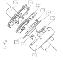
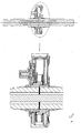
- FIG. 1a a housing 9 together with the bottom and a housing cover 1 in the axial direction of the steering column 2a, 6a pulled apart, so that an embodiment of the combination sensor according to the invention is visible.
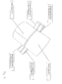
- FIG. 8 the installation of this housing 1, 9 is shown in more detail on the steering column 2a, 6a.
- the steering column is divided by an input shaft 2a and an output shaft 6a.
- On the output shaft 6a sits a worm wheel, which belongs to the transmission housing.
- the multi-turn sensor 7 can also be arranged on the input shaft 2a for reasons of saving space.
- the axial section shows the input shaft 2 a, the output shaft 6 a and an inner torsion bar 11.
- the elastic rotation of the torsion bar 11 determines the relative angular difference of the shaft ends at the joint 12 as a function of the attacking, transmitted from the steering wheel forth torque.
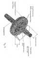
- Figure 6 is still an enlarged section of the sensor shown in section.
- a damping rotor 2 is connected to the end of the input shaft 2 a.
- damping is meant from now on the electrical eddy current damping, which occurs as inductance change of measuring coils.
- a corresponding damping rotor 6 is connected to the end of the output shaft 6a.
- FIG. 5 with a sensor board or a sensor carrier is called, which carries a plurality of flat coils 13 in an annular arrangement.
- the sensor carrier 5 is fixed to the housing (1, 9) mounted and is penetrated by the split steering column 2a, 6a at right angles.
- the arrangement of four flat coils 13 is shown in detail in the plan. It has proved to be expedient not to extend the dividing line between two flat coils 13 exactly in the radial direction. Depending on the accuracy requirements, the number and shape of the flat coils is defined.
- each of the damping rotors 2 and 6 carries an actuating element 14 in that measuring plane which faces the flat coils 12.
- the actuators 14 are, for example, thin aluminum plates on the end faces of the damping rotors 2 and 6 are applied. They act as an eddy current brake in a location-selective manner on the flat coils 13 according to FIG.
- the length of the actuating element 14 is less than 1 ⁇ 4 of the circumference, so that the eddy current damping in a location-selective manner acts on two of the four flat coils 13 according to FIG. Important for the location-selective operation is that the actuating element 14 does not extend over the entire circumference and has no periodically repeating structures.
- the actuating elements 2b and 6b act on the circular arc coil arrangement 13 at two different locations. In particular, they are offset by about 180 degrees in the same measurement plane. Since the signals generated by the flat coils 13 are constantly measured, there are always at least two absolute angle measurement signals available over the entire circumference of 360 degrees. From these signals, both the steering angle and the torque can be determined by a digital evaluation circuit.
- a redundancy is often required, which easily copes with the failure of individual components.
- this redundancy is very easy to achieve.
- a further sensor carrier 3 is provided on the other side of the joint 12, which forms a further measuring plane with its flat coils 13b.
- the same damping rotors 2 and 6 carry for this purpose on the back of the first actuators 2b and 6b further actuators 2c and 6c, which are effective at a small distance from the other flat coils 13b in the second measurement plane. Structure and function of the other carrier board 3 are completely analog.
- the sensor structure according to FIG. 1 takes account of the fact that, in particular in the case of trucks, the steering angle can exceed the range of a full circumference of -180 degrees to +180 degrees.
- a multi-turn counter 7 is additionally arranged in the housing 1, 9.
- the multi-turn counter 7 is pulled out axially together with the housing bottom 9; in the installed state, it lies in a plane with the damping rotor of the output shaft 6a or the input shaft 2a. Then, the damping rotor 6 and the multi-turn counter 7 interlock, as the side view of Figure 5 reveals.
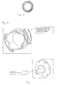
- FIG 3 carries the damping rotor 6 for this purpose at an outer location of the circumference of a driver 15 which causes a step-by-step entrainment of the Geneva wheel 7.
- the Geneva wheel 7 on the circumference seven driving elements 16 has been distributed.
- the multiturn counter 7 thus gives an indication of in which of seven revolution periods the steering column is located.
- the multi-turn counter 7 which consists of the special, matched to the driver of the damping rotor drive wheel, e.g. a magnetic tablet. With the aid of the magnetic tablet, the revolutions of the steering column are detected by the fact that on the sensor board 5, for example. two additional Hall sensors are arranged. The mechanics of the entrained Maltese wheel prevent rapid wear and noise emission compared to today's conventional gears. As a rule, the multi-turn-Geneva wheel 7 will only move from a steering angle of about +/- 170 ° and more.
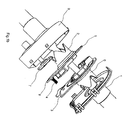
- FIG. 7 shows, as an alternative to FIG. 3 in conjunction with FIG. 1, a further exemplary embodiment for opposed damping rotors.
- the back of the nose which extends into the second measurement plane, but it is provided a second, separate nose for the other damping element.
- the angle data can be transmitted reliably, with high spatial resolution and in a timely manner to a central regulating and control device of the car, truck or commercial vehicle.
Landscapes
- Engineering & Computer Science (AREA)
- Chemical & Material Sciences (AREA)
- Combustion & Propulsion (AREA)
- Transportation (AREA)
- Mechanical Engineering (AREA)
- Physics & Mathematics (AREA)
- General Physics & Mathematics (AREA)
- Power Steering Mechanism (AREA)
- Measurement Of Length, Angles, Or The Like Using Electric Or Magnetic Means (AREA)
- Steering Control In Accordance With Driving Conditions (AREA)
- Steering Controls (AREA)
Abstract
Vorgestellt wird ein kombinierter Lenkwinkel- und Drehmomentsensor, der auf induktiver Basis mit Wirbelstromdämpfung zwei absolute Winkelmesssignale über einen Winkelbereich von 360 Grad erzeugt. Hierzu ist eine Lenksäule in üblicher Weise durch ein Torsionselement in eine Eingangswelle und eine relativ dazu tordierbare Ausgangswelle geteilt. Am Ende der Eingangswelle in der Nähe der Stoßstelle ist ein erster Dämpfungsrotor, am Ende der Ausgangswelle ein zweiter Dämpfungsrotor angeordnet. Von der geteilten Lenksäule wird ein Träger rechtwinklig durchsetzt, der im gesamten Winkelbereich von 360 Grad mit mehreren Flachspulen bestückt und gehäusefest angeordnet ist. Die zwei Dämpfungsrotoren tragen jeweils ein passives Betätigungselement für die Wirbelstromdämpfung, die jeweils ortsselektiv (ohne periodisch wiederholte Strukturen oder Kodespuren) auf die Flachspulen des Trägers einwirken. Aus den Signalen der Flachspulen lassen sich die zwei absoluten Winkelmesssignale (und daraus durch Summen- und Differenzbildung Lenkwinkel und Drehmoment) ermitteln. Die häufig geforderte Redundanz wird bei dieser Technologie sehr einfach durch einen weiteren Sensorträger (mit Flachspulen in einer weiteren Messebene) und durch die gleichen Dämpfungsrotoren (mit weiteren ortsselektiven Betätigungselementen in dieser weiteren Messebene) erzielt.Presented is a combined steering angle and torque sensor that generates two absolute angle measuring signals over an angular range of 360 degrees on an inductive basis with eddy current damping. For this purpose, a steering column is divided in the usual way by a torsion element in an input shaft and a relative to this twistable output shaft. At the end of the input shaft in the vicinity of the joint, a first damping rotor, at the end of the output shaft, a second damping rotor is arranged. From the split steering column, a carrier is traversed at right angles, which is equipped in the entire angular range of 360 degrees with multiple flat coils and fixed to the housing. The two damping rotors each carry a passive actuator for the eddy current damping, which act in each case location-selective (without periodically repeated structures or code traces) on the flat coils of the carrier. The signals of the flat coils can be used to determine the two absolute angle measurement signals (and from this sum and difference in the steering angle and torque). The frequently required redundancy in this technology is achieved very simply by a further sensor carrier (with flat coils in another measuring plane) and by the same damping rotors (with further location-selective actuating elements in this further measuring plane).
Description
Die Erfindung betrifft einen kombinierten Lenkwinkel-' und Drehmomentsensor, der auf induktiver Basis mit Wirbelstromdämpfung zwei absolute Winkelmesssignale über einen Winkelbereich von 360 Grad erzeugt.The invention relates to a combined steering angle and torque sensor which generates two absolute angle measurement signals over an angular range of 360 degrees on an inductive basis with eddy current damping.
Für solche Messungen ist die Lenksäule üblicherweise durch ein Torsionselement an einer Stoßstelle geteilt. Die Eingangswelle ist dem Lenkrad zugewandt und trägt in der Nähe der tordierten Stoßstelle ein erstes Betätigungselement. Die Ausgangswelle der Lenksäule ist dem Lenkgetriebe zugeordnet und trägt in der Nähe der tordierten Stoßstelle ein zweites Betätigungselement.For such measurements, the steering column is usually divided by a torsion element at a joint. The input shaft faces the steering wheel and carries in the vicinity of the twisted joint a first actuator. The output shaft of the steering column is associated with the steering gear and carries in the vicinity of the twisted joint a second actuator.
In diesem technischen Zusammenhang sind im Stand der Technik bekannt (i) eine induktive Messtechnik mittels Wirbelstromdämpfung, (ii) Messebenen senkrecht zur Drehachse sowie (iii) zwei ringscheibenförmige elektrische Dämpfungsglieder, die beidseitig des Torsionselementes an der Lenksäule angebracht sind, vgl. den Stand der Technik gemäß
Im PKW- und LKW- und NKW-Bereich werden der Lenkwinkel und das Drehmoment bisher durch zwei separate Sensoren mit verschiedenen Funktionsprinzipien (induktiv, optisch, kapazitiv, magnetisch usw.) erfasst. Viele derzeitige Drehmomentsensoren erlauben aufgrund der hohen Auflösung, die erforderlich ist, nur einen kleinen Drehmomentbereich, der als Winkel ausgedrückt in der Größenordnung von +/- 10 Grad liegt. Auch der Lenkwinkelbereich richtet sich bei vielen Multiturnsensoren nach der erforderlichen Genauigkeit und ist oft eingeschränkt. Da diese Sensoren in sicherheitsrelevanten Applikationen verwendet werden, wird zunehmend Redundanz verlangt. Insgesamt wird häufig ein großer Bauraum benötigt.In the car and truck and commercial vehicle sector, the steering angle and the torque have so far been detected by two separate sensors with different operating principles (inductive, optical, capacitive, magnetic, etc.). Many current torque sensors, due to the high resolution required, allow only a small torque range, expressed as an angle of the order of +/- 10 degrees. The steering angle range also depends on many multi-turn sensors the required accuracy and is often limited. Since these sensors are used in safety-relevant applications, redundancy is increasingly required. Overall, a large space is often needed.
Die Aufgabe der Erfindung besteht darin, trotz Redundanz und Doppelfunktion Lenkwinkel/Drehmoment einen kombinierten Sensor auf geringem Bauraum anzugeben. Die Lösung gelingt mit einer Vorrichtung nach dem Anspruch 1.The object of the invention is to provide a combined sensor in a small space despite redundancy and dual function steering angle / torque. The solution succeeds with a device according to
Die Erfindung stört sich insbesondere an Kodierscheiben und ähnlichen Betätigungselementen, deren Strukturen sich auf dem Kreisumfang periodisch wiederholen und die nur inkrementelle Messungen erlauben. Die Erfindung erzeugt hingegen laut Patentanspruch 1 auf einem gegebenen Kreisumfang zwei absolute Winkelmesssignale. Ferner stört sich die Erfindung an aufwendigen MultiturnSensoren.The invention is particularly troublesome with code discs and similar actuators whose structures repeat periodically on the circumference and which allow only incremental measurements. The invention, however, generates according to
Als günstiges Messprinzip hat sich ein induktiver Lenkwinkel- und Drehmomentsensor auf der Basis der Wirbelstromdämpfung herausgestellt. Ein erster Dämpfungsrotor ist mit der Eingangswelle der (durch ein Torsionselement geteilten) Lenksäule verbunden, ein zweiter Dämpfungsrotor sitzt am gegenüber liegenden Ende der Ausgangswelle. Beide Dämpfungsrotoren tragen ein passives Betätigungselement für die Wirbelstromdämpfung, und zwar so, dass sie in derselben Messebene winkelmäßig gegeneinander versetzt wirken. In der Messebene liegt gehäusefest ein Sensorträger, der von der geteilten Lenksäule rechtwinklig durchsetzt wird und mit mehreren Flachspulen im vollen Winkelbereich von 360 Grad bestückt ist. Auf diesen Sensorring wirken die zwei ortsselektiven Betätigungselemente an zwei verschiedenen Stellen ein, die sich zweckmäßigerweise um etwa 180 Grad versetzt gegenüberliegen können. Gemessen werden immer die Signale aller, vorzugsweise vier, Flachspulen. Das von der Ausgangswelle herrührende absolute Winkelmesssignal (oder ein Summensignal aus den zwei Messungen) stellt dann den Lenkwinkel dar, während aus der Differenz der beiden Winkelmesssignale und der Elastizität des Torsionselementes das Drehmoment hergeleitet werden kann.As a favorable measuring principle, an inductive steering angle and torque sensor has been found on the basis of eddy current damping. A first damper rotor is connected to the input shaft of the steering column (divided by a torsion element), a second damper rotor is located at the opposite end of the output shaft. Both damper rotors carry a passive actuator for the eddy current damping, in such a way that they act angularly offset from each other in the same measurement plane. In the measuring level is fixed to the housing a sensor carrier, which is penetrated by the split steering column at right angles and equipped with several flat coils in the full angular range of 360 degrees. In this sensor ring, the two location-selective actuation elements act at two different locations, which can conveniently be offset by about 180 degrees. The signals of all, preferably four, flat coils are always measured. The resulting from the output shaft absolute angle measurement signal (or a sum signal from the two measurements) then represents the steering angle, while the torque can be derived from the difference between the two angle measurement signals and the elasticity of the torsion.
Zum Zwecke der redundanten Winkelmessung wird in der Nähe der Stoßstelle der geteilten Lenksäule ein zweiter gehäusefester Sensorträger vorgesehen, der ebenfalls von der Lenksäule rechtwinklig durchsetzt ist. Er ist in gleicher Weise wie der erste Träger im vollen Winkelbereich von 360 Grad mit weiteren Flachspulen, allerdings in einer zweiten Messebene bestückt. Zweckmäßigerweise tragen die Dämpfungsrotoren jeweils rückseitig ein zweites Betätigungselement, wiederum ohne periodisch wiederholte Strukturen, für die zweite Messebene.For the purpose of redundant angle measurement, a second housing-fixed sensor carrier is provided in the vicinity of the joint of the split steering column, which is also traversed at right angles by the steering column. He is the same as the first Carrier in full angular range of 360 degrees with other flat coils, but equipped in a second measurement level. Expediently, the damping rotors each carry a second actuating element on the rear side, again without periodically repeated structures, for the second measuring plane.
Da der Lenkwinkel eine volle Umdrehung von 360 Grad oder -180 Grad bis +180 Grad in jede Richtung überschreiten kann, wird noch ein Multiturnzähler benötigt. Im vorliegenden Fall ist dies durch ein Malteserrad mit einer Magnettablette gelöst. Der Multiturnzähler mit Magnettablette wird durch einen an dem Dämpfungsrotor der Ausgangswelle angebrachten Mitnehmer bei jeder vollen Umdrehung der Lenksäule schrittweise angetrieben. Im bevorzugten Ausführungsbeispiel beträgt der Schritt ein Siebtel einer vollen Umdrehung. Die Magnettablette erzeugt schrittweise Zählsignale in Hallsensoren, die auf dem Sensorträger zusätzlich angeordnet sind. Jedes Schrittsignal steht für eine volle Umdrehung der Ausgangswelle der Lenksäule. Statt Permanentmagnet und Hallsensor kann auch jedes andere berührungsfreie Übertragungsprinzip für den Multiturn-Sensor angewandt werden.Since the steering angle can exceed a full revolution of 360 degrees or -180 degrees to +180 degrees in either direction, a multi-turn counter is still needed. In the present case this is solved by a Maltese wheel with a magnetic tablet. The magnetic tablet multiturn counter is incrementally driven by a follower attached to the damper rotor of the output shaft every full revolution of the steering column. In the preferred embodiment, the step is one-seventh of a full revolution. The magnetic tablet generates incremental counting signals in Hall sensors, which are additionally arranged on the sensor carrier. Each step signal represents one complete revolution of the output shaft of the steering column. Instead of permanent magnet and Hall sensor, any other non-contact transmission principle for the multi-turn sensor can be applied.
Die Auswertung der Messsignale erfolgt digital. Die Sensorspulen sind z.B. jeweils Teil eines Colpitts-Oszillators, dessen digitales Ausgangssignal direkt ausgewertet werden kann. Die Oszillatorfrequenz stellt ein im Messbereich weitgehend lineares Maß für den Messwinkel dar. Die Kombination des induktiven Messprinzips und der digitalen Auswertung erlaubt einen Kombinationssensor auf kleinstem Bauraum. Ein bevorzugtes Ausführungsbeispiel der Erfindung wird anhand der Patentzeichnung erläutert.The evaluation of the measuring signals is digital. The sensor coils are, for example, each part of a Colpitts oscillator whose digital output signal can be evaluated directly. The oscillator frequency represents a largely linear measure of the measuring angle in the measuring range. The combination of the inductive measuring principle and the digital evaluation allows a combination sensor in the smallest possible space. A preferred embodiment of the invention will be explained with reference to the patent drawing.
Es zeigt:
- Figur 1a
- eine perspektivische Ansicht eines kombinierten Multiturnlenkwinkel- und Drehmomentsensors nach der Erfindung (Gehäuse mit Boden und Gehäusedeckel sowie der Multiturnsensor axial auseinander gezogen);
- Figur 1 b
- eine perspektivische Ansicht eines kombinierten Multiturnlenkwinkel- und Drehmomentsensors nach der Erfindung (Gehäuse mit Boden und Gehäusedeckel sowie der Multiturnsensor axial auseinander gezogen); jedoch der Multiturnsensor auf der Eingangswelle des kombinierten Sensors angebracht;
Figur 2- einen Sensorträger (Leiterplatte, Platine) mit mehreren Flachspulen kreisbogenförmig bestückt;
Figur 3- den Dämpfungsrotor der Lenksäulen-Ausgangswelle in perspektivischer Ansicht, dargestellt von der Seite eines Mitnehmers für den Multiturn-Zähler;
Figur 4- in perspektivischer Ansicht den Multiturn-Zähler nach der Erfindung;
Figur 5- in axialer Ansicht das Ineinandergreifen des Dämpfungsrotors und des Multiturn-Zählers
gemäß den Figuren 3 und 4 sowie der dadurch erfassbare Lenkwinkel; Figur 6- einen Schnitt durch die Lenksäule und durch den erfindungsgemäßen Sensor sowie einen vergrößerten Ausschnitt; und
Figur 7- ein weiteres Ausführungsbeispiel für die gegenüber liegenden Dämpfungsrotoren;
Figur 8- den Einbauort und den Einbauraum des Sensors an der Lenksäule, wobei der kombinierte Sensor nach der Erfindung angedeutet ist durch seine zusammengesetzten Gehäuseteile gemäß
Figur 1.
- FIG. 1a
- a perspective view of a combined multi-turn steering angle and torque sensor according to the invention (housing with bottom and housing cover and the multi-turn sensor pulled apart axially);
- Figure 1 b
- a perspective view of a combined multi-turn steering angle and torque sensor according to the invention (housing with bottom and housing cover and the multi-turn sensor pulled apart axially); however, the multi-turn sensor is mounted on the input shaft of the combined sensor;
- FIG. 2
- a sensor carrier (PCB, board) equipped with several flat coils circular arc;
- FIG. 3
- the damper rotor of the steering column output shaft in a perspective view, shown from the side of a driver for the multi-turn counter;
- FIG. 4
- in perspective view of the multi-turn counter according to the invention;
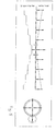
- FIG. 5
- in axial view, the meshing of the damping rotor and the multi-turn counter according to Figures 3 and 4 and the thereby detectable steering angle;
- FIG. 6
- a section through the steering column and by the sensor according to the invention and an enlarged detail; and
- FIG. 7
- a further embodiment of the opposite damping rotors;
- FIG. 8
- the installation location and the installation space of the sensor on the steering column, wherein the combined sensor is indicated according to the invention by its assembled housing parts according to FIG.
In Figur 1a ist ein Gehäuse 9 samt Boden und ein Gehäusedeckel 1 in axialer Richtung der Lenksäule 2a, 6a auseinander gezogen, so dass ein Ausführungsbeispiel des erfindungsgemäßen Kombinationssensors sichtbar wird. In Figur 8 ist der Einbauort dieses Gehäuses 1, 9 an der Lenksäule 2a, 6a genauer dargestellt. Die Lenksäule ist durch eine Eingangswelle 2a und eine Ausgangswelle 6a geteilt. Auf der Ausgangswelle 6a sitzt ein Schneckenrad, das zum Getriebegehäuse gehört. Daneben befindet sich die Stoßstelle 12 der Eingangswelle 2a und der Ausgangswelle 6a, die das Sensorgehäuse 1, 9 durchsetzt. Gemäß Figur 1b kann der Multiturnsensor 7 aus Gründen der Platzersparnis auch auf der Eingangswelle 2a angeordnet sein.In Figure 1a, a
In Figur 6 lässt der axiale Schnitt die Eingangswelle 2a, die Ausgangswelle 6a und einen innen liegenden Torsionsstab 11 erkennen. Die elastische Verdrehung des Torsionsstabs 11 bestimmt die relative Winkeldifferenz der Wellenenden an der Stoßstelle 12 als Funktion des angreifenden, vom Lenkrad her übertragenen Drehmoments. In Figur 6 ist noch ein vergrößerter Ausschnitt des Sensors im Schnitt dargestellt.In FIG. 6, the axial section shows the input shaft 2 a, the output shaft 6 a and an inner torsion bar 11. The elastic rotation of the torsion bar 11 determines the relative angular difference of the shaft ends at the joint 12 as a function of the attacking, transmitted from the steering wheel forth torque. In Figure 6 is still an enlarged section of the sensor shown in section.
Zurückkehrend zu Figur 1 ist mit dem Ende der Eingangswelle 2a ein Dämpfungsrotor 2 verbunden. Mit "Dämpfung" ist fortan die elektrische Wirbelstromdämpfung gemeint, die als Induktivitätsänderung von Messspulen auftritt. Mit dem Ende der Ausgangswelle 6a ist ein entsprechender Dämpfungsrotor 6 verbunden.Returning to FIG. 1, a damping
Mit 5 ist eine Sensorplatine oder ein Sensorträger bezeichnet, der in kreisringförmiger Anordnung mehrere Flachspulen 13 trägt. Der Sensorträger 5 ist gehäusefest (1, 9) montiert und wird von der geteilten Lenksäule 2a, 6a rechtwinklig durchsetzt. In Figur 2 ist die Anordnung von vier Flachspulen 13 in der Aufsicht genauer dargestellt. Es hat sich als zweckmäßig erwiesen, die Trennlinie zwischen je zwei Flachspulen 13 nicht genau in radialer Richtung verlaufen zu lassen. Je nach den Anforderungen an die Genauigkeit wird die Anzahl und Form der Flachspulen definiert.5 with a sensor board or a sensor carrier is called, which carries a plurality of flat coils 13 in an annular arrangement. The
Zurückkehrend zu Figur 1 trägt jeder der Dämpfungsrotoren 2 und 6 ein Betätigungselement 14 in derjenigen Messebene, die den Flachspulen 12 zugewandt ist. Die Betätigungselemente 14 sind beispielsweise dünne Aluminiumplättchen, die auf die Stirnflächen der Dämpfungsrotoren 2 und 6 aufgebracht sind. Sie wirken wie eine Wirbelstrombremse ortsselektiv auf die Flachspulen 13 gemäß Figur 2 ein.Returning to FIG. 1, each of the damping
Die Länge des Betätigungselements 14 beträgt weniger als ¼ des Kreisumfangs, so dass die Wirbelstromdämpfung ortsselektiv jeweils auf zwei der vier Flachspulen 13 gemäß Figur 2 einwirkt. Wichtig für die ortsselektive Arbeitsweise ist, dass das Betätigungselement 14 sich nicht über den gesamten Kreisumfang erstreckt und keine periodisch sich wiederholenden Strukturen aufweist.The length of the actuating element 14 is less than ¼ of the circumference, so that the eddy current damping in a location-selective manner acts on two of the four flat coils 13 according to FIG. Important for the location-selective operation is that the actuating element 14 does not extend over the entire circumference and has no periodically repeating structures.
Die Betätigungselemente 2b und 6b wirken an zwei verschiedenen Stellen auf die kreisbogenförmige Spulenanordnung 13 ein. Insbesondere sind sie in der gleichen Messebene um etwa 180 Grad gegeneinander versetzt. Da die von den Flachpulen 13 erzeugten Signale ständig gemessen werden, stehen ständig mindestens zwei absolute Winkelmesssignale auf dem gesamten Kreisumfang von 360 Grad zur Verfügung. Aus diesen Signalen lassen sich sowohl der Lenkwinkel als auch das Drehmoment durch eine digitale Auswertungsschaltung ermitteln.The actuating elements 2b and 6b act on the circular arc coil arrangement 13 at two different locations. In particular, they are offset by about 180 degrees in the same measurement plane. Since the signals generated by the flat coils 13 are constantly measured, there are always at least two absolute angle measurement signals available over the entire circumference of 360 degrees. From these signals, both the steering angle and the torque can be determined by a digital evaluation circuit.
In dieser Technologie, die den Übergang zu "steer-by-wire" bildet, wird häufig eine Redundanz gefordert, die den Ausfall einzelner Bauelemente ohne weiteres verkraftet. In der Technologie gemäß Figur 1 ist diese Redundanz sehr einfach zu erzielen. Hierzu ist ein weiterer Sensorträger 3 auf der anderen Seite der Stoßstelle 12 vorgesehen, der mit seinen Flachspulen 13b eine weitere Messebene bildet. Die gleichen Dämpfungsrotoren 2 und 6 tragen zu diesem Zweck rückseitig zu den ersten Betätigungselementen 2b und 6b weitere Betätigungselemente 2c und 6c, die in geringem Abstand zu den weiteren Flachspulen 13b in der zweiten Messebene wirksam sind. Aufbau und Funktion der weiteren Trägerplatine 3 sind völlig analog.In this technology, which forms the transition to "steer-by-wire", a redundancy is often required, which easily copes with the failure of individual components. In the technology according to FIG. 1, this redundancy is very easy to achieve. For this purpose, a
Schließlich trägt der Sensoraufbau gemäß Figur 1 der Tatsache Rechnung, dass insbesondere bei Lastkraftwagen der Lenkwinkel den Bereich eines vollen Kreisumfanges von -180 Grad bis +180 Grad überschreiten kann. Hierzu ist ein Multiturn-Zähler 7 zusätzlich in dem Gehäuse 1, 9 angeordnet. In Figur 1 ist der Multiturn-Zähler 7 zusammen mit dem Gehäuseboden 9 axial herausgezogen; im Einbauzustand liegt er in einer Ebene mit dem Dämpfungsrotor der Ausgangswelle 6a oder der Eingangswelle 2a. Dann greifen der Dämpfungsrotor 6 und der Multiturn-Zähler 7 ineinander, wie die Seitenansicht gemäß Figur 5 erkennen lässt. Gemäß Figur 3 trägt der Dämpfungsrotor 6 hierzu an einer äußeren Stelle des Umfangs einen Mitnehmer 15, der eine schrittweise Mitnahme des Malteserrads 7 bewirkt. Im bevorzugten Ausführungsbeispiel hat das Malteserrad 7 auf dem Kreisumfang sieben Mitnahmeelemente 16 verteilt. Der Multiturn-Zähler 7 gibt also eine Anzeige darüber, in welcher von sieben Umdrehungsperioden sich die Lenksäule befindet. In Figur 5 ist dieser absolute Lenkwinkel von 7 mal 360° = -1260° bis +1260° zusammen mit den sieben Zuständen des Multiturn-Zählers 7 grafisch dargestellt.Finally, the sensor structure according to FIG. 1 takes account of the fact that, in particular in the case of trucks, the steering angle can exceed the range of a full circumference of -180 degrees to +180 degrees. For this purpose, a
Zur Auswertung enthält der Multiturn-Zähler 7, der aus dem speziellen, auf den Mitnehmer des Dämpfungsrotors abgestimmten Antriebsrad besteht, z.B. eine Magnettablette. Mit Hilfe der Magnettablette werden die Umdrehungen der Lenksäule dadurch erfasst, dass auf der Sensorplatine 5 z.B. zwei zusätzliche Hall-Sensoren angeordnet sind. Durch die Mechanik des mitgenommenen Malteserrads wird im Vergleich zu heute üblichen, herkömmlichen Zahnrädern eine schnelle Abnutzung sowie eine Geräuschemission verhindert. Denn im Regelfall wird sich das Multiturn-Malteserrad 7 erst ab einem Lenkwinkeleinschlag von ca. +/- 170° und mehr bewegen.For evaluation contains the
In Figur 7 ist alternativ zu Figur 3 in Verbindung mit Figur 1 ein weiteres Ausführungsbeispiel für gegenüber liegende Dämpfungsrotoren dargestellt. In diesem Fall ist die Formgebung der Nasen, an denen sich die Dämpfungselemente befinden, geändert. Für das zweite Dämpfungselement wird nicht mehr die Rückseite der Nase benutzt, die in die zweite Messebene reicht, sondern es wird eine zweite, separate Nase für das andere Dämpfungselement vorgesehen. Im Ergebnis können die Winkeldaten betriebssicher, mit hoher Ortsauflösung und zeitnah an eine zentrale Regel- und Steuereinrichtung des PKW, LKW oder NKW übertragen werden.FIG. 7 shows, as an alternative to FIG. 3 in conjunction with FIG. 1, a further exemplary embodiment for opposed damping rotors. In this case, the shape of the lugs on which the damping elements are changed. For the second damping element is no longer used the back of the nose, which extends into the second measurement plane, but it is provided a second, separate nose for the other damping element. As a result, the angle data can be transmitted reliably, with high spatial resolution and in a timely manner to a central regulating and control device of the car, truck or commercial vehicle.
Claims (14)
Priority Applications (1)
| Application Number | Priority Date | Filing Date | Title |
|---|---|---|---|
| US11/985,097 US7726208B2 (en) | 2006-11-22 | 2007-11-14 | Combined steering angle and torque sensor |
Applications Claiming Priority (1)
| Application Number | Priority Date | Filing Date | Title |
|---|---|---|---|
| DE102006055049A DE102006055049B3 (en) | 2006-11-22 | 2006-11-22 | Combined steering angle and torque sensor |
Publications (2)
| Publication Number | Publication Date |
|---|---|
| EP1925533A1 true EP1925533A1 (en) | 2008-05-28 |
| EP1925533B1 EP1925533B1 (en) | 2009-05-13 |
Family
ID=38776376
Family Applications (1)
| Application Number | Title | Priority Date | Filing Date |
|---|---|---|---|
| EP07010069A Active EP1925533B1 (en) | 2006-11-22 | 2007-05-21 | Combined lock angle and torque sensor |
Country Status (3)
| Country | Link |
|---|---|
| EP (1) | EP1925533B1 (en) |
| AT (1) | ATE431280T1 (en) |
| DE (2) | DE102006055049B3 (en) |
Cited By (7)
| Publication number | Priority date | Publication date | Assignee | Title |
|---|---|---|---|---|
| US20100023219A1 (en) * | 2006-12-20 | 2010-01-28 | Takata-Petri Ag | Optical Steering Angle Sensor For Determining The Absolute Value of The Steering Angle |
| DE102009011352B3 (en) * | 2009-03-05 | 2010-07-15 | Bourns, Inc., Riverside | Torsion angle sensor for measuring torsion angle of two shafts coupled with each other, has torsion bar, by which two shafts are connected with each other, housing and rotational position sensor |
| WO2011141179A1 (en) * | 2010-05-14 | 2011-11-17 | Trw Automotive Gmbh | Sensor assembly for motor vehicle steering systems |
| CN103925870A (en) * | 2014-04-28 | 2014-07-16 | 牛菊香 | Device for remotely measuring operating angle of mechanical dam |
| WO2019145085A1 (en) * | 2018-01-23 | 2019-08-01 | Robert Bosch Gmbh | Steer-by-wire steering device |
| EP3617659A1 (en) * | 2018-08-30 | 2020-03-04 | Integrated Device Technology, Inc. | Fully redundant position sensor |
| EP3657132A1 (en) * | 2018-11-26 | 2020-05-27 | Integrated Device Technology, Inc. | Inductive position sensor for electronic throttle control |
Families Citing this family (2)
| Publication number | Priority date | Publication date | Assignee | Title |
|---|---|---|---|---|
| DE102008008835B4 (en) | 2008-02-13 | 2010-04-22 | Zf Friedrichshafen Ag | Device for determining a torque |
| DE102011081638A1 (en) * | 2011-08-26 | 2013-02-28 | Zf Friedrichshafen Ag | Housing part for a housing of a sensor for a vehicle transmission, housing for a sensor for a vehicle transmission, sensor for a vehicle transmission and method for producing a sensor for a vehicle transmission |
Citations (7)
| Publication number | Priority date | Publication date | Assignee | Title |
|---|---|---|---|---|
| DE4211616A1 (en) * | 1992-04-07 | 1993-10-14 | Bosch Gmbh Robert | Contactless inductive or eddy current rotation angle measurement appts. for IC engine throttle flap positioner - forms interfitting projection and recess on shaft coupler and plastic sleeve with clearance. |
| DE4232994A1 (en) * | 1992-10-01 | 1994-04-07 | A B Elektronik Gmbh | Shaft torsion and rotation angle measuring device - contains two coil arrangements with six annular coils arranged in groups for measurement on interconnected shafts |
| DE19716321C1 (en) | 1997-04-18 | 1998-10-15 | Kostal Leopold Gmbh & Co Kg | Sensor for indexing angle of rotation e.g. of steering column |
| DE19723069C1 (en) * | 1997-06-02 | 1998-10-22 | Siemens Ag | Inclination angle or tilt sensor esp. for use in vehicles for e.g. alarm systems |
| WO1999021747A1 (en) * | 1997-10-29 | 1999-05-06 | Zf Friedrichshafen Ag | Electrically assisted automotive power steering system |
| DE10046660C1 (en) * | 2000-09-20 | 2001-11-22 | Bosch Gmbh Robert | Sensor arrangement for detecting rotation angle of axle or shaft has wobble wheel with defined number of teeth that engages first gear wheel when rotating part turns, sensor fixed to the rotating part |
| DE10065240A1 (en) | 2000-12-27 | 2002-07-11 | Valeo Schalter & Sensoren Gmbh | Steering angle measuring device |
Family Cites Families (6)
| Publication number | Priority date | Publication date | Assignee | Title |
|---|---|---|---|---|
| DE2951148C2 (en) * | 1979-12-19 | 1984-04-19 | Robert Bosch Gmbh, 7000 Stuttgart | Measuring device for an angle of rotation and / or a torque |
| DE3729230A1 (en) * | 1987-09-02 | 1989-03-16 | Bosch Gmbh Robert | MEASURING DEVICE FOR A TURNING ANGLE AND / OR TORQUE |
| DE19941464A1 (en) * | 1999-09-01 | 2001-03-15 | Hella Kg Hueck & Co | Inductive position sensor |
| DE10101174B4 (en) * | 2001-01-12 | 2005-09-29 | Audi Ag | Sensor device for determining a steering angle and a steering torque |
| DE10156238A1 (en) * | 2001-11-15 | 2003-06-05 | Hella Kg Hueck & Co Patente Ma | Inductive angle sensor, especially for a motor vehicle |
| DE102004027954B4 (en) * | 2004-06-08 | 2018-06-14 | HELLA GmbH & Co. KGaA | Inductive protractor, especially for the measurement of torsion angles |
-
2006
- 2006-11-22 DE DE102006055049A patent/DE102006055049B3/en not_active Expired - Fee Related
-
2007
- 2007-05-21 AT AT07010069T patent/ATE431280T1/en not_active IP Right Cessation
- 2007-05-21 EP EP07010069A patent/EP1925533B1/en active Active
- 2007-05-21 DE DE502007000726T patent/DE502007000726D1/en active Active
Patent Citations (7)
| Publication number | Priority date | Publication date | Assignee | Title |
|---|---|---|---|---|
| DE4211616A1 (en) * | 1992-04-07 | 1993-10-14 | Bosch Gmbh Robert | Contactless inductive or eddy current rotation angle measurement appts. for IC engine throttle flap positioner - forms interfitting projection and recess on shaft coupler and plastic sleeve with clearance. |
| DE4232994A1 (en) * | 1992-10-01 | 1994-04-07 | A B Elektronik Gmbh | Shaft torsion and rotation angle measuring device - contains two coil arrangements with six annular coils arranged in groups for measurement on interconnected shafts |
| DE19716321C1 (en) | 1997-04-18 | 1998-10-15 | Kostal Leopold Gmbh & Co Kg | Sensor for indexing angle of rotation e.g. of steering column |
| DE19723069C1 (en) * | 1997-06-02 | 1998-10-22 | Siemens Ag | Inclination angle or tilt sensor esp. for use in vehicles for e.g. alarm systems |
| WO1999021747A1 (en) * | 1997-10-29 | 1999-05-06 | Zf Friedrichshafen Ag | Electrically assisted automotive power steering system |
| DE10046660C1 (en) * | 2000-09-20 | 2001-11-22 | Bosch Gmbh Robert | Sensor arrangement for detecting rotation angle of axle or shaft has wobble wheel with defined number of teeth that engages first gear wheel when rotating part turns, sensor fixed to the rotating part |
| DE10065240A1 (en) | 2000-12-27 | 2002-07-11 | Valeo Schalter & Sensoren Gmbh | Steering angle measuring device |
Cited By (18)
| Publication number | Priority date | Publication date | Assignee | Title |
|---|---|---|---|---|
| US20100023219A1 (en) * | 2006-12-20 | 2010-01-28 | Takata-Petri Ag | Optical Steering Angle Sensor For Determining The Absolute Value of The Steering Angle |
| US8131425B2 (en) * | 2006-12-20 | 2012-03-06 | Takata-Petri Ag | Optical steering angle sensor for determining the absolute value of the steering angle |
| CN101825425B (en) * | 2009-03-05 | 2014-11-26 | 波恩斯公司 | Torsion angle sensor |
| DE102009011352B3 (en) * | 2009-03-05 | 2010-07-15 | Bourns, Inc., Riverside | Torsion angle sensor for measuring torsion angle of two shafts coupled with each other, has torsion bar, by which two shafts are connected with each other, housing and rotational position sensor |
| CN101825425A (en) * | 2009-03-05 | 2010-09-08 | 波恩斯公司 | Torsion angle sensor |
| US9114833B2 (en) | 2010-05-14 | 2015-08-25 | Trw Automotive Gmbh | Sensor assembly for motor vehicle steering systems |
| CN102947167A (en) * | 2010-05-14 | 2013-02-27 | Trw汽车股份有限公司 | Sensor components for automotive steering systems |
| WO2011141179A1 (en) * | 2010-05-14 | 2011-11-17 | Trw Automotive Gmbh | Sensor assembly for motor vehicle steering systems |
| CN102947167B (en) * | 2010-05-14 | 2015-10-21 | Trw汽车股份有限公司 | Sensor components for automotive steering systems |
| CN103925870A (en) * | 2014-04-28 | 2014-07-16 | 牛菊香 | Device for remotely measuring operating angle of mechanical dam |
| CN103925870B (en) * | 2014-04-28 | 2016-04-13 | 牛菊香 | Machinery checkdam operating angle remote measuring unit |
| WO2019145085A1 (en) * | 2018-01-23 | 2019-08-01 | Robert Bosch Gmbh | Steer-by-wire steering device |
| EP3617659A1 (en) * | 2018-08-30 | 2020-03-04 | Integrated Device Technology, Inc. | Fully redundant position sensor |
| US11112274B2 (en) | 2018-08-30 | 2021-09-07 | Integrated Device Technology, Inc. | Fully redundant position sensor |
| US11668589B2 (en) | 2018-08-30 | 2023-06-06 | Integrated Device Technology, Inc. | Fully redundant position sensor |
| EP3657132A1 (en) * | 2018-11-26 | 2020-05-27 | Integrated Device Technology, Inc. | Inductive position sensor for electronic throttle control |
| CN111219530A (en) * | 2018-11-26 | 2020-06-02 | 集成装置技术公司 | Inductive position sensor for electronic throttle control |
| US11680826B2 (en) | 2018-11-26 | 2023-06-20 | Integrated Device Technology, Inc. | Inductive position sensor for electronic throttle control |
Also Published As
| Publication number | Publication date |
|---|---|
| ATE431280T1 (en) | 2009-05-15 |
| EP1925533B1 (en) | 2009-05-13 |
| DE102006055049B3 (en) | 2008-06-12 |
| DE502007000726D1 (en) | 2009-06-25 |
Similar Documents
| Publication | Publication Date | Title |
|---|---|---|
| EP1925533B1 (en) | Combined lock angle and torque sensor | |
| EP2090497B1 (en) | Device for determining a torsion angle | |
| EP1706716B1 (en) | Device for determining a steering angle and a torque that is exerted on a steering shaft | |
| DE4213866B4 (en) | Rotary motion sensor | |
| EP2748053B1 (en) | Combined steering torque-steering angle sensor | |
| EP1478900B1 (en) | Gear mechanism and a rotary encoder equipped with this gear mechanism | |
| EP2607750B1 (en) | Planetary spindle drive | |
| DE102005031086A1 (en) | Sensor arrangement for detecting a difference angle | |
| DE102004023801A1 (en) | Steering angle sensor for use on road vehicle to determine resultant torque applied to steering column uses two relatively rotatable shaft portions and has multi-pole magnet ring and stator holder | |
| DE102017126906A1 (en) | Achsrotations torque sensor | |
| EP0848679B1 (en) | Steering valve | |
| DE102005011196A1 (en) | Steering column torque detecting sensor arrangement for motor vehicle, has magnetic circuit with flux rings designed as ferromagnetic rings, such that sensor unit and wheel are arranged between inner flux ring and outer flux ring | |
| EP3625522B1 (en) | Multiturn angle measuring device | |
| DE102011121842A1 (en) | Device for measuring torque, direction of rotation and Drehverwidigkeit a shaft of a transmission, in particular an output shaft of an azimuth gear of a wind turbine | |
| DE102010018724A1 (en) | Inductive rotation angle sensor | |
| EP1457762B1 (en) | Device for measuring the position, the displacement or the rotational angle of an object | |
| EP1706708B1 (en) | Steering angle sensor | |
| WO2016050382A1 (en) | Combined sensor concept for steering systems of motor vehicles | |
| DE102009023395B4 (en) | Code disc for an encoder | |
| DE102020108982A1 (en) | Sensor arrangement with a fully redundant measuring system for recording the absolute angular position of a steering element | |
| EP2469239B1 (en) | Multi-turn angle measuring device | |
| DE102016124331A1 (en) | Flux guide, torque sensor device and method of making a flux guide | |
| WO2015082512A2 (en) | Hydrodynamic machine having a measuring system | |
| DE102011088997A1 (en) | Planetary roller screwdriver for converting relative rotation between spindle nut and threaded spindle in translator relative displacement, has spindle nut arranged on threaded spindle and planetary rollers arranged over circumference | |
| EP3882596A2 (en) | Measuring arrangement on a rotatable shaft |
Legal Events
| Date | Code | Title | Description |
|---|---|---|---|
| PUAI | Public reference made under article 153(3) epc to a published international application that has entered the european phase |
Free format text: ORIGINAL CODE: 0009012 |
|
| 17P | Request for examination filed |
Effective date: 20070521 |
|
| AK | Designated contracting states |
Kind code of ref document: A1 Designated state(s): AT BE BG CH CY CZ DE DK EE ES FI FR GB GR HU IE IS IT LI LT LU LV MC MT NL PL PT RO SE SI SK TR |
|
| AX | Request for extension of the european patent |
Extension state: AL BA HR MK RS |
|
| GRAP | Despatch of communication of intention to grant a patent |
Free format text: ORIGINAL CODE: EPIDOSNIGR1 |
|
| RIC1 | Information provided on ipc code assigned before grant |
Ipc: G01D 5/20 20060101ALI20081126BHEP Ipc: G01B 7/30 20060101ALI20081126BHEP Ipc: B62D 15/02 20060101ALI20081126BHEP Ipc: B62D 6/10 20060101AFI20081126BHEP |
|
| AKX | Designation fees paid |
Designated state(s): AT BE BG CH CY CZ DE DK EE ES FI FR GB GR HU IE IS IT LI LT LU LV MC MT NL PL PT RO SE SI SK TR |
|
| GRAS | Grant fee paid |
Free format text: ORIGINAL CODE: EPIDOSNIGR3 |
|
| GRAA | (expected) grant |
Free format text: ORIGINAL CODE: 0009210 |
|
| AK | Designated contracting states |
Kind code of ref document: B1 Designated state(s): AT BE BG CH CY CZ DE DK EE ES FI FR GB GR HU IE IS IT LI LT LU LV MC MT NL PL PT RO SE SI SK TR |
|
| REG | Reference to a national code |
Ref country code: GB Ref legal event code: FG4D Free format text: NOT ENGLISH |
|
| REG | Reference to a national code |
Ref country code: CH Ref legal event code: EP |
|
| REG | Reference to a national code |
Ref country code: IE Ref legal event code: FG4D |
|
| REF | Corresponds to: |
Ref document number: 502007000726 Country of ref document: DE Date of ref document: 20090625 Kind code of ref document: P |
|
| RAP2 | Party data changed (patent owner data changed or rights of a patent transferred) |
Owner name: ZF FRIEDRICHSHAFEN AG |
|
| NLT2 | Nl: modifications (of names), taken from the european patent patent bulletin |
Owner name: ZF FRIEDRICHSHAFEN AG Effective date: 20090715 |
|
| REG | Reference to a national code |
Ref country code: SE Ref legal event code: TRGR |
|
| PG25 | Lapsed in a contracting state [announced via postgrant information from national office to epo] |
Ref country code: FI Free format text: LAPSE BECAUSE OF FAILURE TO SUBMIT A TRANSLATION OF THE DESCRIPTION OR TO PAY THE FEE WITHIN THE PRESCRIBED TIME-LIMIT Effective date: 20090513 Ref country code: PT Free format text: LAPSE BECAUSE OF FAILURE TO SUBMIT A TRANSLATION OF THE DESCRIPTION OR TO PAY THE FEE WITHIN THE PRESCRIBED TIME-LIMIT Effective date: 20090913 Ref country code: LT Free format text: LAPSE BECAUSE OF FAILURE TO SUBMIT A TRANSLATION OF THE DESCRIPTION OR TO PAY THE FEE WITHIN THE PRESCRIBED TIME-LIMIT Effective date: 20090513 Ref country code: ES Free format text: LAPSE BECAUSE OF FAILURE TO SUBMIT A TRANSLATION OF THE DESCRIPTION OR TO PAY THE FEE WITHIN THE PRESCRIBED TIME-LIMIT Effective date: 20090824 |
|
| NLV1 | Nl: lapsed or annulled due to failure to fulfill the requirements of art. 29p and 29m of the patents act | ||
| BERE | Be: lapsed |
Owner name: CHERRY G.M.B.H. Effective date: 20090531 |
|
| PG25 | Lapsed in a contracting state [announced via postgrant information from national office to epo] |
Ref country code: NL Free format text: LAPSE BECAUSE OF FAILURE TO SUBMIT A TRANSLATION OF THE DESCRIPTION OR TO PAY THE FEE WITHIN THE PRESCRIBED TIME-LIMIT Effective date: 20090513 Ref country code: SI Free format text: LAPSE BECAUSE OF FAILURE TO SUBMIT A TRANSLATION OF THE DESCRIPTION OR TO PAY THE FEE WITHIN THE PRESCRIBED TIME-LIMIT Effective date: 20090513 Ref country code: PL Free format text: LAPSE BECAUSE OF FAILURE TO SUBMIT A TRANSLATION OF THE DESCRIPTION OR TO PAY THE FEE WITHIN THE PRESCRIBED TIME-LIMIT Effective date: 20090513 Ref country code: LV Free format text: LAPSE BECAUSE OF FAILURE TO SUBMIT A TRANSLATION OF THE DESCRIPTION OR TO PAY THE FEE WITHIN THE PRESCRIBED TIME-LIMIT Effective date: 20090513 Ref country code: IS Free format text: LAPSE BECAUSE OF FAILURE TO SUBMIT A TRANSLATION OF THE DESCRIPTION OR TO PAY THE FEE WITHIN THE PRESCRIBED TIME-LIMIT Effective date: 20090913 |
|
| REG | Reference to a national code |
Ref country code: IE Ref legal event code: FD4D |
|
| PG25 | Lapsed in a contracting state [announced via postgrant information from national office to epo] |
Ref country code: MC Free format text: LAPSE BECAUSE OF NON-PAYMENT OF DUE FEES Effective date: 20090531 |
|
| PG25 | Lapsed in a contracting state [announced via postgrant information from national office to epo] |
Ref country code: DK Free format text: LAPSE BECAUSE OF FAILURE TO SUBMIT A TRANSLATION OF THE DESCRIPTION OR TO PAY THE FEE WITHIN THE PRESCRIBED TIME-LIMIT Effective date: 20090513 Ref country code: CZ Free format text: LAPSE BECAUSE OF FAILURE TO SUBMIT A TRANSLATION OF THE DESCRIPTION OR TO PAY THE FEE WITHIN THE PRESCRIBED TIME-LIMIT Effective date: 20090513 Ref country code: EE Free format text: LAPSE BECAUSE OF FAILURE TO SUBMIT A TRANSLATION OF THE DESCRIPTION OR TO PAY THE FEE WITHIN THE PRESCRIBED TIME-LIMIT Effective date: 20090513 Ref country code: IE Free format text: LAPSE BECAUSE OF FAILURE TO SUBMIT A TRANSLATION OF THE DESCRIPTION OR TO PAY THE FEE WITHIN THE PRESCRIBED TIME-LIMIT Effective date: 20090513 |
|
| PG25 | Lapsed in a contracting state [announced via postgrant information from national office to epo] |
Ref country code: SK Free format text: LAPSE BECAUSE OF FAILURE TO SUBMIT A TRANSLATION OF THE DESCRIPTION OR TO PAY THE FEE WITHIN THE PRESCRIBED TIME-LIMIT Effective date: 20090513 |
|
| PLBE | No opposition filed within time limit |
Free format text: ORIGINAL CODE: 0009261 |
|
| STAA | Information on the status of an ep patent application or granted ep patent |
Free format text: STATUS: NO OPPOSITION FILED WITHIN TIME LIMIT |
|
| PG25 | Lapsed in a contracting state [announced via postgrant information from national office to epo] |
Ref country code: BG Free format text: LAPSE BECAUSE OF FAILURE TO SUBMIT A TRANSLATION OF THE DESCRIPTION OR TO PAY THE FEE WITHIN THE PRESCRIBED TIME-LIMIT Effective date: 20090813 |
|
| 26N | No opposition filed |
Effective date: 20100216 |
|
| PG25 | Lapsed in a contracting state [announced via postgrant information from national office to epo] |
Ref country code: BE Free format text: LAPSE BECAUSE OF NON-PAYMENT OF DUE FEES Effective date: 20090531 |
|
| PG25 | Lapsed in a contracting state [announced via postgrant information from national office to epo] |
Ref country code: AT Free format text: LAPSE BECAUSE OF NON-PAYMENT OF DUE FEES Effective date: 20090521 |
|
| PG25 | Lapsed in a contracting state [announced via postgrant information from national office to epo] |
Ref country code: GR Free format text: LAPSE BECAUSE OF FAILURE TO SUBMIT A TRANSLATION OF THE DESCRIPTION OR TO PAY THE FEE WITHIN THE PRESCRIBED TIME-LIMIT Effective date: 20090814 |
|
| EUG | Se: european patent has lapsed | ||
| REG | Reference to a national code |
Ref country code: FR Ref legal event code: ST Effective date: 20110131 |
|
| PG25 | Lapsed in a contracting state [announced via postgrant information from national office to epo] |
Ref country code: RO Free format text: LAPSE BECAUSE OF FAILURE TO SUBMIT A TRANSLATION OF THE DESCRIPTION OR TO PAY THE FEE WITHIN THE PRESCRIBED TIME-LIMIT Effective date: 20090513 |
|
| PG25 | Lapsed in a contracting state [announced via postgrant information from national office to epo] |
Ref country code: SE Free format text: LAPSE BECAUSE OF NON-PAYMENT OF DUE FEES Effective date: 20100522 |
|
| PG25 | Lapsed in a contracting state [announced via postgrant information from national office to epo] |
Ref country code: LU Free format text: LAPSE BECAUSE OF NON-PAYMENT OF DUE FEES Effective date: 20090521 Ref country code: MT Free format text: LAPSE BECAUSE OF FAILURE TO SUBMIT A TRANSLATION OF THE DESCRIPTION OR TO PAY THE FEE WITHIN THE PRESCRIBED TIME-LIMIT Effective date: 20090513 |
|
| PG25 | Lapsed in a contracting state [announced via postgrant information from national office to epo] |
Ref country code: FR Free format text: LAPSE BECAUSE OF NON-PAYMENT OF DUE FEES Effective date: 20100531 |
|
| PG25 | Lapsed in a contracting state [announced via postgrant information from national office to epo] |
Ref country code: HU Free format text: LAPSE BECAUSE OF FAILURE TO SUBMIT A TRANSLATION OF THE DESCRIPTION OR TO PAY THE FEE WITHIN THE PRESCRIBED TIME-LIMIT Effective date: 20091114 |
|
| PG25 | Lapsed in a contracting state [announced via postgrant information from national office to epo] |
Ref country code: TR Free format text: LAPSE BECAUSE OF FAILURE TO SUBMIT A TRANSLATION OF THE DESCRIPTION OR TO PAY THE FEE WITHIN THE PRESCRIBED TIME-LIMIT Effective date: 20090513 |
|
| PG25 | Lapsed in a contracting state [announced via postgrant information from national office to epo] |
Ref country code: CY Free format text: LAPSE BECAUSE OF FAILURE TO SUBMIT A TRANSLATION OF THE DESCRIPTION OR TO PAY THE FEE WITHIN THE PRESCRIBED TIME-LIMIT Effective date: 20090513 |
|
| PGFP | Annual fee paid to national office [announced via postgrant information from national office to epo] |
Ref country code: IT Payment date: 20100531 Year of fee payment: 4 |
|
| REG | Reference to a national code |
Ref country code: CH Ref legal event code: PL |
|
| GBPC | Gb: european patent ceased through non-payment of renewal fee |
Effective date: 20110521 |
|
| PG25 | Lapsed in a contracting state [announced via postgrant information from national office to epo] |
Ref country code: LI Free format text: LAPSE BECAUSE OF NON-PAYMENT OF DUE FEES Effective date: 20110531 Ref country code: CH Free format text: LAPSE BECAUSE OF NON-PAYMENT OF DUE FEES Effective date: 20110531 |
|
| PG25 | Lapsed in a contracting state [announced via postgrant information from national office to epo] |
Ref country code: GB Free format text: LAPSE BECAUSE OF NON-PAYMENT OF DUE FEES Effective date: 20110521 |
|
| PGFP | Annual fee paid to national office [announced via postgrant information from national office to epo] |
Ref country code: SE Payment date: 20090531 Year of fee payment: 3 |
|
| PGFP | Annual fee paid to national office [announced via postgrant information from national office to epo] |
Ref country code: FR Payment date: 20090601 Year of fee payment: 3 |
|
| PGFP | Annual fee paid to national office [announced via postgrant information from national office to epo] |
Ref country code: DE Payment date: 20230331 Year of fee payment: 17 |
|
| REG | Reference to a national code |
Ref country code: DE Ref legal event code: R119 Ref document number: 502007000726 Country of ref document: DE |
|
| PG25 | Lapsed in a contracting state [announced via postgrant information from national office to epo] |
Ref country code: DE Free format text: LAPSE BECAUSE OF NON-PAYMENT OF DUE FEES Effective date: 20241203 |