EP1923348A1 - Container Handling System - Google Patents
Container Handling System Download PDFInfo
- Publication number
- EP1923348A1 EP1923348A1 EP08102005A EP08102005A EP1923348A1 EP 1923348 A1 EP1923348 A1 EP 1923348A1 EP 08102005 A EP08102005 A EP 08102005A EP 08102005 A EP08102005 A EP 08102005A EP 1923348 A1 EP1923348 A1 EP 1923348A1
- Authority
- EP
- European Patent Office
- Prior art keywords
- container
- projection
- container body
- vacuum
- processing
- Prior art date
- Legal status (The legal status is an assumption and is not a legal conclusion. Google has not performed a legal analysis and makes no representation as to the accuracy of the status listed.)
- Withdrawn
Links
Images


Classifications
-
- B—PERFORMING OPERATIONS; TRANSPORTING
- B65—CONVEYING; PACKING; STORING; HANDLING THIN OR FILAMENTARY MATERIAL
- B65B—MACHINES, APPARATUS OR DEVICES FOR, OR METHODS OF, PACKAGING ARTICLES OR MATERIALS; UNPACKING
- B65B21/00—Packaging or unpacking of bottles
- B65B21/02—Packaging or unpacking of bottles in or from preformed containers, e.g. crates
- B65B21/08—Introducing or removing single bottles, or groups of bottles, e.g. for progressive filling or emptying of containers
- B65B21/12—Introducing or removing single bottles, or groups of bottles, e.g. for progressive filling or emptying of containers using grippers engaging bottles, e.g. bottle necks
-
- B—PERFORMING OPERATIONS; TRANSPORTING
- B67—OPENING, CLOSING OR CLEANING BOTTLES, JARS OR SIMILAR CONTAINERS; LIQUID HANDLING
- B67C—CLEANING, FILLING WITH LIQUIDS OR SEMILIQUIDS, OR EMPTYING, OF BOTTLES, JARS, CANS, CASKS, BARRELS, OR SIMILAR CONTAINERS, NOT OTHERWISE PROVIDED FOR; FUNNELS
- B67C3/00—Bottling liquids or semiliquids; Filling jars or cans with liquids or semiliquids using bottling or like apparatus; Filling casks or barrels with liquids or semiliquids
- B67C3/02—Bottling liquids or semiliquids; Filling jars or cans with liquids or semiliquids using bottling or like apparatus
- B67C3/04—Bottling liquids or semiliquids; Filling jars or cans with liquids or semiliquids using bottling or like apparatus without applying pressure
- B67C3/045—Apparatus specially adapted for filling bottles with hot liquids
Definitions
- the present invention relates generally to a container handling system and a process for filling, capping and cooling hot-filled containers with a projection, and more particularly to a system and process for filling, capping and cooling hot-filled, blow-molded containers with a projection that can extend outside the container during the filling process and be inverted inside the container before the filled container is removed from a production line.
- blow-molded containers are usually made of plastic and employ flex panels that reinforce the integrity of the container while accommodating internal changes in pressures and volume in the container as a result of heating and cooling. This is especially true with hot-fillable containers, or containers in which hot products are injected during a filling process, capped and cooled to room temperature thereby allowing the filled product to cool to the ambient room temperature.
- hot-fillable containers or containers in which hot products are injected during a filling process, capped and cooled to room temperature thereby allowing the filled product to cool to the ambient room temperature.
- Such containers are disclosed in U.S. Patent Nos. 6,298,638 , 6,439,413 , and 6,467,639 assigned to Graham Packaging Company, all of which are incorporated by reference herein.
- known hot-filled containers made out of plastic tend to be formed with protruding rib structures that surround panels forming the container. While the protruding rib structures improve the strength of the container that is blow-molded out of plastic, the resultant, lightweight, blow-molded containers with panels and protruding rib structure detract from the desired smooth, sleek look of a glass container. Accordingly, a hot-fillable, blow-molded container and process of filling, capping and cooling the same is needed that more closely simulates a glass container and achieves the smooth outward appearance associated with glass containers.
- hot-filled plastic containers tend to have rectangular panels for vacuum compensation.
- conventional hot-fill containers depending upon the size, may have 6 vacuum or flex panels to take up the resultant vacuum after cooling the hot-filled product with rigid, structural columns or ribs between each vacuum panel.
- cover the protruding rib structures and panels with a paper label to improve the aesthetics or overall appearance of the plastic container. Consequently, in order to provide support for the label, the panels of such containers are provided with additional protruding structures.
- hot-filled containers are provided with more recesses and corners from which hot-filled solid products are not easily removed.
- the label covering the panels with protruding structures traps water inside the recessed panels resulting in spillage of the water after the container is removed from ice. Accordingly, a hot-filled, plastic container with a smoother side surface that is relatively or completely free of structural geometry is desired to overcome the shortcomings of the prior art.
- a three stage system utilizes a simplified, blow-molded container that retains its structural integrity after being hot filled and cooled through conventional food or beverage systems. That is, a simplified container according to the invention is a container with at least a portion of the container side walls being relatively smooth that can be filled with a hot product, such as a liquid or a partly solid product, and retain the requisite strength so that a number of containers can be stacked on top of one another with the resultant stack being sturdy.
- the relatively smooth surface is relatively or completely free of structural geometry, such as the structural ribs, riblets, or vacuum panels.
- the simplified, blow-molded container still retains the features of vacuum packaging and the ability to accommodate internal changes in pressure and volume as a result of heating and cooling.
- the simplified container may employ a single main invertible projection by itself to take up the vacuum; or, the simplified container may have a few main projections that take up the vacuum while still providing a substantial portion of the container to be relatively smooth for label placement, for example.
- a mini vacuum panel to supplement the main invertible projection may be used to complete the removal of the resultant vacuum and finish the look of the cooled container.
- structural ribs between vacuum panels are not necessary in a simplified container where a substantial portion of the container body is relatively smooth.
- a container is blow-molded with an approximately polygonal, circular or oval projection extending, for example, from a base of the container.
- the approximately polygonal, circular or oval projection may project from the shoulders of the container, or from another area of the container. If the projection extends from the base of the container, before the container exits the blow-molding operation, the projection may be inverted inside the container so that the base surface of the blow-molded container is relatively flat so that the container can be easily conveyed on a table top, without toppling.
- the blow-molded container may be picked-up by a robotic arm or the like and placed into a production line conveyor where it is supported by its neck.
- a mechanical operation causes a rod to be inserted in the neck of the container and pushes the inverted projection outside the container to provide for the increased volume necessary to receive a hot-filled product, as well as accommodating variations in pressure due to temperature changes during cooling.
- compressed air or other pressure may be used to push the inverted projection outside of the container.
- the container With the projection extending outside the container, the container is filled with a hot product, capped and moved to the cooling operation. Since the container is supported by its neck during the filling and capping operations, the process according to the invention provides maximum control of the containers while being filled and capped.
- the third stage of the operation may divide the filled and capped containers into different lanes and then the containers may be positioned in a rack or basket before entering the cooler for the cooling of the hot-filled product.
- a robotic arm may lift the filled and capped container with the projection extending from the container into a rack or basket. If the projection extends from the base of the container, the basket or rack is provided with an opening for receiving the projection and or enabling the container to stand upright. The container-filled basket or rack is then conveyed through a cooling system to bring the temperature of the hot-filled container to room temperature.
- the container becomes distorted as a vacuum is created in an area where the once hot product filled a portion of the container.
- the cooled, distorted container needs to be reformed to the aesthetic original container shape. Accordingly, it is now possible to return the containers to the desired aesthetic shape obtained after the cool-down contraction of the product by an activator that pushes against the extending projections while the containers are held in place thereby pushing the projection inside the container in an inverted state.
- This inverted state may be the same inverted state achieved before exiting the blow-molding operation.
- the activator may be a relatively flat piece of material with approximately polygonal or circular projections extending therefrom at intervals corresponding to openings of a basket that receive the container projections.
- the activator may be a panel that can invert projections of a single row of containers in the basket. Or, the activator may have several rows of polygonal or circular projections so that an entire basket of containers with projections can be inverted with one upward motion of the activator. While the preceding embodiment describes an activator for inverting projections extending from the base of a container, other activators for inverting projections extending from the shoulders or other areas of the container are envisioned.
- the activator panel can be made out of heavy plastic, metal or wood. The action of inverting the extending projection absorbs the space of the vacuum created by the cooling operation and provides all the vacuum compensation necessary for the cooled, product-filled container.
- This invention satisfies a long felt need for a plastic, blow-molded container having a smooth outward appearance similar to that of a heavier glass container.
- a system for manufacturing a simplified plastic container that is to be filled with a hot product comprising the steps of blow-molding parison to form a container body, the container body having a neck, a base, a smooth side surface surrounding an interior of the container body and a projection extending from the container; filling the container body with the hot product in a production line; capping the neck of the filled container body with a cap in the next operation of the production line; cooling the container body filled with the hot product; and pushing the projection extending from the cooled container body into the interior of the container body so that the resultant, filled and cooled container body is relatively flat. If the projection extends from a base of the container, this inversion permits conveying of the container body on its base.
- containers C formed in a blow-molding or forming operation may exit the blow-molding operation with a base designed so that the container can stand on its own. That is, a container with a relatively smooth side surrounding its interior may be blow-molded with a projection extending from the base of the smooth sided container, and before the blow-molded container leaves the blow-molding operation, the projection of the base may be inverted inside the interior of the container so that the resultant base surface of the container can easily be conveyed in a table top manner.
- the blow-molded containers may be placed in shipping containers 10 or on pallets with, for example, 24 columns and 20 rows so that each rack carries 480 bottles or containers.
- the inverted blow-molded projection can be designed so that the finish or neck area of a container can securely rest within the inverted blow-molded projection.
- the pallets holding the containers can be stacked for easier transportation to an operation that fills, caps and then cools the filled containers.
- the blow-molded containers may be smooth cylinders on the outside without the vacuum compression panels previously considered necessary on the side of the container, which detracted from the sleek appearance of the container and provided recesses for gathering product or ice water.
- These blow-molded containers are preferably made of plastic, such as a thermoplastic polyester resin, for example PET (polyethylene terephthalate) or polyolefins, such as PP and PE.
- PET polyethylene terephthalate
- polyolefins such as PP and PE.
- Each container is blow-molded and formed with an approximately polygonal, circular or oval projection 12 that extends from its base during the initial blow-mold operation.
- the relatively smooth side surface of the container may taper slightly in the midsection of the container to provide an area to place a label.
- the smooth side surface may not be formed with the slight depressed area if the label is printed on the container, for example.
- the relatively smooth surface may have ornamental features (e.g., textures).
- a container may be formed with a grip panel on a portion of the cylindrical body of the container.
- An invertible projection may be formed at the base of the container. The invertible projection may take up most of the vacuum bringing the cooled hot-filled container to its aesthetic appearance.
- mini or supplemental vacuum panels may be necessary to complete the removal of the vacuum in larger containers. These mini or supplemental vacuum panels may be incorporated in the grip panel or at an area that does not interfere with the positioning of a label.
- Grip panels are disclosed, for example, in U.S. Patents Nos. 6,375,025 ; 5,392,937 ; 6,390,316 ; and 5,598,941 .
- Many of the grip panels disclosed in the prior art may also serve as vacuum relief or flex panels. Utilizing the present invention, it is not necessary for the grip panel to act as a vacuum relief panel and the design may therefore be simplified. That is, the ribbed structure associated with the flex panel may not be necessary, or label panel support ribs may be reduced or eliminated. Persons of ordinary skill in the art will be able to modify or simplify known grip panels for use with the present invention.
- the base of a blow-molded container has an inversion or standing ring 14 adjacent a tapered area of the smooth side surface and inside the inversion ring is a substantially smooth projection 12 that extends approximately from a center of the base.
- the size and shape of the projection 12 depends upon the size and shape of the container that is formed during the blow-molding operation, as well as the contraction properties of the contained product.
- the projection Prior to leaving the blow-molding operation, the projection may be forced inside the container to provide a relatively flat surface at the container's base, or a stable base for the container. This inversion of the projection 12 extending from the base of the blow-molded container may be accomplished by pneumatic or mechanical means.
- containers C can be conveyed singularly to a combining system that combines container holding devices and containers.
- the combining system of FIG. 7 includes a container in-feed 18a and a container holding device in-feed 20. As will be more fully described below, this system may be one way to stabilize containers with projected bottom portions that are unable to be supported by their bottom surfaces alone.
- Container in-feed 18a includes a feed scroll assembly 24, which feeds and spaces the containers at the appropriate spacing for merging containers C into a feed-in wheel 22a.
- Wheel 22a comprises a generally star-shaped wheel, which feeds the containers to a main turret system 30 and includes a stationary or fixed plate 23a that supports the respective containers while containers C are fed to turret system 30, where the containers are matched up with a container holding device H and then deactivated to have a projecting bottom portion.
- container holding devices H are fed in and spaced by a second feed scroll 26, which feeds in and spaces container holding devices H to match the spacing on a second feed-in wheel 28, which also comprises a generally star-shaped wheel.
- Feed-in wheel 28 similarly includes a fixed plate 28a for supporting container holding devices H while they are fed into turret system 30.
- Container holding devices H are fed into main turret system 30 where containers C are placed in container holding devices H, with holding devices H providing a stable bottom surface for processing the containers.
- main turret system 30 rotates in a clock-wise direction to align the respective containers over the container holding devices fed in by star wheel 28.
- Wheels 22a and 28 are driven by a motor 29 ( FIG. 8 ), which is drivingly coupled, for example, by a belt or chain or the like, to gears or sheaves mounted on the respective shafts of wheels 22a and 28.
- Container holding devices H comprise disc-shaped members with a first recess with an upwardly facing opening for receiving the lower end of a container and a second recess with downwardly facing opening, which extends upwardly from the downwardly facing side of the disc-shaped member through to the first recess to form a transverse passage through the disc-shaped member.
- the second recess is smaller in diameter than the first so as to form a shelf in the disc-shaped member on which at least the perimeter of the container can rest.
- the containers can then be activated through the transverse passage formed by the second recess, as will be appreciated more fully in reference to FIGS. 5A-C and 12-13 described below.
- the inverted projection of the blow-molded containers should be pushed back out of the container (deactivated).
- a mechanical operation employing a rod that enters the neck of the blow-molded container and pushes against the inverted projection of the blow-molded container causing the inverted projection to move out and project from the bottom of the base, as shown in Figures 1B , 5C and 12-13 .
- other methods of deploying the inverted projection disposed inside a blow-molded container such as injecting pressurized air into the blow-molded container, may be used to force the inverted projection outside of the container.
- the blow-molded projection is initially inverted inside the container and then, a repositioning operation pushes the inverted projection so that it projects out of the container.
- main turret system 30 includes a central shaft 30a, which supports a container carrier wheel 32, a plurality of radially spaced container actuator assemblies 34 and, further, a plurality of radially spaced container holder actuator assemblies 36 ( FIG. 9 ).
- Actuator assemblies 34 deactivate the containers (extend the inverted projection outside the bottom surface of the container), while actuator assemblies 36 support the container holding devices and containers.
- Shaft 30a is also driven by motor 29, which is coupled to a gear or sheave mounted to shaft 30a by a belt or chain or the like.
- main turret system 30 includes a fixed plate 32a for supporting the containers as they are fed into container carrier wheel 32.
- fixed plate 32a terminates adjacent the feed-in point of the container holding devices so that the containers can be placed or dropped into the container holding devices under the force of gravity, for example.
- Container holding devices H are then supported on a rotating plate 32b, which rotates and conveys container holding devices H to discharge wheel 22b, which thereafter feeds the container holding devices and containers to a conveyor 18b, which conveys the container holding devices and containers to a filling system.
- Rotating plate 32b includes openings or is perforated so that the extendable rods of the actuator assemblies 36, which rotate with the rotating plate, may extend through the rotating plate to raise the container holding devices and containers and feed the container holding devices and containers to a fixed plate or platform 23b for feeding to discharge wheel 22b.
- each actuator assembly 34, 36 is positioned to align with a respective container C and container holding device H.
- Each actuator assembly 34 includes an extendable rod 38 for deactivating containers C, as will be described below.
- Each actuator assembly 36 also includes an extendable rod 40 and a pusher member 42, which supports a container holding device, while a container C is dropped into the container holding device H and, further supports the container holding device H while the container is deactivated by extendable rod 38.
- actuator assembly 34 is actuated to extend its extendable rod 38 so that it extends into the container C and applies a downward force onto the invertible projection (12) of the container to thereby move the projection to an extended position to increase the volume of container C for the hot-filling and post-cooling process that follows ( Fig. 1B ).
- rod 38 is retracted so that the container holding device and container may be conveyed for further processing.
- Discharge wheel 22b is similar driven by motor 29, which is coupled to a gear or sheave mounted on its respective shaft.
- main turret assembly 30 includes an upper cam assembly 50 and a lower cam assembly 52.
- Cam assemblies 50 and 52 comprise annular cam plates that encircle shaft 30a and actuator assemblies 34 and 36. The cam plates provide cam surfaces to actuate the actuator assemblies, as will be more fully described below.
- Upper cam assembly 50 includes upper cam plate 54 and a lower cam plate 56, which define there between a cam surface or groove 58 for guiding the respective extendable rods 38 of actuator assemblies 34.
- lower cam assembly 52 includes a lower cam plate 60 and an upper cam plate 62 which define there between a cam surface or groove 64 for guiding extendable rods 40 of actuator assemblies 36.
- actuator assemblies 34 are mounted in a radial arrangement on main turret system 30 and, further, are rotatably mounted such that actuator assemblies 34 rotate with shaft 30a and container holder wheel 32. In addition, actuator assemblies 34 may rotate in a manner to be synchronized with the in-feed of containers C. As each of the respective actuator assemblies 34 is rotated about main turret system 30 with a respective container, the cam follower is guided by groove 58 of cam assembly 50, thereby raising and lowering extendable member 38 to deactivate the containers, as previously noted, after the containers are loaded into the container holding devices.
- the containers according to the invention may be supported at the neck of each container during the filling and capping operations to provide maximum control of the container processes. This may be achieved by rails R, which support the neck of the container, and a traditional cleat and chain drive, or any other known like-conveying modes for moving the containers along the rails R of the production line.
- the extendable projection 12 may be positioned outside the container C by an actuator as described above.
- the process of repositioning the projection outside of the container preferably should occur right before the filling of the hot product into the container.
- the neck of a container would be sufficiently supported by rails so that the repositioning operation could force or pop the inverted base outside of the container without causing the container to fall off the rail conveyor system.
- the container with an extended projection, still supported by its neck may be moved by a traditional neck rail drive to the filling and capping operations, as schematically shown in Figure 2 .
- the system for conveying the filled containers may include dividing the single filling and capping rail R into a plurality of rail lanes RL that feed into a shuttle basket B or rack system.
- the continuous batch mode handling of the containers into the cooling baskets or racks provides total control of the containers/package throughout the cooling cycle.
- baskets or racks are mechanically fed into a lane where the basket or rack receives hot-filled containers with the extending projections from each of the plurality of rail lanes, until the basket is full. After the basket or rack is full of filled containers, it is moved for example, perpendicularly away from the direction of basket or rack feed toward a cooler.
- the shuttle basket or rack system may be driven through a traditional container cooler via a cleat and chain drive, for example.
- the basket may have a gate, which swings down from its upward position in order to allow containers C with the extending projection 12 to enter the basket.
- the rail lanes and basket may be controlled in a sequence to fill the basket or rack with containers.
- the basket or rack would have a plurality of openings for receiving respective projections of the hot-filled containers.
- Either robotic arms and/or the rail lanes would lift a row of hot-filled containers with extending projections over the gate and into respective openings of the basket.
- the basket would move away from its initial fed position exposing another row of openings for receiving hot-filled containers and then that row would be filled with the containers with the extending projections. This process would continue so that the entire basket could receive hot-filled containers.
- the handling of the filled and capped containers with extending projections would also be sequenced so that there would be room underneath the rail lanes to feed the basket or rail.
- the basket could be positioned initially so that a container fed down each rail lane could be lifted into a respective opening of the basket.
- the basket would move to the left, as shown in Figure 3B , and then the next row of containers would be fed down each rail lane and then lifted into the second row openings of the basket or rail.
- the basket or racks could be fed into their position and a robotic arm of the rail lanes could pick up each container and place the same in a respective opening of the basket or rack.
- the handling system provides lane control to align the containers before they are placed in the basket or rack system.
- Figure 4 illustrates how a shuttle basket B or rack system may travel through a traditional cooler, which may have ambient air or coolant blowing against the hot-filled containers to cool their contents to room temperature.
- each shuttle basket or rack enters an activation operation, which reforms the containers from the induced vacuum caused by the cooled down contraction of the product within the containers to aesthetic containers.
- the basket or racks provide location and control of the containers during the activation step at the end of the cooling cycle.
- the activation operation is achieved by placing a panel P with a number of projections corresponding to the projections extending from the containers underneath a container-filled basket B or rack.
- the panel and projections may rest underneath a single row or column of the containers in the basket or rack. Or, the panel and associated projections may be larger extending over two or more row or columns.
- An arm or cover (not shown) is placed over the containers to be activated. Then, the panel is moved upward towards the projections with sufficient force to push the projections back to their inverted position inside a respective container, like a traditional push-up. Thus, the extending projection is moved back inside the container body or re-inverted inside the container.
- the arm or cover placed over the containers holds the containers in place when the force of the activator panel is applied against the containers. It is envisioned that a panel the size of the basket or rack and with respective projections that extend to each of the openings of the basket or rack could invert the projecting base of the container inside each opening in the basket or rack, if the force applied to the panel is sufficient to pop the projecting bases back into the container.
- the activation step would occur at the end of the cooling cycle and would absorb or counter the vacuum created during the cooling of the hot product.
- the containers may be unloaded from the basket or racks that shuttle the containers through the cooler.
- a robotic arm RA may lift the containers at their capped neck vertically upwards and then out of the basket B or rack.
- the containers with the inverted bases would then be released from the robotic arm and sent down another conveying line like a normally filled bottle or container.
- the conveying line could be an in-line rail belt or could be an in-line conveying system using air to control the movement of the containers.
- the conveying line may feed the containers to a labeling operation and then to a packaging operation where the containers are loaded into cases for shipping to a grocery store or the like.
- containers would continue along the production line from the filling station, the capping station and through a cooling station. That is, instead of queuing up the containers for placement in a basket or rack for the cooling operation, each container would move along a production conveyor line. After each container passed through a cooling station, an activator would force the projecting base into the interior of the container. In a similar alternative embodiment where containers are individually passed through the cooling station, the cooled containers are then re-inverted as previously described. Then, the activated containers could be placed in conventional baskets or racks.
- one system for singularly activating containers C includes a feed-in scroll assembly 84, which feeds and, further, spaces the respective container holding devices and their containers at a spacing appropriate for feeding into a feed-in wheel 86.
- Feed-in wheel 86 is of similar construction to wheel 22b and includes a generally star-shaped wheel that feeds-in the container holders and containers to turret assembly 88.
- Turret assembly 88 is of similar construction to turret assembly 30 and includes a container holder wheel 90 for guiding and moving container holding devices H and containers C in a circular path and, further, a plurality of actuator assemblies 104 and 106 for removing the containers from the container holders and for activating the respective containers, as will be more fully described below.
- the holders are discharged by a discharge wheel 92 to conveyor 94 and the containers are discharged by a discharge wheel 96 to a conveyor 98 for further processing.
- Wheels 86, 92, and 96 may be driven by a common motor, which is drivingly coupled to gears or sheaves mounted to the respective shafts of wheels 86, 92, and 96.
- turret assembly 88 is of similar construction to turret assembly 30 and includes container holder wheel 90, upper and lower cam assemblies 100 and 102, respectively, a plurality of actuator assemblies 104 for griping the containers, and a plurality of actuator assemblies 106 for activating the containers.
- turret system 88 includes a support plate 107, which supports the container holders and containers as they are moved by turret system 88.
- container holder wheel 90, actuator assemblies 104, actuator assemblies 106, and plate 107 are commonly mounted to shaft 88a so that they rotate in unison.
- Shaft 88a is similarly driven by the common motor, which is drivingly coupled to a gear or sheave mounted on shaft 88a.
- each actuator assembly 104 includes actuator assembly 34 and a container gripper 108 that is mounted to the extendable rod 38 of actuator assembly 34.
- grippers 108 are, therefore, extended or retracted with the extension or retraction of extendable rods 38, which is controlled by upper cam assembly 100.
- upper cam assembly 100 includes an upper plate 110 and a lower plate 112, which define therebetween a cam surface or recess 114, which guides guide members 72 of actuator assemblies 104 to thereby extend and retract extendable rods 38 and in turn to extend and retract container grippers 108.
- a respective gripper 108 is lowered onto a respective container by its respective extendable rod 38.
- actuator assemblies 106 are then actuated to extend their respective extendable rods 116, which extend through plate 107 and holders H, to apply a compressive force onto the invertible projections of the containers to move the projections to their recessed or retracted positions to thereby activate the containers.
- the upward force generated by extendable rod 116 is counteracted by the downward force of a gripper 108 on container C.
- each actuator assembly 106 is of similar construction to actuator assemblies 34 and 36 and includes a housing 120, which supports extendable rod 116. Similar to the extendable rods of actuator assemblies 34 and 36, extendable rod 116 includes mounted thereto a guide 122, which engages the cam surface or recess 124 of lower cam assembly 102. In this manner, guide member 122 extends and retracts extendable rod 116 as it follows cam surface 124 through turret assembly 88.
- extendable rod 116 when extended, it passes through the base of container holding device H to extend and contact the lower surface of container C and, further, to apply a force sufficient to compress or move the invertible projection its retracted position so that container C can again resume its geometrically stable configuration for normal handling or processing.
- the physics of manipulating the activation panel P or extendable rod 116 is a calculated science recognizing 1) Headspace in a container; 2)Product density in a hot-filled container; 3) Thermal differences from the fill temperature through the cooler temperature through the ambient storage temperature and finally the refrigerated temperature; and 4) Water vapor transmission. By recognizing all of these factors, the size and travel of the activation panel P or extendable rod 116 is calculated so as to achieve predictable and repeatable results. With the vacuum removed from the hot-filled container, the container can be light-weighted because the need to add weight to resist a vacuum or to build vacuum panels is no longer necessary. Weight reduction of a container can be anticipated to be approximately 10%.
Landscapes
- Engineering & Computer Science (AREA)
- Mechanical Engineering (AREA)
- Containers Having Bodies Formed In One Piece (AREA)
- Filling Of Jars Or Cans And Processes For Cleaning And Sealing Jars (AREA)
Abstract

Description
- The present invention relates generally to a container handling system and a process for filling, capping and cooling hot-filled containers with a projection, and more particularly to a system and process for filling, capping and cooling hot-filled, blow-molded containers with a projection that can extend outside the container during the filling process and be inverted inside the container before the filled container is removed from a production line.
- Known blow-molded containers are usually made of plastic and employ flex panels that reinforce the integrity of the container while accommodating internal changes in pressures and volume in the container as a result of heating and cooling. This is especially true with hot-fillable containers, or containers in which hot products are injected during a filling process, capped and cooled to room temperature thereby allowing the filled product to cool to the ambient room temperature. Such containers are disclosed in
U.S. Patent Nos. 6,298,638 ,6,439,413 , and6,467,639 assigned to Graham Packaging Company, all of which are incorporated by reference herein. - In order to obtain the necessary strength associated with glass containers, known hot-filled containers made out of plastic tend to be formed with protruding rib structures that surround panels forming the container. While the protruding rib structures improve the strength of the container that is blow-molded out of plastic, the resultant, lightweight, blow-molded containers with panels and protruding rib structure detract from the desired smooth, sleek look of a glass container. Accordingly, a hot-fillable, blow-molded container and process of filling, capping and cooling the same is needed that more closely simulates a glass container and achieves the smooth outward appearance associated with glass containers.
- In addition to having protruding rib structures for strength, known hot-filled plastic containers tend to have rectangular panels for vacuum compensation. For example, conventional hot-fill containers, depending upon the size, may have 6 vacuum or flex panels to take up the resultant vacuum after cooling the hot-filled product with rigid, structural columns or ribs between each vacuum panel. It is known in the art to cover the protruding rib structures and panels with a paper label to improve the aesthetics or overall appearance of the plastic container. Consequently, in order to provide support for the label, the panels of such containers are provided with additional protruding structures. Thus, hot-filled containers are provided with more recesses and corners from which hot-filled solid products are not easily removed. Or, if the hot-filled product is subsequently chilled by placing the container in ice, the label covering the panels with protruding structures traps water inside the recessed panels resulting in spillage of the water after the container is removed from ice. Accordingly, a hot-filled, plastic container with a smoother side surface that is relatively or completely free of structural geometry is desired to overcome the shortcomings of the prior art.
- A three stage system utilizes a simplified, blow-molded container that retains its structural integrity after being hot filled and cooled through conventional food or beverage systems. That is, a simplified container according to the invention is a container with at least a portion of the container side walls being relatively smooth that can be filled with a hot product, such as a liquid or a partly solid product, and retain the requisite strength so that a number of containers can be stacked on top of one another with the resultant stack being sturdy. The relatively smooth surface is relatively or completely free of structural geometry, such as the structural ribs, riblets, or vacuum panels. In addition, the simplified, blow-molded container still retains the features of vacuum packaging and the ability to accommodate internal changes in pressure and volume as a result of heating and cooling. That is, the simplified container may employ a single main invertible projection by itself to take up the vacuum; or, the simplified container may have a few main projections that take up the vacuum while still providing a substantial portion of the container to be relatively smooth for label placement, for example. Alternatively, depending upon the size of the container, a mini vacuum panel to supplement the main invertible projection may be used to complete the removal of the resultant vacuum and finish the look of the cooled container. Unlike conventional containers, structural ribs between vacuum panels are not necessary in a simplified container where a substantial portion of the container body is relatively smooth.
- Initially, a container is blow-molded with an approximately polygonal, circular or oval projection extending, for example, from a base of the container. The approximately polygonal, circular or oval projection may project from the shoulders of the container, or from another area of the container. If the projection extends from the base of the container, before the container exits the blow-molding operation, the projection may be inverted inside the container so that the base surface of the blow-molded container is relatively flat so that the container can be easily conveyed on a table top, without toppling.
- In the next stage, the blow-molded container may be picked-up by a robotic arm or the like and placed into a production line conveyor where it is supported by its neck. A mechanical operation causes a rod to be inserted in the neck of the container and pushes the inverted projection outside the container to provide for the increased volume necessary to receive a hot-filled product, as well as accommodating variations in pressure due to temperature changes during cooling. Alternatively, compressed air or other pressure may be used to push the inverted projection outside of the container. With the projection extending outside the container, the container is filled with a hot product, capped and moved to the cooling operation. Since the container is supported by its neck during the filling and capping operations, the process according to the invention provides maximum control of the containers while being filled and capped.
- The third stage of the operation may divide the filled and capped containers into different lanes and then the containers may be positioned in a rack or basket before entering the cooler for the cooling of the hot-filled product. It is envisioned that a robotic arm may lift the filled and capped container with the projection extending from the container into a rack or basket. If the projection extends from the base of the container, the basket or rack is provided with an opening for receiving the projection and or enabling the container to stand upright. The container-filled basket or rack is then conveyed through a cooling system to bring the temperature of the hot-filled container to room temperature.
- As the hot-filled product in the container is cooled to room temperature, the container becomes distorted as a vacuum is created in an area where the once hot product filled a portion of the container. Thus, there is no longer a need for the increased volume obtained by the projection extending from the container. In addition, the cooled, distorted container needs to be reformed to the aesthetic original container shape. Accordingly, it is now possible to return the containers to the desired aesthetic shape obtained after the cool-down contraction of the product by an activator that pushes against the extending projections while the containers are held in place thereby pushing the projection inside the container in an inverted state. This inverted state may be the same inverted state achieved before exiting the blow-molding operation.
- The activator, according to one embodiment of the invention, may be a relatively flat piece of material with approximately polygonal or circular projections extending therefrom at intervals corresponding to openings of a basket that receive the container projections. The activator may be a panel that can invert projections of a single row of containers in the basket. Or, the activator may have several rows of polygonal or circular projections so that an entire basket of containers with projections can be inverted with one upward motion of the activator. While the preceding embodiment describes an activator for inverting projections extending from the base of a container, other activators for inverting projections extending from the shoulders or other areas of the container are envisioned. The activator panel can be made out of heavy plastic, metal or wood. The action of inverting the extending projection absorbs the space of the vacuum created by the cooling operation and provides all the vacuum compensation necessary for the cooled, product-filled container.
- This invention satisfies a long felt need for a plastic, blow-molded container having a smooth outward appearance similar to that of a heavier glass container.
- A system for manufacturing a simplified plastic container that is to be filled with a hot product, comprising the steps of blow-molding parison to form a container body, the container body having a neck, a base, a smooth side surface surrounding an interior of the container body and a projection extending from the container; filling the container body with the hot product in a production line; capping the neck of the filled container body with a cap in the next operation of the production line; cooling the container body filled with the hot product; and pushing the projection extending from the cooled container body into the interior of the container body so that the resultant, filled and cooled container body is relatively flat. If the projection extends from a base of the container, this inversion permits conveying of the container body on its base.
- Further objectives and advantages, as well as the structure and function of preferred embodiments will become apparent from a consideration of the description, drawings, and examples.
- The foregoing and other features and advantages of the invention will be apparent from the following, more particular description of a preferred embodiment of the invention, as illustrated in the accompanying drawings wherein like reference numbers generally indicate identical, functionally similar, and/or structurally similar elements.
-
FIG. 1 A schematically depicts containers according to the invention leaving the blow-molding operation; -
FIG. 1B illustrates an embodiment of a plastic, blow-molded container with a smooth surface according to the invention; -
FIG. 2 schematically depicts containers being filled and capped; -
FIGS. 3A and B depict exemplary channeling of containers into baskets or racks according to the present invention for the cooling operation; -
FIG. 4 depicts an exemplary flow of racked containers in a cooler according to the present invention; -
FIGS. 5 A-C schematically illustrate one embodiment of an activation operation according to the invention; -
FIG. 6 schematically depicts an exemplary embodiment of containers exiting the cooling operation, after the activation operation according to the present invention; -
FIG. 7 is a schematic plan view of an exemplary handling system that combines single containers with a container holding device according to the invention; -
FIG. 8 is a front side elevation view of the handling system ofFIG. 7 ; -
FIG. 9 is an unfolded elevation view of a section of the combining portion of the handling system ofFIG. 8 illustrating the movement of the actuators; -
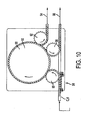
FIG. 10 is a schematic plan view of a second embodiment of an activation portion of the handling system of the present invention; -
FIG. 11 is a detailed plan view of the activation portion of the handling system ofFIG. 10 ; -
FIG. 12 is an unfolded elevation view of a section of the activation portion ofFIG. 10 illustrating the activation of the container and the removal of the container from the container holding device; -
FIG. 13 is an enlarged view of a section of the activation portion ofFIG. 12 ; and -
FIG. 14 is an enlarged view of the container holder removal section ofFIG. 12 . - Embodiments of the invention are discussed in detail below. In describing embodiments, specific terminology is employed for the sake of clarity. However, the invention is not intended to be limited to the specific terminology so selected. While specific exemplary embodiments are discussed, it should be understood that this is done for illustration purposes only. A person skilled in the relevant art will recognize that other components and configurations can be used without parting from the spirit and scope of the invention. All references cited herein are incorporated by reference as if each had been individually incorporated.
- As shown schematically in
Figure 1A , containers C formed in a blow-molding or forming operation may exit the blow-molding operation with a base designed so that the container can stand on its own. That is, a container with a relatively smooth side surrounding its interior may be blow-molded with a projection extending from the base of the smooth sided container, and before the blow-molded container leaves the blow-molding operation, the projection of the base may be inverted inside the interior of the container so that the resultant base surface of the container can easily be conveyed in a table top manner. As shown inFigure 1 , the blow-molded containers may be placed inshipping containers 10 or on pallets with, for example, 24 columns and 20 rows so that each rack carries 480 bottles or containers. The inverted blow-molded projection can be designed so that the finish or neck area of a container can securely rest within the inverted blow-molded projection. As a result, the pallets holding the containers can be stacked for easier transportation to an operation that fills, caps and then cools the filled containers. - As shown in
Figure 1B , the blow-molded containers may be smooth cylinders on the outside without the vacuum compression panels previously considered necessary on the side of the container, which detracted from the sleek appearance of the container and provided recesses for gathering product or ice water. These blow-molded containers are preferably made of plastic, such as a thermoplastic polyester resin, for example PET (polyethylene terephthalate) or polyolefins, such as PP and PE. Each container is blow-molded and formed with an approximately polygonal, circular oroval projection 12 that extends from its base during the initial blow-mold operation. In the exemplary embodiment, the relatively smooth side surface of the container may taper slightly in the midsection of the container to provide an area to place a label. In another embodiment of such a blow-molded container, the smooth side surface may not be formed with the slight depressed area if the label is printed on the container, for example. Alternatively, the relatively smooth surface may have ornamental features (e.g., textures). - In the case of larger containers (e.g., 64oz.), a container may be formed with a grip panel on a portion of the cylindrical body of the container. Thus, Applicants envision simplified containers where a substantial portion of the cylindrical body is relatively or completely free of structural geometry. An invertible projection may be formed at the base of the container. The invertible projection may take up most of the vacuum bringing the cooled hot-filled container to its aesthetic appearance. It is envisioned that mini or supplemental vacuum panels may be necessary to complete the removal of the vacuum in larger containers. These mini or supplemental vacuum panels may be incorporated in the grip panel or at an area that does not interfere with the positioning of a label.
- Grip panels are disclosed, for example, in
U.S. Patents Nos. 6,375,025 ;5,392,937 ;6,390,316 ; and5,598,941 . Many of the grip panels disclosed in the prior art may also serve as vacuum relief or flex panels. Utilizing the present invention, it is not necessary for the grip panel to act as a vacuum relief panel and the design may therefore be simplified. That is, the ribbed structure associated with the flex panel may not be necessary, or label panel support ribs may be reduced or eliminated. Persons of ordinary skill in the art will be able to modify or simplify known grip panels for use with the present invention. - The base of a blow-molded container, according to one embodiment of the invention, has an inversion or standing
ring 14 adjacent a tapered area of the smooth side surface and inside the inversion ring is a substantiallysmooth projection 12 that extends approximately from a center of the base. The size and shape of theprojection 12 depends upon the size and shape of the container that is formed during the blow-molding operation, as well as the contraction properties of the contained product. Prior to leaving the blow-molding operation, the projection may be forced inside the container to provide a relatively flat surface at the container's base, or a stable base for the container. This inversion of theprojection 12 extending from the base of the blow-molded container may be accomplished by pneumatic or mechanical means. - In this manner, as best seen in
FIG. 7 , containers C can be conveyed singularly to a combining system that combines container holding devices and containers. The combining system ofFIG. 7 includes a container in-feed 18a and a container holding device in-feed 20. As will be more fully described below, this system may be one way to stabilize containers with projected bottom portions that are unable to be supported by their bottom surfaces alone. Container in-feed 18a includes afeed scroll assembly 24, which feeds and spaces the containers at the appropriate spacing for merging containers C into a feed-inwheel 22a.Wheel 22a comprises a generally star-shaped wheel, which feeds the containers to amain turret system 30 and includes a stationary or fixedplate 23a that supports the respective containers while containers C are fed toturret system 30, where the containers are matched up with a container holding device H and then deactivated to have a projecting bottom portion. - Similarly, container holding devices H are fed in and spaced by a
second feed scroll 26, which feeds in and spaces container holding devices H to match the spacing on a second feed-inwheel 28, which also comprises a generally star-shaped wheel. Feed-inwheel 28 similarly includes a fixedplate 28a for supporting container holding devices H while they are fed intoturret system 30. Container holding devices H are fed intomain turret system 30 where containers C are placed in container holding devices H, with holding devices H providing a stable bottom surface for processing the containers. In the illustrated embodiment,main turret system 30 rotates in a clock-wise direction to align the respective containers over the container holding devices fed in bystar wheel 28. However, it should be understood that the direction of rotation may be changed.Wheels FIG. 8 ), which is drivingly coupled, for example, by a belt or chain or the like, to gears or sheaves mounted on the respective shafts ofwheels - Container holding devices H comprise disc-shaped members with a first recess with an upwardly facing opening for receiving the lower end of a container and a second recess with downwardly facing opening, which extends upwardly from the downwardly facing side of the disc-shaped member through to the first recess to form a transverse passage through the disc-shaped member. The second recess is smaller in diameter than the first so as to form a shelf in the disc-shaped member on which at least the perimeter of the container can rest. As noted above, when a container is deactivated, its vacuum panels will be extended or projecting from the bottom surface. The extended or projecting portion is accommodated by the second recess. In addition, the containers can then be activated through the transverse passage formed by the second recess, as will be appreciated more fully in reference to
FIGS. 5A-C and12-13 described below. - In order to provide extra volume and accomodation of pressure changes needed when the containers are filled with a hot product, such as a hot liquid or a partly solid product, the inverted projection of the blow-molded containers should be pushed back out of the container (deactivated). For example, a mechanical operation employing a rod that enters the neck of the blow-molded container and pushes against the inverted projection of the blow-molded container causing the inverted projection to move out and project from the bottom of the base, as shown in
Figures 1B ,5C and12-13 . Alternatively, other methods of deploying the inverted projection disposed inside a blow-molded container, such as injecting pressurized air into the blow-molded container, may be used to force the inverted projection outside of the container. Thus, in this embodiment, the blow-molded projection is initially inverted inside the container and then, a repositioning operation pushes the inverted projection so that it projects out of the container. - Referring to
FIG. 8 ,main turret system 30 includes acentral shaft 30a, which supports acontainer carrier wheel 32, a plurality of radially spacedcontainer actuator assemblies 34 and, further, a plurality of radially spaced container holder actuator assemblies 36 (FIG. 9 ).Actuator assemblies 34 deactivate the containers (extend the inverted projection outside the bottom surface of the container), whileactuator assemblies 36 support the container holding devices and containers.Shaft 30a is also driven bymotor 29, which is coupled to a gear or sheave mounted toshaft 30a by a belt or chain or the like. In addition,main turret system 30 includes a fixedplate 32a for supporting the containers as they are fed intocontainer carrier wheel 32. However, fixedplate 32a terminates adjacent the feed-in point of the container holding devices so that the containers can be placed or dropped into the container holding devices under the force of gravity, for example. Container holding devices H are then supported on arotating plate 32b, which rotates and conveys container holding devices H to dischargewheel 22b, which thereafter feeds the container holding devices and containers to aconveyor 18b, which conveys the container holding devices and containers to a filling system. Rotatingplate 32b includes openings or is perforated so that the extendable rods of theactuator assemblies 36, which rotate with the rotating plate, may extend through the rotating plate to raise the container holding devices and containers and feed the container holding devices and containers to a fixed plate orplatform 23b for feeding to dischargewheel 22b. - As best seen in
FIG. 9 , eachactuator assembly actuator assembly 34 includes anextendable rod 38 for deactivating containers C, as will be described below. Eachactuator assembly 36 also includes anextendable rod 40 and a pusher member 42, which supports a container holding device, while a container C is dropped into the container holding device H and, further supports the container holding device H while the container is deactivated byextendable rod 38. To deactivate a container,actuator assembly 34 is actuated to extend itsextendable rod 38 so that it extends into the container C and applies a downward force onto the invertible projection (12) of the container to thereby move the projection to an extended position to increase the volume of container C for the hot-filling and post-cooling process that follows (Fig. 1B ). Afterrod 38 has fully extended the invertible projection of a container,rod 38 is retracted so that the container holding device and container may be conveyed for further processing. - Again as best seen in
FIG. 9 , whilerod 38 is retracted,extendable rod 40 ofactuator 36 is further extended to raise the container holding device and container to an elevation for placement on fixed plate orplatform 23b ofdischarge wheel 22b.Wheel 22b feeds the container holding device and container to anadjacent conveyor 18b, which conveys the container holding device and container to filling portion 16 of the container processing system.Discharge wheel 22b is similar driven bymotor 29, which is coupled to a gear or sheave mounted on its respective shaft. - Referring again to
FIGS. 8 and9 ,main turret assembly 30 includes anupper cam assembly 50 and alower cam assembly 52.Cam assemblies shaft 30a andactuator assemblies Upper cam assembly 50 includesupper cam plate 54 and alower cam plate 56, which define there between a cam surface or groove 58 for guiding the respectiveextendable rods 38 ofactuator assemblies 34. Similarly,lower cam assembly 52 includes alower cam plate 60 and anupper cam plate 62 which define there between a cam surface or groove 64 for guidingextendable rods 40 ofactuator assemblies 36. Mounted toextendable rod 38 may be a guide member or cam follower, which engages cam groove orsurface 58 ofupper cam assembly 50. As noted previously,actuator assemblies 34 are mounted in a radial arrangement onmain turret system 30 and, further, are rotatably mounted such thatactuator assemblies 34 rotate withshaft 30a andcontainer holder wheel 32. In addition,actuator assemblies 34 may rotate in a manner to be synchronized with the in-feed of containers C. As each of therespective actuator assemblies 34 is rotated aboutmain turret system 30 with a respective container, the cam follower is guided bygroove 58 ofcam assembly 50, thereby raising and loweringextendable member 38 to deactivate the containers, as previously noted, after the containers are loaded into the container holding devices. - If the container holding devices are not used, the containers according to the invention may be supported at the neck of each container during the filling and capping operations to provide maximum control of the container processes. This may be achieved by rails R, which support the neck of the container, and a traditional cleat and chain drive, or any other known like-conveying modes for moving the containers along the rails R of the production line. The
extendable projection 12 may be positioned outside the container C by an actuator as described above. - The process of repositioning the projection outside of the container preferably should occur right before the filling of the hot product into the container. According to one embodiment of the invention, the neck of a container would be sufficiently supported by rails so that the repositioning operation could force or pop the inverted base outside of the container without causing the container to fall off the rail conveyor system. In some instances, it may not be necessary to invert the projection prior to leaving the blow-molding operation and these containers are moved directly to a filling station. The container with an extended projection, still supported by its neck, may be moved by a traditional neck rail drive to the filling and capping operations, as schematically shown in
Figure 2 . - As shown in
Figure 3A , the system for conveying the filled containers may include dividing the single filling and capping rail R into a plurality of rail lanes RL that feed into a shuttle basket B or rack system. The continuous batch mode handling of the containers into the cooling baskets or racks provides total control of the containers/package throughout the cooling cycle. As shown inFigure 3B , baskets or racks are mechanically fed into a lane where the basket or rack receives hot-filled containers with the extending projections from each of the plurality of rail lanes, until the basket is full. After the basket or rack is full of filled containers, it is moved for example, perpendicularly away from the direction of basket or rack feed toward a cooler. The shuttle basket or rack system may be driven through a traditional container cooler via a cleat and chain drive, for example. - In one embodiment, the basket may have a gate, which swings down from its upward position in order to allow containers C with the extending
projection 12 to enter the basket. In that the hot-filled containers have projections extending from their base, the rail lanes and basket may be controlled in a sequence to fill the basket or rack with containers. For example, the basket or rack would have a plurality of openings for receiving respective projections of the hot-filled containers. Either robotic arms and/or the rail lanes would lift a row of hot-filled containers with extending projections over the gate and into respective openings of the basket. The basket would move away from its initial fed position exposing another row of openings for receiving hot-filled containers and then that row would be filled with the containers with the extending projections. This process would continue so that the entire basket could receive hot-filled containers. - The handling of the filled and capped containers with extending projections would also be sequenced so that there would be room underneath the rail lanes to feed the basket or rail. Thus, the basket could be positioned initially so that a container fed down each rail lane could be lifted into a respective opening of the basket. The basket would move to the left, as shown in
Figure 3B , and then the next row of containers would be fed down each rail lane and then lifted into the second row openings of the basket or rail. Alternatively, the basket or racks could be fed into their position and a robotic arm of the rail lanes could pick up each container and place the same in a respective opening of the basket or rack. - After the basket is full of hot-filled containers, the gate would swing upwards and lock onto the side of the basket and then the basket would move toward the cooler C. Thus, according to the invention, the handling system provides lane control to align the containers before they are placed in the basket or rack system.
Figure 4 illustrates how a shuttle basket B or rack system may travel through a traditional cooler, which may have ambient air or coolant blowing against the hot-filled containers to cool their contents to room temperature. - After the containers and their contents have been cooled during the cooling operation, the cooled product has contracted and thus an extra amount of volume exists in these cooled containers. However, the cooling operation also induces a vacuum in each container which distorts each container thereby lessening the amount of volume in the container. Since the projection extending from the base of the container is no longer necessary and a relatively flat base surface is desired, each shuttle basket or rack enters an activation operation, which reforms the containers from the induced vacuum caused by the cooled down contraction of the product within the containers to aesthetic containers. The basket or racks provide location and control of the containers during the activation step at the end of the cooling cycle.
- As schematically shown in
Figures 5A-C , the activation operation is achieved by placing a panel P with a number of projections corresponding to the projections extending from the containers underneath a container-filled basket B or rack. The panel and projections may rest underneath a single row or column of the containers in the basket or rack. Or, the panel and associated projections may be larger extending over two or more row or columns. An arm or cover (not shown) is placed over the containers to be activated. Then, the panel is moved upward towards the projections with sufficient force to push the projections back to their inverted position inside a respective container, like a traditional push-up. Thus, the extending projection is moved back inside the container body or re-inverted inside the container. The arm or cover placed over the containers holds the containers in place when the force of the activator panel is applied against the containers. It is envisioned that a panel the size of the basket or rack and with respective projections that extend to each of the openings of the basket or rack could invert the projecting base of the container inside each opening in the basket or rack, if the force applied to the panel is sufficient to pop the projecting bases back into the container. - In an exemplary embodiment, the activation step would occur at the end of the cooling cycle and would absorb or counter the vacuum created during the cooling of the hot product. Once the base projections have been re-inverted so that each base surface is relatively flat, the containers may be unloaded from the basket or racks that shuttle the containers through the cooler. As schematically shown in
Figure 6 , at the cooling exit, a robotic arm RA may lift the containers at their capped neck vertically upwards and then out of the basket B or rack. The containers with the inverted bases would then be released from the robotic arm and sent down another conveying line like a normally filled bottle or container. The conveying line could be an in-line rail belt or could be an in-line conveying system using air to control the movement of the containers. The conveying line may feed the containers to a labeling operation and then to a packaging operation where the containers are loaded into cases for shipping to a grocery store or the like. - In an alternative operation, it is envisioned that containers would continue along the production line from the filling station, the capping station and through a cooling station. That is, instead of queuing up the containers for placement in a basket or rack for the cooling operation, each container would move along a production conveyor line. After each container passed through a cooling station, an activator would force the projecting base into the interior of the container. In a similar alternative embodiment where containers are individually passed through the cooling station, the cooled containers are then re-inverted as previously described. Then, the activated containers could be placed in conventional baskets or racks.
- Referring to
FIGS. 10 and11 , one system for singularly activating containers C includes a feed-inscroll assembly 84, which feeds and, further, spaces the respective container holding devices and their containers at a spacing appropriate for feeding into a feed-inwheel 86. Feed-inwheel 86 is of similar construction towheel 22b and includes a generally star-shaped wheel that feeds-in the container holders and containers toturret assembly 88.Turret assembly 88 is of similar construction toturret assembly 30 and includes acontainer holder wheel 90 for guiding and moving container holding devices H and containers C in a circular path and, further, a plurality ofactuator assemblies discharge wheel 92 toconveyor 94 and the containers are discharged by adischarge wheel 96 to aconveyor 98 for further processing.Wheels wheels - As previously noted,
turret assembly 88 is of similar construction toturret assembly 30 and includescontainer holder wheel 90, upper andlower cam assemblies actuator assemblies 104 for griping the containers, and a plurality ofactuator assemblies 106 for activating the containers. In addition,turret system 88 includes asupport plate 107, which supports the container holders and containers as they are moved byturret system 88. As best seen inFIG. 11 ,container holder wheel 90,actuator assemblies 104,actuator assemblies 106, andplate 107 are commonly mounted toshaft 88a so that they rotate in unison.Shaft 88a is similarly driven by the common motor, which is drivingly coupled to a gear or sheave mounted onshaft 88a. - Looking at
FIGS 12-14 ,actuator assemblies lower cam assemblies FIG. 12 , eachactuator assembly 104 includesactuator assembly 34 and acontainer gripper 108 that is mounted to theextendable rod 38 ofactuator assembly 34. As would be understood,grippers 108 are, therefore, extended or retracted with the extension or retraction ofextendable rods 38, which is controlled byupper cam assembly 100. - Similar to
upper cam assembly 50,upper cam assembly 100 includes anupper plate 110 and alower plate 112, which define therebetween a cam surface orrecess 114, which guidesguide members 72 ofactuator assemblies 104 to thereby extend and retractextendable rods 38 and in turn to extend and retractcontainer grippers 108. As the containers are conveyed throughturret assembly 88, arespective gripper 108 is lowered onto a respective container by its respectiveextendable rod 38. Once the gripper is positioned on the respective container,actuator assemblies 106 are then actuated to extend their respectiveextendable rods 116, which extend throughplate 107 and holders H, to apply a compressive force onto the invertible projections of the containers to move the projections to their recessed or retracted positions to thereby activate the containers. As would be understood, the upward force generated byextendable rod 116 is counteracted by the downward force of agripper 108 on container C. After the activation of each container is complete, the container then can be removed from the holder by itsrespective gripper 108. - Referring to
FIGS. 12-13 , eachactuator assembly 106 is of similar construction toactuator assemblies housing 120, which supportsextendable rod 116. Similar to the extendable rods ofactuator assemblies extendable rod 116 includes mounted thereto aguide 122, which engages the cam surface orrecess 124 oflower cam assembly 102. In this manner,guide member 122 extends and retractsextendable rod 116 as it followscam surface 124 throughturret assembly 88. As noted previously, whenextendable rod 116 is extended, it passes through the base of container holding device H to extend and contact the lower surface of container C and, further, to apply a force sufficient to compress or move the invertible projection its retracted position so that container C can again resume its geometrically stable configuration for normal handling or processing. - The physics of manipulating the activation panel P or
extendable rod 116 is a calculated science recognizing 1) Headspace in a container; 2)Product density in a hot-filled container; 3) Thermal differences from the fill temperature through the cooler temperature through the ambient storage temperature and finally the refrigerated temperature; and 4) Water vapor transmission. By recognizing all of these factors, the size and travel of the activation panel P orextendable rod 116 is calculated so as to achieve predictable and repeatable results. With the vacuum removed from the hot-filled container, the container can be light-weighted because the need to add weight to resist a vacuum or to build vacuum panels is no longer necessary. Weight reduction of a container can be anticipated to be approximately 10%. - The embodiments illustrated and discussed in this specification are intended only to teach those skilled in the art the best way known to the inventors to make and use the invention. Nothing in this specification should be considered as limiting the scope of the present invention. All examples presented are representative and nonlimiting. The above-described embodiments of the invention may be modified or varied, without departing from the invention, as appreciated by those skilled in the art in light of the above teachings. It is therefore to be understood that, within the scope of the claims and their equivalents, the invention may be practiced otherwise than as specifically described.
Claims (39)
- A method for processing a plastic container (C) with a vacuum panel incorporated into the container body bottom, comprising:filling a container body with a product in a production line of container bodies, the container body having a projection (12) extending from the container body bottom;sealing the filled container body in a subsequent operation of the production line;creating a vacuum in the container; andpushing the projection (12) extending from the cooled container body bottom into the interior of the container body with a first actuator (106), wherein the container body with the projection (12) extending from the container body bottom is supported by its neck during the filling and the sealing.
- The method for processing a plastic container according to claim 1, wherein the product is filled as a hot product, and the method further comprises:dividing the production line of container bodies, after the sealing, into a number of lanes (RL) so that a number of container bodies are formed in lanes for placement in a container holding device (B); andcooling the container body filled with the hot product.
- The method for processing a plastic container according to any of claims 1-2,
wherein the plastic container (C) is picked up by a robotic arm and placed in the container holding device (B) so such that the projection (12) extending from the container body bottom corresponds to an opening in the container holding device (B), and
the cooling includes moving the container holding device (B) filled with container bodies through a cooler to cool the hot product in respective container bodies. - The method for processing a plastic container according to claim 1, wherein the pushing of the projection (12) extending from the body bottom into the interior of the container body includes:positioning an actuator panel (P), which includes the first actuator (106) extending therefrom, underneath a container holding device (B) configured to hold the container such that the first actuator (106) corresponds with the projection (12) of the container body bottom, the projection also corresponding to a respective opening of the container holding device; andmoving the actuator panel (P), which includes the first actuator (106), against the projection (12), thereby forcing the projection (12) into the interior of the container body.
- The method for processing a plastic container according to any of claims 1 and 4, wherein the actuator panel (P) includes a plurality of actuators, including said first actuator (106), each of said plurality of actuators corresponding to one of a plurality of containers each having a projection (12), the method further comprising simultaneously forcing the projections into the interior of respective ones of the plurality of container bodies.
- The method for processing a plastic container according to claim 1, wherein the projection (12) extending from the container body bottom extends downwardly from the container body bottom below a standing ring in a downwardly extending position during the filling; and
after creating the vacuum, pushing the projection (12) up from its downwardly extending position into the interior of the filled and sealed container body with a first actuator (106) to counteract the vacuum. - The method for processing a plastic container according to any of claims 1 and 6, further comprising simultaneously forcing a plurality of projections (12) from a position extending downwardly from respective ones of a plurality of containers below standing rings to a position above the standing rings.
- The method for processing a plastic container according to claim 1, wherein the projection (12) extending from the container body bottom extends below a standing ring to form an extended container body, the method further comprising carrying the sealed and filled extended container down the production line while supporting the sealed and filled container by the standing ring,
wherein said pushing includes pushing the projection (12) above the standing ring into the filled and sealed container body after said carrying. - The method for processing a plastic container according to any of claims 1 and 8, further comprising a plurality of said plastic containers (C), wherein said pushing is done with an actuator panel (P) having a plurality of projections, each projection simultaneously pushing a projection (12) from a different container of said plurality.
- The method for processing a plastic container according to claim 1, further comprising:blow-molding a parison to form the container body with the projection (12) extending from the bottom of the container body, said extending being outwardly;after the forming of the container body in the blow-molding step, inverting the projection (12) to extend inwardly from the container body bottom;after the inverting step, transporting the container body with the projection inverted;after the transporting step, repositioning the projection (12) with an outwardly directed force; andafter the repositioning step, performing said filling the container body with a product.
- The method for processing a plastic container according to any of claims 1 and 10, wherein the container body bottom comprises a single standing ring, the standing ring is substantially planar, the container body is supported by the standing ring resting on a substantially planar surface during the transporting step, and the container body is supported by the standing ring resting on a substantially planar surface after the pushing step.
- The method for processing a plastic container according to claim 1, wherein the vacuum panel is incorporated into the container body bottom radially inside of a standing ring, the method further comprising:feeding the plastic container (C) having an extendable projection (12) extending from the container body bottom; andmoving the projection (12) to an extended position below the standing ring with a second actuator (34), the second actuator (34) including an extendable rod (38),wherein said pushing the projection (12) includes pushing the projection (12) from the extended position below the standing ring to a non-extended position fully within the container body above and radially inside of the standing ring to reduce distortion caused by the vacuum, and
wherein the vacuum is created in the sealed and filled container (C) while the projection (12) is in the extended position below the standing ring. - The method for processing a plastic container according to any of claims 1-12, wherein the container has sidewalls, the sidewalls consisting of a first portion and a second portion, the first portion being free of any vacuum panels, and the second portion consisting of a grip panel.
- The method for processing a plastic container according to any of claims 1-13, wherein the grip panel includes a vacuum panel.
- The method for processing a plastic container according to any of claims 1-14, wherein the grip panel includes a plurality of vacuum panels.
- The method for processing a plastic container according to any of claims 1-15, wherein the vacuum is created in the sealed and filled container before the pushing.
- The method for processing a plastic container according to any of claims 1-16, wherein the vacuum is created by cooling.
- The method for processing a plastic container according to any of claims 1-12 and 16-17, wherein the container body has a smooth side surface.
- The method for processing a plastic container according to any of claims 1-12 and 16-18, wherein the container body has sidewalls free of any vacuum panels.
- The method for processing a plastic container according to any of claims 1-12 and 16-19, wherein the container body includes smooth sidewalls.
- The method for processing a plastic container according to any of claims 1-12 and 16-20, wherein the plastic container (C) simulates a glass container.
- A system for processing a plastic container (C), characterized by:blow-molding means for blow-molding a parison to form a container body with a bottom and a projection (12) extending outwardly from the bottom of the container body in a geometrically unstable position;an actuator configured for inverting the projection (12) to extend inwardly from the container body bottom such that the projection (12) is fully above a standing ring to achieve for the container body a geometrically stable position in which the standing ring can rest on a planar surface;transporting means for transporting the container body in the geometrically stable position achieved after the inverting by the actuator;filling means for filling the container with a product after the transporting;sealing means for sealing the container after the filling; andpushing means for pushing up at least part of the projection after the container is sealed by the sealing means, to reduce volume inside the container.
- The system of claims 22, further characterized by cooling means for cooling the product to create a vacuum in the container (C).
- The system of claim 22, further characterized by the pushing means being adapted for pushing the entire projection (12).
- The system of claim 22, further characterized by vacuum creating means for creating a vacuum in the filled and sealed container (C).
- The system of claim 22, further characterized by a second pushing means for pushing the projection (12) outwardly from the bottom of the container body after the transporting and before the filling.
- The system of any of claims 22-26, wherein said standing ring supports the container body during the filling and the sealing.
- The system of any of claims 22 and 27, wherein said pushing reduces distortion caused by a vacuum created in the container (C), so that the resultant container body has sidewalls with a substantial portion that is relatively free of structural geometry.
- The system of any of claim 22-28, wherein the container (C) is hot-filled with a product.
- The system of any of claim 22-29, wherein the container body has sidewalls free of any vacuum panels.
- The system of any of claims 22-30, wherein the sidewalls are smooth.
- The system of any of claims 22-31, wherein the container (C) simulates a glass container.
- The system of any of claims 22-29, wherein the container (C) has sidewalls, the sidewalls consisting of a first portion and a second portion, the first portion being free of any vacuum panels, and the second portion consisting of a grip panel.
- The system of claim 33, wherein the grip panel includes a vacuum panel.
- The system of claim 34, wherein the grip panel includes a plurality of vacuum panels.
- The system of any of claims 22-35, wherein the container is supported by the neck during the filling.
- The system of any of claims 22-36, wherein the container is supported by the neck during the sealing.
- The system of claim 22, further characterized in that the pushing means is adapted to push up at least part of the projection from a position extending outwardly from the bottom of the container body into a position extending inwardly from the bottom of the container body.
- The system of claim 22, wherein the pushing means is for pushing at least part of the projection from below the standing ring to above the standing ring.
Applications Claiming Priority (3)
| Application Number | Priority Date | Filing Date | Title |
|---|---|---|---|
| US49117903P | 2003-07-30 | 2003-07-30 | |
| US55177104P | 2004-03-11 | 2004-03-11 | |
| EP04779595A EP1651554B1 (en) | 2003-07-30 | 2004-07-30 | Container handling system |
Related Parent Applications (1)
| Application Number | Title | Priority Date | Filing Date |
|---|---|---|---|
| EP04779595A Division EP1651554B1 (en) | 2003-07-30 | 2004-07-30 | Container handling system |
Publications (1)
| Publication Number | Publication Date |
|---|---|
| EP1923348A1 true EP1923348A1 (en) | 2008-05-21 |
Family
ID=39313314
Family Applications (1)
| Application Number | Title | Priority Date | Filing Date |
|---|---|---|---|
| EP08102005A Withdrawn EP1923348A1 (en) | 2003-07-30 | 2004-07-30 | Container Handling System |
Country Status (1)
| Country | Link |
|---|---|
| EP (1) | EP1923348A1 (en) |
Cited By (2)
| Publication number | Priority date | Publication date | Assignee | Title |
|---|---|---|---|---|
| CN101412030B (en) * | 2007-10-16 | 2011-10-05 | 上海恒谊制药设备有限公司 | High speed automatic bottle gas washer |
| DE102012108928A1 (en) * | 2012-09-21 | 2014-03-27 | Krones Ag | Method and device for transporting liquid-filled containers |
Citations (9)
| Publication number | Priority date | Publication date | Assignee | Title |
|---|---|---|---|---|
| US4450878A (en) * | 1978-08-12 | 1984-05-29 | Yoshino Kogyosho Co., Ltd. | Apparatus for filling a high temperature liquid into a biaxially oriented, saturated polyester bottle, a device for cooling said bottle |
| US5392937A (en) | 1993-09-03 | 1995-02-28 | Graham Packaging Corporation | Flex and grip panel structure for hot-fillable blow-molded container |
| US5598941A (en) | 1995-08-08 | 1997-02-04 | Graham Packaging Corporation | Grip panel structure for high-speed hot-fillable blow-molded container |
| US6298638B1 (en) | 1997-04-21 | 2001-10-09 | Graham Packaging Company, L.P. | System for blow-molding, filling and capping containers |
| US6375025B1 (en) | 1999-08-13 | 2002-04-23 | Graham Packaging Company, L.P. | Hot-fillable grip container |
| US6390316B1 (en) | 1999-08-13 | 2002-05-21 | Graham Packaging Company, L.P. | Hot-fillable wide-mouth grip jar |
| US6439413B1 (en) | 2000-02-29 | 2002-08-27 | Graham Packaging Company, L.P. | Hot-fillable and retortable flat paneled jar |
| US6595380B2 (en) * | 2000-07-24 | 2003-07-22 | Schmalbach-Lubeca Ag | Container base structure responsive to vacuum related forces |
| WO2004028910A1 (en) * | 2002-09-30 | 2004-04-08 | Co2 Pac Limited | Container structure for removal of vacuum pressure |
-
2004
- 2004-07-30 EP EP08102005A patent/EP1923348A1/en not_active Withdrawn
Patent Citations (10)
| Publication number | Priority date | Publication date | Assignee | Title |
|---|---|---|---|---|
| US4450878A (en) * | 1978-08-12 | 1984-05-29 | Yoshino Kogyosho Co., Ltd. | Apparatus for filling a high temperature liquid into a biaxially oriented, saturated polyester bottle, a device for cooling said bottle |
| US5392937A (en) | 1993-09-03 | 1995-02-28 | Graham Packaging Corporation | Flex and grip panel structure for hot-fillable blow-molded container |
| US5598941A (en) | 1995-08-08 | 1997-02-04 | Graham Packaging Corporation | Grip panel structure for high-speed hot-fillable blow-molded container |
| US6298638B1 (en) | 1997-04-21 | 2001-10-09 | Graham Packaging Company, L.P. | System for blow-molding, filling and capping containers |
| US6375025B1 (en) | 1999-08-13 | 2002-04-23 | Graham Packaging Company, L.P. | Hot-fillable grip container |
| US6390316B1 (en) | 1999-08-13 | 2002-05-21 | Graham Packaging Company, L.P. | Hot-fillable wide-mouth grip jar |
| US6467639B2 (en) | 1999-08-13 | 2002-10-22 | Graham Packaging Company, L.P. | Hot-fillable grip container having a reinforced, drainable label panel |
| US6439413B1 (en) | 2000-02-29 | 2002-08-27 | Graham Packaging Company, L.P. | Hot-fillable and retortable flat paneled jar |
| US6595380B2 (en) * | 2000-07-24 | 2003-07-22 | Schmalbach-Lubeca Ag | Container base structure responsive to vacuum related forces |
| WO2004028910A1 (en) * | 2002-09-30 | 2004-04-08 | Co2 Pac Limited | Container structure for removal of vacuum pressure |
Cited By (2)
| Publication number | Priority date | Publication date | Assignee | Title |
|---|---|---|---|---|
| CN101412030B (en) * | 2007-10-16 | 2011-10-05 | 上海恒谊制药设备有限公司 | High speed automatic bottle gas washer |
| DE102012108928A1 (en) * | 2012-09-21 | 2014-03-27 | Krones Ag | Method and device for transporting liquid-filled containers |
Similar Documents
| Publication | Publication Date | Title |
|---|---|---|
| EP1651554B1 (en) | Container handling system | |
| US10661939B2 (en) | Pressure reinforced plastic container and related method of processing a plastic container | |
| US8429880B2 (en) | System for filling, capping, cooling and handling containers | |
| US11565867B2 (en) | Method of handling a plastic container having a moveable base | |
| CA2683893A1 (en) | Packaging system having loading carousel | |
| US11993443B2 (en) | Method of handling a plastic container having a moveable base | |
| EP1923348A1 (en) | Container Handling System | |
| US12577027B2 (en) | Method of processing a plastic container to increase internal pressure | |
| AU2011205106B2 (en) | Container handling system | |
| MXPA06001212A (en) | Container handling system | |
| WO2026089620A1 (en) | Method of processing a plastic container with mechanical and self-activating base panels to increase internal pressure |
Legal Events
| Date | Code | Title | Description |
|---|---|---|---|
| PUAI | Public reference made under article 153(3) epc to a published international application that has entered the european phase |
Free format text: ORIGINAL CODE: 0009012 |
|
| AC | Divisional application: reference to earlier application |
Ref document number: 1651554 Country of ref document: EP Kind code of ref document: P |
|
| AK | Designated contracting states |
Kind code of ref document: A1 Designated state(s): AT BE BG CH CY CZ DE DK EE ES FI FR GB GR HU IE IT LI LU MC NL PL PT RO SE SI SK TR |
|
| RIN1 | Information on inventor provided before grant (corrected) |
Inventor name: GOSS, KENT Inventor name: KELLEY, PAUL Inventor name: SHEETS, PHILIP Inventor name: RYL-KUCHAR, CHARLES A Inventor name: LYON, TED |
|
| 17P | Request for examination filed |
Effective date: 20081121 |
|
| AKX | Designation fees paid |
Designated state(s): BE DE FR GB |
|
| 17Q | First examination report despatched |
Effective date: 20110324 |
|
| STAA | Information on the status of an ep patent application or granted ep patent |
Free format text: STATUS: THE APPLICATION HAS BEEN WITHDRAWN |
|
| 18W | Application withdrawn |
Effective date: 20140522 |