EP1891266B1 - Procede pour traiter des matieres fibreuses non entrelacees et dispositif de blanchiment - Google Patents
Procede pour traiter des matieres fibreuses non entrelacees et dispositif de blanchiment Download PDFInfo
- Publication number
- EP1891266B1 EP1891266B1 EP06763710.8A EP06763710A EP1891266B1 EP 1891266 B1 EP1891266 B1 EP 1891266B1 EP 06763710 A EP06763710 A EP 06763710A EP 1891266 B1 EP1891266 B1 EP 1891266B1
- Authority
- EP
- European Patent Office
- Prior art keywords
- suspension
- electrode
- plasma
- bleaching
- generated
- Prior art date
- Legal status (The legal status is an assumption and is not a legal conclusion. Google has not performed a legal analysis and makes no representation as to the accuracy of the status listed.)
- Not-in-force
Links
- 238000004061 bleaching Methods 0.000 title claims description 107
- 238000000034 method Methods 0.000 title claims description 88
- 239000002657 fibrous material Substances 0.000 title claims description 16
- 239000000725 suspension Substances 0.000 claims description 155
- XLYOFNOQVPJJNP-UHFFFAOYSA-N water Substances O XLYOFNOQVPJJNP-UHFFFAOYSA-N 0.000 claims description 64
- 239000007789 gas Substances 0.000 claims description 57
- 239000000835 fiber Substances 0.000 claims description 45
- 238000011282 treatment Methods 0.000 claims description 45
- 239000000123 paper Substances 0.000 claims description 41
- 238000010790 dilution Methods 0.000 claims description 37
- 239000012895 dilution Substances 0.000 claims description 37
- 239000000126 substance Substances 0.000 claims description 20
- 238000004519 manufacturing process Methods 0.000 claims description 16
- 229910052760 oxygen Inorganic materials 0.000 claims description 15
- 239000000203 mixture Substances 0.000 claims description 14
- 244000005700 microbiome Species 0.000 claims description 13
- 239000012535 impurity Substances 0.000 claims description 12
- QVGXLLKOCUKJST-UHFFFAOYSA-N atomic oxygen Chemical compound [O] QVGXLLKOCUKJST-UHFFFAOYSA-N 0.000 claims description 11
- 239000001301 oxygen Substances 0.000 claims description 11
- 239000011087 paperboard Substances 0.000 claims description 11
- 239000011111 cardboard Substances 0.000 claims description 10
- 230000015556 catabolic process Effects 0.000 claims description 10
- 230000015572 biosynthetic process Effects 0.000 claims description 9
- MHAJPDPJQMAIIY-UHFFFAOYSA-N Hydrogen peroxide Chemical compound OO MHAJPDPJQMAIIY-UHFFFAOYSA-N 0.000 claims description 8
- CBENFWSGALASAD-UHFFFAOYSA-N Ozone Chemical compound [O-][O+]=O CBENFWSGALASAD-UHFFFAOYSA-N 0.000 claims description 8
- 230000001070 adhesive effect Effects 0.000 claims description 7
- 239000000975 dye Substances 0.000 claims description 7
- 239000000853 adhesive Substances 0.000 claims description 6
- 238000012545 processing Methods 0.000 claims description 6
- 239000007858 starting material Substances 0.000 claims description 5
- 239000012159 carrier gas Substances 0.000 claims description 4
- 230000003068 static effect Effects 0.000 claims description 4
- 230000002210 biocatalytic effect Effects 0.000 claims description 3
- 239000012620 biological material Substances 0.000 claims description 3
- 239000000463 material Substances 0.000 claims description 3
- MYMOFIZGZYHOMD-UHFFFAOYSA-N Dioxygen Chemical compound O=O MYMOFIZGZYHOMD-UHFFFAOYSA-N 0.000 claims description 2
- 230000008878 coupling Effects 0.000 claims description 2
- 238000010168 coupling process Methods 0.000 claims description 2
- 238000005859 coupling reaction Methods 0.000 claims description 2
- 229910052756 noble gas Inorganic materials 0.000 claims description 2
- 239000002002 slurry Substances 0.000 claims 12
- 150000003254 radicals Chemical class 0.000 claims 9
- 230000001276 controlling effect Effects 0.000 claims 2
- 230000001105 regulatory effect Effects 0.000 claims 2
- 238000009835 boiling Methods 0.000 claims 1
- 239000012530 fluid Substances 0.000 claims 1
- 125000002887 hydroxy group Chemical group [H]O* 0.000 claims 1
- 230000008569 process Effects 0.000 description 34
- 238000006243 chemical reaction Methods 0.000 description 11
- 230000008901 benefit Effects 0.000 description 9
- 230000005495 cold plasma Effects 0.000 description 8
- 239000000356 contaminant Substances 0.000 description 8
- 230000000694 effects Effects 0.000 description 7
- 238000002360 preparation method Methods 0.000 description 7
- 238000000746 purification Methods 0.000 description 7
- 238000012216 screening Methods 0.000 description 7
- HEMHJVSKTPXQMS-UHFFFAOYSA-M Sodium hydroxide Chemical compound [OH-].[Na+] HEMHJVSKTPXQMS-UHFFFAOYSA-M 0.000 description 6
- 238000005188 flotation Methods 0.000 description 6
- 239000007800 oxidant agent Substances 0.000 description 6
- 239000010893 paper waste Substances 0.000 description 6
- 108010059892 Cellulase Proteins 0.000 description 5
- 238000001035 drying Methods 0.000 description 5
- 239000007787 solid Substances 0.000 description 5
- XKRFYHLGVUSROY-UHFFFAOYSA-N Argon Chemical compound [Ar] XKRFYHLGVUSROY-UHFFFAOYSA-N 0.000 description 4
- 239000013543 active substance Substances 0.000 description 4
- OSVXSBDYLRYLIG-UHFFFAOYSA-N dioxidochlorine(.) Chemical compound O=Cl=O OSVXSBDYLRYLIG-UHFFFAOYSA-N 0.000 description 4
- 239000002994 raw material Substances 0.000 description 4
- VVTSZOCINPYFDP-UHFFFAOYSA-N [O].[Ar] Chemical compound [O].[Ar] VVTSZOCINPYFDP-UHFFFAOYSA-N 0.000 description 3
- 239000007844 bleaching agent Substances 0.000 description 3
- 229940106157 cellulase Drugs 0.000 description 3
- 238000004891 communication Methods 0.000 description 3
- 238000010411 cooking Methods 0.000 description 3
- 238000011049 filling Methods 0.000 description 3
- 239000002245 particle Substances 0.000 description 3
- 230000008719 thickening Effects 0.000 description 3
- 241000894006 Bacteria Species 0.000 description 2
- 239000004155 Chlorine dioxide Substances 0.000 description 2
- 108090000790 Enzymes Proteins 0.000 description 2
- 102000004190 Enzymes Human genes 0.000 description 2
- 240000004808 Saccharomyces cerevisiae Species 0.000 description 2
- 230000009471 action Effects 0.000 description 2
- 239000012736 aqueous medium Substances 0.000 description 2
- 229910052786 argon Inorganic materials 0.000 description 2
- 150000001720 carbohydrates Chemical class 0.000 description 2
- 229920002678 cellulose Polymers 0.000 description 2
- 239000001913 cellulose Substances 0.000 description 2
- 239000003153 chemical reaction reagent Substances 0.000 description 2
- 235000019398 chlorine dioxide Nutrition 0.000 description 2
- 238000004140 cleaning Methods 0.000 description 2
- 238000006731 degradation reaction Methods 0.000 description 2
- 238000004090 dissolution Methods 0.000 description 2
- 229940088598 enzyme Drugs 0.000 description 2
- 239000004744 fabric Substances 0.000 description 2
- 230000002503 metabolic effect Effects 0.000 description 2
- 238000002156 mixing Methods 0.000 description 2
- 230000001590 oxidative effect Effects 0.000 description 2
- 238000003825 pressing Methods 0.000 description 2
- 239000000047 product Substances 0.000 description 2
- 238000004064 recycling Methods 0.000 description 2
- 230000009467 reduction Effects 0.000 description 2
- 238000000926 separation method Methods 0.000 description 2
- 238000007873 sieving Methods 0.000 description 2
- 235000011121 sodium hydroxide Nutrition 0.000 description 2
- 239000000243 solution Substances 0.000 description 2
- 230000001954 sterilising effect Effects 0.000 description 2
- 238000004659 sterilization and disinfection Methods 0.000 description 2
- 230000007704 transition Effects 0.000 description 2
- 102000016938 Catalase Human genes 0.000 description 1
- 108010053835 Catalase Proteins 0.000 description 1
- ZAMOUSCENKQFHK-UHFFFAOYSA-N Chlorine atom Chemical compound [Cl] ZAMOUSCENKQFHK-UHFFFAOYSA-N 0.000 description 1
- RWSOTUBLDIXVET-UHFFFAOYSA-N Dihydrogen sulfide Chemical compound S RWSOTUBLDIXVET-UHFFFAOYSA-N 0.000 description 1
- 229920001875 Ebonite Polymers 0.000 description 1
- 208000002430 Multiple chemical sensitivity Diseases 0.000 description 1
- 244000089486 Phragmites australis subsp australis Species 0.000 description 1
- 229920001131 Pulp (paper) Polymers 0.000 description 1
- 239000004115 Sodium Silicate Substances 0.000 description 1
- 229910000831 Steel Inorganic materials 0.000 description 1
- LSNNMFCWUKXFEE-UHFFFAOYSA-N Sulfurous acid Chemical class OS(O)=O LSNNMFCWUKXFEE-UHFFFAOYSA-N 0.000 description 1
- 239000002250 absorbent Substances 0.000 description 1
- 230000002745 absorbent Effects 0.000 description 1
- 239000002253 acid Substances 0.000 description 1
- 230000002378 acidificating effect Effects 0.000 description 1
- 150000007513 acids Chemical class 0.000 description 1
- 230000006978 adaptation Effects 0.000 description 1
- 239000007864 aqueous solution Substances 0.000 description 1
- 239000007900 aqueous suspension Substances 0.000 description 1
- 238000003491 array Methods 0.000 description 1
- 230000004888 barrier function Effects 0.000 description 1
- 239000011230 binding agent Substances 0.000 description 1
- 230000003115 biocidal effect Effects 0.000 description 1
- 239000003139 biocide Substances 0.000 description 1
- 210000004027 cell Anatomy 0.000 description 1
- 210000002421 cell wall Anatomy 0.000 description 1
- 239000000460 chlorine Substances 0.000 description 1
- 229910052801 chlorine Inorganic materials 0.000 description 1
- 230000000295 complement effect Effects 0.000 description 1
- 239000002131 composite material Substances 0.000 description 1
- 238000010276 construction Methods 0.000 description 1
- 230000007797 corrosion Effects 0.000 description 1
- 238000005260 corrosion Methods 0.000 description 1
- 230000007547 defect Effects 0.000 description 1
- 238000013461 design Methods 0.000 description 1
- 230000006866 deterioration Effects 0.000 description 1
- 238000010586 diagram Methods 0.000 description 1
- 238000009792 diffusion process Methods 0.000 description 1
- 238000010494 dissociation reaction Methods 0.000 description 1
- 230000005593 dissociations Effects 0.000 description 1
- 238000009826 distribution Methods 0.000 description 1
- 230000005684 electric field Effects 0.000 description 1
- 238000005868 electrolysis reaction Methods 0.000 description 1
- 238000004520 electroporation Methods 0.000 description 1
- 230000005284 excitation Effects 0.000 description 1
- 238000000605 extraction Methods 0.000 description 1
- 230000002349 favourable effect Effects 0.000 description 1
- 238000009950 felting Methods 0.000 description 1
- 239000000945 filler Substances 0.000 description 1
- 239000012467 final product Substances 0.000 description 1
- 230000009969 flowable effect Effects 0.000 description 1
- 230000006870 function Effects 0.000 description 1
- 239000010438 granite Substances 0.000 description 1
- 239000012943 hotmelt Substances 0.000 description 1
- 229910000037 hydrogen sulfide Inorganic materials 0.000 description 1
- 238000011065 in-situ storage Methods 0.000 description 1
- 230000003993 interaction Effects 0.000 description 1
- 150000002500 ions Chemical class 0.000 description 1
- 238000004898 kneading Methods 0.000 description 1
- 229920005610 lignin Polymers 0.000 description 1
- 239000007788 liquid Substances 0.000 description 1
- 238000005259 measurement Methods 0.000 description 1
- 239000002609 medium Substances 0.000 description 1
- 230000002906 microbiologic effect Effects 0.000 description 1
- 239000012038 nucleophile Substances 0.000 description 1
- 238000011369 optimal treatment Methods 0.000 description 1
- 150000007524 organic acids Chemical class 0.000 description 1
- 235000005985 organic acids Nutrition 0.000 description 1
- 238000010422 painting Methods 0.000 description 1
- 230000037361 pathway Effects 0.000 description 1
- 230000035515 penetration Effects 0.000 description 1
- 150000002978 peroxides Chemical class 0.000 description 1
- 239000000546 pharmaceutical excipient Substances 0.000 description 1
- 238000009832 plasma treatment Methods 0.000 description 1
- 239000002243 precursor Substances 0.000 description 1
- 238000007639 printing Methods 0.000 description 1
- 108090000623 proteins and genes Proteins 0.000 description 1
- 102000004169 proteins and genes Human genes 0.000 description 1
- 238000007348 radical reaction Methods 0.000 description 1
- 239000002516 radical scavenger Substances 0.000 description 1
- 230000035484 reaction time Effects 0.000 description 1
- 238000011084 recovery Methods 0.000 description 1
- 239000001044 red dye Substances 0.000 description 1
- 230000000630 rising effect Effects 0.000 description 1
- NTHWMYGWWRZVTN-UHFFFAOYSA-N sodium silicate Chemical compound [Na+].[Na+].[O-][Si]([O-])=O NTHWMYGWWRZVTN-UHFFFAOYSA-N 0.000 description 1
- 229910052911 sodium silicate Inorganic materials 0.000 description 1
- 239000010959 steel Substances 0.000 description 1
- 230000001502 supplementing effect Effects 0.000 description 1
- 230000002123 temporal effect Effects 0.000 description 1
- 231100000331 toxic Toxicity 0.000 description 1
- 230000002588 toxic effect Effects 0.000 description 1
- 238000011144 upstream manufacturing Methods 0.000 description 1
- 239000003643 water by type Substances 0.000 description 1
Images



Classifications
-
- D—TEXTILES; PAPER
- D21—PAPER-MAKING; PRODUCTION OF CELLULOSE
- D21C—PRODUCTION OF CELLULOSE BY REMOVING NON-CELLULOSE SUBSTANCES FROM CELLULOSE-CONTAINING MATERIALS; REGENERATION OF PULPING LIQUORS; APPARATUS THEREFOR
- D21C9/00—After-treatment of cellulose pulp, e.g. of wood pulp, or cotton linters ; Treatment of dilute or dewatered pulp or process improvement taking place after obtaining the raw cellulosic material and not provided for elsewhere
- D21C9/001—Modification of pulp properties
- D21C9/007—Modification of pulp properties by mechanical or physical means
-
- D—TEXTILES; PAPER
- D21—PAPER-MAKING; PRODUCTION OF CELLULOSE
- D21C—PRODUCTION OF CELLULOSE BY REMOVING NON-CELLULOSE SUBSTANCES FROM CELLULOSE-CONTAINING MATERIALS; REGENERATION OF PULPING LIQUORS; APPARATUS THEREFOR
- D21C9/00—After-treatment of cellulose pulp, e.g. of wood pulp, or cotton linters ; Treatment of dilute or dewatered pulp or process improvement taking place after obtaining the raw cellulosic material and not provided for elsewhere
- D21C9/10—Bleaching ; Apparatus therefor
-
- D—TEXTILES; PAPER
- D21—PAPER-MAKING; PRODUCTION OF CELLULOSE
- D21H—PULP COMPOSITIONS; PREPARATION THEREOF NOT COVERED BY SUBCLASSES D21C OR D21D; IMPREGNATING OR COATING OF PAPER; TREATMENT OF FINISHED PAPER NOT COVERED BY CLASS B31 OR SUBCLASS D21G; PAPER NOT OTHERWISE PROVIDED FOR
- D21H25/00—After-treatment of paper not provided for in groups D21H17/00 - D21H23/00
- D21H25/04—Physical treatment, e.g. heating, irradiating
Definitions
- the invention is in the field of industrial treatment of fibrous materials.
- the invention relates to a device for bleaching unwoven fibrous materials in a suspension, in particular as pulp or pulp, in or on a given by boundary walls treatment volume, wherein in / by the treatment volume, the suspension is fillable or flowable.
- the invention relates to a method for treating unwoven fibers in a suspension, in particular as pulp or pulp, preferably for the operation of the bleaching apparatus according to the invention.
- FR 2 711 680 A1 describes a bleaching process for a fiber web using an electrically generated plasma.
- One goal in the treatment of unwoven pulps is the bleaching of the pulps.
- bleaching pulp for example, it is u.a. an objective to remove the lignin contained in the pulp or to destroy certain "colored" molecular groups.
- This type of treatment preferably leads to a higher degree of whiteness of the pulp.
- Today's bleaching processes are based on the chemical treatment of the fibrous material. Typical bleaching chemicals are Chlorine, chlorine dioxide, sulphurous acids, extraction with caustic soda, oxygen, hydrogen peroxide and ozone. Depending on the method used, alkaline or acidic ambient conditions are required. Modern bleaching processes often utilize various bleaching stages employing various bleaching chemicals, each bleaching stage typically consisting of a mixing unit and a subsequent reaction tower. In these processes, some highly toxic (chlorine dioxide) or highly corrosive acids, alkalis or reagents must be transported in large quantities, stored and also worked up or disposed of after the end of the process.
- Effectiveness of the bleaching process generally depends on the proper concentration of certain reagents in a fibrous suspension.
- the effectiveness of the bleaching process depends very much on the concentration of a perhydroxide (HOO - ).
- a reaction rate depends inter alia on a pH and a temperature of the suspension.
- a typical value for the temperature is e.g. 60 ° C to 70 ° C and a typical value for a pH is about 10.5.
- the pH is usually controlled by the addition of additional chemicals such as sodium hydroxide or sodium silicate. Some methods use pressure and higher temperatures to reduce a necessary residence time in, for example, a reaction tower.
- a significant cost factor in a bleaching process depends to a large extent on the type and amount of chemicals used and their further treatment, such as a separation or disposal.
- the invention has for its object to provide an apparatus and a method to reduce the use of chemicals in the bleaching of unwoven fibers.
- the object is based on the above-mentioned device according to the invention by a solved with a first Electrode connected high voltage pulse generator with which in the treatment volume and / or in the immediate vicinity of a plasma can be generated. Since the process of plasma generation in the bleaching apparatus is well controllable and has short reaction times, an easy-to-control, improved bleaching process is obtained in a bleaching apparatus.
- the plasma is generated at a distance of ⁇ 20 cm, preferably ⁇ 10 cm, preferably ⁇ 5 cm, from the treatment volume.
- the direct treatment of the fibers, preferably pulp fibers, with - preferably cold - plasma generated in the suspension certain radicals. These radicals result in bleaching chemical reactions.
- the bleaching apparatus for fibrous materials is suitable for the production of paper, paperboard or cardboard and / or the fibrous materials can be fed to such a production process as process material.
- the treatment volume is suitable for filling or flowing through the suspension, preferably a starting material in paper, paperboard or paperboard production, in particular a pulp to be bleached or a pulp to be bleached.
- a starting material in paper, paperboard or paperboard production in particular a pulp to be bleached or a pulp to be bleached.
- At least one second electrode for plasma generation is present.
- the plasma generated can be used or the generated gas discharge can be applied specifically to the suspension or in the suspension.
- a further gradient of the bleaching result is achieved in that at least one of the electrodes is arranged in such a way that it comes into contact with the suspension when the suspension is filled in or flows through the treatment volume.
- At least one of the electrodes is arranged such that the plasma is generated, preferably for the most part, in a surface-near volume below or above the surface of the filled suspension.
- the electrodes are formed flat, wherein in particular the second electrode is at least partially submersed in the suspension and / or the first electrode is arranged parallel to the second electrode outside the suspension.
- the already mentioned diffusing of, for example, radicals into the suspension takes place in this way even more efficiently.
- Such an arrangement preferably causes a hybrid discharge.
- the electrodes are formed flat, wherein the first electrode and the second electrode are arranged parallel to each other in the near-surface region of the suspension.
- the plasma is applied in an advantageous manner, for example in the near-surface region of a bleaching tub, by means of a planarized electrode system. If the suspension flows, preferably during papermaking, onto a sieve and is thus distributed over a wide area, a bleaching device with a surface-configured electrode system can be advantageously used.
- a boundary wall of the treatment volume is prepared as an electrode.
- the plasma or the gas discharge can also be applied to the entire surface, which forms the suspension in the treatment volume.
- the device can be designed such that the treatment volume is designed as a pipeline, in particular as a connecting element, for the transport of the suspension.
- a device for transporting the suspension can thus be advantageously used both as a transport device and as a bleaching device.
- At least one electrode is designed as a plate.
- the electrodes are arranged as at least two opposing, preferably mutually parallel, plates.
- At least one electrode is designed as a wire.
- At least one electrode is designed as a wire mesh, in particular as a wire mesh.
- the bleaching device can be prepared in such a way that at least one electrode is designed as a grid, in particular as an arrangement of right-angled or obliquely crossing round bars and / or flat bars, preferably in the form of a sieve.
- the electrodes are at least two opposing, preferably arranged parallel to each other, arranged grid.
- the electrode arrangement can be used with advantage for a two-sided application of plasma to the suspension curtain.
- At least one electrode has one or more tips. It is known that particularly high field strengths occur at electrodes with tips, which can be used here in an advantageous manner for plasma formation.
- At least one electrode is preferably designed as a tube.
- a discharge opening of the bleaching apparatus expediently opens into the pipe.
- the suspension in particular the fibers or pulps contained therein, can be bleached by means of the electrode designed as a tube.
- the bleaching device has a means for injecting gas, in particular air or oxygen, preferably pure oxygen or oxygen with, for example, noble gas as the carrier gas, into the treatment volume.
- gas in particular air or oxygen, preferably pure oxygen or oxygen with, for example, noble gas as the carrier gas
- the means for injecting gas finest "gas bubbles" are present in the discharge area. With the help of these "gas bubbles" can be generated in a particularly advantageous manner radicals which dissolve quickly and well distributed in the suspension.
- the suspension or a dilution water to be added with, preferably non-thermal, large-area plasma brought under contact at least atmospheric pressure the plasma generated in the immediate vicinity of the suspension or the dilution water or in the suspension or in the dilution water or in the immediate vicinity of the suspension or of the dilution water, a gas discharge, in particular a corona discharge, is generated under at least atmospheric pressure.
- the direct treatment of the suspension or of the dilution water, in particular pulp fibers, with "cold plasma” generates radicals in the suspension or in the dilution water. These radicals trigger bleaching chemical reactions in the suspension or in the fibers.
- the plasma is generated at a distance of ⁇ 20 cm, preferably ⁇ 10 cm, preferably ⁇ 5 cm from the suspension. To achieve a good bleaching result, it is advantageous to generate the plasma in the immediate vicinity of the suspension.
- the suspension is suitable for the production of paper, cardboard or cardboard.
- a preferably deposited suspension may be used as a moist or wet leaf.
- the wet or wet sheet is treated with plasma.
- high-voltage pulses having a duration of less than 10 ⁇ s are generated between electrodes to produce the plasma or the gas discharge.
- the use of such short high voltage single pulses has been found to be particularly advantageous, whereas the use of radio frequency (RF) or microwave pulses or high voltage single pulses of more than 10 ⁇ s duration is far less efficient.
- RF radio frequency
- the plasma or the gas discharge is preferably applied to the suspension before and / or during the formation of the leaves, in particular when passing through or via a sieve device. It is advantageous here that the plasma or the gas discharge is applied at different locations within a papermaking process.
- the suspension is brought into contact with the plasma on both sides or treated by means of the gas discharge.
- the plasma or the gas discharge is used for bleaching the suspension, the pulp or the pulp, in particular in a digester, in a bleaching container or in a conduit.
- the suspension, the pulp or pulp is brought into contact with at least one electrode for generating the plasma or the gas discharge.
- the plasma or the gas discharge is generated in the suspension.
- the largest part of the pulse energy is converted into heat.
- the method is applied to various types or states of suspensions.
- the content of carrier liquid, in particular water, in the suspension is in the range between 40% and 99.9%, preferably in the range between 80% and 98% and in particular in the range between 85% and 98%.
- radicals are generated in the plasma or by means of the gas discharge, which act on the fibers. These radicals trigger bleaching chemical reactions that either replace bleach chemicals or greatly reduce their consumption.
- suspensions it is particularly preferred and expedient for different states of suspensions to be used in a paper, board or paperboard production process, in particular at different process stages, for radicals of different types or compositions.
- Possible process stages especially in a papermaking process, can be: cooking, painting, bleaching, sifting, pressing.
- the suspension can be treated with plasma or a gas discharge.
- screening which is the precursor to sheet formation in a papermaking process, the suspension is preferably treated with a different type of radical than used in cooking.
- the suspension is exposed within a process stage in a paper or paperboard manufacturing process radicals of different nature or composition, preferably sequentially in time.
- an optimal treatment result is achieved step by step.
- Ozone (O 3 ), hydrogen peroxide (H 2 O 2 ), hydroxyl radicals (OH), HO 2 and / or HO 2 - are preferably generated as radicals.
- H 2 O 2 as an OH radical source in addition, non-radical reaction pathways are possible.
- Adducts of nucleophiles and H 2 O 2 which are stronger oxidizing agents than the hydrogen peroxide itself, are preferably formed.
- the plasma or the gas discharge is applied in such a way that as radicals increased ozone (O 3 ) and / or hydrogen peroxide (H 2 O 2 ) is formed.
- the plasma or the gas discharge is preferably applied during sieving and / or in / in the areal distributed suspension or pulp or pulp or in the forming or formed, still unpressed sheet in such a way that as radicals increased hydroxyl radicals, HO 2 and / or HO 2 - is formed.
- a generation rate of the radicals and / or the composition of the radicals generated be controlled by influencing an amplitude, a pulse duration and / or a pulse repetition rate of the high voltage pulses. Since the concentration of radicals generated by an electrical process and thus very well controlled in real time, such a method is very economical and can be readjusted within a very short time for different treatment outcomes.
- a concentration of the generated radicals is measured to control and regulate the rate of generation and / or the type of radicals generated.
- a property of the suspension preferably a quality property, in particular its opacity, gloss, whiteness, fluorescence or color point, is measured to control and regulate the rate of production or the composition of the radicals produced.
- a feedback message is obtained which allows optimal control of the treatment process.
- the repetition rate of the high-voltage pulses at constant amplitude is preferably changed in order to influence the generation rate.
- a further increase in the treatment result, in particular a bleaching result, is achieved by enriching the suspension, the pulp, or the pulp, preferably with oxygen, for bleaching in the plasma-exposed area.
- a high-voltage pulse duration of less than 100 ns is used in the suspension, in the pulp or in the pulp, preferably for bleaching.
- the electrode system of a bleaching device is arranged completely inside the suspension, it is very advantageous to work with small high-voltage pulse durations due to the high conductivity of the suspension.
- a high-voltage amplitude corresponding to at least twice the value, preferably at least three times the value, of a corona threshold voltage the electrodes are applied.
- a DC corona discharge is generated to generate the plasma or the corona discharge and the DC voltage corona discharge superimposed on the high voltage pulses.
- the superposition of the high voltage pulses on a DC voltage has the particular advantage that the high-energy high-voltage pulses can start from a very high energy level.
- a pulse repetition rate between 10 Hz and 5 kHz, in particular from the range of 10 Hz to 10 kHz, is used.
- the power coupling of electrical energy into the plasma is controlled predominantly via the regulation of amplitude, pulse duration and pulse repetition rate of the superposed high-voltage pulses.
- high-voltage pulses having a duration of less than 3 ⁇ s, preferably less than 1 ⁇ s, preferably less than 500 ns, are used.
- a DC voltage of such height is used that a stable DC corona discharge is formed in the plasma only in conjunction with superposed high-voltage pulses.
- the DC voltage used is below the voltage for stable operation without high-voltage pulse superimposition.
- the total amplitude used (DC voltage + pulse amplitude) is above the static breakdown voltage of the electrode arrangement.
- the total amplitude used corresponds to two to five times the static breakdown voltage of the electrode arrangement.
- the amplitude of the high voltage pulses is between 10% and 1000% of the DC voltage used.
- a further increase in a treatment result or a bleaching process is preferably achieved by generating a gas flow perpendicular to the electrode arrangement.
- Impurities formed in the suspension by organic dyes, biocatalytic substances and / or microorganisms and / or other biological material are reduced.
- Impurities in the sense of the invention are, for example, dissolved organic substances which are undesirable in the suspension or generally in a water system of a bleaching apparatus or a papermaking plant. Such and other contaminants often cause dewatering deterioration, leading to unfavorable sheet formation and lower opticity.
- a reaction of the impurities with chemical aids can lead to the formation of undesired deposits. These deposits can eventually lead to spots and holes in the paper at a papermaking facility.
- Colored impurities are caused by the dyes used for example in today's printing process, which are largely water-soluble.
- High solubility in water of the dyes used, especially when using recycled paper as starting material, means that even in a flotation process, the dyes can not be completely eliminated.
- water-soluble red dyes are responsible for the water becoming a reddish tint which transfers to the final product, preferably a paper.
- a high desired whiteness for example in the production of white papers, can not be achieved with colored water.
- an increased increase of the microorganisms contained in the water is generally observed. For example, the dissolved oxygen present in the water is rapidly consumed and this can lead to the formation of anerobic conditions in the water.
- microorganisms can then multiply rapidly and metabolic products of these microorganisms, for example, lead to strong odor in the form of hydrogen sulfide and / or organic acids or yeasts and bacteria.
- metabolic products of the anerobic microorganisms corrosion of plant parts.
- cause are in particular microorganisms which, inter alia, carbohydrate-splitting enzymes, such as the enzyme cellulase with which the cellulose present in the preferably paper-making process is decomposed as a fiber base and serves as a decomposed, short-chain carbohydrate as food for the microorganisms.
- carbohydrate-splitting enzymes such as the enzyme cellulase with which the cellulose present in the preferably paper-making process is decomposed as a fiber base and serves as a decomposed, short-chain carbohydrate as food for the microorganisms.
- a biocatalytic substance is understood to mean, for example, a chemical interaction between a protein and other particles (molecules, ions, protons, electrons) during which the nature of these particles changes.
- the generated radicals have a favorable effect on the reduction of the impurities and the addition of complementary dyes or biocides can be limited or prevented.
- adhesive impurities are reduced.
- dissolved and very finely divided "stickies" from the waste paper pass into the papermaking plant.
- "Stickies” is a term for small hotmelt or adhesive contaminants, which later appear as mistakes in the paper or in cardboard as, for example, disturbing stains.
- the water used for this purpose is heavily contaminated.
- the adhesive contaminants in a pulp or fiber suspension as an intermediate and in the general circulation waters of a papermaking machine tend to deposit on, for example, papermachine clothing such as felting and screening, as well as on cylinders and rollers.
- the dilution water is additionally treated with the plasma or the gas discharge before the dilution water is added to the suspension.
- the treatment of the dilution water with cold plasma or a gas discharge triggers chemical reactions in the dilution water or in the stock suspension formed with the dilution water, which already at an early stage, for example in a bleacher upstream stock preparation plant, the quality properties of the suspension to be used later improve significantly.
- the dilution water thus treated can be used in addition to the bleaching of the pulps also for reducing impurities.
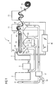
- FIG. 1 shows a schematic representation of a complex papermaking plant 1, as used in today's paper mills. Their construction and the combination of different aggregates are determined by the type of paper, cardboard and paperboard types to be produced as well as the raw materials used.
- the papermaking plant 1 has a spatial extent of about 10 m in width and about 120 m in length.
- the papermaking plant produces up to 1400 m of paper per minute 27. It only takes a few seconds from the first impingement of the suspension or the pulp 39 on the screening device 9 to the finished paper 27, which is finally rolled up in a reel 15. Diluted with water at a ratio of 1: 100, the fibers 30 (see FIG. 2 ) applied together with excipients on the sieve 9 with the sieve 10.
- the fibers are deposited on the screen 10 side by side and on each other.
- the white water 23 can drain or be sucked off by means of several suction chamber regions 24.
- a uniform fiber composite which is further dehydrated by mechanical pressure in a press device 11 and with the aid of steam heat.
- the entire papermaking process is essentially subdivided into the areas of stock preparation, paper machine, finishing and equipment.
- Waste paper and, as a rule, also pulp reach the paper mill in dry form, while wood pulp is normally produced in the same factory and pumped into the material center 3 as a fiber / water mixture, ie a suspension of unvarnished pulp.
- Waste paper and pulp 30 (see FIG. 2 ) are also added with the addition of water in a fiber trough 35 (FIG. FIG. 2 ) dissolved.
- Non-paper components are discharged via various sorting aggregates (not shown here). In the fabric center 3, depending on the desired type of paper, the mixture of different raw materials. Fillers and auxiliaries are also added here to improve paper quality and increase productivity.
- the headbox 7 of the papermaking plant 1 distributes the pulp suspension uniformly over the entire wire width.
- the paper web 27 still contains about 80% water.
- Another dewatering process is carried out by mechanical pressure in the press device 11.
- the paper web 27 is guided by means of an absorbent endless felt cloth between rolls of steel, granite or hard rubber and thereby dehydrated.
- the white water 23 taken up by the suction chamber region 24 is fed to a sorter 5 in part and returned to another part to a fabric scavenger 17.
- the press device 11 is followed by a drying system 13.
- the remaining residual water is evaporated in the drying plant 13.
- Slalom-like, the paper web 27 passes through several steam-heated drying cylinders. In the end, the paper 27 has a residual moisture of a few percent.
- the water vapor formed in the drying plant 13 is sucked off and passed into a heat recovery system, not shown.
- a first electrode 43 is arranged below the sieve device 9 and a second electrode 44 is arranged above the sieve device 9 between the headbox 7 and the starting region of the sieve device 9.
- the electrodes 43 and 44 are arranged such that the surface-distributed fiber suspension 39 extends between them. So that a large-area plasma under atmospheric pressure in the immediate vicinity of the fiber suspension 39 can be produced for the treatment of the fiber suspension 39, the electrodes 43 and 44 are connected to a high-voltage pulse generator 46. With the aid of this high-voltage pulse generator 46, a large-volume plasma with a large cross section and with high power density is produced between the electrodes 43 and 44.
- a plasma density is homogeneously distributed over the treatment area which is covered by the electrodes 43 and 44.
- this large-volume plasma with high power density is produced by superimposing intensive, short-lasting high-voltage pulses having a high pulse repetition rate of 1 kHz on a DC corona discharge.
- a very homogeneous, large-volume plasma with a high power density produced without the plasma constrictions known in DC corona discharges.
- oxygen with argon as carrier gas is optionally introduced into the treatment space between the electrodes 43 and 44 via a gas distributor 81.
- Hydroxyl radicals are particularly advantageously produced with the aid of the oxygen-argon mixture. Hydroxyl radicals are particularly aggressive and oxidizing, thereby a bleaching effect is achieved at the only a few seconds in the treatment area between the electrodes 43 and 44 lingering fiber suspension.
- an electrode system 47, 48 in the press device 11 generates a large-area plasma for the treatment of the paper web 27.
- the first electrode 47 in the press apparatus 11 is designed as a semicircular grid electrode. Due to the semicircular configuration of the electrode 47, it can follow the course of the paper web over a transport roller 12.
- the second electrode 48 in the press device 11 is configured as a plate electrode and arranged such that the transport roller 12 can be guided between the electrodes 47 and 48.
- the plasma treatment area is optionally also supplied via the gas distributor 81 with the gas line 80 with an oxygen-argon mixture here.
- the pressing process compacts the paper structure, a strength increases and a surface quality is decisively influenced.
- the molecular structure of the paper surface is further altered.
- the strength of the paper 27 is increased and printability improved.
- a streamer is a special form of a linearly moving plasma cloud or a developing discharge channel that forms due to the excited high external field strength. An assembly of such streamer takes place within less than 10 ns and merges very quickly into a thermal breakdown channel.
- the aforementioned arrangements of the electrode systems, with the paper web 27 between the electrodes used for streamer discharge, is particularly advantageous, as the paper 27 thereby partially acts as a dielectric barrier, thereby suppressing the transition from the streamer puncture.
- FIG. 2 shows a bleaching device 38 according to the invention with a second embodiment.
- a raw material 30, in particular pulp is conveyed via a conveyor belt 33 into a fiber trough 35.
- the raw material 30 is mixed with water and pumped via a pipeline 36 into a bleaching trough 37.
- a first electrode 43 'and a second electrode 44' are each designed as a circular-area grid electrode.
- the first electrode 43 ' is arranged in the gas space of the pulp fiber suspension 39 filled in the bleaching trough 37.
- the second electrode 44 ' is arranged inside the bleaching trough 37 and is thus completely covered by the pulp fiber suspension 39.
- a large-area cold plasma is generated by means of the high-voltage pulse generator 46.
- the radical OH in the suspension 39 is preferably, O, O 3 produced. These radicals trigger a bleaching chemical reaction.
- the high voltage pulse generator 46 is operated to generate high voltage pulses of 1 ⁇ s duration between the electrodes 43 'and 44'.
- One for the generation of radicals and ozone in the pulp fiber suspension necessary DC voltage is approximately at some 10 kV to 100 kV.
- the high voltage pulses are superimposed on the DC voltage to form a total amplitude of a few 10 kV to over 100 kV.
- the radicals are generated in situ. Thus, large total amounts of radicals can be introduced into the suspension 39.
- the radicals are also very finely distributed in the suspension generated, so that the previous effort required to mix chemicals with the suspension can be reduced.
- an oxygen-argon mixture which has been treated in a gas distributor 81, is introduced into the bleaching trough 37 via a gas line 80.
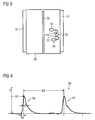
- FIG. 3 shows as a third embodiment, a sectional view of a bleaching vessel.
- a high voltage electrode 50 is arranged in the middle of the bleaching vessel.
- the outer jacket of the bleaching vessel is prepared as a counterelectrode 51.
- a pulp fiber suspension 39 In the bleaching vessel is a pulp fiber suspension 39.
- a streamer 53 is shown between the electrodes 50 and 51. Radicals 59 are generated in streamers by the collision of energetic electrons with water molecules or suspension molecules, thereby dissociating or exciting them. Upon dissociation, radicals 59 are immediately released, while upon excitation by a subsequent radiant transition, UV light is generated. This generated UV light in turn reacts with water molecules and dissociates them.
- Bleaching vessel shown can also be used as a device for the passage of the suspension 39.
- the device is not designed as a bleaching vessel, but as a kind of tubular reactor, ie without a bottom. With this tube reactor, a passage of the suspension can be carried out with simultaneous plasma generation.
- these radicals 59 and oxidants 57 directly attack the high-molecular-weight dyes and destroy them to such an extent that the color effect of the molecules is eliminated.
- Microorganisms which release, for example, carbohydrate-cleaved enzymes such as the enzyme cellulase, with which the cellulose in the suspension 39 is decomposed as a fiber base and serves as a decomposed, short-chain carbohydrate for the microorganisms, are also inhibited or completely destroyed.
- the microorganisms are killed, minimizing cellulase production.
- a simultaneous degradation of a catalase can build up in addition to the radicals and a H 2 O 2 concentration. This in turn contributes to the direct cellulase degradation as well as to the sterilization of the microorganisms produced by the cellulase.
- FIG. 4 the voltage curve of the high voltage pulses used is shown.
- the abscissa shows the time in ms and the ordinate the voltage in kV.
- the units are chosen arbitrarily.
- a level of about 100 kV DC voltage coincides with the abscissa shown.
- the illustrated pulse voltage is thus superimposed on the DC voltage.
- the result is a total amplitude of about 500 kV.
- the pulses 66 and 67 have a pulse width 62 of less than 1 ⁇ s, wherein the individual pulses 66, 67 have a high rising edge with a rise time 64 and a less steeply sloping edge.
- the pulse repetition time 63 is typically between 10 ⁇ s and 100 ms.
- the individual pulses 66, 67 have such a total amplitude that a predefined energy density is achieved beyond the predetermined direct voltage.
- the pulse rise time 64 is usually short compared to the pulse drop time.
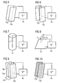
- FIG. 5 to FIG. 10 show further examples of electrode systems for generating corona discharges in preferably aqueous media, in particular for alternative use in the aforementioned embodiments.
- a plate-and-plate arrangement of a first plate 70a as an electrode and a second plate 70b as an electrode is illustrated.
- the first plate 70a and the second plate 70b are arranged parallel to each other.
- the first plate 70a forms the high voltage electrode and is connected to the high voltage pulse generator 46 via a high voltage cable.
- the second plate 70b forms the counter electrode and is connected as a grounded electrode to the high voltage pulse generator 46 in connection.
- FIG. 6 A corresponding arrangement with specially flat plate electrodes is in FIG. 6 shown. Again there are two solid plate electrodes 70a and 70c at a fixed distance with a high voltage electrode 71 in the middle. In this plate-wire plate assembly, the high voltage electrode 71 executed as a solid wire and connected to the high voltage output of the high voltage pulse generator 46. The grounded plates 70a, 70c are also in communication with the high voltage pulse generator.
- FIG. 7 shows a wire-tube arrangement as an electrode system.
- a high-voltage electrode 71 projects centrally into a cylindrical electrode 72.
- the high voltage electrode 71 is made as a solid wire and connected to the high voltage pulse generator 46.
- the cylindrical electrode 72 which is preferably configured as a wire mesh, is grounded and communicates with the high voltage pulse generator 46.
- FIG. 8 shows a tip-plate assembly as an electrode system.
- the example three tips 73 are connected via a high voltage line to the high voltage pulse generator 46.
- the tips 73 are arranged at right angles to a grounded plate electrode 74.
- the distance of the tip electrodes 73 to the plate electrode 74 is adjustable and thus can be adapted for different process conditions.
- FIG. 9 shows an electrode system assembly comprising 3 plates 70a, 70d and 70e.
- the first plate 70a which is connected as a high-voltage electrode to the high-voltage pulse generator 46, is arranged centrally between two solid plates 70d and 70e.
- the plates 70a and 70b are connected via a plate connector 70f. Since the plate 70d as a grounded counter electrode is in communication with the high voltage pulse generator 46, the plate 70e above the plate connector 70f also functions as a grounded counter electrode.
- FIG. 10 shows an electrode system as a grid-grid arrangement. Analogous to FIG. 5 Here, a first grid 75a and a second grid 75b are parallel to each other.
- the first grid 75a forms the high voltage electrode and is with the high voltage pulse generator 46 connected.
- the second grid 75b forms the grounded counter electrode and communicates with the high voltage pulse generator 46.
- FIG. 11 A hybrid discharge in which an electrode 75a is entirely outside a pulp 39 to be bleached and a second electrode 76b is wholly or partially immersed in the pulp 39 is shown in FIG. 11 generated.
- the electrode 76a is designed as a grid electrode and is connected to the high-voltage pulse generator 46.
- the grounded counter-electrode 76b is also designed as a grid electrode.
- a first charge cloud 68a is formed.
- the chemically active substances can enter the suspension 39 and eliminate unwanted impurities in addition to the bleaching effect.
- charge clouds 68b, 68c are preferably formed at locations with locally increased field strength.
- the charge clouds 68a, 68b, 68c release in the suspension 39 radicals, such as O, OH, HOO, but above all strong oxidants such as ozone and / or H 2 O 2 .
- these chemically active substances destroy microorganisms such as bacteria and yeasts with high efficiency.
- FIG. 12 is shown as another embodiment, a bleaching tub with a vessel wall 77 in a plan view.
- a plate or grid arrangement with curved surfaces for adaptation to the vessel walls or use of the vessel walls is used as the electrode.
- a multiple wire electrode 79 is considered a concentric electrode, arranged following the course of the vessel wall 77 and communicates with the high voltage pulse generator 46 in connection. It faces two counterelectrodes: on the one hand the vessel wall 77 and on the other hand a plate electrode 78.
- the high voltage electrode 79 is arranged without contact between the vessel wall 77 and the plate electrode 78.
- the vessel wall 77 and the plate electrode 78 are electrically conductively connected to each other and thus form the grounded counterelectrodes which are in communication with the high voltage pulse generator 46.
- a high-voltage electrode 50 comprises a plurality of electrically connected rod electrodes and is arranged in the near-surface gas space of the pulp 39 such that their rods are parallel to the surface.
- a grounded counter electrode 51 is designed as a solid plate and arranged in distributed over the entire surface equidistant distances to the high voltage electrode 50.
- 39 charge clouds develop at the boundary layer between air and suspension, as indicated for example by the charge clouds 68d and 68e.
- the charge clouds also ensure penetration of the chemically active substances into the suspension 39.
- the suspension 39 is guided in this case in an upwardly open suspension channel 37a.
- the wall of the suspension channel 37a is additionally connected to the counterelectrode 51.
- FIG. 14 shows in a last embodiment, a pulsed corona discharge system in an aqueous solution or pulp 39.
- the electrode system is analogous to FIG. 3 formed as a coaxial wire tube electrode system.
- the high voltage electrode 50 is arranged coaxially with the counter electrode 51 forming the vessel wall.
- finest gas bubbles are introduced into the discharge area via a gas line 80 by means of a gas distributor 81 initiated.
- gas bubbles 82 and 83 are preferably formed to FIG. 3 explained streamers. Owing to the streamer discharges, oxidants 57 are formed. Thus, certain radicals are generated in the suspension.
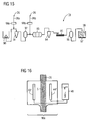
- FIG. 15 shows a schematic representation of a stock preparation plant 1a.
- a dissolver 90 fibrous materials are suspended in an aqueous binder at the beginning of the stock preparation process.
- the dissolution device 90 is connected to a chemical addition device 91 via a piping system. Further, the piping between the dissolver 90 and the chemical addition device 91 is connected to a first dilution water inlet 26a.
- the chemical addition device 91 is connected to a first purification stage 92 via a pipe system.
- the first cleaning stage 92 is further connected to a flotation stage 93 via a pipe system. Between the first purification stage 92 and the flotation stage 93, a second dilution water inlet 26b is arranged.
- a second purification stage 94 connects to the flotation stage 93 via a piping system. From the second purification stage 94, the suspension or pulp also passes through a piping system in a thickening device 95.
- the thickening device 95 is connected via a piping system with a bleaching container 96 in connection. From the bleaching container 96, the suspension or pulp 39 is pumped into a chest 97. From the bin 97, the treated fibrous materials or pulp 39 are available for further processing.
- the chemical addition device 5 may add various chemical adjuncts, i.a. Bleaching agents supplementing a plasma bleaching effect.
- dilution water 26 is added at locations 26a and 26b.
- material resolution of fibrous materials in the dissolution apparatus 3 is preferably carried out with a consistency of up to 17%.
- the suspension of fibrous materials for the subsequent chemical addition device 91 and the first purification stage 92 with the dilution water 26 at the dilution water inlet 26a is diluted to about 5.8 to 6%.
- the dilution water 26 is treated at the first dilution water inlet 19a by means of a first plasma reactor 23a with a cold plasma or a gas discharge.
- a first plasma reactor 23a By treating the dilution water 26 before the actual dilution point at which the dilution water 26 is mixed with the suspension in the pipeline system, certain radicals are generated in the dilution water 26 (OH - , HOO - , O, O 3 ). These radicals, which pass through the dilution water 26 into the stock suspension, trigger bleaching chemical reactions in the stock suspension at the beginning of the stock preparation process. Also, they can mask or eliminate sticky contaminants of the pulps. These bleaching chemical reactions or radicals act directly on the fibrous materials and thus provide the desired bleaching result.
- the stock suspension is diluted to approximately 1 to 1.3% by a second dilution water feed 26b. Also at the point 26b, the dilution water 26 is treated via a second plasma reactor 23b before being mixed with the suspension with a cold plasma or a gas discharge.
- the plasma reactors 98a and 98b are preferably arranged directly in the vicinity of the respective feed points of the dilution water 26, in particular at a distance such that the remaining pipe length to the feed point is preferably a few meters, preferably about 50 cm, in particular only a few cm.
- the stock suspension 39 After passing through the second cleaning stage 94, the stock suspension 39 is thickened with a consistency of about 1% in a thickening device 13.
- a further treatment with a kneading disperger, for the reduction of, for example, residual color particles, can optionally be used at this point.
- FIG. 16 shows one of the two in a first embodiment example FIG. 15 known plasma reactors 98a and 98b in a sectional view.
- the plasma reactor 23 a is prepared in such a way that an unhindered flow through the dilution water 26 is made possible.
- the dilution water 26 falls or flows - preferably as a free water jet in the flow direction S - through a gap, which is given by two spaced-apart electrodes 43 "and 44".
- the first electrode 43 " is connected via a high-voltage line to a high-voltage pulse generator 46.
- a corona discharge or a gas discharge between the two electrodes 43" and 44 ", the second electrode 44 is also connected to the high-voltage pulse generator 46 via a high-voltage line
Landscapes
- Engineering & Computer Science (AREA)
- Life Sciences & Earth Sciences (AREA)
- Wood Science & Technology (AREA)
- Mechanical Engineering (AREA)
- Paper (AREA)
Claims (66)
- Dispositif (38) de blanchiment de matières fibreuses non entrelacées en suspension, notamment sous la forme de pâte ou de bouillie de fibres, dans/ou sur un volume de traitement donné par des parois de démarcation, dans lequel le volume de traitement peut être rempli par la suspension ou elle peut y passer,
caractérisé par au moins une première électrode (43') et un générateur (46) d'impulsions en haute tension, qui est relié à la première électrode (43') et par lequel un plasma peut être produit dans le volume de traitement et/ou dans son environnement immédiat. - Dispositif (38) de blanchiment suivant la revendication 1,
caractérisé en ce que le plasma est produit à une distance plus petite que 20 cm, de préférence plus petite que 10 cm, de préférence plus petite que 5 cm du volume de traitement. - Dispositif (38) de blanchiment suivant la revendication 1 ou 2,
caractérisé en ce que les substances fibreuses sont propres à la fabrication du papier, du carton épais ou du carton et/ou peuvent être apportées en tant que produits à traiter à une opération de fabrication de ce genre. - Dispositif (38) de blanchiment suivant l'une des revendications 1 à 3,
caractérisé en ce que le volume de traitement est propre à être rempli ou à être traversé par la suspension, de préférence par une matière (30) première dans la fabrication du papier, du carton épais ou du carton, notamment par une pâte (9) à blanchir ou par une bouillie de fibres à blanchir. - Dispositif (38) de blanchiment suivant l'une des revendications 1 à 4,
caractérisé en ce qu'il y a au moins une deuxième électrode (44') pour la production de plasma. - Dispositif (38) de blanchiment suivant l'une des revendications 1 à 5,
caractérisé en ce qu'au moins l'une des électrodes (44') est disposée de manière à venir en contact avec la suspension lorsqu'elle remplit le volume de traitement ou lorsqu'elle y passe. - Dispositif (38) de blanchiment suivant l'une des revendications 1 à 6,
caractérisé en ce qu'au moins l'une des électrodes (43', 44') est disposée de manière à produire le plasma, de préférence pour la plus grande partie, dans un volume près de la surface, sous ou sur la surface de la suspension remplissant le volume. - Dispositif (38) de blanchiment suivant l'une des revendications 5 à 7,
caractérisé en ce que les électrodes (43', 44') sont à deux dimensions, la deuxième électrode (44') pouvant être immergée, au moins en partie dans la suspension et/ou la première électrode (43') étant disposée parallèlement à la deuxième électrode (44') en dehors de la suspension. - Dispositif (38) de blanchiment suivant l'une des revendications 5 à 8,
caractérisé en ce que les électrodes (43', 44') sont à deux dimensions, la première électrode (43') et la deuxième électrode (44') étant disposées parallèlement l'une à l'autre dans la zone proche de la surface de la suspension. - Dispositif (38) de blanchiment suivant l'une des revendications 1 à 9,
caractérisé en ce qu'une paroi (51) de démarcation du volume de traitement sert d'électrode. - Dispositif (38) de blanchiment suivant l'une des revendications 1 à 10,
caractérisé en ce que le volume de traitement est constitué sous la forme d'une canalisation (36, 72, 77), notamment sous la forme d'un élément de liaison, pour le transport de la suspension. - Dispositif de blanchiment suivant l'une des revendications 1 à 11,
caractérisé en ce qu'au moins une électrode est constituée sous la forme d'une plaque (70a, 70b). - Dispositif (38) suivant la revendication 12,
caractérisé en ce que les électrodes sont disposées sous la forme d'au moins deux plaques (70a, 70b) opposées l'une à l'autre, en étant de préférence parallèles entre elles. - Dispositif de blanchiment suivant l'une des revendications 1 à 13,
caractérisé en ce qu'au moins une électrode est sous la forme d'un filtre (71). - Dispositif de blanchiment suivant l'une des revendications 1 à 14,
caractérisé en ce qu'au moins une électrode est sous la forme d'un treillis de fil métallique, notamment d'un réseau (75a, 75b) de fils métalliques. - Dispositif (38) de blanchiment suivant l'une des revendications 1 à 15,
caractérisé en ce qu'au moins une électrode est sous la forme d'un réseau (75a, 75b), notamment sous la forme d'un agencement de barres de section droite circulaire et/ou de réglettes plates, s'entrecroisant à angle droit ou de manière inclinée, de préférence sous la forme d'un tamis. - Dispositif (38) de blanchiment suivant l'une des revendications 14 à 16,
caractérisé en ce que les électrodes sont disposées sous la forme d'au moins deux réseaux (75a, 75b) opposés, s'étendant de préférence parallèlement entre eux. - Dispositif (38) de blanchiment suivant l'une des revendications 1 à 15,
caractérisé en ce qu'au moins une électrode a une pointe (73) ou plusieurs pointes (73). - Dispositif (38) de blanchiment suivant l'une des revendications 1 à 16,
caractérisé en ce qu'au moins une électrode est sous la forme d'un tube (36, 72, 77). - Dispositif (38) de blanchiment suivant la revendication 19,
caractérisé en ce que l'électrode est sous la forme d'un tube (72), à l'intérieur duquel est disposé, de préférence coaxialement, un fil (71) métallique. - Dispositif de blanchiment suivant l'une des revendications 5 à 20,
caractérisé en ce que les électrodes sont disposées de manière à avoir, entre deux plaques (70d, 70e) reliées électriquement entre elles par au moins une liaison (70f) de plaque et formant la première électrode, un fil (71) métallique pour un réseau (75a) comme deuxième électrode. - Dispositif (38) de blanchiment suivant l'une des revendications 1 à 21,
caractérisé en ce que la au moins une électrode (78, 79), constituée de préférence en deux dimensions, est disposée au moins en partie parallèlement à une surface latérale, notamment courbée, ou à une paroi (77) de démarcation du volume de traitement. - Dispositif (38) de blanchiment suivant l'une des revendications 1 à 22,
caractérisé par un moyen (81) d'injection de gaz, notamment d'air ou d'oxygène, de préférence d'oxygène pur ou d'oxygène ayant par exemple un gaz rare comme gaz porteur, dans le volume de traitement. - Procédé de traitement de matières fibreuses non entrelacées en suspension, notamment sous la forme de pâte ou de bouillie de fibres, de préférence pour faire fonctionner le dispositif de blanchiment suivant l'une des revendications précédentes, caractérisé en ce que l'on met la suspension, ou une eau (26) de dilution qui lui est ajoutée, en contact avec un plasma de grande surface, de préférence non thermique, sous au moins la pression atmosphérique, en ce qu'on produit le plasma à proximité immédiate de la suspension ou de l'eau (26) de dilution ou on produit dans la suspension ou dans l'eau (26) de dilution ou à proximité immédiate de la suspension ou de l'eau (26) de dilution, une décharge dans un gaz, notamment une décharge par effet couronne, sous au moins la pression atmosphérique.
- Procédé suivant la revendication 24,
caractérisé en ce que l'on produit le plasma à une distance plus petite que 20 cm, de préférence plus petite que 10 cm, de préférence plus petite que 5 cm, de la suspension. - Procédé suivant la revendication 24 ou 25,
caractérisé en ce que la suspension est propre à la fabrication du papier et du carton épais ou du carton. - Procédé suivant l'une des revendications 24 à 26,
caractérisé en ce que l'on utilise une feuille humide ou mouillée comme suspension. - Procédé suivant l'une des revendications 24 à 27,
caractérisé en ce que, pour produire le plasma ou la décharge dans un gaz, on produit, entre des électrodes (43, 44), des impulsions (66, 67) à haute tension d'une durée (62) de moins de 10 µs. - Procédé suivant l'une des revendications 24 à 28,
caractérisé en ce que l'on applique à la suspension le plasma ou la décharge dans un gaz avant et/ou pendant la formation de feuille, notamment lors du passage à travers ou sur un dispositif (9) de tamisage. - Procédé suivant l'une des revendications 24 à 29,
caractérisé en ce que l'on met la suspension des deux côtés en contact avec le plasma ou on la traite au moyen de la décharge dans un gaz. - Procédé suivant l'une des revendications 24 à 30,
caractérisé en ce que l'on utilise le plasma ou la décharge dans un gaz pour blanchir la suspension, la pâte (39) ou la bouillie de fibres, notamment dans une lessiveuse, dans un récipient (37) de blanchiment ou dans un conduit. - Procédé suivant l'une des revendications 24 à 31,
caractérisé en ce que l'on met la suspension, la pâte (39) ou la bouillie de fibres, en contact avec au moins une électrode pour la production du plasma ou de la décharge dans un gaz. - Procédé suivant l'une des revendications 24 à 32,
caractérisé en ce que l'on produit le plasma ou la suspension dans un gaz dans la suspension. - Procédé suivant l'une des revendications 24 à 33,
caractérisé en ce que la teneur en liquide porteur, notamment en eau, de la suspension est comprise entre 40% et 99,9%, de préférence entre 80% et 98% et notamment entre 85% et 98%. - Procédé suivant l'une des revendications 28 à 34,
caractérisé en ce que l'on produit dans le plasma ou au moyen de la décharge dans un gaz des radicaux (59) qui agissent sur les matières fibreuses. - Procédé suivant la revendication 35,
caractérisé en ce que, pour des états différents de suspensions dans une opération de fabrication du papier, du carton épais ou du carton, notamment à des stades opératoires différents, on utilise des radicaux (59) de nature différente ou de composition différente. - Procédé suivant la revendication 35 ou 36,
caractérisé en ce que l'on soumet la suspension, dans un stade opératoire d'une opération de fabrication du papier ou du carton épais, à des radicaux (59) de nature ou de composition différents, de préférence successivement dans le temps. - Procédé suivant l'une des revendications 35 à 37,
caractérisé en ce que l'on produit comme radicaux (59) de l'ozone (O3), du peroxyde d'hydrogène (H2O2), des radicaux hydroxyle (OH), HO2 et/ou HO2. - Procédé suivant l'une des revendications 35 à 38,
caractérisé en ce que, lors du blanchiment, on applique dans la suspension ou dans la pâte (39) ou dans la bouillie de fibres le plasma ou la décharge dans un gaz, de manière à former de l'ozone (O3) et/ou du peroxyde d'hydrogène (H2O2) se multipliant sous la forme de radicaux (59). - Procédé suivant l'une des revendications 35 à 39,
caractérisé en ce que, lors du tamisage et/ou dans la suspension ou la pâte (39) ou la bouillie de fibres, répartie à plat, ou dans la feuille en formation ou formée mais pas encore pressée, on applique le plasma ou la décharge dans un gaz, de manière à former de l'hydroxyde (OH), HO2 et/ou HO2 se multipliant sous la forme de radicaux (59). - Procédé suivant l'une des revendications 35 à 40,
caractérisé en ce que l'on se rend maître d'une vitesse de production des radicaux (59) et/ou de la composition des radicaux (59) produits en influant sur une amplitude (U), une durée (62) des impulsions et/ou un taux (63) de répétition des impulsions (66, 67) de haute tension. - Procédé suivant la revendication 41,
caractérisé en ce que pour se rendre maître et pour réguler le taux de production et/ou la nature des radicaux (59) produits, on mesure une concentration des radicaux (59) produits. - Procédé suivant la revendication 41 ou 42,
caractérisé en ce que pour se rendre maître et pour réguler le taux de production ou la composition des radicaux (59) produits, on mesure une propriété de la suspension, de préférence une propriété qualitative, notamment son opacité, sa brillance, sa blancheur, sa fluorescence ou son point de couleur. - Procédé suivant l'une des revendications 42 ou 43,
caractérisé en ce que l'on mesure la concentration ou la propriété « online ». - Procédé suivant l'une des revendications 41 à 44,
caractérisé en ce que, pour la régulation, on modifie l'amplitude (U) des impulsions (66, 67) à haute tension à taux (63) de répétition constant. - Procédé suivant l'une des revendications 41 à 45,
caractérisé en ce que, pour la régulation, on modifie le taux (63) de répétition des impulsions (66, 67) à haute tension à amplitude (U) constante. - Procédé suivant l'une des revendications 24 à 46,
caractérisé en ce que l'on enrichit en oxygène la suspension ou la pâte (39) ou la bouillie de fibres, de préférence pour le blanchiment, dans la zone soumise au plasma. - Procédé suivant l'une des revendications 24 à 47,
caractérisé en ce que l'on utilise une durée (62) d'impulsion à haute tension de moins de 100 ns dans la suspension ou dans la pâte (39) ou dans la bouillie de fibres, de préférence pour le blanchiment. - Procédé suivant l'une des revendications 24 à 48,
caractérisé en ce que la suspension, la pâte (39) ou la bouillie de fibres ou une feuille se formant ou déjà formée mais pas encore pressée, répartie à plat, est entourée, notamment lors du tamisage, dans la zone soumise au plasma, d'une atmosphère enrichie en vapeur d'eau. - Procédé suivant l'une des revendications 41 à 49,
caractérisé en ce que l'on utilise une durée (62) d'impulsion en haute tension de 100 ns à 1 µs, sur la suspension, la pâte (39) ou la bouillie de fibres ou une feuille se formant ou déjà formée mais pas encore pressée, répartie à plat, notamment lors du tamisage. - Procédé suivant l'une des revendications 41 à 50,
caractérisé en ce que, pour une suspension, une pâte (39) ou une bouillie de fibres ou une feuille se formant ou déjà formée mais pas encore pressée, répartie à plat, on applique aux électrodes, lors du tamisage, une amplitude (U) en haute tension, correspondant au moins à deux fois, de préférence au moins à trois fois, une tension d'amorçage à effet couronne. - Procédé suivant l'une des revendications 41 à 51,
caractérisé en ce que, pour la production du plasma ou de la décharge à effet couronne, on produit une décharge à effet couronne en tension continue et on superpose les impulsions (66, 67) à haute tension à la décharge à effet couronne en tension continue. - Procédé suivant l'une des revendications 41 à 52,
caractérisé en ce que l'on utilise un taux (63) de répétition des impulsions compris entre 10Hz et 5kHz, notamment allant de 10Hz à 10kHz. - Procédé suivant l'une des revendications 41 à 53,
caractérisé en ce que l'on règle l'énergie électrique d'injection de puissance dans le plasma, d'une manière prépondérante, par la régulation de l'amplitude (U), de la durée (62) d'impulsion et du taux (63) de répétition des impulsions à haute tension superposées. - Procédé suivant l'une des revendications 28 à 54,
caractérisé en ce que l'on applique des impulsions (66, 67) à haute tension d'une durée (62) de moins de 3 µs, de préférence de moins de 1 µs, de préférence de moins de 500 ns. - Procédé suivant l'une des revendications 28 à 55,
caractérisé en ce que l'on produit un plasma homogène de grand volume et ayant une grande densité de puissance, sans qu'il se produise des strictions de plasma ou des claquages. - Procédé suivant l'une des revendications 28 à 56,
caractérisé en ce que l'on utilise une tension en courant continu d'une amplitude telle, qu'il se forme dans le plasma une décharge à effet couronne en courant continu stable seulement en liaison avec la superposition d'impulsions à haute tension. - Procédé suivant la revendication 57,
caractérisé en ce que la tension en courant continu appliquée est inférieure à la tension pour un fonctionnement stable sans superposition d'impulsions à haute tension. - Procédé suivant la revendication 57 ou 58,
caractérisé en ce que l'amplitude totale utilisée (tension en courant continu + amplitude des impulsions) est supérieure à la tension de claquage statique de l'agencement d'électrodes. - Procédé suivant l'une des revendications 57 à 59,
caractérisé en ce que l'amplitude totale utilisée correspond de deux à cinq fois la tension de claquage statique de l'agencement d'électrodes. - Procédé suivant l'une des revendications 57 à 60,
caractérisé en ce que l'amplitude (U) des impulsions de haute tension est comprise entre 10% et 1000% de la tension en courant continu appliquée. - Procédé suivant l'une des revendications 28 à 61,
caractérisé en ce que l'on produit un courant de gaz perpendiculairement à l'agencement (43, 44) d'électrodes. - Procédé suivant l'une des revendications 28 à 62,
caractérisé en ce que l'on produit un courant de gaz parallèlement à l'agencement (43, 44) d'électrodes. - Procédé suivant l'une des revendications 24 à 63,
caractérisé en ce que l'on réduit, dans la suspension, des impuretés formées par des colorants organiques, des substances biocatalytiques et/ou des micro-organismes et/ou d'autres substances biologiques. - Procédé suivant l'une des revendications 24 à 64,
caractérisé en ce que l'on réduit des impuretés collantes. - Procédé suivant la revendication 24,
caractérisé en ce que l'on traite l'eau (26) de dilution en outre par le plasma ou par la décharge dans un gaz, avant d'ajouter l'eau (26) de dilution à la suspension.
Applications Claiming Priority (3)
| Application Number | Priority Date | Filing Date | Title |
|---|---|---|---|
| DE102005028046 | 2005-06-16 | ||
| DE102005049230A DE102005049230A1 (de) | 2005-06-16 | 2005-10-14 | Verfahren zur Behandlung unverwobener Faserstoffe und Vorrichtung zum Bleichen |
| PCT/EP2006/063209 WO2006134127A1 (fr) | 2005-06-16 | 2006-06-14 | Procede pour traiter des matieres fibreuses non entrelacees et dispositif de blanchiment |
Publications (2)
| Publication Number | Publication Date |
|---|---|
| EP1891266A1 EP1891266A1 (fr) | 2008-02-27 |
| EP1891266B1 true EP1891266B1 (fr) | 2014-07-30 |
Family
ID=37014068
Family Applications (1)
| Application Number | Title | Priority Date | Filing Date |
|---|---|---|---|
| EP06763710.8A Not-in-force EP1891266B1 (fr) | 2005-06-16 | 2006-06-14 | Procede pour traiter des matieres fibreuses non entrelacees et dispositif de blanchiment |
Country Status (4)
| Country | Link |
|---|---|
| EP (1) | EP1891266B1 (fr) |
| DE (1) | DE102005049230A1 (fr) |
| ES (1) | ES2520891T3 (fr) |
| WO (1) | WO2006134127A1 (fr) |
Families Citing this family (5)
| Publication number | Priority date | Publication date | Assignee | Title |
|---|---|---|---|---|
| DE102006024404A1 (de) * | 2006-05-24 | 2007-11-29 | Siemens Ag | Verfahren zur Verbesserung der Qualität einer Faser-Suspension |
| DE102006024405A1 (de) * | 2006-05-24 | 2007-11-29 | Siemens Ag | Verfahren zur Reduzierung klebender Verunreinigungen bei der Papierherstellung |
| US9382633B2 (en) * | 2012-12-21 | 2016-07-05 | Colorado Energy Research Technologies, LLC | Systems and methods of improved fermentation |
| CN106042113A (zh) * | 2016-08-05 | 2016-10-26 | 沭阳县旺强木制品有限公司 | 一种木粉漂白机装置 |
| CN107941897B (zh) * | 2017-11-30 | 2024-01-02 | 北京市北分仪器技术有限责任公司 | 一种双极性可控脉冲电晕放电电离源及其离子迁移谱仪 |
Family Cites Families (5)
| Publication number | Priority date | Publication date | Assignee | Title |
|---|---|---|---|---|
| CA973660A (en) * | 1972-05-29 | 1975-09-02 | Thomas Joachimides | Treatment of cellulosic matter with active nitrogen |
| CZ281826B6 (cs) * | 1993-10-27 | 1997-02-12 | Masarykova Univerzita V Brně Katedra Fyzikální Elektroniky Přírod. Fakulty | Způsob bělení a zvyšování adheze vlákenných materiálů k barvivům |
| JPH11247098A (ja) * | 1998-03-03 | 1999-09-14 | Toppan Printing Co Ltd | 紫外線カット紙およびその製造方法 |
| DE19836669A1 (de) * | 1998-08-13 | 2000-02-24 | Kuesters Eduard Maschf | Verfahren zur Oberflächen-Vorbehandlung von Papier oder Karton |
| EP1623072A1 (fr) * | 2003-05-13 | 2006-02-08 | Università Degli Studi Di Milano - Bicocca | Procede de traitement au plasma du papier et du carton |
-
2005
- 2005-10-14 DE DE102005049230A patent/DE102005049230A1/de not_active Ceased
-
2006
- 2006-06-14 EP EP06763710.8A patent/EP1891266B1/fr not_active Not-in-force
- 2006-06-14 WO PCT/EP2006/063209 patent/WO2006134127A1/fr not_active Ceased
- 2006-06-14 ES ES06763710.8T patent/ES2520891T3/es active Active
Also Published As
| Publication number | Publication date |
|---|---|
| DE102005049230A1 (de) | 2006-12-28 |
| WO2006134127A1 (fr) | 2006-12-21 |
| EP1891266A1 (fr) | 2008-02-27 |
| ES2520891T3 (es) | 2014-11-12 |
Similar Documents
| Publication | Publication Date | Title |
|---|---|---|
| EP2029491A1 (fr) | Procédé pour réduire les impuretés dans un système d'eau lors de la fabrication de feuilles | |
| DE102010001801A1 (de) | Abwasserreinigungsanlage | |
| EP1891266B1 (fr) | Procede pour traiter des matieres fibreuses non entrelacees et dispositif de blanchiment | |
| DE102010001808A1 (de) | Abwasserreinigungsanlage | |
| EP2035621B1 (fr) | Procédé de réduction des impuretés collantes dans la fabrication du papier | |
| WO2012004196A1 (fr) | Ions métalliques | |
| EP1896654B1 (fr) | Dispositif de tamisage pour la fabrication du papier, et procede de traitement de matiere fibreuse a fibres non entrecroisees | |
| EP1893803B9 (fr) | Procede de traitement d'un produit se presentant lors de la fabrication du papier, carton-pate ou carton | |
| EP2021541B1 (fr) | Procédé pour améliorer la qualité d'une suspension de fibres | |
| EP1891265B1 (fr) | Procede pour traiter un produit au moyen d'un plasma a grande surface | |
| DE102005049287A1 (de) | Siebvorrichtung für die Herstellung von Papier und Verfahren zur Behandlung unverwobener Faserstoffe | |
| EP1891267B1 (fr) | Dispositif de pressage destine a comprimer le papier et/ou a eliminer le liquide entraine du papier, et procede correspondant | |
| EP1893809B1 (fr) | Procede et dispositif permettant d'ameliorer la qualite du papier | |
| DE2660362C3 (de) | Verfahren und Vorrichtung zur kontinuierlichen Behandlung von Faserstoffbrei mit einem gasförmigen Medium | |
| DE1203592B (de) | Verfahren zum Bleichen von cellulosehaltigen Faserstoffen | |
| EP2886713B1 (fr) | Procédé de traitement de fibres de papier et dispositif de traitement de fibres de papier | |
| DE19704183A1 (de) | Verfahren und Vorrichtung zur reduzierenden Bleiche von hochkonsistentem Papierfaserstoff | |
| WO2009015700A1 (fr) | Utilisation de presses de lavage et à vis pour le lavage d'une matière première et d'une matière fibreuse |
Legal Events
| Date | Code | Title | Description |
|---|---|---|---|
| PUAI | Public reference made under article 153(3) epc to a published international application that has entered the european phase |
Free format text: ORIGINAL CODE: 0009012 |
|
| 17P | Request for examination filed |
Effective date: 20071214 |
|
| AK | Designated contracting states |
Kind code of ref document: A1 Designated state(s): AT BE BG CH CY CZ DE DK EE ES FI FR GB GR HU IE IS IT LI LT LU LV MC NL PL PT RO SE SI SK TR |
|
| DAX | Request for extension of the european patent (deleted) | ||
| DAX | Request for extension of the european patent (deleted) | ||
| RAP1 | Party data changed (applicant data changed or rights of an application transferred) |
Owner name: SIEMENS AKTIENGESELLSCHAFT |
|
| GRAP | Despatch of communication of intention to grant a patent |
Free format text: ORIGINAL CODE: EPIDOSNIGR1 |
|
| INTG | Intention to grant announced |
Effective date: 20140214 |
|
| GRAS | Grant fee paid |
Free format text: ORIGINAL CODE: EPIDOSNIGR3 |
|
| GRAA | (expected) grant |
Free format text: ORIGINAL CODE: 0009210 |
|
| AK | Designated contracting states |
Kind code of ref document: B1 Designated state(s): AT BE BG CH CY CZ DE DK EE ES FI FR GB GR HU IE IS IT LI LT LU LV MC NL PL PT RO SE SI SK TR |
|
| REG | Reference to a national code |
Ref country code: GB Ref legal event code: FG4D Free format text: NOT ENGLISH |
|
| REG | Reference to a national code |
Ref country code: CH Ref legal event code: EP |
|
| REG | Reference to a national code |
Ref country code: AT Ref legal event code: REF Ref document number: 680064 Country of ref document: AT Kind code of ref document: T Effective date: 20140815 |
|
| REG | Reference to a national code |
Ref country code: IE Ref legal event code: FG4D Free format text: LANGUAGE OF EP DOCUMENT: GERMAN |
|
| REG | Reference to a national code |
Ref country code: DE Ref legal event code: R096 Ref document number: 502006013886 Country of ref document: DE Effective date: 20140904 |
|
| REG | Reference to a national code |
Ref country code: SE Ref legal event code: TRGR |
|
| REG | Reference to a national code |
Ref country code: ES Ref legal event code: FG2A Ref document number: 2520891 Country of ref document: ES Kind code of ref document: T3 Effective date: 20141112 |
|
| REG | Reference to a national code |
Ref country code: NL Ref legal event code: VDEP Effective date: 20140730 |
|
| REG | Reference to a national code |
Ref country code: LT Ref legal event code: MG4D |
|
| PG25 | Lapsed in a contracting state [announced via postgrant information from national office to epo] |
Ref country code: BG Free format text: LAPSE BECAUSE OF FAILURE TO SUBMIT A TRANSLATION OF THE DESCRIPTION OR TO PAY THE FEE WITHIN THE PRESCRIBED TIME-LIMIT Effective date: 20141030 Ref country code: GR Free format text: LAPSE BECAUSE OF FAILURE TO SUBMIT A TRANSLATION OF THE DESCRIPTION OR TO PAY THE FEE WITHIN THE PRESCRIBED TIME-LIMIT Effective date: 20141031 Ref country code: LT Free format text: LAPSE BECAUSE OF FAILURE TO SUBMIT A TRANSLATION OF THE DESCRIPTION OR TO PAY THE FEE WITHIN THE PRESCRIBED TIME-LIMIT Effective date: 20140730 Ref country code: PT Free format text: LAPSE BECAUSE OF FAILURE TO SUBMIT A TRANSLATION OF THE DESCRIPTION OR TO PAY THE FEE WITHIN THE PRESCRIBED TIME-LIMIT Effective date: 20141202 |
|
| PG25 | Lapsed in a contracting state [announced via postgrant information from national office to epo] |
Ref country code: CY Free format text: LAPSE BECAUSE OF FAILURE TO SUBMIT A TRANSLATION OF THE DESCRIPTION OR TO PAY THE FEE WITHIN THE PRESCRIBED TIME-LIMIT Effective date: 20140730 Ref country code: NL Free format text: LAPSE BECAUSE OF FAILURE TO SUBMIT A TRANSLATION OF THE DESCRIPTION OR TO PAY THE FEE WITHIN THE PRESCRIBED TIME-LIMIT Effective date: 20140730 Ref country code: PL Free format text: LAPSE BECAUSE OF FAILURE TO SUBMIT A TRANSLATION OF THE DESCRIPTION OR TO PAY THE FEE WITHIN THE PRESCRIBED TIME-LIMIT Effective date: 20140730 Ref country code: IS Free format text: LAPSE BECAUSE OF FAILURE TO SUBMIT A TRANSLATION OF THE DESCRIPTION OR TO PAY THE FEE WITHIN THE PRESCRIBED TIME-LIMIT Effective date: 20141130 Ref country code: LV Free format text: LAPSE BECAUSE OF FAILURE TO SUBMIT A TRANSLATION OF THE DESCRIPTION OR TO PAY THE FEE WITHIN THE PRESCRIBED TIME-LIMIT Effective date: 20140730 |
|
| PG25 | Lapsed in a contracting state [announced via postgrant information from national office to epo] |
Ref country code: RO Free format text: LAPSE BECAUSE OF FAILURE TO SUBMIT A TRANSLATION OF THE DESCRIPTION OR TO PAY THE FEE WITHIN THE PRESCRIBED TIME-LIMIT Effective date: 20140730 Ref country code: DK Free format text: LAPSE BECAUSE OF FAILURE TO SUBMIT A TRANSLATION OF THE DESCRIPTION OR TO PAY THE FEE WITHIN THE PRESCRIBED TIME-LIMIT Effective date: 20140730 Ref country code: SK Free format text: LAPSE BECAUSE OF FAILURE TO SUBMIT A TRANSLATION OF THE DESCRIPTION OR TO PAY THE FEE WITHIN THE PRESCRIBED TIME-LIMIT Effective date: 20140730 Ref country code: EE Free format text: LAPSE BECAUSE OF FAILURE TO SUBMIT A TRANSLATION OF THE DESCRIPTION OR TO PAY THE FEE WITHIN THE PRESCRIBED TIME-LIMIT Effective date: 20140730 Ref country code: CZ Free format text: LAPSE BECAUSE OF FAILURE TO SUBMIT A TRANSLATION OF THE DESCRIPTION OR TO PAY THE FEE WITHIN THE PRESCRIBED TIME-LIMIT Effective date: 20140730 |
|
| REG | Reference to a national code |
Ref country code: DE Ref legal event code: R097 Ref document number: 502006013886 Country of ref document: DE |
|
| PLBE | No opposition filed within time limit |
Free format text: ORIGINAL CODE: 0009261 |
|
| STAA | Information on the status of an ep patent application or granted ep patent |
Free format text: STATUS: NO OPPOSITION FILED WITHIN TIME LIMIT |
|
| 26N | No opposition filed |
Effective date: 20150504 |
|
| PGFP | Annual fee paid to national office [announced via postgrant information from national office to epo] |
Ref country code: SE Payment date: 20150604 Year of fee payment: 10 Ref country code: FI Payment date: 20150611 Year of fee payment: 10 |
|
| PGFP | Annual fee paid to national office [announced via postgrant information from national office to epo] |
Ref country code: AT Payment date: 20150507 Year of fee payment: 10 |
|
| PGFP | Annual fee paid to national office [announced via postgrant information from national office to epo] |
Ref country code: DE Payment date: 20150821 Year of fee payment: 10 |
|
| PG25 | Lapsed in a contracting state [announced via postgrant information from national office to epo] |
Ref country code: SI Free format text: LAPSE BECAUSE OF FAILURE TO SUBMIT A TRANSLATION OF THE DESCRIPTION OR TO PAY THE FEE WITHIN THE PRESCRIBED TIME-LIMIT Effective date: 20140730 |
|
| PG25 | Lapsed in a contracting state [announced via postgrant information from national office to epo] |
Ref country code: MC Free format text: LAPSE BECAUSE OF FAILURE TO SUBMIT A TRANSLATION OF THE DESCRIPTION OR TO PAY THE FEE WITHIN THE PRESCRIBED TIME-LIMIT Effective date: 20140730 Ref country code: IT Free format text: LAPSE BECAUSE OF NON-PAYMENT OF DUE FEES Effective date: 20150614 |
|
| REG | Reference to a national code |
Ref country code: CH Ref legal event code: PL |
|
| GBPC | Gb: european patent ceased through non-payment of renewal fee |
Effective date: 20150614 |
|
| PG25 | Lapsed in a contracting state [announced via postgrant information from national office to epo] |
Ref country code: LU Free format text: LAPSE BECAUSE OF FAILURE TO SUBMIT A TRANSLATION OF THE DESCRIPTION OR TO PAY THE FEE WITHIN THE PRESCRIBED TIME-LIMIT Effective date: 20150614 |
|
| REG | Reference to a national code |
Ref country code: IE Ref legal event code: MM4A |
|
| REG | Reference to a national code |
Ref country code: FR Ref legal event code: ST Effective date: 20160229 |
|
| PG25 | Lapsed in a contracting state [announced via postgrant information from national office to epo] |
Ref country code: IE Free format text: LAPSE BECAUSE OF NON-PAYMENT OF DUE FEES Effective date: 20150614 Ref country code: GB Free format text: LAPSE BECAUSE OF NON-PAYMENT OF DUE FEES Effective date: 20150614 Ref country code: CH Free format text: LAPSE BECAUSE OF NON-PAYMENT OF DUE FEES Effective date: 20150630 Ref country code: LI Free format text: LAPSE BECAUSE OF NON-PAYMENT OF DUE FEES Effective date: 20150630 |
|
| PG25 | Lapsed in a contracting state [announced via postgrant information from national office to epo] |
Ref country code: FR Free format text: LAPSE BECAUSE OF NON-PAYMENT OF DUE FEES Effective date: 20150630 |
|
| REG | Reference to a national code |
Ref country code: ES Ref legal event code: FD2A Effective date: 20160801 |
|
| PG25 | Lapsed in a contracting state [announced via postgrant information from national office to epo] |
Ref country code: ES Free format text: LAPSE BECAUSE OF NON-PAYMENT OF DUE FEES Effective date: 20150615 |
|
| REG | Reference to a national code |
Ref country code: DE Ref legal event code: R119 Ref document number: 502006013886 Country of ref document: DE |
|
| PG25 | Lapsed in a contracting state [announced via postgrant information from national office to epo] |
Ref country code: FI Free format text: LAPSE BECAUSE OF NON-PAYMENT OF DUE FEES Effective date: 20160614 |
|
| REG | Reference to a national code |
Ref country code: SE Ref legal event code: EUG |
|
| REG | Reference to a national code |
Ref country code: AT Ref legal event code: MM01 Ref document number: 680064 Country of ref document: AT Kind code of ref document: T Effective date: 20160614 |
|
| PG25 | Lapsed in a contracting state [announced via postgrant information from national office to epo] |
Ref country code: SE Free format text: LAPSE BECAUSE OF NON-PAYMENT OF DUE FEES Effective date: 20160615 |
|
| PG25 | Lapsed in a contracting state [announced via postgrant information from national office to epo] |
Ref country code: DE Free format text: LAPSE BECAUSE OF NON-PAYMENT OF DUE FEES Effective date: 20170103 |
|
| PG25 | Lapsed in a contracting state [announced via postgrant information from national office to epo] |
Ref country code: HU Free format text: LAPSE BECAUSE OF FAILURE TO SUBMIT A TRANSLATION OF THE DESCRIPTION OR TO PAY THE FEE WITHIN THE PRESCRIBED TIME-LIMIT; INVALID AB INITIO Effective date: 20060614 Ref country code: AT Free format text: LAPSE BECAUSE OF NON-PAYMENT OF DUE FEES Effective date: 20160614 |
|
| PG25 | Lapsed in a contracting state [announced via postgrant information from national office to epo] |
Ref country code: BE Free format text: LAPSE BECAUSE OF NON-PAYMENT OF DUE FEES Effective date: 20150630 |
|
| PG25 | Lapsed in a contracting state [announced via postgrant information from national office to epo] |
Ref country code: TR Free format text: LAPSE BECAUSE OF FAILURE TO SUBMIT A TRANSLATION OF THE DESCRIPTION OR TO PAY THE FEE WITHIN THE PRESCRIBED TIME-LIMIT Effective date: 20140730 |