EP1850072B1 - Oven door - Google Patents
Oven door Download PDFInfo
- Publication number
- EP1850072B1 EP1850072B1 EP07008211.0A EP07008211A EP1850072B1 EP 1850072 B1 EP1850072 B1 EP 1850072B1 EP 07008211 A EP07008211 A EP 07008211A EP 1850072 B1 EP1850072 B1 EP 1850072B1
- Authority
- EP
- European Patent Office
- Prior art keywords
- glass
- oven door
- front glass
- division members
- oven
- Prior art date
- Legal status (The legal status is an assumption and is not a legal conclusion. Google has not performed a legal analysis and makes no representation as to the accuracy of the status listed.)
- Not-in-force
Links
Images


Classifications
-
- F—MECHANICAL ENGINEERING; LIGHTING; HEATING; WEAPONS; BLASTING
- F24—HEATING; RANGES; VENTILATING
- F24C—DOMESTIC STOVES OR RANGES ; DETAILS OF DOMESTIC STOVES OR RANGES, OF GENERAL APPLICATION
- F24C15/00—Details
- F24C15/02—Doors specially adapted for stoves or ranges
- F24C15/04—Doors specially adapted for stoves or ranges with transparent panels
-
- F—MECHANICAL ENGINEERING; LIGHTING; HEATING; WEAPONS; BLASTING
- F24—HEATING; RANGES; VENTILATING
- F24C—DOMESTIC STOVES OR RANGES ; DETAILS OF DOMESTIC STOVES OR RANGES, OF GENERAL APPLICATION
- F24C15/00—Details
- F24C15/02—Doors specially adapted for stoves or ranges
- F24C15/021—Doors specially adapted for stoves or ranges sealings for doors or transparent panel
-
- F—MECHANICAL ENGINEERING; LIGHTING; HEATING; WEAPONS; BLASTING
- F24—HEATING; RANGES; VENTILATING
- F24C—DOMESTIC STOVES OR RANGES ; DETAILS OF DOMESTIC STOVES OR RANGES, OF GENERAL APPLICATION
- F24C15/00—Details
- F24C15/02—Doors specially adapted for stoves or ranges
- F24C15/022—Latches
-
- F—MECHANICAL ENGINEERING; LIGHTING; HEATING; WEAPONS; BLASTING
- F24—HEATING; RANGES; VENTILATING
- F24C—DOMESTIC STOVES OR RANGES ; DETAILS OF DOMESTIC STOVES OR RANGES, OF GENERAL APPLICATION
- F24C15/00—Details
- F24C15/02—Doors specially adapted for stoves or ranges
- F24C15/024—Handles
-
- F—MECHANICAL ENGINEERING; LIGHTING; HEATING; WEAPONS; BLASTING
- F24—HEATING; RANGES; VENTILATING
- F24C—DOMESTIC STOVES OR RANGES ; DETAILS OF DOMESTIC STOVES OR RANGES, OF GENERAL APPLICATION
- F24C15/00—Details
- F24C15/02—Doors specially adapted for stoves or ranges
- F24C15/04—Doors specially adapted for stoves or ranges with transparent panels
- F24C15/045—Doors specially adapted for stoves or ranges with transparent panels being dismountable, e.g. giving access for cleaning
Definitions
- the present invention relates to an oven door, and more particularly, to an oven door that is easily assembled/disassembled and conveniently used and provides selective insulation or selective cooling according to a coupling position and a coupling distance of each part.
- the present invention further relates to an oven door that can be applied to various heating apparatuses having a heater and a front hinge door.
- the electric ovens are cooking apparatuses heating foods using heat generated by various heaters operated by electricity and an apparatus generating high frequency waves after the foods are placed in the ovens.
- Examples of heaters include ceramic heaters, sheath heaters, and halogen heaters.
- the electric ovens simultaneously heat the inside and the periphery of food to speed the cooking of the food and increase heat efficiency. In addition, the electric ovens are safe. Therefore, the electric ovens are widely used.
- the electric oven has a cubical shape and formed with a cavity in which food is cooked.
- a front opening of the oven cavity is selectively shielded by a rotatable oven door.
- a handle is formed at an upper portion of the oven door.
- the oven door formed in the front side of the oven is formed of a transparent material to allow a user to look into the inside of the oven where food is placed.
- the oven door is required to effectively preserve heat generated by the heater, while the oven door is required to reduce the temperature of parts exposed to the outside for convenient and safe use of the oven.
- the oven door is required to be easily assembled and disassembled for repairs.
- the hinge oven door should include a transparent plate and a hinge structure, an oven door having such a hinge oven door is difficult to be conveniently used and assembled/disassembled and provide good insulation.
- EP 1 076 210 A2 discloses an oven door, which comprises a front glass, and a rear glass between which division members are arranged.
- a middle frame is disposed at both side end portions of the division members and the rear glass.
- On the front glass a lower fixture is mounted on which the division member and the rear glass are arranged at intervals for restricting and supporting the rear glass and the division members in a load direction.
- a top cover is provided for restricting the front and rear glasses and the division member against the load direction.
- EP 0 549 933 A1 discloses an oven door for household ovens, which includes a series of three internal panels, which are mutually spaced by a first interspace and a second interspace. Upper and lower fixing elements are provided to support and restrict the internal panels in and against a load direction. The fixing elements are fixed to frame at the upper end of which a handle is provided. An external panel is supported by the frame.
- DE 198 53 758 A1 discloses another oven door having a front glass, an intermediate glass, and a rear glass, which are mounted to side frame elements so as to have predetermined intervals therebetween.
- a door handle is directly mounted to the front glass by means of a screw.
- DE 103 36 138 B3 discloses another oven door having a front glass on fixtures, which are mounted for supporting division members and a rear glass. A top cover is restricting the rear glass and the division members against the load direction.
- the object underlying the present invention is to provide an oven door that can be easily assembled/disassembled and conveniently used, wherein the stress partly exerted on the front glass when opening and closing the door is minimized.
- Lower fixtures are formed on both lower side end portions of the front glass, and upper fixtures are formed on both upper side end portions of the front glass.
- the fixtures support and maintain the division members to have the distances from each other.
- a middle frame covers the both side end portions of the division members, and a top cover covers and fixes the division members.
- inner parts except for fixtures including the division members, the middle frame, and the top cover are just placed on the lower fixture.
- the inner parts except for the the fixtures are easily disassembled by removing the top cover.
- a space contacting the rear glass has no air outlet, and thus insulates the inside of an oven.
- the oven door according to the present invention includes the door handle.
- the door handle minimizes the stress partially exerted on the front glass and is directly connected to the upper fixture.
- the assembly of the upper fixture, the front glass, and the door handle is more stably performed by a spacer formed on the upper fixture.
- the oven door according to the present invention insulates the inside of the oven.
- the air introduced from the bottom of the front glass goes out through the side of the space contacting the front glass and thus cools only the front glass. Since the heavy division members are supported by the lower fixture, the oven door can be easily assembled and disassembled.
- FIG. 1 is a perspective view illustrating an oven according to an embodiment of the present invention
- the oven includes an inner heater 20, a main body 10, and an oven door 100.
- the main body 10 includes a control panel 30.
- the oven door 100 includes a transparent window so as to check the state of a food in the main body 10.
- the hinge oven door 100 is coupled to the main body 10.
- a door handle 122 is formed in an upper portion of a front surface of the oven door 100.
- FIG. 2 is a perspective view illustrating the oven door 100 according to an embodiment of the present invention.
- the oven door 100 includes a front glass 120, a top cover 300, door frames 200, and a rear glass 180.
- the front glass 120 makes a front appearance.
- the top cover 300 formed on an upper portion of a rear surface of the front glass 120 makes a top appearance of the oven door 100.
- the door frame 200 formed on rear both sides of the front glass 120 supports the front glass 120 and makes a side appearance of the oven door 100.
- the rear glass 180 fixed by the door frame 200 and the top cover 300 makes a rear appearance of the oven door 100.
- the front glass 120 having a tetragonal shape is formed at the most front portion of the oven door 100.
- the front glass 120 is the main appearance of an oven. Therefore, the front glass 120 is coated for improving the appearance and preventing damages such as scratches.
- the door handle 122 is coupled to an upper portion of a front surface of the front glass 120.
- the door handle 122 is a bar having a convex curvature.
- a screw hole 124 is further formed in both ends of the door handle 122 for the assembly using a screw.
- a through-hole 150 illustrated in FIG. 4 is formed in an upper portion of the front glass 120.
- a coupling member such as the screw goes through the through-hole 150, and a spacer 222 described below is inserted into the through-hole 150.
- the door frame 200 is formed on both sides of the front glass 120.
- the door frame 200 includes three portions and has a long cubic shape to make the side appearance of the oven door 100.
- the door frame 200 includes upper fixtures 220, a middle frame 240, and a lower fixture 260.
- the upper fixture 220 forms an upper portion of the door frame 200
- the middle frame 240 forms a middle portion of the door frame 200
- the lower fixture 260 forms a lower portion of the door frame 200.
- the rear glass 180 forms a rear surface of the oven door 100.
- the rear glass 180 is formed at the most rear portion of the oven door 100 to contact an oven cavity (not shown) in which foods are cooked.
- the rear glass 180 is exposed to relatively high heat. Therefore, the rear glass 180 may be coated or specially treated so as to resist heat. Furthermore, a space contacting the rear glass 180 is completely sealed regardless of a space contacting the front glass 120, and thus increases an insulation effect as much as possible.
- FIGS. 3 and 4 are exploded perspective views illustrating the oven door 100 according to an embodiment of the present invention.
- FIG. 5 is an exploded perspective view illustrating the door frame 200 of the oven door 100 according to an embodiment of the present invention.
- the oven door 100 further includes a division member 170, a top shield member 400, and a couple of space-ensuring members 500.
- the division member 170 is formed between the front glass 120 and the rear glass 180.
- the top shield member 400 shields a top side of the division members 170.
- the space-ensuring member 500 detaches the front glass 120 from the division members 170 to prevent damages from impact.
- the division member 170 is formed between the door frames 200.
- the door frames 200 are formed at a left and right portions of the rear surface of the front glass 120, respectively.
- the division member 170 includes a heat-resisting glass 160 and a middle glass 140.
- the heat-resisting glass 160 is detached from the rear glass 180 to form a predetermined space.
- the middle glass 140 formed between the heat-resisting glass 160 and the front glass 120 forms separated spaces between the heat-resisting glass 160 and the front glass 120.
- the top shield member 400 is required to have an excellent insulation performance and excellent strength.
- the top shield member 400 may be a metal bar.
- An upper end of the heat-resisting glass 160 of the division members 170 is inserted into the top shield member 400 without an additional coupling member.
- the top shield member 400 further includes a groove (not shown) having a size corresponding to the thickness of the heat-resisting glass 160.
- an impact absorption material 420 is formed at both ends of the top shield member 400. Referring to FIG. 8 , it is intuited how the top shield member 400 is coupled to the heat-resisting glass 160.
- the space-ensuring member 500 includes a tetragonal plate and a projection.
- the tetragonal plate and the projection are formed to be a single element.
- the projection downwardly protrudes from a middle portion of the tetragonal plate.
- the couple of space-ensuring members 500 have a shape similar to "" at a side view.
- the space-ensuring members 500 are inserted between the middle glass 140 and the heat-resisting glass 160.
- the space-ensuring members 500 are at left and right portions of the glasses 140 and 160, respectively.
- the oven door 100 including the parts as described above is assembled using the door frame 200 as a reference part.
- the upper fixture 220 is fixed to the upper portion of the rear surface of the front glass 120 using a coupling member such as a sealant and a screw.
- the spacer 222 is formed on a portion of the upper fixture 220 contacting the front glass 120.
- the spacer 222 prevents the front glass 120 from being damaged by impact when the front glass 120 is coupled to the door handle 122 by a coupling member such as a screw.
- the spacer 222 and the upper fixture 220 are a single element.
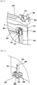
- FIG. 6 is a perspective view illustrating the upper fixture 220 of the oven door 100 according to an embodiment of the present invention.
- FIG. 7 is a perspective view illustrating the upper fixture 220 coupled to the front glass 120 of the oven door 100 according to an embodiment of the present invention.
- FIG. 7 illustrates the upper fixture 220 formed at a right portion of the oven door 100 at a front view.
- the upper fixture 220 formed at a left portion of the oven door 100 has the same shape and is coupled in the same way.
- the spacer 222 is formed on the portion of the upper fixture 220 contacting the front glass 120.
- a stopper 224 and a guide projection 226 are formed behind the spacer 222, that is, toward the rear glass 180.
- the spacer 222 is inserted into the through-hole 150 illustrated in FIG. 4 .
- the spacer 222 has a short tube shape. Referring to FIG. 6 , the spacer 222 upwardly protrudes from a top surface of the upper fixture 220. The top surface contacts the front glass 120. The stopper 224 downwardly protrudes from a bottom surface of a left bending portion of the upper fixture 220, that is, an opposite surface of the top surface.
- the stopper 224 restricts the assembly position of the space-ensuring member 500 described below.
- the stopper 224 contacts a right surface of the space-ensuring member 500 to prevent the space-ensuring member 500 from being pushed out toward right at the front view.
- the guide projection 226 is formed at a right side of the stopper 224 at the front view. Referring to FIG. 6 , the guide projection 226 downwardly protrudes more than two times than the stopper 224 does.
- the guide projection 226 restricts the position of the top shield member 400 described below.
- the guide projection 226 contacts the end of a top surface of the top shield member 400 to prevent the top shield member 400 from being upwardly released.
- the upper fixture 220 is attached by applying a silicon to a top surface of the left bending portion of the upper fixture 220, that is, the surface from which the spacer 222 protrudes, and then by inserting the spacer 222 into the through-hole 150 in the front glass 120.
- the door handle 122 is attached to the front glass 120 by putting the door handle 122 on the spacer inserted into the through-hole 150, and then by assembling the door handle 122 using a coupling member such as a screw "s".
- FIG. 8 is a partial perspective view illustrating the top shield member 400 and the middle frame 240 coupled to the upper fixture 220, and the reversed top cover 300 of the oven door 100 according to an embodiment of the present invention.
- the top cover 300 has a length corresponding to the distance between the upper fixtures 220 formed at the left and right portions of the front glass 120.
- a plurality of projections upwardly protrude from both sides of the top cover 300.
- the projections include a coupling portion 320 and a guide portion 340.
- the coupling portion 320 is coupled to the top cover 300 by a screw.
- the guide portion 340 upwardly protrudes with having inwardly a predetermined distance from the coupling portion 320.
- the coupling portion 320 upwardly protrudes from both sides of the top cover 300.
- a through-hole 322 is further formed in the coupling portion 320.
- the guide portion 340 having a half-length of that of the coupling portion 320 upwardly protrudes.
- the guide portion 340 contacts an upper portion of the space-ensuring members 500 when assembled.
- top shield member 400 is fit to an upper end of the heat-resisting glass 160. Both ends of the top shield member 400 contact the guide projection 226 of the upper fixtures 220. An upper end of the top shield member 400 contacts a bottom surface of the space-ensuring member 500 to be fixed.
- the lower fixture 260 is fixed to lower both ends of the front glass 120.
- FIG. 9 is a partial perspective view illustrating the lower fixture 260 coupled to the front glass 120 of the oven door 100 according to an embodiment of the present invention.
- a bottom surface of the lower fixture 260 is approximately flat.
- a large projection and a plurality of small projections upwardly protrude from the bottom surface.
- a fixing projection 261 and two guide projections 265 are formed on the bottom surface of the lower fixture 260.
- the fixing projection 261 protruding highest is coupled to the middle frame 240.
- the fixing projection 261 has a shape similar to " " at a top view.
- a rear projection 262 vertically protrudes from the bottom surface of the lower fixture 260.
- a side projection 263 horizontally protrudes from a lower middle portion of the rear projection 262 to an upper middle portion of the rear projection 262.
- the rear projection 262 and the side projection 263 are formed to be a single element.
- the fixing projection 261 is inserted into a rear insert groove 245 and a side insert groove 247, so that the middle frame 240 and the lower fixture 260 are coupled to each other.
- the rear and side insert grooves 245 and 247 are formed on the middle frame 240 which will be described below in detail.
- the guide projection 265 upwardly protruding has a small distance from the right side of the fixing projection 261.
- the two guide projections 265 having the same height have a distance from each other.
- the distance is slightly larger than the thickness of the division members 170, that is, the middle glass 140 and the heat-resisting glass 160, so that the division members 170 can be inserted, respectively.
- a plurality of guide holes 264 are formed in the lower fixture 260 by the guide projection 265.
- the guide holes 264 are divided by the guide projection 265.
- the middle glass 140 is inserted into the most rear space.
- the heat-resisting glass 160 is inserted in a space formed in front of the middle glass 140.
- the rear glass 180 is inserted in a space formed in front of the heat-resisting glass 160.
- the outer bracket 266 shields a front side of a space in which the rear glass 180 is placed, so that the rear glass 180 is guided to be inserted.
- the middle frame 240 is coupled to an upper portion of the lower fixture 260.
- FIG. 10 is a cross sectional view illustrating the disposition of the middle frame 240 of the oven door 100 according to an embodiment of the present invention.
- the middle frame 240 has a shape similar to " ⁇ ".
- the middle frame 240 includes a coupling portion 244, a shield portion 242, and an opening portion 246.
- the coupling portion 244 coupled to the rear projection 262 forms a middle portion of the middle frame 240.
- the shield portion 242 is extended under the coupling portion 244 and contacts the rear glass 180 to shield a side of a space between the rear glass 180 and the heat-resisting glass 160.
- the opening portion 246 is extended over the coupling portion 244 and contacts the fixing projection 261.
- a right portion of the coupling portion 244 has a shape similar to "U", so that the whole sides are closed except for a top side. Therefore, the right portion of the coupling portion 244 forms the rear insert groove 245 fit to the fixing projection 261 of the lower fixture 260.
- a left portion of the coupling portion 244 has a shape similar to "C” and forms a main body of the middle frame 240.
- the shield portion 242 is downwardly extended from a bottom surface of the left portion of the coupling portion 244 with a gentle slope, and then is bended to the right.
- the shield portion 242 has a shape similar to "L".
- the shield portion 242 contacts the rear glass 180.
- the shield portion 242 and the coupling portion 244 shield the side of the space between the rear glass 180 and the heat-resisting glass 160 with the coupling portion 244.
- the opening portion 246 having a shape similar to "L" is extended over the left portion of the coupling portion 244.
- the side insert groove 247 fit to the side projection 263 is formed between the opening portion 246 and the coupling portion 244.
- FIG. 11 is a cross sectional view illustrating the upper fixture 220 coupled to the middle frame 240 according to an embodiment of the present invention
- FIG. 12 is a cross sectional view illustrating an assembly of the middle frame 240, and the rear and side projection 262 and 263 of the lower fixture 260 according to an embodiment of the present invention.
- a side-sealing member 280 illustrated in dotted lines is formed between the middle frame 240 and the middle glass 140.
- the side-sealing member 280 is a tube formed of an elastic material, which has the same length as the middle frame 240 and is inserted between the middle frame 240 and the middle glass 140.
- the inner heater 10 is effectively insulated by the two spaces near the rear glass 180.
- the whole temperature of the oven door 100 may increase too high.
- the side of the space contacting the front glass 120 is open as illustrated in FIG. 12 so as to prevent the front glass 120 and the door handle 122 from being too hot. Users can touch the front glass 120 and the door handle 122 contacting the front glass 120.
- air introduced from the bottom of the oven door 100 to the space contacting the front glass 120 can go out through a side opening when heated.
- the door handle 122 is first attached. Silicon is applied to the top surface of the upper fixture 220, that is, the surface from which the spacer 222 protrudes so as to attach the door handle 122. After that, the spacer 222 is inserted to the through-hole 150 in the front glass 120 to fix the upper fixture 220 to the front glass 120.
- the spacer 222 has a height corresponding to the thickness of the front glass 120.
- the spacer 222 has a diameter slightly smaller than that of the through-hole 150.
- the spacer 222 having a tube shape has the height corresponding to the thickness of the front glass 120.
- the door handle 122 is placed on the front surface of the front glass 120 with the screw hole 124 being aligned with the through-hole 150.
- the screw “s” goes through the spacer 222 in the front glass 120 rotating in clock wise direction, so that the screw “s” is coupled to the screw hole 124 to couple the door handle 122 to the front glass 120.
- the spacer 222 and the upper fixture 220 form a single element to disperse the torque by the screw "s" along the whole upper fixture 220.
- the upper fixture 220 is coupled to the door handle 122 by the screw "s" with the front glass 120 being between the upper fixture 220 and the door handle 122.
- the lower fixture 260 is fixed to the lower both ends of the front glass 120.
- the lower fixture 260 is fixed having a vertical distance from the upper fixture 220, the distance being the length of the middle frame 240.
- the lower fixture 260 is strongly fixed to the lower portion of the front glass 120 with silicon being applied to a rear surface of the lower fixture 260.
- a screw can be used for stronger attachment.
- the middle frame 240 is formed between the upper and lower fixtures 220 and 260.
- the middle frame 240 is coupled with the fixing projection 261 formed on the lower fixture 260 being inserted into the rear insert groove 245 without a screw or sealant.
- the middle glass 120 is slantly inserted into the guide hole 264 formed in the lower fixture 260, and then an upper portion of the middle glass 120 is pushed down until the middle glass 120 is parallel with the front glass 120.
- the space-ensuring member 500 is inserted between the upper fixture 220 and the shield member 400.
- the side-sealing member 280 is inserted between the middle glass 140 and the middle frame 240.
- the side-sealing member 280 firmly fixes the middle glass 140 and the middle frame 240 as well as seals between the middle glass 140 and the middle frame 240.
- the heat-resisting glass 160 is inserted in the same way as the middle glass 140.
- the space-ensuring member 500 is located between the middle glass 140 and the heat-resisting glass 160 to form the space.
- the middle glass 140 and the heat-resisting glass 160 are firmly fixed by the space-ensuring member 500. Therefore, the space-ensuring member 500 prevents the middle glass 140 and the heat-resisting glass 160 from being damaged by impact.
- the top shield member 400 is fit to the heat-resisting glass 160.
- the top shield member 400 shields and insulates an upper side of the space between the heat-resisting glass 160 and the rear glass 180.
- the impact absorption material 420 formed at the both ends of the top shield member 400 is formed of an elastic material and contacts the guide projection 226 of the upper fixtures 220.
- the impact absorption material 420 prevents the edge of the top shield member 400 from scratching the heat-resisting and middle glasses 160 and 140.
- the rear glass 180 is placed behind the heat-resisting glass 160.
- the top cover 300 is located over the rear glass 180 to fix the rear glass 180.
- the guide portion 340 formed on both end portions of the top cover 300 contacts the upper portion of the space-ensuring members 500 to fix the space-ensuring members 500. Simultaneously, the guide portion 340 pushes down and fixes the top shield member 400. In addition, the guide portion 340 fixes the middle and heat-resisting glasses 140 and 160 since the space-ensuring members 500 and the top shield member 400 are coupled to the middle and heat-resisting glasses 140 and 160.
- the coupling portion 320 formed on the both end portions of the top cover 300 is coupled to the upper fixture 220 by a screw to obtain the oven door 100.
- the door frame is formed of the various parts. Therefore, when the middle frame 240 is damaged, only the middle frame 240 is replaced. As matter of course, the upper and lower fixtures 220 and 260 are individually replaced.
- air is introduced from the bottom of the oven door 100 and then is heated by a heat conduction and a radiation when the oven operates.
- the air goes out through only the side of the space between the front glass 120 and the middle glass 140 generated by the middle frame 240 of the rear glass 180.
- the space between the rear glass 180 and the heat-resisting glass 160 is closed, and the space between the front glass 120 and the middle glass 140 is opened when considering the shape and the assembly position of the middle frame 240. Therefore, the air introduced from the bottom of the oven door 100 goes out through only the side of the space contacting the front glass 120.
- An air introduction passage formed under the oven door 100 is connected to the spaces contacting the front and rear glasses 120 and 180. However, when an inner air is heated, the space contacting the rear glass 180 has no air outlet and thus is actually closed.
- the other parts except for the lower fixture 260 strongly attached to the front glass 120 are not under serious loads. Therefore, the other parts except for the lower fixture 260 and the front glass 120 are easily disassembled by unscrewing the screw "s" of the upper fixture 220.
- the middle frame 240 is very close to the rear glass 180 or actually contacts the rear glass 180 and relatively distant from the front glass 120. Therefore, air introduced from outside goes out through the space between the front glass 120 and the middle frame 240 to cool the front glass 120.
- the present invention covers the modifications and variations of this invention provided they come within the spirit and scope related to the assembly position of the middle frame 240.
- the air introduction passage formed under the oven door 100 is connected to the spaces contacting the front and rear glasses 120 and 180 and has no additional parts. Therefore, air introduced from outside is heated in the oven door 100, and then goes out through the space contacting the front glass 120.
- the present invention covers the modifications and variations of this invention provided they come within the broader spirit and scope of the present invention.
- the oven door according to the present invention includes the division members and the rear glass.
- the division members and the rear glass are easily coupled by the door frame, the space-ensuring member, and the top cover without additional brackets.
- the air introduced from the bottom of the oven door goes out through the space between the middle frame and the front glass, and thus effectively cools the front glass.
- the door frame including three parts is partially replaced when damaged.
- the shield frame for insulating is formed of a metal so that the thermal deformation of the shield frame is reduced.
- the spacer is used without an additional impact absorption washer when the door handle is coupled to the front glass.
- the spacer and the upper fixture form a single element to disperse the torque by the screw. Therefore, the front glass is not damaged, and the work effect for the assembly and the repair is improved. In addition, the problem of missing washers does not happen.
- the spacer formed the upper fixture and the through-hole of the front glass may have a tetragonal shape.
- the present invention covers the modifications and variations of this invention provided they come within the scope of the appended claims and their equivalents.
Landscapes
- Engineering & Computer Science (AREA)
- Chemical & Material Sciences (AREA)
- Combustion & Propulsion (AREA)
- Mechanical Engineering (AREA)
- General Engineering & Computer Science (AREA)
- Electric Ovens (AREA)
- Freezers Or Refrigerated Showcases (AREA)
Description
- The present invention relates to an oven door, and more particularly, to an oven door that is easily assembled/disassembled and conveniently used and provides selective insulation or selective cooling according to a coupling position and a coupling distance of each part. The present invention further relates to an oven door that can be applied to various heating apparatuses having a heater and a front hinge door.
- Two common kinds of modern ovens are gas ovens and electric ovens. The electric ovens are cooking apparatuses heating foods using heat generated by various heaters operated by electricity and an apparatus generating high frequency waves after the foods are placed in the ovens. Examples of heaters include ceramic heaters, sheath heaters, and halogen heaters. The electric ovens simultaneously heat the inside and the periphery of food to speed the cooking of the food and increase heat efficiency. In addition, the electric ovens are safe. Therefore, the electric ovens are widely used.
- The electric oven has a cubical shape and formed with a cavity in which food is cooked.
- In addition, a front opening of the oven cavity is selectively shielded by a rotatable oven door. A handle is formed at an upper portion of the oven door.
- The oven door formed in the front side of the oven is formed of a transparent material to allow a user to look into the inside of the oven where food is placed. In addition, the oven door is required to effectively preserve heat generated by the heater, while the oven door is required to reduce the temperature of parts exposed to the outside for convenient and safe use of the oven. In addition, the oven door is required to be easily assembled and disassembled for repairs. However, since the hinge oven door should include a transparent plate and a hinge structure, an oven door having such a hinge oven door is difficult to be conveniently used and assembled/disassembled and provide good insulation.
-
EP 1 076 210 A2 discloses an oven door, which comprises a front glass, and a rear glass between which division members are arranged. A middle frame is disposed at both side end portions of the division members and the rear glass. On the front glass a lower fixture is mounted on which the division member and the rear glass are arranged at intervals for restricting and supporting the rear glass and the division members in a load direction. A top cover is provided for restricting the front and rear glasses and the division member against the load direction. -
EP 0 549 933 A1 discloses an oven door for household ovens, which includes a series of three internal panels, which are mutually spaced by a first interspace and a second interspace. Upper and lower fixing elements are provided to support and restrict the internal panels in and against a load direction. The fixing elements are fixed to frame at the upper end of which a handle is provided. An external panel is supported by the frame. -
DE 198 53 758 A1 discloses another oven door having a front glass, an intermediate glass, and a rear glass, which are mounted to side frame elements so as to have predetermined intervals therebetween. A door handle is directly mounted to the front glass by means of a screw. -
DE 103 36 138 B3 discloses another oven door having a front glass on fixtures, which are mounted for supporting division members and a rear glass. A top cover is restricting the rear glass and the division members against the load direction. - The object underlying the present invention is to provide an oven door that can be easily assembled/disassembled and conveniently used, wherein the stress partly exerted on the front glass when opening and closing the door is minimized.
- This object is achieved by the oven door according to claim 1.
- Lower fixtures are formed on both lower side end portions of the front glass, and upper fixtures are formed on both upper side end portions of the front glass. The fixtures support and maintain the division members to have the distances from each other.
- A middle frame covers the both side end portions of the division members, and a top cover covers and fixes the division members.
- In here, inner parts except for fixtures including the division members, the middle frame, and the top cover are just placed on the lower fixture. The inner parts except for the the fixtures are easily disassembled by removing the top cover.
- In the oven door according to the present invention, air introduced from a bottom of the front glass goes out through a side of a narrow space between the middle frame and the front glass and thus cools the front glass. Therefore, when a user touches the door handle or the front glass, the user is safe from getting a burn.
- As a matter of course, a space contacting the rear glass has no air outlet, and thus insulates the inside of an oven.
- The oven door according to the present invention includes the door handle. The door handle minimizes the stress partially exerted on the front glass and is directly connected to the upper fixture. The assembly of the upper fixture, the front glass, and the door handle is more stably performed by a spacer formed on the upper fixture.
- The oven door according to the present invention insulates the inside of the oven. The air introduced from the bottom of the front glass goes out through the side of the space contacting the front glass and thus cools only the front glass. Since the heavy division members are supported by the lower fixture, the oven door can be easily assembled and disassembled.
- It is to be understood that both the foregoing general description and the following detailed description of the present invention are exemplary and explanatory and are intended to provide further explanation of the invention as claimed.
- The accompanying drawings, which are included to provide a further understanding of the invention and are incorporated in and constitute a part of this application, illustrate embodiment(s) of the invention and together with the description serve to explain the principle of the invention. In the drawings:
-
FIG. 1 is an perspective view illustrating an oven according to an embodiment of the present invention; -
FIG. 2 is a perspective view illustrating an oven door according to an embodiment of the present invention; -
FIG. 3 is an exploded perspective view illustrating an oven door according to an embodiment of the present invention; -
FIG. 4 is an exploded perspective view illustrating a front glass of an oven door according to an embodiment of the present invention; -
FIG. 5 is an exploded perspective view illustrating a door frame of an oven door according to an embodiment of the present invention; -
FIG. 6 is a perspective view illustrating an upper fixture of an oven door according to an embodiment of the present invention; -
FIG. 7 is a partial perspective view illustrating an upper fixture coupled to a front glass of an oven door according to an embodiment of the present invention; -
FIG. 8 is a partial perspective view illustrating a top shield member and a middle frame coupled to an upper fixture, and a reversed top cover of an oven door according to an embodiment of the present invention; -
FIG. 9 is a partial perspective view illustrating a lower fixture coupled to a front glass of an oven door according to an embodiment of the present invention; -
FIG. 10 is a cross sectional view illustrating the disposition of a middle frame, a front glass, a rear glass, and an inside division members of an over door according to an embodiment of the present invention; -
FIG. 11 is a cross sectional view illustrating an upper fixture coupled to a middle frame according to an embodiment of the present invention; and -
FIG. 12 is a cross sectional view illustrating an assembly of a middle frame, a side-sealing member, and a lower fixture according to an embodiment of the present invention. - Reference will now be made in detail to the preferred embodiments of the present invention, examples of which are illustrated in the accompanying drawings.
-
FIG. 1 is a perspective view illustrating an oven according to an embodiment of the present invention - Referring to
FIG. 1 , the oven includes aninner heater 20, amain body 10, and anoven door 100. Themain body 10 includes acontrol panel 30. Theoven door 100 includes a transparent window so as to check the state of a food in themain body 10. Thehinge oven door 100 is coupled to themain body 10. Adoor handle 122 is formed in an upper portion of a front surface of theoven door 100. -
FIG. 2 is a perspective view illustrating theoven door 100 according to an embodiment of the present invention. - Referring to
FIG. 2 , theoven door 100 according to the present invention includes afront glass 120, atop cover 300,door frames 200, and arear glass 180. Thefront glass 120 makes a front appearance. Thetop cover 300 formed on an upper portion of a rear surface of thefront glass 120 makes a top appearance of theoven door 100. Thedoor frame 200 formed on rear both sides of thefront glass 120 supports thefront glass 120 and makes a side appearance of theoven door 100. Therear glass 180 fixed by thedoor frame 200 and thetop cover 300 makes a rear appearance of theoven door 100. - The
front glass 120 having a tetragonal shape is formed at the most front portion of theoven door 100. Thefront glass 120 is the main appearance of an oven. Therefore, thefront glass 120 is coated for improving the appearance and preventing damages such as scratches. In addition, thedoor handle 122 is coupled to an upper portion of a front surface of thefront glass 120. - Users hold the
door handle 122 to open and close theoven door 100. Thedoor handle 122 is a bar having a convex curvature. In addition, ascrew hole 124 is further formed in both ends of thedoor handle 122 for the assembly using a screw. - In addition, a through-
hole 150 illustrated inFIG. 4 is formed in an upper portion of thefront glass 120. A coupling member such as the screw goes through the through-hole 150, and aspacer 222 described below is inserted into the through-hole 150. - Meanwhile, the
door frame 200 is formed on both sides of thefront glass 120. Thedoor frame 200 includes three portions and has a long cubic shape to make the side appearance of theoven door 100. - The
door frame 200 includesupper fixtures 220, amiddle frame 240, and alower fixture 260. Theupper fixture 220 forms an upper portion of thedoor frame 200, themiddle frame 240 forms a middle portion of thedoor frame 200, and thelower fixture 260 forms a lower portion of thedoor frame 200. - Meanwhile, the
rear glass 180 forms a rear surface of theoven door 100. - The
rear glass 180 is formed at the most rear portion of theoven door 100 to contact an oven cavity (not shown) in which foods are cooked. Therear glass 180 is exposed to relatively high heat. Therefore, therear glass 180 may be coated or specially treated so as to resist heat. Furthermore, a space contacting therear glass 180 is completely sealed regardless of a space contacting thefront glass 120, and thus increases an insulation effect as much as possible. -
FIGS. 3 and4 are exploded perspective views illustrating theoven door 100 according to an embodiment of the present invention.FIG. 5 is an exploded perspective view illustrating thedoor frame 200 of theoven door 100 according to an embodiment of the present invention. - Referring to
FIGS. 3 through 5 , theoven door 100 further includes adivision member 170, atop shield member 400, and a couple of space-ensuringmembers 500. Thedivision member 170 is formed between thefront glass 120 and therear glass 180. Thetop shield member 400 shields a top side of thedivision members 170. The space-ensuringmember 500 detaches thefront glass 120 from thedivision members 170 to prevent damages from impact. - In addition, the
division member 170 is formed between the door frames 200. The door frames 200 are formed at a left and right portions of the rear surface of thefront glass 120, respectively. Thedivision member 170 includes a heat-resistingglass 160 and amiddle glass 140. The heat-resistingglass 160 is detached from therear glass 180 to form a predetermined space. Themiddle glass 140 formed between the heat-resistingglass 160 and thefront glass 120 forms separated spaces between the heat-resistingglass 160 and thefront glass 120. - The
top shield member 400 is required to have an excellent insulation performance and excellent strength. For example, thetop shield member 400 may be a metal bar. An upper end of the heat-resistingglass 160 of thedivision members 170 is inserted into thetop shield member 400 without an additional coupling member. Thetop shield member 400 further includes a groove (not shown) having a size corresponding to the thickness of the heat-resistingglass 160. - In addition, an
impact absorption material 420 is formed at both ends of thetop shield member 400. Referring toFIG. 8 , it is intuited how thetop shield member 400 is coupled to the heat-resistingglass 160. - In addition, the space-ensuring
member 500 includes a tetragonal plate and a projection. The tetragonal plate and the projection are formed to be a single element. The projection downwardly protrudes from a middle portion of the tetragonal plate. The couple of space-ensuringmembers 500 have a shape similar to "" at a side view. The space-ensuringmembers 500 are inserted between themiddle glass 140 and the heat-resistingglass 160. The space-ensuringmembers 500 are at left and right portions of theglasses - Meanwhile, the
oven door 100 including the parts as described above is assembled using thedoor frame 200 as a reference part. - Among the parts of the
door frame 200, theupper fixture 220 is fixed to the upper portion of the rear surface of thefront glass 120 using a coupling member such as a sealant and a screw. Thespacer 222 is formed on a portion of theupper fixture 220 contacting thefront glass 120. Thespacer 222 prevents thefront glass 120 from being damaged by impact when thefront glass 120 is coupled to thedoor handle 122 by a coupling member such as a screw. Thespacer 222 and theupper fixture 220 are a single element. -
FIG. 6 is a perspective view illustrating theupper fixture 220 of theoven door 100 according to an embodiment of the present invention.FIG. 7 is a perspective view illustrating theupper fixture 220 coupled to thefront glass 120 of theoven door 100 according to an embodiment of the present invention. -
FIG. 7 illustrates theupper fixture 220 formed at a right portion of theoven door 100 at a front view. Theupper fixture 220 formed at a left portion of theoven door 100 has the same shape and is coupled in the same way. - The
spacer 222 is formed on the portion of theupper fixture 220 contacting thefront glass 120. Astopper 224 and aguide projection 226 are formed behind thespacer 222, that is, toward therear glass 180. - As described above, the
spacer 222 is inserted into the through-hole 150 illustrated inFIG. 4 . Thespacer 222 has a short tube shape. Referring toFIG. 6 , thespacer 222 upwardly protrudes from a top surface of theupper fixture 220. The top surface contacts thefront glass 120. Thestopper 224 downwardly protrudes from a bottom surface of a left bending portion of theupper fixture 220, that is, an opposite surface of the top surface. - The
stopper 224 restricts the assembly position of the space-ensuringmember 500 described below. Thestopper 224 contacts a right surface of the space-ensuringmember 500 to prevent the space-ensuringmember 500 from being pushed out toward right at the front view. - In addition, the
guide projection 226 is formed at a right side of thestopper 224 at the front view. Referring toFIG. 6 , theguide projection 226 downwardly protrudes more than two times than thestopper 224 does. - The
guide projection 226 restricts the position of thetop shield member 400 described below. Theguide projection 226 contacts the end of a top surface of thetop shield member 400 to prevent thetop shield member 400 from being upwardly released. - The
upper fixture 220 is attached by applying a silicon to a top surface of the left bending portion of theupper fixture 220, that is, the surface from which thespacer 222 protrudes, and then by inserting thespacer 222 into the through-hole 150 in thefront glass 120. - The
door handle 122 is attached to thefront glass 120 by putting thedoor handle 122 on the spacer inserted into the through-hole 150, and then by assembling thedoor handle 122 using a coupling member such as a screw "s". -
FIG. 8 is a partial perspective view illustrating thetop shield member 400 and themiddle frame 240 coupled to theupper fixture 220, and the reversedtop cover 300 of theoven door 100 according to an embodiment of the present invention. - Referring to
FIG. 8 , thetop cover 300 has a length corresponding to the distance between theupper fixtures 220 formed at the left and right portions of thefront glass 120. A plurality of projections upwardly protrude from both sides of thetop cover 300. In addition, the projections include acoupling portion 320 and aguide portion 340. Thecoupling portion 320 is coupled to thetop cover 300 by a screw. Theguide portion 340 upwardly protrudes with having inwardly a predetermined distance from thecoupling portion 320. - The
coupling portion 320 upwardly protrudes from both sides of thetop cover 300. A through-hole 322 is further formed in thecoupling portion 320. - The
guide portion 340 having a half-length of that of thecoupling portion 320 upwardly protrudes. Theguide portion 340 contacts an upper portion of the space-ensuringmembers 500 when assembled. - In addition, the
top shield member 400 is fit to an upper end of the heat-resistingglass 160. Both ends of thetop shield member 400 contact theguide projection 226 of theupper fixtures 220. An upper end of thetop shield member 400 contacts a bottom surface of the space-ensuringmember 500 to be fixed. - Meanwhile, the
lower fixture 260 is fixed to lower both ends of thefront glass 120. -
FIG. 9 is a partial perspective view illustrating thelower fixture 260 coupled to thefront glass 120 of theoven door 100 according to an embodiment of the present invention. Referring toFIG. 9 , a bottom surface of thelower fixture 260 is approximately flat. A large projection and a plurality of small projections upwardly protrude from the bottom surface. - In detail, a fixing
projection 261 and twoguide projections 265 are formed on the bottom surface of thelower fixture 260. The fixingprojection 261 protruding highest is coupled to themiddle frame 240. Theguide projection 265 protrudes with having one-tenth length of the fixingprojection 261. - The fixing
projection 261 has a shape similar to "" at a top view. A
rear projection 262 vertically protrudes from the bottom surface of thelower fixture 260. Aside projection 263 horizontally protrudes from a lower middle portion of therear projection 262 to an upper middle portion of therear projection 262. Therear projection 262 and theside projection 263 are formed to be a single element. In addition, the fixingprojection 261 is inserted into arear insert groove 245 and aside insert groove 247, so that themiddle frame 240 and thelower fixture 260 are coupled to each other. The rear and side insertgrooves middle frame 240 which will be described below in detail. - The
guide projection 265 upwardly protruding has a small distance from the right side of the fixingprojection 261. The twoguide projections 265 having the same height have a distance from each other. The distance is slightly larger than the thickness of thedivision members 170, that is, themiddle glass 140 and the heat-resistingglass 160, so that thedivision members 170 can be inserted, respectively. - A plurality of guide holes 264 are formed in the
lower fixture 260 by theguide projection 265. The guide holes 264 are divided by theguide projection 265. Themiddle glass 140 is inserted into the most rear space. - In addition, the heat-resisting
glass 160 is inserted in a space formed in front of themiddle glass 140. Therear glass 180 is inserted in a space formed in front of the heat-resistingglass 160. - Therefore, the outer bracket 266 shields a front side of a space in which the
rear glass 180 is placed, so that therear glass 180 is guided to be inserted. - Meanwhile, the
middle frame 240 is coupled to an upper portion of thelower fixture 260. -
FIG. 10 is a cross sectional view illustrating the disposition of themiddle frame 240 of theoven door 100 according to an embodiment of the present invention. - Referring to
FIG. 10 , themiddle frame 240 has a shape similar to "⊦". Themiddle frame 240 includes acoupling portion 244, ashield portion 242, and anopening portion 246. Thecoupling portion 244 coupled to therear projection 262 forms a middle portion of themiddle frame 240. Theshield portion 242 is extended under thecoupling portion 244 and contacts therear glass 180 to shield a side of a space between therear glass 180 and the heat-resistingglass 160. Theopening portion 246 is extended over thecoupling portion 244 and contacts the fixingprojection 261. - A right portion of the
coupling portion 244 has a shape similar to "U", so that the whole sides are closed except for a top side. Therefore, the right portion of thecoupling portion 244 forms therear insert groove 245 fit to the fixingprojection 261 of thelower fixture 260. In addition, a left portion of thecoupling portion 244 has a shape similar to "C" and forms a main body of themiddle frame 240. - The
shield portion 242 is downwardly extended from a bottom surface of the left portion of thecoupling portion 244 with a gentle slope, and then is bended to the right. Theshield portion 242 has a shape similar to "L". - The
shield portion 242 contacts therear glass 180. Theshield portion 242 and thecoupling portion 244 shield the side of the space between therear glass 180 and the heat-resistingglass 160 with thecoupling portion 244. - The
opening portion 246 having a shape similar to "L" is extended over the left portion of thecoupling portion 244. In addition, theside insert groove 247 fit to theside projection 263 is formed between the openingportion 246 and thecoupling portion 244. -
FIG. 11 is a cross sectional view illustrating theupper fixture 220 coupled to themiddle frame 240 according to an embodiment of the present invention, andFIG. 12 is a cross sectional view illustrating an assembly of themiddle frame 240, and the rear andside projection lower fixture 260 according to an embodiment of the present invention. - Referring to
FIG. 12 , a side-sealingmember 280 illustrated in dotted lines is formed between themiddle frame 240 and themiddle glass 140. The side-sealingmember 280 is a tube formed of an elastic material, which has the same length as themiddle frame 240 and is inserted between themiddle frame 240 and themiddle glass 140. - Referring to
FIGS. 10 and12 , only the space between therear glass 180 and the heat-resistingglass 160 and the space between the heat-resistingglass 160 and themiddle glass 140 are sealed by the side-sealingmember 280 and themiddle frame 240. The space between themiddle glass 140 and thefront glass 120, that is, the side of the space contacting thefront glass 120 is not sealed. - This is an important technology. The
inner heater 10 is effectively insulated by the two spaces near therear glass 180. - In the structure of the
oven door 100, the whole temperature of theoven door 100 may increase too high. According to the present invention, the side of the space contacting thefront glass 120 is open as illustrated inFIG. 12 so as to prevent thefront glass 120 and thedoor handle 122 from being too hot. Users can touch thefront glass 120 and thedoor handle 122 contacting thefront glass 120. - Referring to
FIG. 12 , air introduced from the bottom of theoven door 100 to the space contacting thefront glass 120 can go out through a side opening when heated. - Therefore, when a user touch the
door handle 122 or thefront glass 120 after a long cooking, the user is safe from getting a burn. - Hereinafter, functions of the various parts will be described while assembling the
oven door 100 with reference toFIGS. 3 and4 . - In an assembly process of the
oven door 100 according to the present invention, thedoor handle 122 is first attached. Silicon is applied to the top surface of theupper fixture 220, that is, the surface from which thespacer 222 protrudes so as to attach thedoor handle 122. After that, thespacer 222 is inserted to the through-hole 150 in thefront glass 120 to fix theupper fixture 220 to thefront glass 120. - In here, the
spacer 222 has a height corresponding to the thickness of thefront glass 120. Thespacer 222 has a diameter slightly smaller than that of the through-hole 150. - In addition, the
spacer 222 having a tube shape has the height corresponding to the thickness of thefront glass 120. - After the
upper fixture 220 is attached to the rear surface of thefront glass 120, thedoor handle 122 is placed on the front surface of thefront glass 120 with thescrew hole 124 being aligned with the through-hole 150. In addition, the screw "s" goes through thespacer 222 in thefront glass 120 rotating in clock wise direction, so that the screw "s" is coupled to thescrew hole 124 to couple thedoor handle 122 to thefront glass 120. - The
spacer 222 and theupper fixture 220 form a single element to disperse the torque by the screw "s" along the wholeupper fixture 220. Theupper fixture 220 is coupled to thedoor handle 122 by the screw "s" with thefront glass 120 being between theupper fixture 220 and thedoor handle 122. - After that, the
lower fixture 260 is fixed to the lower both ends of thefront glass 120. Thelower fixture 260 is fixed having a vertical distance from theupper fixture 220, the distance being the length of themiddle frame 240. In addition, thelower fixture 260 is strongly fixed to the lower portion of thefront glass 120 with silicon being applied to a rear surface of thelower fixture 260. In addition, a screw can be used for stronger attachment. - The
middle frame 240 is formed between the upper andlower fixtures middle frame 240 is coupled with the fixingprojection 261 formed on thelower fixture 260 being inserted into therear insert groove 245 without a screw or sealant. - After the upper and
lower fixtures middle frame 240 are fixed to thefront glass 120, a lower portion of themiddle glass 120 is slantly inserted into theguide hole 264 formed in thelower fixture 260, and then an upper portion of themiddle glass 120 is pushed down until themiddle glass 120 is parallel with thefront glass 120. In addition, the space-ensuringmember 500 is inserted between theupper fixture 220 and theshield member 400. - Meanwhile, the side-sealing
member 280 is inserted between themiddle glass 140 and themiddle frame 240. The side-sealingmember 280 firmly fixes themiddle glass 140 and themiddle frame 240 as well as seals between themiddle glass 140 and themiddle frame 240. - The heat-resisting
glass 160 is inserted in the same way as themiddle glass 140. - In here, the space-ensuring
member 500 is located between themiddle glass 140 and the heat-resistingglass 160 to form the space. Themiddle glass 140 and the heat-resistingglass 160 are firmly fixed by the space-ensuringmember 500. Therefore, the space-ensuringmember 500 prevents themiddle glass 140 and the heat-resistingglass 160 from being damaged by impact. - After the heat-resisting
glass 160 is inserted, thetop shield member 400 is fit to the heat-resistingglass 160. Thetop shield member 400 shields and insulates an upper side of the space between the heat-resistingglass 160 and therear glass 180. - In addition, the
impact absorption material 420 formed at the both ends of thetop shield member 400 is formed of an elastic material and contacts theguide projection 226 of theupper fixtures 220. - When the
top shield member 400 is formed of a metal, theimpact absorption material 420 prevents the edge of thetop shield member 400 from scratching the heat-resisting andmiddle glasses - After the
top shield member 400 is fit, therear glass 180 is placed behind the heat-resistingglass 160. In addition, thetop cover 300 is located over therear glass 180 to fix therear glass 180. - In here, the
guide portion 340 formed on both end portions of thetop cover 300 contacts the upper portion of the space-ensuringmembers 500 to fix the space-ensuringmembers 500. Simultaneously, theguide portion 340 pushes down and fixes thetop shield member 400. In addition, theguide portion 340 fixes the middle and heat-resistingglasses members 500 and thetop shield member 400 are coupled to the middle and heat-resistingglasses - In addition, the
coupling portion 320 formed on the both end portions of thetop cover 300 is coupled to theupper fixture 220 by a screw to obtain theoven door 100. - The door frame is formed of the various parts. Therefore, when the
middle frame 240 is damaged, only themiddle frame 240 is replaced. As matter of course, the upper andlower fixtures - In the
oven door 100, air is introduced from the bottom of theoven door 100 and then is heated by a heat conduction and a radiation when the oven operates. The air goes out through only the side of the space between thefront glass 120 and themiddle glass 140 generated by themiddle frame 240 of therear glass 180. - That is, the space between the
rear glass 180 and the heat-resistingglass 160 is closed, and the space between thefront glass 120 and themiddle glass 140 is opened when considering the shape and the assembly position of themiddle frame 240. Therefore, the air introduced from the bottom of theoven door 100 goes out through only the side of the space contacting thefront glass 120. - An air introduction passage formed under the
oven door 100 is connected to the spaces contacting the front andrear glasses rear glass 180 has no air outlet and thus is actually closed. - Referring to
FIG. 3 , the other parts except for thelower fixture 260 strongly attached to thefront glass 120 are not under serious loads. Therefore, the other parts except for thelower fixture 260 and thefront glass 120 are easily disassembled by unscrewing the screw "s" of theupper fixture 220. - In addition, according to the spirit and scope related to the assembly position of the characteristic
middle frame 240 of the present invention, themiddle frame 240 is very close to therear glass 180 or actually contacts therear glass 180 and relatively distant from thefront glass 120. Therefore, air introduced from outside goes out through the space between thefront glass 120 and themiddle frame 240 to cool thefront glass 120. Thus, it is intended that the present invention covers the modifications and variations of this invention provided they come within the spirit and scope related to the assembly position of themiddle frame 240. According to the broader spirit and scope of the present invention, the air introduction passage formed under theoven door 100 is connected to the spaces contacting the front andrear glasses oven door 100, and then goes out through the space contacting thefront glass 120. Thus, it is intended that the present invention covers the modifications and variations of this invention provided they come within the broader spirit and scope of the present invention. - As described above, the oven door according to the present invention includes the division members and the rear glass. The division members and the rear glass are easily coupled by the door frame, the space-ensuring member, and the top cover without additional brackets.
- The air introduced from the bottom of the oven door goes out through the space between the middle frame and the front glass, and thus effectively cools the front glass.
- The door frame including three parts is partially replaced when damaged. The shield frame for insulating is formed of a metal so that the thermal deformation of the shield frame is reduced.
- The spacer is used without an additional impact absorption washer when the door handle is coupled to the front glass. The spacer and the upper fixture form a single element to disperse the torque by the screw. Therefore, the front glass is not damaged, and the work effect for the assembly and the repair is improved. In addition, the problem of missing washers does not happen.
- It will be apparent to those skilled in the art that various modifications and variations can be made in the present invention. For example, the spacer formed the upper fixture and the through-hole of the front glass may have a tetragonal shape. Thus, it is intended that the present invention covers the modifications and variations of this invention provided they come within the scope of the appended claims and their equivalents.
Claims (9)
- An oven (100) door comprising:- a plurality of division members (170) arranged in the oven door at predetermined intervals;- a front glass (120) and a rear glass (180) disposed in front and rear of the division members (170), respectively;- a middle frame (240) disposed at both side end portions of the division members (170);- a lower fixture (260) on which the front and rear glasses (120, 180) and the division member (170) are arranged at intervals, the lower fixture (260) restricting and supporting the front and rear glasses (120, 180) and the division members (170) in a load direction; and- a top cover (300) restricting the front and rear glasses (120, 180) and the division members (170) against the load direction;characterized in that the oven door (100) further comprises:- an upper fixture (220) coupled to the front glass (120) and maintaining the division members (170) to have the distances from each other; and- a door handle (122) coupled to the upper fixture by a screw (S) going through the front glass (120).
- The oven door according to claim 1, further comprising:- a top shield member (400) coupled to the upper fixture (220) and shielding heat emitted from the division members (170); and- a space-ensuring member (500) guiding and fixing a horizontal position of the top shield member (400) and separating the division members (170).
- The oven door according to claim 1, wherein the top cover (300) completely surrounds upper surface portions of the front and rear glasses (120, 180) and both side end portions of the upper surface portions.
- The oven door according to claim 1, wherein the lower fixture (260) completely surrounds a lower side end portion of rear glass (180) and the division members (170).
- The oven door according to claim 1, wherein the middle frame (240) covers a side end portion of the division members (170) and has a distance from the front glass (120).
- The oven door according to claim 1, further comprising a side-sealing member (280) inserted between one of the division members (170) and the middle frame (240) for providing sealing.
- The oven door according to claim 1, wherein the upper fixture (220) further comprises a spacer (222) going through the front glass (120) and contacting the door handle (122).
- The oven door according to claim 7, wherein the spacer (222) has a tube shape with a thickness equal to or larger than that of the front glass (120), the spacer (222) having a diameter that increases when pressed in a longitudinal direction.
- The oven door according to claim 7, wherein one of the door handle (122) and the upper fixture (220) has an area contacting the front glass (120), the area being sufficiently larger than an area of the front glass (120) through which the upper fixture goes through.
Applications Claiming Priority (2)
| Application Number | Priority Date | Filing Date | Title |
|---|---|---|---|
| KR20060036638 | 2006-04-24 | ||
| KR1020060041051A KR100722054B1 (en) | 2006-05-08 | 2006-05-08 | Oven Door Structure |
Publications (3)
| Publication Number | Publication Date |
|---|---|
| EP1850072A2 EP1850072A2 (en) | 2007-10-31 |
| EP1850072A3 EP1850072A3 (en) | 2013-07-17 |
| EP1850072B1 true EP1850072B1 (en) | 2017-03-01 |
Family
ID=38325306
Family Applications (1)
| Application Number | Title | Priority Date | Filing Date |
|---|---|---|---|
| EP07008211.0A Not-in-force EP1850072B1 (en) | 2006-04-24 | 2007-04-23 | Oven door |
Country Status (4)
| Country | Link |
|---|---|
| US (1) | US7703451B2 (en) |
| EP (1) | EP1850072B1 (en) |
| CN (1) | CN101063532B (en) |
| AU (1) | AU2007201803B2 (en) |
Families Citing this family (37)
| Publication number | Priority date | Publication date | Assignee | Title |
|---|---|---|---|---|
| EP2108892B1 (en) * | 2008-04-10 | 2015-09-02 | Whirlpool Corporation | Built-in oven |
| EP2108889B1 (en) * | 2008-04-10 | 2015-09-02 | Whirlpool Corporation | Full glass oven door |
| CA2761792A1 (en) * | 2009-05-14 | 2010-11-18 | Schott Gemtron Corporation | Full-view oven doors having locking mechanisms |
| EP2362150B1 (en) | 2010-02-26 | 2017-05-10 | Electrolux Home Products Corporation N.V. | An oven door for a domestic cooking oven |
| EP2386800B1 (en) * | 2010-05-14 | 2016-09-28 | Electrolux Home Products Corporation N.V. | A door for a domestic appliance |
| DE102010063936A1 (en) * | 2010-12-22 | 2012-06-28 | BSH Bosch und Siemens Hausgeräte GmbH | Household appliance door |
| US9016270B2 (en) * | 2011-01-05 | 2015-04-28 | General Electric Company | Window mounting for thermal expansion in an oven appliance |
| EP2574851B1 (en) * | 2011-09-27 | 2016-06-29 | Miele & Cie. KG | Cooking device door and cooking device |
| WO2013164464A2 (en) * | 2012-05-03 | 2013-11-07 | Electrolux Home Products Corporation N. V. | An arrangement of glass panels for a heat insulated oven door for a cooking oven |
| US9429329B2 (en) * | 2012-05-31 | 2016-08-30 | Bsh Home Appliances Corporation | Household appliance having a mounting system for a middle door glass |
| US9958166B2 (en) * | 2012-05-31 | 2018-05-01 | Bsh Home Appliances Corporation | Household appliance having a latch retainer for an all glass inner door |
| US9822983B2 (en) * | 2012-05-31 | 2017-11-21 | Bsh Home Appliances Corporation | Self-cleaning household appliance having a range door with a full glass inner surface |
| CN102808568B (en) * | 2012-07-25 | 2014-10-08 | 杭州老板电器股份有限公司 | Electric oven furnace door structure with heat-insulating wall technology |
| EP2731404B1 (en) * | 2012-11-12 | 2020-04-08 | Electrolux Home Products Corporation N.V. | An oven door for a microwave oven or a multifunctional oven with microwave heating function |
| US10495305B2 (en) | 2012-11-19 | 2019-12-03 | Whirlpool Corporation | Oven door assembly |
| EP2938930B1 (en) | 2012-12-28 | 2017-08-02 | Arçelik Anonim Sirketi | A door comprising detachable panels and an oven wherein the door is used |
| US20140304944A1 (en) * | 2013-04-10 | 2014-10-16 | Bsh Home Appliances Corporation | Home appliance with handle, end cap, and crush rib |
| DE102014216554A1 (en) * | 2014-03-19 | 2015-09-24 | BSH Hausgeräte GmbH | Door for a household appliance with a connecting element comprising a centering element, household appliance with such a door and method for mounting a door |
| US10145565B2 (en) * | 2014-04-08 | 2018-12-04 | Whirlpool Emea S.P.A. | Door for a domestic cooking oven |
| WO2015165499A1 (en) * | 2014-04-29 | 2015-11-05 | Arcelik Anonim Sirketi | Door with improved disassembly/reassembly for use in an oven |
| US9513015B2 (en) | 2014-06-19 | 2016-12-06 | Dacor | Oven with control panel cooling system |
| CN105317340A (en) * | 2014-08-05 | 2016-02-10 | 广东美的厨房电器制造有限公司 | Oven firedoor and oven |
| CN104847198B (en) * | 2015-03-31 | 2017-01-04 | 广东美的厨房电器制造有限公司 | Buckle mounting structure, snap component and household electrical appliance |
| EP3104084A1 (en) * | 2015-06-08 | 2016-12-14 | Whirlpool Corporation | Domestic oven |
| EP3118525B1 (en) * | 2015-07-17 | 2018-03-21 | Electrolux Appliances Aktiebolag | Oven door for an oven cavity of a cooking oven |
| ITUB20152351A1 (en) * | 2015-07-21 | 2017-01-21 | Tecno Spa | OVEN DOOR |
| KR102458437B1 (en) | 2015-08-04 | 2022-10-26 | 삼성전자주식회사 | Oven |
| EP3246632B1 (en) * | 2016-05-19 | 2020-02-26 | Electrolux Appliances Aktiebolag | Domestic appliance comprising a door |
| DE102016224755A1 (en) * | 2016-12-12 | 2018-06-14 | BSH Hausgeräte GmbH | Haushaltsgargerät |
| CN107136948B (en) * | 2017-04-17 | 2023-07-25 | 中山百得厨卫有限公司 | Oven door convenient to install |
| CN107726370B (en) * | 2017-10-27 | 2019-02-01 | 华北水利水电大学 | The anti-scald door body of separation of glasses formula warming stove |
| DE102017220217A1 (en) * | 2017-11-14 | 2019-05-16 | BSH Hausgeräte GmbH | Door for a cooking appliance with specific front-side sealing downwards, as well as cooking appliance |
| US10782028B2 (en) * | 2017-11-15 | 2020-09-22 | Bsh Home Appliances Corporation | Glass on outside of range door |
| US10240378B1 (en) | 2018-05-16 | 2019-03-26 | Bartolomeo Puccio | Oven cover system |
| JP7086791B2 (en) * | 2018-08-29 | 2022-06-20 | 日立グローバルライフソリューションズ株式会社 | Cooker |
| TR201820666A2 (en) * | 2018-12-27 | 2020-07-21 | Bsh Ev Aletleri San Ve Tic As | ONE DOOR FOR HOME APPLIANCE |
| DE102024203574A1 (en) * | 2024-04-17 | 2025-10-23 | BSH Hausgeräte GmbH | Lid for household cooking appliance and household cooking appliance with cooking drawer |
Family Cites Families (49)
| Publication number | Priority date | Publication date | Assignee | Title |
|---|---|---|---|---|
| US1664443A (en) * | 1925-08-13 | 1928-04-03 | Williams Oven Mfg Company | Oven |
| US2012549A (en) * | 1933-12-13 | 1935-08-27 | Rottersmann Henry | Baking oven |
| US2231514A (en) * | 1939-06-15 | 1941-02-11 | Adlake Co | Double glass sash |
| US2961694A (en) * | 1957-07-09 | 1960-11-29 | American Art Metals Company | Door handle assembly |
| US3326201A (en) * | 1964-07-30 | 1967-06-20 | Edgar N Murray | Barbecue apparatus |
| US3267930A (en) * | 1964-09-29 | 1966-08-23 | Tappan Co | Oven door with panel inserts |
| US3818890A (en) * | 1973-07-16 | 1974-06-25 | Gen Motors Corp | Ventilated windowed oven door |
| US3855994A (en) * | 1973-07-16 | 1974-12-24 | Gen Motors Corp | Ventilated windowed oven door |
| US3859499A (en) * | 1974-06-12 | 1975-01-07 | Gen Motors Corp | Airflow cooling system for heat-cleaning ranges |
| US3991738A (en) * | 1975-01-22 | 1976-11-16 | Shatterproof Glass Corporation | Oven doors |
| US4206338A (en) * | 1976-02-12 | 1980-06-03 | Mills Products, Inc. | Self-contained window unit for oven doors (common cavity) |
| US4023554A (en) * | 1976-02-12 | 1977-05-17 | Mills Products, Inc. | Self-contained window unit for oven doors |
| CA1056680A (en) * | 1976-04-12 | 1979-06-19 | Claude Drouin | Window unit for use in oven doors |
| US4043091A (en) * | 1976-06-04 | 1977-08-23 | Mills Products, Inc. | Flange mount oven door window |
| US4253286A (en) * | 1978-10-26 | 1981-03-03 | Katona Joseph W | Clip-aire oven door window |
| US4353351A (en) * | 1979-03-08 | 1982-10-12 | Cagle Bunyan B | Solid fuel furnace |
| US4313418A (en) * | 1980-03-18 | 1982-02-02 | Janice E. Schrader | Damper control |
| US4390767A (en) * | 1981-01-28 | 1983-06-28 | Amana Refrigeration, Inc. | Windowed and choked combination oven door |
| US4383519A (en) * | 1981-06-10 | 1983-05-17 | Mills Products, Inc. | Door frame and handle combination |
| US4613530A (en) * | 1984-11-01 | 1986-09-23 | Southwall Technologies, Inc. | Multiple pane glass unit with electrically conductive transparent film for use as radiation shield |
| US4912809A (en) * | 1985-01-11 | 1990-04-03 | Kawneer Company, Inc. | Tandem cone bolt anchor mounting assembly |
| US4638529A (en) * | 1985-07-05 | 1987-01-27 | Mills Products, Inc. | Handle construction |
| IT1187285B (en) * | 1985-07-15 | 1987-12-23 | Zanussi Elettrodomestici | DOOR FOR OVEN, IN PARTICULAR OF THE VENTILATED TYPE |
| US4732431A (en) * | 1986-05-21 | 1988-03-22 | Whirlpool Corporation | Interchangeable door panels for dishwasher |
| DE8912976U1 (en) * | 1989-11-02 | 1991-03-07 | Bosch-Siemens Hausgeräte GmbH, 8000 München | Oven door |
| US5088470A (en) * | 1991-02-27 | 1992-02-18 | W.C. Bradley Company | Access window for barbecue grills |
| BE1006319A3 (en) * | 1991-11-14 | 1994-07-19 | Vfm Verkoop Fab Metaalprod | Device for regulating the chimney power in heating equipment. |
| IT222130Z2 (en) | 1991-12-30 | 1994-12-30 | Fulgor S P A | DOOR STRUCTURE, PARTICULARLY FOR DOMESTIC OVENS. |
| US5387258A (en) * | 1991-12-30 | 1995-02-07 | Fulgor S.P.A. | Self-cleaning oven |
| US5819722A (en) * | 1993-07-22 | 1998-10-13 | General Electric Company | Oven door construction |
| GB2290611B (en) | 1994-06-14 | 1998-06-24 | Blue Circle Domestic Appliance | Cooking appliances |
| FR2726633B1 (en) | 1994-11-04 | 1996-11-29 | Europ Equip Menager | METHOD FOR COOLING THE DOOR OF A COOKING APPLIANCE AND COOKING APPARATUS IMPLEMENTING THE METHOD |
| US5615918A (en) * | 1994-12-15 | 1997-04-01 | Ferrell; W. Stuart | Glass door release system |
| IT1273441B (en) * | 1995-01-23 | 1997-07-08 | Smeg Spa | DOOR FOR OVEN WITH NATURAL VENTILATION COOLING |
| MXPA99005203A (en) * | 1996-12-05 | 2006-07-18 | Sashlite Llc | Integrated multipane window unit and sash. |
| DE19853758C2 (en) | 1998-11-21 | 2001-10-18 | Ege Elektro Gmbh | Oven door with window and operating handle |
| ES2425936T3 (en) | 1999-08-11 | 2013-10-18 | Electrolux Rothenburg Gmbh Factory And Development | Door for an appliance, in particular a baking oven, with elastic restorative bodies to hold the blades |
| CZ303717B6 (en) * | 1999-10-26 | 2013-04-03 | Deutsche Montan Technologie Gmbh | Coke oven chamber and method of controlling the gas pressure of such coke-oven chamber |
| DE10045236B4 (en) * | 2000-09-13 | 2013-08-22 | BSH Bosch und Siemens Hausgeräte GmbH | Dishwasher for installation behind a furniture front panel |
| US6463628B1 (en) * | 2001-07-02 | 2002-10-15 | Hua-Tung Yeh | Laminated-glass door handle assembly |
| US6959480B2 (en) * | 2001-07-16 | 2005-11-01 | Maytag Corporation | Apparatus, method and device for attaching hydroformed handle to an appliance |
| US6860261B2 (en) * | 2001-10-25 | 2005-03-01 | Robert S. Hines, Jr. | Baking oven construction |
| US7043886B1 (en) * | 2003-01-07 | 2006-05-16 | Thermoseal Glass Corp. | Refrigerator door assembly |
| DE10307086A1 (en) * | 2003-02-19 | 2004-09-09 | Electrolux Home Products Corporation N.V. | Cooking oven |
| DE10314214B4 (en) * | 2003-03-28 | 2021-10-28 | BSH Hausgeräte GmbH | Oven door for closing an oven muffle of an oven |
| DE10336138B3 (en) * | 2003-08-04 | 2004-10-14 | Miele & Cie. Kg | Door for household equipment has clamping parts movable to locking position and panels fitted with play between elastic part and holding part |
| US6966101B2 (en) * | 2003-09-23 | 2005-11-22 | Door & Window Hardware Co. | Handle of a glass door |
| USD511936S1 (en) * | 2003-10-09 | 2005-11-29 | Maytag Corporation | Oven door vent/handle assembly for a cooking appliance |
| KR100600102B1 (en) * | 2003-12-17 | 2006-07-13 | 엘지전자 주식회사 | Electric oven |
-
2007
- 2007-04-23 EP EP07008211.0A patent/EP1850072B1/en not_active Not-in-force
- 2007-04-23 AU AU2007201803A patent/AU2007201803B2/en not_active Ceased
- 2007-04-24 CN CN200710101211.4A patent/CN101063532B/en not_active Expired - Fee Related
- 2007-04-24 US US11/790,290 patent/US7703451B2/en not_active Expired - Fee Related
Non-Patent Citations (1)
| Title |
|---|
| None * |
Also Published As
| Publication number | Publication date |
|---|---|
| CN101063532B (en) | 2011-02-23 |
| CN101063532A (en) | 2007-10-31 |
| US7703451B2 (en) | 2010-04-27 |
| AU2007201803B2 (en) | 2009-06-25 |
| AU2007201803A1 (en) | 2007-11-08 |
| US20070251520A1 (en) | 2007-11-01 |
| EP1850072A3 (en) | 2013-07-17 |
| EP1850072A2 (en) | 2007-10-31 |
Similar Documents
| Publication | Publication Date | Title |
|---|---|---|
| EP1850072B1 (en) | Oven door | |
| EP1862741A2 (en) | Door assembly for a cooking apparatus | |
| KR100641444B1 (en) | Oven door structure of electric oven range | |
| US10364990B2 (en) | Cooking appliance | |
| JP5578985B2 (en) | Cooker | |
| EP1647775B1 (en) | Oven with glass supporting structure | |
| KR101079402B1 (en) | Overheating prevention oven door | |
| KR100700769B1 (en) | Internal glass mounting structure of oven door | |
| KR101180533B1 (en) | A multiple layer structure of door for oven | |
| KR100686771B1 (en) | Oven part structure of electric oven range | |
| KR200386363Y1 (en) | Overheating prevention oven door | |
| KR100697458B1 (en) | Windshield Oven Door | |
| KR100737453B1 (en) | Oven stove | |
| KR20220041605A (en) | Cooking appliance | |
| KR100722054B1 (en) | Oven Door Structure | |
| KR101231322B1 (en) | Combining oven door structure for gas oven range | |
| KR20060035907A (en) | Oven door handle fixing structure | |
| KR101118440B1 (en) | A fixing strucrure of Inner glass for Electric oven door | |
| KR100731370B1 (en) | Burner Spring Structure of Electric Oven Range | |
| KR100776437B1 (en) | Lower heater fastening structure of electric oven range | |
| KR100697456B1 (en) | Oven Door Structure | |
| KR100700758B1 (en) | Side trim coupling structure of electric oven | |
| KR101623590B1 (en) | Cooking appliance | |
| KR100688664B1 (en) | Back guard part mounting structure of electric oven range | |
| CN100473282C (en) | Structure for covering door of electric oven |
Legal Events
| Date | Code | Title | Description |
|---|---|---|---|
| PUAI | Public reference made under article 153(3) epc to a published international application that has entered the european phase |
Free format text: ORIGINAL CODE: 0009012 |
|
| AK | Designated contracting states |
Kind code of ref document: A2 Designated state(s): AT BE BG CH CY CZ DE DK EE ES FI FR GB GR HU IE IS IT LI LT LU LV MC MT NL PL PT RO SE SI SK TR |
|
| AX | Request for extension of the european patent |
Extension state: AL BA HR MK YU |
|
| PUAL | Search report despatched |
Free format text: ORIGINAL CODE: 0009013 |
|
| AK | Designated contracting states |
Kind code of ref document: A3 Designated state(s): AT BE BG CH CY CZ DE DK EE ES FI FR GB GR HU IE IS IT LI LT LU LV MC MT NL PL PT RO SE SI SK TR |
|
| AX | Request for extension of the european patent |
Extension state: AL BA HR MK RS |
|
| RIC1 | Information provided on ipc code assigned before grant |
Ipc: F24C 15/04 20060101ALI20130611BHEP Ipc: F24C 15/02 20060101AFI20130611BHEP |
|
| 17P | Request for examination filed |
Effective date: 20140110 |
|
| RBV | Designated contracting states (corrected) |
Designated state(s): AT BE BG CH CY CZ DE DK EE ES FI FR GB GR HU IE IS IT LI LT LU LV MC MT NL PL PT RO SE SI SK TR |
|
| AKX | Designation fees paid |
Designated state(s): AT BE BG CH CY CZ DE DK EE ES FI FR GB GR HU IE IS IT LI LT LU LV MC MT NL PL PT RO SE SI SK TR |
|
| GRAJ | Information related to disapproval of communication of intention to grant by the applicant or resumption of examination proceedings by the epo deleted |
Free format text: ORIGINAL CODE: EPIDOSDIGR1 |
|
| GRAP | Despatch of communication of intention to grant a patent |
Free format text: ORIGINAL CODE: EPIDOSNIGR1 |
|
| INTG | Intention to grant announced |
Effective date: 20160920 |
|
| RAP1 | Party data changed (applicant data changed or rights of an application transferred) |
Owner name: LG ELECTRONICS INC. |
|
| GRAS | Grant fee paid |
Free format text: ORIGINAL CODE: EPIDOSNIGR3 |
|
| GRAA | (expected) grant |
Free format text: ORIGINAL CODE: 0009210 |
|
| AK | Designated contracting states |
Kind code of ref document: B1 Designated state(s): AT BE BG CH CY CZ DE DK EE ES FI FR GB GR HU IE IS IT LI LT LU LV MC MT NL PL PT RO SE SI SK TR |
|
| REG | Reference to a national code |
Ref country code: GB Ref legal event code: FG4D |
|
| REG | Reference to a national code |
Ref country code: CH Ref legal event code: EP Ref country code: AT Ref legal event code: REF Ref document number: 871831 Country of ref document: AT Kind code of ref document: T Effective date: 20170315 |
|
| REG | Reference to a national code |
Ref country code: IE Ref legal event code: FG4D |
|
| REG | Reference to a national code |
Ref country code: DE Ref legal event code: R096 Ref document number: 602007049928 Country of ref document: DE |
|
| REG | Reference to a national code |
Ref country code: FR Ref legal event code: PLFP Year of fee payment: 11 |
|
| REG | Reference to a national code |
Ref country code: NL Ref legal event code: MP Effective date: 20170301 |
|
| REG | Reference to a national code |
Ref country code: LT Ref legal event code: MG4D |
|
| REG | Reference to a national code |
Ref country code: AT Ref legal event code: MK05 Ref document number: 871831 Country of ref document: AT Kind code of ref document: T Effective date: 20170301 |
|
| PG25 | Lapsed in a contracting state [announced via postgrant information from national office to epo] |
Ref country code: GR Free format text: LAPSE BECAUSE OF FAILURE TO SUBMIT A TRANSLATION OF THE DESCRIPTION OR TO PAY THE FEE WITHIN THE PRESCRIBED TIME-LIMIT Effective date: 20170602 Ref country code: FI Free format text: LAPSE BECAUSE OF FAILURE TO SUBMIT A TRANSLATION OF THE DESCRIPTION OR TO PAY THE FEE WITHIN THE PRESCRIBED TIME-LIMIT Effective date: 20170301 Ref country code: LT Free format text: LAPSE BECAUSE OF FAILURE TO SUBMIT A TRANSLATION OF THE DESCRIPTION OR TO PAY THE FEE WITHIN THE PRESCRIBED TIME-LIMIT Effective date: 20170301 |
|
| PG25 | Lapsed in a contracting state [announced via postgrant information from national office to epo] |
Ref country code: ES Free format text: LAPSE BECAUSE OF FAILURE TO SUBMIT A TRANSLATION OF THE DESCRIPTION OR TO PAY THE FEE WITHIN THE PRESCRIBED TIME-LIMIT Effective date: 20170301 Ref country code: AT Free format text: LAPSE BECAUSE OF FAILURE TO SUBMIT A TRANSLATION OF THE DESCRIPTION OR TO PAY THE FEE WITHIN THE PRESCRIBED TIME-LIMIT Effective date: 20170301 Ref country code: SE Free format text: LAPSE BECAUSE OF FAILURE TO SUBMIT A TRANSLATION OF THE DESCRIPTION OR TO PAY THE FEE WITHIN THE PRESCRIBED TIME-LIMIT Effective date: 20170301 Ref country code: LV Free format text: LAPSE BECAUSE OF FAILURE TO SUBMIT A TRANSLATION OF THE DESCRIPTION OR TO PAY THE FEE WITHIN THE PRESCRIBED TIME-LIMIT Effective date: 20170301 Ref country code: BG Free format text: LAPSE BECAUSE OF FAILURE TO SUBMIT A TRANSLATION OF THE DESCRIPTION OR TO PAY THE FEE WITHIN THE PRESCRIBED TIME-LIMIT Effective date: 20170601 |
|
| PG25 | Lapsed in a contracting state [announced via postgrant information from national office to epo] |
Ref country code: NL Free format text: LAPSE BECAUSE OF FAILURE TO SUBMIT A TRANSLATION OF THE DESCRIPTION OR TO PAY THE FEE WITHIN THE PRESCRIBED TIME-LIMIT Effective date: 20170301 |
|
| PG25 | Lapsed in a contracting state [announced via postgrant information from national office to epo] |
Ref country code: IT Free format text: LAPSE BECAUSE OF FAILURE TO SUBMIT A TRANSLATION OF THE DESCRIPTION OR TO PAY THE FEE WITHIN THE PRESCRIBED TIME-LIMIT Effective date: 20170301 Ref country code: EE Free format text: LAPSE BECAUSE OF FAILURE TO SUBMIT A TRANSLATION OF THE DESCRIPTION OR TO PAY THE FEE WITHIN THE PRESCRIBED TIME-LIMIT Effective date: 20170301 Ref country code: SK Free format text: LAPSE BECAUSE OF FAILURE TO SUBMIT A TRANSLATION OF THE DESCRIPTION OR TO PAY THE FEE WITHIN THE PRESCRIBED TIME-LIMIT Effective date: 20170301 Ref country code: RO Free format text: LAPSE BECAUSE OF FAILURE TO SUBMIT A TRANSLATION OF THE DESCRIPTION OR TO PAY THE FEE WITHIN THE PRESCRIBED TIME-LIMIT Effective date: 20170301 Ref country code: CZ Free format text: LAPSE BECAUSE OF FAILURE TO SUBMIT A TRANSLATION OF THE DESCRIPTION OR TO PAY THE FEE WITHIN THE PRESCRIBED TIME-LIMIT Effective date: 20170301 |
|
| REG | Reference to a national code |
Ref country code: DE Ref legal event code: R119 Ref document number: 602007049928 Country of ref document: DE |
|
| PG25 | Lapsed in a contracting state [announced via postgrant information from national office to epo] |
Ref country code: IS Free format text: LAPSE BECAUSE OF FAILURE TO SUBMIT A TRANSLATION OF THE DESCRIPTION OR TO PAY THE FEE WITHIN THE PRESCRIBED TIME-LIMIT Effective date: 20170701 Ref country code: PT Free format text: LAPSE BECAUSE OF FAILURE TO SUBMIT A TRANSLATION OF THE DESCRIPTION OR TO PAY THE FEE WITHIN THE PRESCRIBED TIME-LIMIT Effective date: 20170703 Ref country code: PL Free format text: LAPSE BECAUSE OF FAILURE TO SUBMIT A TRANSLATION OF THE DESCRIPTION OR TO PAY THE FEE WITHIN THE PRESCRIBED TIME-LIMIT Effective date: 20170301 |
|
| REG | Reference to a national code |
Ref country code: CH Ref legal event code: PL |
|
| PLBE | No opposition filed within time limit |
Free format text: ORIGINAL CODE: 0009261 |
|
| STAA | Information on the status of an ep patent application or granted ep patent |
Free format text: STATUS: NO OPPOSITION FILED WITHIN TIME LIMIT |
|
| REG | Reference to a national code |
Ref country code: IE Ref legal event code: MM4A |
|
| PG25 | Lapsed in a contracting state [announced via postgrant information from national office to epo] |
Ref country code: MC Free format text: LAPSE BECAUSE OF FAILURE TO SUBMIT A TRANSLATION OF THE DESCRIPTION OR TO PAY THE FEE WITHIN THE PRESCRIBED TIME-LIMIT Effective date: 20170301 Ref country code: DE Free format text: LAPSE BECAUSE OF NON-PAYMENT OF DUE FEES Effective date: 20171103 Ref country code: DK Free format text: LAPSE BECAUSE OF FAILURE TO SUBMIT A TRANSLATION OF THE DESCRIPTION OR TO PAY THE FEE WITHIN THE PRESCRIBED TIME-LIMIT Effective date: 20170301 |
|
| 26N | No opposition filed |
Effective date: 20171204 |
|
| PG25 | Lapsed in a contracting state [announced via postgrant information from national office to epo] |
Ref country code: CH Free format text: LAPSE BECAUSE OF NON-PAYMENT OF DUE FEES Effective date: 20170430 Ref country code: SI Free format text: LAPSE BECAUSE OF FAILURE TO SUBMIT A TRANSLATION OF THE DESCRIPTION OR TO PAY THE FEE WITHIN THE PRESCRIBED TIME-LIMIT Effective date: 20170301 Ref country code: LI Free format text: LAPSE BECAUSE OF NON-PAYMENT OF DUE FEES Effective date: 20170430 Ref country code: LU Free format text: LAPSE BECAUSE OF NON-PAYMENT OF DUE FEES Effective date: 20170423 |
|
| REG | Reference to a national code |
Ref country code: FR Ref legal event code: PLFP Year of fee payment: 12 |
|
| REG | Reference to a national code |
Ref country code: BE Ref legal event code: MM Effective date: 20170430 |
|
| PG25 | Lapsed in a contracting state [announced via postgrant information from national office to epo] |
Ref country code: IE Free format text: LAPSE BECAUSE OF NON-PAYMENT OF DUE FEES Effective date: 20170423 |
|
| PG25 | Lapsed in a contracting state [announced via postgrant information from national office to epo] |
Ref country code: BE Free format text: LAPSE BECAUSE OF NON-PAYMENT OF DUE FEES Effective date: 20170430 |
|
| PG25 | Lapsed in a contracting state [announced via postgrant information from national office to epo] |
Ref country code: MT Free format text: LAPSE BECAUSE OF NON-PAYMENT OF DUE FEES Effective date: 20170423 |
|
| PGFP | Annual fee paid to national office [announced via postgrant information from national office to epo] |
Ref country code: GB Payment date: 20190306 Year of fee payment: 13 |
|
| PG25 | Lapsed in a contracting state [announced via postgrant information from national office to epo] |
Ref country code: HU Free format text: LAPSE BECAUSE OF FAILURE TO SUBMIT A TRANSLATION OF THE DESCRIPTION OR TO PAY THE FEE WITHIN THE PRESCRIBED TIME-LIMIT; INVALID AB INITIO Effective date: 20070423 |
|
| PG25 | Lapsed in a contracting state [announced via postgrant information from national office to epo] |
Ref country code: CY Free format text: LAPSE BECAUSE OF NON-PAYMENT OF DUE FEES Effective date: 20170301 |
|
| PG25 | Lapsed in a contracting state [announced via postgrant information from national office to epo] |
Ref country code: TR Free format text: LAPSE BECAUSE OF FAILURE TO SUBMIT A TRANSLATION OF THE DESCRIPTION OR TO PAY THE FEE WITHIN THE PRESCRIBED TIME-LIMIT Effective date: 20170301 |
|
| GBPC | Gb: european patent ceased through non-payment of renewal fee |
Effective date: 20200423 |
|
| PG25 | Lapsed in a contracting state [announced via postgrant information from national office to epo] |
Ref country code: GB Free format text: LAPSE BECAUSE OF NON-PAYMENT OF DUE FEES Effective date: 20200423 |
|
| PGFP | Annual fee paid to national office [announced via postgrant information from national office to epo] |
Ref country code: FR Payment date: 20210309 Year of fee payment: 15 |
|
| PG25 | Lapsed in a contracting state [announced via postgrant information from national office to epo] |
Ref country code: FR Free format text: LAPSE BECAUSE OF NON-PAYMENT OF DUE FEES Effective date: 20220430 |