EP1832344A1 - Catalyst for treating exhaust gas and device for treating exhaust gas using the same - Google Patents
Catalyst for treating exhaust gas and device for treating exhaust gas using the same Download PDFInfo
- Publication number
- EP1832344A1 EP1832344A1 EP04799436A EP04799436A EP1832344A1 EP 1832344 A1 EP1832344 A1 EP 1832344A1 EP 04799436 A EP04799436 A EP 04799436A EP 04799436 A EP04799436 A EP 04799436A EP 1832344 A1 EP1832344 A1 EP 1832344A1
- Authority
- EP
- European Patent Office
- Prior art keywords
- exhaust gas
- catalyst
- aforesaid
- set down
- layers
- Prior art date
- Legal status (The legal status is an assumption and is not a legal conclusion. Google has not performed a legal analysis and makes no representation as to the accuracy of the status listed.)
- Ceased
Links
Images

Classifications
-
- B—PERFORMING OPERATIONS; TRANSPORTING
- B01—PHYSICAL OR CHEMICAL PROCESSES OR APPARATUS IN GENERAL
- B01J—CHEMICAL OR PHYSICAL PROCESSES, e.g. CATALYSIS OR COLLOID CHEMISTRY; THEIR RELEVANT APPARATUS
- B01J37/00—Processes, in general, for preparing catalysts; Processes, in general, for activation of catalysts
- B01J37/0009—Use of binding agents; Moulding; Pressing; Powdering; Granulating; Addition of materials ameliorating the mechanical properties of the product catalyst
- B01J37/0018—Addition of a binding agent or of material, later completely removed among others as result of heat treatment, leaching or washing,(e.g. forming of pores; protective layer, desintegrating by heat)
-
- B—PERFORMING OPERATIONS; TRANSPORTING
- B01—PHYSICAL OR CHEMICAL PROCESSES OR APPARATUS IN GENERAL
- B01D—SEPARATION
- B01D53/00—Separation of gases or vapours; Recovering vapours of volatile solvents from gases; Chemical or biological purification of waste gases, e.g. engine exhaust gases, smoke, fumes, flue gases, aerosols
- B01D53/34—Chemical or biological purification of waste gases
- B01D53/92—Chemical or biological purification of waste gases of engine exhaust gases
- B01D53/94—Chemical or biological purification of waste gases of engine exhaust gases by catalytic processes
- B01D53/9445—Simultaneously removing carbon monoxide, hydrocarbons or nitrogen oxides making use of three-way catalysts [TWC] or four-way-catalysts [FWC]
- B01D53/945—Simultaneously removing carbon monoxide, hydrocarbons or nitrogen oxides making use of three-way catalysts [TWC] or four-way-catalysts [FWC] characterised by a specific catalyst
-
- B—PERFORMING OPERATIONS; TRANSPORTING
- B01—PHYSICAL OR CHEMICAL PROCESSES OR APPARATUS IN GENERAL
- B01J—CHEMICAL OR PHYSICAL PROCESSES, e.g. CATALYSIS OR COLLOID CHEMISTRY; THEIR RELEVANT APPARATUS
- B01J23/00—Catalysts comprising metals or metal oxides or hydroxides, not provided for in group B01J21/00
- B01J23/38—Catalysts comprising metals or metal oxides or hydroxides, not provided for in group B01J21/00 of noble metals
- B01J23/40—Catalysts comprising metals or metal oxides or hydroxides, not provided for in group B01J21/00 of noble metals of the platinum group metals
-
- B—PERFORMING OPERATIONS; TRANSPORTING
- B01—PHYSICAL OR CHEMICAL PROCESSES OR APPARATUS IN GENERAL
- B01J—CHEMICAL OR PHYSICAL PROCESSES, e.g. CATALYSIS OR COLLOID CHEMISTRY; THEIR RELEVANT APPARATUS
- B01J23/00—Catalysts comprising metals or metal oxides or hydroxides, not provided for in group B01J21/00
- B01J23/38—Catalysts comprising metals or metal oxides or hydroxides, not provided for in group B01J21/00 of noble metals
- B01J23/54—Catalysts comprising metals or metal oxides or hydroxides, not provided for in group B01J21/00 of noble metals combined with metals, oxides or hydroxides provided for in groups B01J23/02 - B01J23/36
- B01J23/56—Platinum group metals
- B01J23/63—Platinum group metals with rare earths or actinides
-
- B—PERFORMING OPERATIONS; TRANSPORTING
- B01—PHYSICAL OR CHEMICAL PROCESSES OR APPARATUS IN GENERAL
- B01J—CHEMICAL OR PHYSICAL PROCESSES, e.g. CATALYSIS OR COLLOID CHEMISTRY; THEIR RELEVANT APPARATUS
- B01J35/00—Catalysts, in general, characterised by their form or physical properties
- B01J35/60—Catalysts, in general, characterised by their form or physical properties characterised by their surface properties or porosity
-
- B—PERFORMING OPERATIONS; TRANSPORTING
- B01—PHYSICAL OR CHEMICAL PROCESSES OR APPARATUS IN GENERAL
- B01J—CHEMICAL OR PHYSICAL PROCESSES, e.g. CATALYSIS OR COLLOID CHEMISTRY; THEIR RELEVANT APPARATUS
- B01J37/00—Processes, in general, for preparing catalysts; Processes, in general, for activation of catalysts
- B01J37/02—Impregnation, coating or precipitation
- B01J37/0215—Coating
- B01J37/0219—Coating the coating containing organic compounds
-
- B—PERFORMING OPERATIONS; TRANSPORTING
- B01—PHYSICAL OR CHEMICAL PROCESSES OR APPARATUS IN GENERAL
- B01J—CHEMICAL OR PHYSICAL PROCESSES, e.g. CATALYSIS OR COLLOID CHEMISTRY; THEIR RELEVANT APPARATUS
- B01J37/00—Processes, in general, for preparing catalysts; Processes, in general, for activation of catalysts
- B01J37/02—Impregnation, coating or precipitation
- B01J37/0234—Impregnation and coating simultaneously
-
- B—PERFORMING OPERATIONS; TRANSPORTING
- B01—PHYSICAL OR CHEMICAL PROCESSES OR APPARATUS IN GENERAL
- B01J—CHEMICAL OR PHYSICAL PROCESSES, e.g. CATALYSIS OR COLLOID CHEMISTRY; THEIR RELEVANT APPARATUS
- B01J37/00—Processes, in general, for preparing catalysts; Processes, in general, for activation of catalysts
- B01J37/02—Impregnation, coating or precipitation
- B01J37/024—Multiple impregnation or coating
- B01J37/0244—Coatings comprising several layers
-
- F—MECHANICAL ENGINEERING; LIGHTING; HEATING; WEAPONS; BLASTING
- F01—MACHINES OR ENGINES IN GENERAL; ENGINE PLANTS IN GENERAL; STEAM ENGINES
- F01N—GAS-FLOW SILENCERS OR EXHAUST APPARATUS FOR MACHINES OR ENGINES IN GENERAL; GAS-FLOW SILENCERS OR EXHAUST APPARATUS FOR INTERNAL-COMBUSTION ENGINES
- F01N3/00—Exhaust or silencing apparatus having means for purifying, rendering innocuous, or otherwise treating exhaust
- F01N3/08—Exhaust or silencing apparatus having means for purifying, rendering innocuous, or otherwise treating exhaust for rendering innocuous
- F01N3/10—Exhaust or silencing apparatus having means for purifying, rendering innocuous, or otherwise treating exhaust for rendering innocuous by thermal or catalytic conversion of noxious components of exhaust
- F01N3/24—Exhaust or silencing apparatus having means for purifying, rendering innocuous, or otherwise treating exhaust for rendering innocuous by thermal or catalytic conversion of noxious components of exhaust characterised by constructional aspects of converting apparatus
- F01N3/28—Construction of catalytic reactors
-
- B—PERFORMING OPERATIONS; TRANSPORTING
- B01—PHYSICAL OR CHEMICAL PROCESSES OR APPARATUS IN GENERAL
- B01J—CHEMICAL OR PHYSICAL PROCESSES, e.g. CATALYSIS OR COLLOID CHEMISTRY; THEIR RELEVANT APPARATUS
- B01J23/00—Catalysts comprising metals or metal oxides or hydroxides, not provided for in group B01J21/00
- B01J23/38—Catalysts comprising metals or metal oxides or hydroxides, not provided for in group B01J21/00 of noble metals
- B01J23/40—Catalysts comprising metals or metal oxides or hydroxides, not provided for in group B01J21/00 of noble metals of the platinum group metals
- B01J23/42—Platinum
-
- B—PERFORMING OPERATIONS; TRANSPORTING
- B01—PHYSICAL OR CHEMICAL PROCESSES OR APPARATUS IN GENERAL
- B01J—CHEMICAL OR PHYSICAL PROCESSES, e.g. CATALYSIS OR COLLOID CHEMISTRY; THEIR RELEVANT APPARATUS
- B01J23/00—Catalysts comprising metals or metal oxides or hydroxides, not provided for in group B01J21/00
- B01J23/38—Catalysts comprising metals or metal oxides or hydroxides, not provided for in group B01J21/00 of noble metals
- B01J23/40—Catalysts comprising metals or metal oxides or hydroxides, not provided for in group B01J21/00 of noble metals of the platinum group metals
- B01J23/46—Ruthenium, rhodium, osmium or iridium
- B01J23/464—Rhodium
-
- Y—GENERAL TAGGING OF NEW TECHNOLOGICAL DEVELOPMENTS; GENERAL TAGGING OF CROSS-SECTIONAL TECHNOLOGIES SPANNING OVER SEVERAL SECTIONS OF THE IPC; TECHNICAL SUBJECTS COVERED BY FORMER USPC CROSS-REFERENCE ART COLLECTIONS [XRACs] AND DIGESTS
- Y02—TECHNOLOGIES OR APPLICATIONS FOR MITIGATION OR ADAPTATION AGAINST CLIMATE CHANGE
- Y02T—CLIMATE CHANGE MITIGATION TECHNOLOGIES RELATED TO TRANSPORTATION
- Y02T10/00—Road transport of goods or passengers
- Y02T10/10—Internal combustion engine [ICE] based vehicles
- Y02T10/12—Improving ICE efficiencies
Definitions
- the invention relates to an exhaust gas catalyst wherein a plurality of layers has been formed on a support.
- exhaust gas catalysts for internal combustion engines and automotive engines in particular: oxidation catalysts for simultaneously treating hydrocarbon (HC) and carbon monoxide (CO) in exhaust gas; three-way catalysts for simultaneously treating the hydrocarbon, carbon monoxide and nitrogen oxides (NOx) in exhaust gas; NOx occlusion-reduction catalysts, wherein NOx is occluded from the exhaust gas at lean air-fuel ratio, the air-fuel ratio is switched to the theoretical air-fuel ratio or a rich air-fuel ratio before the occluded NOx reaches saturation, and the NOx is thereby reduced; and NOx selective reduction catalysts that reduce the NOx in the exhaust gas by means of a reducing agent.
- oxidation catalysts for simultaneously treating hydrocarbon (HC) and carbon monoxide (CO) in exhaust gas
- three-way catalysts for simultaneously treating the hydrocarbon, carbon monoxide and nitrogen oxides (NOx) in exhaust gas
- NOx occlusion-reduction catalysts wherein NOx is occluded from the exhaust gas at lean air-
- Oxidation catalysts, three-way catalysts, NOx occlusion-reduction catalysts and NOx selective reduction catalysts are manufactured by making the catalyst components into a slurry, soaking onto a support such as a ceramic support of honeycomb geometry and calcining.
- Japan Patent Kokai No. 2002-191988 Patent Reference 1
- Japan Patent Kokai No. 2002-253968 Patent Reference 2
- an NOx occlusion-reduction catalyst wherein the gas diffusibility of the exhaust gas is raised and the NOx cleaning efficiency is enhanced by supporting a noble metal and NOx occluding agent in a coating layer comprising a porous structure provided with pores of a specified size.
- a noble metal and NOx occluding agent in a coating layer comprising a porous structure provided with pores of a specified size.
- Patent reference 1 Japan Patent Kokai No. 2002-191988 Patent Reference 2: Japan Patent Kokai No. 2002-253968
- the inventors discovered the constitution of an exhaust gas catalyst that improved the treatment of exhaust gas.
- the treatment of exhaust gas could be improved by means of a catalyst formed from a plurality of layers wherein at least one of the plurality of layers contained voids of specified minor axis and diameter and comprised catalyst components.
- the invention is accordingly based on these findings.
- the invention aims thereby to provide an exhaust gas catalyst that raises the gas diffusibility of the exhaust gas, enabling treatment of the exhaust gas to be improved.
- the exhaust gas catalyst claimed for the invention is an exhaust gas catalyst wherein at least are provided a support and a plurality of layers formed on the said support, at least one of the aforesaid plurality of layers containing voids therewithin, and at least one of the aforesaid plurality of layers comprising catalyst components.
- the inventive exhaust gas catalyst is constituted as a catalyst wherein at least one of a plurality of layers contains voids therewithin.
- at least one of the plurality of layers comprises catalyst components.
- "Void” herein signifies that a space exists in the layer; specific examples thereof may be listed as a cavity, a pore, or a narrow elongated pore in tunnel (cylindrical and/or prismatic) form.
- At least one of the aforesaid plurality of layers comprising the aforesaid catalyst components in the inventive exhaust gas catalyst contains voids therewithin.
- the mean diameter of the aforesaid voids in the inventive exhaust gas catalyst is not less than 0.2 ⁇ m and not more than 500 ⁇ m.
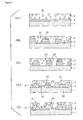
- Figures 1 (A)-(E) each show a sectional view of an embodiment of the inventive exhaust gas catalyst.
- Figure 1(A) shows an exhaust gas catalyst wherein a first layer 2 has been formed on a support 1 and a second layer 3 containing cavities 31 has been formed thereon.
- B) shows an exhaust gas catalyst wherein a first layer 2 containing through-channels 22 has been formed in corrugated fashion on a support 1, and a second layer 3 containing cavities 31 has been formed thereon.
- C shows an exhaust gas catalyst wherein a first layer 2 containing through-channels 22 has been formed in sea-island fashion on a support 1 and a second layer 3 containing cavities 31 has been formed thereon.
- FIG. D shows an exhaust gas catalyst wherein a first layer 2 containing cavities 21 and through-channels 22 has been formed in corrugated and sea-island fashion on a support 1 and a second layer 3 containing cavities 31 and through-channels 32 has been formed thereon.
- E shows an exhaust gas catalyst wherein a first layer 2 containing cavities 21 has been formed in corrugated fashion on a support 1 and a second layer 3 containing cavities 31 has been formed thereon. In the latter exhaust gas catalyst, the first layer 2 is in places incompletely covered by the second layer 3, as shown by 4 in Figure 1 (E).
- the first layer 2 and second layer 3 of the exhaust gas catalyst are mutually adjacent and contain cavities (21 or 31) or through-channels (22 or 32) as voids therein.
- the first layer 2 and second layer 3 may have the same or different mean porosities. Effective treatment of the exhaust is possible with such exhaust gas catalysts because the gas diffusivity of the exhaust gas is enhanced and the area of contact with exhaust gas is enlarged.
- At least one or both of the above first layer 2 and second layer 3 comprises catalyst components.
- the cavities or through-channels in the first layer 2 and second layer 3 are only examples of voids in the respective layers; the invention is not restricted to these geometries.
- the mean diameter of the voids in at least one of the plurality of layers is not less than 0.2 ⁇ m and not more than 500 ⁇ m, preferably with a lower limit of not less than 0.5 ⁇ m and upper limit of not more than 300 ⁇ m.
- mean diameter herein means four times the cross-sectional area of the voids, with reference to the maximum cross-sectional area, divided by the total perimeter on the cross-section.
- the mean porosity of the voids is not less than 5% and not more than 80%, preferably with an upper limit of not more than 60% and preferably with a lower limit of not less than 10%.
- the plurality of layers may be formed in any geometry, they are preferably formed in corrugated fashion. According to another preferred embodiment of the invention, at least one of the plurality of layers is formed on the support in sea-island fashion. These geometries may be formed physically when the plurality of layers is formed on the support, and are preferably formed by adjusting the geometry and amount of the forming agent as appropriate.
- the thickness of the individual layers in the plurality of layers is not less than 1 ⁇ m and not more than 300 ⁇ m, preferably with an upper limit of not more than 280 ⁇ m, preferably not more than 250 ⁇ m, and a lower limit of not less than 2 ⁇ m, preferably not less than 5 ⁇ m.
- the slurry is deposited on the support and calcined, forming layer one on the support.
- Another slurry is then deposited on the layer that has been formed and calcined to form another layer on the said layer one by the aforesaid procedure.
- the inventive exhaust gas catalyst is prepared by repetition of this procedure.
- the forming agent is preferably an agent that burns off when calcined or dried and imparts none of its chemical characteristics on the exhaust gas catalyst.
- the forming agent is preferably a pyrolysable or combustible material of spherical, cylindrical, etc, form. Specific examples thereof may be listed as bloating agents, surfactants, expanding synthetic resins, active carbon, graphite powder, pulp powder, organic fibre and plastic fibre. Specific examples of the bloating agents may be listed as La 2 (CO 3 ) 3 , Al 2 (CO 3 ) 3 and Ce 2 (CO) 3 , which preferably contain the same elements as the catalyst components.
- surfactants may be listed as anionic surfactants such as sulphonate and carboxylate surfactants, cationic surfactants such as amine surfactants, and amphoteric surfactants such as fatty acid ester surfactants.
- Specific examples of the expanding synthetic resins may be listed as polyurethane, polystyrene, polyethylene, polyester and acrylic synthetic resins.
- the voids may be formed by the bloating agent alone, or may be formed by apparatus capable of generating cells (e.g. microbubbles) of uniform size.
- the amount of forming agent added is not less than 5 wt% and not more than 80 wt% of the total weight of the components in each of the plurality of layers, preferably with an upper limit of not more than 70 wt%, preferably not more than 60 wt%, and a lower limit of not less than 5 wt%, preferably not less than 8 wt%.
- the powder of porous structure may be listed as aluminium oxide, cerium oxide, titanium oxide, zirconium oxide and crystalline zeolite.
- the catalyst components can be chosen as appropriate to the components of the exhaust gas, though according to a preferred embodiment of the invention, the catalyst components preferably comprise those of a three-way catalyst, oxidation catalyst, NOx occlusion-reduction catalyst or NOx selective reduction catalyst.
- the respective catalyst layers of a plurality of catalyst layers may comprise the same or different catalyst components.
- support may be listed as supports in pellet form (granular) consisting of alumina, or supports in monolithic form (honeycomb) consisting of cordierite ceramic or a metal such as stainless steel. Especially preferred are supports in monolithic form that have outstanding heat-resistance, thermal shock resistance and mechanical strength.
- the inventive exhaust gas catalyst may be constituted as follows, consistent with application to exhaust gas treatment.
- the invention provides a three-way catalyst, in which case at least one of the plurality of layers contains an active metal as three-way catalyst component, and if necessary a catalyst promoter.
- a noble metal may be cited as the active metal; platinum, palladium and rhodium may be listed as specific examples of the noble metal, which is preferably chosen from the group comprising platinum, palladium, rhodium and mixtures thereof.
- the amounts of active metal added are not less than 0.001 wt% and not more than 20 wt% of the total amount of three-way catalyst component, with an upper limit of preferably not more than 5 wt% and a lower limit of not less than 0.002 wt%, preferably not less than 0.005 wt%.
- catalyst promoter may be listed as promoters chosen from the group comprising aluminium oxide, cerium oxide, zirconium oxide, scandium oxide, yttrium oxide, lanthanum oxide, neodymium oxide, praseodymium oxide, zeolite and composite oxides thereof.
- the invention provides an oxidation catalyst, in which case at least one of the plurality of layers comprises an active metal as oxidation catalyst component, and if necessary a catalyst promoter.
- a noble metal may be cited as the active metal. Platinum, palladium and rhodium may be listed as specific examples of the noble metal, which is preferably chosen from the group comprising platinum, palladium, rhodium and mixtures thereof.
- the amount of active metal added is not less than 0.001 wt%, and not more than 30 wt%, of the total amount of the oxidation catalyst components, preferably with an upper limit of not more than 25 wt% and preferably with a lower limit of not less than 0.002 wt%.
- catalyst promoter may be listed as aluminium oxide, cerium oxide, zirconium oxide and zeolite.
- the invention provides an NOx occlusion type catalyst, in which case at least one of the plurality of layers comprises NOx occlusive agent, active metal, and if necessary a catalyst promoter as NOx occlusion type catalyst components.
- the NOx occlusive agent may be cited agents chosen from the group comprising alkali metals, alkaline earth metals, rare earth metals and mixtures thereof.
- alkali metals may be listed alkali metals chosen from the group comprising lithium, sodium, potassium, rubidium, caesium, francium and mixtures thereof.
- alkaline earth metals may be listed alkaline earth metals chosen from the group comprising beryllium, magnesium, calcium, strontium, barium and mixtures thereof.
- the rare earth metals may be listed scandium, yttrium, lanthanum, cerium, praseodymium, neodymium and mixtures thereof.
- the NOx occlusive agent can if necessary comprise a base metal, specific examples whereof may be listed as nickel, copper, manganese, iron, cobalt and zinc.
- the amount of NOx occlusive agent added is not less than 1 wt% and not more than 80 wt% of the total amount of the NOx occlusion-reduction catalyst components, preferably with an upper limit of not more than 75 wt%, preferably not more than 70 wt%, and a lower limit of not less than 2 wt%, preferably not less than 5 wt%.
- Noble metals and base metals may be listed as specific examples of the active metal.
- the noble metals may be cited metals chosen from the group comprising platinum, palladium, rhodium, ruthenium, iridium, osmium, gold , silver and mixtures thereof, whereof platinum, palladium, rhodium and mixtures thereof are preferred.
- the base metals may be listed nickel, copper, manganese, iron, cobalt, tungsten, molybdenum, zinc and mixtures thereof.
- the amount of active metal added is more than 0 wt% and not more than 50 wt% of the total amount of NOx occlusion-reduction catalyst components, preferably with an upper limit of not more than 45 wt%, preferably not more than 40 wt%.
- the catalyst promoter may be listed promoters chosen from the group comprising aluminium oxide, cerium oxide, zirconium oxide, titanium oxide, silica and their composite oxides.
- the amount of catalyst promoter added is more than 5 wt% and not more than 95 wt% with respect to the total amount of NOx occlusion reduction catalyst components, preferably with an upper limit of not more than 90 wt%, preferably not more than 60 wt%.
- the invention provides an NOx selective reduction catalyst, in which case at least one of the plurality of layers comprises active metal and catalyst promoter as NOx selective reduction catalyst.
- the active metal may be listed as metals chosen from the group comprising noble metals, transition metals, rare earth metals, mixtures thereof and oxides thereof; the active metal is preferably chosen from the group comprising platinum, gold, copper, vanadium, tungsten, titanium and oxides thereof.
- the amount of active metal added is not less than 0.001 wt% and not more than 20 wt% of the total amount of the NOx occlusion [sic] -reduction catalyst components, preferably with an upper limit of not more than 15 wt%, preferably not more than 10 wt%, and a lower limit of not less than 0.002 wt%, preferably not less than 0.005 wt%.
- catalyst promoters may be listed promoters chosen from the group comprising aluminium oxide, cerium oxide, zirconium oxide, titanium oxide, silica, zeolite and their composite oxides.
- the amount of catalyst promoter added is more than 1 wt% and not more than 50 wt% of the total amount of the NOx selective reduction catalyst components, preferably with an upper limit of not more than 45 wt%, preferably not more than 40 wt%.
- NOx selective reduction catalysts utilise a reducing agent for treating the nitrogen oxides in exhaust gas.
- the reducing agent may be listed as ammonia or amines, urea or its derivatives, hydrazine or its derivatives, triazine or its derivatives, hydrocarbons, or organic compounds containing oxygen atoms.
- Specific examples of the amines are amines of 1-5 carbon atoms, preferably methylamine. Guanidine and biuret are preferably listed as specific examples of the urea derivatives.
- Cyanuric acid is preferably listed as a specific example of the hydrazine derivatives.
- the hydrocarbons are gas oil, kerosene or C 3 -C 8 paraffins.
- the organic compounds containing oxygen atoms are alcohols (preferably alcohols of 1-5 carbon atoms, more preferably methanol and ethanol), ketones, ethers, organic carboxylic acids, fatty acids and esters.
- the invention provides exhaust gas treatment apparatus equipped with the inventive exhaust gas catalyst.
- the scope of the inventive exhaust gas treatment apparatus will be explained with the aid of Figure 2.
- Figure 2 is an outline diagram of exhaust gas treatment apparatus equipped with the inventive exhaust gas catalyst.
- the inventive exhaust gas treatment apparatus 50 consists of an assembly provided with an exhaust gas inlet 52 and exhaust gas exit 53, wherein is provided the inventive exhaust gas catalyst 51.
- the exhaust gas enters at the inlet 52, at least one of the hydrocarbon, carbon monoxide and nitrogen oxide components of the exhaust gas is treated in the inventive exhaust gas catalyst 51, and the treated exhaust gas is discharged via the exit 53.
- the exhaust gas catalyst 51 in Figure 2 is a three-way catalyst of the invention, the hydrocarbon, the carbon monoxide and the nitrogen oxides in the exhaust gas are treated with the exhaust gas catalyst (three-way catalyst) and converted to water, carbon dioxide and nitrogen. If, according to another preferred embodiment of the invention, the exhaust gas catalyst 51 in Figure 2 is an oxidation catalyst of the invention, the hydrocarbon and carbon monoxide in the exhaust gas are treated with the exhaust gas catalyst (oxidation catalyst) and converted to water and carbon dioxide.
- the exhaust gas catalyst 51 in Figure 2 is an NOx occlusion-reduction catalyst of the invention
- the nitrogen oxides in the exhaust gas are treated with the exhaust gas catalyst (NOx occlusion-reduction catalyst) and converted to water and nitrogen.
- the exhaust gas catalyst 51 in Figure 2 is an NOx selective reduction catalyst of the invention
- the nitrogen oxides in the exhaust gas are treated by the exhaust gas catalyst (NOx selective reduction catalyst) together with reducing agent and converted to water and nitrogen; wherein the reducing agent is admitted from a reducing agent inlet located in front of the exhaust gas catalyst 51.
- the inventive exhaust gas catalyst is used to clean up exhaust gas.
- the inventive exhaust gas catalyst and the apparatus using it are used in the exhaust systems of internal combustion engines, particularly spark-ignition engines (for example petrol engines) and compression-ignition engines (for example diesel engines).
- the said engines may be engines burning fuel with adjustment of the air-fuel ratio, whereof preferred specific examples may be listed as lean burn engines, direct injection engines, and preferably a combination of these (i.e. direct injection lean burn engines).
- a direct injection engine employs a fuel delivery system capable of delivering a higher compression ratio, enhanced combustion efficiency and lower exhaust emission. Combined with a lean burn engine, therefore, it is capable of further enhancing combustion efficiency and reducing exhaust emission.
- the inventive exhaust gas catalyst is utilised in the exhaust gas systems of the internal combustion engines mounted in conveyances, machines, etc.
- conveyances and machines may be listed as: means of transport, such as cars, buses, trucks, dumper cars, diesel railcars, motorbikes, motorised cycles, ships, tankers, motor boats and aircraft; agriculture and forestry machines such as cultivators, tractors, combine harvesters, chain saws and lumber conveyors; fisheries machines such as fishing vessels; civil engineering machines such as tank lorries, cranes, compressors and diggers; and power generators.
- the inventive exhaust gas catalyst can be installed as a starter catalyst, underfloor converter or manifold converter.
- ⁇ -Al 2 O 3 powder 25 parts by weight, water 60 parts by weight and platinum nitrate solution were mixed and an acrylic resin [a resin of mean diameter ca. 30 ⁇ m to ca. 150 ⁇ m (on average ca. 60 ⁇ m) was used] was further mixed therewith as forming agent to constitute 10 wt% of the total.
- a slurry wherein the forming agent was uniformly dispersed was obtained by agitating for 30 min in an air atmosphere with a high speed mixer (Silverson Machines Inc.).
- a cordierite honeycomb substrate (volume 1000 cc, 600 cells/in 2 : NGK Insulators Ltd.) was prepared, dipped in the aforesaid slurry, and withdrawn; after excess slurry had been blown off, the support was calcined for 1 hour at 500°C in air to lay down a first layer.
- ⁇ -Al 2 O 3 powder 5 parts by weight, water 20 parts by weight and rhodium nitrate solution were mixed and an acrylic resin [a resin of mean diameter ca. 0.5 ⁇ m to ca. 100 ⁇ m (on average ca.
- the honeycomb substrate whereon the first layer had been formed was then dipped in the aforesaid slurry and withdrawn; after excess slurry had been blown off, the support was calcined for 1 hour at 500°C in air to lay down a second layer, affording an exhaust gas catalyst (three-way catalyst).
- the exhaust gas catalyst had a catalyst loading per litre of honeycomb substrate of Pt (platinum) 0.54 g and Rh (rhodium) 0.07 g.
- An exhaust gas catalyst was obtained as in Example 1 except that the second layer was formed without addition of forming agent.
- An exhaust gas catalyst was obtained as in Example 1 except that the first layer was formed without addition of forming agent.
- An exhaust gas catalyst was obtained as in Example 1 except that the first layer and second layer were formed without addition of forming agent.
- Specimens cut to diameter 25.4 mm, length 30 mm, from the catalysts of Examples 1-3 and Comparative Example 1 were respectively mounted in a test unit having an exhaust gas inlet and exit (Horiba Seisakusho Ltd.). Heat treatment was carried out for 20 min while the gas of rich composition and gas of lean composition shown in Table 1 were alternately admitted from the inlet of the test unit every 3 min at a gas temperature of 900°C. The gas of rich composition and gas of lean composition shown in Table 2 were then each admitted from the inlet of the unit at 1 Hz, whereupon the percentage NOx clean-up was measured. Measurements were made at gas temperatures of 280°C and 300°C. The 5 minute mean clean-up (%) at each temperature is shown in Table 3. In Tables 1 and 2, (%) signifies volume percent.
- ⁇ -Al 2 O 3 powder 10 parts by weight, 15 parts by weight of a composite oxide of cerium oxide and zirconium oxide, water 77 parts by weight and platinum nitrate solution were mixed, and an acrylic resin [a resin of mean diameter ca. 30 ⁇ m to ca. 150 ⁇ m (on average ca. 60 ⁇ m) was used] was further mixed therewith as forming agent to constitute 14 wt% of the total.
- a slurry wherein the forming agent was uniformly dispersed was obtained by agitating for 30 min in an air atmosphere with a high speed mixer (Silverson Machines Inc.).
- a cordierite honeycomb substrate (volume 1000 cc, 600 cells/in 2 : NGK Insulators Ltd.) was prepared, dipped in the aforesaid slurry, and withdrawn; after excess slurry had been blown off, the support was calcined in air for 1 hour at 500°C to lay down a first layer.
- ⁇ -Al 2 O 3 powder 5 parts by weight, 5 parts by weight of a composite oxide of cerium oxide and zirconium oxide, water 76 parts by weight and rhodium nitrate solution were mixed and an acrylic resin [a resin of mean diameter ca. 4 ⁇ m to ca. 7 ⁇ m (on average ca.
- the honeycomb substrate whereon the first layer had been formed was then dipped in the slurry and withdrawn; after excess slurry had been blown off, the support was calcined for 1 hour at 500°C in air to lay down a second layer, thus affording an exhaust gas catalyst (three-way catalyst).
- the exhaust gas catalyst had a catalyst loading per litre of honeycomb substrate of Pt (platinum) 0.75 g and Rh (rhodium) 0.075 g.
- An exhaust gas catalyst was obtained as in Example 4 except that the first layer and second layer were formed without addition of forming agent.
- the respective catalysts were then accommodated in cylinders of diameter 15 cm, length 40 cm, mounted in a petrol engine vehicle with a displacement volume of 2200 cc, regular grade petrol fuel was burned and performance was evaluated in FTP mode (a transient mode exhaust gas test).
- An evaluation unit of tradename "Mexa 9000" Horiba Seisakusho Ltd.
- a slurry wherein the forming agent was uniformly dispersed was obtained by agitating for 30 min in an air atmosphere with a high speed mixer (Silverson Machines Inc.).
- a cordierite honeycomb substrate (volume 635 cc, 600 cells/in 2 : NGK Insulators Ltd.) was prepared, dipped in the aforesaid slurry, and withdrawn; after excess slurry had been blown off, the support was calcined in air for 1 hour at 500°C to lay down a first layer.
- ⁇ -Al 2 O 3 powder 6 parts by weight, 6 parts by weight of a composite oxide of cerium oxide and zirconium oxide, water 80 parts by weight and rhodium nitrate solution were mixed and an acrylic resin [a resin of mean diameter ca. 4 ⁇ m to ca. 7 ⁇ m (on average ca.
- the honeycomb substrate whereon the first layer had been formed was then dipped in the slurry and withdrawn; after excess slurry had been blown off, the support was calcined for 1 hour at 500°C in air to lay down a second layer, thus affording an exhaust gas catalyst (three-way catalyst).
- the exhaust gas catalyst had a catalyst loading of Pd (palladium) 0.53 g and Rh (rhodium) 0.11 g per litre of honeycomb substrate.
- An exhaust gas catalyst was obtained as in Example 5 except that the first layer and second layer were formed without the addition of forming agent.
- the respective catalysts were then re-housed in canisters, mounted in a petrol engine vehicle with a displacement volume of 2000 cc, regular grade petrol fuel was burned and performance was evaluated in 11P mode (vehicle exhaust mode).
- An evaluation unit of tradename "Mexa 9000" (Horiba Seisakusho Ltd.) was used.
Landscapes
- Chemical & Material Sciences (AREA)
- Engineering & Computer Science (AREA)
- Chemical Kinetics & Catalysis (AREA)
- Materials Engineering (AREA)
- Organic Chemistry (AREA)
- Combustion & Propulsion (AREA)
- Health & Medical Sciences (AREA)
- Mechanical Engineering (AREA)
- Toxicology (AREA)
- General Engineering & Computer Science (AREA)
- Biomedical Technology (AREA)
- Environmental & Geological Engineering (AREA)
- Analytical Chemistry (AREA)
- General Chemical & Material Sciences (AREA)
- Oil, Petroleum & Natural Gas (AREA)
- Catalysts (AREA)
- Exhaust Gas Treatment By Means Of Catalyst (AREA)
- Exhaust Gas After Treatment (AREA)
Abstract
Description
- The invention relates to an exhaust gas catalyst wherein a plurality of layers has been formed on a support.
- The following may be listed as specific examples of exhaust gas catalysts for internal combustion engines and automotive engines in particular: oxidation catalysts for simultaneously treating hydrocarbon (HC) and carbon monoxide (CO) in exhaust gas; three-way catalysts for simultaneously treating the hydrocarbon, carbon monoxide and nitrogen oxides (NOx) in exhaust gas; NOx occlusion-reduction catalysts, wherein NOx is occluded from the exhaust gas at lean air-fuel ratio, the air-fuel ratio is switched to the theoretical air-fuel ratio or a rich air-fuel ratio before the occluded NOx reaches saturation, and the NOx is thereby reduced; and NOx selective reduction catalysts that reduce the NOx in the exhaust gas by means of a reducing agent.
- Oxidation catalysts, three-way catalysts, NOx occlusion-reduction catalysts and NOx selective reduction catalysts are manufactured by making the catalyst components into a slurry, soaking onto a support such as a ceramic support of honeycomb geometry and calcining.
- In nearly all existing exhaust gas catalysts, however, the catalyst components are formed uniformly on the support; gas diffusion in the exhaust gas is therefore slow when the exhaust gas flows into the exhaust gas catalyst, and as a result the exhaust gas is often found to be incompletely treated.
- In view of this,
Japan Patent Kokai No. 2002-191988 Japan Patent Kokai No. 2002-253968 - Patent reference 1:
Japan Patent Kokai No. 2002-191988 Japan Patent Kokai No. 2002-253968 - In devising the invention, the inventors discovered the constitution of an exhaust gas catalyst that improved the treatment of exhaust gas. In particular, they found that the treatment of exhaust gas could be improved by means of a catalyst formed from a plurality of layers wherein at least one of the plurality of layers contained voids of specified minor axis and diameter and comprised catalyst components. The invention is accordingly based on these findings. The invention aims thereby to provide an exhaust gas catalyst that raises the gas diffusibility of the exhaust gas, enabling treatment of the exhaust gas to be improved.
- Accordingly, the exhaust gas catalyst claimed for the invention is an exhaust gas catalyst wherein at least are provided a support and a plurality of layers formed on the said support,
at least one of the aforesaid plurality of layers containing voids therewithin,
and at least one of the aforesaid plurality of layers comprising catalyst components. -
- Figure 1 Figures 1(A)-(E) are outline drawings of the inventive exhaust gas catalyst.
- Figure 2 Figure 2 is an outline drawing of the inventive apparatus for treating exhaust gas.
- The inventive exhaust gas catalyst is constituted as a catalyst wherein at least one of a plurality of layers contains voids therewithin. In the invention, at least one of the plurality of layers comprises catalyst components. "Void" herein signifies that a space exists in the layer; specific examples thereof may be listed as a cavity, a pore, or a narrow elongated pore in tunnel (cylindrical and/or prismatic) form.
- According to a preferred embodiment of the invention, it is preferred that at least one of the aforesaid plurality of layers comprising the aforesaid catalyst components in the inventive exhaust gas catalyst contains voids therewithin. According to a more preferred embodiment, it is preferred that the mean diameter of the aforesaid voids in the inventive exhaust gas catalyst is not less than 0.2 µm and not more than 500 µm.
- Embodiments of the inventive exhaust gas catalyst will be explained with Figure 1. Figures 1 (A)-(E) each show a sectional view of an embodiment of the inventive exhaust gas catalyst. Figure 1(A) shows an exhaust gas catalyst wherein a
first layer 2 has been formed on asupport 1 and asecond layer 3 containingcavities 31 has been formed thereon. (B) shows an exhaust gas catalyst wherein afirst layer 2 containing through-channels 22 has been formed in corrugated fashion on asupport 1, and asecond layer 3 containingcavities 31 has been formed thereon. (C) shows an exhaust gas catalyst wherein afirst layer 2 containing through-channels 22 has been formed in sea-island fashion on asupport 1 and asecond layer 3 containingcavities 31 has been formed thereon. (D) shows an exhaust gas catalyst wherein afirst layer 2 containingcavities 21 and through-channels 22 has been formed in corrugated and sea-island fashion on asupport 1 and asecond layer 3 containingcavities 31 and through-channels 32 has been formed thereon. (E) shows an exhaust gas catalyst wherein afirst layer 2 containingcavities 21 has been formed in corrugated fashion on asupport 1 and asecond layer 3 containingcavities 31 has been formed thereon. In the latter exhaust gas catalyst, thefirst layer 2 is in places incompletely covered by thesecond layer 3, as shown by 4 in Figure 1 (E).
As shown in Figures 1(A)-(E), thefirst layer 2 andsecond layer 3 of the exhaust gas catalyst are mutually adjacent and contain cavities (21 or 31) or through-channels (22 or 32) as voids therein. Thefirst layer 2 andsecond layer 3 may have the same or different mean porosities. Effective treatment of the exhaust is possible with such exhaust gas catalysts because the gas diffusivity of the exhaust gas is enhanced and the area of contact with exhaust gas is enlarged.
At least one or both of the abovefirst layer 2 andsecond layer 3 comprises catalyst components. The cavities or through-channels in thefirst layer 2 andsecond layer 3 are only examples of voids in the respective layers; the invention is not restricted to these geometries. - According to the preferred embodiment of the invention, the mean diameter of the voids in at least one of the plurality of layers is not less than 0.2 µm and not more than 500 µm, preferably with a lower limit of not less than 0.5 µm and upper limit of not more than 300 µm. "Mean diameter" herein means four times the cross-sectional area of the voids, with reference to the maximum cross-sectional area, divided by the total perimeter on the cross-section. Where voids are present in at least one of the plurality of layers in the invention, the mean porosity of the voids is not less than 5% and not more than 80%, preferably with an upper limit of not more than 60% and preferably with a lower limit of not less than 10%.
- According to a preferred embodiment of the invention, although the plurality of layers may be formed in any geometry, they are preferably formed in corrugated fashion. According to another preferred embodiment of the invention, at least one of the plurality of layers is formed on the support in sea-island fashion. These geometries may be formed physically when the plurality of layers is formed on the support, and are preferably formed by adjusting the geometry and amount of the forming agent as appropriate.
- The thickness of the individual layers in the plurality of layers is not less than 1 µm and not more than 300 µm, preferably with an upper limit of not more than 280 µm, preferably not more than 250 µm, and a lower limit of not less than 2 µm, preferably not less than 5 µm.
- The following may be listed as a specific example of means of forming the plurality of layers on the support. A powder of porous structure, if necessary the catalyst components (if a catalyst layer is to be formed), and the forming agent, are added to a solvent (for instance water) and agitated to prepare a slurry. The slurry is deposited on the support and calcined, forming layer one on the support. Another slurry is then deposited on the layer that has been formed and calcined to form another layer on the said layer one by the aforesaid procedure. The inventive exhaust gas catalyst is prepared by repetition of this procedure.
- The forming agent is preferably an agent that burns off when calcined or dried and imparts none of its chemical characteristics on the exhaust gas catalyst. The forming agent is preferably a pyrolysable or combustible material of spherical, cylindrical, etc, form. Specific examples thereof may be listed as bloating agents, surfactants, expanding synthetic resins, active carbon, graphite powder, pulp powder, organic fibre and plastic fibre. Specific examples of the bloating agents may be listed as La2(CO3)3, Al2(CO3)3 and Ce2(CO)3, which preferably contain the same elements as the catalyst components. Specific examples of the surfactants may be listed as anionic surfactants such as sulphonate and carboxylate surfactants, cationic surfactants such as amine surfactants, and amphoteric surfactants such as fatty acid ester surfactants. Specific examples of the expanding synthetic resins may be listed as polyurethane, polystyrene, polyethylene, polyester and acrylic synthetic resins. The voids may be formed by the bloating agent alone, or may be formed by apparatus capable of generating cells (e.g. microbubbles) of uniform size.
- The amount of forming agent added is not less than 5 wt% and not more than 80 wt% of the total weight of the components in each of the plurality of layers, preferably with an upper limit of not more than 70 wt%, preferably not more than 60 wt%, and a lower limit of not less than 5 wt%, preferably not less than 8 wt%.
- Specific examples of the powder of porous structure may be listed as aluminium oxide, cerium oxide, titanium oxide, zirconium oxide and crystalline zeolite. When at least one of the plurality of layers comprises catalyst components, the catalyst components can be chosen as appropriate to the components of the exhaust gas, though according to a preferred embodiment of the invention, the catalyst components preferably comprise those of a three-way catalyst, oxidation catalyst, NOx occlusion-reduction catalyst or NOx selective reduction catalyst. The respective catalyst layers of a plurality of catalyst layers may comprise the same or different catalyst components.
- Specific examples of the support may be listed as supports in pellet form (granular) consisting of alumina, or supports in monolithic form (honeycomb) consisting of cordierite ceramic or a metal such as stainless steel. Especially preferred are supports in monolithic form that have outstanding heat-resistance, thermal shock resistance and mechanical strength.
- The inventive exhaust gas catalyst may be constituted as follows, consistent with application to exhaust gas treatment.
- According to another embodiment the invention provides a three-way catalyst, in which case at least one of the plurality of layers contains an active metal as three-way catalyst component, and if necessary a catalyst promoter.
- A noble metal may be cited as the active metal; platinum, palladium and rhodium may be listed as specific examples of the noble metal, which is preferably chosen from the group comprising platinum, palladium, rhodium and mixtures thereof. The amounts of active metal added are not less than 0.001 wt% and not more than 20 wt% of the total amount of three-way catalyst component, with an upper limit of preferably not more than 5 wt% and a lower limit of not less than 0.002 wt%, preferably not less than 0.005 wt%.
- Specific examples of the catalyst promoter may be listed as promoters chosen from the group comprising aluminium oxide, cerium oxide, zirconium oxide, scandium oxide, yttrium oxide, lanthanum oxide, neodymium oxide, praseodymium oxide, zeolite and composite oxides thereof.
- According to another embodiment the invention provides an oxidation catalyst, in which case at least one of the plurality of layers comprises an active metal as oxidation catalyst component, and if necessary a catalyst promoter.
- A noble metal may be cited as the active metal. Platinum, palladium and rhodium may be listed as specific examples of the noble metal, which is preferably chosen from the group comprising platinum, palladium, rhodium and mixtures thereof.
The amount of active metal added is not less than 0.001 wt%, and not more than 30 wt%, of the total amount of the oxidation catalyst components, preferably with an upper limit of not more than 25 wt% and preferably with a lower limit of not less than 0.002 wt%. - Specific examples of the catalyst promoter may be listed as aluminium oxide, cerium oxide, zirconium oxide and zeolite.
- According to another embodiment the invention provides an NOx occlusion type catalyst, in which case at least one of the plurality of layers comprises NOx occlusive agent, active metal, and if necessary a catalyst promoter as NOx occlusion type catalyst components.
- As specific examples of the NOx occlusive agent may be cited agents chosen from the group comprising alkali metals, alkaline earth metals, rare earth metals and mixtures thereof.
As specific examples of alkali metals may be listed alkali metals chosen from the group comprising lithium, sodium, potassium, rubidium, caesium, francium and mixtures thereof.
As specific examples of alkaline earth metals may be listed alkaline earth metals chosen from the group comprising beryllium, magnesium, calcium, strontium, barium and mixtures thereof.
As specific examples of the rare earth metals may be listed scandium, yttrium, lanthanum, cerium, praseodymium, neodymium and mixtures thereof.
The NOx occlusive agent can if necessary comprise a base metal, specific examples whereof may be listed as nickel, copper, manganese, iron, cobalt and zinc.
The amount of NOx occlusive agent added is not less than 1 wt% and not more than 80 wt% of the total amount of the NOx occlusion-reduction catalyst components, preferably with an upper limit of not more than 75 wt%, preferably not more than 70 wt%, and a lower limit of not less than 2 wt%, preferably not less than 5 wt%. - Noble metals and base metals may be listed as specific examples of the active metal. As specific examples of the noble metals may be cited metals chosen from the group comprising platinum, palladium, rhodium, ruthenium, iridium, osmium, gold , silver and mixtures thereof, whereof platinum, palladium, rhodium and mixtures thereof are preferred.
As specific examples of the base metals may be listed nickel, copper, manganese, iron, cobalt, tungsten, molybdenum, zinc and mixtures thereof.
The amount of active metal added is more than 0 wt% and not more than 50 wt% of the total amount of NOx occlusion-reduction catalyst components, preferably with an upper limit of not more than 45 wt%, preferably not more than 40 wt%. - As specific examples of the catalyst promoter may be listed promoters chosen from the group comprising aluminium oxide, cerium oxide, zirconium oxide, titanium oxide, silica and their composite oxides. The amount of catalyst promoter added is more than 5 wt% and not more than 95 wt% with respect to the total amount of NOx occlusion reduction catalyst components, preferably with an upper limit of not more than 90 wt%, preferably not more than 60 wt%.
- According to another embodiment, the invention provides an NOx selective reduction catalyst, in which case at least one of the plurality of layers comprises active metal and catalyst promoter as NOx selective reduction catalyst.
- Specific examples of the active metal may be listed as metals chosen from the group comprising noble metals, transition metals, rare earth metals, mixtures thereof and oxides thereof; the active metal is preferably chosen from the group comprising platinum, gold, copper, vanadium, tungsten, titanium and oxides thereof.
The amount of active metal added is not less than 0.001 wt% and not more than 20 wt% of the total amount of the NOx occlusion[sic]-reduction catalyst components, preferably with an upper limit of not more than 15 wt%, preferably not more than 10 wt%, and a lower limit of not less than 0.002 wt%, preferably not less than 0.005 wt%. - As catalyst promoters may be listed promoters chosen from the group comprising aluminium oxide, cerium oxide, zirconium oxide, titanium oxide, silica, zeolite and their composite oxides. The amount of catalyst promoter added is more than 1 wt% and not more than 50 wt% of the total amount of the NOx selective reduction catalyst components, preferably with an upper limit of not more than 45 wt%, preferably not more than 40 wt%.
- NOx selective reduction catalysts utilise a reducing agent for treating the nitrogen oxides in exhaust gas. Specific examples of the reducing agent may be listed as ammonia or amines, urea or its derivatives, hydrazine or its derivatives, triazine or its derivatives, hydrocarbons, or organic compounds containing oxygen atoms.
Specific examples of the amines are amines of 1-5 carbon atoms, preferably methylamine. Guanidine and biuret are preferably listed as specific examples of the urea derivatives. Cyanuric acid is preferably listed as a specific example of the hydrazine derivatives. Specific examples of the hydrocarbons are gas oil, kerosene or C3-C8 paraffins. Specific examples of the organic compounds containing oxygen atoms are alcohols (preferably alcohols of 1-5 carbon atoms, more preferably methanol and ethanol), ketones, ethers, organic carboxylic acids, fatty acids and esters. - According to another embodiment, the invention provides exhaust gas treatment apparatus equipped with the inventive exhaust gas catalyst. The scope of the inventive exhaust gas treatment apparatus will be explained with the aid of Figure 2. Figure 2 is an outline diagram of exhaust gas treatment apparatus equipped with the inventive exhaust gas catalyst. The inventive exhaust
gas treatment apparatus 50 consists of an assembly provided with anexhaust gas inlet 52 andexhaust gas exit 53, wherein is provided the inventiveexhaust gas catalyst 51. The exhaust gas enters at theinlet 52, at least one of the hydrocarbon, carbon monoxide and nitrogen oxide components of the exhaust gas is treated in the inventiveexhaust gas catalyst 51, and the treated exhaust gas is discharged via theexit 53. - If, according to a preferred embodiment of the invention, the
exhaust gas catalyst 51 in Figure 2 is a three-way catalyst of the invention, the hydrocarbon, the carbon monoxide and the nitrogen oxides in the exhaust gas are treated with the exhaust gas catalyst (three-way catalyst) and converted to water, carbon dioxide and nitrogen. If, according to another preferred embodiment of the invention, theexhaust gas catalyst 51 in Figure 2 is an oxidation catalyst of the invention, the hydrocarbon and carbon monoxide in the exhaust gas are treated with the exhaust gas catalyst (oxidation catalyst) and converted to water and carbon dioxide. If, according to another preferred embodiment of the invention, theexhaust gas catalyst 51 in Figure 2 is an NOx occlusion-reduction catalyst of the invention, the nitrogen oxides in the exhaust gas are treated with the exhaust gas catalyst (NOx occlusion-reduction catalyst) and converted to water and nitrogen. If theexhaust gas catalyst 51 in Figure 2 is an NOx selective reduction catalyst of the invention, the nitrogen oxides in the exhaust gas are treated by the exhaust gas catalyst (NOx selective reduction catalyst) together with reducing agent and converted to water and nitrogen; wherein the reducing agent is admitted from a reducing agent inlet located in front of theexhaust gas catalyst 51. - The inventive exhaust gas catalyst is used to clean up exhaust gas. The inventive exhaust gas catalyst and the apparatus using it are used in the exhaust systems of internal combustion engines, particularly spark-ignition engines (for example petrol engines) and compression-ignition engines (for example diesel engines). The said engines may be engines burning fuel with adjustment of the air-fuel ratio, whereof preferred specific examples may be listed as lean burn engines, direct injection engines, and preferably a combination of these (i.e. direct injection lean burn engines). A direct injection engine employs a fuel delivery system capable of delivering a higher compression ratio, enhanced combustion efficiency and lower exhaust emission. Combined with a lean burn engine, therefore, it is capable of further enhancing combustion efficiency and reducing exhaust emission.
- The inventive exhaust gas catalyst is utilised in the exhaust gas systems of the internal combustion engines mounted in conveyances, machines, etc. Specific examples of the conveyances and machines may be listed as: means of transport, such as cars, buses, trucks, dumper cars, diesel railcars, motorbikes, motorised cycles, ships, tankers, motor boats and aircraft; agriculture and forestry machines such as cultivators, tractors, combine harvesters, chain saws and lumber conveyors; fisheries machines such as fishing vessels; civil engineering machines such as tank lorries, cranes, compressors and diggers; and power generators. In the case of vehicle exhaust systems, for example, the inventive exhaust gas catalyst can be installed as a starter catalyst, underfloor converter or manifold converter.
- The content of the invention will be described in detail with working examples. However, the content of the invention is not to be construed as limited by the said examples.
- γ-Al2O3 powder 25 parts by weight, water 60 parts by weight and platinum nitrate solution were mixed and an acrylic resin [a resin of mean diameter ca. 30 µm to ca. 150 µm (on average ca. 60 µm) was used] was further mixed therewith as forming agent to constitute 10 wt% of the total. A slurry wherein the forming agent was uniformly dispersed was obtained by agitating for 30 min in an air atmosphere with a high speed mixer (Silverson Machines Inc.). A cordierite honeycomb substrate (volume 1000 cc, 600 cells/in2: NGK Insulators Ltd.) was prepared, dipped in the aforesaid slurry, and withdrawn; after excess slurry had been blown off, the support was calcined for 1 hour at 500°C in air to lay down a first layer.
γ-Al2O3 powder 5 parts by weight, water 20 parts by weight and rhodium nitrate solution were mixed and an acrylic resin [a resin of mean diameter ca. 0.5 µm to ca. 100 µm (on average ca. 20 µm) was used] was further mixed therewith as forming agent to constitute 20 wt% of the total; agitation for 30 min in an air atmosphere with the aforesaid high speed mixer gave a slurry wherein the forming agent was uniformly dispersed. The honeycomb substrate whereon the first layer had been formed was then dipped in the aforesaid slurry and withdrawn; after excess slurry had been blown off, the support was calcined for 1 hour at 500°C in air to lay down a second layer, affording an exhaust gas catalyst (three-way catalyst).
The exhaust gas catalyst had a catalyst loading per litre of honeycomb substrate of Pt (platinum) 0.54 g and Rh (rhodium) 0.07 g. - An exhaust gas catalyst was obtained as in Example 1 except that the second layer was formed without addition of forming agent.
- An exhaust gas catalyst was obtained as in Example 1 except that the first layer was formed without addition of forming agent.
- An exhaust gas catalyst was obtained as in Example 1 except that the first layer and second layer were formed without addition of forming agent.
- Specimens cut to diameter 25.4 mm, length 30 mm, from the catalysts of Examples 1-3 and Comparative Example 1 were respectively mounted in a test unit having an exhaust gas inlet and exit (Horiba Seisakusho Ltd.). Heat treatment was carried out for 20 min while the gas of rich composition and gas of lean composition shown in Table 1 were alternately admitted from the inlet of the test unit every 3 min at a gas temperature of 900°C. The gas of rich composition and gas of lean composition shown in Table 2 were then each admitted from the inlet of the unit at 1 Hz, whereupon the percentage NOx clean-up was measured. Measurements were made at gas temperatures of 280°C and 300°C. The 5 minute mean clean-up (%) at each temperature is shown in Table 3. In Tables 1 and 2, (%) signifies volume percent.
-
Table 1 CO H2 O2 H2O N2 Rich 3% 3% 10% balance Lean 3% 10% balance -
Table 2 C3H6 (ppm) O2 (%) NO (ppm) CO (%) H2 (%) CO2 (%) H2O (%) N2 Rich 400 0.50 500 2.11 0.70 14.0 10% balance Lean 400 1.54 500 0.50 0.17 14.0 10% balance -
Table 3 NOx clean-up (%) 280°C 300°C Working example 1 70.9 66.9 Working example 2 70.0 66.0 Working example 3 69.3 67.3 Comparative example 1 68.2 64.1 - γ-Al2O3 powder 10 parts by weight, 15 parts by weight of a composite oxide of cerium oxide and zirconium oxide, water 77 parts by weight and platinum nitrate solution were mixed, and an acrylic resin [a resin of mean diameter ca. 30 µm to ca. 150 µm (on average ca. 60 µm) was used] was further mixed therewith as forming agent to constitute 14 wt% of the total. A slurry wherein the forming agent was uniformly dispersed was obtained by agitating for 30 min in an air atmosphere with a high speed mixer (Silverson Machines Inc.). A cordierite honeycomb substrate (volume 1000 cc, 600 cells/in2: NGK Insulators Ltd.) was prepared, dipped in the aforesaid slurry, and withdrawn; after excess slurry had been blown off, the support was calcined in air for 1 hour at 500°C to lay down a first layer.
γ-Al2O3 powder 5 parts by weight, 5 parts by weight of a composite oxide of cerium oxide and zirconium oxide, water 76 parts by weight and rhodium nitrate solution were mixed and an acrylic resin [a resin of mean diameter ca. 4 µm to ca. 7 µm (on average ca. 5 µm) was used] was further mixed therewith as forming agent to constitute 8 wt% of the total; agitation for 30 min in an air atmosphere with the aforesaid high speed mixer gave a slurry wherein the forming agent was uniformly dispersed. The honeycomb substrate whereon the first layer had been formed was then dipped in the slurry and withdrawn; after excess slurry had been blown off, the support was calcined for 1 hour at 500°C in air to lay down a second layer, thus affording an exhaust gas catalyst (three-way catalyst).
The exhaust gas catalyst had a catalyst loading per litre of honeycomb substrate of Pt (platinum) 0.75 g and Rh (rhodium) 0.075 g. - An exhaust gas catalyst was obtained as in Example 4 except that the first layer and second layer were formed without addition of forming agent.
- The catalysts for exhaust gas clean-up obtained in Example 4 and Comparative Example 2 were respectively accommodated in a catalyst canister, installed in the exhaust system of the 4000 cc displacement volume petrol engine, and left in place for 50 hours at a temperature in the catalyst bed of 900°C while regular grade petrol fuel was burned under conditions of A/F variation = 14.5 (steady-state).
The respective catalysts were then accommodated in cylinders of diameter 15 cm, length 40 cm, mounted in a petrol engine vehicle with a displacement volume of 2200 cc, regular grade petrol fuel was burned and performance was evaluated in FTP mode (a transient mode exhaust gas test). An evaluation unit of tradename "Mexa 9000" (Horiba Seisakusho Ltd.) was used. The evaluation results are recorded in Table 4 below, lower figures denoting a higher exhaust gas cleaning capacity.Table 4 Example/ evaluation test 2THC CO NOx Example 4 0.058 0.28 0.106 Comparative Example 2 0.058 0.26 0.120 - γ-Al2O3 powder 16 parts by weight, 8 parts by weight of a composite oxide of cerium oxide and zirconium oxide, water 65 parts by weight and palladium nitrate solution were mixed, and an acrylic resin [a resin of mean diameter ca. 4 µm to ca. 7 µm (on average ca. 5 µm) was used] was further mixed therewith as forming agent to constitute 8 wt% of the total. A slurry wherein the forming agent was uniformly dispersed was obtained by agitating for 30 min in an air atmosphere with a high speed mixer (Silverson Machines Inc.). A cordierite honeycomb substrate (volume 635 cc, 600 cells/in2: NGK Insulators Ltd.) was prepared, dipped in the aforesaid slurry, and withdrawn; after excess slurry had been blown off, the support was calcined in air for 1 hour at 500°C to lay down a first layer.
γ-Al2O3 powder 6 parts by weight, 6 parts by weight of a composite oxide of cerium oxide and zirconium oxide, water 80 parts by weight and rhodium nitrate solution were mixed and an acrylic resin [a resin of mean diameter ca. 4 µm to ca. 7 µm (on average ca. 5 µm) was used] was further mixed therewith as forming agent to constitute 6 wt% of the total; agitation for 30 min in an air atmosphere with the aforesaid high speed mixer gave a slurry wherein the forming agent was uniformly dispersed. The honeycomb substrate whereon the first layer had been formed was then dipped in the slurry and withdrawn; after excess slurry had been blown off, the support was calcined for 1 hour at 500°C in air to lay down a second layer, thus affording an exhaust gas catalyst (three-way catalyst).
The exhaust gas catalyst had a catalyst loading of Pd (palladium) 0.53 g and Rh (rhodium) 0.11 g per litre of honeycomb substrate. - An exhaust gas catalyst was obtained as in Example 5 except that the first layer and second layer were formed without the addition of forming agent.
- The catalysts for exhaust gas clean-up obtained in Example 5 and Comparative Example 3 were respectively accommodated in a catalyst canister, installed in the exhaust system of a 4000 cc displacement volume petrol engine, and left in place for 8 hours at a temperature in the catalyst bed of 830°C while regular grade petrol fuel was burned under conditions of A/F variation cycle 6 min (A/F=14.5 for 5.5 min, A/F=17 for 0.5 min).
The respective catalysts were then re-housed in canisters, mounted in a petrol engine vehicle with a displacement volume of 2000 cc, regular grade petrol fuel was burned and performance was evaluated in 11P mode (vehicle exhaust mode). An evaluation unit of tradename "Mexa 9000" (Horiba Seisakusho Ltd.) was used. The evaluation results are recorded in Table 5 below, lower figures denoting a higher exhaust gas cleaning capacity.Table 5 Example/ evaluation test 3THC CO NOx Example 4[sic] 1.0 4.94 0.311 Comparative Example 2[sic] 1.0 5.06 0.377
Claims (23)
- An exhaust gas catalyst wherein are at least provided a support and a plurality of layers formed on the said support,
at least one of the aforesaid plurality of layers containing voids therewithin,
and at least one of the aforesaid plurality of layers comprising catalyst components. - The exhaust gas catalyst set down in Claim 1 wherein at least one of the aforesaid plurality of layers comprising the aforesaid catalyst components contains voids therewithin.
- The exhaust gas catalyst set down in Claim 1 or Claim 2 wherein the mean diameter of the aforesaid voids is not less than 0.2 µm and not more than 500 µm.
- The exhaust gas catalyst set down in any one of Claims I to 3 wherein, when at least one of the aforesaid plurality of layers contains voids therewithin, the mean porosity of the aforesaid layer is not less than 5% and not more than 80%.
- The exhaust gas catalyst set down in any one of Claims 1 to 4 wherein mutually adjacent layers in the aforesaid plurality of layers have the same or different mean porosities.
- The exhaust gas catalyst set down in any one of Claims 1 to 5 wherein the lowest layer in the aforesaid plurality of layers is formed on the aforesaid support in corrugated or sea-island fashion.
- The exhaust gas catalyst set down in any one of Claims 1 to 6 wherein the catalyst components contained in at least one of the aforesaid plurality of layers are chosen from the group comprising three-way catalysts, oxidation catalysts, NOx occlusion-reduction catalysts and NOx selective catalysts.
- The exhaust gas catalyst set down in Claim 7 wherein the aforesaid three-way catalyst comprises a noble metal.
- The exhaust gas catalyst set down in Claim 7 wherein the aforesaid oxidation catalyst comprises a noble metal.
- The exhaust gas catalyst set down in Claim 7 wherein the aforesaid NOx occlusion-reduction catalyst comprises catalyst chosen from the group comprising alkali metals, alkaline earth metals, rare earth metals and mixtures thereof.
- The exhaust gas catalyst set down in Claim 7 wherein the aforesaid NOx occlusion-reduction catalyst comprises noble metal or base metal.
- The exhaust gas catalyst set down in Claim 7 wherein the aforesaid NOx selective-reduction catalyst comprises catalyst chosen from the group comprising platinum metals, copper, vanadium, titanium, tungsten, and oxides thereof, and mixtures thereof.
- The exhaust gas catalyst set down in any one of Claims 1-12 for use in spark ignition engines or compression ignition engines.
- The exhaust gas catalyst set down in Claim 13 wherein the aforesaid engines are lean burn engines, direct injection engines or engines combining both.
- Apparatus for treating the hydrocarbon, carbon monoxide or nitrogen oxides in exhaust gas
wherein is provided the exhaust gas catalyst set down in any one of Claims 1-14,
and wherein the hydrocarbon, carbon monoxide or nitrogen oxides in the aforesaid exhaust gas are treated by oxidation or reduction to carbon dioxide, water or nitrogen in the aforesaid exhaust gas catalyst. - Apparatus for treating the hydrocarbon, carbon monoxide or nitrogen oxides in exhaust gas
wherein is provided the three-way catalyst set down in Claim 7 or Claim 8,
and wherein the hydrocarbon, carbon monoxide or nitrogen oxides in the aforesaid exhaust gas are treated by oxidation or reduction to water, carbon dioxide, or nitrogen in the aforesaid three-way catalyst. - Apparatus for treating the hydrocarbon and carbon monoxide in exhaust gas
wherein is provided the oxidation catalyst set down in Claim 7 or Claim 8,
and wherein the hydrocarbon and carbon monoxide in the aforesaid exhaust gas are treated by oxidation to water and carbon dioxide in the aforesaid oxidation catalyst. - Apparatus for treating the nitrogen oxides in exhaust gas
wherein is provided the NOx occlusion-reduction catalyst set down in any one of Claims 7, 10 and 11,
and wherein the nitrogen oxides in the exhaust gas are occluded in the NOx occlusion-reduction catalyst when the air-fuel ratio is lean and the aforesaid occluded nitrogen oxides are treated by reduction to nitrogen when the air-fuel ratio is the theoretical air-fuel ratio or a rich air-fuel ratio. - Apparatus for treating the nitrogen oxides in exhaust gas
wherein are provided an inlet for admitting a reducing agent and, provided to the rear thereof, the NOx selective reduction catalyst set down in Claim 7 or 12,
wherein the nitrogen oxides in the exhaust gas are treated by reduction to water and nitrogen in the aforesaid NOx selective reduction catalyst by reducing agent admitted from the aforesaid inlet. - The apparatus set down in Claim 19 wherein the aforesaid reducing agent is ammonia or an amine, urea or a derivative thereof, hydrazine or a derivative thereof, triazine or a derivative thereof, hydrocarbon, or an organic compound containing oxygen atoms.
- The apparatus set down in any one of Claims 15-20 wherein are further provided an inlet wherefrom the aforesaid exhaust gas flows into the exhaust gas catalyst and an exit wherefrom the aforesaid exhaust gas treated with the aforesaid exhaust gas catalyst is discharged.
- The apparatus set down in Claim 21 for use in spark ignition engines or compression ignition engines.
- The apparatus set down in Claim 22 wherein the aforesaid engine is a lean burn engine, direct injection engine or engine combining both.
Applications Claiming Priority (2)
| Application Number | Priority Date | Filing Date | Title |
|---|---|---|---|
| JP2004301597A JP2006110485A (en) | 2004-10-15 | 2004-10-15 | Exhaust gas catalyst and exhaust gas trteatment apparatus using the catalyst |
| PCT/JP2004/016230 WO2006040842A1 (en) | 2004-10-15 | 2004-11-01 | Catalyst for treating exhaust gas and device for treating exhaust gas using the same |
Publications (2)
| Publication Number | Publication Date |
|---|---|
| EP1832344A1 true EP1832344A1 (en) | 2007-09-12 |
| EP1832344A4 EP1832344A4 (en) | 2010-09-22 |
Family
ID=36148144
Family Applications (1)
| Application Number | Title | Priority Date | Filing Date |
|---|---|---|---|
| EP04799436A Ceased EP1832344A4 (en) | 2004-10-15 | 2004-11-01 | Catalyst for treating exhaust gas and device for treating exhaust gas using the same |
Country Status (7)
| Country | Link |
|---|---|
| US (1) | US8153549B2 (en) |
| EP (1) | EP1832344A4 (en) |
| JP (1) | JP2006110485A (en) |
| CN (1) | CN101043944A (en) |
| BR (1) | BRPI0419114A (en) |
| RU (1) | RU2007117927A (en) |
| WO (1) | WO2006040842A1 (en) |
Cited By (11)
| Publication number | Priority date | Publication date | Assignee | Title |
|---|---|---|---|---|
| WO2008077588A1 (en) * | 2006-12-23 | 2008-07-03 | Alzchem Trostberg Gmbh | Method for the selective catalytic reduction of nitrogen oxides in exhaust gases of vehicles |
| WO2009049795A3 (en) * | 2007-10-09 | 2009-06-25 | Sued Chemie Ag | Coating of substrates so as to ensure a high porosity and at the same time a high abrasion resistance of the coating |
| EP2050495A4 (en) * | 2006-04-03 | 2010-09-22 | Johnson Matthey Japan Inc | Exhaust gas catalyst and exhaust gas processing apparatus using the same |
| US8153549B2 (en) | 2004-10-15 | 2012-04-10 | Johnson Matthey Public Limited Company | Catalyst for treating exhaust gas and device for treating exhaust gas using the same |
| WO2017144426A1 (en) | 2016-02-22 | 2017-08-31 | Umicore Ag & Co. Kg | Catalyst for reduction of nitrogen oxides |
| EP3275542A4 (en) * | 2015-03-27 | 2018-03-21 | Toyota Jidosha Kabushiki Kaisha | Exhaust gas purification catalyst |
| EP3275543A4 (en) * | 2015-03-27 | 2018-03-21 | Toyota Jidosha Kabushiki Kaisha | Exhaust purification catalyst |
| EP3275544A4 (en) * | 2015-03-27 | 2018-03-21 | Toyota Jidosha Kabushiki Kaisha | Exhaust purification catalyst |
| EP3275545A4 (en) * | 2015-03-27 | 2018-03-21 | Toyota Jidosha Kabushiki Kaisha | Exhaust gas purification catalyst |
| EP3263214A4 (en) * | 2015-02-27 | 2018-03-28 | Kabushiki Kaisha Toyota Chuo Kenkyusho | Exhaust gas purification catalyst, manufacturing method therefor, and exhaust gas purification method using same |
| WO2021126685A1 (en) * | 2019-12-19 | 2021-06-24 | Basf Corporation | A catalyst article for capturing particulate matter |
Families Citing this family (29)
| Publication number | Priority date | Publication date | Assignee | Title |
|---|---|---|---|---|
| JP5373255B2 (en) * | 2006-05-29 | 2013-12-18 | 株式会社キャタラー | NOx reduction catalyst, NOx reduction catalyst system, and NOx reduction method |
| JP5140536B2 (en) * | 2008-09-29 | 2013-02-06 | ヤンマー株式会社 | Combine |
| EP2364200A1 (en) * | 2008-11-26 | 2011-09-14 | Corning Incorporated | Coated particulate filter and method |
| US8512657B2 (en) | 2009-02-26 | 2013-08-20 | Johnson Matthey Public Limited Company | Method and system using a filter for treating exhaust gas having particulate matter |
| GB0903262D0 (en) | 2009-02-26 | 2009-04-08 | Johnson Matthey Plc | Filter |
| BRPI1014604A2 (en) * | 2009-05-04 | 2016-04-05 | Basf Corp | catalyst composition, and method for treating a discharge gas stream |
| CN110043350A (en) | 2009-12-24 | 2019-07-23 | 约翰逊马西有限公司 | Exhaust system for vehicular positive ignition internal combustion engine |
| CN102770373B (en) * | 2009-12-25 | 2015-04-15 | 阿南化成株式会社 | Complex oxide, method for producing same, and exhaust gas purifying catalyst |
| US8784759B2 (en) * | 2010-06-10 | 2014-07-22 | Basf Se | NOx storage catalyst with reduced Rh loading |
| WO2012132678A1 (en) * | 2011-03-31 | 2012-10-04 | エヌ・イー ケムキャット株式会社 | Ammonia oxidation catalyst, exhaust gas purification device using same, and exhaust gas purification method |
| JP2013043138A (en) * | 2011-08-25 | 2013-03-04 | Denso Corp | Catalyst carrier and method for producing the same |
| JP5873731B2 (en) | 2012-02-07 | 2016-03-01 | 本田技研工業株式会社 | Exhaust gas treatment catalyst structure |
| CN102921430B (en) * | 2012-12-04 | 2014-07-23 | 南京大学 | Process for preparing denitrification catalyst |
| US9561495B2 (en) * | 2013-03-06 | 2017-02-07 | Basf Corporation | Porous catalyst washcoats |
| EP2979755B1 (en) | 2013-03-29 | 2021-02-17 | Mitsui Mining & Smelting Co., Ltd. | Catalyst structure for exhaust gas treatment |
| JP5931214B2 (en) | 2013-09-11 | 2016-06-08 | 三井金属鉱業株式会社 | Exhaust gas purification catalyst |
| GB2520776A (en) | 2013-12-02 | 2015-06-03 | Johnson Matthey Plc | Wall-flow filter comprising catalytic washcoat |
| US9387438B2 (en) | 2014-02-14 | 2016-07-12 | Tenneco Automotive Operating Company Inc. | Modular system for reduction of sulphur oxides in exhaust |
| CN109153010B (en) * | 2016-05-25 | 2022-04-05 | 恩亿凯嘉股份有限公司 | Ternary catalyst for purifying gasoline engine exhaust gas |
| JP6693406B2 (en) * | 2016-12-20 | 2020-05-13 | 三菱自動車工業株式会社 | Exhaust gas purification device |
| JP6565997B2 (en) * | 2017-10-10 | 2019-08-28 | マツダ株式会社 | Exhaust gas purification method |
| CN109248713A (en) * | 2018-09-06 | 2019-01-22 | 南京蔚岚环境技术研究院有限公司 | A kind of catalyst carrier and its manufacturing method of TREATMENT OF VOCs |
| US11193420B2 (en) * | 2018-11-16 | 2021-12-07 | United Technologies Corporation | System and method for monitoring fuel additives |
| EP3903932A4 (en) * | 2018-12-28 | 2022-02-16 | Umicore Shokubai Japan Co., Ltd. | Catalyst for exhaust gas oxidation, method for producing same, and exhaust gas oxidation method using same |
| JP7466535B2 (en) * | 2019-05-31 | 2024-04-12 | 三井金属鉱業株式会社 | EXHAUST GAS PURIFICATION CATALYST AND EXHAUST GAS PURIFICATION SYSTEM USING THE EXHAUST GAS PURIFICATION CATALYST |
| CN111173593B (en) * | 2020-01-07 | 2022-02-01 | 王雅薇 | Automobile exhaust prevents carbon deposit device |
| JP7328192B2 (en) * | 2020-10-06 | 2023-08-16 | トヨタ自動車株式会社 | Exhaust gas purifier |
| EP4438161A1 (en) | 2023-03-28 | 2024-10-02 | Johnson Matthey Public Limited Company | Catalytic gasoline particulate filter |
| EP4717346A1 (en) | 2024-09-26 | 2026-04-01 | Johnson Matthey Public Limited Company | Method for the manufacture of a catalytic gasoline particulate filter |
Family Cites Families (46)
| Publication number | Priority date | Publication date | Assignee | Title |
|---|---|---|---|---|
| US3939104A (en) * | 1972-10-04 | 1976-02-17 | Imperial Chemical Industries Limited | Catalytic process |
| US4027476A (en) * | 1973-10-15 | 1977-06-07 | Rocket Research Corporation | Composite catalyst bed and method for making the same |
| US4793980A (en) * | 1978-09-21 | 1988-12-27 | Torobin Leonard B | Hollow porous microspheres as substrates and containers for catalyst |
| JPS5768143A (en) * | 1980-10-11 | 1982-04-26 | Mazda Motor Corp | Carrier made of metal for monolithic catalyst |
| US4426320A (en) * | 1981-01-27 | 1984-01-17 | W. R. Grace & Co. | Catalyst composition for exhaust gas treatment |
| JPS6271540A (en) * | 1985-09-24 | 1987-04-02 | Mazda Motor Corp | Catalyst for cleaning up exhaust gas of engine |
| JPS6271539A (en) * | 1985-09-24 | 1987-04-02 | Mazda Motor Corp | Catalyst for cleaning up exhaust gas of engine |
| US5175136A (en) * | 1990-05-31 | 1992-12-29 | Monsanto Company | Monolithic catalysts for conversion of sulfur dioxide to sulfur trioxide |
| DE4206699C2 (en) * | 1992-03-04 | 1996-02-01 | Degussa | NO¶x¶ reduction in the lean exhaust of automotive engines |
| JP3358766B2 (en) | 1994-12-16 | 2002-12-24 | トヨタ自動車株式会社 | Exhaust gas purification catalyst |
| JP3750178B2 (en) * | 1995-04-05 | 2006-03-01 | 株式会社デンソー | Exhaust gas purification filter and manufacturing method thereof |
| JPH09215922A (en) * | 1996-02-09 | 1997-08-19 | Toyota Motor Corp | Exhaust gas purification catalyst |
| JP3988202B2 (en) | 1997-04-11 | 2007-10-10 | 日産自動車株式会社 | Exhaust gas purification catalyst |
| JP4427658B2 (en) * | 1998-07-07 | 2010-03-10 | コーニング インコーポレイテッド | Diesel exhaust filter |
| JP2000042368A (en) | 1998-07-27 | 2000-02-15 | Nissan Motor Co Ltd | Exhaust gas purification method |
| JP2002530175A (en) * | 1998-11-20 | 2002-09-17 | コーニンクレッカ フィリップス エレクトロニクス エヌ ヴィ | Ultrasound diagnostic imaging system with cordless scan head charger |
| JP3265534B2 (en) | 1999-01-18 | 2002-03-11 | 株式会社豊田中央研究所 | Exhaust gas purification catalyst |
| JP4443685B2 (en) * | 1999-09-10 | 2010-03-31 | 三井金属鉱業株式会社 | Method for producing a cocatalyst for exhaust gas purification |
| US6346140B2 (en) * | 2000-03-31 | 2002-02-12 | Kabushiki Kaisha Toyota Chuo Kenkyusho | Porous solid for gas adsorption separation and gas adsorption separation process employing it |
| DE10022842A1 (en) * | 2000-05-10 | 2001-11-22 | Dmc2 Degussa Metals Catalysts | Structured catalyst for the selective reduction of nitrogen oxides using ammonia using a compound that can be hydrolyzed to ammonia |
| JP4889873B2 (en) * | 2000-09-08 | 2012-03-07 | 日産自動車株式会社 | Exhaust gas purification system, exhaust gas purification catalyst used therefor, and exhaust purification method |
| US6864214B2 (en) * | 2000-09-26 | 2005-03-08 | Daihatsu Motor Co., Ltd. | Exhaust gas purifying catalyst |
| JP4450984B2 (en) * | 2000-12-25 | 2010-04-14 | 株式会社豊田中央研究所 | Exhaust gas purification catalyst |
| JP2002253968A (en) * | 2001-03-02 | 2002-09-10 | Toyota Central Res & Dev Lab Inc | Exhaust gas purification catalyst |
| JP2002355561A (en) * | 2001-03-26 | 2002-12-10 | Mazda Motor Corp | Exhaust gas purification catalyst and exhaust gas purification method |
| JP3727550B2 (en) * | 2001-05-30 | 2005-12-14 | 株式会社デンソー | Exhaust gas purification filter and manufacturing method thereof |
| JP3997825B2 (en) * | 2001-06-28 | 2007-10-24 | 株式会社デンソー | Ceramic filter and ceramic filter with catalyst |
| JP2003200062A (en) * | 2001-10-26 | 2003-07-15 | Denso Corp | Vehicle catalyst |
| DE20117659U1 (en) * | 2001-10-29 | 2002-01-10 | Emitec Gesellschaft für Emissionstechnologie mbH, 53797 Lohmar | Open particle filter with heating element |
| EP1340541A1 (en) * | 2002-02-28 | 2003-09-03 | Corning Incorporated | Structured catalysts incorporating thick washcoats and method of preparation thereof |
| JP2003326170A (en) * | 2002-03-06 | 2003-11-18 | Nissan Motor Co Ltd | Exhaust gas purification catalyst, method for producing the same, and method for purifying exhaust gas |
| US7214643B2 (en) * | 2002-03-22 | 2007-05-08 | Kabushiki Kaisha Toyota Chuo Kenkyusho | Metal oxide and method for producing the same, and catalyst |
| JP4567338B2 (en) * | 2002-03-28 | 2010-10-20 | 日本碍子株式会社 | Cell structure, method for manufacturing cell structure, and catalyst structure |
| JP3758601B2 (en) * | 2002-05-15 | 2006-03-22 | トヨタ自動車株式会社 | NOx storage reduction catalyst |
| JP2004033933A (en) * | 2002-07-04 | 2004-02-05 | Nissan Motor Co Ltd | Exhaust gas purification catalyst and method for producing the same |
| DE60333058D1 (en) * | 2002-07-15 | 2010-08-05 | Hitachi Metals Ltd | Process for producing porous, sintered metals for filters |
| JP3874270B2 (en) * | 2002-09-13 | 2007-01-31 | トヨタ自動車株式会社 | Exhaust gas purification filter catalyst and method for producing the same |
| US7572311B2 (en) * | 2002-10-28 | 2009-08-11 | Geo2 Technologies, Inc. | Highly porous mullite particulate filter substrate |
| US6946013B2 (en) * | 2002-10-28 | 2005-09-20 | Geo2 Technologies, Inc. | Ceramic exhaust filter |
| US6936561B2 (en) * | 2002-12-02 | 2005-08-30 | Corning Incorporated | Monolithic zeolite coated structures and a method of manufacture |
| JP4284588B2 (en) * | 2003-01-10 | 2009-06-24 | トヨタ自動車株式会社 | Exhaust gas purification filter catalyst |
| JP2004330025A (en) * | 2003-05-02 | 2004-11-25 | Johnson Matthey Japan Inc | Exhaust gas catalyst and exhaust gas treatment apparatus using it |
| JP4329432B2 (en) * | 2003-07-15 | 2009-09-09 | トヨタ自動車株式会社 | Exhaust gas purification catalyst |
| JP2006110485A (en) | 2004-10-15 | 2006-04-27 | Johnson Matthey Japan Inc | Exhaust gas catalyst and exhaust gas trteatment apparatus using the catalyst |
| US8016125B2 (en) * | 2005-05-20 | 2011-09-13 | Lutek, Llc | Materials, filters, and systems for immobilizing combustion by-products and controlling lubricant viscosity |
| JP2007275704A (en) | 2006-04-03 | 2007-10-25 | Johnson Matthey Japan Inc | Exhaust gas catalyst and exhaust gas treating device using the same |
-
2004
- 2004-10-15 JP JP2004301597A patent/JP2006110485A/en active Pending
- 2004-11-01 WO PCT/JP2004/016230 patent/WO2006040842A1/en not_active Ceased
- 2004-11-01 CN CNA2004800442143A patent/CN101043944A/en active Pending
- 2004-11-01 RU RU2007117927/04A patent/RU2007117927A/en not_active Application Discontinuation
- 2004-11-01 BR BRPI0419114-5A patent/BRPI0419114A/en not_active Application Discontinuation
- 2004-11-01 US US11/665,475 patent/US8153549B2/en not_active Expired - Fee Related
- 2004-11-01 EP EP04799436A patent/EP1832344A4/en not_active Ceased
Cited By (15)
| Publication number | Priority date | Publication date | Assignee | Title |
|---|---|---|---|---|
| US8153549B2 (en) | 2004-10-15 | 2012-04-10 | Johnson Matthey Public Limited Company | Catalyst for treating exhaust gas and device for treating exhaust gas using the same |
| EP2050495A4 (en) * | 2006-04-03 | 2010-09-22 | Johnson Matthey Japan Inc | Exhaust gas catalyst and exhaust gas processing apparatus using the same |
| US8999252B2 (en) | 2006-04-03 | 2015-04-07 | Johnson Matthey Japan Incorporated | Exhaust gas catalyst and exhaust gas processing apparatus using same |
| WO2008077588A1 (en) * | 2006-12-23 | 2008-07-03 | Alzchem Trostberg Gmbh | Method for the selective catalytic reduction of nitrogen oxides in exhaust gases of vehicles |
| WO2009049795A3 (en) * | 2007-10-09 | 2009-06-25 | Sued Chemie Ag | Coating of substrates so as to ensure a high porosity and at the same time a high abrasion resistance of the coating |
| US20110005211A1 (en) * | 2007-10-09 | 2011-01-13 | Sud-Chemie Ag | Coating of substrates ensuring a high porosity with simutaneously high abrasion resistance of the coating |
| EP3263214A4 (en) * | 2015-02-27 | 2018-03-28 | Kabushiki Kaisha Toyota Chuo Kenkyusho | Exhaust gas purification catalyst, manufacturing method therefor, and exhaust gas purification method using same |
| EP3275544A4 (en) * | 2015-03-27 | 2018-03-21 | Toyota Jidosha Kabushiki Kaisha | Exhaust purification catalyst |
| EP3275543A4 (en) * | 2015-03-27 | 2018-03-21 | Toyota Jidosha Kabushiki Kaisha | Exhaust purification catalyst |
| EP3275542A4 (en) * | 2015-03-27 | 2018-03-21 | Toyota Jidosha Kabushiki Kaisha | Exhaust gas purification catalyst |
| EP3275545A4 (en) * | 2015-03-27 | 2018-03-21 | Toyota Jidosha Kabushiki Kaisha | Exhaust gas purification catalyst |
| US11224840B2 (en) | 2015-03-27 | 2022-01-18 | Toyota Jidosha Kabushiki Kaisha | Exhaust gas purification catalyst |
| WO2017144426A1 (en) | 2016-02-22 | 2017-08-31 | Umicore Ag & Co. Kg | Catalyst for reduction of nitrogen oxides |
| WO2021126685A1 (en) * | 2019-12-19 | 2021-06-24 | Basf Corporation | A catalyst article for capturing particulate matter |
| CN114867546A (en) * | 2019-12-19 | 2022-08-05 | 巴斯夫公司 | Catalyst article for trapping particulate matter |
Also Published As
| Publication number | Publication date |
|---|---|
| RU2007117927A (en) | 2008-11-20 |
| WO2006040842A1 (en) | 2006-04-20 |
| JP2006110485A (en) | 2006-04-27 |
| US20090044521A1 (en) | 2009-02-19 |
| US8153549B2 (en) | 2012-04-10 |
| CN101043944A (en) | 2007-09-26 |
| BRPI0419114A (en) | 2007-12-11 |
| EP1832344A4 (en) | 2010-09-22 |
Similar Documents
| Publication | Publication Date | Title |
|---|---|---|
| US8153549B2 (en) | Catalyst for treating exhaust gas and device for treating exhaust gas using the same | |
| US8999252B2 (en) | Exhaust gas catalyst and exhaust gas processing apparatus using same | |
| EP1834694B1 (en) | Catalyst for exhaust gas purification, production method therefor, and method for purification of exhaust gas using the catalyst | |
| US4367162A (en) | Catalyst for purifying exhaust gases and a method for producing the catalyst | |
| EP1810738B1 (en) | Catalyst for exhaust gas purification | |
| EP2322274B1 (en) | Exhaust gas purifying catalyst and method for producing the same | |
| US4843056A (en) | Exhaust gas purifying catalyst and process for producing the same | |
| EP0832688B1 (en) | Exhaust gas purifying catalyst and exhaust gas purifying method | |
| KR19990076641A (en) | Engine exhaust gas treatment device and method of use | |
| JP5447377B2 (en) | Exhaust gas purification catalyst | |
| EP0993861B1 (en) | Catalyst for purifying exhaust gas from lean-burn engine | |
| US20120031085A1 (en) | Exhaust gas purifying catalyst | |
| EP3466535B1 (en) | Gasoline engine exhaust gas purification three-way catalyst | |
| US6887443B2 (en) | Exhaust gas purifying catalyst and method for purifying exhaust gas | |
| JPH01210032A (en) | Exhaust gas purifying catalyst and its preparation | |
| JP2004330025A (en) | Exhaust gas catalyst and exhaust gas treatment apparatus using it | |
| EP3978115A1 (en) | Exhaust gas purification catalyst and exhaust gas purification system using said exhaust gas purification catalyst | |
| US8940659B2 (en) | Gas purifying catalyst for internal combustion engine | |
| JP3267862B2 (en) | Diesel engine exhaust gas purification catalyst and exhaust gas purification method using the same | |
| JP3272015B2 (en) | Exhaust gas purification catalyst | |
| JP3447513B2 (en) | Exhaust gas purification catalyst and exhaust gas purification method | |
| JP2009285606A (en) | Catalyst for cleaning exhaust gas | |
| JP3264696B2 (en) | Exhaust gas purification catalyst and purification system using the same | |
| Williamson et al. | Palladium/Rhodium Dual-Catalyst LEV 2 and Bin 4 Close-Coupled Emission Solutions | |
| JP2698288B2 (en) | Exhaust gas purification catalyst |
Legal Events
| Date | Code | Title | Description |
|---|---|---|---|
| PUAI | Public reference made under article 153(3) epc to a published international application that has entered the european phase |
Free format text: ORIGINAL CODE: 0009012 |
|
| 17P | Request for examination filed |
Effective date: 20070716 |
|
| AK | Designated contracting states |
Kind code of ref document: A1 Designated state(s): AT BE BG CH CY CZ DE DK EE ES FI FR GB GR HU IE IS IT LI LU MC NL PL PT RO SE SI SK TR |
|
| DAX | Request for extension of the european patent (deleted) | ||
| A4 | Supplementary search report drawn up and despatched |
Effective date: 20100823 |
|
| 17Q | First examination report despatched |
Effective date: 20101215 |
|
| REG | Reference to a national code |
Ref country code: DE Ref legal event code: R003 |
|
| STAA | Information on the status of an ep patent application or granted ep patent |
Free format text: STATUS: THE APPLICATION HAS BEEN REFUSED |
|
| 18R | Application refused |
Effective date: 20130722 |