EP1663494B1 - Verfahren und vorrichtung zur handhabung von kleinvolumigen fluidproben - Google Patents
Verfahren und vorrichtung zur handhabung von kleinvolumigen fluidproben Download PDFInfo
- Publication number
- EP1663494B1 EP1663494B1 EP04781179A EP04781179A EP1663494B1 EP 1663494 B1 EP1663494 B1 EP 1663494B1 EP 04781179 A EP04781179 A EP 04781179A EP 04781179 A EP04781179 A EP 04781179A EP 1663494 B1 EP1663494 B1 EP 1663494B1
- Authority
- EP
- European Patent Office
- Prior art keywords
- valve
- pressure
- fluid
- chamber
- needle
- Prior art date
- Legal status (The legal status is an assumption and is not a legal conclusion. Google has not performed a legal analysis and makes no representation as to the accuracy of the status listed.)
- Expired - Lifetime
Links
- 239000012530 fluid Substances 0.000 title claims description 52
- 238000000034 method Methods 0.000 title claims description 8
- 239000007788 liquid Substances 0.000 claims abstract description 36
- 238000004891 communication Methods 0.000 claims description 14
- 239000013536 elastomeric material Substances 0.000 claims description 2
- 239000012153 distilled water Substances 0.000 description 5
- 239000000463 material Substances 0.000 description 5
- XLYOFNOQVPJJNP-UHFFFAOYSA-N water Chemical compound O XLYOFNOQVPJJNP-UHFFFAOYSA-N 0.000 description 5
- 238000010586 diagram Methods 0.000 description 4
- 239000003153 chemical reaction reagent Substances 0.000 description 3
- CURLTUGMZLYLDI-UHFFFAOYSA-N Carbon dioxide Chemical compound O=C=O CURLTUGMZLYLDI-UHFFFAOYSA-N 0.000 description 2
- 239000012634 fragment Substances 0.000 description 2
- 238000011160 research Methods 0.000 description 2
- 230000015572 biosynthetic process Effects 0.000 description 1
- 229910002092 carbon dioxide Inorganic materials 0.000 description 1
- 239000001569 carbon dioxide Substances 0.000 description 1
- 238000013500 data storage Methods 0.000 description 1
- 230000003247 decreasing effect Effects 0.000 description 1
- 230000001419 dependent effect Effects 0.000 description 1
- 238000007876 drug discovery Methods 0.000 description 1
- 238000005755 formation reaction Methods 0.000 description 1
- 239000012528 membrane Substances 0.000 description 1
- 238000012986 modification Methods 0.000 description 1
- 230000004048 modification Effects 0.000 description 1
- 238000012545 processing Methods 0.000 description 1
- 102000004169 proteins and genes Human genes 0.000 description 1
- 108090000623 proteins and genes Proteins 0.000 description 1
- 229910052594 sapphire Inorganic materials 0.000 description 1
- 239000010980 sapphire Substances 0.000 description 1
- 238000000926 separation method Methods 0.000 description 1
- 229910001220 stainless steel Inorganic materials 0.000 description 1
- 239000010935 stainless steel Substances 0.000 description 1
Images

Classifications
-
- G—PHYSICS
- G01—MEASURING; TESTING
- G01N—INVESTIGATING OR ANALYSING MATERIALS BY DETERMINING THEIR CHEMICAL OR PHYSICAL PROPERTIES
- G01N35/00—Automatic analysis not limited to methods or materials provided for in any single one of groups G01N1/00 - G01N33/00; Handling materials therefor
- G01N35/10—Devices for transferring samples or any liquids to, in, or from, the analysis apparatus, e.g. suction devices, injection devices
- G01N35/1009—Characterised by arrangements for controlling the aspiration or dispense of liquids
- G01N35/1016—Control of the volume dispensed or introduced
-
- B—PERFORMING OPERATIONS; TRANSPORTING
- B01—PHYSICAL OR CHEMICAL PROCESSES OR APPARATUS IN GENERAL
- B01L—CHEMICAL OR PHYSICAL LABORATORY APPARATUS FOR GENERAL USE
- B01L3/00—Containers or dishes for laboratory use, e.g. laboratory glassware; Droppers
- B01L3/02—Burettes; Pipettes
- B01L3/021—Pipettes, i.e. with only one conduit for withdrawing and redistributing liquids
-
- B—PERFORMING OPERATIONS; TRANSPORTING
- B01—PHYSICAL OR CHEMICAL PROCESSES OR APPARATUS IN GENERAL
- B01L—CHEMICAL OR PHYSICAL LABORATORY APPARATUS FOR GENERAL USE
- B01L2300/00—Additional constructional details
- B01L2300/08—Geometry, shape and general structure
- B01L2300/0832—Geometry, shape and general structure cylindrical, tube shaped
- B01L2300/0838—Capillaries
-
- B—PERFORMING OPERATIONS; TRANSPORTING
- B01—PHYSICAL OR CHEMICAL PROCESSES OR APPARATUS IN GENERAL
- B01L—CHEMICAL OR PHYSICAL LABORATORY APPARATUS FOR GENERAL USE
- B01L2400/00—Moving or stopping fluids
- B01L2400/04—Moving fluids with specific forces or mechanical means
- B01L2400/0475—Moving fluids with specific forces or mechanical means specific mechanical means and fluid pressure
- B01L2400/0487—Moving fluids with specific forces or mechanical means specific mechanical means and fluid pressure fluid pressure, pneumatics
-
- B—PERFORMING OPERATIONS; TRANSPORTING
- B01—PHYSICAL OR CHEMICAL PROCESSES OR APPARATUS IN GENERAL
- B01L—CHEMICAL OR PHYSICAL LABORATORY APPARATUS FOR GENERAL USE
- B01L2400/00—Moving or stopping fluids
- B01L2400/06—Valves, specific forms thereof
- B01L2400/0633—Valves, specific forms thereof with moving parts
- B01L2400/0666—Solenoid valves
-
- B—PERFORMING OPERATIONS; TRANSPORTING
- B01—PHYSICAL OR CHEMICAL PROCESSES OR APPARATUS IN GENERAL
- B01L—CHEMICAL OR PHYSICAL LABORATORY APPARATUS FOR GENERAL USE
- B01L3/00—Containers or dishes for laboratory use, e.g. laboratory glassware; Droppers
- B01L3/02—Burettes; Pipettes
- B01L3/0241—Drop counters; Drop formers
-
- G—PHYSICS
- G01—MEASURING; TESTING
- G01N—INVESTIGATING OR ANALYSING MATERIALS BY DETERMINING THEIR CHEMICAL OR PHYSICAL PROPERTIES
- G01N35/00—Automatic analysis not limited to methods or materials provided for in any single one of groups G01N1/00 - G01N33/00; Handling materials therefor
- G01N35/10—Devices for transferring samples or any liquids to, in, or from, the analysis apparatus, e.g. suction devices, injection devices
- G01N2035/1027—General features of the devices
- G01N2035/1034—Transferring microquantities of liquid
Definitions
- This invention relates to handling small volume fluid samples, such as nanoliter-size fluid samples.
- small volume fluid samples such as samples in the nanoliter-size range
- biotechnology-related research such as genomics and proteomics
- Small volume sample handling is also used in other pharmaceutical or material science research, such as for drug discovery, live cell dispensing, combinatorial chemistry or other applications.
- Microtiter trays are well known in the art, and commonly have 96, 384 or other numbers of wells to hold individual liquid samples. Sample handling systems also are used to place, or dispense, liquid samples in desired positions on a work surface.
- an apparatus for handling fluid samples includes a fluid supply, a variable pressure supply constructed and arranged to provide a negative pressure and a positive pressure relative to an ambient pressure, and a chamber having a flexible diaphragm separating first and second portions in the chamber.
- the first portion is in fluid communication with the fluid supply and the second portion is in communication with the variable pressure supply.
- a valve is in fluid communication with the first portion of the chamber, and a needle is in fluid communication with the valve.
- a method of handling liquid samples using a robotically-manipulated tool includes raising a gas pressure in a reservoir so that fluid contained in the reservoir is urged to move out of the reservoir and into a conduit connected to the reservoir.
- a valve that controls flow through the conduit may be opened, and a fluid sample may be dispensed from a sample handling channel fluidly coupled to the conduit.
- a gas pressure in the reservoir may be lowered so that fluid contained in the conduit connected to the reservoir is urged to move into the reservoir.
- a valve that controls flow through the conduit may be opened and a fluid sample may be aspirated into the sample handling channel.
- a sample handling method and apparatus may aspirate and dispense fluid samples using a variable fluid pressure.
- a chamber has two portions separated by a flexible membrane or diaphragm.
- a first portion of the chamber is in fluid communication with a control valve, such as a solenoid-actuated valve.
- a second portion of the chamber is in communication with a variable pressure supply capable of varying the pressure in the second portion between a negative pressure and a positive pressure relative to ambient.
- fluid in the second portion of the chamber may be drawn in a direction away from the control valve toward the first portion of the chamber.
- fluid in the first portion may be caused to flow toward the control valve.
- This arrangement can provide for highly controlled flow through the control valve since the driving pressure behind fluid in the first portion of the chamber can be very accurately controlled. This is in contrast to other systems, such as those that use movable pistons to force fluid to flow from a chamber to or from a control valve. In such systems the pressure used to drive the fluid flow may not be accurately known or controlled.
- a small movement of a metering piston in a liquid-filled chamber may drastically change the pressure in the chamber since the liquid may be incompressible.
- the driving pressure urging the liquid to exit the chamber may vary widely during operation, potentially causing variations in the volume flow rate through the control valve.
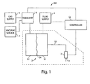
- FIG. 1 is a schematic block diagram of a liquid sample handling apparatus 100 in accordance with the invention.
- one or more needles 1 may pick or place liquid samples on one or more work areas, such as wells in a microtiter tray, a gel containing separated DNA fragments or other biologic materials, etc. Any suitable sample type may be handled by the needle 1, including regents, DNA fragments, proteins, biologic cells, etc.
- Control of fluid flow at the needle I is performed, at least in part, using a valve 2 that is fluidly coupled to a chamber 3 via a conduit 33.
- the chamber 3 has a first portion 31 separated from a second portion 32 by a diaphragm 34.
- the diaphragm 34 may include a flexible member, such as a sheet of elastomeric material. Alternately, the diaphragm 34 may be any suitable material or device that transmits pressure between the first and second portions 31 and 32. In one embodiment, the diaphragm 34 is arranged so that a gas pressure in the second portion 32 is transferred to the first portion 31 so the pressures in both portions are balanced, e.g., equal to each other.
- the first portion 31 may be filled with liquid from a fluid supply 4, such as a fluid tank or other reservoir.
- the liquid may completely fill the first portion 31 as well as the conduit 33 up to the valve 2.
- the liquid in the first portion 31 may be any suitable liquid, such as distilled water, a liquid reagent or other material.
- the second portion 32 may be entirely filled with a gas, such as air.
- the gas may be provided to the second portion 32 via a variable pressure supply that can adjust the pressure in the second portion 32 as desired.
- the variable pressure supply in this embodiment includes a regulator 5 that may control the pressure of the gas in the second portion 32.
- the regulator 5 is a servo-controlled regulator that uses feedback, e.g., from a pressure sensor, to maintain a desired pressure in the first and/or second portion 31, 32 under the control of the controller 10.
- the variable pressure supply may also include a gas supply 6 and/or a vacuum source 7 coupled with the regulator 5 and/or the second portion 32 to help adjust the pressure in the second portion 32.
- gas from the gas supply 6 may be provided to the second portion 32 until the desired pressure is obtained.
- the second portion 32 may be coupled to the vacuum source 7 so gas is removed from the second portion 32 and the pressure is suitably decreased.
- the gas supply 6 and the vacuum source 7 may include any suitable components to provide a pressure source or a vacuum source.
- the gas supply 6 may include a compressor, pump, tank of compressed gas or other.
- the vacuum source 7 may include a vacuum pump, a venturi-type vacuum device, or other suitable arrangement.
- the regulator 5 may also take any suitable form so that the pressure in the second portion 32 may be accurately controlled.
- the valve 2, fluid supply 4, regulator 5 and any other suitable portions of the sample handling apparatus 100 may be controlled by a controller 10. That is, the controller 10 may output and receive signals with respect to components in the system 100 so that the system 100 operates as desired to aspirate and dispense samples.
- the controller 10 may send and receive signals in any suitable way, such as by wired and/or wireless link, and in any suitable format and/or communications protocol.
- the controller 10 may include any suitable general purpose data processing system, which can be, or include a suitably programmed general purpose computer, or network of general purpose computers and other associated devices. Such associated devices may include communication devices and/or other circuitry or components necessary to perform the desired input/output or other functions.
- the controller 10 may also be implemented at least in part as single special purpose integrated circuits (e.g.
- ASICs ASICs
- ASICs ASICs
- ASICs ASICs
- ASICs ASICs
- the controller may also be implemented using a plurality of separate dedicated programmable integrated or other electronic circuits or devices, e.g., hard wired electronic or logic circuits, such as discrete element circuits or programmable logic devices.
- the controller may also include other devices, such as information display devices, user input devices such as a keyboard, user pointing device, touch screen or other interface, data storage devices or other electronic circuitry or components.
- the controller 10 may be part of a robot control system that includes a robot arm or other device to move portions of the sample handling system 100 so samples are picked and placed in desired locations.
- the robotic control system may include a machine vision system to help direct the positioning of portions of the device, as is well known in the art.
- the controller 10 may instruct the regulator 5 to adjust the pressure in the second portion 32 so that it is suitably below an ambient pressure.
- the regulator 5 may fluidly couple the second portion 32 to the vacuum source 7 so that a suitably low pressure is established in the second portion 32.
- the relatively low pressure in the second portion 32 may cause the diaphragm 34 to be generally urged toward the left in Figure 1 so the pressure drops in the first portion 31.
- the controller 10 causes the valve 2 to open, liquid may be withdrawn from the conduit 33 into the first portion 31.
- a liquid sample at the needle 1 may be withdrawn, or aspirated, into the needle 1 from a work surface.
- Close control of the pressure in the second portion 32 and/or a time that the valve 2 is effectively opened may allow for precise control of the volume of the sample that is aspirated by the needle 1.
- a gas or air bubble may separate the liquid sample aspirated into the needle 1 from the control liquid in the conduit 33 and the first portion 31.
- liquid from the first portion 31 and conduit 33 may fill a passage through the valve 2 and extend somewhat past the valve 2 towards the needle 1.
- a gas bubble may separate the liquid from a sample in the needle 1. Providing such separation may prevent the sample from contaminating the control liquid in the first portion 31 and/or vice versa.
- the regulator 5 may adjust the pressure in the second portion 32 so it is suitable above an ambient pressure.
- the regulator 5 may fluidly couple the second portion 32 to a gas supply 6 until a desired pressure in the second portion 32 is obtained.
- a relatively high pressure in the second portion 32 may urge the diaphragm 34 to move generally toward the right increasing pressure in the first portion 31 and in the conduit 33.
- the sample dispensed from the needle 1 may be a previously aspirated sample, or a liquid, such as a reagent, in the first portion 31 and the conduit 33 may be dispensed in precise volumes from the needle 1.
- Precise control of the volume of samples aspirated or dispensed may be controlled based on the pressure established in the second portion 32 and/or the timing that the valve 2 is opened.
- the valve 2 opening/closing timing may be controlled by applying a pulsed electrical signal to a solenoid actuator in the valve so the valve is opened and closed at a high frequency, such as 10 Hz or higher.
- a pulsed electrical signal to a solenoid actuator in the valve so the valve is opened and closed at a high frequency, such as 10 Hz or higher.
- the controller 10 may store information that represents an amount of liquid that is passed through the valve for each open/close cycle for a given pressure in the second portion 32.
- the controller may divide the desired sample volume by the volume passed per cycle by the valve to give a total number of cycles that the valve should be opened/closed.
- the controller may then provide the valve with a suitable signal to cause the valve to open/close for the total number of cycles for each dispense/aspirate operation. It will be understood that this is only one example of how volume control may be performed in an illustrative embodiment.
- the controller may use any suitable process to perform desired volume control for samples.
- FIG. 2 is a schematic block diagram of the system 100 in a somewhat more detailed form than that shown in Figure 1 .
- the system 100 may be prepared for use in handling liquid samples by first removing all fluid from the first portion 31, the conduit 33, valve 2 and needle 1.
- a valve 12 may be adjusted to fluidly couple a gas source, such as a source of pressurized carbon dioxide gas 13, to the first portion 31.
- a valve 16 may also be opened so that fluid in the first portion 31 may exit through the valve 16 to a drain 14.
- the valve 2 may also be opened so that pressurized gas forces fluid to exit the conduit 33, valve 2 and needle 1 into a rinsing reservoir or other container 11.
- the first portion 31 may be rinsed with fluid from a fluid supply, such a source of distilled water 41.
- the valve 12 may couple the source of distilled water 41 to the first portion 31 so the first portion 31 is filled with liquid.
- the valve 2 may also be opened so that the conduit 33 and needle 1 may be rinsed with the distilled water or other suitable liquid.
- valves 12, 16 and 2 may be closed and the system may be used for sample handling.
- a valve 51 may couple a gas supply line 61 from the regulator 5 to the second portion 32. This may create a suitable pressure in the second portion 31 so that liquid in the first portion 31 is forced to flow into the conduit 33 and out of the needle 1 when the valve 2 is opened.
- the valve 51 may couple a vacuum supply line 71 to the second portion 32.
- the vacuum source 7 includes a valve 72 that when opened allows a gas under pressure to flow through a venturi-like element that creates a vacuum in line 71. Creation of a suitably low pressure in the second portion 32 may cause fluid to be withdrawn from the conduit 33 and into the needle 1 from a work surface when the valve 2 is opened. As will be understood, liquid samples aspirated at the needle 1 may be dispensed by suitably raising the pressure in the second portion 32 so the sample is dispensed from the needle 1 when the valve 2 is opened.
- the chamber 3 is coupled to only 1 conduit 33 and valve 2
- any suitable number of conduits 33, valves 2 and/or needles 1 may be fluidly coupled to the chamber 3.
- several conduits 33 may be coupled to the first portion 31 and each lead to a corresponding valve to and needle 1.
- This arrangement can allow a sample handling device to individually aspirate or dispense samples at specific needles and/or simultaneously aspirate or dispense samples from several needles 1.
- the valves 2 may be any suitable electrically-control valve or other.
- the valves 2 may be solenoid valves capable of dispensing approximately 10 nanoliter or larger size samples offered by The Lee Company of Westbrook, CT. Such valves may be opened and closed at high frequencies, e.g., up to 1200 Hz, based on a pulsed signal provided from the controller 10. Such operation may allow for precise metering of samples aspirated and/or dispensed by a needle coupled to the valve.
- the needles may also be of any suitable type and/or size.
- the needles may include jeweled tubes or other channels in which a sapphire or other similar material lines the interior of a stainless steel tube. The needles may alternately receive replaceable tips, e.g., made of plastic.
Landscapes
- Chemical & Material Sciences (AREA)
- Health & Medical Sciences (AREA)
- General Health & Medical Sciences (AREA)
- Life Sciences & Earth Sciences (AREA)
- Analytical Chemistry (AREA)
- Biochemistry (AREA)
- Physics & Mathematics (AREA)
- General Physics & Mathematics (AREA)
- Immunology (AREA)
- Pathology (AREA)
- Clinical Laboratory Science (AREA)
- Chemical Kinetics & Catalysis (AREA)
- Automatic Analysis And Handling Materials Therefor (AREA)
- Sampling And Sample Adjustment (AREA)
Claims (13)
- Flüssigkeitsproben-Handhabungsvorrichtung (100) umfassend:eine Fluidzuführeinrichtung (4); undeine Gleitdruckversorgungseinrichtung (5), die aufgebaut und eingerichtet ist, einen negativen Druck und einen positiven Druck mit Bezug auf einen Umgebungsdruck zu erzeugen; und gekennzeichnet durch:eine Kammer (3) mit einer flexiblen Membran (34), die einen ersten und einen zweiten Abschnitt (31, 32) in der Kammer (3) trennt, wobei der erste Abschnitt (31) mit der Fluidzuführeinrichtung (4) in Fluidkommunikation ist und der zweite Abschnitt (32) mit der Gleitdruckversorgungseinrichtung (5) in Kommunikation ist;ein Ventil (2) in Fluidkommunikation (33) mit dem ersten Abschnitt (31) der Kammer (3); undeine Nadel (1) in Fluidkommunikation mit dem Ventil (2);wobei ein negativer Druck in dem zweiten Abschnitt (32) bewirkt, dass die Nadel (1) eine Fluidprobe ansaugt, wenn das Ventil (2) geöffnet ist, und ein positiver Druck in dem zweiten Abschnitt (32) bewirkt, dass die Nadel (1) eine Fluidprobe abgibt, wenn das Ventil (2) geöffnet ist.
- Vorrichtung nach Anspruch 1, bei der die Gleitdruckversorgungseinrichtung einen servogesteuerten Regulator (5) beinhaltet, der einen Gasdruck in dem zweiten Abschnitt (32) der Kammer (3) steuert.
- Vorrichtung (100) nach einem der vorhergehenden Ansprüche, bei der die Gleitdruckversorgungseinrichtung eine Vakuumquelle (7), die einen Gasdruck unterhalb eines Umgebungsdrucks erzeugt, und eine Gaszuführeinrichtung (6), die einen Gasdruck oberhalb eines Umgebungsdrucks erzeugt, beinhaltet.
- Vorrichtung (100) nach einem der vorhergehenden Ansprüche, ferner umfassend:eine Steuereinrichtung (10), die den Betrieb des Ventils (2) zum Öffnen und Schließen und den Druck in dem zweiten Abschnitt (32) der Kammer (3) steuert.
- Vorrichtung (100) nach einem der vorhergehenden Ansprüche, bei der das Ventil (2) ein Magnetventil mit einem Eingang und einem Ausgang ist, wobei das Magnetventil eingerichtet ist, einen Durchlass zwischen dem Eingang und dem Ausgang zu öffnen und zu schließen;
ein Kanal (33) den ersten Abschnitt (31) der Kammer (3) mit dem Eingang des Magnetventils (2) in Fluidkopplung bringt; und
die Nadel (1) mit dem Ausgang des Magnetventils (2) in Fluidkommunikation ist. - Vorrichtung (100) nach einem der vorhergehenden Ansprüche, bei der die Nadel (1) und das Ventil (2) aufgebaut und eingerichtet sind, Flüssigkeitsproben mit Nanolitergröße anzusaugen und abzugeben.
- Vorrichtung (100) nach einem der vorhergehenden Ansprüche, bei der:die Gleitdruckversorgungseinrichtung (5) einen gesteuerten Gasdruck in dem zweiten Abschnitt (32) der Kammer (3) erzeugt.
- Vorrichtung (100) nach einem der vorhergehenden Ansprüche, ferner umfassend:mehrere Nadeln (1), von denen jede zu einem entsprechenden Ventil (2) in Fluidkommunikation mit dem ersten Abschnitt (31) der Kammer (3) gehört, wobei die Nadeln (1) in einem Muster angeordnet sind, um mit Vertiefungen in einer Mikrotiterplatte zusammenzuwirken.
- Vorrichtung (100) nach Anspruch 8, ferner umfassend:eine Robotereinrichtung, welche die Nadeln (1) relativ zu einer Arbeitsfläche bewegt, so dass Flüssigkeitsproben an gewünschten Stellen angesaugt und abgegeben werden.
- Vorrichtung (100) nach einem der vorhergehenden Ansprüche, bei der die flexible Membran (34) ein Blatt aus elastomerem Material beinhaltet.
- Vorrichtung (100) nach einem der vorhergehenden Ansprüche, bei der das Ventil (2) gesteuert wird, mit einer hohen Frequenz zu öffnen und zu schließen.
- Vorrichtung (100) nach einem der vorhergehenden Ansprüche, bei der die Nadel (1) eine edelsteinbesetzte Röhre beinhaltet.
- Verfahren zur Handhabung von Flüssigkeitsproben unter Verwendung eines robotisch betätigten Werkzeugs, wobei das Verfahren umfasst:Erhöhen eines Gasdrucks in einem Reservoir (3), so dass in dem Reservoir (3) enthaltenes Fluid beaufschlagt wird, sich aus dem Reservoir (3) heraus und in einen Kanal (33), der mit dem Reservoir (3) verbunden ist, zu bewegen;Öffnen eines Ventils (2), das den Fluss durch den Kanal (33) steuert;Abgeben einer Fluidprobe aus einem Probenhandhabungskanal (1), der mit dem Kanal (33) in Fluidkopplung ist;Senken eines Gasdrucks in dem Reservoir (3), so dass in dem mit dem Reservoir (3) verbundenen Kanal (33) enthaltenes Fluid beaufschlagt wird, sich in das Reservoir (3) zu bewegen;Öffnen eines Ventils (2), das den Fluss durch den Kanal (33) steuert; undAnsaugen einer Fluidprobe in den Probenhandhabungskanal (1).
Applications Claiming Priority (2)
| Application Number | Priority Date | Filing Date | Title |
|---|---|---|---|
| US10/641,523 US7097070B2 (en) | 2003-08-15 | 2003-08-15 | Method and apparatus for handling small volume fluid samples |
| PCT/US2004/026453 WO2005016535A1 (en) | 2003-08-15 | 2004-08-13 | Method and apparatus for handling small volume fluid samples |
Publications (2)
| Publication Number | Publication Date |
|---|---|
| EP1663494A1 EP1663494A1 (de) | 2006-06-07 |
| EP1663494B1 true EP1663494B1 (de) | 2009-12-30 |
Family
ID=34136375
Family Applications (1)
| Application Number | Title | Priority Date | Filing Date |
|---|---|---|---|
| EP04781179A Expired - Lifetime EP1663494B1 (de) | 2003-08-15 | 2004-08-13 | Verfahren und vorrichtung zur handhabung von kleinvolumigen fluidproben |
Country Status (7)
| Country | Link |
|---|---|
| US (1) | US7097070B2 (de) |
| EP (1) | EP1663494B1 (de) |
| JP (1) | JP2007502986A (de) |
| AT (1) | ATE453451T1 (de) |
| DE (1) | DE602004024899D1 (de) |
| DK (1) | DK1663494T3 (de) |
| WO (1) | WO2005016535A1 (de) |
Families Citing this family (11)
| Publication number | Priority date | Publication date | Assignee | Title |
|---|---|---|---|---|
| US7534081B2 (en) * | 2005-05-24 | 2009-05-19 | Festo Corporation | Apparatus and method for transferring samples from a source to a target |
| US7597520B2 (en) * | 2005-05-24 | 2009-10-06 | Festo Corporation | Apparatus and method for transferring samples from a source to a target |
| US7799281B2 (en) * | 2007-01-16 | 2010-09-21 | Festo Corporation | Flux concentrator for biomagnetic particle transfer device |
| US8113390B2 (en) * | 2007-04-18 | 2012-02-14 | Microlin, Llc | Gas generation dispenser apparatus and method for on-demand fluid delivery |
| US20100176214A1 (en) * | 2009-01-13 | 2010-07-15 | Joshi Ashok V | Greeting card fragrance delivery system |
| EP2714102B1 (de) | 2011-06-03 | 2018-10-10 | Microlin, LLC | Vorrichtung zur abgabe flüchtiger flüssigkeiten in eine gasförmige umgebung |
| EP2796536B1 (de) * | 2011-12-22 | 2017-08-09 | Panasonic Healthcare Holdings Co., Ltd. | Spendervorrichtung |
| EP3043156B1 (de) * | 2015-01-07 | 2018-03-07 | CSEM Centre Suisse d'Electronique et de Microtechnique SA - Recherche et Développement | Verfahren zur Abgabe oder Ansaugung von Flüssigkeit |
| US11320295B2 (en) * | 2019-04-26 | 2022-05-03 | Festo Se & Co. Kg | Dosing unit and method for dosing a liquid |
| CN112834770B (zh) * | 2019-11-22 | 2025-02-18 | 山西恒昌荣医疗器械有限公司 | 一种用于血栓弹力图仪的前处理设备 |
| JP7495867B2 (ja) * | 2020-10-30 | 2024-06-05 | 株式会社日立ハイテク | 自動分析装置 |
Family Cites Families (134)
| Publication number | Priority date | Publication date | Assignee | Title |
|---|---|---|---|---|
| US2264564A (en) | 1937-10-28 | 1941-12-02 | Connor Arthur Albert | Air brush for artists' use |
| US3575220A (en) | 1968-08-12 | 1971-04-20 | Scientific Industries | Apparatus for dispensing liquid sample |
| US4083690A (en) | 1975-10-02 | 1978-04-11 | Kirin Beer Kabushiki Kaisha | Automatic preparation of sample for analysis |
| US4042152A (en) | 1975-11-21 | 1977-08-16 | Coulter Electronics, Inc. | Diluting apparatus |
| US4058367A (en) | 1976-05-19 | 1977-11-15 | Gilford Instrument Laboratories Inc. | Automatic asynchronous fluid processing apparatus |
| US4152390A (en) | 1976-12-17 | 1979-05-01 | Eastman Kodak Company | Chemical analyzer |
| JPS55136958A (en) | 1979-04-14 | 1980-10-25 | Olympus Optical Co Ltd | Automatic analyzer |
| US4325910A (en) | 1979-07-11 | 1982-04-20 | Technicraft, Inc. | Automated multiple-purpose chemical-analysis apparatus |
| US4352780A (en) | 1979-07-13 | 1982-10-05 | Fiatron Systems, Inc. | Device for controlled injection of fluids |
| US4311484A (en) | 1980-04-09 | 1982-01-19 | Cortex Research Corporation | Specimen sampling apparatus |
| US4323537A (en) | 1980-10-20 | 1982-04-06 | Instrumentation Laboratory Inc. | Analysis system |
| US4351799A (en) | 1981-07-15 | 1982-09-28 | Gross Valery N | Micrometering liquid sample dispenser |
| US4436822A (en) | 1981-09-22 | 1984-03-13 | Sherwood Medical Company | Reagent mixing system and method |
| US4482345A (en) | 1982-02-16 | 1984-11-13 | E. R. Squibb & Sons, Inc. | Automated control for a two-directional pump |
| US4454095A (en) | 1982-07-21 | 1984-06-12 | Harbor Branch Foundation, Inc. | Automatic chemical analysis devices and methods |
| US4597412A (en) | 1982-09-29 | 1986-07-01 | Stark Anton W | Valve for sequential chemical operations |
| US4503012A (en) | 1983-04-19 | 1985-03-05 | American Monitor Corporation | Reagent dispensing system |
| US4673657A (en) | 1983-08-26 | 1987-06-16 | The Regents Of The University Of California | Multiple assay card and system |
| US5273715A (en) | 1984-03-23 | 1993-12-28 | Applied Biosystems, Inc. | Automated system for providing a sequence of chemicals to a reaction process |
| US4876204A (en) | 1984-10-11 | 1989-10-24 | Kabushiki Kaisha Kyoto Daiichi Kagaku | Method and apparatus of automatic continuous analysis using analytical implement |
| JPS61198041A (ja) | 1985-02-28 | 1986-09-02 | Konishiroku Photo Ind Co Ltd | 生化学分析装置 |
| EP0216026B1 (de) | 1985-06-26 | 1992-01-22 | Japan Tectron Instruments Corporation | Automatischer Analysenapparat |
| US4681741A (en) | 1985-07-01 | 1987-07-21 | American Hospital Supply Corporation | Reagent dispenser for an analyzing system |
| US4695430A (en) | 1985-10-31 | 1987-09-22 | Bio/Data Corporation | Analytical apparatus |
| US4863066A (en) * | 1986-06-02 | 1989-09-05 | Technicon Instruments Corporation | System for dispensing precisely metered quantities of a fluid and method of utilizing the system |
| US4965049A (en) | 1986-07-11 | 1990-10-23 | Beckman Instruments, Inc. | Modular analyzer system |
| US4911195A (en) | 1986-08-27 | 1990-03-27 | Porton Instruments, Inc. | Valve block assembly |
| GB2196116B (en) | 1986-10-07 | 1990-08-15 | Weston Terence E | Apparatus for chemical analysis. |
| US4980130A (en) | 1986-12-16 | 1990-12-25 | Ciba-Geigy Corporation | System for preparation of samples for analysis |
| US4844872A (en) | 1987-07-17 | 1989-07-04 | Fisher Scientific Company | Fluid handling |
| US4906432B1 (en) | 1987-07-17 | 1991-06-25 | Liquid handling | |
| JPH06103315B2 (ja) | 1987-08-14 | 1994-12-14 | 株式会社東芝 | 自動化学分析装置の分注ノズル装置 |
| US5139743A (en) | 1987-09-24 | 1992-08-18 | Fuji Photo Film Co., Ltd. | Biochemical analysis apparatus |
| US5147608A (en) | 1988-04-29 | 1992-09-15 | Millipore Corporation | Apparatus and process for performing repetitive chemical processing |
| US5019348A (en) | 1988-05-26 | 1991-05-28 | Beckman Instruments, Inc. | Automated chemical conversion unit in a peptide/protein sequenator |
| US4900305A (en) | 1988-06-27 | 1990-02-13 | Queen's University At Kingston | Ambulatory infusion pump |
| US5012845A (en) | 1988-08-18 | 1991-05-07 | Dynatech Precision Sampling Corporation | Fluid injector |
| US6306594B1 (en) | 1988-11-14 | 2001-10-23 | I-Stat Corporation | Methods for microdispensing patterened layers |
| US5037611A (en) | 1988-11-29 | 1991-08-06 | Icr Research Associates, Inc. | Sample handling technique |
| IT1228238B (it) | 1989-01-16 | 1991-06-05 | Nardo Pietro C | Apparecchiatura per il trattamento di schede elettroforetiche. |
| US5213762A (en) | 1989-03-13 | 1993-05-25 | Beckman Instruments, Inc. | Automatic chemistry analyzer |
| US5223222A (en) | 1989-03-13 | 1993-06-29 | Beckman Instruments, Inc. | Automatic chemistry analyzer |
| US5130095A (en) | 1989-03-13 | 1992-07-14 | Beckman Instruments, Inc. | Automatic chemistry analyzer |
| JPH02242162A (ja) | 1989-03-15 | 1990-09-26 | Takara Shuzo Co Ltd | 試薬反応装置 |
| US5056462A (en) | 1989-11-27 | 1991-10-15 | Nordson Corporation | Coating system with correction for non-linear dispensing characteristics |
| US5595707A (en) | 1990-03-02 | 1997-01-21 | Ventana Medical Systems, Inc. | Automated biological reaction apparatus |
| US5282978A (en) | 1990-07-09 | 1994-02-01 | Cytyc Corporation | Specimen processor method and apparatus |
| US5085832A (en) | 1990-07-20 | 1992-02-04 | Eastman Kodak Company | Dispensing mechanism |
| DE4024545A1 (de) | 1990-08-02 | 1992-02-06 | Boehringer Mannheim Gmbh | Verfahren und vorrichtung zum dosierten zufuehren einer biochemischen analysefluessigkeit auf ein target |
| US5085402A (en) | 1990-08-10 | 1992-02-04 | The Lee Company | High speed solenoid valve actuator |
| US5143118A (en) | 1991-02-14 | 1992-09-01 | Akos Sule | Solenoid control valve |
| CA2099282A1 (en) | 1991-10-31 | 1993-05-01 | Microscan, Inc. | Specimen processing and analyzing systems with associated fluid dispensing apparatus |
| US5240680A (en) | 1991-12-19 | 1993-08-31 | Chiron Corporation | Automated apparatus for use in peptide synthesis |
| US5635364A (en) | 1992-03-27 | 1997-06-03 | Abbott Laboratories | Assay verification control for an automated analytical system |
| US5646049A (en) | 1992-03-27 | 1997-07-08 | Abbott Laboratories | Scheduling operation of an automated analytical system |
| US5332549A (en) | 1992-07-01 | 1994-07-26 | Pb Diagnostic Systems, Inc. | Assay module transport apparatus for use in an automated analytical instrument |
| US5314825A (en) | 1992-07-16 | 1994-05-24 | Schiapparelli Biosystems, Inc. | Chemical analyzer |
| US5284425A (en) | 1992-11-18 | 1994-02-08 | The Lee Company | Fluid metering pump |
| US5324480A (en) | 1992-12-04 | 1994-06-28 | Hamilton Company | Liquid handling system |
| US5507277A (en) | 1993-01-29 | 1996-04-16 | Aradigm Corporation | Lockout device for controlled release of drug from patient-activateddispenser |
| US5525515A (en) | 1993-02-03 | 1996-06-11 | Blattner; Frederick R. | Process of handling liquids in an automated liquid handling apparatus |
| US5334353A (en) | 1993-02-03 | 1994-08-02 | Blattner Frederick R | Micropipette device |
| US5320139A (en) | 1993-03-30 | 1994-06-14 | Millipore Corporation | Fluid delivery system |
| EP0636413B1 (de) | 1993-07-28 | 2001-11-14 | PE Corporation (NY) | Vorrichtung und Verfahren zur Nukleinsäurevervielfältigung |
| RU2041263C1 (ru) | 1993-08-11 | 1995-08-09 | Геннадий Моисеевич Ершов | Способ микродозирования водных растворов веществ на носитель и устройство для его осуществления |
| US5509966A (en) | 1993-10-22 | 1996-04-23 | Sykes; Richard H. | Graphic arts material extrusion device |
| US5411065A (en) | 1994-01-10 | 1995-05-02 | Kvm Technologies, Inc. | Liquid specimen transfer apparatus and method |
| JP3364311B2 (ja) | 1994-03-15 | 2003-01-08 | シスメックス株式会社 | 定量装置 |
| US5624409A (en) | 1994-06-10 | 1997-04-29 | Fluidsense Corporation | Variable-pulse dynamic fluid flow controller |
| US5948360A (en) | 1994-07-11 | 1999-09-07 | Tekmar Company | Autosampler with robot arm |
| US5549141A (en) | 1994-07-19 | 1996-08-27 | Kvm Technologies, Inc. | Liquid container sample transfer method and apparatus |
| US6558633B1 (en) | 1994-09-21 | 2003-05-06 | Isis Pharmaceuticals, Inc. | Chemical reaction apparatus and methods |
| JP3229915B2 (ja) | 1995-01-19 | 2001-11-19 | 日本電子株式会社 | 生化学自動分析装置 |
| US5568882A (en) | 1995-02-03 | 1996-10-29 | Abc Techcorp | Precise volume fluid dispenser |
| US5601982A (en) | 1995-02-07 | 1997-02-11 | Sargent; Jeannine P. | Method and apparatus for determining the sequence of polynucleotides |
| CA2185292A1 (en) | 1995-09-15 | 1997-03-16 | James C. Smith | Positive displacement liquid drawing and dispensing apparatus and method |
| US5797515A (en) | 1995-10-18 | 1998-08-25 | Adds, Inc. | Method for controlling a drug dispensing system |
| US5763278A (en) | 1995-11-01 | 1998-06-09 | Tecan Ag | Automated pipetting of small volumes |
| US5762873A (en) | 1996-02-21 | 1998-06-09 | Biomerieux Vitek, Inc. | Automatic sample testing machine |
| US5697409A (en) | 1996-02-21 | 1997-12-16 | Biomerieux Vitek, Inc. | Diluting and pipetting stations for sample testing machine |
| US5819799A (en) | 1996-05-10 | 1998-10-13 | The Lee Company | Method and apparatus for rapid fluid dispensing |
| US5770151A (en) | 1996-06-05 | 1998-06-23 | Molecular Dynamics, Inc. | High-speed liquid deposition device for biological molecule array formation |
| US5738728A (en) | 1996-07-26 | 1998-04-14 | Bio Dot, Inc. | Precision metered aerosol dispensing apparatus |
| US5916524A (en) | 1997-07-23 | 1999-06-29 | Bio-Dot, Inc. | Dispensing apparatus having improved dynamic range |
| US5741554A (en) | 1996-07-26 | 1998-04-21 | Bio Dot, Inc. | Method of dispensing a liquid reagent |
| US5743960A (en) | 1996-07-26 | 1998-04-28 | Bio-Dot, Inc. | Precision metered solenoid valve dispenser |
| US5856194A (en) | 1996-09-19 | 1999-01-05 | Abbott Laboratories | Method for determination of item of interest in a sample |
| US5795784A (en) | 1996-09-19 | 1998-08-18 | Abbott Laboratories | Method of performing a process for determining an item of interest in a sample |
| US5882903A (en) | 1996-11-01 | 1999-03-16 | Sarnoff Corporation | Assay system and method for conducting assays |
| EP0957954B1 (de) | 1996-11-22 | 2003-05-28 | Therakos, Inc. | Vorrichtung zum pumpen eines fluides mit einer konstanten durchflussrate |
| US5897837A (en) | 1997-02-06 | 1999-04-27 | Toa Medical Electronics Co., Ltd. | Dispensing device and Immunoassay apparatus using the same |
| US5875967A (en) | 1997-02-07 | 1999-03-02 | The Lee Company | Method and apparatus for dispensing fluid having volatile solvent |
| US5985214A (en) | 1997-05-16 | 1999-11-16 | Aurora Biosciences Corporation | Systems and methods for rapidly identifying useful chemicals in liquid samples |
| US5993627A (en) | 1997-06-24 | 1999-11-30 | Large Scale Biology Corporation | Automated system for two-dimensional electrophoresis |
| US6045759A (en) | 1997-08-11 | 2000-04-04 | Ventana Medical Systems | Fluid dispenser |
| DE19737173B4 (de) | 1997-08-26 | 2007-04-05 | Eppendorf Ag | Mikrodosiersystem |
| US6102068A (en) | 1997-09-23 | 2000-08-15 | Hewlett-Packard Company | Selector valve assembly |
| IL121968A0 (en) | 1997-10-14 | 1998-03-10 | A R T Medical Instr Ltd | Method for depositing a microvolume of liquid on a surface and apparatus therefor and a microvolume pump therefor |
| KR100279552B1 (ko) | 1997-10-18 | 2001-11-30 | 박한오 | 다중단속밸브장치 |
| US5928131A (en) | 1997-11-26 | 1999-07-27 | Vascor, Inc. | Magnetically suspended fluid pump and control system |
| US6063339A (en) | 1998-01-09 | 2000-05-16 | Cartesian Technologies, Inc. | Method and apparatus for high-speed dot array dispensing |
| US20020159919A1 (en) | 1998-01-09 | 2002-10-31 | Carl Churchill | Method and apparatus for high-speed microfluidic dispensing using text file control |
| DE19802368C1 (de) | 1998-01-22 | 1999-08-05 | Hahn Schickard Ges | Mikrodosiervorrichtung |
| WO1999042804A2 (en) | 1998-02-20 | 1999-08-26 | Cartesian Technologies, Inc. | Methods for microfluidic aspirating and dispensing |
| US6537505B1 (en) | 1998-02-20 | 2003-03-25 | Bio Dot, Inc. | Reagent dispensing valve |
| EP1129008A4 (de) | 1998-07-07 | 2001-12-05 | Cartesian Technology Inc | Spitzengestaltung und direktzugriffsmatrix für mikro-flüssigkeitstransfer |
| US6913934B2 (en) | 1998-08-13 | 2005-07-05 | Symyx Technologies, Inc. | Apparatus and methods for parallel processing of multiple reaction mixtures |
| JP3525757B2 (ja) | 1998-09-18 | 2004-05-10 | 株式会社日立製作所 | 化学分析装置 |
| AU3355400A (en) | 1999-02-05 | 2000-08-25 | Invitrogen Corporation | System, method and computer program product for automated fluid or gas delivery |
| US6432719B1 (en) | 1999-02-16 | 2002-08-13 | Pe Corporation (Ny) | Matrix storage and dispensing system |
| US6627157B1 (en) | 1999-03-04 | 2003-09-30 | Ut-Battelle, Llc | Dual manifold system and method for fluid transfer |
| US20020176801A1 (en) | 1999-03-23 | 2002-11-28 | Giebeler Robert H. | Fluid delivery and analysis systems |
| US6143252A (en) | 1999-04-12 | 2000-11-07 | The Perkin-Elmer Corporation | Pipetting device with pipette tip for solid phase reactions |
| US6245297B1 (en) | 1999-04-16 | 2001-06-12 | Pe Corporation (Ny) | Apparatus and method for transferring small volumes of substances |
| FR2793261B1 (fr) | 1999-05-05 | 2001-08-17 | Genomic | Procede et dispositif pour l'extraction d'adn, d'arn et de proteines a partir de prelevement biologiques |
| US6448090B1 (en) | 1999-07-09 | 2002-09-10 | Orchid Biosciences, Inc. | Fluid delivery system for a microfluidic device using alternating pressure waveforms |
| US6395232B1 (en) | 1999-07-09 | 2002-05-28 | Orchid Biosciences, Inc. | Fluid delivery system for a microfluidic device using a pressure pulse |
| US6429016B1 (en) | 1999-10-01 | 2002-08-06 | Isis Pharmaceuticals, Inc. | System and method for sample positioning in a robotic system |
| EP1099483B1 (de) | 1999-11-11 | 2009-02-11 | Allegro Technologies Limited | Abgabe von flüssigen Tropfen |
| AU2001234739A1 (en) | 2000-02-02 | 2001-08-14 | Cartesian Technologies, Inc. | Method and apparatus for developing dna microarrays |
| US6932895B2 (en) | 2000-02-15 | 2005-08-23 | Large Scale Proteomics Corporation | Automated electrophoresis gel manipulation apparatus |
| US7160511B2 (en) | 2000-02-18 | 2007-01-09 | Olympus Corporation | Liquid pipetting apparatus and micro array manufacturing apparatus |
| US6387330B1 (en) | 2000-04-12 | 2002-05-14 | George Steven Bova | Method and apparatus for storing and dispensing reagents |
| US6431212B1 (en) | 2000-05-24 | 2002-08-13 | Jon W. Hayenga | Valve for use in microfluidic structures |
| AU2001265421A1 (en) | 2000-06-05 | 2001-12-17 | Nordson Corporation | Apparatus and methods for dispensing minute amounts of liquid |
| US6913879B1 (en) | 2000-07-10 | 2005-07-05 | Telechem International Inc. | Microarray method of genotyping multiple samples at multiple LOCI |
| WO2002018053A1 (en) | 2000-08-30 | 2002-03-07 | Cartesian Technologies, Inc. | Method and apparatus for high-speed microfluidic dispensing using text file control |
| US6852291B1 (en) | 2000-10-11 | 2005-02-08 | Innovadyne Technologies, Inc. | Hybrid valve apparatus and method for fluid handling |
| EP1332000B1 (de) | 2000-10-30 | 2012-06-20 | Sequenom, Inc. | Verfahren zur aufbringung von submikroliter fluid-volumina auf ein substrat |
| US6360794B1 (en) | 2000-12-19 | 2002-03-26 | Bechtel Bwxt Idaho, Llc | Apparatus and method for delivering a fluid to a container |
| JP2002228669A (ja) | 2001-01-31 | 2002-08-14 | Shimadzu Corp | 液体移送器及び反応容器 |
| US6659142B2 (en) | 2001-03-27 | 2003-12-09 | Irm, Llc | Apparatus and method for preparing fluid mixtures |
| EP1414585A4 (de) | 2001-04-04 | 2007-03-07 | Arradial Inc | System und verfahren zur ausgabe von flüssigkeiten |
| US6982063B2 (en) | 2001-05-25 | 2006-01-03 | Matrix Technologies Corp | Automated pipetting system |
-
2003
- 2003-08-15 US US10/641,523 patent/US7097070B2/en not_active Expired - Lifetime
-
2004
- 2004-08-13 JP JP2006523951A patent/JP2007502986A/ja active Pending
- 2004-08-13 DK DK04781179.9T patent/DK1663494T3/da active
- 2004-08-13 DE DE602004024899T patent/DE602004024899D1/de not_active Expired - Lifetime
- 2004-08-13 WO PCT/US2004/026453 patent/WO2005016535A1/en not_active Ceased
- 2004-08-13 AT AT04781179T patent/ATE453451T1/de not_active IP Right Cessation
- 2004-08-13 EP EP04781179A patent/EP1663494B1/de not_active Expired - Lifetime
Also Published As
| Publication number | Publication date |
|---|---|
| US7097070B2 (en) | 2006-08-29 |
| WO2005016535A1 (en) | 2005-02-24 |
| EP1663494A1 (de) | 2006-06-07 |
| ATE453451T1 (de) | 2010-01-15 |
| DK1663494T3 (da) | 2010-04-26 |
| JP2007502986A (ja) | 2007-02-15 |
| US20050035143A1 (en) | 2005-02-17 |
| DE602004024899D1 (de) | 2010-02-11 |
Similar Documents
| Publication | Publication Date | Title |
|---|---|---|
| EP1539352B1 (de) | Flüssigkeitshandhabungsinstrument mit einem hohlen kolben | |
| EP1663494B1 (de) | Verfahren und vorrichtung zur handhabung von kleinvolumigen fluidproben | |
| US5525515A (en) | Process of handling liquids in an automated liquid handling apparatus | |
| US5865224A (en) | Method and apparatus for automated dispensing | |
| JP5980030B2 (ja) | 生化学処理装置 | |
| US20050208676A1 (en) | Device for aspirating, manipulating, mixing and dispensing nano-volumes of liquids | |
| US20040146433A1 (en) | Sample handling tool with piezoelectric actuator | |
| EP1493036B1 (de) | Robotisch manipulierbares proben-verarbeitungswerkzeug | |
| WO1998028189A9 (en) | Method and apparatus for automated dispensing | |
| CN109937365A (zh) | 移液方法以及移液装置 | |
| EP1333287A3 (de) | Verfahren und Vorrichtung zur Druckänderung in einem Flüssigkeitspender | |
| US10962560B2 (en) | Pipetting arrangement and method of controlling a pipetting arrangement or of producing liquid product doses | |
| US7249529B2 (en) | Robotically manipulable sample handling tool | |
| JP4762240B2 (ja) | マルチウェルプレートのウェルの中の内容物を動かすための方法と装置 | |
| EP4431187A1 (de) | Pneumatischer kreislauf | |
| CN110893354A (zh) | 一种多模块的乳液微滴生成控制装置 | |
| US20070107780A1 (en) | Fluid handling device | |
| WO2020259816A1 (en) | Cartridge, electrowetting sample processing system and feeding thereof | |
| EP3381555A1 (de) | Flüssigkeitsbehandlungs- und/oder verteilungssystem und verfahren | |
| JPH03168369A (ja) | 理化学機械用送液装置 |
Legal Events
| Date | Code | Title | Description |
|---|---|---|---|
| PUAI | Public reference made under article 153(3) epc to a published international application that has entered the european phase |
Free format text: ORIGINAL CODE: 0009012 |
|
| 17P | Request for examination filed |
Effective date: 20060314 |
|
| AK | Designated contracting states |
Kind code of ref document: A1 Designated state(s): AT BE BG CH CY CZ DE DK EE ES FI FR GB GR HU IE IT LI LU MC NL PL PT RO SE SI SK TR |
|
| DAX | Request for extension of the european patent (deleted) | ||
| GRAP | Despatch of communication of intention to grant a patent |
Free format text: ORIGINAL CODE: EPIDOSNIGR1 |
|
| GRAS | Grant fee paid |
Free format text: ORIGINAL CODE: EPIDOSNIGR3 |
|
| GRAA | (expected) grant |
Free format text: ORIGINAL CODE: 0009210 |
|
| AK | Designated contracting states |
Kind code of ref document: B1 Designated state(s): AT BE BG CH CY CZ DE DK EE ES FI FR GB GR HU IE IT LI LU MC NL PL PT RO SE SI SK TR |
|
| REG | Reference to a national code |
Ref country code: GB Ref legal event code: FG4D |
|
| REG | Reference to a national code |
Ref country code: CH Ref legal event code: EP |
|
| REG | Reference to a national code |
Ref country code: IE Ref legal event code: FG4D |
|
| REF | Corresponds to: |
Ref document number: 602004024899 Country of ref document: DE Date of ref document: 20100211 Kind code of ref document: P |
|
| REG | Reference to a national code |
Ref country code: SE Ref legal event code: TRGR |
|
| REG | Reference to a national code |
Ref country code: DK Ref legal event code: T3 |
|
| PG25 | Lapsed in a contracting state [announced via postgrant information from national office to epo] |
Ref country code: FI Free format text: LAPSE BECAUSE OF FAILURE TO SUBMIT A TRANSLATION OF THE DESCRIPTION OR TO PAY THE FEE WITHIN THE PRESCRIBED TIME-LIMIT Effective date: 20091230 |
|
| REG | Reference to a national code |
Ref country code: NL Ref legal event code: VDEP Effective date: 20091230 |
|
| PG25 | Lapsed in a contracting state [announced via postgrant information from national office to epo] |
Ref country code: PL Free format text: LAPSE BECAUSE OF FAILURE TO SUBMIT A TRANSLATION OF THE DESCRIPTION OR TO PAY THE FEE WITHIN THE PRESCRIBED TIME-LIMIT Effective date: 20091230 Ref country code: SI Free format text: LAPSE BECAUSE OF FAILURE TO SUBMIT A TRANSLATION OF THE DESCRIPTION OR TO PAY THE FEE WITHIN THE PRESCRIBED TIME-LIMIT Effective date: 20091230 |
|
| PG25 | Lapsed in a contracting state [announced via postgrant information from national office to epo] |
Ref country code: AT Free format text: LAPSE BECAUSE OF FAILURE TO SUBMIT A TRANSLATION OF THE DESCRIPTION OR TO PAY THE FEE WITHIN THE PRESCRIBED TIME-LIMIT Effective date: 20091230 |
|
| PG25 | Lapsed in a contracting state [announced via postgrant information from national office to epo] |
Ref country code: NL Free format text: LAPSE BECAUSE OF FAILURE TO SUBMIT A TRANSLATION OF THE DESCRIPTION OR TO PAY THE FEE WITHIN THE PRESCRIBED TIME-LIMIT Effective date: 20091230 Ref country code: EE Free format text: LAPSE BECAUSE OF FAILURE TO SUBMIT A TRANSLATION OF THE DESCRIPTION OR TO PAY THE FEE WITHIN THE PRESCRIBED TIME-LIMIT Effective date: 20091230 Ref country code: PT Free format text: LAPSE BECAUSE OF FAILURE TO SUBMIT A TRANSLATION OF THE DESCRIPTION OR TO PAY THE FEE WITHIN THE PRESCRIBED TIME-LIMIT Effective date: 20100430 Ref country code: BG Free format text: LAPSE BECAUSE OF FAILURE TO SUBMIT A TRANSLATION OF THE DESCRIPTION OR TO PAY THE FEE WITHIN THE PRESCRIBED TIME-LIMIT Effective date: 20100330 Ref country code: RO Free format text: LAPSE BECAUSE OF FAILURE TO SUBMIT A TRANSLATION OF THE DESCRIPTION OR TO PAY THE FEE WITHIN THE PRESCRIBED TIME-LIMIT Effective date: 20091230 Ref country code: ES Free format text: LAPSE BECAUSE OF FAILURE TO SUBMIT A TRANSLATION OF THE DESCRIPTION OR TO PAY THE FEE WITHIN THE PRESCRIBED TIME-LIMIT Effective date: 20100410 |
|
| PG25 | Lapsed in a contracting state [announced via postgrant information from national office to epo] |
Ref country code: BE Free format text: LAPSE BECAUSE OF FAILURE TO SUBMIT A TRANSLATION OF THE DESCRIPTION OR TO PAY THE FEE WITHIN THE PRESCRIBED TIME-LIMIT Effective date: 20091230 Ref country code: CZ Free format text: LAPSE BECAUSE OF FAILURE TO SUBMIT A TRANSLATION OF THE DESCRIPTION OR TO PAY THE FEE WITHIN THE PRESCRIBED TIME-LIMIT Effective date: 20091230 Ref country code: SK Free format text: LAPSE BECAUSE OF FAILURE TO SUBMIT A TRANSLATION OF THE DESCRIPTION OR TO PAY THE FEE WITHIN THE PRESCRIBED TIME-LIMIT Effective date: 20091230 |
|
| PG25 | Lapsed in a contracting state [announced via postgrant information from national office to epo] |
Ref country code: CY Free format text: LAPSE BECAUSE OF FAILURE TO SUBMIT A TRANSLATION OF THE DESCRIPTION OR TO PAY THE FEE WITHIN THE PRESCRIBED TIME-LIMIT Effective date: 20091230 Ref country code: GR Free format text: LAPSE BECAUSE OF FAILURE TO SUBMIT A TRANSLATION OF THE DESCRIPTION OR TO PAY THE FEE WITHIN THE PRESCRIBED TIME-LIMIT Effective date: 20100331 |
|
| PLBE | No opposition filed within time limit |
Free format text: ORIGINAL CODE: 0009261 |
|
| STAA | Information on the status of an ep patent application or granted ep patent |
Free format text: STATUS: NO OPPOSITION FILED WITHIN TIME LIMIT |
|
| 26N | No opposition filed |
Effective date: 20101001 |
|
| PG25 | Lapsed in a contracting state [announced via postgrant information from national office to epo] |
Ref country code: MC Free format text: LAPSE BECAUSE OF NON-PAYMENT OF DUE FEES Effective date: 20100831 |
|
| REG | Reference to a national code |
Ref country code: FR Ref legal event code: ST Effective date: 20110502 |
|
| PG25 | Lapsed in a contracting state [announced via postgrant information from national office to epo] |
Ref country code: FR Free format text: LAPSE BECAUSE OF NON-PAYMENT OF DUE FEES Effective date: 20100831 Ref country code: IE Free format text: LAPSE BECAUSE OF NON-PAYMENT OF DUE FEES Effective date: 20100813 |
|
| PG25 | Lapsed in a contracting state [announced via postgrant information from national office to epo] |
Ref country code: LU Free format text: LAPSE BECAUSE OF NON-PAYMENT OF DUE FEES Effective date: 20100813 Ref country code: HU Free format text: LAPSE BECAUSE OF FAILURE TO SUBMIT A TRANSLATION OF THE DESCRIPTION OR TO PAY THE FEE WITHIN THE PRESCRIBED TIME-LIMIT Effective date: 20100701 |
|
| PG25 | Lapsed in a contracting state [announced via postgrant information from national office to epo] |
Ref country code: TR Free format text: LAPSE BECAUSE OF FAILURE TO SUBMIT A TRANSLATION OF THE DESCRIPTION OR TO PAY THE FEE WITHIN THE PRESCRIBED TIME-LIMIT Effective date: 20091230 |
|
| PGFP | Annual fee paid to national office [announced via postgrant information from national office to epo] |
Ref country code: CH Payment date: 20150827 Year of fee payment: 12 Ref country code: DE Payment date: 20150827 Year of fee payment: 12 Ref country code: DK Payment date: 20150825 Year of fee payment: 12 Ref country code: GB Payment date: 20150827 Year of fee payment: 12 |
|
| PGFP | Annual fee paid to national office [announced via postgrant information from national office to epo] |
Ref country code: SE Payment date: 20150827 Year of fee payment: 12 |
|
| PGFP | Annual fee paid to national office [announced via postgrant information from national office to epo] |
Ref country code: IT Payment date: 20150825 Year of fee payment: 12 |
|
| REG | Reference to a national code |
Ref country code: DE Ref legal event code: R119 Ref document number: 602004024899 Country of ref document: DE |
|
| REG | Reference to a national code |
Ref country code: DK Ref legal event code: EBP Effective date: 20160831 |
|
| REG | Reference to a national code |
Ref country code: SE Ref legal event code: EUG |
|
| REG | Reference to a national code |
Ref country code: CH Ref legal event code: PL |
|
| GBPC | Gb: european patent ceased through non-payment of renewal fee |
Effective date: 20160813 |
|
| PG25 | Lapsed in a contracting state [announced via postgrant information from national office to epo] |
Ref country code: LI Free format text: LAPSE BECAUSE OF NON-PAYMENT OF DUE FEES Effective date: 20160831 Ref country code: SE Free format text: LAPSE BECAUSE OF NON-PAYMENT OF DUE FEES Effective date: 20160814 Ref country code: CH Free format text: LAPSE BECAUSE OF NON-PAYMENT OF DUE FEES Effective date: 20160831 |
|
| PG25 | Lapsed in a contracting state [announced via postgrant information from national office to epo] |
Ref country code: DK Free format text: LAPSE BECAUSE OF NON-PAYMENT OF DUE FEES Effective date: 20160831 Ref country code: DE Free format text: LAPSE BECAUSE OF NON-PAYMENT OF DUE FEES Effective date: 20170301 Ref country code: GB Free format text: LAPSE BECAUSE OF NON-PAYMENT OF DUE FEES Effective date: 20160813 |
|
| PG25 | Lapsed in a contracting state [announced via postgrant information from national office to epo] |
Ref country code: IT Free format text: LAPSE BECAUSE OF NON-PAYMENT OF DUE FEES Effective date: 20160813 |