EP1651298B1 - Multi-lumen medical electrical lead body - Google Patents
Multi-lumen medical electrical lead body Download PDFInfo
- Publication number
- EP1651298B1 EP1651298B1 EP04776682A EP04776682A EP1651298B1 EP 1651298 B1 EP1651298 B1 EP 1651298B1 EP 04776682 A EP04776682 A EP 04776682A EP 04776682 A EP04776682 A EP 04776682A EP 1651298 B1 EP1651298 B1 EP 1651298B1
- Authority
- EP
- European Patent Office
- Prior art keywords
- lumen
- lead
- length
- conductor
- section
- Prior art date
- Legal status (The legal status is an assumption and is not a legal conclusion. Google has not performed a legal analysis and makes no representation as to the accuracy of the status listed.)
- Expired - Lifetime
Links
Images


Classifications
-
- A—HUMAN NECESSITIES
- A61—MEDICAL OR VETERINARY SCIENCE; HYGIENE
- A61N—ELECTROTHERAPY; MAGNETOTHERAPY; RADIATION THERAPY; ULTRASOUND THERAPY
- A61N1/00—Electrotherapy; Circuits therefor
- A61N1/02—Details
- A61N1/04—Electrodes
- A61N1/05—Electrodes for implantation or insertion into the body, e.g. heart electrode
- A61N1/056—Transvascular endocardial electrode systems
- A61N1/057—Anchoring means; Means for fixing the head inside the heart
- A61N1/0573—Anchoring means; Means for fixing the head inside the heart chacterised by means penetrating the heart tissue, e.g. helix needle or hook
-
- A—HUMAN NECESSITIES
- A61—MEDICAL OR VETERINARY SCIENCE; HYGIENE
- A61N—ELECTROTHERAPY; MAGNETOTHERAPY; RADIATION THERAPY; ULTRASOUND THERAPY
- A61N1/00—Electrotherapy; Circuits therefor
- A61N1/02—Details
- A61N1/04—Electrodes
- A61N1/05—Electrodes for implantation or insertion into the body, e.g. heart electrode
- A61N1/056—Transvascular endocardial electrode systems
- A61N1/0563—Transvascular endocardial electrode systems specially adapted for defibrillation or cardioversion
Definitions
- Implantable medical devices have long utilized medical electrical leads including elongated lead bodies, which carry one or more conductors coupling stimulation and or sensing electrodes or other types of sensors positioned at a target site to a connector coupled to a pulse generator or diagnostic device.
- a single lead body In order to carry out multiple functions, it is often desirable for a single lead body to carry multiple insulated conductors; however, it is also desirable for the lead body to have as small a profile or diameter as possible, to be flexible for implantation within a body, and to withstand damage under implant-environmental loading.
- the invention provides a medical electrical lead as defined in claim 1.
- US 5 957 970 provides a medical electrical lead according to the preamble of claim 1.
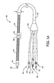
- Figure 1 is a plan view of a medical electrical lead according to one embodiment of the present invention.
- Figure 1 illustrates a medical electrical lead 100 including a lead body 110, a tip electrode 118, a ring electrode 116, and two defibrillation electrodes 112, 114;
- lead body 110 carries at least four conductors (not shown; reference Figure 2A ) to couple tip and ring electrodes 118 and 116 to a contact pin 126 and contact ring 127, respectively, of a connector leg 125 and defibrillation electrodes 112, 114 each to a contact pin 121 or 124 of a connector leg 122 or 123.
- Connector legs 122, 123, and 125, joined to lead body 110 via a trifurcation sleeve 120, are adapted to electrically couple lead 100 to a medical device and may each conform to an industry standard, for example DF-1 or IS-1, such as are known to those skilled in the art; configurations and constructions corresponding to connector legs 122, 123, and 125 are well known to those skilled in the art of lead construction.
- an industry standard for example DF-1 or IS-1
- lead body 110 comprises a multi-lumen tube composed of an elastomeric biocompatible and biostable insulative material, examples of which are well known to those skilled in the art and include silicone, polyurethane, and combinations thereof; one specific example of an appropriate insulative material is HP (high performance) silicone having a durometer between approximately 30 and approximately 70 on a shore A scale.
- Figure 2A is a section view through section line 2-2 of Figure 1 showing an arrangement of lumens and conductors in a multi-lumen tube 20 of lead body 110 according to one embodiment of the present invention.
- Figure 2A illustrates tube 20 including a lumen 21 having an inner surface forming a substantially elliptical cross-section and a plurality of additional lumens 24A, 24B, 24C each having inner surfaces forming substantially circular cross-sections; cable conductors 12, 14, and 26 are shown positioned in lumens 24 and a coil conductor 28 positioned within lumen 21.
- Conductors include any suitable material known in the art of lead construction, for example an MP35N alloy, and are likewise formed according to methods known to those skilled in the art.
- Cable conductors 12, 14, and 26 may include insulative sheaths 27, as illustrated in Figure 2A , each having an outer diameter between approximately 0.005 inch (0.127 mm) and approximately 0.020 inch (0.508 mm) according to embodiments of the present invention.
- FIG 2A further illustrates lead body 110 including an outer overlay sheath 25, which may be formed of a polymer such as polyurethane or silicone or a combination thereof; according to some embodiments of the present invention overlay sheath 25 is formed over multi-lumen tube 20 to make an outer diameter of lead body 110 approximately equal to that of electrodes coupled to lead body, e.g. electrodes 112, 114, and 116, illustrated in Figure 1A ; furthermore, overlay sheath 25 may have a durometer greater than that of tube 20. According to alternate embodiments of the present invention, an overlay sheath is not included.
- an overlay sheath is not included.
- cable conductors 12, 14, and 26 couple each defibrillation electrode 112, 114 to contact pin 121 or 124 and ring electrode 116 to contact ring 127, while coil conductor 28 couples tip electrode 118 to contact pin 126, wherein contact pin 126 may be rotated to extend and retract tip electrode 118 into and out from lead body 110 via coil 28 by means well known to those skilled in the art of lead construction.
- coil 28 need not rotate tip electrode 118 and a tip electrode coupled to coil 28 may take an alternate form as illustrated in Figure 1B.
- Figure 1B is a partial plan view of an alternate distal end 101 of lead 100 including a tip electrode 102 and a tine structure 103 such as is commonly known to those skilled in the art.
- Figure 2A further illustrates a sheath 29 surrounding coil conductor 28, which, according to one embodiment, serves as a lubricious liner between coil 28 and inner surface of lumen 21 to facilitate efficient torque transfer from contact pin 126 and tip electrode 118; coil 28 and sheath 29 fit within lumen 21 such that two separate spaces 22A and 22B having substantially crescent-shaped cross-sections are formed.
- sheath 29 may be formed of a fluoropolymer such as PTFE or ETFE.
- sheath 29 may only serve as redundant insulation for coil 28, not having lubricious properties, which are not required if coil is not used to extend and retract a distal tip electrode, for example electrode 102 illustrated in Figure 1B .
- sheath 29 is not included and coil 28 alone fitted within lumen 21 may or may not have a sufficient diameter to form separate crescent-shaped spaces 22A and 22B; furthermore inner surface of lumen 21 may or may not have lubricious properties useful to facilitate extension and retraction of a tip electrode via coil 28.
- Coil 28 has an outer diameter between approximately 0.020 inch (0.508 mm) and approximately 0.040 inch (1.016 mm) and sheath 29 has an inner diameter between approximately 0.022 inch (0.5588 mm) and approximately 0.042 inch (1.0668 mm) and an outer diameter between approximately 0.026 inch (0.6604 mm) and approximately 0.046 inch (1.1684 mm), according to embodiments of the present invention.
- Additional alternate embodiments further include a fifth conductor 285 extending within a lumen 280 of coil 28, as is illustrated in Figure 2B ; fifth conductor 285 is isolated from coil 28 by means of an insulative sheath 295 formed thereover.
- Fifth conductor 285 may be included in lead 110 to couple an additional electrode or physiological sensor to an additional contact on one of connector legs 122, 123, 125 or on an additional connector leg.
- conductors 12, 14, and 26, although illustrated having sheaths formed thereover, e.g. a sheath 27 illustrated in Figure 2A need not include such additional sheaths according to some embodiments of the present invention.
- an outer diameter of sheath 29 about coil 28 is approximately equal to or greater than a length of a minor axis of lumen 21, which is shown as item 32 in Figure 3.
- Figure 3 is a section view of multi-lumen tube 20 sans conductors. Figure 3 illustrates inner surface of
- lumen 21 forming a substantially elliptical cross-section including a major axis having a length 31, which is greater than minor axis length 32; length 31 ranges between approximately 0.025 inch (0.635 mm) and 0.080 inch (2.032 mm) and length 32 ranges between 0.015 inch (0.381 mm) and 0.065 inch (1.651 mm), according to some embodiments.
- Lumen 21 is positioned with respect to lumens 24A-C such that a minimum wall thickness 30A, 30B for adequate insulation is maintained between each of lumens 21, 24A-C and minimum wall thickness 30A is maintained between lumens 21 and 24A-C and an outer surface 23 of tube 20; minimum wall thicknesses 30A-B range between approximately 0.002 inch (0.0508 mm) and 0.015 inch (0.381 mm) according to embodiments of the present invention.
- a minimum outer diameter of tube 20 is achieved while providing the adequate insulation via the arrangement of lumens 21 and 24A-C, which are sized to accommodate appropriate conductors (reference Figures 2A-C ); a minimum outer diameter of tube 20 ranges between approximately 0.040 inch (1.016 mm) and approximately 0.120 inch (3.048 mm) and diameters of lumens 24A-C range between approximately 0.008 inch (0.2032 mm) and approximately 0.025 inch (0.635 mm) according to some embodiments.
- Figure 3 further illustrates upper surfaces 21A and 21B of lumen 21 flattened, thereby creating asymmetrical portions on either side of the major axis, in order that minimum wall thickness 30B between lumens 24A and 24C and lumen 21 is maintained while maximizing space within lumen 21; such a configuration conforms herein to the term "substantially elliptical".
- lumen 21 is symmetrical about the major axis either being formed as an approximately 'pure' ellipse or having flattened surfaces mirroring surfaces 21A-B, both configurations confirming to the term "substantially elliptical" used herein.
- Lengths 31 and 32 illustrated in Figure 3 generally correspond to relaxed dimensions or dimensions corresponding to lumen 21 in a relaxed state without a conductor disposed therein.
- Figure 4 is a schematic section view of multi-lumen tube 20 illustrating forces, which may be applied for expansion and compression of lumen 21 to accommodate a conductor.
- an outer diameter of a conductor for example conductor 28 including sheath 29 illustrated in Figures 2A-B , is approximately equal to or greater than a height H, corresponding to length of minor axis 32 illustrated in Figure 3 , therefore, to facilitate stringing of such a conductor into lumen 21 in a process of assembling a lead body, e.g. lead body 110, it may be necessary to expand height H of lumen 21.
- the substantially elliptical cross-section formed by the inner surface of lumen 21 may be deformed from a relaxed state to increase height H.
- Figure 4 illustrates two means for deformation: a first comprising an external force F c causing a compression C along the major axis leading to an expansion E along the minor axis and a second comprising an internal pressure increase resulting in internal forces F i likewise leading to expansion E along the minor axis.
- height H conforms to the outer diameter of the conductor while separate substantially crescent-shaped spaces, for example spaces 22A-B illustrated in Figure 2A , are maintained on either side of the conductor, for example conductor 28 including sheath 29 shown in Figure 2A .
- cross-sections of the lumens and the number of lumens included in the plurality of lumens illustrated herein as 24A-C may vary from that described.
- different types and numbers of conductors may be positioned within each of the lumens described herein.
Landscapes
- Health & Medical Sciences (AREA)
- Cardiology (AREA)
- Heart & Thoracic Surgery (AREA)
- Nuclear Medicine, Radiotherapy & Molecular Imaging (AREA)
- Engineering & Computer Science (AREA)
- Biomedical Technology (AREA)
- Vascular Medicine (AREA)
- Radiology & Medical Imaging (AREA)
- Life Sciences & Earth Sciences (AREA)
- Animal Behavior & Ethology (AREA)
- General Health & Medical Sciences (AREA)
- Public Health (AREA)
- Veterinary Medicine (AREA)
- Electrotherapy Devices (AREA)
- Materials For Medical Uses (AREA)
Abstract
Description
- Implantable medical devices have long utilized medical electrical leads including elongated lead bodies, which carry one or more conductors coupling stimulation and or sensing electrodes or other types of sensors positioned at a target site to a connector coupled to a pulse generator or diagnostic device.
- In order to carry out multiple functions, it is often desirable for a single lead body to carry multiple insulated conductors; however, it is also desirable for the lead body to have as small a profile or diameter as possible, to be flexible for implantation within a body, and to withstand damage under implant-environmental loading. These requirements may be addressed through the implementation of insulative multi-lumen tubing; embodiments presented herein exemplify novel configurations of multi-lumen tubing and arrangements of conductors therein.
- The invention provides a medical electrical lead as defined in claim 1.
US 5 957 970 provides a medical electrical lead according to the preamble of claim 1. - The following drawings are illustrative of particular embodiments of the invention and therefore are presented only to assist in providing a proper understanding of the invention. The drawings are not to scale (unless so stated) and are intended for use in conjunction with the explanations in the following detailed description. The present invention will hereinafter be described in conjunction with the appended drawings, wherein like numerals denote like elements, and:
-
Figure 1A is plan view of a medical electrical lead according to one embodiment of the present invention; -
Figure 1B is a partial plan view of an alternate distal end of the lead shown inFigure 1A ; -
Figure 2A is a section view through section line 2-2 shown inFigure 1 ; -
Figure 2B is a section view of a lead body according to an alternate embodiment of the present invention; -
Figure 3 is a section view of a multi-lumen tube according to an embodiment of the present invention; and -
Figure 4 is a schematic section view of a multi-lumen tube according to an embodiment of the present invention. - provides a convenient illustration for implementing exemplary embodiments of the invention.
-
Figure 1 is a plan view of a medical electrical lead according to one embodiment of the present invention.Figure 1 illustrates a medicalelectrical lead 100 including alead body 110, atip electrode 118, aring electrode 116, and twodefibrillation electrodes lead body 110 carries at least four conductors (not shown; referenceFigure 2A ) to couple tip andring electrodes contact pin 126 andcontact ring 127, respectively, of aconnector leg 125 anddefibrillation electrodes contact pin connector leg Connector legs lead body 110 via atrifurcation sleeve 120, are adapted to electricallycouple lead 100 to a medical device and may each conform to an industry standard, for example DF-1 or IS-1, such as are known to those skilled in the art; configurations and constructions corresponding toconnector legs - According to embodiments of the present invention,
lead body 110 comprises a multi-lumen tube composed of an elastomeric biocompatible and biostable insulative material, examples of which are well known to those skilled in the art and include silicone, polyurethane, and combinations thereof; one specific example of an appropriate insulative material is HP (high performance) silicone having a durometer between approximately 30 and approximately 70 on a shore A scale.Figure 2A is a section view through section line 2-2 ofFigure 1 showing an arrangement of lumens and conductors in amulti-lumen tube 20 oflead body 110 according to one embodiment of the present invention.Figure 2A illustratestube 20 including alumen 21 having an inner surface forming a substantially elliptical cross-section and a plurality ofadditional lumens cable conductors coil conductor 28 positioned withinlumen 21. Conductors include any suitable material known in the art of lead construction, for example an MP35N alloy, and are likewise formed according to methods known to those skilled in the art.Cable conductors insulative sheaths 27, as illustrated inFigure 2A , each having an outer diameter between approximately 0.005 inch (0.127 mm) and approximately 0.020 inch (0.508 mm) according to embodiments of the present invention. -
Figure 2A further illustrateslead body 110 including anouter overlay sheath 25, which may be formed of a polymer such as polyurethane or silicone or a combination thereof; according to some embodiments of the presentinvention overlay sheath 25 is formed overmulti-lumen tube 20 to make an outer diameter oflead body 110 approximately equal to that of electrodes coupled to lead body,e.g. electrodes Figure 1A ; furthermore,overlay sheath 25 may have a durometer greater than that oftube 20. According to alternate embodiments of the present invention, an overlay sheath is not included. - Referring back to
Figure 1 , according to one embodiment,cable conductors defibrillation electrode pin ring electrode 116 to contactring 127, whilecoil conductor 28couples tip electrode 118 to contactpin 126, whereincontact pin 126 may be rotated to extend and retracttip electrode 118 into and out fromlead body 110 viacoil 28 by means well known to those skilled in the art of lead construction. According to analternate embodiment coil 28 need not rotatetip electrode 118 and a tip electrode coupled tocoil 28 may take an alternate form as illustrated inFigure 1B. Figure 1B is a partial plan view of an alternatedistal end 101 oflead 100 including atip electrode 102 and atine structure 103 such as is commonly known to those skilled in the art. -
Figure 2A further illustrates asheath 29 surroundingcoil conductor 28, which, according to one embodiment, serves as a lubricious liner betweencoil 28 and inner surface oflumen 21 to facilitate efficient torque transfer fromcontact pin 126 andtip electrode 118;coil 28 andsheath 29 fit withinlumen 21 such that twoseparate spaces sheath 29 may be formed of a fluoropolymer such as PTFE or ETFE. According to alternate embodiments,sheath 29 may only serve as redundant insulation forcoil 28, not having lubricious properties, which are not required if coil is not used to extend and retract a distal tip electrode, forexample electrode 102 illustrated inFigure 1B . In furtheralternate embodiments sheath 29 is not included andcoil 28 alone fitted withinlumen 21 may or may not have a sufficient diameter to form separate crescent-shaped spaces lumen 21 may or may not have lubricious properties useful to facilitate extension and retraction of a tip electrode viacoil 28.Coil 28 has an outer diameter between approximately 0.020 inch (0.508 mm) and approximately 0.040 inch (1.016 mm) andsheath 29 has an inner diameter between approximately 0.022 inch (0.5588 mm) and approximately 0.042 inch (1.0668 mm) and an outer diameter between approximately 0.026 inch (0.6604 mm) and approximately 0.046 inch (1.1684 mm), according to embodiments of the present invention. - Additional alternate embodiments further include a
fifth conductor 285 extending within alumen 280 ofcoil 28, as is illustrated inFigure 2B ;fifth conductor 285 is isolated fromcoil 28 by means of aninsulative sheath 295 formed thereover.Fifth conductor 285 may be included inlead 110 to couple an additional electrode or physiological sensor to an additional contact on one ofconnector legs conductors sheath 27 illustrated inFigure 2A , need not include such additional sheaths according to some embodiments of the present invention. - As illustrated in
Figure 2A , according to one embodiment, an outer diameter ofsheath 29 aboutcoil 28 is approximately equal to or greater than a length of a minor axis oflumen 21, which is shown asitem 32 inFigure 3. Figure 3 is a section view ofmulti-lumen tube 20 sans conductors.Figure 3 illustrates inner surface of -
lumen 21 forming a substantially elliptical cross-section including a major axis having alength 31, which is greater thanminor axis length 32;length 31 ranges between approximately 0.025 inch (0.635 mm) and 0.080 inch (2.032 mm) andlength 32 ranges between 0.015 inch (0.381 mm) and 0.065 inch (1.651 mm), according to some embodiments.Lumen 21 is positioned with respect tolumens 24A-C such that aminimum wall thickness lumens minimum wall thickness 30A is maintained betweenlumens tube 20;minimum wall thicknesses 30A-B range between approximately 0.002 inch (0.0508 mm) and 0.015 inch (0.381 mm) according to embodiments of the present invention. Furthermore, according to embodiments of the present invention a minimum outer diameter oftube 20 is achieved while providing the adequate insulation via the arrangement oflumens Figures 2A-C ); a minimum outer diameter oftube 20 ranges between approximately 0.040 inch (1.016 mm) and approximately 0.120 inch (3.048 mm) and diameters oflumens 24A-C range between approximately 0.008 inch (0.2032 mm) and approximately 0.025 inch (0.635 mm) according to some embodiments.Figure 3 further illustratesupper surfaces lumen 21 flattened, thereby creating asymmetrical portions on either side of the major axis, in order thatminimum wall thickness 30B betweenlumens lumen 21 is maintained while maximizing space withinlumen 21; such a configuration conforms herein to the term "substantially elliptical". In an alternate embodiment according to the present invention,lumen 21 is symmetrical about the major axis either being formed as an approximately 'pure' ellipse or having flattenedsurfaces mirroring surfaces 21A-B, both configurations confirming to the term "substantially elliptical" used herein.Lengths Figure 3 generally correspond to relaxed dimensions or dimensions corresponding tolumen 21 in a relaxed state without a conductor disposed therein. -
Figure 4 is a schematic section view ofmulti-lumen tube 20 illustrating forces, which may be applied for expansion and compression oflumen 21 to accommodate a conductor. According to some embodiments of the present invention, an outer diameter of a conductor, forexample conductor 28 includingsheath 29 illustrated inFigures 2A-B , is approximately equal to or greater than a height H, corresponding to length ofminor axis 32 illustrated inFigure 3 , therefore, to facilitate stringing of such a conductor intolumen 21 in a process of assembling a lead body,e.g. lead body 110, it may be necessary to expand height H oflumen 21. According to embodiments of the present invention the substantially elliptical cross-section formed by the inner surface oflumen 21 may be deformed from a relaxed state to increase height H.Figure 4 illustrates two means for deformation: a first comprising an external force Fc causing a compression C along the major axis leading to an expansion E along the minor axis and a second comprising an internal pressure increase resulting in internal forces Fi likewise leading to expansion E along the minor axis. Once a conductor having an approximately equal or larger outer diameter than height H is assembled intolumen 21, height H conforms to the outer diameter of the conductor while separate substantially crescent-shaped spaces, forexample spaces 22A-B illustrated inFigure 2A , are maintained on either side of the conductor, forexample conductor 28 includingsheath 29 shown inFigure 2A . - In the foregoing specification, the invention has been described with reference to specific embodiments, by way of example only.
- For example, the cross-sections of the lumens and the number of lumens included in the plurality of lumens illustrated herein as 24A-C may vary from that described. Furthermore, different types and numbers of conductors may be positioned within each of the lumens described herein.
Claims (9)
- A medical electrical lead (100), comprising:a plurality of elongated conductors (12, 14, 26, 28);a lead body having an elastomeric multi-lumen tube (20) including an individual conductor lumen (21, 24A, 24B, 24C) for each of the plurality of conductors, one of the individual conductor lumens (21) including an inner surface forming a substantially elliptical cross-section, the cross-section including a minor axis (31) having a first length in a relaxed state and being deformable such that the first length of the minor axis extends to a second length, the second length greater than the first length; characterised by one of the elongated conductors (28) extending within the substantially elliptical cross-section individual conductor lumen and including a substantially circular cross-section having an outer diameter greater than the first length, said elongated conductor contacting the inner surface to maintain the lumen in a deformed state wherein the minor axis has a length (H) greater than the first length.
- The lead of claim 1, further comprising a sheath (29) formed about the conductor (28) in the elliptical lumen and including a sheath outer diameter and wherein the sheath outer diameter is approximately equal to or greater than the first length of the minor axis of the cross-section of the lumen.
- The lead of claim 2, wherein the sheath comprises a fluoro-polymer.
- The lead of claim 1, wherein the inner surface of the lumen is lubricious.
- The lead of claim 1, wherein the conductor (28) in the elliptical lumen is in the form of a coil.
- The lead of claim 5, further comprising an extendable and retractable electrode (112, 114) and a connector pin contact (121, 124) coupled to the electrode via the conductor; wherein the connector pin contact rotates the coil to extend and retract the electrode.
- The lead of claim 5, further comprising an elongated insulated conductor (285) and wherein the coil includes a lumen through which the insulated conductor extends.
- The lead of claim 1, wherein the substantially elliptical cross-section of the lumen further includes a major axis dividing the cross-section into asymmetrical sections.
- The lead of claim 1, wherein the inner surface of the lumen includes a flattened portion.
Applications Claiming Priority (2)
| Application Number | Priority Date | Filing Date | Title |
|---|---|---|---|
| US10/630,514 US7289846B2 (en) | 2003-07-30 | 2003-07-30 | Multi-lumen medical electrical lead body |
| PCT/US2004/019264 WO2005016431A1 (en) | 2003-07-30 | 2004-06-16 | Multi-lumen medical electrical lead body |
Publications (2)
| Publication Number | Publication Date |
|---|---|
| EP1651298A1 EP1651298A1 (en) | 2006-05-03 |
| EP1651298B1 true EP1651298B1 (en) | 2011-09-28 |
Family
ID=34103862
Family Applications (1)
| Application Number | Title | Priority Date | Filing Date |
|---|---|---|---|
| EP04776682A Expired - Lifetime EP1651298B1 (en) | 2003-07-30 | 2004-06-16 | Multi-lumen medical electrical lead body |
Country Status (5)
| Country | Link |
|---|---|
| US (1) | US7289846B2 (en) |
| EP (1) | EP1651298B1 (en) |
| JP (1) | JP4653742B2 (en) |
| CA (1) | CA2533927A1 (en) |
| WO (1) | WO2005016431A1 (en) |
Families Citing this family (19)
| Publication number | Priority date | Publication date | Assignee | Title |
|---|---|---|---|---|
| US7904161B2 (en) * | 2001-10-22 | 2011-03-08 | Oscor Inc. | Lead adaptor having low resistance conductors and/or encapsulated housing |
| US7138582B2 (en) * | 2003-06-24 | 2006-11-21 | Medtronic, Inc. | Medical electrical lead conductor formed from modified MP35N alloy |
| US8048369B2 (en) * | 2003-09-05 | 2011-11-01 | Ati Properties, Inc. | Cobalt-nickel-chromium-molybdenum alloys with reduced level of titanium nitride inclusions |
| US6990378B1 (en) * | 2003-09-30 | 2006-01-24 | Pacesetter, Inc. | Abrasion-resistant implantable medical lead and a method of fabricating such a lead |
| US9901731B2 (en) * | 2006-01-31 | 2018-02-27 | Medtronic, Inc. | Medical electrical lead having improved inductance |
| EP2282668A1 (en) * | 2008-03-25 | 2011-02-16 | Medtronic, Inc. | Robust high power and low power cardiac leads having integrated sensors |
| JP5523464B2 (en) | 2008-09-22 | 2014-06-18 | カーディアック ペースメイカーズ, インコーポレイテッド | Styrene-isobutylene copolymer and medical device containing the same |
| DE102008043452A1 (en) * | 2008-11-04 | 2010-05-06 | Biotronik Crm Patent Ag | Device for introducing medical implants |
| US8380325B2 (en) | 2009-08-05 | 2013-02-19 | Boston Scientific Neuromodulation Corporation | Systems and methods for coupling coiled conductors to conductive contacts of an electrical stimulation system |
| US20110106230A1 (en) * | 2009-11-04 | 2011-05-05 | Erhard Flach | Placement device for inserting medical implants such as electrode lines |
| US8983622B2 (en) * | 2009-12-30 | 2015-03-17 | Cardiac Pacemakers, Inc. | Implantable leads with optimized lead body cross-section configuration |
| WO2011112742A2 (en) * | 2010-03-09 | 2011-09-15 | Biotectix, LLC | Electrically conductive and mechanically supportive materials for biomedical leads |
| US8634933B2 (en) | 2010-05-17 | 2014-01-21 | Cardiac Pacemakers, Inc. | Active fixation leads and method of assembly |
| AU2011302471B2 (en) | 2010-09-16 | 2016-02-18 | Boston Scientific Neuromodulation Corporation | Systems and methods for making and using paddle lead assemblies for electrical stimulation systems |
| CA2810692A1 (en) | 2010-09-16 | 2012-03-22 | Boston Scientific Neuromodulation Corporation | Systems and methods for making and using electrode configurations for paddle leads |
| US9827413B2 (en) * | 2012-04-17 | 2017-11-28 | Boston Scientific Neuromodulation Corporation | Lead construction for deep brain stimulation |
| US9878148B2 (en) | 2012-04-17 | 2018-01-30 | Boston Scientific Neuromodulation Corporation | Lead with contact end conductor guide and methods of making and using |
| EP2964279B1 (en) | 2013-03-06 | 2018-04-25 | Cardiac Pacemakers, Inc. | Pacing leads with a structured coating |
| US9814875B2 (en) | 2013-03-06 | 2017-11-14 | Cardiac Pacemakers, Inc. | Medical device with a structured coating |
Family Cites Families (12)
| Publication number | Priority date | Publication date | Assignee | Title |
|---|---|---|---|---|
| US5246016A (en) * | 1991-11-08 | 1993-09-21 | Baxter International Inc. | Transport catheter and multiple probe analysis method |
| US5303704A (en) | 1992-12-22 | 1994-04-19 | Medtronic, Inc. | Medical electrical lead |
| US5324321A (en) | 1992-12-22 | 1994-06-28 | Medtronic, Inc. | Medical electrical lead having sigmoidal conductors and non-circular lumens |
| JPH08173559A (en) * | 1994-12-27 | 1996-07-09 | Olympus Optical Co Ltd | Therapeutic device |
| US5584873A (en) | 1995-05-08 | 1996-12-17 | Medtronic, Inc. | Medical lead with compression lumens |
| SE9504676D0 (en) * | 1995-12-28 | 1995-12-28 | Pacesetter Ab | electrode Cable |
| US6146354A (en) | 1996-05-24 | 2000-11-14 | Horizon Medical Products | Asymmetrical multi-lumen apheresis catheter with balanced flow rates |
| US5882346A (en) | 1996-07-15 | 1999-03-16 | Cardiac Pathways Corporation | Shapable catheter using exchangeable core and method of use |
| US6038472A (en) * | 1997-04-29 | 2000-03-14 | Medtronic, Inc. | Implantable defibrillator and lead system |
| US5957970A (en) | 1998-02-18 | 1999-09-28 | Medtronic, Inc. | Method of fabricating a medical electrical lead |
| US6801809B2 (en) | 2000-02-22 | 2004-10-05 | Medtronic, Inc. | Extractable implantable medical lead |
| US7546163B2 (en) | 2001-04-17 | 2009-06-09 | Medtronic, Inc. | Insulating member for a medical electrical lead and method for assembly |
-
2003
- 2003-07-30 US US10/630,514 patent/US7289846B2/en not_active Expired - Fee Related
-
2004
- 2004-06-16 JP JP2006521830A patent/JP4653742B2/en not_active Expired - Fee Related
- 2004-06-16 WO PCT/US2004/019264 patent/WO2005016431A1/en not_active Ceased
- 2004-06-16 CA CA002533927A patent/CA2533927A1/en not_active Abandoned
- 2004-06-16 EP EP04776682A patent/EP1651298B1/en not_active Expired - Lifetime
Also Published As
| Publication number | Publication date |
|---|---|
| US7289846B2 (en) | 2007-10-30 |
| JP4653742B2 (en) | 2011-03-16 |
| EP1651298A1 (en) | 2006-05-03 |
| CA2533927A1 (en) | 2005-02-24 |
| WO2005016431A1 (en) | 2005-02-24 |
| JP2007500038A (en) | 2007-01-11 |
| US20050027342A1 (en) | 2005-02-03 |
| WO2005016431B1 (en) | 2005-04-28 |
Similar Documents
| Publication | Publication Date | Title |
|---|---|---|
| EP1651298B1 (en) | Multi-lumen medical electrical lead body | |
| US8321033B2 (en) | Implantable medical lead having passive lock mechanical body terminations | |
| US6289250B1 (en) | Implantable electrode lead | |
| US6505401B1 (en) | Method of making an implantable medical electrical lead | |
| US8055354B2 (en) | Interconnections of implantable lead conductors and electrodes and reinforcement therefor | |
| EP1294435B1 (en) | Electrically-isolated multiple conductor lead body | |
| EP0442444A2 (en) | Implantable electrode and method for fabrication | |
| US4574814A (en) | Sliding coaxial probe for a pacemaker | |
| US6144870A (en) | Catheter with improved electrodes and method of fabrication | |
| US8150536B2 (en) | Low profile active fixation cardiac lead having torque transmitting means | |
| EP0037223A1 (en) | A body implantable lead having a ring electrode, and a process for making same | |
| US20110159748A1 (en) | Terminal connector assembly for a medical electrical lead | |
| US6253111B1 (en) | Multi-conductor lead | |
| CN104797290B (en) | Implantable guide including lumen with wear-resistant liner | |
| JP2005501619A (en) | Medical lead connector | |
| WO2005072817A1 (en) | Implantable lead including sensor | |
| JP2007534444A (en) | New lead body assembly | |
| CN103702712B (en) | Implantable passive medical lead | |
| WO2005072818A1 (en) | Implantable lead including sensor | |
| US6489562B1 (en) | Medical electrical lead having variable stiffness tip-ring spacer | |
| US4413636A (en) | Catheter | |
| US20040249430A1 (en) | Implantable medical electrical lead | |
| US6687549B1 (en) | Lead conductor lumen with cross-sectional shape to minimize effects of compressive forces | |
| US7680544B1 (en) | Fatigue resistant design for leads employing multi-strand cables as primary conductors | |
| CN104136069B (en) | Implantable medical lead |
Legal Events
| Date | Code | Title | Description |
|---|---|---|---|
| PUAI | Public reference made under article 153(3) epc to a published international application that has entered the european phase |
Free format text: ORIGINAL CODE: 0009012 |
|
| 17P | Request for examination filed |
Effective date: 20060228 |
|
| AK | Designated contracting states |
Kind code of ref document: A1 Designated state(s): CH DE FR LI NL SE |
|
| RIN1 | Information on inventor provided before grant (corrected) |
Inventor name: SHOBERG, BRET, R. Inventor name: HONECK, JORDON, D. |
|
| DAX | Request for extension of the european patent (deleted) | ||
| RBV | Designated contracting states (corrected) |
Designated state(s): CH DE FR LI NL SE |
|
| 17Q | First examination report despatched |
Effective date: 20081216 |
|
| GRAP | Despatch of communication of intention to grant a patent |
Free format text: ORIGINAL CODE: EPIDOSNIGR1 |
|
| GRAS | Grant fee paid |
Free format text: ORIGINAL CODE: EPIDOSNIGR3 |
|
| GRAA | (expected) grant |
Free format text: ORIGINAL CODE: 0009210 |
|
| AK | Designated contracting states |
Kind code of ref document: B1 Designated state(s): CH DE FR LI NL SE |
|
| REG | Reference to a national code |
Ref country code: CH Ref legal event code: EP |
|
| REG | Reference to a national code |
Ref country code: DE Ref legal event code: R096 Ref document number: 602004034574 Country of ref document: DE Effective date: 20111201 |
|
| REG | Reference to a national code |
Ref country code: NL Ref legal event code: VDEP Effective date: 20110928 |
|
| PG25 | Lapsed in a contracting state [announced via postgrant information from national office to epo] |
Ref country code: SE Free format text: LAPSE BECAUSE OF FAILURE TO SUBMIT A TRANSLATION OF THE DESCRIPTION OR TO PAY THE FEE WITHIN THE PRESCRIBED TIME-LIMIT Effective date: 20110928 |
|
| PG25 | Lapsed in a contracting state [announced via postgrant information from national office to epo] |
Ref country code: NL Free format text: LAPSE BECAUSE OF FAILURE TO SUBMIT A TRANSLATION OF THE DESCRIPTION OR TO PAY THE FEE WITHIN THE PRESCRIBED TIME-LIMIT Effective date: 20110928 |
|
| PLBE | No opposition filed within time limit |
Free format text: ORIGINAL CODE: 0009261 |
|
| STAA | Information on the status of an ep patent application or granted ep patent |
Free format text: STATUS: NO OPPOSITION FILED WITHIN TIME LIMIT |
|
| 26N | No opposition filed |
Effective date: 20120629 |
|
| REG | Reference to a national code |
Ref country code: DE Ref legal event code: R097 Ref document number: 602004034574 Country of ref document: DE Effective date: 20120629 |
|
| REG | Reference to a national code |
Ref country code: CH Ref legal event code: PL |
|
| REG | Reference to a national code |
Ref country code: CH Ref legal event code: PL |
|
| PG25 | Lapsed in a contracting state [announced via postgrant information from national office to epo] |
Ref country code: LI Free format text: LAPSE BECAUSE OF NON-PAYMENT OF DUE FEES Effective date: 20120630 Ref country code: CH Free format text: LAPSE BECAUSE OF NON-PAYMENT OF DUE FEES Effective date: 20120630 |
|
| REG | Reference to a national code |
Ref country code: FR Ref legal event code: PLFP Year of fee payment: 13 |
|
| PGFP | Annual fee paid to national office [announced via postgrant information from national office to epo] |
Ref country code: FR Payment date: 20160628 Year of fee payment: 13 |
|
| PGFP | Annual fee paid to national office [announced via postgrant information from national office to epo] |
Ref country code: DE Payment date: 20160628 Year of fee payment: 13 |
|
| REG | Reference to a national code |
Ref country code: DE Ref legal event code: R119 Ref document number: 602004034574 Country of ref document: DE |
|
| REG | Reference to a national code |
Ref country code: FR Ref legal event code: ST Effective date: 20180228 |
|
| PG25 | Lapsed in a contracting state [announced via postgrant information from national office to epo] |
Ref country code: DE Free format text: LAPSE BECAUSE OF NON-PAYMENT OF DUE FEES Effective date: 20180103 |
|
| PG25 | Lapsed in a contracting state [announced via postgrant information from national office to epo] |
Ref country code: FR Free format text: LAPSE BECAUSE OF NON-PAYMENT OF DUE FEES Effective date: 20170630 |