EP1648669B1 - Mould for making wall blocks and method of making wall blocks using such mould - Google Patents
Mould for making wall blocks and method of making wall blocks using such mould Download PDFInfo
- Publication number
- EP1648669B1 EP1648669B1 EP04778662.9A EP04778662A EP1648669B1 EP 1648669 B1 EP1648669 B1 EP 1648669B1 EP 04778662 A EP04778662 A EP 04778662A EP 1648669 B1 EP1648669 B1 EP 1648669B1
- Authority
- EP
- European Patent Office
- Prior art keywords
- block
- blocks
- mold
- distance
- mold box
- Prior art date
- Legal status (The legal status is an assumption and is not a legal conclusion. Google has not performed a legal analysis and makes no representation as to the accuracy of the status listed.)
- Expired - Lifetime
Links
- 238000004519 manufacturing process Methods 0.000 title claims description 18
- 239000000463 material Substances 0.000 claims description 15
- 238000000034 method Methods 0.000 claims description 12
- 238000003825 pressing Methods 0.000 claims 1
- 238000000465 moulding Methods 0.000 description 7
- 238000010276 construction Methods 0.000 description 6
- 230000013011 mating Effects 0.000 description 4
- 239000004575 stone Substances 0.000 description 4
- 239000011800 void material Substances 0.000 description 4
- 239000000203 mixture Substances 0.000 description 2
- 229910000831 Steel Inorganic materials 0.000 description 1
- 230000004075 alteration Effects 0.000 description 1
- 230000015572 biosynthetic process Effects 0.000 description 1
- 239000000835 fiber Substances 0.000 description 1
- 239000000945 filler Substances 0.000 description 1
- 238000012986 modification Methods 0.000 description 1
- 230000004048 modification Effects 0.000 description 1
- 239000004570 mortar (masonry) Substances 0.000 description 1
- 239000002994 raw material Substances 0.000 description 1
- 230000002787 reinforcement Effects 0.000 description 1
- 239000004576 sand Substances 0.000 description 1
- 239000010959 steel Substances 0.000 description 1
- 238000006467 substitution reaction Methods 0.000 description 1
- 239000002699 waste material Substances 0.000 description 1
Images


Classifications
-
- B—PERFORMING OPERATIONS; TRANSPORTING
- B28—WORKING CEMENT, CLAY, OR STONE
- B28B—SHAPING CLAY OR OTHER CERAMIC COMPOSITIONS; SHAPING SLAG; SHAPING MIXTURES CONTAINING CEMENTITIOUS MATERIAL, e.g. PLASTER
- B28B7/00—Moulds; Cores; Mandrels
- B28B7/24—Unitary mould structures with a plurality of moulding spaces, e.g. moulds divided into multiple moulding spaces by integratable partitions, mould part structures providing a number of moulding spaces in mutual co-operation
-
- E—FIXED CONSTRUCTIONS
- E04—BUILDING
- E04C—STRUCTURAL ELEMENTS; BUILDING MATERIALS
- E04C1/00—Building elements of block or other shape for the construction of parts of buildings
- E04C1/39—Building elements of block or other shape for the construction of parts of buildings characterised by special adaptations, e.g. serving for locating conduits, for forming soffits, cornices, or shelves, for fixing wall-plates or door-frames, for claustra
- E04C1/395—Building elements of block or other shape for the construction of parts of buildings characterised by special adaptations, e.g. serving for locating conduits, for forming soffits, cornices, or shelves, for fixing wall-plates or door-frames, for claustra for claustra, fences, planting walls, e.g. sound-absorbing
-
- B—PERFORMING OPERATIONS; TRANSPORTING
- B28—WORKING CEMENT, CLAY, OR STONE
- B28B—SHAPING CLAY OR OTHER CERAMIC COMPOSITIONS; SHAPING SLAG; SHAPING MIXTURES CONTAINING CEMENTITIOUS MATERIAL, e.g. PLASTER
- B28B7/00—Moulds; Cores; Mandrels
-
- B—PERFORMING OPERATIONS; TRANSPORTING
- B28—WORKING CEMENT, CLAY, OR STONE
- B28B—SHAPING CLAY OR OTHER CERAMIC COMPOSITIONS; SHAPING SLAG; SHAPING MIXTURES CONTAINING CEMENTITIOUS MATERIAL, e.g. PLASTER
- B28B7/00—Moulds; Cores; Mandrels
- B28B7/24—Unitary mould structures with a plurality of moulding spaces, e.g. moulds divided into multiple moulding spaces by integratable partitions, mould part structures providing a number of moulding spaces in mutual co-operation
- B28B7/241—Detachable assemblies of mould parts providing only in mutual co-operation a number of complete moulding spaces
-
- E—FIXED CONSTRUCTIONS
- E02—HYDRAULIC ENGINEERING; FOUNDATIONS; SOIL SHIFTING
- E02D—FOUNDATIONS; EXCAVATIONS; EMBANKMENTS; UNDERGROUND OR UNDERWATER STRUCTURES
- E02D29/00—Independent underground or underwater structures; Retaining walls
- E02D29/02—Retaining or protecting walls
-
- E—FIXED CONSTRUCTIONS
- E02—HYDRAULIC ENGINEERING; FOUNDATIONS; SOIL SHIFTING
- E02D—FOUNDATIONS; EXCAVATIONS; EMBANKMENTS; UNDERGROUND OR UNDERWATER STRUCTURES
- E02D29/00—Independent underground or underwater structures; Retaining walls
- E02D29/02—Retaining or protecting walls
- E02D29/025—Retaining or protecting walls made up of similar modular elements stacked without mortar
-
- E—FIXED CONSTRUCTIONS
- E04—BUILDING
- E04C—STRUCTURAL ELEMENTS; BUILDING MATERIALS
- E04C1/00—Building elements of block or other shape for the construction of parts of buildings
- E04C1/39—Building elements of block or other shape for the construction of parts of buildings characterised by special adaptations, e.g. serving for locating conduits, for forming soffits, cornices, or shelves, for fixing wall-plates or door-frames, for claustra
Definitions
- the blocks of this invention may be made of a rugged, weather resistant material, such as concrete, especially if the wall is constructed outdoors.
- Other suitable materials include plastic, reinforced fibers, and any other materials suitable for use in molding wall blocks.
- the surface of the blocks may be smooth or may have a roughened appearance, such as that of natural stone.
- the blocks are formed in a mold and various textures can be formed on the surface, as is known in the art.
- Front face 104 and rear faces 125 and 135 each extend from top face 102 to bottom face 103, as shown in FIG. 6 .
- the distance between faces 102 and 103 defines the thickness of the block.
- FIG. 16 shows pin holes in phantom and illustrates that pin holes 416a and 416b extend from the top to the bottom of the block with substantially the same diameter, though it is to be noted that passageways through a block thickness typically taper from the bottom to the top in the block (as-manufactured), for ease of removal of mold elements.
- FIG. 16 also shows pin hole 416a opens into channel 444. This type of pin hole is used with shouldered pins, to that the head of the pin lies within the channel.
- Block 500 has one leg 520 extending from front portion 510 to back portion 524.
- Leg 520 comprises two side walls 522 and 523, which join together with the front and back portions to form core 521.
- the core is optional but preferred because it results in a lower weight block.
- FIG. 22A shows the divider plate bolted into mold box 900 with bolts 955.
- FIG. 22B shows the divider plate with the bolts, the mold box, and the blocks shown in phantom.
Landscapes
- Engineering & Computer Science (AREA)
- Civil Engineering (AREA)
- Architecture (AREA)
- Structural Engineering (AREA)
- Ceramic Engineering (AREA)
- Manufacturing & Machinery (AREA)
- Chemical & Material Sciences (AREA)
- Mechanical Engineering (AREA)
- Paleontology (AREA)
- Mining & Mineral Resources (AREA)
- General Engineering & Computer Science (AREA)
- General Life Sciences & Earth Sciences (AREA)
- Life Sciences & Earth Sciences (AREA)
- Environmental & Geological Engineering (AREA)
- Moulds, Cores, Or Mandrels (AREA)
- Finishing Walls (AREA)
- Retaining Walls (AREA)
Description
- The present invention relates to a mold box for making retaining wall blocks and a method using this mold box for making these blocks.
- Numerous methods and materials exist for the construction of retaining walls. Such methods include the use of natural stone, poured in place concrete, masonry, and landscape timbers or railroad ties. In recent years, segmental concrete retaining wall units which are dry stacked (i.e., built without the use of mortar) have become a widely accepted product for the construction of retaining walls. Such products have gained popularity because they are mass produced, and thus relatively inexpensive. They are structurally sound, easy and relatively inexpensive to install, and couple the durability of concrete with the attractiveness of various architectural finishes.
- It is desirable to build a wall from such blocks quickly and without the need for special skilled labor. The efficiency of building a wall can be measured by determining how fast the front face of a wall is constructed. Clearly, this depends on the size of the blocks used and ease of stacking the blocks.
- It is standard practice in the prior art to use similarly sized mold boxes to produce various styles of block. For example, a standard size box has a block molding area of about 18 inches by about 24 inches (about 0.457 m by about 0.61 m), and produces a block about 8 inches (0.203 m) trick.
FIG. 1A illustrates retainingwall block B 1 in mold box M. This block is symmetrical about a centrally located vertical plane of symmetry.Block B 1 has pin holes PH, pin receiving cavities PC, and two cores C1 and C2. The sides generally converge from the front to the back of the block. Front face F is produced by the removal of waste portion W after the block has formed. This portion is split off to form a roughened surface. The block ofFIG. 1A is manufactured one block at a time so that the yield per cycle is one square foot (1 sq ft or 0.0929 m2) of front face. A typical weight for this block is about 110 lbs (50 kg). - Other prior art blocks are shown in
FIGS. 1B and1C in mold box M. This block is similar to that described inWO 02/101157 (MacDonald et al. FIG. 1B illustrates that the blocks can be formed two at a time and separated at the back faces. In this case, the front surface of the block is textured by texturing elements T that contact the front surface as the block is removed from the mold box.FIG. 1C shows blocks that are molded together at front face F. The front faces of these blocks will be separated, or split apart after curing. The splitting of such blocks is used to form the desirable surface appearance. When manufactured in this manner, each block has a front face of about one square foot (1 sq ft or 0.0929 m2). Thus, the yield per cycle is two square feet of front face. A typical weight for this block is about 85 lbs (38.6 kg). - A third type of prior art block in its mold box M is shown in
FIG. 1D . Block B3 is a rectangular block, shown having two cores or cavities C. The long dimension of the block typically is used to form the face of a wall. Thus, this type of block produces a useful front surface about 24 inches (0,61 m) long, rather than the 18 inch (0,457 m) long surface of blocks B1 and B2. The surface area (for the same thickness block, i.e., about 8 inches (0,203 m) is about 33% greater than the surface area of blocks B1 or B2. However, this block weighs about 250 lbs (113.6 kg) and must be set in place using mechanized means. - Accordingly, a need in the art remains for wall blocks that make the most use of a mold box's area while producing a block with a large front surface area.
-
US 3,017,683 discloses a mold for manufacturing a plurality of concrete units. A dividing web divides the unit into a plurality of separate units. -
FR 2506367 -
US 895,614 discloses a molding receptacle and a double-F core in accordance with the preamble ofclaim 1. When the core is disposed in the molding receptacle, F-shaped chambers are formed between the core and the adjacent inner walls of the molding receptacle. - The present invention is a mold box and a method of making a wall block that maximizes the use of the mold box and produces wall blocks having a large surface area front face that are lightweight and easy to handle when constructing a wall. This results in faster construction of walls and a faster construction sequence, because for each block, the front face surface area is larger than blocks known in the art. The method of making the blocks makes efficient use of mold space and material, resulting in higher production yields and/or higher total daily production square footage.
- According to the invention there is provided a mold box and a method of making wall blocks as defined in
claims 1 and 7. -
-
FIG. 1A is a plan view of the mold box configuration for a first Prior Art block.FIG. 1B is a plan view of a first mold box configuration for a second Prior Art block.FIG. 1C is a plan view of a second mold box configuration for a second Prior Art block.FIG. 1D is a plan view of a mold box configuration for a third Prior Art block. -
FIG. 2 is a plan view of the configuration of the block of this invention in a mold box. -
FIG. 3 is a perspective view of the block of this invention. -
FIG. 4A is a top view andFIG. 4B is a bottom view of the block ofFIG. 2 . -
FIG. 5A and 5B are side views of the block ofFIG. 2 . -
FIG. 6 is a back view of the block ofFIG. 2 . -
FIG. 7 is a perspective view showing stacked blocks ofFIG. 2 . -
FIG. 8A is a perspective view andFIG. 8B is a top view of another block of this invention. -
FIG. 9 is a perspective view of another block of this invention. -
FIG. 10 is a top view of the block ofFIG. 9 . -
FIG. 11 is a perspective view of another block of this invention. -
FIG. 12 is a top view of a mating pair of the blocks ofFIG. 11 . -
FIGS. 13A and13B are partial top views of a row of blocks comprising the blocks ofFIGS. 9 and11 . -
FIG. 14 is a partial view of a wall of blocks constructed with the blocks ofFIGS. 9 and11 . -
FIG. 15A is a bottom perspective view of another block of this invention. -
FIG. 15B a top perspective view of stacked blocks of FIG. 1SA. -
FIG. 16 is a side view of the block of FIG. 1SA. -
FIG. 17 is a top view of another block according to an unclaimed example, useful for an understanding of this invention. -
FIG. 18 is a top view of two other blocks according to an unclaimed example, useful for an understanding of this invention. -
FIGS. 19A and 19B are partial cross sectional views of a block showing pin placement in a pin hole. -
FIGS. 20A and 20B are cross sectional views of walls constructed from the blocks of this invention. -
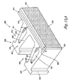
FIG. 21 is a perspective view of a mold box used to form the blocks of this invention. -
FIG. 22A is a plan view of the mold box ofFIG. 21 showing the divider plate andFIG. 22B is a plan view of the divider plate with the mold box and the blocks in phantom. - In this application, "upper" and "lower" refer to the placement of the block in a retaining wall. The lower surface faces down, that is, it is placed such that it faces the ground. In forming a retaining wall, one row of blocks is laid down, forming a course. A second course is laid on top of this by positioning the lower surface of one block on the upper surface of another block.
- The blocks of this invention may be made of a rugged, weather resistant material, such as concrete, especially if the wall is constructed outdoors. Other suitable materials include plastic, reinforced fibers, and any other materials suitable for use in molding wall blocks. The surface of the blocks may be smooth or may have a roughened appearance, such as that of natural stone. The blocks are formed in a mold and various textures can be formed on the surface, as is known in the art.
- Several embodiments are illustrated in the figures below. In one embodiment, this invention is a block comprising a front portion having two legs extending therefrom. The two legs each have a core and a back portion and the back face of each back portion is the back of the block. The cores are optional and their positions can be varied. The legs are located asymmetrically on the block. The legs have sides that define the area of the core and the leg side walls generally converge from the front toward the back.
- In another embodiment, this invention is a block similar to the block described above, except that one of the legs joins the front portion at right angles. This block is suitable for forming a corner structure.
- In another embodiment a block has one leg extending from the front face where the leg is located at one side of the front face.
- In another embodiment, a block has multiple curvilinear legs, all legs extending away from the front surface.
- The blocks of this invention may be provided with a connection means for connecting blocks in adjacent courses. The connection means may comprise pin holes and pin receiving cavities. The cavities in a second or top block accept the head of a pin placed in a pin hole of a first or bottom block. Alternatively, the bottom surface of this block may be provided with a channel configured to accept the head of a pin placed in a pin hole in an underlying block. The appearance of the front face of the block may be varied as desired.
- The advantage to the design of blocks described herein is that the blocks provide good structural stability with a maximum amount of block front face and a minimum use of material. Not only are the blocks easy to handle, but the manufacture of the blocks is efficient in its use of space and material, which can be seen, for example, by the illustration of
FIGS. 22A and22B , discussed further below. The blocks are made by forming matching pairs of blocks in a single mold designed so that one or more legs on a first block interweave or overlap with one or more legs on a second block. In this way the blocks nest together. The length of the front face of the block is generally about twice the distance from the front of the block to the back face of a leg. This has been found to maximize the volume of mold space used. Molding the blocks in this manner is also an advantage when it comes to shipping the blocks since the blocks are removed from the mold, pallatized and shipped in the same overlapping or nested configuration. This overlapping configuration takes up less space and is easier to handle than blocks molded in a conventional manner. The depth of the block (i.e., the distance from front to back surfaces) is greater than half the mold box depth. It should be understood, however, that other lengths or dimensional relationships of the blocks can be used within the scope of the invention. - This block design maximizes the area of the front face of the block while minimizing the weight of the block. As a result, the block manufacturer is able to produce more wall area per manufacturing or mold cycle and gain greater yield of wall blocks per a given volume of raw materials while at the same time manufacturing the blocks in a configuration which saves space and is easy to handle and to ship. The wall installer is able to install more face area of wall each time a block is placed and the blocks generally weigh no more or just slightly more than prior art blocks having a smaller front surface area.
- It is useful to compare the block of the present invention to prior art blocks, such as those illustrated in
FIGS. 1A to 1D above.FIG. 2 shows the presentinventive blocks 100 in a mold box. This figure can be compared directly withFIGS. 1A to 1D . The mold box illustrated is a standard size for the industry, about 18 by 24 inches (about 0,457 m by about 0,61 m), and produces a block about 8 inches (0,203 m) thick.Blocks 100 each weigh about 95 lbs (43.2 kg). The front surface (F) of the block is the dimension of the long dimension of the mold box, i.e., about 24 inches (0,61 m). Thus this block has a larger surface area (24 by 8 inches (0,61 m by 0,203 m), 192 sq in or 1.33 sq ft (0,12 m2)) than the surface area (18 by 8 inches (0,457 m by 0,203 m), 144 sq in, or 1 sq ft (0,09 m2)) of the prior art blocks shown inFIGS. 1A to 1C . This equals a 33% increase in front surface area. Yet the weight increases only about 11%, to 95 lbs from 85 lbs (43.2 to 38.6 kg), still a handleable weight. - In addition, an even greater manufacturing advantage is realized because the inventive blocks are made two at a time. Thus, one production cycle produces 2.66 sq ft (2470 sq cm) of front surface area per manufacturing cycle. This compares to the production of one sq ft (0,09 m2) for Prior Art block B1, two sq ft (0,19 m2) for Prior Art block B2, and 1.33 sq ft (0,12 m2) for Prior Art block B3. In addition, in all cases for the present block, the capacity of the mold box is maximized or at least increased substantially.
- Various embodiments of the blocks of this invention are shown in the drawings.
-
FIGS. 3 to 7 illustrateblock 100.FIGS. 8A and 8B illustrateblock 100a, which is substantially similar to block 100 except thatblock 100a has rounded corners and fewer pin holes. Similar features of these blocks will be referred to by the same numbers.Block 100 has paralleltop face 102 andbottom face 103.Front face 104 has optional bevel orchamfer 108 adjacent the top and sides of the block to provide a desirable appearance. The length offace 104 is defined by the distance betweencorners front portion 110 are twolegs Cores front portion 110. It should be noted that the shape of the cores as shown in the figures is a convenient shape for manufacturing, however, any suitable shape can be used.Legs portions -
Front face 104 andrear faces top face 102 tobottom face 103, as shown inFIG. 6 . The distance betweenfaces -
Legs void 140. Eachleg side walls top face 102 tobottom face 103. In a preferred embodiment,legs -
Side 111 ofblock 100 is shown inFIG. 5A andside 113 is shown inFIG. 5B .Side 111 comprises the side surfaces ofleg side wall 122 andback portion 124, and the side offront portion 110.Side 113, as shown inFIG. 5B , comprises the side surfaces ofleg side wall 133 andback portion 134, and the side offront portion 110. - Front portion 110 (
FIG. 3 ) includesfront face 104 and also includes pin holes 112, 114, 115, and 116 and pin receivingcavities 117 and 118 (FIG. 4A ). - It should be noted that the shape of the cores as shown in
FIGS. 3 to 8 is a convenient shape for manufacturing, however, any suitable shape can be used. The cores serve to reduce the weight of the block. When a block is manufactured, a core is tapered from top to bottom to ease stripping the block from the mold, as known to one of skill in the art. Cores are optional but may be desirable since they reduce the amount of material required to make the block, and they allow more blocks to be shipped since weight is usually a constraint on how many blocks may be shipped at one time. In addition, a lower weight block is easier for those who handle the block when constructing a wall. Further, the size and shape of the legs and voids can be varied. - Pin receiving
cavities pin holes - Pin holes 112, 114, 115 and 116 extend from the
top face 102 tobottom face 103. Four pin holes are shown, but more or fewer pin holes may be used. The holes are tapered to ease the removal of forming elements from the molded block. These pin holes are sized to receive a connecting element, such as a pin. The pin may be a shouldered pin, in which case the pin hole may be substantially the same diameter for the thickness of the block, or the pin holes may be truncated to allow a portion of a headless pin to sit above the surface of the block. Various pins are described further below. -
Block 100 is shown stacked in a running bond pattern inFIG. 7 . These blocks are configured so that the back portion of a block above rests on at least a part of the back portion of the block below. Optimally, a leg of one block is placed on the leg of an underlying block. This adds stability to a wall formed from these blocks and increases the frictional connection of the blocks. -
Block 100a inFIGS. 8A and 8B is similar to block 100, havingcurvilinear back portions legs -
FIGS. 9 and10 illustrate another embodiment of the block.Block 200 is similar toblocks FIGS. 3 to 8 , except that there are no chamfers on the front of the block. The absence of chamfered edges and corners is that the top and the bottom of the block are interchangeable, that is, ifblock 200 is flipped over, it is a mirror image of anotherblock 200. By contrast, the mirror image ofblock 100 would have to be manufactured separately if it is desired to use the block in more than one orientation when constructing a retaining wall. -
FIGS. 9 and10 show block 200 having paralleltop face 202 andbottom face 203. The length offace 204 is defined by the distance betweencorners front portion 210 are twolegs Cores front portion 210.Legs portions Front face 204 andrear faces top face 202 tobottom face 203. The distance betweenfaces -
Legs void 240. Eachleg side walls Block side walls top face 202 tobottom face 203. Pin holes 215 and 216 and pin receivingcavities -
FIGS. 11 and12 illustrate another embodiment of the block of this invention andFIG. 12 shows how the blocks form a mating pair.FIGS. 13A ,13B and14 show block 300 along withblock 200 in a course of blocks and in a wall.Block 300 is similar to block 200, but one of the legs forms right angles at the front and the back of the block. Since there are no chamfers on the front of the block, the block can be used in any orientation, i.e., the bottom and top surfaces are interchangeable. -
Block 300 has paralleltop face 302 andbottom face 303. Face 304 extends betweencorners front portion 310 are twolegs Cores front portion 310.Legs portions Front face 304 andrear faces top face 302 tobottom face 303. The distance betweenfaces -
Legs void 340. Eachleg side walls Leg side wall 322 joinsfront portion 310 andback portion 324 at right angles. Therefore,side 311 is perpendicular to thefront face 304 andback face 325.Side 313 is substantially similar toside 213 inblock 200.Side walls top face 302 tobottom face 303. Pin holes 315 and 316 and pin receivingcavities -
FIGS. 13A and13B show blocks 200 and 300 in a course of blocks for the construction of a wall.FIG. 13A showscourse 980, in which block 300 is used as the corner block in the orientation as shown inFIGS. 11 and12 .Block 300 is flipped over inFIG. 13B , which showscourse 981. During construction of a wall,courses -
FIG. 14 showswall 985 formed from these two types of blocks. -
FIGS. 15A and15B show another block embodiment, in which pin receiving cavities are absent and the front portion of the block is provided with a channel.FIGS. 15A and15B illustrate the bottom and top perspective views ofblock 400. InFIG. 15A , the block is shown in the orientation as it is manufactured, that is, with the bottom surface facing up, andFIG. 16 shows a side view of the block, with pin holes and core shown in phantom.FIG. 15B shows the block stacked together with other blocks. -
Block 400 has paralleltop face 402 andbottom face 403.Front face 404 extends betweenchamfered corners top edge 408 . Extending fromfront portion 410 are twolegs Cores front portion 410.Legs portions Front face 404 andrear faces 425 and 435 each extend fromtop face 402 tobottom face 403. The distance betweenfaces -
Legs void 440. Eachleg side walls Side 411 comprises the side surface ofside wall 422 and the side offront portion 410. Similarly,side 413 comprises the side surface ofside wall 433 and the side offront portion 410 and has a complex geometry.Side walls top face 402 tobottom face 403. -
FIG. 15B shows the top perspective view ofblock 400, illustrating that there are two pin holes.Pin holes block 400; this same plane passes through the core (e.g., core 421). It is to be noted, however, that the pin hole position may be varied as desired.Channel 444 spans the length of the block on the bottom surface near the front face.Channel 444 is configured to receive the head of a pin extending from a pin hole in a block underneath.FIG. 15B also illustrates thatback portion 424 rests onback portion 434 of an underlying block. This coincidence of back portions adds to the stability of a wall. -
FIG. 16 shows pin holes in phantom and illustrates thatpin holes FIG. 16 also showspin hole 416a opens intochannel 444. This type of pin hole is used with shouldered pins, to that the head of the pin lies within the channel. - A block according to an unclaimed example, useful for an understanding of this invention, is shown in
FIG. 17 . - The block is similar to the block embodiments described above and has correspondingly similar elements, and not every element is numbered for this block.
Block 500 has oneleg 520 extending fromfront portion 510 to backportion 524.Leg 520 comprises twoside walls core 521. The core is optional but preferred because it results in a lower weight block. - Pin holes 515 and 516 and pin receiving
cavities FIG. 17 demonstrates that a pair of blocks can be formed in the mold such that mold space is maximized. Convenient dimensions forblock 500 are those in which the front face is about 24 inches (60.1 cm) wide and 8 inches (20.3 cm) high. The depth of the front portion is about 4 inches (10.1 cm), and the depth ofleg 520 is about 8 inches (20.3 cm). -
FIG. 18 is a top view of twoblocks Blocks FIG. 18 and for clarity are shown moved apart from their position in a mold box. The formation of a mating pair results in one block having three legs (620,630, 680) and the other having four legs (720,730, 780,790). Each leg has a core (621,631, 681 and 721, 731, 781, and 791 respectively).Block 600 is provided with pin holes (615a/615b, 616a/616b) andchannel 644 that extends the length of the block on its bottom surface. Similarly, block 700 is provided with pin holes (715a/715b, 716a/716b) andchannel 744 that extends the length of the block on its bottom surface. The legs have a curvilinear shape. The legs ofblock 600 extend from the front portion in equally spaced intervals, essentially dividing the block into thirds. -
FIG. 18 illustrates that blocks having this curvilinear shape can be formed in a matching pair, thus maximizing the mold space and minimizing the amount of material needed for each block. - Regardless of the block embodiment, various pin configurations can be used, and two are shown in
FIGS. 19A and 19B . If it is desirable to use a straight pin, the pin hole should be tapered or truncated so that the pin will not slide to the bottom of the block. Thus, as shown inFIG. 19A ,pin 840 is inpin hole 116 ofblock 100. The pin hole is provided with a taper about half way through the thickness of the block. -
FIG. 19B showspin 850 havinghead 852 attached tostraight portion 854.Head 852 rests on the top surface ofblock 400.Pin hole 416b has substantially the same diameter throughout the thickness of the block. -
FIG. 20A shows a cross sectional view of a wall wherein blocks are stacked on top of each other, interlocked bypins 850, which are placed in forward pin hole 815.Head 852 fits within a channel (e.g.,channel 444 in block 400) on the bottom surface of a block above. This arrangement produces a substantially vertical wall.FIG. 20B illustrates a wall in which blocks are set back from each other by placingpin 850 in the rearward pin hole of an underlying block. A wall having positive set back is frequently desirable because of both appearance and structural stability. -
FIGS. 21 ,22A , and22B illustratemold box 900, having first and second opposing end rails 902 and first and second opposing side rails 904. The first and second end rails are spaced apart a distance d1 and the first and second side rails are spaced apart a distance d2. Distance d2 is less than distance d1. A third distance, d3, is the height of the mold box and defines the thickness of the block. The mold box sits on a bottom plate (not shown). The bottom plate, end rails and side rails together form a cavity in which blocks are molded. In order to form the blocks of this invention, the mold box is prepared by installingdivider plate 950. The divider plate thus forms first and second mold sections in the mold cavity. This plate preferably is machined from steel into the desired shape and dimensions and is bolted at either end to each side rail.FIG. 22A shows the divider plate bolted intomold box 900 with bolts 955.FIG. 22B shows the divider plate with the bolts, the mold box, and the blocks shown in phantom. - Forming elements (not shown) for the cores, pin holes, and pin receiving cavities are hung over the mold box, and a concrete mix is poured into the mold box. The box is vibrated to compact the concrete mix, which solidifies it. The blocks can then be pressed out of the mold box, and away from the divider plate and forming elements, by a stripping shoe or head that presses on the block as the bottom plate moves away. The stripping shoe is designed to pass over all the forming elements and the divider plate to facilitate removal of the block. The block, on the bottom plate, is then moved, typically by a conveyor belt, to an oven, where it is heat cured.
- Typically, the blocks are shipped in the same orientation in which they are manufactured. This is desirable because each handling step increases the cost of the block. This results in another desirable feature of the present invention. Since the blocks are manufactured in an overlapping configuration they form a compact and efficient package which is easy to handle and requires less space for shipping.
- The front surface of the block may be provided with a desired appearance or pattern by treating the surface as it is removed from the mold, just after it has been removed from the mold, or after curing. The surface appearance can be made to be smooth, corduroy, molded, fluted, ribbed, sand blasted, or fractured, as is known to one of skill in the art. Chamfers or other edge detail can be included in this molding process, as desired, or a block can be treated after curing to round the edges, by methods known to those of skill in the art. A fractured or split appearance is desirable because the surface then has the appearance of natural stone. Mechanical means can be used to treat the surface of a block after it has been cured and such is very effective in producing the appearance of natural stone. Such means are described in commonly assigned, co-pending application
U.S. Application Publication No. 2003-0214069 (Serial No.10/150,484, filed May 17, 2002 - Though the blocks illustrated in the Figures may have any desired dimension, block 100, for example (as in
FIGS. 3 to 8 ) typically has a thickness (i.e., the distance betweensurfaces 102 and 103) of about 8 inches (20.3 cm) and a length (i.e., the distance from corner 20a to corner 21a) of about 24 inches (60.1 cm). The length is determined by distance d1 of the mold box. - For those blocks described above having a length of about 24 inches (60.1 cm), a depth (i.e., from the front surface to a back surface) of about 12 inches (30.5 cm), and a thickness of about 8 inches (20.3 cm), the weight is about 95 pounds (43.2 kg). This translates to about 60 pounds (27.3 kg) per square foot (0,09 m2) of front face surface area. This is a convenient weight to use when positioning the blocks in a retaining wall and compares favorably to the weight of Prior Art blocks in terms of handling. Thus the blocks offer an advantage over the Prior Art blocks in terms of their higher front surface area per unit weight.
- The blocks of this invention are efficient to use in constructing walls because the relatively larger face size, compared to the face size of prior art blocks, results in about one third more area when building a wall.
- Although particular embodiments have been disclosed herein in detail, this has been done for purposes of illustration only, and is not intended to be limiting with respect to the scope of the claims. In particular, it is contemplated that various substitutions, alterations and modifications may be made to the invention without departing from the scope of the invention as defined by the claims. For instance, the choice of materials or variations in the shape or angles at which some of the surfaces intersect are believed to be a matter of routine for a person of ordinary skill in the art with knowledge of the embodiments disclosed herein.
Claims (14)
- A mold box (900) for making a matching pair of first and second wall blocks comprising:first and second opposed end rails (902) and first and second opposed side rails, the end rails and side rails together forming a mold cavity, the first and second end rails being spaced apart a distance d1, the first and second side rails being spaced apart a distance d2 which is less than distance d1; anda divider plate (950) having a first end connected to the first end rail and a second end connected to the second end rail, the divider plate dividing the mold cavity into a first mold section for forming the first block and a second mold section for forming the second block, the first mold section being configured such that a front face of the first block is formed adjacent the first side rail, the second mold section being configured such that a front face of the second block is formed adjacent the second side rail, the divider plate being shaped in a non-planar configuration such that a maximum first block depth measured between the first side rail and the divider plate along a line generally perpendicular to the first side rail is greater than d2/2 and a maximum second block depth measured between the second side rail and the divider plate along a line generally perpendicular to the second side rail is greater than d2/2,the divider plate having a first mold surface and a second mold surface, a rear face of the first block being formed adjacent the first mold surface and a rear face of the second block being formed adjacent the second mold surface, the divider plate being configured such that the rear faces of the first and second blocks overlap when they are formed in the mold cavity,the divider plate being configured such that the first and second blocks have two legs extending from a front portion of each block, andthe front faces of the first and second blocks each having a length approximately equal to d1,characterized in that the divider plate is configured such that one leg on the first block interweaves with the two legs on the second block, and vice versa so that the blocks nest together when the first and second blocks are in the mold box.
- The mold box (900) of claim 1 wherein the legs are located asymmetrically on the first and second blocks.
- The mold box (900) of one of claims 1 and 2 wherein the length of the front face of the first block is about twice the distance from the front face of the first block to back faces of the legs of the first block.
- The mold box (900) of claim 1 wherein distance d1 is about 61 cm and distance d2 is about 45.7 cm.
- The mold box (900) of claim 4 wherein the mold box has a thickness defmed by a distance d3, wherein distance d3 is less than distance d2.
- The mold box (900) of claim 5 wherein distance d3 is 20.3 cm.
- A method of making wall blocks comprising:(i) providing a mold box (900) of claim 1;(ii) filling the first and second mold sections with a desired block material; and(iii) removing the block material from the first mold section to form the first block and from the second mold section to form the second block.
- The method of claim 7 wherein the legs are located asymmetrically on the first and second blocks.
- The method of one of claims 7 and 8 wherein the length of the front face of the first block is about twice the distance from the front face of the first block to back faces of the legs of the first block.
- The method of claim 7 wherein distance d1 is about 61 cm and distance d2 is about 45.7 cm.
- The method of claim 10 wherein the mold box has a thickness defined by a distance d3, wherein distance d3 is less than distance d2.
- The method of claim 11 wherein distance d3 is 20.3 cm.
- The method of claim 7 further comprising providing a bottom plate and placing the mold box on the bottom plate before filling the first and second mold sections with the desired block material.
- The method of claim 13 wherein the block material is removed by pressing the blocks out of the mold box as the bottom plate moves away from the mold box.
Applications Claiming Priority (3)
| Application Number | Priority Date | Filing Date | Title |
|---|---|---|---|
| US29/186,712 USD501935S1 (en) | 2003-07-21 | 2003-07-21 | Wall block |
| US10/754,454 US7780141B2 (en) | 2003-07-21 | 2004-01-09 | Mold box for making first and second wall blocks |
| PCT/US2004/023256 WO2005009707A1 (en) | 2003-07-21 | 2004-07-19 | Method of making wall block |
Publications (2)
| Publication Number | Publication Date |
|---|---|
| EP1648669A1 EP1648669A1 (en) | 2006-04-26 |
| EP1648669B1 true EP1648669B1 (en) | 2014-03-26 |
Family
ID=34107187
Family Applications (1)
| Application Number | Title | Priority Date | Filing Date |
|---|---|---|---|
| EP04778662.9A Expired - Lifetime EP1648669B1 (en) | 2003-07-21 | 2004-07-19 | Mould for making wall blocks and method of making wall blocks using such mould |
Country Status (16)
| Country | Link |
|---|---|
| US (4) | USD501935S1 (en) |
| EP (1) | EP1648669B1 (en) |
| JP (1) | JP4700609B2 (en) |
| KR (1) | KR101141611B1 (en) |
| CN (1) | CN1938134A (en) |
| AU (1) | AU2004259740B2 (en) |
| CA (2) | CA2533399C (en) |
| CR (1) | CR8241A (en) |
| EG (1) | EG25299A (en) |
| IL (1) | IL173263A0 (en) |
| MX (1) | MXPA06000821A (en) |
| NO (1) | NO20060738L (en) |
| NZ (1) | NZ545327A (en) |
| RU (1) | RU2360795C2 (en) |
| SG (1) | SG122974A1 (en) |
| WO (1) | WO2005009707A1 (en) |
Families Citing this family (85)
| Publication number | Priority date | Publication date | Assignee | Title |
|---|---|---|---|---|
| USD501935S1 (en) * | 2003-07-21 | 2005-02-15 | Keystone Retaining Wall Systems, Inc. | Wall block |
| US7497646B2 (en) * | 2004-11-12 | 2009-03-03 | Mortarless Technologies Llc | Extended width retaining wall block |
| EP1834054A2 (en) | 2004-11-12 | 2007-09-19 | Mortarless Technologies LLC. | Extended width retaining wall block |
| MX2007005700A (en) * | 2004-11-12 | 2007-07-20 | Mortarless Technologies Llc | Extended width retaining wall block. |
| CA2492250C (en) | 2005-01-11 | 2013-10-08 | Novabrik International Inc. | A molding equipment and method to manufacture stackable inter-engaging bricks, blocks, stones and the like with a smooth or embossed face |
| US7351015B2 (en) * | 2005-10-11 | 2008-04-01 | Mortarless Technologies, Llc | Invertible retaining wall block |
| USD555808S1 (en) | 2005-10-11 | 2007-11-20 | Mortarless Technologies, Llc | Engagement projection of a retaining wall block |
| USD548365S1 (en) | 2005-10-11 | 2007-08-07 | Mortarless Technologies, Llc | Portion of a retaining wall block |
| USD547881S1 (en) | 2005-10-11 | 2007-07-31 | Mortarless Technologies, Llc | Portion of a retaining wall block |
| USD546972S1 (en) | 2005-10-11 | 2007-07-17 | Mortarless Technologies, Llc | Portion of a retaining wall block |
| USD548367S1 (en) | 2005-11-12 | 2007-08-07 | Mortarless Technologies, Llc | Portion of a retaining wall block |
| USD548366S1 (en) | 2005-11-12 | 2007-08-07 | Mortarless Technologies, Llc | Portion of a retaining wall block |
| USD539436S1 (en) * | 2006-04-11 | 2007-03-27 | Softsplit Technology, Inc. | Block face |
| USD539437S1 (en) * | 2006-04-11 | 2007-03-27 | Softsplit Technology, Inc. | Block face |
| US7963727B1 (en) | 2006-09-12 | 2011-06-21 | E. Dillon & Company | Retaining wall block and retaining wall comprised of retaining wall blocks |
| US20100132298A1 (en) * | 2007-10-03 | 2010-06-03 | Sci Materials | Retaining wall block and system |
| US20090090077A1 (en) * | 2007-10-03 | 2009-04-09 | Sci Materials | Retaining wall block and system |
| USD587382S1 (en) * | 2007-10-15 | 2009-02-24 | E. Dillon & Company | Retaining wall block |
| CA2700226C (en) | 2007-11-08 | 2018-02-27 | Keystone Retaining Wall Systems, Inc. | Wall block with weight bearing pads and method of producing wall blocks |
| WO2009097524A1 (en) | 2008-01-30 | 2009-08-06 | Keystone Retaining Wall Systems, Inc. | Block system with corner block and method of manufacturing a block |
| USD602171S1 (en) * | 2008-02-05 | 2009-10-13 | Harold Rodebaugh | Concrete block |
| US8015772B2 (en) * | 2008-08-19 | 2011-09-13 | David Jensen | Two part interlocking unit block wall building system |
| USD610711S1 (en) * | 2008-11-07 | 2010-02-23 | Keystone Retaining Wall Systems, Inc. | Wall block body |
| USD610710S1 (en) | 2008-11-07 | 2010-02-23 | Keystone Retaining Wall Systems, Inc. | Wall block |
| USD609966S1 (en) * | 2009-03-04 | 2010-02-16 | Whirlpool Corporation | Kickplate |
| US20100303555A1 (en) * | 2009-06-02 | 2010-12-02 | Allan John Herse | Concrete block for wall, walls having such blocks, and methods |
| USD663329S1 (en) | 2009-06-19 | 2012-07-10 | Westblock Systems, Inc. | Concrete block mold |
| USD611166S1 (en) * | 2009-06-19 | 2010-03-02 | Westblock Systems, Inc. | Retaining block |
| USD610712S1 (en) | 2009-06-19 | 2010-02-23 | Westblock Systems, Inc. | Portion of retaining block |
| USD611167S1 (en) * | 2009-06-19 | 2010-03-02 | Westblock Systems, Inc. | Portion of retaining block |
| USD611165S1 (en) * | 2009-06-19 | 2010-03-02 | Westblock Systems, Inc. | Retaining block |
| USD615668S1 (en) | 2009-06-19 | 2010-05-11 | Westblock Systems, Inc. | Portion of a retaining block |
| USD611168S1 (en) * | 2009-06-19 | 2010-03-02 | Westblock Systems, Inc. | Portion of retaining block |
| USD610713S1 (en) * | 2009-06-19 | 2010-02-23 | Westblock Systems, Inc. | Retaining block |
| US9796110B2 (en) * | 2009-07-30 | 2017-10-24 | Anchor Wall Systems, Inc. | Method for making dry cast block with burnished surface |
| NZ601997A (en) * | 2010-03-02 | 2013-12-20 | Keystone Retaining Wall System | Retaining wall block system |
| AU2011223600B2 (en) * | 2010-03-04 | 2016-02-25 | Keystone Retaining Wall Systems, Inc. | Retaining wall |
| USD663858S1 (en) | 2010-07-20 | 2012-07-17 | Keystone Retaining Wall Systems Llc | Landscaping block |
| US8876438B2 (en) * | 2010-07-30 | 2014-11-04 | Redi-Rock International, Llc | Process for casting concrete wall blocks for use with geogrid |
| US8734060B1 (en) | 2011-02-17 | 2014-05-27 | E. Dillon & Company | Double-wall structure comprised of interconnected dry-stacked wall blocks |
| USD653356S1 (en) | 2011-02-28 | 2012-01-31 | Keystone Retaining Wall Systems, Inc. | Landscaping block |
| USD647633S1 (en) | 2011-02-28 | 2011-10-25 | Keystone Retaining Wall Systems, Inc. | Landscaping block |
| USD647632S1 (en) | 2011-02-28 | 2011-10-25 | Keystone Retaining Wall Systems, Inc. | Landscaping block |
| USD647218S1 (en) | 2011-02-28 | 2011-10-18 | Keystone Retaining Wall Systems, Inc. | Landscaping block |
| USD647219S1 (en) | 2011-02-28 | 2011-10-18 | Keystone Retaining Wall Systems, Inc. | Landscaping block |
| USD656627S1 (en) | 2011-03-01 | 2012-03-27 | Keystone Retaining Wall Systems, Inc. | Landscaping block |
| USD656625S1 (en) | 2011-03-01 | 2012-03-27 | Keystone Retaining Wall Systems, Inc. | Landscaping block |
| USD656243S1 (en) | 2011-03-01 | 2012-03-20 | Keystone Retaining Wall Systems, Inc. | Landscaping block |
| USD656244S1 (en) | 2011-03-01 | 2012-03-20 | Keystone Retaining Wall Systems, Inc. | Landscaping block |
| USD656626S1 (en) | 2011-03-01 | 2012-03-27 | Keystone Retaining Wall Systems, Inc. | Landscaping block |
| USD656242S1 (en) | 2011-03-01 | 2012-03-20 | Keystone Retaining Wall Systems, Inc. | Landscaping block |
| USD667140S1 (en) * | 2011-06-28 | 2012-09-11 | Keystone Retaining Wall Systems Llc | Landscaping block |
| USD672886S1 (en) * | 2011-06-28 | 2012-12-18 | Keystone Retaining Wall Systems Llc | Landscaping block |
| USD667139S1 (en) * | 2011-06-28 | 2012-09-11 | Keystone Retaining Wall Systems Llc | Landscaping block |
| USD667566S1 (en) | 2011-06-28 | 2012-09-18 | Keystone Retaining Wall Systems Llc | Landscaping block |
| USD666741S1 (en) | 2011-06-28 | 2012-09-04 | Keystone Retaining Wall Systems Llc | Landscaping block |
| USD672887S1 (en) * | 2011-06-28 | 2012-12-18 | Keystone Retaining Wall Systems Llc | Landscaping block |
| USD666740S1 (en) | 2011-06-28 | 2012-09-04 | Keystone Retaining Wall Systems Llc | Landscaping block |
| US9145676B2 (en) * | 2011-11-09 | 2015-09-29 | E.P. Henry Corporation | Masonry block with taper |
| USD689203S1 (en) | 2012-03-29 | 2013-09-03 | Keystone Retaining Wall Systems Llc | Landscaping block |
| USD694914S1 (en) | 2012-03-29 | 2013-12-03 | Keystone Retaining Wall Systems Llc | Landscaping block |
| USD689204S1 (en) | 2012-03-29 | 2013-09-03 | Keystone Retaining Wall Systems Llc | Landscaping block |
| USD688812S1 (en) | 2012-04-19 | 2013-08-27 | Keystone Retaining Wall Systems Llc | Landscaping block |
| USD688813S1 (en) | 2012-04-19 | 2013-08-27 | Keystone Retaining Wall Systems Llc | Landscaping block |
| USD688816S1 (en) | 2012-04-19 | 2013-08-27 | Keystone Retaining Wall Systems Llc | Landscaping block |
| USD688814S1 (en) | 2012-04-19 | 2013-08-27 | Keystone Retaining Wall Systems Llc | Landscaping block |
| NZ701516A (en) | 2012-04-19 | 2016-09-30 | Keystone Retaining Wall System | Wall block and wall block system |
| USD688815S1 (en) | 2012-04-19 | 2013-08-27 | Keystone Retaining Wall Systems Llc | Landscaping block |
| CA2900396A1 (en) | 2013-02-28 | 2014-09-04 | Keystone Retaining Wall Systems Llc | Patio block, patio system and method of making a patio |
| USD701326S1 (en) | 2013-02-28 | 2014-03-18 | Keystone Retaining Wall Systems Llc | Landscaping block |
| USD701325S1 (en) | 2013-02-28 | 2014-03-18 | Keystone Retaining Wall Systems Llc | Landscaping block |
| USD700716S1 (en) * | 2013-03-15 | 2014-03-04 | Pacific Coast Building Products, Inc. | Wall block |
| EP2999830B1 (en) * | 2013-05-15 | 2017-06-14 | Anchor Wall Systems, Inc. | Multi-use building block |
| AU2017217413B2 (en) * | 2016-02-08 | 2022-08-18 | Tensar International Corporation | Multi-oriented segmental wall blocks, soil reinforcing system, and methods |
| US11149402B2 (en) | 2016-03-02 | 2021-10-19 | Evergreen Walls, Inc. | Building elements for making retaining walls, and systems and methods of using same |
| CA2959421A1 (en) * | 2016-03-02 | 2017-09-02 | Evergreen Walls, Inc. | Building element for making retaining wall using filling material |
| US10094109B2 (en) * | 2017-02-03 | 2018-10-09 | Gouda-Torgerson Building Systems Llc | Construction blocks |
| US10648151B2 (en) | 2017-04-05 | 2020-05-12 | Earth Wall Products, Llc | Retaining wall block mold and method |
| US10316485B1 (en) * | 2018-07-17 | 2019-06-11 | Pacific Coast Building Products, Inc. | Retaining wall block |
| US11603665B2 (en) | 2018-12-18 | 2023-03-14 | Kuan-Chih Jang | Hollow brick with holding ribs |
| TWI686530B (en) * | 2018-12-18 | 2020-03-01 | 詹廣志 | Roof ventilation and temperature adjustment combined device |
| TWI755578B (en) * | 2018-12-18 | 2022-02-21 | 詹廣志 | Hollow bricks for roof temperature regulation |
| EP4305246A4 (en) * | 2021-03-09 | 2025-01-29 | Felix P. Jaecklin | CONSTRUCTION ELEMENTS FOR THE MANUFACTURE OF RETAINING WALLS AND SYSTEMS AND METHODS USING THEM |
| USD1041034S1 (en) * | 2021-04-28 | 2024-09-03 | Keystone Retaining Wall Systems, Llc | Landscaping block |
| USD1036705S1 (en) * | 2021-04-28 | 2024-07-23 | Keystone Retaining Wall Systems, Llc | Landscaping block |
Citations (1)
| Publication number | Priority date | Publication date | Assignee | Title |
|---|---|---|---|---|
| US895614A (en) * | 1907-12-23 | 1908-08-11 | Emil Buscher | Block-molding machine. |
Family Cites Families (76)
| Publication number | Priority date | Publication date | Assignee | Title |
|---|---|---|---|---|
| US751346A (en) * | 1904-02-02 | Building-tile | ||
| US760803A (en) * | 1903-01-21 | 1904-05-24 | John P Oosting | Mold for construction of solid brick or stone. |
| US819229A (en) | 1905-04-11 | 1906-05-01 | Theodore G Johnson | Adjustable mold. |
| US799709A (en) * | 1905-04-27 | 1905-09-19 | Charles W Bradley | Molding-machine. |
| US955230A (en) * | 1908-10-13 | 1910-04-19 | Hector Van Caeyseele | Building blocks and wall. |
| US1045411A (en) * | 1912-03-02 | 1912-11-26 | Luther T Kenny | Molding-machine. |
| US1219127A (en) | 1916-02-28 | 1917-03-13 | George Miller Marshall | Mold for building-blocks. |
| US1355580A (en) * | 1918-02-04 | 1920-10-12 | Thomas C Tyson | System of composition unit construction |
| US1526730A (en) * | 1923-09-18 | 1925-02-17 | Anthony M Zottoll | Building block and wall construction |
| US1594387A (en) * | 1924-02-25 | 1926-08-03 | Charles L Stubbs | Tile |
| US1652180A (en) * | 1925-08-20 | 1927-12-13 | Edward S Nicholas | Mold for concrete building blocks |
| US1631901A (en) * | 1926-09-11 | 1927-06-07 | William A Threadgill | Concrete-block mold |
| US1690462A (en) * | 1927-02-15 | 1928-11-06 | Kadow Foundation Inc | Mold for concrete blocks |
| US1647436A (en) * | 1927-04-04 | 1927-11-01 | Charles A Covey | Cement-block mold |
| US2011531A (en) * | 1931-08-28 | 1935-08-13 | Highway Form Company | Tile or block |
| US2121450A (en) | 1936-02-28 | 1938-06-21 | Johannes T Sentrop | Mold structure |
| US2324039A (en) * | 1941-05-31 | 1943-07-13 | Charles W Stone | Prefabricated construction unit |
| US3017683A (en) * | 1959-05-28 | 1962-01-23 | Carl W Huch | Apparatus for producing wall block forms |
| US3013683A (en) | 1959-06-25 | 1961-12-19 | Harris Foster | Jacks for tag-along trailers |
| US3694128A (en) | 1970-05-06 | 1972-09-26 | Benjamin F Foxen | Block molding apparatus |
| JPS4917857U (en) | 1972-05-22 | 1974-02-15 | ||
| US4098865A (en) | 1976-01-26 | 1978-07-04 | Hanover Prest-Paving Co. | Methods of making paving block |
| US4063866A (en) | 1976-05-03 | 1977-12-20 | Lurbiecki Manfred A | Concrete block forming and facing machine |
| US4023767A (en) | 1976-06-15 | 1977-05-17 | Fontana Joseph R | Mold box and mold head |
| FR2406700A1 (en) | 1977-10-21 | 1979-05-18 | Sabla Sa | PREFABRICATED ELEMENT OF CONSTRUCTION FOR THE ERECTION OF WALLS, ESPECIALLY OF SUPPORT |
| US4218206A (en) | 1978-10-02 | 1980-08-19 | Mullins Wayne L | Mold box apparatus |
| US4335549A (en) | 1980-12-01 | 1982-06-22 | Designer Blocks, Inc. | Method, building structure and side-split block therefore |
| SU939214A1 (en) | 1980-12-05 | 1982-06-30 | за витель Р. А. Кагиров | Mould for making concrete and ferroconcrete products |
| JPS57193631A (en) | 1981-05-22 | 1982-11-29 | Terada Sangyo Kk | L-shaped concrete block to be integrally combined with ground and construction of retaining wall by block thereof |
| US4426176A (en) | 1981-08-10 | 1984-01-17 | Tokuyama Soda Co., Ltd. | L-Shaped concrete block and method for constructing a retaining wall by such L-shaped concrete blocks |
| JPS5928821Y2 (en) | 1981-12-23 | 1984-08-20 | 茂 田中 | Formwork for manufacturing inverted Y-shaped retaining walls |
| US4592678A (en) | 1984-05-14 | 1986-06-03 | Mcninch Jr Edwin K | Modular block retaining wall |
| CA1222149A (en) | 1984-07-19 | 1987-05-26 | Rodney J.P. Dietrich | Self-leveling block and method of use |
| US4909717A (en) | 1985-02-04 | 1990-03-20 | National Concrete Masonry Association | Biaxial concrete masonry casting apparatus |
| US5108281A (en) | 1985-02-04 | 1992-04-28 | National Concrete Masonry Association | Biaxial concrete masonry casting apparatus |
| US4684294A (en) | 1986-01-15 | 1987-08-04 | Neill Raymond J O | Retaining wall construction element |
| US4704832A (en) * | 1986-05-20 | 1987-11-10 | Theodor Vassiliadis | Building system |
| USRE34314E (en) | 1986-09-15 | 1993-07-20 | Keystone Retaining Wall Systems, Inc. | Block wall |
| US4802320A (en) | 1986-09-15 | 1989-02-07 | Keystone Retaining Wall Systems, Inc. | Retaining wall block |
| USD296365S (en) * | 1986-09-18 | 1988-06-21 | Keystone Retaining Wall Systems, Inc. | Construction block |
| EP0282679B1 (en) * | 1987-03-20 | 1991-01-16 | Rolf Scheiwiller | Set of elements for composite constructions |
| US4802836A (en) | 1987-07-13 | 1989-02-07 | Gilles Whissell | Compaction device for concrete block molding machine |
| US4884921A (en) | 1988-09-15 | 1989-12-05 | Fomico International, Inc. | Retaining wall module having face panel and T-stem with means for receiving transverse stabilizing web |
| US5062610A (en) | 1989-09-28 | 1991-11-05 | Block Systems Inc. | Composite masonry block mold for use in block molding machines |
| US5163261A (en) | 1990-03-21 | 1992-11-17 | Neill Raymond J O | Retaining wall and soil reinforcement subsystems and construction elements for use therein |
| US5135384A (en) | 1990-07-06 | 1992-08-04 | Seagren Industries, Inc. | Molding machine |
| DE4101593A1 (en) | 1991-01-21 | 1992-07-23 | Siegfried Gebhart | DEVICE FOR PRODUCING STONES |
| SG46457A1 (en) * | 1992-10-06 | 1998-02-20 | Anchor Wall Syst | Composite masonry block |
| JP2706216B2 (en) * | 1993-10-15 | 1998-01-28 | 有限会社マス構造企画 | Retaining wall block and retaining wall construction |
| US5484236A (en) | 1993-10-25 | 1996-01-16 | Allan Block Corporation | Method of forming concrete retaining wall block |
| US5551809A (en) | 1994-08-30 | 1996-09-03 | Keystone Retaining Wall Systems, Inc. | Embankment wall construction and method and block construction for making the same |
| US5598679A (en) | 1994-12-20 | 1997-02-04 | Orton; Michael V. | Cast concrete block and method of making same |
| US5913790A (en) * | 1995-06-07 | 1999-06-22 | Keystone Retaining Wall Systems, Inc. | Plantable retaining wall block |
| US5865005A (en) | 1997-08-06 | 1999-02-02 | Cataldo; Michael A. | Prefabricated concrete retaining wall |
| US5930964A (en) | 1998-02-04 | 1999-08-03 | Boehning; John W. | Composite lightweight building element and methods of making and using same |
| US6106264A (en) | 1998-06-25 | 2000-08-22 | Newtec Building Products Inc. | Apparatus for molding blocks |
| US6113379A (en) * | 1998-07-02 | 2000-09-05 | Anchor Wall Systems, Inc. | Process for producing masonry block with roughened surface |
| US6322742B1 (en) | 1998-07-06 | 2001-11-27 | Allan Block Corporation | Method of producing stackable concrete blocks |
| AUPP647298A0 (en) | 1998-10-13 | 1998-11-05 | Keystone Retaining Wall Systems, Inc. | Retaining wall block |
| US6557818B2 (en) | 1999-09-30 | 2003-05-06 | Redi-Rock International, Llc | Form for manufacturing concrete retaining wall blocks |
| US6854702B2 (en) | 1999-09-30 | 2005-02-15 | Redi-Rock International, Llc | Form for manufacturing concrete blocks for freestanding walls |
| DE10107531A1 (en) | 2000-12-23 | 2002-06-27 | Nuedling Franz C Basaltwerk | Molded brick producing process involves producing adjacent bricks with axes in longitudinal direction deviating from that of row |
| US6620364B2 (en) | 2001-02-20 | 2003-09-16 | Recon Wall Systems, Inc. | Block forming apparatus and method |
| US6615561B2 (en) | 2001-06-07 | 2003-09-09 | Keystone Retaining Wall Systems, Inc. | Retaining wall block |
| US7140867B2 (en) | 2002-01-04 | 2006-11-28 | Anchor Wall Systems, Inc. | Mold for making a masonry block |
| US6773642B1 (en) | 2002-01-04 | 2004-08-10 | Michael James Wardell | Method of forming a concrete retaining wall block in a front face up position |
| US7208112B2 (en) | 2002-01-04 | 2007-04-24 | Anchor Wall Systems, Inc. | Concrete block and method of making same |
| US6803002B2 (en) | 2002-05-17 | 2004-10-12 | Keystone Retaining Wall Systems, Inc. | Method for making and treating wall blocks |
| US6978580B1 (en) | 2002-11-08 | 2005-12-27 | Ryan Clark | Solid core concrete block and method of making a concrete block retaining wall |
| USD501935S1 (en) * | 2003-07-21 | 2005-02-15 | Keystone Retaining Wall Systems, Inc. | Wall block |
| US7156645B2 (en) | 2003-07-29 | 2007-01-02 | Ness Inventions, Inc. | Concrete block mold with moveable liner |
| US7175414B2 (en) | 2003-07-29 | 2007-02-13 | Ness Inventions, Inc. | Block mold having moveable liner |
| US7261548B2 (en) | 2003-07-29 | 2007-08-28 | Haberman Machine | Concrete block mold with moveable liner |
| DE102004007070B3 (en) | 2004-02-13 | 2005-09-29 | Hess Maschinenfabrik Gmbh & Co. Kg | Concrete block machine with a movable part via a linear drive |
| US7090439B1 (en) | 2005-02-09 | 2006-08-15 | The Neel Company | Retaining wall construction element for railway installations |
| US7179077B2 (en) | 2005-02-17 | 2007-02-20 | Donald P. Chennells | Concrete block press |
-
2003
- 2003-07-21 US US29/186,712 patent/USD501935S1/en not_active Expired - Lifetime
-
2004
- 2004-01-09 US US10/754,454 patent/US7780141B2/en not_active Expired - Fee Related
- 2004-07-19 NZ NZ545327A patent/NZ545327A/en not_active IP Right Cessation
- 2004-07-19 KR KR1020067001443A patent/KR101141611B1/en not_active Expired - Fee Related
- 2004-07-19 EP EP04778662.9A patent/EP1648669B1/en not_active Expired - Lifetime
- 2004-07-19 MX MXPA06000821A patent/MXPA06000821A/en active IP Right Grant
- 2004-07-19 CA CA2533399A patent/CA2533399C/en not_active Expired - Lifetime
- 2004-07-19 AU AU2004259740A patent/AU2004259740B2/en not_active Expired
- 2004-07-19 RU RU2006105197/03A patent/RU2360795C2/en not_active IP Right Cessation
- 2004-07-19 SG SG200603437A patent/SG122974A1/en unknown
- 2004-07-19 WO PCT/US2004/023256 patent/WO2005009707A1/en not_active Ceased
- 2004-07-19 CN CNA2004800243898A patent/CN1938134A/en active Pending
- 2004-07-19 JP JP2006521179A patent/JP4700609B2/en not_active Expired - Fee Related
- 2004-07-19 CA CA2692333A patent/CA2692333C/en not_active Expired - Lifetime
-
2006
- 2006-01-19 IL IL173263A patent/IL173263A0/en not_active IP Right Cessation
- 2006-01-21 EG EGNA2006000062 patent/EG25299A/en active
- 2006-02-15 NO NO20060738A patent/NO20060738L/en not_active Application Discontinuation
- 2006-02-21 CR CR8241A patent/CR8241A/en not_active Application Discontinuation
-
2010
- 2010-07-19 US US12/839,028 patent/US8132988B2/en not_active Expired - Fee Related
-
2012
- 2012-02-07 US US13/368,005 patent/US20120131873A1/en not_active Abandoned
Patent Citations (1)
| Publication number | Priority date | Publication date | Assignee | Title |
|---|---|---|---|---|
| US895614A (en) * | 1907-12-23 | 1908-08-11 | Emil Buscher | Block-molding machine. |
Also Published As
| Publication number | Publication date |
|---|---|
| EG25299A (en) | 2011-12-07 |
| CA2533399C (en) | 2011-01-11 |
| CR8241A (en) | 2008-10-08 |
| IL173263A0 (en) | 2006-06-11 |
| US7780141B2 (en) | 2010-08-24 |
| AU2004259740B2 (en) | 2009-06-11 |
| JP4700609B2 (en) | 2011-06-15 |
| KR20060058689A (en) | 2006-05-30 |
| CA2692333A1 (en) | 2005-02-03 |
| US20050016106A1 (en) | 2005-01-27 |
| SG122974A1 (en) | 2006-06-29 |
| NZ545327A (en) | 2009-07-31 |
| US20100281809A1 (en) | 2010-11-11 |
| RU2006105197A (en) | 2006-07-10 |
| JP2006528099A (en) | 2006-12-14 |
| NO20060738L (en) | 2006-04-07 |
| RU2360795C2 (en) | 2009-07-10 |
| US20120131873A1 (en) | 2012-05-31 |
| CA2533399A1 (en) | 2005-02-03 |
| US8132988B2 (en) | 2012-03-13 |
| CA2692333C (en) | 2012-09-25 |
| MXPA06000821A (en) | 2006-04-07 |
| KR101141611B1 (en) | 2012-05-17 |
| EP1648669A1 (en) | 2006-04-26 |
| CN1938134A (en) | 2007-03-28 |
| WO2005009707A1 (en) | 2005-02-03 |
| USD501935S1 (en) | 2005-02-15 |
| AU2004259740A1 (en) | 2005-02-03 |
Similar Documents
| Publication | Publication Date | Title |
|---|---|---|
| EP1648669B1 (en) | Mould for making wall blocks and method of making wall blocks using such mould | |
| CA2700908C (en) | Retaining wall block | |
| US7971407B2 (en) | Wall block and wall block system for constructing walls | |
| US20090188196A1 (en) | Block system with corner block and method of manufacturing a block | |
| US8464481B2 (en) | Segmental retaining wall corner block | |
| CA2872256C (en) | Wall block and wall block system | |
| US9038346B1 (en) | Segmental retaining wall corner block and wall corner comprised of corner blocks | |
| MXPA06012167A (en) | Wall block system. | |
| CA2324037C (en) | Stair block for use in landscaping and method for manufacture thereof | |
| EP1838933B1 (en) | A moulding equipment and method to manufacture stackable inter-engaging bricks with a smooth or embossed face | |
| ZA200600750B (en) | Method of making wall block | |
| HK1104012A (en) | Method of making wall block | |
| ES2457045T3 (en) | Mold for manufacturing wall or wall blocks and method of manufacturing wall or wall blocks using said method |
Legal Events
| Date | Code | Title | Description |
|---|---|---|---|
| PUAI | Public reference made under article 153(3) epc to a published international application that has entered the european phase |
Free format text: ORIGINAL CODE: 0009012 |
|
| 17P | Request for examination filed |
Effective date: 20060209 |
|
| AK | Designated contracting states |
Kind code of ref document: A1 Designated state(s): AT BE BG CH CY CZ DE DK EE ES FI FR GB GR HU IE IT LI LU MC NL PL PT RO SE SI SK TR |
|
| DAX | Request for extension of the european patent (deleted) | ||
| 17Q | First examination report despatched |
Effective date: 20080714 |
|
| GRAP | Despatch of communication of intention to grant a patent |
Free format text: ORIGINAL CODE: EPIDOSNIGR1 |
|
| INTG | Intention to grant announced |
Effective date: 20131011 |
|
| GRAS | Grant fee paid |
Free format text: ORIGINAL CODE: EPIDOSNIGR3 |
|
| GRAA | (expected) grant |
Free format text: ORIGINAL CODE: 0009210 |
|
| RAP1 | Party data changed (applicant data changed or rights of an application transferred) |
Owner name: KEYSTONE RETAINING WALL SYSTEMS LLC |
|
| AK | Designated contracting states |
Kind code of ref document: B1 Designated state(s): AT BE BG CH CY CZ DE DK EE ES FI FR GB GR HU IE IT LI LU MC NL PL PT RO SE SI SK TR |
|
| REG | Reference to a national code |
Ref country code: GB Ref legal event code: FG4D |
|
| REG | Reference to a national code |
Ref country code: CH Ref legal event code: EP |
|
| REG | Reference to a national code |
Ref country code: AT Ref legal event code: REF Ref document number: 658711 Country of ref document: AT Kind code of ref document: T Effective date: 20140415 |
|
| REG | Reference to a national code |
Ref country code: ES Ref legal event code: FG2A Ref document number: 2457045 Country of ref document: ES Kind code of ref document: T3 Effective date: 20140424 |
|
| REG | Reference to a national code |
Ref country code: IE Ref legal event code: FG4D |
|
| REG | Reference to a national code |
Ref country code: DE Ref legal event code: R096 Ref document number: 602004044694 Country of ref document: DE Effective date: 20140508 |
|
| REG | Reference to a national code |
Ref country code: SE Ref legal event code: TRGR |
|
| REG | Reference to a national code |
Ref country code: AT Ref legal event code: MK05 Ref document number: 658711 Country of ref document: AT Kind code of ref document: T Effective date: 20140326 |
|
| REG | Reference to a national code |
Ref country code: NL Ref legal event code: VDEP Effective date: 20140326 |
|
| PG25 | Lapsed in a contracting state [announced via postgrant information from national office to epo] |
Ref country code: FI Free format text: LAPSE BECAUSE OF FAILURE TO SUBMIT A TRANSLATION OF THE DESCRIPTION OR TO PAY THE FEE WITHIN THE PRESCRIBED TIME-LIMIT Effective date: 20140326 |
|
| PG25 | Lapsed in a contracting state [announced via postgrant information from national office to epo] |
Ref country code: BE Free format text: LAPSE BECAUSE OF FAILURE TO SUBMIT A TRANSLATION OF THE DESCRIPTION OR TO PAY THE FEE WITHIN THE PRESCRIBED TIME-LIMIT Effective date: 20140326 Ref country code: EE Free format text: LAPSE BECAUSE OF FAILURE TO SUBMIT A TRANSLATION OF THE DESCRIPTION OR TO PAY THE FEE WITHIN THE PRESCRIBED TIME-LIMIT Effective date: 20140326 Ref country code: CY Free format text: LAPSE BECAUSE OF FAILURE TO SUBMIT A TRANSLATION OF THE DESCRIPTION OR TO PAY THE FEE WITHIN THE PRESCRIBED TIME-LIMIT Effective date: 20140326 Ref country code: NL Free format text: LAPSE BECAUSE OF FAILURE TO SUBMIT A TRANSLATION OF THE DESCRIPTION OR TO PAY THE FEE WITHIN THE PRESCRIBED TIME-LIMIT Effective date: 20140326 Ref country code: BG Free format text: LAPSE BECAUSE OF FAILURE TO SUBMIT A TRANSLATION OF THE DESCRIPTION OR TO PAY THE FEE WITHIN THE PRESCRIBED TIME-LIMIT Effective date: 20140626 Ref country code: CZ Free format text: LAPSE BECAUSE OF FAILURE TO SUBMIT A TRANSLATION OF THE DESCRIPTION OR TO PAY THE FEE WITHIN THE PRESCRIBED TIME-LIMIT Effective date: 20140326 Ref country code: RO Free format text: LAPSE BECAUSE OF FAILURE TO SUBMIT A TRANSLATION OF THE DESCRIPTION OR TO PAY THE FEE WITHIN THE PRESCRIBED TIME-LIMIT Effective date: 20140326 |
|
| PG25 | Lapsed in a contracting state [announced via postgrant information from national office to epo] |
Ref country code: PL Free format text: LAPSE BECAUSE OF FAILURE TO SUBMIT A TRANSLATION OF THE DESCRIPTION OR TO PAY THE FEE WITHIN THE PRESCRIBED TIME-LIMIT Effective date: 20140326 Ref country code: SK Free format text: LAPSE BECAUSE OF FAILURE TO SUBMIT A TRANSLATION OF THE DESCRIPTION OR TO PAY THE FEE WITHIN THE PRESCRIBED TIME-LIMIT Effective date: 20140326 Ref country code: AT Free format text: LAPSE BECAUSE OF FAILURE TO SUBMIT A TRANSLATION OF THE DESCRIPTION OR TO PAY THE FEE WITHIN THE PRESCRIBED TIME-LIMIT Effective date: 20140326 |
|
| PG25 | Lapsed in a contracting state [announced via postgrant information from national office to epo] |
Ref country code: PT Free format text: LAPSE BECAUSE OF FAILURE TO SUBMIT A TRANSLATION OF THE DESCRIPTION OR TO PAY THE FEE WITHIN THE PRESCRIBED TIME-LIMIT Effective date: 20140728 |
|
| REG | Reference to a national code |
Ref country code: DE Ref legal event code: R097 Ref document number: 602004044694 Country of ref document: DE |
|
| PG25 | Lapsed in a contracting state [announced via postgrant information from national office to epo] |
Ref country code: DK Free format text: LAPSE BECAUSE OF FAILURE TO SUBMIT A TRANSLATION OF THE DESCRIPTION OR TO PAY THE FEE WITHIN THE PRESCRIBED TIME-LIMIT Effective date: 20140326 |
|
| PLBE | No opposition filed within time limit |
Free format text: ORIGINAL CODE: 0009261 |
|
| STAA | Information on the status of an ep patent application or granted ep patent |
Free format text: STATUS: NO OPPOSITION FILED WITHIN TIME LIMIT |
|
| PG25 | Lapsed in a contracting state [announced via postgrant information from national office to epo] |
Ref country code: LU Free format text: LAPSE BECAUSE OF FAILURE TO SUBMIT A TRANSLATION OF THE DESCRIPTION OR TO PAY THE FEE WITHIN THE PRESCRIBED TIME-LIMIT Effective date: 20140719 |
|
| REG | Reference to a national code |
Ref country code: CH Ref legal event code: PL |
|
| 26N | No opposition filed |
Effective date: 20150106 |
|
| REG | Reference to a national code |
Ref country code: DE Ref legal event code: R097 Ref document number: 602004044694 Country of ref document: DE Effective date: 20150106 |
|
| REG | Reference to a national code |
Ref country code: IE Ref legal event code: MM4A |
|
| PG25 | Lapsed in a contracting state [announced via postgrant information from national office to epo] |
Ref country code: LI Free format text: LAPSE BECAUSE OF NON-PAYMENT OF DUE FEES Effective date: 20140731 Ref country code: CH Free format text: LAPSE BECAUSE OF NON-PAYMENT OF DUE FEES Effective date: 20140731 |
|
| REG | Reference to a national code |
Ref country code: FR Ref legal event code: PLFP Year of fee payment: 12 |
|
| PG25 | Lapsed in a contracting state [announced via postgrant information from national office to epo] |
Ref country code: SI Free format text: LAPSE BECAUSE OF FAILURE TO SUBMIT A TRANSLATION OF THE DESCRIPTION OR TO PAY THE FEE WITHIN THE PRESCRIBED TIME-LIMIT Effective date: 20140326 |
|
| PGFP | Annual fee paid to national office [announced via postgrant information from national office to epo] |
Ref country code: ES Payment date: 20150611 Year of fee payment: 12 |
|
| PG25 | Lapsed in a contracting state [announced via postgrant information from national office to epo] |
Ref country code: IE Free format text: LAPSE BECAUSE OF NON-PAYMENT OF DUE FEES Effective date: 20140719 |
|
| PGFP | Annual fee paid to national office [announced via postgrant information from national office to epo] |
Ref country code: DE Payment date: 20150714 Year of fee payment: 12 Ref country code: GB Payment date: 20150715 Year of fee payment: 12 |
|
| PGFP | Annual fee paid to national office [announced via postgrant information from national office to epo] |
Ref country code: SE Payment date: 20150713 Year of fee payment: 12 Ref country code: FR Payment date: 20150629 Year of fee payment: 12 |
|
| PGFP | Annual fee paid to national office [announced via postgrant information from national office to epo] |
Ref country code: IT Payment date: 20150727 Year of fee payment: 12 |
|
| PG25 | Lapsed in a contracting state [announced via postgrant information from national office to epo] |
Ref country code: MC Free format text: LAPSE BECAUSE OF FAILURE TO SUBMIT A TRANSLATION OF THE DESCRIPTION OR TO PAY THE FEE WITHIN THE PRESCRIBED TIME-LIMIT Effective date: 20140326 |
|
| PG25 | Lapsed in a contracting state [announced via postgrant information from national office to epo] |
Ref country code: GR Free format text: LAPSE BECAUSE OF FAILURE TO SUBMIT A TRANSLATION OF THE DESCRIPTION OR TO PAY THE FEE WITHIN THE PRESCRIBED TIME-LIMIT Effective date: 20140627 |
|
| PG25 | Lapsed in a contracting state [announced via postgrant information from national office to epo] |
Ref country code: TR Free format text: LAPSE BECAUSE OF FAILURE TO SUBMIT A TRANSLATION OF THE DESCRIPTION OR TO PAY THE FEE WITHIN THE PRESCRIBED TIME-LIMIT Effective date: 20140326 Ref country code: HU Free format text: LAPSE BECAUSE OF FAILURE TO SUBMIT A TRANSLATION OF THE DESCRIPTION OR TO PAY THE FEE WITHIN THE PRESCRIBED TIME-LIMIT; INVALID AB INITIO Effective date: 20040719 |
|
| REG | Reference to a national code |
Ref country code: DE Ref legal event code: R119 Ref document number: 602004044694 Country of ref document: DE |
|
| REG | Reference to a national code |
Ref country code: SE Ref legal event code: EUG |
|
| GBPC | Gb: european patent ceased through non-payment of renewal fee |
Effective date: 20160719 |
|
| PG25 | Lapsed in a contracting state [announced via postgrant information from national office to epo] |
Ref country code: FR Free format text: LAPSE BECAUSE OF NON-PAYMENT OF DUE FEES Effective date: 20160801 Ref country code: SE Free format text: LAPSE BECAUSE OF NON-PAYMENT OF DUE FEES Effective date: 20160720 Ref country code: DE Free format text: LAPSE BECAUSE OF NON-PAYMENT OF DUE FEES Effective date: 20170201 |
|
| REG | Reference to a national code |
Ref country code: FR Ref legal event code: ST Effective date: 20170331 |
|
| PG25 | Lapsed in a contracting state [announced via postgrant information from national office to epo] |
Ref country code: GB Free format text: LAPSE BECAUSE OF NON-PAYMENT OF DUE FEES Effective date: 20160719 |
|
| PG25 | Lapsed in a contracting state [announced via postgrant information from national office to epo] |
Ref country code: IT Free format text: LAPSE BECAUSE OF NON-PAYMENT OF DUE FEES Effective date: 20160719 |
|
| PG25 | Lapsed in a contracting state [announced via postgrant information from national office to epo] |
Ref country code: ES Free format text: LAPSE BECAUSE OF NON-PAYMENT OF DUE FEES Effective date: 20160720 |
|
| REG | Reference to a national code |
Ref country code: ES Ref legal event code: FD2A Effective date: 20181129 |