EP1634815A1 - Nestable and stackable container - Google Patents
Nestable and stackable container Download PDFInfo
- Publication number
- EP1634815A1 EP1634815A1 EP05016366A EP05016366A EP1634815A1 EP 1634815 A1 EP1634815 A1 EP 1634815A1 EP 05016366 A EP05016366 A EP 05016366A EP 05016366 A EP05016366 A EP 05016366A EP 1634815 A1 EP1634815 A1 EP 1634815A1
- Authority
- EP
- European Patent Office
- Prior art keywords
- stacking
- container
- rotary
- side walls
- sliding
- Prior art date
- Legal status (The legal status is an assumption and is not a legal conclusion. Google has not performed a legal analysis and makes no representation as to the accuracy of the status listed.)
- Withdrawn
Links
Images


Classifications
-
- B—PERFORMING OPERATIONS; TRANSPORTING
- B65—CONVEYING; PACKING; STORING; HANDLING THIN OR FILAMENTARY MATERIAL
- B65D—CONTAINERS FOR STORAGE OR TRANSPORT OF ARTICLES OR MATERIALS, e.g. BAGS, BARRELS, BOTTLES, BOXES, CANS, CARTONS, CRATES, DRUMS, JARS, TANKS, HOPPERS, FORWARDING CONTAINERS; ACCESSORIES, CLOSURES, OR FITTINGS THEREFOR; PACKAGING ELEMENTS; PACKAGES
- B65D21/00—Nestable, stackable or joinable containers; Containers of variable capacity
- B65D21/02—Containers specially shaped, or provided with fittings or attachments, to facilitate nesting, stacking, or joining together
- B65D21/04—Open-ended containers shaped to be nested when empty and to be superposed when full
- B65D21/043—Identical stackable containers specially adapted for nesting after rotation around a vertical axis
- B65D21/045—Identical stackable containers specially adapted for nesting after rotation around a vertical axis about 180° only
-
- B—PERFORMING OPERATIONS; TRANSPORTING
- B65—CONVEYING; PACKING; STORING; HANDLING THIN OR FILAMENTARY MATERIAL
- B65D—CONTAINERS FOR STORAGE OR TRANSPORT OF ARTICLES OR MATERIALS, e.g. BAGS, BARRELS, BOTTLES, BOXES, CANS, CARTONS, CRATES, DRUMS, JARS, TANKS, HOPPERS, FORWARDING CONTAINERS; ACCESSORIES, CLOSURES, OR FITTINGS THEREFOR; PACKAGING ELEMENTS; PACKAGES
- B65D21/00—Nestable, stackable or joinable containers; Containers of variable capacity
- B65D21/02—Containers specially shaped, or provided with fittings or attachments, to facilitate nesting, stacking, or joining together
- B65D21/0209—Containers specially shaped, or provided with fittings or attachments, to facilitate nesting, stacking, or joining together stackable or joined together one-upon-the-other in the upright or upside-down position
- B65D21/0212—Containers presenting local stacking elements protruding from the upper or lower edge of a side wall, e.g. handles, lugs, ribs, grooves
Definitions
- the present invention relates to a rotary stacking container having a substantially rectangular bottom and each with two upstanding from the bottom longitudinal side walls and end walls, wherein on at least two opposing side walls outside outwardly projecting, extending over a lower part of the side wall height stacking blocks and inside matching stacking block pockets asymmetrically so are arranged that an upper stacking stack container can be placed in a stacking position on a lower stacking container and rotated in a rotated about a vertical axis by 180 ° nest position in the lower stacking container, wherein in the stacking position of the upper stacking stack container with the bottom of its stacking blocks on the top the side walls of the lower rotary stacking container stands up, wherein in the nest position of the upper stacking stack container with its stacking blocks in the stacking block pockets of the lower rotating stacker and wherein on the container top and on the container bottom each centering elements are provided which are in the stacking position in engagement with each other and center the upper stacking stack container relative to the lower stacking container and secure the stacking containers against
- Rotary stacking containers of the type mentioned above are generally known due to their wide use in the field of storage and transport of goods, such as food.
- the rotating stack containers are optionally stackable or nested in one another, whereby a transport of empty, nested containers requires little transport space.
- the stacking containers have therefore proven to be reusable containers for many uses now.
- a disadvantage is considered in the known rotary stacking containers, that a stacking is only possible if the upper container is placed exactly from above to the lower container exactly. Especially with heavy, filled containers this handling is unfavorable for the operator, because a high force and a very accurate positioning are required.
- the task is to improve the known stacked rotary container in that the stacking of containers one above the other is simplified for the operator.
- a rotary stacking container of the type mentioned which is characterized in that on the upper side of at least two opposing side walls each having at least one extending in the longitudinal direction of the side wall, raised sliding rib of such a height is arranged that on the sliding ribs upper rotary stacking container relative to a lower rotating stack container in the longitudinal direction of the sliding ribs from a relative to the lower rotating stack container in the longitudinal direction of the sliding ribs offset Aufsetzwolfwolfwolf slidably into the stacking position is displaceable.
- an upper stacking stack container initially under only partial overlap with a lower stacking container can be placed on this and that then brought by simply moving the upper stacking container in the longitudinal direction of the sliding ribs of the upper stacking stack container in the desired stacking position relative to the lower stacking container can be, without the displacement of the upper rotating stack container is hindered relative to the lower stacking stack container by the centering or other parts of the rotary stacking container.
- the handling of the rotating stack container, especially in the heavy, loaded condition for the operator is much easier and the stacking of containers is easier and faster vonstatten.
- the operator is physically relieved and at the same time achieves a more rational work.
- the sliding ribs are provided only on the longitudinal side walls or only on the end side walls.
- the sliding ribs are respectively rounded or bevelled at their ends.
- this shape of the Gleitrippenenden at the top the sidewalls avoided injury to the operator or damage to transported goods.
- a further advantageous embodiment of the rotary stacking container according to the invention provides that at least one of the underside of the arranged with the sliding ribs side walls stack blocks at least one cooperating with the associated sliding rib of a lower rotating stack container, downwardly projecting skid is provided.
- the skids on the one hand, a secure guidance of the upper rotating stack container is achieved on the arranged underneath the stacking container when moving.
- it is provided for a low friction and an advantageous low effort for moving the upper stacking container relative to the lower stacking container.
- the skids may be used to cause the desired elevation of the upper rotating stacking container relative to the lower rotating stacking container during shifting as long as the skids rest on the sliding ribs. In this way, in particular makes it possible to form the sliding ribs relatively low, so that they do not interfere with the top of the rotary stacking container in appearance.
- the sliding ribs and the skids are preferably integrally formed respectively on the associated side wall.
- two stacking blocks are provided at each longitudinal side wall in the longitudinal direction of each other spaced apart and it each corresponds to the length of the sliding rib the clearance between the two skids of the two stacking blocks of the longitudinal side wall minus atecsspieliqueses, wherein in the stacking position each sliding rib between two skids.
- the sliding rib has a continuous, uninterrupted course, whereby a large displacement path for the upper rotating stack container is made possible relative to the lower rotating stack container.
- the upper rotary stacking container stands with the underside of its stacking blocks on top of the lower rotary stacking container.
- the centering elements which are now in engagement secure the stacked stacking containers against an undesired displacement relative to one another parallel to the ground plane, ie in practice usually in the horizontal direction.
- each sliding rib extends only over the region of the upper side of the longitudinal side wall between two stacking block pockets. This is taken care of for an interruption-free course of the sliding rib over the largest possible length, and expediently and advantageously the stacking block pockets of the longitudinal side walls are as close as possible to the end walls of the rotary stacking container.
- the centering on the top of the rotary stacking container each have a sloping to the interior of the rotating stack container slope or rounding and / or the centering on the underside of the rotary stacking container each having a rising to the outside of the rotary stacking container slope or rounding.
- the cooperating centering elements when sliding the upper container slide over each other, without causing a hindrance to the displacement movement.
- the upper rotating stack container is slightly lifted only when running its lower-side centering on the upper-side centering of the lower rotating stack container, to then fall into its stacking position.
- the operator receives a clear signal for the achievement of the correct stacking position of the newly placed rotary stacking container.
- the centering elements In order to keep the centering elements simple in their shape and at the same time to make them stable, the centering elements preferably have the form of cams or ribs.
- the rotary stacking container In order that the rotary stacking container can be inexpensively mass-produced, it is preferably a one-piece plastic injection-molded part.
- Figure 1 shows a rotary stacking container 1 according to the invention in an overall perspective view obliquely from above.
- the lower part of the container 1 forms a non-visible here in plan view rectangular bottom 2. From the four sides of the bottom 2 extend integrally with this two longer longitudinal side walls 3 and two shorter end walls 4 upwards.
- the rotary stacking container 1 is a one-piece injection molded part made of plastic. On the outside of all side walls 3 and 4 are each two outwardly projecting stacking blocks 5, which extend over approximately the lower half of the height of the container 1 here.
- the stacking blocks 5 and the stacking block pockets 6 are arranged on the walls 3 and 4 of the rotary stacking container 1 in an asymmetrical position so that in a first position of an upper stacking container 1 this stackable on a lower container 1 and in a perpendicular to the Bottom plane 2 extending axis rotated by 180 ° position of the upper container 1 of this can be used in the lower container 1, that is nestable, is.
- In the stacking position is an upper container 1 with the bottom of its stacking blocks 5 on the upper edge of the four side walls 3, 4 of the lower container 1.
- New and essential in the rotary stacking container 1 shown in Figure 1 are two sliding ribs 31 which are integrally formed on the upper side of the longitudinal side walls 3.
- the sliding ribs 31 protrude upward above the upper side of the longitudinal side walls 3 and form one of a first stacking block pocket 6 and a second stacking block pocket 6 of the respective longitudinal side wall 3 continuous, uninterrupted slideway for mecanicstapelnden further rotating stack container.
- the slideways 31 offer the possibility of initially stacking a further stacking stack container 1 with an offset parallel to the longitudinal side walls 3 on the lower stacked stack container and then simply displacing it along its sliding ribs 31 into its stacking position. At the end of the displacement movement then falls the upper stacking stack container 1 in its stacking position on the lower stacking rotary container 1, in which case the mentioned centering elements 7, 8 come into engagement with each other. Due to the raised sliding ribs 31, the displacement movement is advantageously not hindered by the centering elements 7, 8. This greatly facilitates the manufacture of stacks from the rotary stackers 1 to the operator. Additionally or alternatively, for example, in Figure 1 corresponding sliding ribs may be provided on the top of the end walls 4.
- Figure 2 shows an enlarged view of the left end portion of the viewer in Fig. 1 facing longitudinal side wall 3 in side view.
- the bottom 2 of the rotary stacking container 1 At a distance from the left end wall 4 offset to the right in the lower half of the longitudinal side wall 3 of the two stacking blocks 5 of this longitudinal side wall 3.
- the stacking block 5 is here from an arrangement of three in Vertical direction extending parallel ribs formed, which are interconnected by a plurality of transverse ribs.
- a skid 51 is formed, which upon placement of a rotary stacking container 1 on a lower stacking rotary container 1 on the associated sliding rib 31 of the lower rotating stacker 1 touches down.
- the upper rotary stacking container 1 slides on the sliding ribs 31 of the lower container 1 with a pair of its skids 51 provided on all four stacking blocks 5 of the two longitudinal side walls 3.
- This centering element 7 has a sloping towards the interior of the container 1 slope or rounding 71st
- centering elements 8 are visible on the underside of the rotary stacking container 1.
- Each of these centering elements 8 has an incline or rounding 81 which increases toward the outside of the container 1.
- Both the centering elements 7 and the centering elements 8 are designed here in the form of raised ribs.
- Figure 3 shows in the same representation as the figure 2 the right end of the longitudinal side wall 3.
- the bottom 2 of the rotary stacking container 1 from which the longitudinal side wall 3 extends upward.
- the right-hand side wall 4 of the container 1 On the right-most side in FIG. 3 is the right-hand side wall 4 of the container 1.
- one of the centering elements 7 is visible at the top of the container 1; 3 shows one of the centering elements 8 on the underside of the rotary stacking container 1.
- the overhead centering 7 here also has a sloping towards the interior of the container 1 slope or rounding 71. Accordingly, the lower centering element 8 with a container to the outside formed rising slope or rounding 81. Above the lower centering element 8 is still visible in Figure 3, the front stacking block 5 of the end wall 4.
- FIG. 4 shows two stacking containers 1 arranged one above the other during a stacking process shortly before reaching the stacking position of the upper stacking container 1.
- an upper container 1 is first placed here with an offset in the direction of the longitudinal side walls 3, here from the right in FIG. 4, onto the stacked rotary container 1 arranged underneath. Subsequently, the upper container 1 is moved according to Figure 4 from right to left in the direction of the longitudinal side walls 3 relative to the lower stacking container 1. In its left-hand portion in FIG. 4, the upper rotating stack container 1 with its two skids 51 provided there slides over the sliding ribs 31 on the upper side of the lower rotating stack container 1.
- the upper rotating stack container 1 slides with the smooth underside its bottom 2 over the right end wall 4 of the lower container. 1
- the figure 6 also shows in an enlarged side view of the right-hand end portion of the two stacking container 1 of Figure 4.
- the upper container 1 with the smooth bottom of its bottom 2 on the top of the right end wall 4, more precisely on the top the upper centering elements 7 on the top of the right end wall 4, the lower container 1 slides.
- the right portion of the container 1 falls down so far until the bottom of the arranged here stacking blocks 5 of the upper container 1 put on the top of the longitudinal side wall 3 of the lower container 1. This stacking position is then secured by the centering elements 7 and 8.
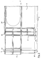
- FIG. 7 shows, in a representation comparable to FIG. 5, two rotary stacking containers 1 according to the prior art, the illustration being partly carried out as a section.
- FIG. 7 shows the left-hand end region of two stacked stack containers 1 arranged one above the other during their superimposition in the longitudinal direction of their longitudinal side walls 3.
- the figure 7 illustrates that in the containers 1 according to the prior art in a first staggered placement of the upper container 1 on the lower container 1 only a limited displacement of the upper container 1 relative to the lower container 1 is possible, however, that a displacement of upper container 1 is not possible in the stacking position. This is due to the fact that, when the upper container 1 according to FIG. 7 is moved from right to left, its lower centering elements 8 start against the upper centering elements 7 of the lower container 1, which makes further shifting impossible.
- the stacking position can only be prepared here by the upper container 1 is placed either immediately from above vertically fitting on the lower container 1 or that the upper container 1 is raised again just before the end of the displacement movement so far that the lower centering 8th of the upper container 1 can pass over the upper centering elements 7 of the lower container 1, which means a difficult handling and an increased effort for the operating personnel.
Landscapes
- Engineering & Computer Science (AREA)
- Mechanical Engineering (AREA)
- Stackable Containers (AREA)
Abstract
Description
Die vorliegende Erfindung betrifft einen Drehstapelbehälter mit einem im wesentlichen rechteckigen Boden und mit je zwei vom Boden aufragenden Längsseitenwänden und Stirnseitenwänden, wobei an wenigstens zwei einander gegenüberliegenden Seitenwänden außenseitig nach außen vorspringende, über einen unteren Teil der Seitenwandhöhe verlaufende Stapelblöcke und innenseitig dazu passende Stapelblocktaschen asymmetrisch so angeordnet sind, daß ein oberer Drehstapelbehälter in einer Stapelstellung auf einen unteren Drehstapelbehälter aufsetzbar und in einer dazu um eine vertikale Achse um 180° verdrehten Neststellung in den unteren Drehstapelbehälter einsetzbar ist, wobei in der Stapelstellung der obere Drehstapelbehälter mit der Unterseite seiner Stapelblöcke auf der Oberseite der Seitenwände des unteren Drehstapelbehälters aufsteht, wobei in der Neststellung der obere Drehstapelbehälter mit seinen Stapelblöcken in den Stapelblocktaschen des unteren Drehstapelbehälters liegt und wobei an der Behälteroberseite und an der Behälterunterseite jeweils Zentrierelemente vorgesehen sind, die in der Stapelstellung in Eingriff miteinander stehen und den oberen Drehstapelbehälter relativ zum unteren Drehstapelbehälter zentrieren und die Drehstapelbehälter gegen ein Verrutschen relativ zueinander in Richtung der Bodenebene sichern.The present invention relates to a rotary stacking container having a substantially rectangular bottom and each with two upstanding from the bottom longitudinal side walls and end walls, wherein on at least two opposing side walls outside outwardly projecting, extending over a lower part of the side wall height stacking blocks and inside matching stacking block pockets asymmetrically so are arranged that an upper stacking stack container can be placed in a stacking position on a lower stacking container and rotated in a rotated about a vertical axis by 180 ° nest position in the lower stacking container, wherein in the stacking position of the upper stacking stack container with the bottom of its stacking blocks on the top the side walls of the lower rotary stacking container stands up, wherein in the nest position of the upper stacking stack container with its stacking blocks in the stacking block pockets of the lower rotating stacker and wherein on the container top and on the container bottom each centering elements are provided which are in the stacking position in engagement with each other and center the upper stacking stack container relative to the lower stacking container and secure the stacking containers against slipping relative to each other in the direction of the ground plane.
Drehstapelbehälter der vorstehend angegebenen Art sind aufgrund ihrer weiten Verbreitung im Bereich der Lagerung und des Transports von Gütern, beispielsweise Lebensmitteln, allgemein bekannt. Die Drehstapelbehälter sind wahlweise übereinander stapelbar oder in ineinander nestbar, wodurch ein Transport von leeren, genesteten Behältern wenig Transportraum beansprucht. Die Drehstapelbehälter haben sich deshalb als Mehrwegbehälter für viele Verwendungszwecke inzwischen bewährt.Rotary stacking containers of the type mentioned above are generally known due to their wide use in the field of storage and transport of goods, such as food. The rotating stack containers are optionally stackable or nested in one another, whereby a transport of empty, nested containers requires little transport space. The stacking containers have therefore proven to be reusable containers for many uses now.
Als nachteilig wird bei den bekannten Drehstapelbehältern angesehen, daß eine Stapelung nur dann möglich ist, wenn der obere Behälter genau von oben her auf den unteren Behälter exakt aufgesetzt wird. Insbesondere bei schweren, gefüllten Behältern ist diese Handhabung für das Bedienungspersonal ungünstig, weil ein hoher Kraftaufwand und ein sehr genaues Positionieren erforderlich sind.A disadvantage is considered in the known rotary stacking containers, that a stacking is only possible if the upper container is placed exactly from above to the lower container exactly. Especially with heavy, filled containers this handling is unfavorable for the operator, because a high force and a very accurate positioning are required.
Für die vorliegende Erfindung stellt sich deshalb die Aufgabe, den bekannten Drehstapelbehälter dahingehend zu verbessern, daß das Stapeln von Behältern übereinander für das Bedienungspersonal vereinfacht wird.For the present invention, therefore, the task is to improve the known stacked rotary container in that the stacking of containers one above the other is simplified for the operator.
Die Lösung dieser Aufgabe gelingt erfindungsgemäß mit einem Drehstapelbehälter der eingangs genannten Art, der dadurch gekennzeichnet ist, daß auf der Oberseite mindestens zweier einander gegenüberliegender Seitenwände jeweils wenigstens eine in Längsrichtung der Seitenwand verlaufende, erhabene Gleitrippe einer solchen Höhe angeordnet ist, daß auf den Gleitrippen ein oberer Drehstapelbehälter relativ zu einem unteren Drehstapelbehälter in Längsrichtung der Gleitrippen aus einer relativ zum unteren Drehstapelbehälter in Längsrichtung der Gleitrippen versetzten Aufsetzstellung gleitend in die Stapelstellung verschiebbar ist.The solution of this object is achieved according to the invention with a rotary stacking container of the type mentioned, which is characterized in that on the upper side of at least two opposing side walls each having at least one extending in the longitudinal direction of the side wall, raised sliding rib of such a height is arranged that on the sliding ribs upper rotary stacking container relative to a lower rotating stack container in the longitudinal direction of the sliding ribs from a relative to the lower rotating stack container in the longitudinal direction of the sliding ribs offset Aufsetzstellung slidably into the stacking position is displaceable.
Mit der Erfindung wird vorteilhaft erreicht, daß ein oberer Drehstapelbehälter zunächst unter nur teilweiser Überdeckung mit einem unteren Drehstapelbehälter auf diesen aufgesetzt werden kann und daß dann durch einfaches Verschieben des oberen Drehstapelbehälters in Längsrichtung der Gleitrippen der obere Drehstapelbehälter in die gewünschte Stapelstellung relativ zum unteren Drehstapelbehälter gebracht werden kann, ohne daß das Verschieben des oberen Drehstapelbehälters relativ zum unteren Drehstapelbehälter durch die Zentrierelemente oder andere Teile der Drehstapelbehälter behindert wird. Hierdurch wird die Handhabung der Drehstapelbehälter insbesondere im schweren, beladenen Zustand für das Bedienungspersonal wesentlich vereinfacht und die Stapelung von Behältern geht leichter und schneller vonstatten. Hierdurch wird das Bedienungspersonal körperlich entlastet und zugleich ein rationelleres Arbeiten erreicht.With the invention is advantageously achieved that an upper stacking stack container initially under only partial overlap with a lower stacking container can be placed on this and that then brought by simply moving the upper stacking container in the longitudinal direction of the sliding ribs of the upper stacking stack container in the desired stacking position relative to the lower stacking container can be, without the displacement of the upper rotating stack container is hindered relative to the lower stacking stack container by the centering or other parts of the rotary stacking container. As a result, the handling of the rotating stack container, especially in the heavy, loaded condition for the operator is much easier and the stacking of containers is easier and faster vonstatten. As a result, the operator is physically relieved and at the same time achieves a more rational work.
Weiterhin ist erfindungsgemäß bevorzugt vorgesehen, daß die Gleitrippen nur auf den Längsseitenwänden oder nur auf den Stirnseitenwänden vorgesehen sind. So ausgeführte Drehstapelbehälter lassen sich dann zwar nur in Richtung ihrer Längsachse oder in Richtung ihrer Querachse beim Herstellen von Behälterstapeln verschieben, was aber in der Regel nicht zu Problemen führt, weil sich Bedienungspersonen, die die Stapel herstellen, sehr schnell an die passende Art und Weise der Herstellung des Behälterstapels gewöhnen werden.Furthermore, it is preferably provided according to the invention that the sliding ribs are provided only on the longitudinal side walls or only on the end side walls. Although rotating stacking containers designed in this way can then only be displaced in the direction of their longitudinal axis or in the direction of their transverse axis during the production of container stacks, this does not generally lead to problems because operators who produce the stacks move very quickly to the appropriate manner get used to the production of the container stack.
Um beim Stapeln von Behältern ein gleitendes Anheben des jeweils obersten Behälters zu ermöglichen, ist weiter vorgesehen, daß die Gleitrippen an ihren Enden jeweils abgerundet oder abgeschrägt geformt sind. Außerdem werden durch diese Form der Gleitrippenenden an der Oberseite der Seitenwände Verletzungsgefahren für das Bedienungspersonal oder Beschädigungsgefahren für transportierte Güter vermieden.In order to enable a sliding lifting of the respective uppermost container when stacking containers, it is further provided that the sliding ribs are respectively rounded or bevelled at their ends. In addition, this shape of the Gleitrippenenden at the top the sidewalls avoided injury to the operator or damage to transported goods.
Eine weitere vorteilhafte Ausgestaltung des erfindungsgemäßen Drehstapelbehälters sieht vor, daß an der Unterseite der an den mit den Gleitrippen ausgestatteten Seitenwänden liegenden Stapelblöcke jeweils wenigstens eine mit der zugehörigen Gleitrippe eines unteren Drehstapelbehälters zusammenwirkende, nach unten vorstehende Gleitkufe vorgesehen ist. Mittels der Gleitkufen wird zum einen eine sichere Führung des oberen Drehstapelbehälters auf den darunter angeordneten Drehstapelbehälter beim Verschieben erreicht. Außerdem wird so für eine niedrige Reibung und einen vorteilhaft geringen Kraftaufwand für das Verschieben des oberen Drehstapelbehälters relativ zum unteren Drehstapelbehälter gesorgt. Außerdem können die Gleitkufen mit dazu genutzt werden, die gewünschte Anhebung des oberen Drehstapelbehälters relativ zum unteren Drehstapelbehälter während des Verschiebens zu bewirken, solange die Gleitkufen auf den Gleitrippen aufliegen. Auf diese Weise wird insbesondere ermöglicht, die Gleitrippen relativ niedrig auszubilden, sodaß sie an der Oberseite des Drehstapelbehälters nicht störend in Erscheinung treten.A further advantageous embodiment of the rotary stacking container according to the invention provides that at least one of the underside of the arranged with the sliding ribs side walls stack blocks at least one cooperating with the associated sliding rib of a lower rotating stack container, downwardly projecting skid is provided. By means of the skids on the one hand, a secure guidance of the upper rotating stack container is achieved on the arranged underneath the stacking container when moving. In addition, it is provided for a low friction and an advantageous low effort for moving the upper stacking container relative to the lower stacking container. In addition, the skids may be used to cause the desired elevation of the upper rotating stacking container relative to the lower rotating stacking container during shifting as long as the skids rest on the sliding ribs. In this way, in particular makes it possible to form the sliding ribs relatively low, so that they do not interfere with the top of the rotary stacking container in appearance.
Um den Herstellungsaufwand für den erfindungsgemäßen Drehstapelbehälter niedrig zu halten und um sowohl für die Gleitrippen als auch für die Gleitkufen eine hohe Stabilität und Dauerhaltbarkeit zu gewährleisten, sind bevorzugt die Gleitrippen und die Gleitkufen jeweils einstückig an die zugehörige Seitenwand angeformt.In order to keep the production costs for the rotating stack container according to the invention low and to ensure a high stability and durability for both the sliding ribs and for the skids, the sliding ribs and the skids are preferably integrally formed respectively on the associated side wall.
In einer bevorzugten Ausführung des Drehstapelbehälters sind an jeder Längsseitenwand in deren Längsrichtung voneinander beabstandet zwei Stapelblöcke vorgesehen und es entspricht jeweils die Länge der Gleitrippe dem lichten Abstand zwischen den beiden Gleitkufen der beiden Stapelblöcke der Längsseitenwand abzüglich eines Bewegungsspielmaßes, wobei in der Stapelstellung jede Gleitrippe zwischen je zwei Gleitkufen liegt. In dieser Ausgestaltung hat die Gleitrippe einen durchgehenden, unterbrechungsfreien Verlauf, wodurch ein großer Verschiebungsweg für den oberen Drehstapelbehälter relativ zum unteren Drehstapelbehälter ermöglicht wird. In der Stapelstellung der übereinander angeordneten Drehstapelbehälter liegen jeweils die beiden Gleitkufen auf jeder Längsseite des oberen Behälters beiderseits der Gleitrippe des unteren Behälters, ohne Kontakt zur Gleitrippe zu haben, wodurch nun die Gleitrippen und -kufen außer Funktion sind. In dieser Stapelstellung steht der obere Drehstapelbehälter mit der Unterseite seiner Stapelblöcke auf der Oberseite des unteren Drehstapelbehälters auf. Die nun in Eingriff stehenden Zentrierelemente sichern die gestapelten Drehstapelbehälter gegen eine unerwünschte Verschiebung relativ zueinander parallel zur Bodenebene, in der Praxis also üblicherweise in Horizontalrichtung.In a preferred embodiment of the rotary stacking container, two stacking blocks are provided at each longitudinal side wall in the longitudinal direction of each other spaced apart and it each corresponds to the length of the sliding rib the clearance between the two skids of the two stacking blocks of the longitudinal side wall minus a Bewegungsspielmaßes, wherein in the stacking position each sliding rib between two skids. In this embodiment, the sliding rib has a continuous, uninterrupted course, whereby a large displacement path for the upper rotating stack container is made possible relative to the lower rotating stack container. In the stacking position of the stacked stacking containers are each the two skids on each longitudinal side of the upper container on both sides of the sliding rib of the lower container to have no contact with the sliding rib, which now the sliding ribs and skids are inoperative. In this stacking position, the upper rotary stacking container stands with the underside of its stacking blocks on top of the lower rotary stacking container. The centering elements which are now in engagement secure the stacked stacking containers against an undesired displacement relative to one another parallel to the ground plane, ie in practice usually in the horizontal direction.
Weiter ist bevorzugt vorgesehen, daß jede Gleitrippe sich nur über den Bereich der Oberseite der Längsseitenwand zwischen zwei Stapelblocktaschen erstreckt. Hiermit wird für einen unterbrechungsfreien Verlauf der Gleitrippe über eine möglichst große Länge gesorgt, wobei zweckmäßig und vorteilhaft die Stapelblocktaschen der Längsseitenwände so nah wie möglich zu den Stirnseitenwänden des Drehstapelbehälters liegen.Further, it is preferably provided that each sliding rib extends only over the region of the upper side of the longitudinal side wall between two stacking block pockets. This is taken care of for an interruption-free course of the sliding rib over the largest possible length, and expediently and advantageously the stacking block pockets of the longitudinal side walls are as close as possible to the end walls of the rotary stacking container.
Um mit einer möglichst geringen Höhe der Gleitrippen und der Gleitkufen auskommen zu können, schlägt eine weitere Ausgestaltung des Drehstapelbehälters gemäß Erfindung vor, daß die Zentrierelemente an der Oberseite des Drehstapelbehälters jeweils eine zum Inneren des Drehstapelbehälters abfallende Schräge oder Abrundung und/oder die Zentrierelemente an der Unterseite des Drehstapelbehälters jeweils eine zum Äußeren des Drehstapelbehälters ansteigende Schräge oder Abrundung aufweisen. In dieser Ausführung können die zusammenwirkenden Zentrierelemente beim Verschieben des oberen Behälters übereinander hinweggleiten, ohne daß es zu einer Behinderung der Verschiebungsbewegung kommt. Der obere Drehstapelbehälter wird lediglich beim Auflaufen seiner unterseitigen Zentrierelemente auf die oberseitigen Zentrierelemente des unteren Drehstapelbehälters leicht angehoben, um danach in seine Stapelstellung zu fallen. Das Bedienungspersonal erhält hierdurch zudem ein deutliches Signal für das Erreichen der korrekten Stapelstellung des jeweils neu aufgesetzten Drehstapelbehälters.In order to be able to manage with the lowest possible height of the sliding ribs and the skids, proposes a further embodiment of the rotary stacking container according to the invention that the centering on the top of the rotary stacking container each have a sloping to the interior of the rotating stack container slope or rounding and / or the centering on the underside of the rotary stacking container each having a rising to the outside of the rotary stacking container slope or rounding. In this embodiment, the cooperating centering elements when sliding the upper container slide over each other, without causing a hindrance to the displacement movement. The upper rotating stack container is slightly lifted only when running its lower-side centering on the upper-side centering of the lower rotating stack container, to then fall into its stacking position. In addition, the operator receives a clear signal for the achievement of the correct stacking position of the newly placed rotary stacking container.
Um die Zentrierelemente in ihrer Form einfach zu halten und gleichzeitig stabil zu machen, haben die Zentrierelemente bevorzugt die Form von Nocken oder Rippen.In order to keep the centering elements simple in their shape and at the same time to make them stable, the centering elements preferably have the form of cams or ribs.
Damit der Drehstapelbehälter kostengünstig als Massenprodukt hergestellt werden kann, ist er vorzugsweise ein einstückiges Spritzgußteil aus Kunststoff.In order that the rotary stacking container can be inexpensively mass-produced, it is preferably a one-piece plastic injection-molded part.
Ein Ausführungsbeispiel des erfindungsgemäßen Drehstapelbehälters sowie ein Beispiel für einen aus dem Stand der Technik bekannten Drehstapelbehälter werden im folgenden anhand einer Zeichnung erläutert. Die Figuren der Zeichnung zeigen:
Figur 1- einen Drehstapelbehälter gemäß Erfindung in einer perspektivischen Gesamtansicht,
Figur 2- den Drehstapelbehälter aus
Figur 1 in Ansicht auf den linken Endbereich einer seiner Längsseitenwände, Figur 3- den Drehstapelbehälter aus
Figur 1 in Seitenansicht auf den rechten Endbereich seiner Längsseitenwand, Figur 4- zwei Drehstapelbehälter während ihres Stapelns übereinander in Ansicht auf je eine der Längsseitenwände der beiden Behälter,
Figur 5- den linken Endbereich der Längsseitenwände der gestapelten Behälter aus
Figur 4, Figur 6- den rechten Endbereich der Längsseitenwände der gestapelten Behälter aus
Figur 4 und Figur 7- einen Ausschnitt aus dem linken Endbereich von zwei übereinander angeordneten Drehstapelbehältern gemäß dem Stand der Technik in Seitenansicht während eines Verschiebens relativ zueinander.
- FIG. 1
- a rotary stacking container according to the invention in a perspective overall view,
- FIG. 2
- 1 in view of the left end region of one of its longitudinal side walls,
- FIG. 3
- 1 in side view on the right end region of its longitudinal side wall,
- FIG. 4
- two stacked stack containers during stacking on top of each other in view of one of the longitudinal side walls of the two containers,
- FIG. 5
- the left end region of the longitudinal side walls of the stacked containers of Figure 4,
- FIG. 6
- the right end portion of the longitudinal side walls of the stacked container of Figure 4 and
- FIG. 7
- a detail of the left end of two stacked stacked containers according to the prior art in side view during a displacement relative to each other.
Figur 1 zeigt einen Drehstapelbehälter 1 gemäß Erfindung in einer perspektivischen Gesamtansicht schräg von oben. Den unteren Teil des Behälters 1 bildet ein hier nicht sichtbarer, in Draufsicht rechteckiger Boden 2. Von den vier Seiten des Bodens 2 erstrecken sich einstückig mit diesem zwei längere Längsseitenwände 3 und zwei kürzere Stirnseitenwände 4 nach oben. Im gezeigten Beispiel ist der Drehstapelbehälter 1 ein einstückiges Spritzgußteil aus Kunststoff. Auf der Außenseite aller Seitenwände 3 und 4 sind je zwei nach außen vorspringende Stapelblöcke 5 angeformt, die sich hier über etwa die untere Hälfte der Höhe des Behälters 1 erstrecken.Figure 1 shows a
An den Innenseiten aller vier Seitenwände 3, 4 sind in deren oberer Hälfte entsprechend den Abmessungen der Stapelblöcke 5 bemaßte Stapelblocktaschen 6 eingeformt.On the insides of all four
Die Stapelblöcke 5 und die Stapelblocktaschen 6 sind dabei an den Wänden 3 und 4 des Drehstapelbehälters 1 in einer asymmetrischen Lage so angeordnet, daß in einer ersten Stellung eines oberen Drehstapelbehälter 1 dieser auf einen unteren Behälter 1 stapelbar ist und in einer dazu um eine senkrecht zur Bodenebene 2 verlaufenden Achse um 180° verdrehten Stellung des oberen Behälters 1 dieser in den unteren Behälter 1 einsetzbar, also nestbar, ist. In der Stapelstellung steht ein oberer Behälter 1 mit der Unterseite seiner Stapelblöcke 5 auf dem oberen Rand der vier Seitenwände 3, 4 des unteren Behälters 1 auf. In dieser Lage werden die übereinander gestapelten Behälter 1 relativ zueinander durch Zentrierelemente 7 an der Oberseite der Seitenwände 3, 4 und weitere Zentrierelemente 8 (vergleiche Figur 2 und 3) an der Unterseite des Behälters 1 relativ zueinander zentriert und gegen eine Verschiebung relativ zueinander in einer Richtung parallel zur Ebene des Bodens 2 gesichert.The stacking
Soweit wie bisher beschrieben entspricht der dargestellte Drehstapelbehälter 1 herkömmlichen, bekannten Drehstapelbehältern. Neu und wesentlich bei dem in Figur 1 dargestellten Drehstapelbehälter 1 sind zwei Gleitrippen 31, die auf der Oberseite der Längsseitenwände 3 angeformt sind. Die Gleitrippen 31 ragen über die Oberseite der Längsseitenwände 3 nach oben hin vor und bilden eine von jeweils einer ersten Stapelblocktasche 6 zu einer zweiten Stapelblocktasche 6 der jeweiligen Längsseitenwand 3 durchgehende, unterbrechungsfreie Gleitbahn für einen aufzustapelnden weiteren Drehstapelbehälter 1.As far as described so far corresponds to the illustrated
Die Gleitbahnen 31 bieten die Möglichkeit, einen aufzustapelnden weiteren Drehstapelbehälter 1 zunächst mit einem Versatz parallel zu den Längsseitenwänden 3 auf den unteren Drehstapelbehälter aufzusetzen und dann in seine Stapelstellung einfach entlang der Gleitrippen 31 zu verschieben. Am Ende der Verschiebungsbewegung fällt dann der obere Drehstapelbehälter 1 in seine Stapelstellung auf den unteren Drehstapelbehälter 1, wobei dann die erwähnten Zentrierelemente 7, 8 in Eingriff miteinander gelangen. Die Verschiebungsbewegung wird aufgrund der erhabenen Gleitrippen 31 dabei durch die Zentrierelemente 7, 8 vorteilhaft nicht behindert. Dies erleichtert das Herstellen von Stapeln aus den Drehstapelbehältern 1 für das Bedienungspersonal wesentlich. Zusätzlich oder alternativ zum Beispiel in Figur 1 können entsprechende Gleitrippen auf der Oberseite der Stirnseitenwände 4 vorgesehen sein.The
Figur 2 zeigt in vergrößerter Darstellung den linken Endbereich der in Figur 1 dem Betrachter zugewandten Längsseitenwand 3 in Seitenansicht. Unten in Figur 2 liegt der Boden 2 des Drehstapelbehälters 1; links in Figur 2 liegt eine der beiden Stirnseitenwände 4. Mit Abstand von der linken Stirnseitenwand 4 nach rechts versetzt liegt in der unteren Hälfte der Längsseitenwand 3 der eine der beiden Stapelblöcke 5 dieser Längsseitenwand 3. Der Stapelblock 5 ist hier aus einer Anordnung von drei in Vertikalrichtung verlaufenden parallelen Rippen gebildet, die durch mehrere Querrippen miteinander verbunden sind. Am linken Ende der Unterseite des Stapelblocks 5 ist eine Gleitkufe 51 angeformt, die beim Aufsetzen eines Drehstapelbehälters 1 auf einen unteren Drehstapelbehälter 1 auf der zugehörigen Gleitrippe 31 des unteren Drehstapelbehälters 1 aufsetzt. Beim Verschieben des oberen Drehstapelbehälters 1 relativ zum unteren Drehstapelbehälter 1 gleitet der obere Drehstapelbehälter 1 mit einem Paar seinen Gleitkufen 51, die an allen vier Stapelblöcken 5 der beiden Längsseitenwände 3 vorgesehen sind, auf den Gleitrippen 31 des unteren Behälters 1.Figure 2 shows an enlarged view of the left end portion of the viewer in Fig. 1 facing
Links oben in Figur 2 ist eines der Zentrierelemente 7 an der Oberseite des Behälters 1 erkennbar. Dieses Zentrierelement 7 besitzt eine in Richtung zum Inneren des Behälters 1 hin abfallende Schräge oder Abrundung 71.On the top left in FIG. 2, one of the centering
Links unten in Figur 2 ist eines der Zentrierelemente 8 an der Unterseite des Drehstapelbehälters 1 sichtbar. Diese Zentrierelemente 8 besitzen jeweils eine zum äußeren des Behälters 1 hin ansteigende Schräge oder Abrundung 81. Sowohl die Zentrierelemente 7 als auch die Zentrierelemente 8 sind hier in Form von erhabenen Rippen ausgeführt.2, one of the centering
Auf der Oberseite der Längsseitenwand 3 ist ein Abschnitt der Gleitrippe 31 sichtbar, deren Ende 32 abgerundet ausgeführt ist. In dem Bereich links von dem abgerundeten Ende 32 der Gleitrippe 31 liegt zum Inneren des Behälters 1 eine hier von außen nicht sichtbare Stapelblocktasche.On the upper side of the
Figur 3 zeigt in gleiche Darstellungsweise wie die Figur 2 den rechten Endbereich der Längsseitenwand 3. Auch hier liegt unten der Boden 2 des Drehstapelbehälters 1, von dem aus die Längsseitenwand 3 sich nach oben erstreckt. Ganz rechts in Figur 3 liegt die in Figur 1 rechte Stirnseitenwand 4 des Behälters 1. Unten rechts liegt auf der Längsseitenwand 3 der rechte der beiden Stapelblöcke 5 dieser Längsseitenwand 3. Bei diesem Stapelblock 5 ist eine Gleitkufe 51 am rechten Ende der Unterseite angeformt.Figure 3 shows in the same representation as the figure 2 the right end of the
Rechts oben in Figur 3 ist eines der Zentrierelemente 7 an der Oberseite des Behälters 1 sichtbar; rechts unten in Figur 3 sieht man eines der Zentrierelemente 8 an der Unterseite des Drehstapelbehälters 1. Das oben liegende Zentrierelement 7 hat hier ebenfalls eine zum Inneren des Behälters 1 hin abfallende Schräge oder Abrundung 71. Entsprechend ist auch das untere Zentrierelement 8 mit einer zum Behälteräußeren hin ansteigenden Schräge oder Rundung 81 ausgebildet. Oberhalb des unteren Zentrierelements 8 ist in Figur 3 noch der vordere Stapelblock 5 der Stirnseitenwand 4 sichtbar.At the top right in FIG. 3, one of the centering
Figur 4 zeigt zwei übereinander angeordnete Drehstapelbehälter 1 während eines Stapelvorganges kurz vor Erreichen der Stapelstellung des oberen Drehstapelbehälters 1.FIG. 4 shows two stacking
Zur Herstellung eines Behälterstapels aus mehreren Drehstapelbehältern 1 wird hier ein oberer Behälter 1 zunächst mit einem Versatz in Richtung der Längsseitenwände 3, hier gemäß Figur 4 von rechts her, auf den darunter angeordneten Drehstapelbehälter 1 aufgesetzt. Anschließend wird der obere Behälter 1 gemäß Figur 4 von rechts nach links in Richtung der Längsseitenwände 3 relativ zum unteren Drehstapelbehälter 1 verschoben. In seinem in Figur 4 linken Bereich gleitet dabei der obere Drehstapelbehälter 1 mit seinen dort vorgesehenen zwei Gleitkufen 51 über die Gleitrippen 31 an der Oberseite des unteren Drehstapelbehälters 1.For producing a container stack from a plurality of
In seinem rechten Teil gleitet dabei gleichzeitig der obere Drehstapelbehälter 1 mit der glatten Unterseite seines Bodens 2 über die rechte Stirnseitenwand 4 des unteren Behälters 1.At the same time, in its right part, the upper
Der Zustand der beiden Drehstapelbehälter 1 aus Figur 4 ist in Figur 5 anhand eines Ausschnitts aus dem linken Endbereich der beiden Behälter 1 vergrößert dargestellt. Hier wird besonders deutlich erkennbar, daß der obere Behälter 1 mit seinen Gleitkufen 51 an der dem Betrachter zugewandten Längsseitenwand 3 und gleichzeitig an der dem Betrachter abgewandten, gegenüberliegenden zweiten Längsseitenwand 3 auf den oberseitigen Gleitrippen 31 des unteren Behälters 1 gleitet.The state of the two stacked
Links an den Stirnseitenwänden 4 der beiden Behälter 1 sind deren obere Zentrierelemente 7 und untere Zentrierelemente 8 sichtbar. Das obere Zentrierelement 7 des unteren Behälters 1 und das untere Zentrierelement 8 des oberen Behälters 1 stehen dabei kurz vor ihrem Eingriff miteinander. Der Zentriereingriff der Zentrierelemente 7 und 8 wird durch weiteres Verschieben des oberen Behälters 1 gemäß dem daran eingezeichneten Pfeil bewirkt. Der obere Behälter 1 gleitet dabei durch Auflaufen seines unteren Zentrierelements 8 auf das obere Zentrierelement 7 des unteren Behälters 1 weiter nach links. Nachdem das untere Zentrierelement 8 des oberen Behälters 1 sich über das obere Zentrierelement 7 des unteren Behälters 1 hinwegbewegt hat, fällt der obere Behälter 1 um einen geringen Weg, in der Praxis wenige Millimeter, nach unten und gelangt so in seine zentrierte und gesicherte Stapelstellung. Dabei gelangen gleichzeitig die Gleitkufen 51 über das linke Ende 32 der Gleitrippen 31 hinweg, so daß dann die Gleitkufen 51 nicht mehr in Anlage an den Gleitrippen 31 stehen.Left on the
Die Figur 6 zeigt ebenfalls in vergrößerter Ausschnitts-Seitenansicht den rechten Endbereich der beiden Drehstapelbehälter 1 aus Figur 4. Hier wird deutlich sichtbar, daß der obere Behälter 1 mit der glatten Unterseite seines Bodens 2 über die Oberseite der rechten Stirnseitenwand 4, genauer über die Oberseite der oberen Zentrierelemente 7 auf der Oberseite der rechten Stirnseitenwand 4, des unteren Behälters 1 gleitet. Sobald durch weiteres Verschieben des oberen Behälters 1 nach links der Boden 2 sich über die oberen Zentrierelemente 7 des unteren Behälters 1 hinweg bewegt hat, fällt auch der rechte Bereich des Behälters 1 soweit nach unten, bis die Unterseite der hier angeordneten Stapelblöcke 5 des oberen Behälters 1 auf der Oberseite der Längsseitenwand 3 des unteren Behälters 1 aufsetzen. Diese Stapelstellung wird dann durch die Zentrierelemente 7 und 8 gesichert.The figure 6 also shows in an enlarged side view of the right-hand end portion of the two stacking
Figur 7 zeigt in einer mit der Figur 5 vergleichbaren Darstellung zwei Drehstapelbehälter 1 nach dem Stand der Technik, wobei die Darstellung teils als Schnitt ausgeführt ist. Die Figur 7 zeigt dabei den linken Endbereich zweier übereinander angeordneter Drehstapelbehälter 1 während ihres Übereinanderschiebens in Längsrichtung ihrer Längsseitenwände 3.FIG. 7 shows, in a representation comparable to FIG. 5, two
Die Figur 7 verdeutlicht, daß bei den Behältern 1 nach dem Stand der Technik bei einem zunächst versetzten Aufsetzen des oberen Behälters 1 auf den unteren Behälter 1 nur ein begrenztes Verschieben des oberen Behälters 1 relativ zum unteren Behälter 1 möglich ist, daß jedoch ein Verschieben des oberen Behälters 1 bis in die Stapelstellung nicht möglich ist. Dies beruht darauf, daß bei einem Verschieben des oberen Behälters 1 gemäß Figur 7 von rechts nach links dessen untere Zentrierelemente 8 gegen die oberen Zentrierelemente 7 des unteren Behälters 1 anlaufen, wodurch ein weiteres Verschieben unmöglich wird. Die Stapelstellung kann hier nur dadurch hergestellt werden, daß der obere Behälter 1 entweder sofort von oben her vertikal passend auf den unteren Behälter 1 aufgesetzt wird oder daß der obere Behälter 1 kurz vor Ende der Verschiebungsbewegung noch einmal soweit angehoben wird, daß die unteren Zentrierelemente 8 des oberen Behälters 1 über die oberen Zentrierelemente 7 des unteren Behälters 1 gelangen können, was eine erschwerte Handhabung und einen erhöhten Kraftaufwand für das Bedienungspersonal bedeutet.The figure 7 illustrates that in the
Claims (10)
dadurch gekennzeichnet,
daß auf der Oberseite mindestens zweier einander gegenüberliegender Seitenwände (3, 4) jeweils wenigstens eine in Längsrichtung der Seitenwand (3, 4) verlaufende, erhabene Gleitrippe (31) einer solchen Höhe angeordnet ist, daß auf den Gleitrippen (31) ein oberer Drehstapelbehälter (1) relativ zu einem unteren Drehstapelbehälter (1) in Längsrichtung der Gleitrippen (31) aus einer relativ zum unteren Drehstapelbehälter (1) in Längsrichtung der Gleitrippen (31) versetzten Aufsetzstellung gleitend in die Stapelstellung verschiebbar ist.Rotary stacking container (1) having a substantially rectangular bottom (2) and each with two longitudinal side walls (3) and front side walls (4) projecting from the bottom (2), wherein on at least two opposite side walls (3, 4) projecting outwards on the outside, Stacking blocks (5) extending over a lower part of the side wall height and stacking block pockets (6) matching inside are arranged asymmetrically so that an upper stacked rotary container (1) can be placed in a stacking position on a lower stacked rotary container (1) and in a vertical axis about it in the stacking position, the upper rotating stack container (1) with the bottom of its stacking blocks (5) on the top of the side walls (3, 4) of the lower rotating stacker container (1) stands up in which, in the nest position, the upper rotating stack container 1 with its stacking blocks (5) in the stacking block pockets (FIG. 6) of the lower rotary stacking container (1) and wherein on the container top and on the container bottom each centering elements (7, 8) are provided which are in the stacking position in engagement with each other and the upper stacking rotary container (1) relative to the lower stacking rotary container (1) Center and the stacking container (1) against ensure slippage relative to one another in the direction of the ground plane,
characterized,
in that on the upper side of at least two mutually opposite side walls (3, 4) there is arranged at least one raised sliding rib (31) of such height extending in the longitudinal direction of the side wall (3, 4) that an upper rotating stacking container (31) is mounted on the sliding ribs (31). 1) relative to a lower stacking rotary container (1) in the longitudinal direction of the sliding ribs (31) from a relative to the lower stacking container (1) in the longitudinal direction of the sliding ribs (31) staggered Aufsetzstellung slidably into the stacking position.
Applications Claiming Priority (1)
| Application Number | Priority Date | Filing Date | Title |
|---|---|---|---|
| DE200420014340 DE202004014340U1 (en) | 2004-09-13 | 2004-09-13 | Stack nest containers |
Publications (1)
| Publication Number | Publication Date |
|---|---|
| EP1634815A1 true EP1634815A1 (en) | 2006-03-15 |
Family
ID=35355896
Family Applications (1)
| Application Number | Title | Priority Date | Filing Date |
|---|---|---|---|
| EP05016366A Withdrawn EP1634815A1 (en) | 2004-09-13 | 2005-07-28 | Nestable and stackable container |
Country Status (2)
| Country | Link |
|---|---|
| EP (1) | EP1634815A1 (en) |
| DE (1) | DE202004014340U1 (en) |
Cited By (4)
| Publication number | Priority date | Publication date | Assignee | Title |
|---|---|---|---|---|
| EP1911682A1 (en) * | 2006-10-10 | 2008-04-16 | Rehrig Pacific Company | Stackable and nestable tray |
| JP2013018523A (en) * | 2011-07-12 | 2013-01-31 | Sanko Co Ltd | Container |
| US20140274235A1 (en) * | 2013-03-15 | 2014-09-18 | Agco Corporation | Grain Bin Constructed of Plastic Panels |
| JP2017039500A (en) * | 2015-08-17 | 2017-02-23 | 三甲株式会社 | container |
Families Citing this family (1)
| Publication number | Priority date | Publication date | Assignee | Title |
|---|---|---|---|---|
| DE202011051215U1 (en) * | 2011-09-06 | 2012-09-10 | Hermesmeyer & Greweling Gmbh & Co.Kg | Standard container in the manner of a box-shaped rotating stacker |
Citations (2)
| Publication number | Priority date | Publication date | Assignee | Title |
|---|---|---|---|---|
| US3934724A (en) * | 1974-01-17 | 1976-01-27 | Phillips Petroleum Company | Nest and stack container |
| US20030183549A1 (en) * | 2002-03-26 | 2003-10-02 | Donald Verna | Stackable tray having anti-pivot stop and wash apertures |
Family Cites Families (7)
| Publication number | Priority date | Publication date | Assignee | Title |
|---|---|---|---|---|
| DE1825467U (en) * | 1960-11-21 | 1961-01-19 | Bayha & Strackbein G M B H | STACKABLE TRANSPORT BOX. |
| DE8708004U1 (en) * | 1987-06-05 | 1987-08-06 | Fritz Schäfer GmbH, 5908 Neunkirchen | Plastic storage and/or transport containers |
| DE9005131U1 (en) * | 1990-05-07 | 1990-09-06 | Ringoplast GmbH, 4459 Ringe | Plastic device for transporting baked goods |
| DE9320047U1 (en) * | 1993-12-28 | 1995-05-04 | TLT Transport- und Lagertechnik GmbH, 49824 Ringe | Stackable transport box |
| DE29904563U1 (en) * | 1999-03-12 | 1999-06-10 | Ruch Novaplast GmbH + Co. KG., 77704 Oberkirch | Stackable packaging |
| CH694162A5 (en) * | 2000-02-29 | 2004-08-13 | Utz Georg Holding Ag | Foldable Stapelbehaelter. |
| DE10063961A1 (en) * | 2000-08-31 | 2002-03-21 | Linpac Stucki Kunststoffverarb | Crate for bakery industry has horizontal studs along its longer sides, tops of these sides having notches, allowing full crates to be stacked, and angled slots between notches, allowing empty crates to be stacked inside each other |
-
2004
- 2004-09-13 DE DE200420014340 patent/DE202004014340U1/en not_active Expired - Lifetime
-
2005
- 2005-07-28 EP EP05016366A patent/EP1634815A1/en not_active Withdrawn
Patent Citations (2)
| Publication number | Priority date | Publication date | Assignee | Title |
|---|---|---|---|---|
| US3934724A (en) * | 1974-01-17 | 1976-01-27 | Phillips Petroleum Company | Nest and stack container |
| US20030183549A1 (en) * | 2002-03-26 | 2003-10-02 | Donald Verna | Stackable tray having anti-pivot stop and wash apertures |
Cited By (5)
| Publication number | Priority date | Publication date | Assignee | Title |
|---|---|---|---|---|
| EP1911682A1 (en) * | 2006-10-10 | 2008-04-16 | Rehrig Pacific Company | Stackable and nestable tray |
| US7922001B2 (en) | 2006-10-10 | 2011-04-12 | Rehrig Pacific Company | Stackable and nestable tray |
| JP2013018523A (en) * | 2011-07-12 | 2013-01-31 | Sanko Co Ltd | Container |
| US20140274235A1 (en) * | 2013-03-15 | 2014-09-18 | Agco Corporation | Grain Bin Constructed of Plastic Panels |
| JP2017039500A (en) * | 2015-08-17 | 2017-02-23 | 三甲株式会社 | container |
Also Published As
| Publication number | Publication date |
|---|---|
| DE202004014340U1 (en) | 2006-02-02 |
Similar Documents
| Publication | Publication Date | Title |
|---|---|---|
| DE69708116T2 (en) | CONTAINER | |
| DE10026149C2 (en) | Stackable transport container | |
| DE1586559B1 (en) | Stackable and nested containers | |
| EP0332186A2 (en) | Moulded end wall for cores of rolled material | |
| EP3636559B1 (en) | Stackable box | |
| EP3566968A2 (en) | Container system with frame member | |
| DE1286443B (en) | Stackable and nestable container | |
| DE202014101556U1 (en) | Containers for the transport and storage of goods | |
| EP2497727A2 (en) | Tray with folding support | |
| DE2255316C3 (en) | Bottle crate | |
| DE19641270B4 (en) | Device for stacking and transporting molded parts | |
| DE4103479A1 (en) | DEVICE FOR ADJUSTING THE RECORDING VOLUME OF A WORKPIECE CARRIER | |
| EP3992096B1 (en) | Plastic container | |
| EP1634815A1 (en) | Nestable and stackable container | |
| DE1278931B (en) | Stackable and nestable container | |
| DE2350810A1 (en) | DEVICE FOR MANUFACTURING CONTAINERS | |
| EP0698558A2 (en) | Stackable transportcontainer | |
| DE1296081B (en) | Transport box system with boxes of different sizes | |
| EP1747875B1 (en) | Device for piling up of parts made of thermoplastic material | |
| EP1733975A1 (en) | Collapsible Container | |
| EP3305678B1 (en) | Transport and storage device | |
| EP0634334A1 (en) | Storage container with guiding elements | |
| EP3363748B1 (en) | Stackable and nestable container | |
| DE69016044T2 (en) | BOTTLE BOX. | |
| EP3012205B1 (en) | Divisible crate for bottles |
Legal Events
| Date | Code | Title | Description |
|---|---|---|---|
| PUAI | Public reference made under article 153(3) epc to a published international application that has entered the european phase |
Free format text: ORIGINAL CODE: 0009012 |
|
| AK | Designated contracting states |
Kind code of ref document: A1 Designated state(s): AT BE BG CH CY CZ DE DK EE ES FI FR GB GR HU IE IS IT LI LT LU LV MC NL PL PT RO SE SI SK TR |
|
| AX | Request for extension of the european patent |
Extension state: AL BA HR MK YU |
|
| AKX | Designation fees paid | ||
| STAA | Information on the status of an ep patent application or granted ep patent |
Free format text: STATUS: THE APPLICATION IS DEEMED TO BE WITHDRAWN |
|
| 18D | Application deemed to be withdrawn |
Effective date: 20060916 |
|
| REG | Reference to a national code |
Ref country code: DE Ref legal event code: 8566 |