EP1619666B1 - Speech decoder, speech decoding method, program, recording medium - Google Patents
Speech decoder, speech decoding method, program, recording medium Download PDFInfo
- Publication number
- EP1619666B1 EP1619666B1 EP03721013A EP03721013A EP1619666B1 EP 1619666 B1 EP1619666 B1 EP 1619666B1 EP 03721013 A EP03721013 A EP 03721013A EP 03721013 A EP03721013 A EP 03721013A EP 1619666 B1 EP1619666 B1 EP 1619666B1
- Authority
- EP
- European Patent Office
- Prior art keywords
- formant
- vocal tract
- amplification
- tract characteristic
- vocal
- Prior art date
- Legal status (The legal status is an assumption and is not a legal conclusion. Google has not performed a legal analysis and makes no representation as to the accuracy of the status listed.)
- Expired - Lifetime
Links
Images


Classifications
-
- G—PHYSICS
- G10—MUSICAL INSTRUMENTS; ACOUSTICS
- G10L—SPEECH ANALYSIS TECHNIQUES OR SPEECH SYNTHESIS; SPEECH RECOGNITION; SPEECH OR VOICE PROCESSING TECHNIQUES; SPEECH OR AUDIO CODING OR DECODING
- G10L19/00—Speech or audio signals analysis-synthesis techniques for redundancy reduction, e.g. in vocoders; Coding or decoding of speech or audio signals, using source filter models or psychoacoustic analysis
- G10L19/04—Speech or audio signals analysis-synthesis techniques for redundancy reduction, e.g. in vocoders; Coding or decoding of speech or audio signals, using source filter models or psychoacoustic analysis using predictive techniques
- G10L19/26—Pre-filtering or post-filtering
-
- G—PHYSICS
- G10—MUSICAL INSTRUMENTS; ACOUSTICS
- G10L—SPEECH ANALYSIS TECHNIQUES OR SPEECH SYNTHESIS; SPEECH RECOGNITION; SPEECH OR VOICE PROCESSING TECHNIQUES; SPEECH OR AUDIO CODING OR DECODING
- G10L21/00—Speech or voice signal processing techniques to produce another audible or non-audible signal, e.g. visual or tactile, in order to modify its quality or its intelligibility
- G10L21/02—Speech enhancement, e.g. noise reduction or echo cancellation
- G10L21/0316—Speech enhancement, e.g. noise reduction or echo cancellation by changing the amplitude
- G10L21/0364—Speech enhancement, e.g. noise reduction or echo cancellation by changing the amplitude for improving intelligibility
-
- G—PHYSICS
- G10—MUSICAL INSTRUMENTS; ACOUSTICS
- G10L—SPEECH ANALYSIS TECHNIQUES OR SPEECH SYNTHESIS; SPEECH RECOGNITION; SPEECH OR VOICE PROCESSING TECHNIQUES; SPEECH OR AUDIO CODING OR DECODING
- G10L19/00—Speech or audio signals analysis-synthesis techniques for redundancy reduction, e.g. in vocoders; Coding or decoding of speech or audio signals, using source filter models or psychoacoustic analysis
- G10L19/04—Speech or audio signals analysis-synthesis techniques for redundancy reduction, e.g. in vocoders; Coding or decoding of speech or audio signals, using source filter models or psychoacoustic analysis using predictive techniques
- G10L19/08—Determination or coding of the excitation function; Determination or coding of the long-term prediction parameters
- G10L19/12—Determination or coding of the excitation function; Determination or coding of the long-term prediction parameters the excitation function being a code excitation, e.g. in code excited linear prediction [CELP] vocoders
-
- G—PHYSICS
- G10—MUSICAL INSTRUMENTS; ACOUSTICS
- G10L—SPEECH ANALYSIS TECHNIQUES OR SPEECH SYNTHESIS; SPEECH RECOGNITION; SPEECH OR VOICE PROCESSING TECHNIQUES; SPEECH OR AUDIO CODING OR DECODING
- G10L25/00—Speech or voice analysis techniques not restricted to a single one of groups G10L15/00 - G10L21/00
- G10L25/03—Speech or voice analysis techniques not restricted to a single one of groups G10L15/00 - G10L21/00 characterised by the type of extracted parameters
- G10L25/15—Speech or voice analysis techniques not restricted to a single one of groups G10L15/00 - G10L21/00 characterised by the type of extracted parameters the extracted parameters being formant information
Definitions
- the present invention relates to a communication apparatus such as a mobile phone communicating through speech coding processing, particularly a speech decoder, speech decoding method, et cetera, comprised by the communication apparatus to improve voice clarity for ease of hearing of the received voice.
- a communication apparatus such as a mobile phone communicating through speech coding processing, particularly a speech decoder, speech decoding method, et cetera, comprised by the communication apparatus to improve voice clarity for ease of hearing of the received voice.
- CELP Code Excited Linear Prediction
- VoIP Voice over Internet Protocol
- video conference system et cetera
- CELP is summarized.
- Fig. 16 shows a voice creationmodel, in the process of which a vocal source signal generated by a vocal source (i.e., vocal chords) 110 is input to an articulatory system (i.e., vocal tract) 111, where a vocal tract characteristic is added, and a voice wave is finally output from the lips 112 (refer to the non-patent document 1). That is, the voice is made up of vocal source and vocal tract characteristics.
- a vocal source signal generated by a vocal source i.e., vocal chords
- an articulatory system i.e., vocal tract
- a voice wave is finally output from the lips 112 (refer to the non-patent document 1). That is, the voice is made up of vocal source and vocal tract characteristics.
- Fig. 17 shows the process flow of CELP coding and decoding.
- Fig. 17 shows how a CELP coder and decoder are equipped in a mobile phone for example, and a voice signal (i.e., voice code code) is transmitted from the CELP coder 120 equipped in the transmitting mobile phone to the CELP decoder 130 equipped in the receiving mobile phone by way of a transmission path (not-shown; e.g., wireless communication line, mobile phone network, et cetera).
- a transmission path not-shown; e.g., wireless communication line, mobile phone network, et cetera).
- a parameter extraction unit 121 analyzes the input voice based on the above mentioned voice generation model to separate the input voice into LPC (Linear Predictor Coefficients) indicating the vocal tract characteristics and a vocal source signal.
- the parameter extraction unit 121 further extracts an ACB (Adaptive CodeBook) vector indicating a cyclical component of the vocal source signal, an SCB (Stochastic CodeBook) vector indicating a non-cyclical component thereof, and a gain of each vector.
- ACB Adaptive CodeBook
- SCB Stochastic CodeBook
- a coding unit 122 codes the LPC, ACB vector, SCB vector and the gain to generate the LPC code, ACB code, SCB code and gain code so that a code multiplexer unit 123 multiplexes them to generate a voice code code to transmit to the receiving mobile phone.
- a code separation unit 131 first separates the transmitted voice code code into the LPC code, ACB code, SCB code and gain code so that a decoder 132 decodes them to the LPC, ACB vector, SCB vector and gain, respectively. Then a voice synthesis unit 133 synthesizes a voice according to the decoded parameters.
- Fig. 18 is a block diagram of parameter extraction unit 121 equipped in the CELP coder.
- an input voice is coded in the unit of frames of a certain length.
- an LPC analysis unit 141 calculates an LPC from the input voice according to a known LPC (Linear Prediction Coefficients) analysis method.
- the LPC is a filter coefficient when a vocal tract characteristic is approximated by an all pole linear filter.
- a differential power evaluation unit 145 searches a combination of the CodeBooks where a differential error with the input voice becomes a minimum when a voice is synthesized by the LPC synthesis filter 142 from among the voice source candidates constituted by combinations among a plurality of ACB vectors stored in an ACB 143, a plurality of SCB vectors stored in an SCB 144 and the gains of the aforementioned two vectors to extract an ACB vector, SCB vector, ACB gain and SCB gain.
- the coding unit 122 codes each parameter extracted by the above described operation to obtain an LPC code, ACB code, SCB code and gain code.
- the code multiplexer unit 123 multiplies each obtained code to transmit to the decoding side as a voice code code.
- Fig. 19 shows a block diagram of the CELP decoder 130.
- the code separation unit 131 separates each parameter from the transmitted voice code code as described above to obtain an LPC code, an ACB code, an SCB code and a gain code.
- an LPC decoder 151, ACB vector decoder 152, SCB vector decoder 153 and gain decoder 154 all constituting the decoding unit 132 respectively decode the LPC code, the ACB code, the SCB code and the gain code to obtain an LPC, an ACB vector, an SCB vector and the gains (i.e., ACB gain and SCB gain), respectively.
- the voice synthesis unit 133 generates a vocal source signal from the input ACB vector, SCB vector and the gains (i.e., ACB gain and SCB gain) by the shown configuration, and inputs the vocal source signal into the LPC synthesis filter 155 structured by the above described decoded LPC to thereby decode and output a voice.
- a mobile phone is often used not only in a quiet place but also in a noisy environment surrounded by noise such as an airport or the platform of a railway station.
- the remote user is faced with a problem of difficulty in hearing the received voice impaired by the ambient noise.
- background noises such as those emitted by electric appliances such as air conditioners and the noise of the activity of people nearby.
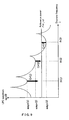
- Fig. 20 exemplifies a frequency spectrum of a voice.
- a frequency spectrum of a voice There is usually a plurality of peaks (showing relative maximum values) in the frequency spectrum of a voice, which are called formants.
- Fig. 20 exemplifies a spectrum with three formants (i.e., peaks), which are referred to as first, second and third formants from the lower frequency toward the higher frequency.
- the frequencies with relative maximum values that is, the frequency of each of the formants, fp(1), fp(2) and fp(3), is called a formant frequency.
- a frequency spectrum of a voice has the characteristic of the amplitude (i.e., power) decreasing with the frequency.
- the clarity of a voice is closely related with its formants, with an improved level of clarity possible by emphasizing the formants of higher levels (e.g., second and third formants).
- Fig. 21 exemplifies formant emphasis on a voice spectrum.
- the wave delineated by the solid line in Fig. 21 (a) , and the wave delineated by the dotted line in Fig. 21 (b) are voice spectra before an emphasis.
- the wave delineated by the solid line in Fig. 21 (b) shows a voice spectrum after emphasis.
- the straight line in the figure indicates the inclination of the spectrum.
- Fig. 22 shows a basic embodiment of the invention noted in the patent document 1 which relates to a technique using a band division filter.
- a spectrum estimation unit 160 figures out the spectrum of the input voice
- the convex/concave band decision unit 161 determines convex (i.e., peak) and concave (i.e., trough) bands based on the calculated spectrum and calculates an amplification ratio (or attenuation ratio) for the convex and concave bands.
- a filter configuration unit 162 provides a filter unit 163 with a coefficient for accomplishing the above described amplification ratio (or attenuation ratio) and inputs the input voice to the filter unit 163 for spectrum emphasis.
- the method noted by the patent document 1 being a method based on a band division filter, respectively amplifies and attenuates the peaks and troughs of the voice spectrum individually, thereby accomplishing emphasis of the voice.
- a voice decoding unit decodes an ABC vector, SCB vector and gains to generate a vocal source by using an ABC vector index, SCB vector index and gain index to generate a synthesis signal by filtering the voice source with a synthesis filter constituting an LPC decoded by the LPC index in the case of using the CELP method as presented by the seventh embodiment shown by Fig. 19 therein. Then the above described spectrum emphasis is accomplished by input of the synthesis signal and LPC to a spectrum emphasis unit.
- an embodiment of the invention proposed by patent document 2 being a voice signal processing apparatus applying to a post filter for a voice synthesis system comprised of a voice decoding apparatus for MBE (Multi-Band Excitation coding), is characterized by emphasizing the formants in the high frequencies of a frequency spectrum by maneuvering directly the amplitude value of each band as a parameter for frequency area.
- the formant emphasis method proposed in the patent document 2 is one estimating a band containing a formant based on the average amplitude of a plurality of frequency bands divided in accordance with a pitch frequency in the MBE method.
- an embodiment of the invention proposed by patent document 3 being an "analysis method by synthesis" with a reference signal which is a signal suppressing a noise gain, that is, a voice coding apparatus performing coding processing by using the A-b-S method, comprises a series of means for emphasizing the formant of the reference signal, dividing a signal into a voice component and a noise component and suppressing the level of the noise component.
- an LPC is extracted from the input signal frame by frame and the above described formant emphasis is applied based on the LPC.
- an embodiment of the invention proposed by patent document 4 relates to a vocal source search (i.e., multi-pass search) for multi-pass voice coding, that is, aiming to improve the compression efficiency by searching a vocal source after emphasizing the voice in the linear spectrum, instead of searching the vocal source by using the input voice as is when searching the vocal source information through approximating by multi-pass.
- a vocal source search i.e., multi-pass search
- the patent document 1 shows an example method in the seventh embodiment shown by Fig. 7 therein to accomplish spectrum emphasis by the input of a synthesis signal and LPC to the spectrum emphasis unit, corresponding to the case of using the CELP method.
- a vocal source signal is different from a vocal tract characteristic as understood by the above described voice generationmodel.
- the method noted by the patent document 1 makes it possible for a synthesized voice be emphasized by the emphasis filter obtained from the vocal tract characteristic, causing an enlarged distortion of the vocal source signal contained by the synthesized voice, sometimes resulting in side effects such as an increased sense of noise and a degraded clarity.
- an embodiment of the invention proposed by the patent document 2 aims at improving the quality of voice reproduced by an MBE vocoder (i.e., voice coder) as described above.
- MBE vocoder i.e., voice coder
- the mainstream technique of voice compression systems used for mobile phone systems, VoIP, video conference systems, et cetera is based on the CELP algorithm using linear prediction. Therefore, an application of the technique noted by the patent document 2 is faced with the problem of further degradation of voice quality because the coding parameters for the MBE vocoder are extracted from a degraded quality of voice having been compressed and decompressed.
- an embodiment of the invention proposed by the patent document 3 makes it possible for a simple IIR filter using an LPC for emphasizing the formant, which is known as emphasizing the formant erroneously through a published research paper (e.g., Acoustical Society of Japan: Lecture Papers; published in March 2000; pp. 249 and 250 ), et cetera.
- an embodiment of the invention proposed by the patent document 3 basically relates to a voice coding apparatus instead of a voice decoding apparatus.
- the challenge of embodiment of the present invention is to provide a speech decoder, a speech decoding method, the program thereof and a storage media for suppressing side effects of formant emphasis such as a degradation of voice quality and an increased sense of noisiness, and improving the clarity of reproduced voice and easy hearing of the receiving voice in equipment (e.g., mobile phone) using a speech coding method of an analysis-synthesis system.
- EP 1 557 827 A1 discloses a voice intensifier capable of reducing abrupt changes in the amplification factor between frames and realizing excellent sound quality with less noise feeling by dividing input voices into the sound source characteristic and the vocal tract characteristic, so as to individually intensify the sound source characteristic and the vocal tract characteristic and then synthesize them before being output.
- the voice intensifier comprises a signal separation unit for separating the input sound signal into the sound source characteristic and the vocal tract characteristic, a characteristic extraction unit for extracting characteristic information from the vocal tract characteristic, a corrective vocal tract characteristic calculation unit for obtaining vocal tract characteristic correction information from the vocal tract characteristic and the characteristic information, a vocal tract characteristic correction unit for correcting the vocal tract characteristic by using the vocal tract characteristic correction information, and a signal synthesizing means for synthesizing the corrective vocal tract characteristic from the vocal tract characteristic correction unit and the sound source characteristic, so that the sound synthesized by the signal synthesizing means is output.
- EP 1 557 827 A1 claims priority from JP 02/11332 which is discussed at the end of the description.
- EP 0 731 449 A2 discloses a CELP coding scheme, wherein p-order LPC coefficients of an input signal are transformed into n-order LPC cepctrum coefficients, which are modified into n-order modified LPC cepstrum coefficients.
- Log power spectral envelopes of the input signal and a masking function suited thereto are calculated, then they are subjected to inverse Fourier transform to obtain n-order LPC cepstrum coefficients, respectively, then the relationship between each corresponding orders of the both LPC cepstrum coefficients is calculated, and the modification in a step is carried out on the basis of the relationship.
- the modified coefficients are inversely transformed by the method of least squares into m-order LPC coefficients for use as filter coefficients of a perceptual weighting filter. This concept is applicable to a postfilter as well.
- US 6 098 036 A discloses a speech coding system and associated method which rely on a speech encoder and a speech decoder.
- the speech decoder includes a Linear Predictive Coding (LPC) filter having an input and an output.
- LPC filter provides synthesized speech at the output in response to voiced and unvoiced excitation provided at the input.
- a harmonic generator for providing voiced excitation to the input of the LPC filter includes a spectral formant enhancer for attenuating the amplitude of harmonics generate by the harmonic generator in spectral valleys between format peaks of respective frames of voiced speech.
- the system and method reduce perceived buzziness while increasing perceived spectral depth of synthesized speech at the output of the LPC filter.
- US 6 003 000 A discloses a method and system for representing speech with greatly reduced harmonic and intermodulation distortion using a fixed interval scale, known as Tru-Scale. Speech is reproduced in accordance with a frequency matrix which reduces intermodulation interference and harmonic distortion (overtone collision). Enhanced speech quality and reduced noise results from increasing the signal-to-noise ratio in the processed speech signal.
- the method and system use an Auto-Regressive (AR) modeling technique, using, among other approaches, Linear Predictive Coding (LPC) analysis.
- LPC Linear Predictive Coding
- a Fourier transform-based modeling technique also is used.
- the application of the system to speech coders also is contemplated.
- EP 0 742 548 A2 discloses a speech modification or enhancement filter, and apparatus, system and method using the same.
- Synthesized speech signals are filtered to generate modified synthesized speech signals.
- a filter coefficient is determined so as to ensure that formant characteristics of the modified synthesized speech signals are enhanced in comparison with those of the synthesized speech signal and in accordance with the spectral information.
- the spectral information can be any one of LSP information, PARCOR information and LAR information.
- a degree of freedom of design of the speech modification filter used for the aural suppression of quantizing noise contained in the synthesized speech signals is thus heightened leading to the improvement of intelligibility of said synthesized speech signals.
- a good formant enhancement effect can be obtained without allowing any perceptible level of distortions to occur within a range of permissible spectral gradients.
- JP 09081192 discloses a pitch emphasizing device which can suppress disorder in harmonics and improve the subjective quality even in the case where the pitch period varies greatly or is not correctly detected.
- a postfilter which includes a pitch emphasizing filter for improving the subjective quality of voice signals obtained by passing the coded data of voice signals through a parameter decoding section and a voice reproducing section has a pitch control section. This section is used to detect the change with time of the pitch period decoded at a parameter decoding section and to control the filter factor of the filter so that, based on this change, the extent of pitch emphasis for voice signals is changed.
- a speech decoder in the speech decoder comprised by a communication apparatus using a voice coding method in an analysis-synthesis system, comprises a code separation/decoding unit for restoring a vocal tract characteristic and a vocal source signal by separating a received voice code; a vocal tract characteristic modification unit for modifying the vocal tract characteristic; and a signal synthesis unit for outputting a voice signal by synthesizing the modified vocal tract characteristic modified by the vocal tract characteristic modification unit and the vocal source signal obtained from the voice code.
- the above configured speech decoder in the speech decoder comprised by a communication apparatus such as a mobile phone using a voice coding method in an analysis-synthes is system, having received a voice code transmitted following an application of voice coding processing thereto, restores a vocal tract characteristic and vocal source signal from the voice code, applies formant emphasis processing to the restored vocal tract characteristic to synthesize with the vocal source signal to output when generating a voice based on the voice code.
- the vocal tract characteristic is a linear predictor spectrum calculated based on a first linear predictor coefficient decoded from the voice code; the vocal tract characteristic modification unit applies a formant emphasis to the linear predictor spectrum; and the signal synthesis unit comprises a modified linear predictor coefficient calculation unit for calculating a second linear predictor coefficient corresponding to the formant emphasized linear predictor spectrum and a synthesis filter configured by the second linear predictor coefficients, and generates the voice signal to output by inputting the vocal source signal into the synthesis filter.
- an alternative embodiment may be such that, for instance, the vocal tract characteristic modification unit applies formant emphasis processing to the vocal tract characteristic and attenuation processing to an anti-formant, and generates a vocal tract characteristic emphasizing the amplitude difference between a formant and an anti-formant, and the signal synthesis unit synthesizes the vocal source signal based on the emphasized vocal tract characteristic.
- the above described embodiment makes it possible to emphasize the formant more to further improve voice clarity. Attenuating the anti-formant suppresses a sense of noisiness that tends to be accompanied by a decoded voice after the application of voice coding. That is, a voice which is coded and then decoded by a voice coding method such as the CELP as one thereof in an analysis-synthesis system is known to tend to accompany a noise called quantization noise to the anti-formant . Contrarily in embodiments of the present invention, the above described configuration attenuates the anti-formant, thereby reducing the above described quantized noise and accordingly providing a voice with little sense of noisiness and that can easily be heard.
- an alternative embodiment may further comprise, for instance, a pitch emphasis unit for applying pitch emphasis to the vocal source signal, wherein the signal synthesis unit synthesizes the pitch emphasized vocal source signal and the modified vocal tract characteristic to generate and output a voice signal.
- the above described embodiment restores a vocal source characteristic (i.e., residual differential signal) and a vocal tract characteristic by separating an input voice code and applies the appropriate emphasis processes to the respective characteristics, that is, emphasizing a pitch cyclicality of the vocal source characteristic and a formant emphasis of the vocal tract characteristic, thereby making it possible to further improve output voice clarity.
- a vocal source characteristic i.e., residual differential signal
- a vocal tract characteristic by separating an input voice code and applies the appropriate emphasis processes to the respective characteristics, that is, emphasizing a pitch cyclicality of the vocal source characteristic and a formant emphasis of the vocal tract characteristic, thereby making it possible to further improve output voice clarity.
- Fig. 1 illustrates a summary configuration of a speech decoder of the present embodiment.
- the speech decoder 10 comprises a code separation/decoding unit 11, a vocal tract characteristic modification unit 12 and a signal synthesis unit 13 as an overview configuration.
- the code separation/decoding unit 11 restores a vocal tract characteristic sp 1 and a vocal source signal r 1 from a voice code code (N.B: the last "code” herein denotes a component name).
- a CELP coder (not shown) comprised by a mobile phone, et cetera, separates an input voice into LPCs (Linear Prediction Coefficients) and a vocal source signal (i.e., residual differential signal), codes them respectively and multiplexes them for transmission to the receiving decoder comprised by a mobile phone, et cetera, as a voice code code.
- the decoder receives the voice code code, and the code separation/decoding unit 11 decode the vocal tract characteristic sp 1 and the vocal source signal r 1 from the voice code code as described above. Then, the vocal tract characteristic modification unit 12 modifies the vocal tract characteristic sp 1 to output a modified vocal tract characteristic sp 2 . This means generating and outputting an emphasized vocal tract characteristic sp 2 by directly applying formant emphasis processing to the vocal tract characteristic sp 1 for example.
- the signal synthesis unit 13 synthesizes the modified vocal tract characteristic sp 2 and the vocal source signal r 1 to generate and output an output voice, s, such as an output voice, s, with formant emphasis.
- a synthesized signal i.e., synthesized voice
- a restored vocal source signal i.e., output by the adder
- the synthesized voice is emphasized by an emphasis filter determined by a vocal tract characteristic. Therefore, the distortion of the vocal source signal contained in the synthesized voice increases, sometimes creating problems such as an increased sense of noisiness and a degradation of clarity.
- the speech decoder 10 though the processing from the beginning until restoring a vocal source signal and LPC is approximately the same as above, in contrast applies formant emphasis processing directly to the vocal tract characteristic sp 1 and synthesizes the emphasized vocal tract characteristic sp 2 and the vocal source signal (i.e., residual differential signal), without generating synthesized signal (synthesized voice). Therefore, the above described problem is solved, making it possible to achieve a decoded voice without causing side effects such as degraded voice quality by emphasis or an increased sense of noisiness.
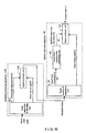
- Fig. 2 shows the basic configuration of a speech decoder of the present embodiment.
- CELP Code Excited Linear Prediction
- a speech decoder 20 shown by Fig. 2 comprises a code separation unit 21, an ACB vector decoding unit 22, an SCB vector decoding unit 23, a gain decoding unit 24, a vocal source signal generation unit 25, an LPC decoding unit 26, an LPC spectrum calculation unit 27, a spectrum emphasis unit 28, a modified LPC calculation unit 29 and a synthesis filter 30.
- the code separation unit 21, LPC decoding unit 26, ACB vector decoding unit 22, SCB vector decoding unit 23 and gain decoding unit 24 correspond to an example of a detailed configuration of the above described code separation/decoding unit 11.
- the spectrum emphasis unit 28 is an example of the above described vocal tract characteristic modification unit 12.
- the modified LPC calculation unit 29 and synthesis filter 30 correspond to an example of the above described signal synthesis unit 13.
- the code separation unit 21 outputs an LPC, ACB, SCB and gain codes by separating them from the voice code code transmitted from the transmitter following multiplexing thereby.
- the ACB vector decoding unit 22, SCB vector decoding unit 23 and gain decoding unit 24 respectively decode the ACB, SCB and gain codes output by the above described code separation unit 21 to gain theACB vector, SCB vector, and the ACB and SCB gains, respectively.
- the vocal source signal generation unit 25 generates vocal source signals (i.e., residual differential signal) r(n), where 0 ⁇ n ⁇ N, and N is a frame length in the coding method based on the above described ACB vector, SCB vector and the ACB and the SCB gains.
- vocal source signals i.e., residual differential signal
- the LPC decoding unit 26 decodes the LPC code output by the above described code separation unit 21 to gain LPC ⁇ 1 (i), where 1 ⁇ i ⁇ NP 1 , and outputs them to the LPC spectrum calculation unit 27, where NP 1 is the order of the LPC.
- the LPC spectrum calculation unit 27 calculates LPC spectra sp 1 ( l ), where 0 ⁇ l ⁇ N F , which is a parameter expressing a vocal tract characteristics from the input LPC ⁇ 1 (i). Note that N F is a spectrum mark that satisfies N ⁇ N F .
- the LPC spectrum calculation unit 27 outputs the calculated LPC spectrum sp 1 ( l ) to the spectrum emphasis unit 28.
- the spectrum emphasis unit 28 calculates the emphasized LPC spectra sp 2 ( l ) based on the LPC spectra sp 1 ( l ) to output to the modified LPC calculation unit 29.
- the modified LPC calculation unit 29 calculates the modified LPC ⁇ 2 (i), where 1 ⁇ i ⁇ NP 2 , based on the emphasized LPC spectra sp 2 ( l ).
- NP 2 is the order of the modified LPC.
- the modified LPC calculation unit 29 outputs the calculated modified LPC ⁇ 2 to the synthesis filter 30.
- the present embodiment applies a formant emphasis directly to the vocal tract characteristic (i.e., LPC spectrum calculated from the LPC) calculated from the voice code for emphasizing the vocal tract characteristic, followed by synthesis with the vocal source signal, making it possible avoid the problems of the conventional technique, that is, "a distortion of vocal source signal caused by an emphasis by using the emphasis filter obtained from the vocal tract characteristic.”
- the vocal tract characteristic i.e., LPC spectrum calculated from the LPC
- Fig. 3 shows a structural block diagram of a speech decoder 40 according to a first embodiment.
- Fig. 3 components that are approximately the same in configuration as those of the speech decoder 20 shown by Fig. 2 are assigned the same component numbers.
- CELP method is used for the voice coding method in the present embodiment, but it is not limited as such and, rather, any voice coding method in the analysis-synthesis system may be applied.
- the code separation unit 21 separates the voice code code into LPC, ACB, SCB codes and a gain code.
- the ACB vector decoding unit 22 decodes the above noted ACB code to obtain the ACB vectors p(n), where 0 ⁇ n ⁇ N, and N is the frame length of the coding method.
- the SCB vector decoding unit 23 decodes the above noted SCB code to obtain the SCB vectors c(n), where 0 ⁇ n ⁇ N.
- the gain decoding unit 24 decodes the above noted gain code to obtain the ACB gain g p and the SCB gain g c .
- the LPC decoding unit 26 decodes the LPC separated by and output by the above described code separation unit 21 to obtain the LPC ⁇ 1 (i), where 1 ⁇ i ⁇ NP 1 , and NP 1 denotes the order of LPC, and sends it to the LPC spectrum calculation unit 27.
- the LPC spectrum calculation unit 27 obtains the LPC spectra sp 1 ( l ) as the vocal tract characteristic by calculating the Fourier transformation of the LPC ⁇ 1 (i) by the following equation (2), where N F is the number of data points for the spectra; and P 1 is the order of the LPC filter. Letting the sampling frequency be F s , the frequency resolution of the LPC spectrum sp 1 ( l ) is F s /N F .
- the variable, l is the index of spectrum, indicating a discrete frequency.
- the variable l is converted to a frequency, by the equation int[ l *F s /N F ] (Hz), where the int [x] denotes the conversion of variable x to an integer.
- the LPC spectrum sp 1 (/) obtained by the LPC spectrum calculation unit 27 is input to a formant estimation unit 41, an amplification ratio calculation unit 42 and a spectrum emphasis unit 43.
- the formant estimation unit 41 receiving input of the LPC spectrum sp 1 ( l ), estimates the formant frequencies fp (k), where 1 ⁇ k ⁇ k max, and the amplitudes ampp(k), where 1 ⁇ k ⁇ kpmax.
- an example technique may be of a known technique such as the peak picking method for estimating a formant based on peaks of the frequency spectrum.
- a threshold value may be provided for the bandwidth of a formant so as to define frequencys with the bandwidth being no more than the threshold value formant frequencys.
- the amplification ratio calculation unit 42 calculates an amplification factor ⁇ ( l ) for the LPC spectra sp 1 ( l ) by input of the above described LPC spectra sp 1 ( l ) and the formant frequencies and amplitudes, ⁇ fp(k), ampp(k) ⁇ , estimated by the formant estimation unit 41.
- Fig. 4 shows a process flow chart for an amplification ratio calculation unit 42.
- the processes in the amplification ratio calculation unit 42 are, sequentially, a calculation of the reference power for amplification (step S11; simply noted “S11” hereinafter), a calculation of the amplification ratio of a formant (S12) and an interpolation of an amplification ratio (S13).
- the first description is of the processing of step S11, that is, for calculating the reference power for amplification, Pow_ref, based on the LPC spectrum sp 1 ( l ).
- the S12 determines formant amplification ratios Gp (k) so as to result in the formant amplitudes ampp (k), where 1 ⁇ k ⁇ kpmax, match with the amplification reference power, Pow_ref, obtained in S11.
- Fig. 5 shows how the formant amplitudes ampp(k) are matched with the amplification reference power, Pow_ref.
- Emphasizing the LPC spectrum by using the amplification ratios obtained as described above flattens the inclination of the entire spectrum, thereby improving the clarity of the voice across the whole spectrum.
- the S13 calculates an amplification ratio ⁇ ( l ) of the frequency band existing between the adj acent formants (i.e., between fp (k) and fp(k+1)) by an interpolation curve R(k, l ). While the form of the interpolation curve is discretionary, the following exemplifies the case of a quadratic interpolation curve R(k, l ).
- the emphasized spectrum sp 2 ( l ) obtained by the spectrum emphasis unit 43 is then input to the modified LPC calculation unit 29 which in turn calculates auto-correlation functions ac 2 (i) by applying an inverse Fourier transformation to the emphasized spectra sp 2 ( l ), followed by obtaining a modified LPC ⁇ 2 (i), where 1 ⁇ i ⁇ NP 2 from the auto-correlation functions ac 2 (i) by using a known method such as the Levinson algorithm, where the NP 2 is the order of the modified LPC.
- the synthesis filter 30 calculates an output voice s(n) by the following equation (11), by which the emphasized vocal tract characteristic and the vocal source characteristic are synthesized.
- a vocal tract characteristic decoded from a voice code is emphasized, followed by synthesizing it with a vocal source signal in the first embodiment.
- This suppresses the spectral distortion occurring when emphasizing the vocal tract characteristic and the vocal source signal simultaneously, as has been a problem with the conventional technique, thereby improving voice clarity.
- the present embodiment calculates amplification ratios for frequency components other than formants based on the amplification ratios for the formants and thereby applies the emphasis processing therefor, hence emphasizing the vocal tract characteristic smoothly.
- the spectrum may be divided into a plurality of frequency bands so as to obtain the respective amplification ratios for those frequency bands.
- Fig. 7 shows a structural block diagram of a speech decoder 50 according to a second embodiment.
- the second embodiment is characterized by attenuating anti-formants whose amplitudes take minimum values, in addition to emphasizing formants to emphasize the difference between formants and anti-formants. Note that the present embodiment assumes that an anti-formant only exists between two adjacent formants in the following description, but it is not limited as such and rather it is possible to apply the present embodiment to the case where an anti-formant exists in a lower frequency than the lowest order formant or in a higher frequency than the highest order formant.
- a speech decoder 50 shown by Fig. 7 comprises a formant/anti-formant estimation unit 51 and an amplification ratio calculation unit 52, which together replace the formant estimation unit 41 and amplification ratio calculation unit 42 comprised by the speech decoder 40 shown by Fig. 3 , while the other components are approximately the same as the speech decoder 40.
- the formant/anti-formant estimation unit 51 having received an LPC spectra sp 1 ( l ), estimates anti-formant frequencies fv(k), where 1 ⁇ k ⁇ kvmax, and the amplitudes ampv(k), where 1 ⁇ k ⁇ kvmax, in addition to formant frequencies fp(k), where 1 ⁇ k ⁇ kpmax, and the amplitudes ampp(k), where 1 ⁇ k ⁇ kpmax, the same as the above described formant estimation unit 41.
- an example method is to apply the peak picking method to the inverse number of spectra sp 1 ( l ), where the obtained anti-formants are defined sequentially from the lower order, as, fv(1), fv(2), ...fv(kvmax), kvmax is the number of anti-formants and ampv(k) is the amplitude at fv(k).
- the estimation result of the formants and anti-formants obtained by the formant/anti-formant estimation unit 51 is then input to the amplification ratio calculation unit 52.
- Fig. 8 shows a process flow chart for the amplification factor calculation unit 52.
- the processes of the amplification factor calculation unit 52 are performed in the order of calculating the reference power of formants for amplification (S21), determining amplification ratios of formants (S22), calculating the amplification reference power of anti-formants (S23), determining amplification ratios of anti-formants (S24) and interpolating amplification ratios (S25) as shown by Fig. 8 .
- the processings of S21 and S22 are the same as of the steps S11 and S12, respectively, and therefore the descriptions thereof are omitted herein.
- the first description is of a calculation of amplification reference powers of anti-formants in the step S23.
- the amplification reference power of anti-formant Pow_refv is calculated from the LPC spectra sp 1 ( l )
- the method being discretionary, there are examples of methods using the amplification reference power of formant Pow_ref multiplied by a constant less than one (1) and choosing the minimum amplitude as the reference power from among the anti-formant amplitudes ampv(k), where 1 ⁇ k ⁇ kvmax.
- Pow_refv ⁇ Pow_ref where ⁇ is a discretionary constant satisfying 0 ⁇ ⁇ ⁇ 1.
- Fig. 9 shows how amplification ratios of anti-formants Gv(k) are determined.
- step S24 determines the amplification ratios Gv (k) so as to match the anti-formant amplitudes ampv (k), where 1 ⁇ k ⁇ kvmax, with the amplification reference power of anti-formant Pow_refv obtained by the step S23.
- step S25 performs the interpolation processing for the amplification ratios.
- the method for obtaining the interpolation curve is discretionary.
- the equation (15) makes it possible to calculate the "a”, and obtain the quadratic curve R 1 (k, l ) and the interpolation curve R 2 (k, l ) between fv(k) and fp(k+1).
- the amplification ratio calculation unit 52 outputs the amplification ratios ⁇ ( l ) to the spectrum emphasis unit 43 which in turn calculates an emphasized spectra sp 2 ( l ) according to the above described equation (10) by using the amplification ratios ⁇ ( l ).
- the second embodiment attenuates anti-formants in addition to amplifying formants, thereby further emphasizing the formants relative to the anti-formants and further improving the clarity as compared to the first embodiment.
- Attenuating anti-formants makes it possible to suppress a sense of noisiness prone to accompany a decoded voice after voice coding processing.
- a voice coded and decoded by a voice coding method such as the CELP which is used for a mobile phone, et cetera is known to be accompanied by a noise called quantization noise in the anti-formants.
- Embodimetns of the present invention attenuate the anti-formants, thereby reducing the quantization noise and providing a voice that is easy to hear with little sense of noisiness.
- Fig. 10 shows a structural block diagram of a speech decoder 60 according to a third embodiment.
- the third embodiment is characterized by a configuration for applying a pitch emphasis on a vocal source signal in addition to that of the first embodiment, that is, by comprising a pitch emphasis filter configuration unit 62 and a pitch emphasis unit 63. Furthermore, an ACB vector decoding unit 61 not only decodes the ACB code to obtain ACB vectors p(n), where 0 ⁇ n ⁇ N, but also obtain the integer part T of pitch lag from the ACB code to output to the pitch emphasis filter configuration unit 62.
- the pitch emphasis unit 63 filters a vocal source signal r (n) by subjecting it to a pitch emphasis filter (i.e., a filter with the transfer function described by equation (17); g p as a weighting factor) configured by the pitch predictor coefficients pc(i) to output a residual differential signal (i.e., vocal source signal) r'(n).
- a pitch emphasis filter i.e., a filter with the transfer function described by equation (17); g p as a weighting factor
- the synthesis filter 30 substitutes the obtained vocal source signal r' (n), as described above, into the equation (11) in stead of the r(n) to obtain an output voice s(n).
- the present embodiment uses a three-tap IIR filter for the pitch emphasis filter, but it is not limited as such and rather it may be possible to change a tap length or use other discretionary filters such as FIR filters.
- the third embodiment emphasizes a pitch cycle component contained by a vocal source signal by further comprising a pitch emphasis filter in addition to the configuration of the first embodiment, thereby making it possible to improve voice clarity further as compared thereto. That is, restoring a vocal source characteristic (i.e., residual differential signal) and a vocal tract characteristic by separating an input voice code and applying emphasis processes respectively suitable thereto, i.e., emphasizing the pitch cyclicality for the vocal source characteristic while emphasizing formants for the vocal tract characteristics makes it possible to further improve the output voice clarity.
- a vocal source characteristic i.e., residual differential signal
- a vocal tract characteristic by separating an input voice code and applying emphasis processes respectively suitable thereto, i.e., emphasizing the pitch cyclicality for the vocal source characteristic while emphasizing formants for the vocal tract characteristics makes it possible to further improve the output voice clarity.
- Fig. 11 shows a hardware configuration of a mobile phone/PHS (i.e., Personal Handy-phone System) as one application of a speech decoder of the present embodiment.
- a mobile phone capable of performing discretionary processing by executing a program, et cetera, can be considered as a sort of computer.
- the mobile phone/PHS 70 shown by Fig. 11 comprises an antenna 71, a radio transmission unit 72, an AD/DA converter 73, a DSP (Digital Signal Processor) 74, a CPU 75, memory 76, a display unit 77, a speaker 78 and a microphone 79.
- AD/DA converter 73 AD/DA converter 73
- DSP Digital Signal Processor
- the DSP 74 executing a prescribed program stored in the memory 76 for a voice code code received by way of the antenna 71, radio transmission unit 72 and AD/DA converter 73 achieves the speech decoding processing described in reference to Figs. 1 through 10 to output an output voice.
- the application of the speech decoder according to embodiments of the present invention is in no way limited to the mobile phone, but may be VoIP (Voice over Internet Protocol) or a video conference system for example. That is, any kind of computer having the function of communicating by wired or wireless means by applying a voice coding method for compressing voice and capable of performing the speech decoding processing as described in reference to Figs. 1 through 10 .
- Fig. 12 exemplifies an overview of the hardware configuration of such a computer.
- the computer 80 shown by Fig. 12 comprises a CPU 81, memory 82, an input apparatus 83, an output apparatus 84, an external storage apparatus 85, a media drive apparatus 86, and a network connection apparatus 87, and a bus 88 connecting the aforementioned components.
- Fig. 12 exemplifies a generalized configuration that may vary.
- the memory 82 is memory such as RAM for temporarily storing a program or data stored in the external storage apparatus 85 (or a portable storage medium 89) when executing the program or renewing the data.
- the CPU 81 accomplishes the above described various processes and functions (i.e., the processes shown by Figs. 4 and 8 ; and the functions of the respective functional units shown by Figs. 1 through 3 , 7 and 10 ) by executing the program loaded into the memory 82.
- the input apparatus 83 comprises a keyboard, a mouse, a touch panel, a microphone, for example.
- the output apparatus 84 comprises a display and a speaker, for example.
- the external storage apparatus 85 comprises a magnetic disk, an optical disk and magneto optical disk apparatuses, stores the program and data, et cetera, for the speech decoder to accomplish the above described various functions.
- the media drive apparatus 86 reads out the program and data stored in the portable storage medium 89.
- the portable storage medium 89 comprises an FD (Flexible Disk), a CD-ROM, and other media such as a DVD, a magneto optical disk, for example.
- the network connection apparatus 87 is configured to enable the program and data exchanges with an external information processing apparatus by connecting with a network.
- Fig. 13 exemplifies a storage medium storing the above described program and downloading of the program.
- a configuration may be such that the program and data for accomplishing the functions of embodiments of the present invention are read from the portable storage medium 89 to the computer 80, stored in the memory and executed, or alternatively the aforementioned program and data stored in a storage unit 2 comprised by an external server 1 are downloaded through a network 3 (e.g., the Internet) by way of the network connection apparatus 87.
- a network 3 e.g., the Internet
- Embodiments of the present invention are not limited either by an apparatus or method, but it may be configured as a storage medium (e.g., portable storage media 89) per se storing the above described program and data, or as the above described program per se.
- a storage medium e.g., portable storage media 89
- Fig. 14 shows the basic configuration of speech emphasis apparatus 90 proposed by the prior patent application.
- the speech emphasis apparatus 90 shown by Fig. 14 is characterized in such a way that a signal analysis/separation unit 91 first analyzes an input voice, x, and separates it into a vocal source signal, r, and a vocal tract characteristic sp 1 ; a vocal tract characteristic modification unit 92 modifies the vocal tract characteristic sp 1 (e.g., formant emphasis) and outputs the modified (i.e., emphasized) vocal tract characteristic sp 2 ; and lastly a signal synthesis unit 93 re-synthesizes the vocal source signal, r, with the above described modified (i.e., emphasized) vocal tract characteristic sp 2 , thereby outputting a formant emphasized voice.
- a signal analysis/separation unit 91 first analyzes an input voice, x, and separates it into a vocal source signal, r, and a vocal tract characteristic sp 1 ; a vocal tract characteristic modification unit 92 modifies the vocal tract characteristic sp 1 (e
- the prior patent application separates an input voice into a vocal source signal, r, and a vocal tract characteristic sp 1 , followed by emphasizing the vocal tract characteristic, thereby avoiding the distortion of the vocal source signal that has been a problem associated with the method noted by the patent document 1. Therefore it is possible to apply formant emphasis without causing an increased sense of noisiness or decreased voice clarity.
- Fig. 15 exemplifies a configuration in the case of applying the speech emphasis apparatus presented by the prior patent application to a mobile phone, et cetera, equipped with a CELP decoder.
- the speech emphasis apparatus 90 noted by the prior patent application, receiving a voice, x, as described above, comprises a decoding processing apparatus 100 in the front stage thereof for decoding a voice code code transmitted from the outside in the decoding processing apparatus 100 to input the decoded voice, s, to the speech emphasis apparatus 90 as shown by Fig. 15 .
- a code separation/decoding unit 101 generates a vocal source signal r 1 and a vocal tract characteristic sp 1 from the voice code code and a signal synthesis unit 102 synthesize them to generates and outputs a decoded voice, s.
- the decoded voice, s has its information compressed and therefore the amount of information is reduced as compared to the voice prior to the coding and accordingly is of poor quality.
- the speech emphasis apparatus 90 re-analyzes the voice of a degraded quality to separate a vocal source signal and a vocal tract characteristic. This then causes a degraded separation accuracy, sometimes resulting in a vocal source signal component remaining in a vocal tract characteristic sp 1 ' which is separated from the decoded voice, s, or a vocal tract characteristic which remains in a vocal source signal r 1 '. Therefore, there is a possibility of emphasizing a vocal source signal component remaining in the vocal tract characteristic, or failing to emphasize a vocal tract characteristic remaining in the vocal source signal, when the vocal tract characteristic is emphasized. This in turn has made it possible to degrade the quality of output voice s' having been re-synthesized from the vocal source signal and the formant emphasized vocal tract characteristic.
- the speech decoder uses a vocal tract characteristic decoded from a voice code, eliminating the case of quality degradation due to a re-analysis of a degraded voice. Furthermore, an elimination of re-analysis makes it possible to reduce the processing load.
- the speech decoder, decoding method and the program in a communication apparatus such as mobile phone using a voice coding method in an analysis-synthesis system, having received a voice code which has been processed with a voice coding prior to the transmission, restores a vocal tract characteristic and a vocal source signal from the voice code, applies formant emphasis to the restored vocal tract characteristic to synthesize it with the vocal source signal when generating and outputting a voice based on the voice code.
- This suppresses distortion of the spectrum occurring when a vocal tract characteristic and a vocal source signal are simultaneously emphasized that has been a problem with the conventional technique, thereby making it possible to improve the clarity. That is, it is possible to decode a voice without causing a second effect such as a degradation of voice quality or an increased sense of noisiness, enabling ease of hearing with improved voice clarity.
Landscapes
- Engineering & Computer Science (AREA)
- Computational Linguistics (AREA)
- Signal Processing (AREA)
- Health & Medical Sciences (AREA)
- Audiology, Speech & Language Pathology (AREA)
- Human Computer Interaction (AREA)
- Physics & Mathematics (AREA)
- Acoustics & Sound (AREA)
- Multimedia (AREA)
- Quality & Reliability (AREA)
- Compression, Expansion, Code Conversion, And Decoders (AREA)
Description
- The present invention relates to a communication apparatus such as a mobile phone communicating through speech coding processing, particularly a speech decoder, speech decoding method, et cetera, comprised by the communication apparatus to improve voice clarity for ease of hearing of the received voice.
- Mobile phones have become widely spread in recent years. In mobile phone systems, speech coding techniques are used for compressing the voice in order to better utilize communication lines. Among such speech coding techniques, the CELP (Code Excited Linear Prediction) system is known as a coding method for providing good voice quality at a low bit rate and the CELP-based coding method is adopted by many voice coding standards such as ITU-T G. 729 system, 3GPP AMR system, et cetera. The CELP algorithm-based method is also the most commonly used technique for voice compression used for VoIP (Voice over Internet Protocol), video conference system, et cetera, and is not limited to the mobile phone system.
- Here, CELP is summarized. A speech coding method introduced by Messrs. M.R. Schroder and B.S. Atal in 1985, the CELP extracts parameters from the input voice based on a human voice creation model for transmitting the parameters through coding, thereby accomplishing highly efficient information compression.
-
Fig. 16 shows a voice creationmodel, in the process of which a vocal source signal generated by a vocal source (i.e., vocal chords) 110 is input to an articulatory system (i.e., vocal tract) 111, where a vocal tract characteristic is added, and a voice wave is finally output from the lips 112 (refer to the non-patent document 1). That is, the voice is made up of vocal source and vocal tract characteristics. -
Fig. 17 shows the process flow of CELP coding and decoding. -
Fig. 17 shows how a CELP coder and decoder are equipped in a mobile phone for example, and a voice signal (i.e., voice code code) is transmitted from theCELP coder 120 equipped in the transmitting mobile phone to the CELPdecoder 130 equipped in the receiving mobile phone by way of a transmission path (not-shown; e.g., wireless communication line, mobile phone network, et cetera). - In the
CELP coder 120 equipped in the transmitting mobile phone, aparameter extraction unit 121 analyzes the input voice based on the above mentioned voice generation model to separate the input voice into LPC (Linear Predictor Coefficients) indicating the vocal tract characteristics and a vocal source signal. Theparameter extraction unit 121 further extracts an ACB (Adaptive CodeBook) vector indicating a cyclical component of the vocal source signal, an SCB (Stochastic CodeBook) vector indicating a non-cyclical component thereof, and a gain of each vector. - Then a
coding unit 122 codes the LPC, ACB vector, SCB vector and the gain to generate the LPC code, ACB code, SCB code and gain code so that acode multiplexer unit 123 multiplexes them to generate a voice code code to transmit to the receiving mobile phone. - In the CELP
decoder 130 equipped in the receiving mobile phone, acode separation unit 131 first separates the transmitted voice code code into the LPC code, ACB code, SCB code and gain code so that adecoder 132 decodes them to the LPC, ACB vector, SCB vector and gain, respectively. Then avoice synthesis unit 133 synthesizes a voice according to the decoded parameters. - The following detailed descriptions are of the CELP coder and the CELP decoder.
-
Fig. 18 is a block diagram ofparameter extraction unit 121 equipped in the CELP coder. - In the CELP, an input voice is coded in the unit of frames of a certain length. First, an
LPC analysis unit 141 calculates an LPC from the input voice according to a known LPC (Linear Prediction Coefficients) analysis method. The LPC is a filter coefficient when a vocal tract characteristic is approximated by an all pole linear filter. - Next, extracts a vocal source signal by using an AbS (Analysis by Synthesis) method. In the CELP, a voice is reproduced by inputting a vocal source signal to an
LPC synthesis filter 142 constituted by the LPC. Therefore, a differentialpower evaluation unit 145 searches a combination of the CodeBooks where a differential error with the input voice becomes a minimum when a voice is synthesized by theLPC synthesis filter 142 from among the voice source candidates constituted by combinations among a plurality of ACB vectors stored in anACB 143, a plurality of SCB vectors stored in anSCB 144 and the gains of the aforementioned two vectors to extract an ACB vector, SCB vector, ACB gain and SCB gain. - As described above, the
coding unit 122 codes each parameter extracted by the above described operation to obtain an LPC code, ACB code, SCB code and gain code. Thecode multiplexer unit 123 multiplies each obtained code to transmit to the decoding side as a voice code code. - The next description is of the CELP decoder in further detail.
-
Fig. 19 shows a block diagram of theCELP decoder 130. - In the CELP decoder, the
code separation unit 131 separates each parameter from the transmitted voice code code as described above to obtain an LPC code, an ACB code, an SCB code and a gain code. - Next, an
LPC decoder 151,ACB vector decoder 152,SCB vector decoder 153 andgain decoder 154 all constituting thedecoding unit 132 respectively decode the LPC code, the ACB code, the SCB code and the gain code to obtain an LPC, an ACB vector, an SCB vector and the gains (i.e., ACB gain and SCB gain), respectively. - The
voice synthesis unit 133 generates a vocal source signal from the input ACB vector, SCB vector and the gains (i.e., ACB gain and SCB gain) by the shown configuration, and inputs the vocal source signal into theLPC synthesis filter 155 structured by the above described decoded LPC to thereby decode and output a voice. - Incidentally, a mobile phone is often used not only in a quiet place but also in a noisy environment surrounded by noise such as an airport or the platform of a railway station. In such a case the remote user is faced with a problem of difficulty in hearing the received voice impaired by the ambient noise. Not only that, in a video conference system for instance, which is usually used at home the user is surrounded by background noises such as those emitted by electric appliances such as air conditioners and the noise of the activity of people nearby.
- As a countermeasure to such problems there are several known techniques to improve a received voice by improving clarity thereof by emphasizing the formants of the frequency spectrum of the receiving voice,
- The following is a brief description of formants.
-
Fig. 20 exemplifies a frequency spectrum of a voice. - There is usually a plurality of peaks (showing relative maximum values) in the frequency spectrum of a voice, which are called formants.
Fig. 20 exemplifies a spectrum with three formants (i.e., peaks), which are referred to as first, second and third formants from the lower frequency toward the higher frequency. The frequencies with relative maximum values, that is, the frequency of each of the formants, fp(1), fp(2) and fp(3), is called a formant frequency. Generally speaking, a frequency spectrum of a voice has the characteristic of the amplitude (i.e., power) decreasing with the frequency. Furthermore, it is known that the clarity of a voice is closely related with its formants, with an improved level of clarity possible by emphasizing the formants of higher levels (e.g., second and third formants). -
Fig. 21 exemplifies formant emphasis on a voice spectrum. - The wave delineated by the solid line in
Fig. 21 (a) , and the wave delineated by the dotted line inFig. 21 (b) are voice spectra before an emphasis. The wave delineated by the solid line inFig. 21 (b) shows a voice spectrum after emphasis. The straight line in the figure indicates the inclination of the spectrum. - It is known that emphasizing the voice spectrum so as to increase the amplitude of higher level formants, flattening the inclination of whole spectrum as shown by
Fig. 21 (b) , improves the clarity of entire voice. - The, following techniques are known as such formant emphasis techniques.
- The technique noted by the
patent document 1 is an example of applying formant emphasis to a coded voice. -
Fig. 22 shows a basic embodiment of the invention noted in thepatent document 1 which relates to a technique using a band division filter. As understood byFig. 22 , in the technique noted by thepatent document 1, aspectrum estimation unit 160 figures out the spectrum of the input voice, and the convex/concaveband decision unit 161 determines convex (i.e., peak) and concave (i.e., trough) bands based on the calculated spectrum and calculates an amplification ratio (or attenuation ratio) for the convex and concave bands. - Then, a
filter configuration unit 162 provides afilter unit 163 with a coefficient for accomplishing the above described amplification ratio (or attenuation ratio) and inputs the input voice to thefilter unit 163 for spectrum emphasis. - There has been a problem of emphasizing components other than the formants resulting in a degraded clarity, associated with the method using the band division filter because there has conventionally been no guarantee that a voice formant will be included in each frequency band.
- Contrarily, the method noted by the
patent document 1, being a method based on a band division filter, respectively amplifies and attenuates the peaks and troughs of the voice spectrum individually, thereby accomplishing emphasis of the voice. - Furthermore in the
patent document 1, a voice decoding unit decodes an ABC vector, SCB vector and gains to generate a vocal source by using an ABC vector index, SCB vector index and gain index to generate a synthesis signal by filtering the voice source with a synthesis filter constituting an LPC decoded by the LPC index in the case of using the CELP method as presented by the seventh embodiment shown byFig. 19 therein. Then the above described spectrum emphasis is accomplished by input of the synthesis signal and LPC to a spectrum emphasis unit. - Meanwhile, an embodiment of the invention proposed by
patent document 2, being a voice signal processing apparatus applying to a post filter for a voice synthesis system comprised of a voice decoding apparatus for MBE (Multi-Band Excitation coding), is characterized by emphasizing the formants in the high frequencies of a frequency spectrum by maneuvering directly the amplitude value of each band as a parameter for frequency area. The formant emphasis method proposed in thepatent document 2 is one estimating a band containing a formant based on the average amplitude of a plurality of frequency bands divided in accordance with a pitch frequency in the MBE method. - Meanwhile, an embodiment of the invention proposed by
patent document 3, being an "analysis method by synthesis" with a reference signal which is a signal suppressing a noise gain, that is, a voice coding apparatus performing coding processing by using the A-b-S method, comprises a series of means for emphasizing the formant of the reference signal, dividing a signal into a voice component and a noise component and suppressing the level of the noise component. In the processing, an LPC is extracted from the input signal frame by frame and the above described formant emphasis is applied based on the LPC. - Meanwhile, an embodiment of the invention proposed by
patent document 4 relates to a vocal source search (i.e., multi-pass search) for multi-pass voice coding, that is, aiming to improve the compression efficiency by searching a vocal source after emphasizing the voice in the linear spectrum, instead of searching the vocal source by using the input voice as is when searching the vocal source information through approximating by multi-pass. - [Patent document 1] Japanese unexamined patent application publication No.
2001-117573 - [Patent document 2] Japanese unexamined patent application publication No.
6-202695 - [Patent document 3] Japanese unexamined patent application publication No.
8-272394 - [Patent document 4] Japanese registered patent No.
7-38118 - [Non-patent document 1] "High efficiency coding of voice" authored by Kazuo Nakata pp. 69 through 71; published by Morikita Shuppan Co., Ltd.
- The above noted conventional techniques are faced with problems respectively as described in the following.
- First of all, the method noted in the
patent document 1 is faced with the following problem. - As noted above, the
patent document 1 shows an example method in the seventh embodiment shown byFig. 7 therein to accomplish spectrum emphasis by the input of a synthesis signal and LPC to the spectrum emphasis unit, corresponding to the case of using the CELP method. A vocal source signal, however, is different from a vocal tract characteristic as understood by the above described voice generationmodel. The difference notwithstanding, the method noted by thepatent document 1 makes it possible for a synthesized voice be emphasized by the emphasis filter obtained from the vocal tract characteristic, causing an enlarged distortion of the vocal source signal contained by the synthesized voice, sometimes resulting in side effects such as an increased sense of noise and a degraded clarity. - Meanwhile, an embodiment of the invention proposed by the
patent document 2 aims at improving the quality of voice reproduced by an MBE vocoder (i.e., voice coder) as described above. Currently the mainstream technique of voice compression systems used for mobile phone systems, VoIP, video conference systems, et cetera, is based on the CELP algorithm using linear prediction. Therefore, an application of the technique noted by thepatent document 2 is faced with the problem of further degradation of voice quality because the coding parameters for the MBE vocoder are extracted from a degraded quality of voice having been compressed and decompressed. - Meanwhile, an embodiment of the invention proposed by the
patent document 3 makes it possible for a simple IIR filter using an LPC for emphasizing the formant, which is known as emphasizing the formant erroneously through a published research paper (e.g., Acoustical Society of Japan: Lecture Papers; published in March 2000; pp. 249 and 250), et cetera. In addition, an embodiment of the invention proposed by thepatent document 3 basically relates to a voice coding apparatus instead of a voice decoding apparatus. - Meanwhile, and embodiment of the invention proposed by the
patent document 4 aims at improving the efficiency of compression by searching a vocal source and specif ically, when searching voice information through approximation by multi-pass, by searching the vocal source after emphasizing the voice in a linear spectrum instead of using the input voice as is, not aiming at clarity of voice. - The challenge of embodiment of the present invention is to provide a speech decoder, a speech decoding method, the program thereof and a storage media for suppressing side effects of formant emphasis such as a degradation of voice quality and an increased sense of noisiness, and improving the clarity of reproduced voice and easy hearing of the receiving voice in equipment (e.g., mobile phone) using a speech coding method of an analysis-synthesis system.
-
EP 1 557 827 A1EP 1 557 827 A1JP 02/11332 -
EP 0 731 449 A2 discloses a CELP coding scheme, wherein p-order LPC coefficients of an input signal are transformed into n-order LPC cepctrum coefficients, which are modified into n-order modified LPC cepstrum coefficients. Log power spectral envelopes of the input signal and a masking function suited thereto are calculated, then they are subjected to inverse Fourier transform to obtain n-order LPC cepstrum coefficients, respectively, then the relationship between each corresponding orders of the both LPC cepstrum coefficients is calculated, and the modification in a step is carried out on the basis of the relationship. The modified coefficients are inversely transformed by the method of least squares into m-order LPC coefficients for use as filter coefficients of a perceptual weighting filter. This concept is applicable to a postfilter as well. -
US 6 098 036 A discloses a speech coding system and associated method which rely on a speech encoder and a speech decoder. The speech decoder includes a Linear Predictive Coding (LPC) filter having an input and an output. The LPC filter provides synthesized speech at the output in response to voiced and unvoiced excitation provided at the input. A harmonic generator for providing voiced excitation to the input of the LPC filter includes a spectral formant enhancer for attenuating the amplitude of harmonics generate by the harmonic generator in spectral valleys between format peaks of respective frames of voiced speech. The system and method reduce perceived buzziness while increasing perceived spectral depth of synthesized speech at the output of the LPC filter. -
US 6 003 000 A discloses a method and system for representing speech with greatly reduced harmonic and intermodulation distortion using a fixed interval scale, known as Tru-Scale. Speech is reproduced in accordance with a frequency matrix which reduces intermodulation interference and harmonic distortion (overtone collision). Enhanced speech quality and reduced noise results from increasing the signal-to-noise ratio in the processed speech signal. The method and system use an Auto-Regressive (AR) modeling technique, using, among other approaches, Linear Predictive Coding (LPC) analysis. In accordance with another aspect of the invention, a Fourier transform-based modeling technique also is used. The application of the system to speech coders also is contemplated. -
EP 0 742 548 A2 discloses a speech modification or enhancement filter, and apparatus, system and method using the same. Synthesized speech signals are filtered to generate modified synthesized speech signals. From spectral information represented as a multi-dimensional vector, a filter coefficient is determined so as to ensure that formant characteristics of the modified synthesized speech signals are enhanced in comparison with those of the synthesized speech signal and in accordance with the spectral information. The spectral information can be any one of LSP information, PARCOR information and LAR information. A degree of freedom of design of the speech modification filter used for the aural suppression of quantizing noise contained in the synthesized speech signals is thus heightened leading to the improvement of intelligibility of said synthesized speech signals. A good formant enhancement effect can be obtained without allowing any perceptible level of distortions to occur within a range of permissible spectral gradients. -
JP 09081192 - According to a first aspect of the invention, there is provided a speech decoder as recited in
Claim 1. - According to a second aspect of the invention, there is provided a speech decoding method as recited in Claim 8.
- According to a third aspect of the invention, there is provided a program for a computer as recited in
Claim 10. - According to a fourth aspect of the invention, there is provided a computer readable storage medium as recited in
Claim 12. - Embodiments of the present invention will be more apparent from the following detailed description when the accompanying drawings are referred to.
-
Fig. 1 illustrates an overview configuration of speech decoder of the present embodiment; -
Fig. 2 shows the basic configuration of a speech decoder of the present embodiment; -
Fig. 3 shows a structural block diagram ofspeech decoder 40 according to a first embodiment; -
Fig. 4 shows a process flow chart of an amplification ratio calculation unit; -
Fig. 5 shows how an amplification ratio of a formant is calculated; -
Fig. 6 exemplifies an interpolation curve; -
Fig. 7 shows a structural block diagram of a speech decoder according to a second embodiment; -
Fig. 8 shows a process flow chart for an amplification ratio calculation unit; -
Fig. 9 shows how amplification ratios of anti-formants are determined; -
Fig. 10 shows a structural block diagram of speech decoder according to a third embodiment; -
Fig. 11 shows a hardware configuration of a mobile phone as one of the applications of a speech decoder; -
Fig. 12 shows a hardware configurationof a computer as one of applications of a speech decoder; -
Fig. 13 exemplifies a storage medium storing a program and downloading of the program; -
Fig. 14 shows the basic configuration of a speech emphasis apparatus proposed by the prior patent application; -
Fig. 15 exemplifies a configuration in the case of applying the speech emphasis apparatus proposed by the prior patent application to a mobile phone, et cetera, equipped with a CELP decoder; -
Fig. 16 shows a voice generation model; -
Fig. 17 shows the processing flow of CELP coder / decoder; -
Fig. 18 shows a block diagram of the architecture of the parameter extraction unit comprised by a CELP decoder; -
Fig. 19 shows a block diagram of the architecture of a CELP decoder; -
Fig. 20 exemplifies a voice spectrum; -
Fig. 21 exemplifies formant emphasis of a voice spectrum; and -
Fig. 22 shows the basic configuration of an embodiment of the invention noted by thepatent document 1. - A speech decoder according to an embodiment of the present invention, in the speech decoder comprised by a communication apparatus using a voice coding method in an analysis-synthesis system, comprises a code separation/decoding unit for restoring a vocal tract characteristic and a vocal source signal by separating a received voice code; a vocal tract characteristic modification unit for modifying the vocal tract characteristic; and a signal synthesis unit for outputting a voice signal by synthesizing the modified vocal tract characteristic modified by the vocal tract characteristic modification unit and the vocal source signal obtained from the voice code.
- The above noted modification of vocal tract characteristics is for instance an application of formant emphasis to the vocal tract characteristic.
- The above configured speech decoder, in the speech decoder comprised by a communication apparatus such as a mobile phone using a voice coding method in an analysis-synthes is system, having received a voice code transmitted following an application of voice coding processing thereto, restores a vocal tract characteristic and vocal source signal from the voice code, applies formant emphasis processing to the restored vocal tract characteristic to synthesize with the vocal source signal to output when generating a voice based on the voice code.
- This suppresses distortion of the spectrum occurring when applying such emphasis to a vocal tract characteristic and a vocal source signal simultaneously, which has been a problem with conventional techniques, thereby improving voice clarity. That is, it is possible to decode a voice without causing a side effect such as degraded voice quality and an increased sense of noise by emphasis processing, hence further improving voice clarity for ease of hearing.
- For instance, in an embodiment, the vocal tract characteristic is a linear predictor spectrum calculated based on a first linear predictor coefficient decoded from the voice code; the vocal tract characteristic modification unit applies a formant emphasis to the linear predictor spectrum; and the signal synthesis unit comprises a modified linear predictor coefficient calculation unit for calculating a second linear predictor coefficient corresponding to the formant emphasized linear predictor spectrum and a synthesis filter configured by the second linear predictor coefficients, and generates the voice signal to output by inputting the vocal source signal into the synthesis filter.
- Meanwhile, in the above configured speech decoder, an alternative embodiment may be such that, for instance, the vocal tract characteristic modification unit applies formant emphasis processing to the vocal tract characteristic and attenuation processing to an anti-formant, and generates a vocal tract characteristic emphasizing the amplitude difference between a formant and an anti-formant, and the signal synthesis unit synthesizes the vocal source signal based on the emphasized vocal tract characteristic.
- The above described embodiment makes it possible to emphasize the formant more to further improve voice clarity. Attenuating the anti-formant suppresses a sense of noisiness that tends to be accompanied by a decoded voice after the application of voice coding. That is, a voice which is coded and then decoded by a voice coding method such as the CELP as one thereof in an analysis-synthesis system is known to tend to accompany a noise called quantization noise to the anti-formant . Contrarily in embodiments of the present invention, the above described configuration attenuates the anti-formant, thereby reducing the above described quantized noise and accordingly providing a voice with little sense of noisiness and that can easily be heard.
- Meanwhile, in the above configured speech decoder, an alternative embodiment may further comprise, for instance, a pitch emphasis unit for applying pitch emphasis to the vocal source signal, wherein the signal synthesis unit synthesizes the pitch emphasized vocal source signal and the modified vocal tract characteristic to generate and output a voice signal.
- The above described embodiment restores a vocal source characteristic (i.e., residual differential signal) and a vocal tract characteristic by separating an input voice code and applies the appropriate emphasis processes to the respective characteristics, that is, emphasizing a pitch cyclicality of the vocal source characteristic and a formant emphasis of the vocal tract characteristic, thereby making it possible to further improve output voice clarity.
- In the meantime, the above described problem can also be solved by in embodiments a computer executing a program by reading from a computer readable storage medium storing the program for the computer to accomplish the same controls as the respective functions of the above described configurations according to embodiments of the present invention.
- An embodiment of the present invention will be described while referring to the accompanying drawings as follows.
-
Fig. 1 illustrates a summary configuration of a speech decoder of the present embodiment. - As shown by
Fig. 1 , thespeech decoder 10 comprises a code separation/decoding unit 11, a vocal tractcharacteristic modification unit 12 and asignal synthesis unit 13 as an overview configuration. - The code separation/
decoding unit 11 restores a vocal tract characteristic sp1 and a vocal source signal r1 from a voice code code (N.B: the last "code" herein denotes a component name). As described above, a CELP coder (not shown) comprised by a mobile phone, et cetera, separates an input voice into LPCs (Linear Prediction Coefficients) and a vocal source signal (i.e., residual differential signal), codes them respectively and multiplexes them for transmission to the receiving decoder comprised by a mobile phone, et cetera, as a voice code code. - The decoder receives the voice code code, and the code separation/
decoding unit 11 decode the vocal tract characteristic sp1 and the vocal source signal r1 from the voice code code as described above. Then, the vocal tractcharacteristic modification unit 12 modifies the vocal tract characteristic sp1 to output a modified vocal tract characteristic sp2. This means generating and outputting an emphasized vocal tract characteristic sp2 by directly applying formant emphasis processing to the vocal tract characteristic sp1 for example. - Finally the
signal synthesis unit 13 synthesizes the modified vocal tract characteristic sp2 and the vocal source signal r1 to generate and output an output voice, s, such as an output voice, s, with formant emphasis. - As described above, in the
patent document 1, such asFig. 19 therein, a synthesized signal (i.e., synthesized voice) is generated by filtering a restored vocal source signal (i.e., output by the adder) by passing it through a synthesis filter configured by a decoded LPC, and the synthesized voice is emphasized by an emphasis filter determined by a vocal tract characteristic. Therefore, the distortion of the vocal source signal contained in the synthesized voice increases, sometimes creating problems such as an increased sense of noisiness and a degradation of clarity. - Contrary to the above, the
speech decoder 10 according to the present embodiment, though the processing from the beginning until restoring a vocal source signal and LPC is approximately the same as above, in contrast applies formant emphasis processing directly to the vocal tract characteristic sp1 and synthesizes the emphasized vocal tract characteristic sp2 and the vocal source signal (i.e., residual differential signal), without generating synthesized signal (synthesized voice). Therefore, the above described problem is solved, making it possible to achieve a decoded voice without causing side effects such as degraded voice quality by emphasis or an increased sense of noisiness. -
Fig. 2 shows the basic configuration of a speech decoder of the present embodiment. - Note that the CELP (Code Excited Linear Prediction) method is used for a voice coding method in the following description, but it is not limited as such and, rather, any voice coding method of an analysis-synthesis system may be applied.
- A
speech decoder 20 shown byFig. 2 comprises acode separation unit 21, an ACBvector decoding unit 22, an SCBvector decoding unit 23, again decoding unit 24, a vocal sourcesignal generation unit 25, anLPC decoding unit 26, an LPCspectrum calculation unit 27, aspectrum emphasis unit 28, a modifiedLPC calculation unit 29 and asynthesis filter 30. - Incidentally, the
code separation unit 21,LPC decoding unit 26, ACBvector decoding unit 22, SCBvector decoding unit 23 and gain decodingunit 24 correspond to an example of a detailed configuration of the above described code separation/decoding unit 11. Thespectrum emphasis unit 28 is an example of the above described vocal tractcharacteristic modification unit 12. The modifiedLPC calculation unit 29 andsynthesis filter 30 correspond to an example of the above describedsignal synthesis unit 13. - The
code separation unit 21 outputs an LPC, ACB, SCB and gain codes by separating them from the voice code code transmitted from the transmitter following multiplexing thereby. - The ACB
vector decoding unit 22, SCBvector decoding unit 23 and gain decodingunit 24 respectively decode the ACB, SCB and gain codes output by the above describedcode separation unit 21 to gain theACB vector, SCB vector, and the ACB and SCB gains, respectively. - The vocal source
signal generation unit 25 generates vocal source signals (i.e., residual differential signal) r(n), where 0 ≤ n ≤ N, and N is a frame length in the coding method based on the above described ACB vector, SCB vector and the ACB and the SCB gains. - Meanwhile, the
LPC decoding unit 26 decodes the LPC code output by the above describedcode separation unit 21 to gain LPC α1(i), where 1 ≤ i ≤ NP1, and outputs them to the LPCspectrum calculation unit 27, where NP1 is the order of the LPC. - The LPC
spectrum calculation unit 27 calculates LPC spectra sp1(l), where 0 ≤ l ≤ NF, which is a parameter expressing a vocal tract characteristics from the input LPC α1(i). Note that NF is a spectrum mark that satisfies N ≤ NF. The LPCspectrum calculation unit 27 outputs the calculated LPC spectrum sp1(l) to thespectrum emphasis unit 28. - The
spectrum emphasis unit 28 calculates the emphasized LPC spectra sp2(l) based on the LPC spectra sp1(l) to output to the modifiedLPC calculation unit 29. - The modified
LPC calculation unit 29 calculates the modified LPC α2(i), where 1 ≤ i ≤ NP2, based on the emphasized LPC spectra sp2(l). Here, NP2 is the order of the modified LPC. The modifiedLPC calculation unit 29 outputs the calculated modified LPC α2 to thesynthesis filter 30. - Then, inputs the above described vocal source signals r(n) into the
synthesis filter 30 configured by the calculated modified LPC α2(i) to obtain the output voice s(n), where 0 ≤ n ≤ N. This makes it possible to achieve a clearer voice through the emphasized formants. - As described above, the present embodiment applies a formant emphasis directly to the vocal tract characteristic (i.e., LPC spectrum calculated from the LPC) calculated from the voice code for emphasizing the vocal tract characteristic, followed by synthesis with the vocal source signal, making it possible avoid the problems of the conventional technique, that is, "a distortion of vocal source signal caused by an emphasis by using the emphasis filter obtained from the vocal tract characteristic."
-
Fig. 3 shows a structural block diagram of aspeech decoder 40 according to a first embodiment. - In
Fig. 3 , components that are approximately the same in configuration as those of thespeech decoder 20 shown byFig. 2 are assigned the same component numbers. - Note that the CELP method is used for the voice coding method in the present embodiment, but it is not limited as such and, rather, any voice coding method in the analysis-synthesis system may be applied.
- First, the
code separation unit 21 separates the voice code code into LPC, ACB, SCB codes and a gain code. - The ACB
vector decoding unit 22 decodes the above noted ACB code to obtain the ACB vectors p(n), where 0 ≤ n ≤ N, and N is the frame length of the coding method. The SCBvector decoding unit 23 decodes the above noted SCB code to obtain the SCB vectors c(n), where 0 ≤ n ≤ N. Thegain decoding unit 24 decodes the above noted gain code to obtain the ACB gain gp and the SCB gain gc. - The vocal source
signal generation unit 25 calculates the vocal source signals r(n), where 0 ≤ n ≤ N, by using the above noted decoded ACB vectors p(n), SCB vectors c(n), ACB gain gp and SCB gain gc according to the following equation (1):
- Meanwhile, the
LPC decoding unit 26 decodes the LPC separated by and output by the above describedcode separation unit 21 to obtain the LPC α1(i), where 1 ≤ i ≤ NP1, and NP1 denotes the order of LPC, and sends it to the LPCspectrum calculation unit 27. - The LPC
spectrum calculation unit 27 obtains the LPC spectra sp1(l) as the vocal tract characteristic by calculating the Fourier transformation of the LPC α1(i) by the following equation (2), where NF is the number of data points for the spectra; and P1 is the order of the LPC filter. Letting the sampling frequency be Fs, the frequency resolution of the LPC spectrum sp1(l) is Fs/NF. The variable, l, is the index of spectrum, indicating a discrete frequency. The variable l is converted to a frequency, by the equation int[l*Fs/NF] (Hz), where the int [x] denotes the conversion of variable x to an integer.
- The LPC spectrum sp1(/) obtained by the LPC
spectrum calculation unit 27 is input to aformant estimation unit 41, an amplificationratio calculation unit 42 and aspectrum emphasis unit 43. - First, the
formant estimation unit 41, receiving input of the LPC spectrum sp1(l), estimates the formant frequencies fp (k), where 1 ≤ k ≤ k max, and the amplitudes ampp(k), where 1 ≤ k ≤ kpmax. Here, kpmax is the number of formants to be estimated. While the value of kpmax is discretionary, a value of kpmax = 4 or 5 for example is appropriate for a voice sampled at 8 (kHz). - While an estimation method for the above described formant frequency is discretionary, an example technique may be of a known technique such as the peak picking method for estimating a formant based on peaks of the frequency spectrum.
- Let the obtained formant frequencies be defined as fp(1), fp(2), ...fp (kpmax) from the low to high frequencies; and the amplitude value at fp (k) as ampp (k).
- Incidentally, a threshold value may be provided for the bandwidth of a formant so as to define frequencys with the bandwidth being no more than the threshold value formant frequencys.
- The amplification
ratio calculation unit 42 calculates an amplification factor β(l) for the LPC spectra sp1(l) by input of the above described LPC spectra sp1(l) and the formant frequencies and amplitudes, {fp(k), ampp(k)}, estimated by theformant estimation unit 41. -
Fig. 4 shows a process flow chart for an amplificationratio calculation unit 42. - As shown by
Fig. 4 , the processes in the amplificationratio calculation unit 42 are, sequentially, a calculation of the reference power for amplification (step S11; simply noted "S11" hereinafter), a calculation of the amplification ratio of a formant (S12) and an interpolation of an amplification ratio (S13). - The first description is of the processing of step S11, that is, for calculating the reference power for amplification, Pow_ref, based on the LPC spectrum sp1(l).
- The calculation method for the reference power for amplification, Pow_ref, is discretionary. There are, for example, a method for taking the average power of the entire frequency band, a method for taking the maximum amplitude from among the formant amplitudes amp (k), where 1 ≤ k ≤ kpmax, as the reference power, et cetera. Alternatively, the reference power may be obtained as a function whose variable is frequency or formant order. In the case of taking the average power of the entire frequency band as the reference power, the reference power for amplification, Pow_ref, is expressed by the following equation (3).

- The S12, determines formant amplification ratios Gp (k) so as to result in the formant amplitudes ampp (k), where 1 ≤ k ≤ kpmax, match with the amplification reference power, Pow_ref, obtained in S11.
Fig. 5 shows how the formant amplitudes ampp(k) are matched with the amplification reference power, Pow_ref. Emphasizing the LPC spectrum by using the amplification ratios obtained as described above flattens the inclination of the entire spectrum, thereby improving the clarity of the voice across the whole spectrum. - The following equation (4) is for calculating amplification ratios Gp(k).

- Further, the S13, calculates an amplification ratio β(l) of the frequency band existing between the adj acent formants (i.e., between fp (k) and fp(k+1)) by an interpolation curve R(k,l). While the form of the interpolation curve is discretionary, the following exemplifies the case of a quadratic interpolation curve R(k,l).
- First, defining an interpolation curve R(k, l) as a discretionary quadratic curve the curve R(k,l) is expressed by the following equation (5).

Fig. 6 , where min (x, y) is a function the result of which is minimum of x and y, and γ is a discretionary constant satisfying 0 ≤ γ ≤ 1. - Substituting these into the equation (5) leads to:


- Obtaining a, b and c by solving the simultaneous equations (6), (7) and (8) will result in an interpolation curve R(k,l). Then interpolates the amplification ratio β(l) by obtaining an amplification ratio for the spectrum of period [fp(k), fp(k+1)] based on the interpolation curve R(k,l).
- The processes of the above described steps S11 through S13 are executed for all the formants to determine the amplification ratios for the entire frequency band. Note that the amplification ratio for frequencies lower than the formant of the lowest order fp(1) is Gp(1) of the fp(1) and the amplification ratio for frequencies higher than the formant of the highest order Gp(kpmax) is the amplification ratio Gp (kpmax) of the fp(kpmax). Summarizing the above, the amplification ratio β(l) is given by the following equation (9):

- Incidentally in the above equation (9), the reason for Ri(k,l) and i= 1, 2 is for the case corresponding to a later described second embodiment, whereas Ri(k,l) is replaced by R(k,l) and i= 1, 2 are accordingly deleted for the first embodiment.
- The amplification ratio β(l) obtained by the amplification
ratio calculation unit 42 through the above described processes and the above described LPC spectra sp1(l) are now input to thespectrum emphasis unit 43 which in turn calculates an emphasized spectrum sp2(l) according to the following equation (10):
- The emphasized spectrum sp2(l) obtained by the
spectrum emphasis unit 43 is then input to the modifiedLPC calculation unit 29 which in turn calculates auto-correlation functions ac2(i) by applying an inverse Fourier transformation to the emphasized spectra sp2(l), followed by obtaining a modified LPC α2(i), where 1 ≤ i ≤ NP2 from the auto-correlation functions ac2(i) by using a known method such as the Levinson algorithm, where the NP2 is the order of the modified LPC. - Then inputs the above described vocal source signal r(n) into the
synthesis filter 30 configured by the modified LPC α2(i) obtained by the above described modifiedLPC calculation unit 29. - The
synthesis filter 30 calculates an output voice s(n) by the following equation (11), by which the emphasized vocal tract characteristic and the vocal source characteristic are synthesized.
- As described above, a vocal tract characteristic decoded from a voice code is emphasized, followed by synthesizing it with a vocal source signal in the first embodiment. This suppresses the spectral distortion occurring when emphasizing the vocal tract characteristic and the vocal source signal simultaneously, as has been a problem with the conventional technique, thereby improving voice clarity. Furthermore, the present embodiment calculates amplification ratios for frequency components other than formants based on the amplification ratios for the formants and thereby applies the emphasis processing therefor, hence emphasizing the vocal tract characteristic smoothly.
- Note that while the present embodiment calculates an amplification ratio for the spectra sp1(l) in units of spectrum marks, the spectrum may be divided into a plurality of frequency bands so as to obtain the respective amplification ratios for those frequency bands.
-
Fig. 7 shows a structural block diagram of a speech decoder 50 according to a second embodiment. - In the configuration shown by
Fig. 7 , components that are approximately the same as those of thespeech decoder 40 shown byFig. 3 are assigned the same component numbers, and the detailsdifferent from the first embodiment are described in the following. - The second embodiment is characterized by attenuating anti-formants whose amplitudes take minimum values, in addition to emphasizing formants to emphasize the difference between formants and anti-formants. Note that the present embodiment assumes that an anti-formant only exists between two adjacent formants in the following description, but it is not limited as such and rather it is possible to apply the present embodiment to the case where an anti-formant exists in a lower frequency than the lowest order formant or in a higher frequency than the highest order formant.
- A speech decoder 50 shown by
Fig. 7 comprises a formant/anti-formant estimation unit 51 and an amplificationratio calculation unit 52, which together replace theformant estimation unit 41 and amplificationratio calculation unit 42 comprised by thespeech decoder 40 shown byFig. 3 , while the other components are approximately the same as thespeech decoder 40. - The formant/
anti-formant estimation unit 51, having received an LPC spectra sp1(l), estimates anti-formant frequencies fv(k), where 1 ≤ k ≤ kvmax, and the amplitudes ampv(k), where 1 ≤ k ≤ kvmax, in addition to formant frequencies fp(k), where 1 ≤ k ≤ kpmax, and the amplitudes ampp(k), where 1 ≤ k ≤ kpmax, the same as the above describedformant estimation unit 41. While the method for estimating the anti-formant is discretionary, an example method is to apply the peak picking method to the inverse number of spectra sp1(l), where the obtained anti-formants are defined sequentially from the lower order, as, fv(1), fv(2), ...fv(kvmax), kvmax is the number of anti-formants and ampv(k) is the amplitude at fv(k). - The estimation result of the formants and anti-formants obtained by the formant/
anti-formant estimation unit 51 is then input to the amplificationratio calculation unit 52. -
Fig. 8 shows a process flow chart for the amplificationfactor calculation unit 52. - The processes of the amplification
factor calculation unit 52 are performed in the order of calculating the reference power of formants for amplification (S21), determining amplification ratios of formants (S22), calculating the amplification reference power of anti-formants (S23), determining amplification ratios of anti-formants (S24) and interpolating amplification ratios (S25) as shown byFig. 8 . The processings of S21 and S22 are the same as of the steps S11 and S12, respectively, and therefore the descriptions thereof are omitted herein. - The following description is of the step S23 and steps thereafter.
- The first description is of a calculation of amplification reference powers of anti-formants in the step S23.
- The amplification reference power of anti-formant Pow_refv is calculated from the LPC spectra sp1(l) The method being discretionary, there are examples of methods using the amplification reference power of formant Pow_ref multiplied by a constant less than one (1) and choosing the minimum amplitude as the reference power from among the anti-formant amplitudes ampv(k), where 1 ≤ k ≤ kvmax.
- The following equation (12) is used when the amplification reference power of formant Pow_ref multiplied by a constant is chosen as the reference power of the anti-formant:

- The next description is of the processing of the determination of the amplification ratios of anti-formants in the step S24.
-
Fig. 9 shows how amplification ratios of anti-formants Gv(k) are determined. As understood byFig. 9 , step S24 determines the amplification ratios Gv (k) so as to match the anti-formant amplitudes ampv (k), where 1 ≤ k ≤ kvmax, with the amplification reference power of anti-formant Pow_refv obtained by the step S23. - The following equation (13) is for calculating amplification ratios of anti-formants Gv(k):

- Finally step S25, performs the interpolation processing for the amplification ratios.
- The processing is to obtain the amplification ratio for the frequencies between adj acent formant frequencies and anti-formant frequencies by the interpolation curves Ri(k,l), where i= 1, 2; an interpolation curve R1(k,l) is for the interval [fp(k),fv (k)] and an interpolation curve R2(k,l) is for the interval [fv(k),fp(k+1)].
- The method for obtaining the interpolation curve is discretionary.
- The following exemplifies a calculation of a quadratic interpolation curve Ri(k,l).
- Letting a form of quadratic curve be defined to pass through {fp(k),Gp(k)} and reach a minimum value at {fv(k),Gv(k)} the quadratic curve is expressed by the following equation (14):


- The equation (15) makes it possible to calculate the "a", and obtain the quadratic curve R1(k,l) and the interpolation curve R2(k,l) between fv(k) and fp(k+1).
- Summarizing the above, the amplification ratios β(l) are expressed by the above described equation (9) .
- The amplification
ratio calculation unit 52 outputs the amplification ratios β(l) to thespectrum emphasis unit 43 which in turn calculates an emphasized spectra sp2(l) according to the above described equation (10) by using the amplification ratios β(l). - As described thus far, the second embodiment attenuates anti-formants in addition to amplifying formants, thereby further emphasizing the formants relative to the anti-formants and further improving the clarity as compared to the first embodiment.
- Also, attenuating anti-formants makes it possible to suppress a sense of noisiness prone to accompany a decoded voice after voice coding processing. A voice coded and decoded by a voice coding method such as the CELP which is used for a mobile phone, et cetera, is known to be accompanied by a noise called quantization noise in the anti-formants. Embodimetns of the present invention attenuate the anti-formants, thereby reducing the quantization noise and providing a voice that is easy to hear with little sense of noisiness.
-
Fig. 10 shows a structural block diagram of aspeech decoder 60 according to a third embodiment. - In the configuration shown by
Fig. 10 , components that are approximately the same as those of thespeech decoder 3 shown by Fig. 40 are assigned the same component numbers, and the following description is of the parts different from those of the first embodiment. - The third embodiment is characterized by a configuration for applying a pitch emphasis on a vocal source signal in addition to that of the first embodiment, that is, by comprising a pitch emphasis
filter configuration unit 62 and apitch emphasis unit 63. Furthermore, an ACBvector decoding unit 61 not only decodes the ACB code to obtain ACB vectors p(n), where 0 ≤ n ≤ N, but also obtain the integer part T of pitch lag from the ACB code to output to the pitch emphasisfilter configuration unit 62. - While the method for a pitch emphasis is discretionary, there is for example the following method.
- First, the pitch emphasis
filter configuration unit 62 calculates auto-correlation functions rscor(T-1), rscor(T) and rscor(T+1) for T and pitches in the proximity of T by the following equation (16) by using the integer part of the pitch lag output by the above described ACB vector decoding unit 61:
- The pitch emphasis
filter configuration unit 62 then calculates pitch predictor coefficients pc(i), where i= -1,0,1, from the above described auto-correlation functions rscor(T-1), rscor(T) and rscor(T+1) by a known method such as the Levinson algorithm. - The
pitch emphasis unit 63 filters a vocal source signal r (n) by subjecting it to a pitch emphasis filter (i.e., a filter with the transfer function described by equation (17); gp as a weighting factor) configured by the pitch predictor coefficients pc(i) to output a residual differential signal (i.e., vocal source signal) r'(n).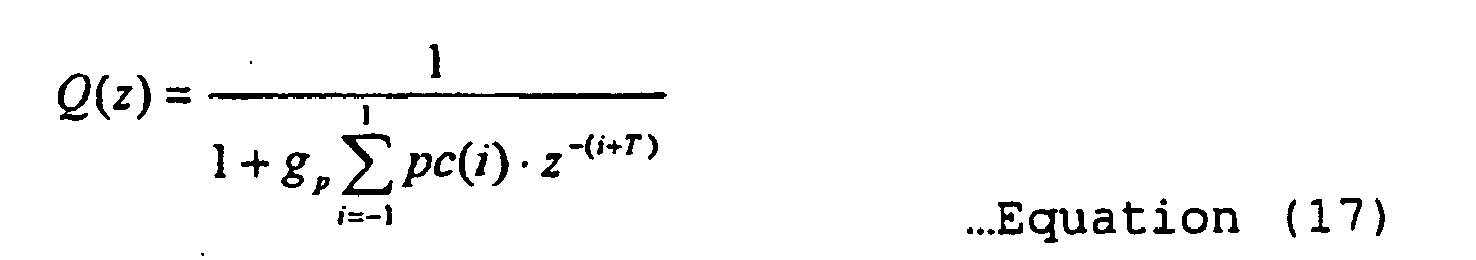
- The
synthesis filter 30 substitutes the obtained vocal source signal r' (n), as described above, into the equation (11) in stead of the r(n) to obtain an output voice s(n). - Note that the present embodiment uses a three-tap IIR filter for the pitch emphasis filter, but it is not limited as such and rather it may be possible to change a tap length or use other discretionary filters such as FIR filters.
- As described above, the third embodiment emphasizes a pitch cycle component contained by a vocal source signal by further comprising a pitch emphasis filter in addition to the configuration of the first embodiment, thereby making it possible to improve voice clarity further as compared thereto. That is, restoring a vocal source characteristic (i.e., residual differential signal) and a vocal tract characteristic by separating an input voice code and applying emphasis processes respectively suitable thereto, i.e., emphasizing the pitch cyclicality for the vocal source characteristic while emphasizing formants for the vocal tract characteristics makes it possible to further improve the output voice clarity.
-
Fig. 11 shows a hardware configuration of a mobile phone/PHS (i.e., Personal Handy-phone System) as one application of a speech decoder of the present embodiment. Note that a mobile phone, capable of performing discretionary processing by executing a program, et cetera, can be considered as a sort of computer. - The mobile phone/
PHS 70 shown byFig. 11 comprises anantenna 71, aradio transmission unit 72, an AD/DA converter 73, a DSP (Digital Signal Processor) 74, aCPU 75,memory 76, adisplay unit 77, aspeaker 78 and amicrophone 79. - The
DSP 74 executing a prescribed program stored in thememory 76 for a voice code code received by way of theantenna 71,radio transmission unit 72 and AD/DA converter 73 achieves the speech decoding processing described in reference toFigs. 1 through 10 to output an output voice. - Also described above, the application of the speech decoder according to embodiments of the present invention is in no way limited to the mobile phone, but may be VoIP (Voice over Internet Protocol) or a video conference system for example. That is, any kind of computer having the function of communicating by wired or wireless means by applying a voice coding method for compressing voice and capable of performing the speech decoding processing as described in reference to
Figs. 1 through 10 . -
Fig. 12 exemplifies an overview of the hardware configuration of such a computer. - The
computer 80 shown byFig. 12 comprises aCPU 81,memory 82, aninput apparatus 83, anoutput apparatus 84, anexternal storage apparatus 85, amedia drive apparatus 86, and anetwork connection apparatus 87, and abus 88 connecting the aforementioned components.Fig. 12 exemplifies a generalized configuration that may vary. - The
memory 82 is memory such as RAM for temporarily storing a program or data stored in the external storage apparatus 85 (or a portable storage medium 89) when executing the program or renewing the data. - The
CPU 81 accomplishes the above described various processes and functions (i.e., the processes shown byFigs. 4 and8 ; and the functions of the respective functional units shown byFigs. 1 through 3 ,7 and10 ) by executing the program loaded into thememory 82. - The
input apparatus 83 comprises a keyboard, a mouse, a touch panel, a microphone, for example. - The
output apparatus 84 comprises a display and a speaker, for example. - The
external storage apparatus 85, comprises a magnetic disk, an optical disk and magneto optical disk apparatuses, stores the program and data, et cetera, for the speech decoder to accomplish the above described various functions. - The media drive
apparatus 86 reads out the program and data stored in theportable storage medium 89. Theportable storage medium 89 comprises an FD (Flexible Disk), a CD-ROM, and other media such as a DVD, a magneto optical disk, for example. - The
network connection apparatus 87 is configured to enable the program and data exchanges with an external information processing apparatus by connecting with a network. -
Fig. 13 exemplifies a storage medium storing the above described program and downloading of the program. - As shown by
Fig. 13 , a configuration may be such that the program and data for accomplishing the functions of embodiments of the present invention are read from theportable storage medium 89 to thecomputer 80, stored in the memory and executed, or alternatively the aforementioned program and data stored in astorage unit 2 comprised by anexternal server 1 are downloaded through a network 3 (e.g., the Internet) by way of thenetwork connection apparatus 87. - Embodiments of the present invention are not limited either by an apparatus or method, but it may be configured as a storage medium (e.g., portable storage media 89) per se storing the above described program and data, or as the above described program per se.
- Lastly, let us describe the prior patent application (i.e., international application number
JP02/11332 -
Fig. 14 shows the basic configuration ofspeech emphasis apparatus 90 proposed by the prior patent application. - The
speech emphasis apparatus 90 shown byFig. 14 is characterized in such a way that a signal analysis/separation unit 91 first analyzes an input voice, x, and separates it into a vocal source signal, r, and a vocal tract characteristic sp1; a vocal tractcharacteristic modification unit 92 modifies the vocal tract characteristic sp1 (e.g., formant emphasis) and outputs the modified (i.e., emphasized) vocal tract characteristic sp2; and lastly asignal synthesis unit 93 re-synthesizes the vocal source signal, r, with the above described modified (i.e., emphasized) vocal tract characteristic sp2, thereby outputting a formant emphasized voice. - As described above, the prior patent application separates an input voice into a vocal source signal, r, and a vocal tract characteristic sp1, followed by emphasizing the vocal tract characteristic, thereby avoiding the distortion of the vocal source signal that has been a problem associated with the method noted by the
patent document 1. Therefore it is possible to apply formant emphasis without causing an increased sense of noisiness or decreased voice clarity. - Incidentally,
Fig. 15 exemplifies a configuration in the case of applying the speech emphasis apparatus presented by the prior patent application to a mobile phone, et cetera, equipped with a CELP decoder. - The
speech emphasis apparatus 90 noted by the prior patent application, receiving a voice, x, as described above, comprises a decoding processing apparatus 100 in the front stage thereof for decoding a voice code code transmitted from the outside in the decoding processing apparatus 100 to input the decoded voice, s, to thespeech emphasis apparatus 90 as shown byFig. 15 . - In the decoding processing apparatus 100 for instance, a code separation/
decoding unit 101 generates a vocal source signal r1 and a vocal tract characteristic sp1 from the voice code code and asignal synthesis unit 102 synthesize them to generates and outputs a decoded voice, s. In the process, the decoded voice, s, has its information compressed and therefore the amount of information is reduced as compared to the voice prior to the coding and accordingly is of poor quality. - Because of the above, having received the decoded voice, s, of a degraded quality, the
speech emphasis apparatus 90 re-analyzes the voice of a degraded quality to separate a vocal source signal and a vocal tract characteristic. This then causes a degraded separation accuracy, sometimes resulting in a vocal source signal component remaining in a vocal tract characteristic sp1' which is separated from the decoded voice, s, or a vocal tract characteristic which remains in a vocal source signal r1'. Therefore, there is a possibility of emphasizing a vocal source signal component remaining in the vocal tract characteristic, or failing to emphasize a vocal tract characteristic remaining in the vocal source signal, when the vocal tract characteristic is emphasized. This in turn has made it possible to degrade the quality of output voice s' having been re-synthesized from the vocal source signal and the formant emphasized vocal tract characteristic. - Contrary to the above described, the speech decoder according to embodiments of the present invention uses a vocal tract characteristic decoded from a voice code, eliminating the case of quality degradation due to a re-analysis of a degraded voice. Furthermore, an elimination of re-analysis makes it possible to reduce the processing load.
- As described in detail above, the speech decoder, decoding method and the program, in a communication apparatus such as mobile phone using a voice coding method in an analysis-synthesis system, having received a voice code which has been processed with a voice coding prior to the transmission, restores a vocal tract characteristic and a vocal source signal from the voice code, applies formant emphasis to the restored vocal tract characteristic to synthesize it with the vocal source signal when generating and outputting a voice based on the voice code. This suppresses distortion of the spectrum occurring when a vocal tract characteristic and a vocal source signal are simultaneously emphasized that has been a problem with the conventional technique, thereby making it possible to improve the clarity. That is, it is possible to decode a voice without causing a second effect such as a degradation of voice quality or an increased sense of noisiness, enabling ease of hearing with improved voice clarity.
Claims (13)
- A speech decoder, in the speech decoder comprised by a communication apparatus using a voice coding method in an analysis-synthesis system, comprising:a code separation/decoding unit for restoring a vocal tract characteristic and a vocal source signal by separating a received voice code;a vocal tract characteristic modification unit for modifying the vocal tract characteristic; anda signal synthesis unit for outputting a voice signal by synthesizing the modified vocal tract characteristic modified by the vocal tract characteristic modification unit and the vocal source signal obtained from the voice code;wherein,said vocal tract characteristic modification unit comprises a formant estimation unit for estimating a plurality of formants in said vocal tract characteristic, an amplification ratio calculation unit for calculating a plurality of amplification ratios for the vocal tract characteristic with each amplification ratio based on an estimated formant, and an emphasis unit for emphasizing the vocal tract characteristic based on said calculated amplification ratios; andsaid formant estimation unit is arranged to estimate a formant frequency and amplitude for each of said formants,said amplification ratio calculation unit is arranged to calculate an amplification reference power from said vocal tract characteristic and determines the amplification ratio of each formant so as to match each formant amplitude with the same amplification reference power, andsaid emphasis unit is arranged to emphasize the vocal tract characteristic by using the amplification ratio of each formant.
- The speech decoder according to Claim 1, wherein said amplification ratio calculation unit calculates the amplification ratio of each formant by dividing said same amplification reference power by the formant amplitude.
- A speech decoder according to any preceding claim, wherein:said amplification ratio calculation unit further obtains an amplification ratio of a frequency band between the formants from an interpolation curve, andsaid emphasis unit emphasizes said vocal tract characteristic by also using the amplification ratio obtained from the interpolation curve.
- A speech decoder according to any preceding claim, wherein:said formant estimation unit is arranged to estimate the frequencies and amplitudes of a plurality of anti-formants;said amplification ratio calculation unit is arranged to calculate a plurality of amplification ratios for the vocal tract characteristic with each amplification ratio based on an estimated anti-formant and calculate a second amplification reference power from the vocal tract characteristic and determines the amplification ratio of each anti-formant so as to match each anti-formant amplitude with the same second amplification reference power; andsaid emphasis unit is arranged to emphasize and attenuate the vocal tract characteristic by using an amplification ratio of a formant and amplification ratio of an anti-formant, respectively, both of which are determined by said amplification ratio calculation unit.
- A speech decoder according to any preceding claim, further comprising:a pitch emphasis unit for applying pitch emphasis to said vocal source signal; andsaid signal synthesis unit is arranged to output the voice signal by synthesizing the modified vocal tract characteristic modified by the vocal tract characteristic modification unit and the pitch emphasized vocal source signal.
- The speech decoder according to Claim 5, further comprising:a pitch emphasis filter configuration unit for calculating a auto-correlation function of a vocal source signal in the proximity of a pitch lag based thereon obtained according to an ACB code as a part of said voice code to calculate a pitch predictor coefficient from the auto-correlation function, wherein:said pitch emphasis unit generates said emphasized vocal source signal by filtering said vocal source signal with a pitch emphasis filter configured by the pitch predictor coefficient.
- The speech decoder according to any preceding claim, wherein said voice coding method is a voice coding method in the CELP system.
- A speech decoding method, in the speech decoding method for a communication apparatus using a voice coding method in an analysis-synthesis system, comprising the steps of:restoring a vocal tract characteristic and a vocal source signal by separating a received voice code;modifying the vocal tract characteristic; andoutputting a voice signal by synthesizing the modified vocal tract characteristic and the vocal source signal obtained from the voice code;wherein,said step of modifying the vocal tract characteristic comprises estimating a plurality of formants in said vocal tract characteristic, calculating a plurality of amplification ratios for the vocal tract characteristic with each amplification ratio based on an estimated formant, and emphasizing the vocal tract characteristic based on said calculated amplification ratios; andsaid step of estimating a plurality of formants estimates a formant frequency and amplitude for each of said formants,said step of calculating a plurality of amplification ratios calculates an amplification reference power from said vocal tract characteristic and determines the amplification ratio of each formant so as to match each formant amplitude with the same amplification reference power, andsaid step of emphasizing the vocal tract characteristic emphasizes the vocal tract characteristic by using the amplification ratio of each formant.
- A speech decoding method according to Claim 8, further comprising the steps of:estimating the frequencies and amplitudes of a plurality of anti-formants;calculating a plurality of amplification ratios for the vocal tract characteristic with each amplification ratio based on an estimated anti-formant and calculating a second amplification reference power from the vocal tract characteristic and determining the amplification ratio of each anti-formant so as to match each anti-formant amplitude with the same second amplification reference power; andemphasizing and attenuating the vocal tract characteristic by using an amplification ratio of a formant and amplification ratio of an anti-formant, respectively, both of which are determined by an amplification ratio calculation unit.
- A program for a computer to accomplish the functions of separating a received voice code to restore a vocal tract characteristic and a vocal source signal when receiving the voice code transmitted after being coded by a voice coding method in an analysis-synthesis system;modifying the vocal tract characteristic; andoutputting a voice signal by synthesizing the modified vocal tract characteristic and the vocal source signal obtained from the voice code;wherein,said step of modifying the vocal tract characteristic comprises estimating a plurality of formants in said vocal tract characteristic, calculating a plurality of amplification ratios for the vocal tract characteristic with each amplification ratio based on an estimated formant, and emphasizing the vocal tract characteristic based on said calculated amplification ratios; andsaid step of estimating a plurality of formants estimates a formant frequency and amplitude for each of said formants,said step of calculating a plurality of amplification ratios calculates an amplification reference power from said vocal tract characteristic and determines the amplification ratio of each formant so as to match each formant amplitude with the same amplification reference power, andsaid step of emphasizing the vocal tract characteristic emphasizes the vocal tract characteristic by using the amplification ratio of each formant.
- The program for a computer according to Claim 10, further accomplishing the functions of:estimating the frequencies and amplitudes of a plurality of anti-formants;calculating a plurality of amplification ratios for the vocal tract characteristic with each amplification ratio based on an estimated anti-formant and calculating a second amplification reference power from the vocal tract characteristic and determining the amplification ratio of each anti-formant so as to match each anti-formant amplitude with the same second amplification reference power; andemphasizing and attenuating the vocal tract characteristic by using an amplification ratio of a formant and amplification ratio of an anti-formant, respectively, both of which are determined by an amplification ratio calculation unit.
- A computer readable storage medium storing a program for a computer executing the functions of:separating a received voice code to restore a vocal tract characteristic and a vocal source signal when receiving the voice code transmitted after being coded by a voice coding method in an analysis-synthesis system;modifying the vocal tract characteristic; andoutputting a voice signal by synthesizing the modified vocal tract characteristic and the vocal source signal obtained from the voice code;wherein,said step of modifying the vocal tract characteristic comprises estimating a plurality of formants in said vocal tract characteristic, calculating a plurality of amplification ratios for the vocal tract characteristic with each amplification ratio based on an estimated formant, and emphasizing the vocal tract characteristic based on said calculated amplification ratios; andsaid step of estimating a plurality of formants estimates a formant frequency and amplitude for each of said formants,said step of calculating a plurality of amplification ratios calculates an amplification reference power from said vocal tract characteristic and determines the amplification ratio of each formant so as to match each formant amplitude with the same amplification reference power, andsaid step of emphasizing the vocal tract characteristic emphasizes the vocal tract characteristic by using the amplification ratio of each formant.
- The storage medium according to Claim 12, wherein the program for a computer further executes the functions of:estimating the frequencies and amplitudes of a plurality of anti-formants;calculating a plurality of amplification ratios for the vocal tract characteristic with each amplification ratio based on an estimated anti-formant and calculating a second amplification reference power from the vocal tract characteristic and determining the amplification ratio of each anti-formant so as to match each anti-formant amplitude with the same second amplification reference power; andemphasizing and attenuating the vocal tract characteristic by using an amplification ratio of a formant and amplification ratio of an anti-formant, respectively, both of which are determined by an amplification ratio calculation unit.
Applications Claiming Priority (1)
| Application Number | Priority Date | Filing Date | Title |
|---|---|---|---|
| PCT/JP2003/005582 WO2004097798A1 (en) | 2003-05-01 | 2003-05-01 | Speech decoder, speech decoding method, program, recording medium |
Publications (3)
| Publication Number | Publication Date |
|---|---|
| EP1619666A1 EP1619666A1 (en) | 2006-01-25 |
| EP1619666A4 EP1619666A4 (en) | 2007-08-01 |
| EP1619666B1 true EP1619666B1 (en) | 2009-12-23 |
Family
ID=33398154
Family Applications (1)
| Application Number | Title | Priority Date | Filing Date |
|---|---|---|---|
| EP03721013A Expired - Lifetime EP1619666B1 (en) | 2003-05-01 | 2003-05-01 | Speech decoder, speech decoding method, program, recording medium |
Country Status (5)
| Country | Link |
|---|---|
| US (1) | US7606702B2 (en) |
| EP (1) | EP1619666B1 (en) |
| JP (1) | JP4786183B2 (en) |
| DE (1) | DE60330715D1 (en) |
| WO (1) | WO2004097798A1 (en) |
Families Citing this family (10)
| Publication number | Priority date | Publication date | Assignee | Title |
|---|---|---|---|---|
| US8554548B2 (en) * | 2007-03-02 | 2013-10-08 | Panasonic Corporation | Speech decoding apparatus and speech decoding method including high band emphasis processing |
| JP2010191302A (en) * | 2009-02-20 | 2010-09-02 | Sharp Corp | Voice-outputting device |
| US9031834B2 (en) | 2009-09-04 | 2015-05-12 | Nuance Communications, Inc. | Speech enhancement techniques on the power spectrum |
| JP5648123B2 (en) * | 2011-04-20 | 2015-01-07 | パナソニック インテレクチュアル プロパティ コーポレーション オブアメリカPanasonic Intellectual Property Corporation of America | Speech acoustic coding apparatus, speech acoustic decoding apparatus, and methods thereof |
| MX346927B (en) * | 2013-01-29 | 2017-04-05 | Fraunhofer Ges Forschung | Low-frequency emphasis for lpc-based coding in frequency domain. |
| EP3848929B1 (en) * | 2013-03-04 | 2023-07-12 | VoiceAge EVS LLC | Device and method for reducing quantization noise in a time-domain decoder |
| EP2980799A1 (en) | 2014-07-28 | 2016-02-03 | Fraunhofer-Gesellschaft zur Förderung der angewandten Forschung e.V. | Apparatus and method for processing an audio signal using a harmonic post-filter |
| CN107851433B (en) * | 2015-12-10 | 2021-06-29 | 华侃如 | Speech analysis and synthesis method based on harmonic model and sound source-channel feature decomposition |
| JP2018159759A (en) | 2017-03-22 | 2018-10-11 | 株式会社東芝 | Voice processor, voice processing method and program |
| JP6646001B2 (en) * | 2017-03-22 | 2020-02-14 | 株式会社東芝 | Audio processing device, audio processing method and program |
Family Cites Families (24)
| Publication number | Priority date | Publication date | Assignee | Title |
|---|---|---|---|---|
| JPH0738118B2 (en) | 1987-02-04 | 1995-04-26 | 日本電気株式会社 | Multi-pulse encoder |
| JPH05323997A (en) * | 1991-04-25 | 1993-12-07 | Matsushita Electric Ind Co Ltd | Speech coder, speech decoder, speech coder |
| WO1993018505A1 (en) * | 1992-03-02 | 1993-09-16 | The Walt Disney Company | Voice transformation system |
| JPH0738118A (en) | 1992-12-22 | 1995-02-07 | Korea Electron Telecommun | Method of manufacturing thin film transistor |
| JP3510643B2 (en) * | 1993-01-07 | 2004-03-29 | 株式会社東芝 | Pitch period processing method for audio signal |
| JPH06202695A (en) | 1993-01-07 | 1994-07-22 | Sony Corp | Speech signal processor |
| JP3360423B2 (en) * | 1994-06-21 | 2002-12-24 | 三菱電機株式会社 | Voice enhancement device |
| JP3235703B2 (en) * | 1995-03-10 | 2001-12-04 | 日本電信電話株式会社 | Method for determining filter coefficient of digital filter |
| JPH08272394A (en) | 1995-03-30 | 1996-10-18 | Olympus Optical Co Ltd | Voice encoding device |
| JP2993396B2 (en) * | 1995-05-12 | 1999-12-20 | 三菱電機株式会社 | Voice processing filter and voice synthesizer |
| EP0763818B1 (en) | 1995-09-14 | 2003-05-14 | Kabushiki Kaisha Toshiba | Formant emphasis method and formant emphasis filter device |
| JP3483998B2 (en) * | 1995-09-14 | 2004-01-06 | 株式会社東芝 | Pitch enhancement method and apparatus |
| JP3319556B2 (en) * | 1995-09-14 | 2002-09-03 | 株式会社東芝 | Formant enhancement method |
| EP0788091A3 (en) * | 1996-01-31 | 1999-02-24 | Kabushiki Kaisha Toshiba | Speech encoding and decoding method and apparatus therefor |
| JP3357795B2 (en) * | 1996-08-16 | 2002-12-16 | 株式会社東芝 | Voice coding method and apparatus |
| JPH10105200A (en) * | 1996-09-26 | 1998-04-24 | Toshiba Corp | Audio encoding / decoding method |
| US6003000A (en) * | 1997-04-29 | 1999-12-14 | Meta-C Corporation | Method and system for speech processing with greatly reduced harmonic and intermodulation distortion |
| US6098036A (en) * | 1998-07-13 | 2000-08-01 | Lockheed Martin Corp. | Speech coding system and method including spectral formant enhancer |
| JP2000099094A (en) * | 1998-09-25 | 2000-04-07 | Matsushita Electric Ind Co Ltd | Time series signal processing device |
| JP2001117573A (en) * | 1999-10-20 | 2001-04-27 | Toshiba Corp | Audio spectrum enhancement method / apparatus and audio decoding apparatus |
| JP3612260B2 (en) * | 2000-02-29 | 2005-01-19 | 株式会社東芝 | Speech encoding method and apparatus, and speech decoding method and apparatus |
| US6665638B1 (en) * | 2000-04-17 | 2003-12-16 | At&T Corp. | Adaptive short-term post-filters for speech coders |
| JP4413480B2 (en) | 2002-08-29 | 2010-02-10 | 富士通株式会社 | Voice processing apparatus and mobile communication terminal apparatus |
| JP4219898B2 (en) * | 2002-10-31 | 2009-02-04 | 富士通株式会社 | Speech enhancement device |
-
2003
- 2003-05-01 JP JP2004571323A patent/JP4786183B2/en not_active Expired - Fee Related
- 2003-05-01 DE DE60330715T patent/DE60330715D1/en not_active Expired - Lifetime
- 2003-05-01 EP EP03721013A patent/EP1619666B1/en not_active Expired - Lifetime
- 2003-05-01 WO PCT/JP2003/005582 patent/WO2004097798A1/en not_active Ceased
-
2005
- 2005-04-27 US US11/115,478 patent/US7606702B2/en not_active Expired - Fee Related
Also Published As
| Publication number | Publication date |
|---|---|
| WO2004097798A1 (en) | 2004-11-11 |
| US7606702B2 (en) | 2009-10-20 |
| DE60330715D1 (en) | 2010-02-04 |
| EP1619666A4 (en) | 2007-08-01 |
| US20050187762A1 (en) | 2005-08-25 |
| JPWO2004097798A1 (en) | 2006-07-13 |
| JP4786183B2 (en) | 2011-10-05 |
| EP1619666A1 (en) | 2006-01-25 |
Similar Documents
| Publication | Publication Date | Title |
|---|---|---|
| EP0673013B1 (en) | Signal encoding and decoding system | |
| RU2262748C2 (en) | Multi-mode encoding device | |
| JP4308345B2 (en) | Multi-mode speech encoding apparatus and decoding apparatus | |
| US6735567B2 (en) | Encoding and decoding speech signals variably based on signal classification | |
| US8209188B2 (en) | Scalable coding/decoding apparatus and method based on quantization precision in bands | |
| US6574593B1 (en) | Codebook tables for encoding and decoding | |
| RU2389085C2 (en) | Method and device for introducing low-frequency emphasis when compressing sound based on acelp/tcx | |
| JP3653826B2 (en) | Speech decoding method and apparatus | |
| EP1141946B1 (en) | Coded enhancement feature for improved performance in coding communication signals | |
| JP4302978B2 (en) | Pseudo high-bandwidth signal estimation system for speech codec | |
| JP4040126B2 (en) | Speech decoding method and apparatus | |
| US6052659A (en) | Nonlinear filter for noise suppression in linear prediction speech processing devices | |
| JP2004102186A (en) | Acoustic encoding apparatus and acoustic encoding method | |
| EP1619666B1 (en) | Speech decoder, speech decoding method, program, recording medium | |
| JP2000122695A (en) | Back-end filter | |
| KR20070007851A (en) | Hierarchical Coding Device and Hierarchical Coding Method | |
| EP3281197B1 (en) | Audio encoder and method for encoding an audio signal | |
| JP4527175B2 (en) | Spectral parameter smoothing apparatus and spectral parameter smoothing method | |
| EP1564723A1 (en) | Transcoder and coder conversion method | |
| JP3785363B2 (en) | Audio signal encoding apparatus, audio signal decoding apparatus, and audio signal encoding method | |
| JP3560964B2 (en) | Broadband audio restoration apparatus, wideband audio restoration method, audio transmission system, and audio transmission method | |
| JP3773509B2 (en) | Broadband speech restoration apparatus and broadband speech restoration method | |
| JPH09146598A (en) | Noise suppression method in speech coding | |
| JPH09179588A (en) | Audio coding method |
Legal Events
| Date | Code | Title | Description |
|---|---|---|---|
| PUAI | Public reference made under article 153(3) epc to a published international application that has entered the european phase |
Free format text: ORIGINAL CODE: 0009012 |
|
| 17P | Request for examination filed |
Effective date: 20050519 |
|
| AK | Designated contracting states |
Kind code of ref document: A1 Designated state(s): AT BE BG CH CY CZ DE DK EE ES FI FR GB GR HU IE IT LI LU MC NL PT RO SE SI SK TR |
|
| RBV | Designated contracting states (corrected) |
Designated state(s): DE FR GB |
|
| A4 | Supplementary search report drawn up and despatched |
Effective date: 20070703 |
|
| RIC1 | Information provided on ipc code assigned before grant |
Ipc: G10L 19/08 20060101AFI20041117BHEP Ipc: G10L 21/02 20060101ALI20070627BHEP Ipc: G10L 19/12 20060101ALI20070627BHEP |
|
| 17Q | First examination report despatched |
Effective date: 20080703 |
|
| GRAP | Despatch of communication of intention to grant a patent |
Free format text: ORIGINAL CODE: EPIDOSNIGR1 |
|
| GRAS | Grant fee paid |
Free format text: ORIGINAL CODE: EPIDOSNIGR3 |
|
| GRAA | (expected) grant |
Free format text: ORIGINAL CODE: 0009210 |
|
| AK | Designated contracting states |
Kind code of ref document: B1 Designated state(s): DE FR GB |
|
| REG | Reference to a national code |
Ref country code: GB Ref legal event code: FG4D |
|
| REF | Corresponds to: |
Ref document number: 60330715 Country of ref document: DE Date of ref document: 20100204 Kind code of ref document: P |
|
| PLBE | No opposition filed within time limit |
Free format text: ORIGINAL CODE: 0009261 |
|
| STAA | Information on the status of an ep patent application or granted ep patent |
Free format text: STATUS: NO OPPOSITION FILED WITHIN TIME LIMIT |
|
| 26N | No opposition filed |
Effective date: 20100924 |
|
| REG | Reference to a national code |
Ref country code: FR Ref legal event code: PLFP Year of fee payment: 14 |
|
| REG | Reference to a national code |
Ref country code: FR Ref legal event code: PLFP Year of fee payment: 15 |
|
| REG | Reference to a national code |
Ref country code: FR Ref legal event code: PLFP Year of fee payment: 16 |
|
| PGFP | Annual fee paid to national office [announced via postgrant information from national office to epo] |
Ref country code: DE Payment date: 20190416 Year of fee payment: 17 |
|
| PGFP | Annual fee paid to national office [announced via postgrant information from national office to epo] |
Ref country code: FR Payment date: 20190410 Year of fee payment: 17 |
|
| PGFP | Annual fee paid to national office [announced via postgrant information from national office to epo] |
Ref country code: GB Payment date: 20190501 Year of fee payment: 17 |
|
| REG | Reference to a national code |
Ref country code: DE Ref legal event code: R119 Ref document number: 60330715 Country of ref document: DE |
|
| GBPC | Gb: european patent ceased through non-payment of renewal fee |
Effective date: 20200501 |
|
| PG25 | Lapsed in a contracting state [announced via postgrant information from national office to epo] |
Ref country code: GB Free format text: LAPSE BECAUSE OF NON-PAYMENT OF DUE FEES Effective date: 20200501 Ref country code: FR Free format text: LAPSE BECAUSE OF NON-PAYMENT OF DUE FEES Effective date: 20200531 |
|
| PG25 | Lapsed in a contracting state [announced via postgrant information from national office to epo] |
Ref country code: DE Free format text: LAPSE BECAUSE OF NON-PAYMENT OF DUE FEES Effective date: 20201201 |