EP1529694A1 - Power supply for vehicle - Google Patents
Power supply for vehicle Download PDFInfo
- Publication number
- EP1529694A1 EP1529694A1 EP04747155A EP04747155A EP1529694A1 EP 1529694 A1 EP1529694 A1 EP 1529694A1 EP 04747155 A EP04747155 A EP 04747155A EP 04747155 A EP04747155 A EP 04747155A EP 1529694 A1 EP1529694 A1 EP 1529694A1
- Authority
- EP
- European Patent Office
- Prior art keywords
- capacitor unit
- power supply
- internal resistance
- resistance value
- unit
- Prior art date
- Legal status (The legal status is an assumption and is not a legal conclusion. Google has not performed a legal analysis and makes no representation as to the accuracy of the status listed.)
- Granted
Links
Images




Classifications
-
- H—ELECTRICITY
- H02—GENERATION; CONVERSION OR DISTRIBUTION OF ELECTRIC POWER
- H02J—ELECTRIC POWER NETWORKS; CIRCUIT ARRANGEMENTS OR SYSTEMS FOR SUPPLYING OR DISTRIBUTING ELECTRIC POWER; SYSTEMS FOR STORING ELECTRIC ENERGY
- H02J7/00—Circuit arrangements for charging or discharging batteries or for supplying loads from batteries
- H02J7/14—Circuit arrangements for charging or discharging batteries or for supplying loads from batteries for charging batteries from dynamo-electric generators driven at varying speed, e.g. on vehicle
- H02J7/1423—Circuit arrangements for charging or discharging batteries or for supplying loads from batteries for charging batteries from dynamo-electric generators driven at varying speed, e.g. on vehicle with multiple batteries
-
- B—PERFORMING OPERATIONS; TRANSPORTING
- B60—VEHICLES IN GENERAL
- B60R—VEHICLES, VEHICLE FITTINGS, OR VEHICLE PARTS, NOT OTHERWISE PROVIDED FOR
- B60R16/00—Electric or fluid circuits specially adapted for vehicles and not otherwise provided for; Arrangement of elements of electric or fluid circuits specially adapted for vehicles and not otherwise provided for
- B60R16/02—Electric or fluid circuits specially adapted for vehicles and not otherwise provided for; Arrangement of elements of electric or fluid circuits specially adapted for vehicles and not otherwise provided for electric constitutive elements
- B60R16/023—Electric or fluid circuits specially adapted for vehicles and not otherwise provided for; Arrangement of elements of electric or fluid circuits specially adapted for vehicles and not otherwise provided for electric constitutive elements for transmission of signals between vehicle parts or subsystems
-
- B—PERFORMING OPERATIONS; TRANSPORTING
- B60—VEHICLES IN GENERAL
- B60T—VEHICLE BRAKE CONTROL SYSTEMS OR PARTS THEREOF; BRAKE CONTROL SYSTEMS OR PARTS THEREOF, IN GENERAL; ARRANGEMENT OF BRAKING ELEMENTS ON VEHICLES IN GENERAL; PORTABLE DEVICES FOR PREVENTING UNWANTED MOVEMENT OF VEHICLES; VEHICLE MODIFICATIONS TO FACILITATE COOLING OF BRAKES
- B60T13/00—Transmitting braking action from initiating means to ultimate brake actuator with power assistance or drive; Brake systems incorporating such transmitting means, e.g. air-pressure brake systems
- B60T13/74—Transmitting braking action from initiating means to ultimate brake actuator with power assistance or drive; Brake systems incorporating such transmitting means, e.g. air-pressure brake systems with electrical assistance or drive
-
- H—ELECTRICITY
- H02—GENERATION; CONVERSION OR DISTRIBUTION OF ELECTRIC POWER
- H02J—ELECTRIC POWER NETWORKS; CIRCUIT ARRANGEMENTS OR SYSTEMS FOR SUPPLYING OR DISTRIBUTING ELECTRIC POWER; SYSTEMS FOR STORING ELECTRIC ENERGY
- H02J7/00—Circuit arrangements for charging or discharging batteries or for supplying loads from batteries
- H02J7/34—Parallel operation in networks using both storage and other DC sources, e.g. providing buffering
- H02J7/345—Parallel operation in networks using both storage and other DC sources, e.g. providing buffering using capacitors as storage or buffering devices
-
- H—ELECTRICITY
- H02—GENERATION; CONVERSION OR DISTRIBUTION OF ELECTRIC POWER
- H02J—ELECTRIC POWER NETWORKS; CIRCUIT ARRANGEMENTS OR SYSTEMS FOR SUPPLYING OR DISTRIBUTING ELECTRIC POWER; SYSTEMS FOR STORING ELECTRIC ENERGY
- H02J7/00—Circuit arrangements for charging or discharging batteries or for supplying loads from batteries
- H02J7/60—Circuit arrangements for charging or discharging batteries or for supplying loads from batteries including safety or protection arrangements
-
- H—ELECTRICITY
- H02—GENERATION; CONVERSION OR DISTRIBUTION OF ELECTRIC POWER
- H02J—ELECTRIC POWER NETWORKS; CIRCUIT ARRANGEMENTS OR SYSTEMS FOR SUPPLYING OR DISTRIBUTING ELECTRIC POWER; SYSTEMS FOR STORING ELECTRIC ENERGY
- H02J7/00—Circuit arrangements for charging or discharging batteries or for supplying loads from batteries
- H02J7/80—Circuit arrangements for charging or discharging batteries or for supplying loads from batteries including monitoring or indicating arrangements
- H02J7/84—Control of state of health [SOH]
-
- B—PERFORMING OPERATIONS; TRANSPORTING
- B60—VEHICLES IN GENERAL
- B60R—VEHICLES, VEHICLE FITTINGS, OR VEHICLE PARTS, NOT OTHERWISE PROVIDED FOR
- B60R16/00—Electric or fluid circuits specially adapted for vehicles and not otherwise provided for; Arrangement of elements of electric or fluid circuits specially adapted for vehicles and not otherwise provided for
- B60R16/02—Electric or fluid circuits specially adapted for vehicles and not otherwise provided for; Arrangement of elements of electric or fluid circuits specially adapted for vehicles and not otherwise provided for electric constitutive elements
- B60R16/03—Electric or fluid circuits specially adapted for vehicles and not otherwise provided for; Arrangement of elements of electric or fluid circuits specially adapted for vehicles and not otherwise provided for electric constitutive elements for supply of electrical power to vehicle subsystems or for
-
- H—ELECTRICITY
- H02—GENERATION; CONVERSION OR DISTRIBUTION OF ELECTRIC POWER
- H02J—ELECTRIC POWER NETWORKS; CIRCUIT ARRANGEMENTS OR SYSTEMS FOR SUPPLYING OR DISTRIBUTING ELECTRIC POWER; SYSTEMS FOR STORING ELECTRIC ENERGY
- H02J2105/00—Networks for supplying or distributing electric power characterised by their spatial reach or by the load
- H02J2105/30—Networks for supplying or distributing electric power characterised by their spatial reach or by the load the load networks being external to vehicles, i.e. exchanging power with vehicles
- H02J2105/33—Networks for supplying or distributing electric power characterised by their spatial reach or by the load the load networks being external to vehicles, i.e. exchanging power with vehicles exchanging power with road vehicles
-
- H—ELECTRICITY
- H02—GENERATION; CONVERSION OR DISTRIBUTION OF ELECTRIC POWER
- H02J—ELECTRIC POWER NETWORKS; CIRCUIT ARRANGEMENTS OR SYSTEMS FOR SUPPLYING OR DISTRIBUTING ELECTRIC POWER; SYSTEMS FOR STORING ELECTRIC ENERGY
- H02J2105/00—Networks for supplying or distributing electric power characterised by their spatial reach or by the load
- H02J2105/30—Networks for supplying or distributing electric power characterised by their spatial reach or by the load the load networks being external to vehicles, i.e. exchanging power with vehicles
- H02J2105/33—Networks for supplying or distributing electric power characterised by their spatial reach or by the load the load networks being external to vehicles, i.e. exchanging power with vehicles exchanging power with road vehicles
- H02J2105/37—Networks for supplying or distributing electric power characterised by their spatial reach or by the load the load networks being external to vehicles, i.e. exchanging power with vehicles exchanging power with road vehicles exchanging power with electric vehicles [EV] or with hybrid electric vehicles [HEV]
-
- Y—GENERAL TAGGING OF NEW TECHNOLOGICAL DEVELOPMENTS; GENERAL TAGGING OF CROSS-SECTIONAL TECHNOLOGIES SPANNING OVER SEVERAL SECTIONS OF THE IPC; TECHNICAL SUBJECTS COVERED BY FORMER USPC CROSS-REFERENCE ART COLLECTIONS [XRACs] AND DIGESTS
- Y02—TECHNOLOGIES OR APPLICATIONS FOR MITIGATION OR ADAPTATION AGAINST CLIMATE CHANGE
- Y02T—CLIMATE CHANGE MITIGATION TECHNOLOGIES RELATED TO TRANSPORTATION
- Y02T10/00—Road transport of goods or passengers
- Y02T10/60—Other road transportation technologies with climate change mitigation effect
- Y02T10/70—Energy storage systems for electromobility, e.g. batteries
Definitions
- the present invention relates to a power supply apparatus for a vehicle mounted in a vehicle such as a hybrid car, an electric vehicle, and the like.
- a power supply apparatus for a vehicle for braking a vehicle electrically is a vehicle mounted in a vehicle such as a hybrid car, an electric vehicle, and the like.
- a battery is used as its power supply.
- the vehicle cannot be controlled with only this battery. Therefore, some configurations are equipped with an auxiliary battery as an auxiliary power supply in addition to the battery for the case of emergency.
- Japanese Patent Unexamined Publication No. H05-116571 is known.
- a power supply apparatus for a vehicle of the present invention has a following configuration.
- an electronic controller In order to control brakes, an electronic controller outputs information for controlling braking of a vehicle based on at least one of information provided from a brake pedal and information provided in response to a moving state of the vehicle.
- a battery supplies electric power to the brakes via the electronic controller.
- An auxiliary power supply includes a power supply backup unit having a capacitor unit formed of a plurality of capacitors and a detection unit for detecting an abnormality in the capacitor unit, and supplies electric power to the brakes via the electronic controller when the battery is in an abnormal state.
- the detection unit measures an internal resistance value of the capacitor unit, and measures an internal capacitance value of the capacitor unit from the rate of change of voltage per unit time of the capacitor unit.
- the detection unit judges whether or not the capacitor unit is in a normal state based on the measured internal resistance value and internal capacitance value.
- the capacitor unit is used as the auxiliary power supply, the lifetime as the auxiliary power supply is significantly extended, so that it can be extended to substantially the same level as the lifetime of the vehicle. As a result, a maintenance-free power supply backup unit can be realized. Furthermore, in charging or discharging, the internal resistance value is calculated from the voltage of the capacitor unit, and the internal capacitance value is calculated from the rate of change of voltage. Thereby, it is possible to measure the internal resistance value and the internal capacitance value of the capacitor unit more precisely. Thus, it is possible to judge whether or not the capacitor unit is in a normal state.
- FIG. 1 shows a configuration of a power supply apparatus for a vehicle in an embodiment of the present invention.
- 12V battery 1 supplies electric power into a vehicle.
- power supply backup unit 2 is provided.
- electronic controller 3 outputting information for controlling braking of the vehicle is provided. From both battery 1 and power supply backup unit 2, electric power is supplied to electronic controller 3.
- brake pedal 4 for transmitting information for controlling braking of the vehicle to electronic controller 3 is provided.
- Electronic controller 3 controls brakes 5 based on the information from brake pedal 4. With brakes 5, wheels 6 are braked.
- FIG. 2 is a circuit diagram showing a power supply apparatus for a vehicle in an embodiment of the present invention.
- battery 1 is connected to IG (ignition generator) terminal 9 provided on power supply backup unit 2 via ignition switch 8 for starting and terminating an operation of a vehicle, and also connected to +BC terminal 10 provided on power supply backup unit 2.
- +BC terminal 10 is a terminal for supplying electric power to power supply backup unit 2.
- Ignition switch 8 is provided for starting or terminating an operation of a vehicle.
- battery 1 is connected to power supply terminal 20 for supplying electric power to electronic controller 3.
- Power supply backup unit 2 and electronic controller 3 are connected to each other via communication input terminal 11, communication output terminal 12 and OUT terminal 13.
- communication input terminal 11 is a terminal for inputting signals from electronic controller 3 to power supply backup unit 2.
- Communication output terminal 12 is a terminal for outputting signals from power supply backup unit 2 to electronic controller 3.
- OUT terminal 13 is a terminal for outputting a voltage detected by a backup detector in power supply backup unit 2 or outputting electric charges stored in power supply backup unit 2 when battery 1 is in an abnormal state.
- Power supply backup unit 2 is an auxiliary power supply for supplying electric power to brakes 5 via electronic controller 3 when battery 1 is in an abnormal state.
- Power supply backup unit 2 includes capacitor unit 15.
- Capacitor unit 15 is formed of a plurality of capacitors, for example, configured by connecting a plurality of electric double layer capacitors capable of charging and discharging rapidly. Furthermore, power supply backup unit 2 includes charging circuit 16 for charging capacitor unit 15 and discharging circuit 17 for discharging capacitor unit 15. These are controlled based on an instruction from microprocessor 14. Charging circuit 16 includes a constant-current controller (not shown) in order to keep voltage increase in capacitor unit 15 in charging nearly constant.
- Power supply backup unit 2 includes voltage detector 18, as a first detection unit, for detecting a voltage output from battery 1. Furthermore, FET switch 19 is connected to voltage detector 18. FET switch 19 enables discharging electronic controller 3 from capacitor unit 15 via OUT terminal 13 when voltage detector 18 detects an abnormality in voltage.
- power supply backup unit 2 includes detection unit 22, as a second detection unit, for detecting an abnormality in capacitor unit 15 based on the charging and discharging behavior.
- Detection unit 22 includes microprocessor 14, charging circuit 16 and discharging circuit 17.
- the voltage output from battery 1 via +BC terminal 10 is detected by a sensor provided in voltage detector 18 and output to OUT terminal 13.
- the voltage applied from battery 1 is a standard value (9.5 V) or more, it is confirmed that the voltage from battery 1 and the operation of power supply backup unit 2 are in a normal state. Then, electric power is continuously supplied from battery 1 to electronic controller 3.
- the vehicle can operate normally.
- electronic controller 3 inputs information from brake pedal 4 and, based on the input information, outputs information for controlling braking of the vehicle to brakes 5. Then, in accordance with the output information, brakes 5 are operated, making it possible to brake wheels 6 reliably. Consequently, it is possible to control a vehicle reliably.
- microprocessor 14 transmits a signal for instructing discharging electric charges stored in capacitor unit 15 to discharging circuit 17. Then, based on this signal, discharging circuit 17 discharges electric charges stored in capacitor unit 15.
- the following is an explanation of an operation of the power supply apparatus for a vehicle when the voltage of battery 1 is lowered or is in an abnormal state.
- voltage detector 18 is provided with a sensor for detecting an abnormality in battery 1. Thereby, when the voltage detected by this sensor is less than the standard value (9.5 V), voltage detector 18 detects that the voltage output from battery 1 is abnormal.
- FET switch 19 which is basically turned OFF when battery 1 is in a normal state, is turned ON. At this time, discharging from capacitor unit 15 to OUT terminal 13 is possible and supplying of electric power from battery 1 is stopped. Then, voltage detector 18 outputs a signal, in response to the stop of supplying of electric power from battery 1, to microprocessor 14. Microprocessor 14 instructs discharging circuit 17 to discharge electric charges stored in capacitor unit 15. In accordance with this instruction, electric charges stored in capacitor unit 15 are output to OUT terminal 13 via FET switch 19 and supplied to electronic controller 3.
- this information on abnormality is transmitted from microprocessor 14 to electronic controller 3 via communication output terminal 12 and is displayed inside the vehicle. For example, information that battery 1 is in an abnormal state is displayed. Thereby, a driver is instructed to stop a vehicle immediately. In this way, when an abnormality is detected, since electric charges stored in capacitor unit 15 are supplied to electronic controller 3 as an emergency power supply, a driver can operate brakes 5 from brake pedal 4 via electronic controller 3, so that the driver can stop the vehicle safely.
- microcomputer 14 transmits the abnormality in capacitor unit 15 to electronic controller 3 via communication output terminal 12. Thereby, as in the time when battery 1 is in an abnormal state, it is displayed that capacitor unit 15 is in an abnormal state. Thereby, a driver can request a garage to carry out inspection, exchange, etc. of capacitor unit 15.
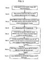
- FIG. 3 is a flow chart that shows judging deterioration and abnormality in capacitor unit 15.
- FIG. 4A shows a voltage of capacitor unit 15 in charging.
- FIG. 4B shows a voltage of capacitor unit 15 in discharging.
- FIG. 5A shows line 52 plotting standard values of the internal capacitance values, which were set in advance at respective temperatures, of capacitor unit 15.
- FIG. 5B shows line 54 plotting standard values of the internal resistance values, which were set in advance at respective temperatures, of capacitor unit 15.
- FIG. 6 shows limit values of the internal resistance values with respect to the internal capacitance values of capacitor unit 15, which were set in advance at respective temperatures.
- capacitor unit 15 starts to be charged, and temperatures are measured (Step (a) in FIG. 3).
- voltage detector 18 detects voltages charged in capacitor unit 15.
- charging is interrupted for a predetermined time during charging, i.e. from time T1 to T2 for, for example, about 80 ms.
- Voltage detector 18 detects a difference ⁇ V between the voltage when charging is interrupted and the dropped voltage.
- the internal resistance value of capacitor unit 15 is calculated. After charging is interrupted for 80 ms, charging is re-started. When voltage detector 18 detects that 12V is charged in capacitor unit 15, charging is completed.
- the internal capacitance value of capacitor unit 15 is calculated by measuring the rate of change of voltage per unit time in charging. At that time, even if capacitor unit 15 is charged with a constant current, the rate of change of voltage is not always constant due to the nonlinearity of the capacitor. That is to say, voltage does not change always linearly. Therefore, in order to calculate more precise rate of change of voltage, the rate of change of voltage, voltage and electric current are measured multiple times repeatedly at predetermined intervals, for example, every one second. From an average value of these measured values, the internal capacitance value and the internal resistance value are calculated (Step (b) in FIG. 3).
- capacitor unit 15 has an internal resistance value of 130 m ⁇ , an internal capacitance value of 10F and a temperature of 0°C.
- the internal capacitance value and the internal resistance value of capacitor unit 15 after charging can be estimated from the temperature of capacitor unit 15 when measurement is carried out.
- the estimating method is described hereinafter.
- the difference in the internal capacitance values is 4F and the difference in the internal resistance values is 70 m ⁇ .
- the measurement of temperatures of capacitor unit 15 is carried out at any time (Step (d) in FIG. 3).
- the corrected internal capacitance value and internal resistance value are compared with the limit resistance values with respect to the internal capacitance values of capacitor unit 15 set at respective temperatures shown in FIG. 6. Thus, it is judged whether or not capacitor unit 15 is deteriorated, i.e., whether or not capacitor unit 15 is in a normal state (Step (f) in FIG. 3).
- step (d) when it is judged that capacitor unit 15 is in a normal state, the step returns to step (d).
- the internal capacitance values and the internal resistance values when the temperature of capacitor unit 15 is changed from 0°C to 15°C and to 30°C are shown in FIG. 5A and FIG. 5B, respectively.
- the limit value is 230 m ⁇ as shown by reference numeral 62;
- capacitor unit 15 is in a normal state at 0°C and 15°C and in an abnormal state at 30°C.
- Step (h) in FIG. 3 it is displayed inside a vehicle that capacitor unit 15 is in an abnormal state due to deterioration, and thus the abnormality is notified to a driver.
- step (d) in FIG. 3 If it is judged that capacitor unit 15 is in a normal state at the time of re-measurement, the step returns to step (d) in FIG. 3 and measurement is continued. Then, it is judged again whether or not the capacitor unit 15 is deteriorated, i.e., whether or not the capacitor unit 15 is in a normal state.
- the internal resistance value was obtained from the dropped value ⁇ V of voltage right after the interruption.
- the internal resistance value may be obtained from the increased voltage right after charging is re-started or at the time charging is started.
- measuring may be carried out by discharging the capacitor unit.
- the internal resistance value of the capacitor unit is obtained from the increase ⁇ V in voltage due to the interruption of discharging for 80 ms from time T1 to T2.
- the internal capacitance value and the internal resistance value of the capacitor unit are measured precisely. Furthermore, by comparing the limit values of the internal resistance values at temperatures when the measurement is carried out with the internal resistance values obtained by measuring or correcting, the deterioration of the capacitor unit can be confirmed every time the capacitor unit is charged. Consequently, it is possible to obtain a power supply backup unit with high reliability with respect to temperature change and to obtain a power supply apparatus for a vehicle with a high safety.
- a power supply apparatus for a vehicle including a power supply backup unit as an auxiliary power supply using a capacitor unit formed of a plurality of capacitors is provided. Even when a battery is in an abnormal state, electric power can be reliably supplied to an electronic controller by the auxiliary power supply. In addition, it is possible to confirm an operation of the power supply backup unit and the deterioration of the capacitor unit every time a vehicle is started to operate. Therefore, a power supply apparatus for a vehicle with high reliability and safety having a power supply backup unit with high reliability is provided. It can be used as a power supply apparatus for a vehicle used for braking a vehicle by an electric control, for example, as a power supply apparatus for a vehicle mounted in hybrid cars or electric vehicles, etc.
Landscapes
- Engineering & Computer Science (AREA)
- Power Engineering (AREA)
- Mechanical Engineering (AREA)
- Transportation (AREA)
- Valves And Accessory Devices For Braking Systems (AREA)
- Electric Propulsion And Braking For Vehicles (AREA)
- Stand-By Power Supply Arrangements (AREA)
- Braking Systems And Boosters (AREA)
- Regulating Braking Force (AREA)
- Charge And Discharge Circuits For Batteries Or The Like (AREA)
Abstract
Description
Claims (6)
- A power supply apparatus for a vehicle, comprising:wherein, in charging or discharging the capacitor unit, the detection unit measures an internal resistance value of the capacitor unit, measures an internal capacitance value of the capacitor unit from a rate of change of voltage per unit time of the capacitor unit, and detects an abnormality in the capacitor unit based on the measured internal resistance value and internal capacitance value.an electronic controller for outputting information for controlling braking of the vehicle to a brake based on at least one of information from a brake pedal and information in response to a moving state of the vehicle;a battery for supplying electric power to the brake via the electronic controller;an auxiliary power supply including a capacitor unit formed of a plurality of capacitors and a detection unit for detecting an abnormality in the capacitor unit, the auxiliary power supply supplying electric power to the brake via the electronic controller when the battery is in an abnormal state;
- The power supply apparatus for a vehicle according to claim 1, wherein, in charging the capacitor unit, the detection unit measures an internal resistance value of the capacitor unit from a voltage obtained when charging is started or a voltage obtained when the charging is interrupted, and measures an internal capacitance value of the capacitor unit from a rate of the change of voltage per unit time of the capacitor unit in charging.
- The power supply apparatus for a vehicle according to claim 1, wherein, in discharging the capacitor unit, the detection unit measures an internal resistance value of the capacitor unit from a voltage obtained when discharging is started or a voltage obtained when the discharging is interrupted, and measures an internal capacitance value of the capacitor unit from a rate of change of voltage per unit time of the capacitor unit in discharging.
- The power supply apparatus for a vehicle according to claim 2,
wherein the detection unit measures temperature of the capacitor unit in the charging,
corrects the internal capacitance value and the internal resistance value at each temperature based on differences between each of the measured internal capacitance value and the measured internal resistance value and each of a standard internal capacitance value and a standard internal resistance value of the capacitor unit which are initialized in advance at the temperature measured in the charging, and
judges whether or not the capacitor unit is in a normal state by comparing the corrected internal resistance value with a limit internal resistance value with respect to the corrected internal capacitance value at the each temperature. - The power supply apparatus for a vehicle according to claim 3,
wherein the detection unit measures temperature of the capacitor unit in the discharging,
corrects the internal capacitance value and the internal resistance value at each temperature based on differences between each of the measured internal capacitance value and the measured internal resistance value and each of a standard internal capacitance value and a standard internal resistance value of the capacitor unit which are initialized in advance at the temperature measured in the discharging, and
judges whether or not the capacitor unit is in a normal state by comparing the corrected internal resistance value with a limit internal resistance value with respect to the corrected internal capacitance value at the each temperature. - The power supply apparatus for a vehicle according to any of claims 1 to 5, wherein the rate of change of voltage is measured multiple times every predetermined time.
Applications Claiming Priority (3)
| Application Number | Priority Date | Filing Date | Title |
|---|---|---|---|
| JP2003193426A JP4385664B2 (en) | 2003-07-08 | 2003-07-08 | Vehicle power supply |
| JP2003193426 | 2003-07-08 | ||
| PCT/JP2004/009686 WO2005002927A1 (en) | 2003-07-08 | 2004-07-01 | Power supply for vehicle |
Publications (3)
| Publication Number | Publication Date |
|---|---|
| EP1529694A1 true EP1529694A1 (en) | 2005-05-11 |
| EP1529694A4 EP1529694A4 (en) | 2008-10-08 |
| EP1529694B1 EP1529694B1 (en) | 2014-04-09 |
Family
ID=33562461
Family Applications (1)
| Application Number | Title | Priority Date | Filing Date |
|---|---|---|---|
| EP04747155.2A Expired - Lifetime EP1529694B1 (en) | 2003-07-08 | 2004-07-01 | Power supply for vehicle |
Country Status (5)
| Country | Link |
|---|---|
| US (1) | US7380891B2 (en) |
| EP (1) | EP1529694B1 (en) |
| JP (1) | JP4385664B2 (en) |
| CN (1) | CN100336681C (en) |
| WO (1) | WO2005002927A1 (en) |
Cited By (8)
| Publication number | Priority date | Publication date | Assignee | Title |
|---|---|---|---|---|
| CN101228048B (en) * | 2005-07-26 | 2010-06-16 | 松下电器产业株式会社 | Vehicle power supply device |
| WO2011031188A3 (en) * | 2009-09-10 | 2011-05-12 | Kholoshenko Roman Stanislavovich | Method and device for accumulating a charge and transmitting electrical energy |
| WO2011031190A3 (en) * | 2009-09-10 | 2011-05-12 | Kholosheko Roman Stanislavovich | Method and device for accumulating electrical energy |
| WO2011128046A1 (en) * | 2010-04-17 | 2011-10-20 | Audi Ag | High-voltage system for a motor vehicle and method for diagnosing a high-voltage system for a motor vehicle |
| EP1977932A4 (en) * | 2006-01-27 | 2011-12-21 | Panasonic Corp | AUTOMOBILE |
| EP1870289A4 (en) * | 2005-07-26 | 2014-03-05 | Panasonic Corp | VEHICLE POWER SUPPLY DEVICE AND ITS DEGRADATION CONTROL METHOD |
| EP2050612A4 (en) * | 2006-09-08 | 2014-10-08 | Panasonic Corp | ACCUMULATOR |
| EP3101765A1 (en) * | 2010-06-28 | 2016-12-07 | Maxwell Technologies, Inc. | Maximizing life of capacitors in series modules |
Families Citing this family (54)
| Publication number | Priority date | Publication date | Assignee | Title |
|---|---|---|---|---|
| JP4418259B2 (en) * | 2004-02-27 | 2010-02-17 | 株式会社日立製作所 | Electric brake device |
| US20070024112A1 (en) * | 2005-07-08 | 2007-02-01 | Anders Lindqvist | Brake system with auxiliary power supply |
| WO2007029673A1 (en) * | 2005-09-05 | 2007-03-15 | Matsushita Electric Industrial Co., Ltd. | Accumulator state detection device |
| JP4513791B2 (en) * | 2005-09-27 | 2010-07-28 | パナソニック株式会社 | Power storage device |
| JP2007153006A (en) * | 2005-12-01 | 2007-06-21 | Matsushita Electric Ind Co Ltd | Vehicle power supply |
| JP3874366B1 (en) * | 2006-03-16 | 2007-01-31 | 株式会社パワーシステム | Capacitor power storage device |
| JP3947553B1 (en) * | 2006-03-31 | 2007-07-25 | 株式会社日立コミュニケーションテクノロジー | Electronic equipment |
| WO2008041418A1 (en) * | 2006-09-29 | 2008-04-10 | Toyota Jidosha Kabushiki Kaisha | Power supply and vehicle having same |
| EP2080673B1 (en) | 2006-11-02 | 2014-03-12 | Panasonic Corporation | Vehicle power supply device |
| JP4913567B2 (en) * | 2006-11-29 | 2012-04-11 | 本田技研工業株式会社 | Shift-by-wire automatic transmission control device |
| JP5042731B2 (en) * | 2007-07-09 | 2012-10-03 | 富士重工業株式会社 | Vehicle power supply |
| JP2009092627A (en) * | 2007-10-12 | 2009-04-30 | Panasonic Corp | Power storage device |
| JP4375472B2 (en) * | 2007-10-23 | 2009-12-02 | トヨタ自動車株式会社 | Vehicle charging control device |
| JP5041980B2 (en) * | 2007-11-16 | 2012-10-03 | ルネサスエレクトロニクス株式会社 | Data processing circuit and communication portable terminal device |
| US7830157B2 (en) * | 2007-12-28 | 2010-11-09 | 3M Innovative Properties Company | Pulsed capacitance measuring circuits and methods |
| CN102164780B (en) * | 2008-09-08 | 2014-05-14 | 株式会社自动网络技术研究所 | Power supply device for vehicle |
| JP5195388B2 (en) * | 2008-12-17 | 2013-05-08 | パナソニック株式会社 | Power storage device |
| JP5193897B2 (en) * | 2009-02-09 | 2013-05-08 | 山洋電気株式会社 | Uninterruptible power supply using electric double layer capacitor |
| JP5116787B2 (en) * | 2009-03-05 | 2013-01-09 | 住友重機械工業株式会社 | Hybrid work machine |
| US8427003B2 (en) | 2009-06-30 | 2013-04-23 | Panasonic Corporation | Electric power supply device |
| CN102771003B (en) * | 2010-09-27 | 2014-11-26 | 丰田自动车株式会社 | Battery control system |
| JP2012137341A (en) * | 2010-12-24 | 2012-07-19 | Toshiba Corp | Electronic apparatus and capacitance detection method for capacitor in electronic apparatus |
| WO2012164798A1 (en) * | 2011-05-27 | 2012-12-06 | パナソニック株式会社 | Power supply apparatus and charging apparatus for electric vehicle |
| KR101776965B1 (en) * | 2011-08-26 | 2017-09-08 | 두산인프라코어 주식회사 | Hybrid power supply and controlling method thereof |
| US8669737B2 (en) * | 2011-08-29 | 2014-03-11 | GM Global Technology Operations LLC | Courtesy light for an electrical charging system |
| US8559262B2 (en) * | 2011-12-29 | 2013-10-15 | Cypress Semiconductor Corporation | Capacitor power source tamper protection and reliability test |
| CN104054233B (en) * | 2012-01-16 | 2017-05-03 | 施耐德电气建筑有限公司 | Regulation of Capacitor Charging Voltage |
| JP5845932B2 (en) * | 2012-01-30 | 2016-01-20 | 富士通株式会社 | Character string arrangement changing method, program, and information processing apparatus |
| CN104833877B (en) * | 2012-04-27 | 2017-09-29 | 上海三菱电梯有限公司 | Capacitor set internal connection mode identification and parameter setting method |
| US20140046520A1 (en) * | 2012-08-09 | 2014-02-13 | GM Global Technology Operations LLC | Method and apparatus for providing hybrid functionality in a vehicle |
| JP6044835B2 (en) * | 2013-03-22 | 2016-12-14 | トヨタ自動車株式会社 | Secondary battery inspection method and inspection device |
| EP3006293B1 (en) * | 2013-06-03 | 2017-05-24 | Nissan Motor Company, Limited | Hybrid vehicle control device |
| DE102013213286A1 (en) * | 2013-07-08 | 2015-01-08 | Robert Bosch Gmbh | Method and apparatus for operating an energy storage device |
| EP2887526B1 (en) * | 2013-12-19 | 2019-04-03 | ABB Schweiz AG | Method and power converter for determining cell capacitor degradation in a converter cell |
| JP6266381B2 (en) * | 2014-02-28 | 2018-01-24 | Ntn株式会社 | Electric brake device |
| KR102318789B1 (en) * | 2014-09-02 | 2021-10-28 | 삼성전자 주식회사 | Method for managing bettery charging and electlronic device implementing the same |
| CN104354717B (en) * | 2014-11-27 | 2016-11-30 | 南车株洲电力机车有限公司 | The control method of a kind of train bus-line power supply and system |
| JP6323719B2 (en) * | 2015-05-15 | 2018-05-16 | トヨタ自動車株式会社 | Power supply control system |
| DE112017002648T5 (en) * | 2016-05-26 | 2019-03-14 | Hitachi Automotive Systems, Ltd. | Brake system and vehicle |
| JP2019130924A (en) * | 2016-05-26 | 2019-08-08 | 日立オートモティブシステムズ株式会社 | Brake system and electric brake drive device |
| JP6704120B2 (en) * | 2016-08-02 | 2020-06-03 | パナソニックIpマネジメント株式会社 | In-vehicle emergency power supply device and vehicle using the same |
| JP6627693B2 (en) | 2016-08-31 | 2020-01-08 | 株式会社オートネットワーク技術研究所 | Power storage unit control device |
| US10250058B2 (en) | 2016-09-15 | 2019-04-02 | Raytheon Company | Charge management system |
| JP6626431B2 (en) * | 2016-12-20 | 2019-12-25 | 株式会社日立産機システム | Power converter with discharge function |
| EP3339119A1 (en) * | 2016-12-22 | 2018-06-27 | Haldex Brake Products Aktiebolag | Electric brake system for a vehicle |
| US11420608B2 (en) | 2017-03-30 | 2022-08-23 | Panasonic Intellectual Property Management Co., Ltd. | Vehicle electricity storage device |
| DE112018006055T5 (en) * | 2017-11-28 | 2020-08-13 | Hitachi Automotive Systems, Ltd. | Electric booster and brake control device |
| JP6732831B2 (en) * | 2018-04-10 | 2020-07-29 | 矢崎総業株式会社 | Power supply |
| CN108621991B (en) * | 2018-04-27 | 2020-11-06 | 北京新能源汽车股份有限公司 | Vehicle and power supply device |
| DE102019220536A1 (en) * | 2019-12-23 | 2021-06-24 | Robert Bosch Gesellschaft mit beschränkter Haftung | Method, computer program, electronic storage medium and device for detecting the demolition of an energy reserve device |
| EP3939841B1 (en) * | 2020-07-17 | 2026-03-25 | KNORR-BREMSE Systeme für Nutzfahrzeuge GmbH | An actuator for a wheel brake unit of a vehicle |
| JP7632876B2 (en) * | 2021-03-30 | 2025-02-19 | ミネベアミツミ株式会社 | Standby power supply device and method for controlling the standby power supply device |
| JP7668448B2 (en) * | 2021-04-16 | 2025-04-25 | パナソニックIpマネジメント株式会社 | Vehicle Power Supply Unit |
| US12459478B2 (en) * | 2023-10-18 | 2025-11-04 | Ford Global Technologies, Llc | Brake architecture for a full, four corner electromechanical braking system |
Family Cites Families (21)
| Publication number | Priority date | Publication date | Assignee | Title |
|---|---|---|---|---|
| JPH01274628A (en) * | 1988-04-25 | 1989-11-02 | Nippon Denso Co Ltd | Abnormality judging device for crew protection device |
| JP2718513B2 (en) * | 1988-07-26 | 1998-02-25 | 松下電工株式会社 | Charge control circuit |
| JPH02175351A (en) * | 1988-12-27 | 1990-07-06 | Isuzu Motors Ltd | Auxiliary electric power source for vehicle |
| GB9114400D0 (en) * | 1991-07-03 | 1991-08-21 | Yang Tai Her | The means and circuit system for detecting battery's surplus power by converting rc transient charge internal resistance of battery into surplus power |
| JP3204326B2 (en) | 1991-10-25 | 2001-09-04 | いすゞ自動車株式会社 | Starting device for vehicles |
| US5499544A (en) * | 1993-03-25 | 1996-03-19 | Lew; Hyok S. | Capacitively coupled ohmic resistance position sensor |
| JP2962654B2 (en) * | 1994-09-22 | 1999-10-12 | 本田技研工業株式会社 | Inspection method for electrolytic capacitors |
| JP3239040B2 (en) * | 1995-04-11 | 2001-12-17 | 三洋電機株式会社 | Rechargeable battery charging method |
| JP3351171B2 (en) * | 1995-04-13 | 2002-11-25 | トヨタ自動車株式会社 | Capacitor capacity diagnostic circuit |
| JP3301903B2 (en) * | 1995-10-30 | 2002-07-15 | ボッシュ エレクトロニクス株式会社 | Energy reservoir protection device for vehicle occupant protection device |
| JPH09139236A (en) * | 1995-11-15 | 1997-05-27 | Nippon Hoso Kyokai <Nhk> | Battery remaining capacity remaining time display device |
| DE19725204C1 (en) * | 1997-06-14 | 1999-04-08 | Megamos F & G Sicherheit | Device and method for monitoring the state of charge of a battery |
| US6356086B1 (en) * | 1999-04-12 | 2002-03-12 | Sencore, Inc. | Method and apparatus for the in-circuit testing of a capacitor |
| JP3838322B2 (en) * | 1999-10-18 | 2006-10-25 | トヨタ自動車株式会社 | Electrical system and vehicle brake system |
| JP2002151366A (en) * | 2000-11-10 | 2002-05-24 | Toyota Motor Corp | Inspection method of electric double layer capacitor |
| DE10118299B4 (en) * | 2001-04-12 | 2005-02-10 | Conti Temic Microelectronic Gmbh | Method for determining the ohmic component of the internal resistance of a capacitor and apparatus for carrying out the method |
| JP3896258B2 (en) * | 2001-04-25 | 2007-03-22 | 株式会社日立製作所 | Automotive power supply |
| CA2348586A1 (en) * | 2001-05-25 | 2002-11-25 | Corporation Avestor Inc. | Power management system |
| JP3750567B2 (en) * | 2001-06-27 | 2006-03-01 | 日産自動車株式会社 | Apparatus and method for calculating output deterioration of secondary battery |
| WO2004076254A1 (en) * | 2003-02-24 | 2004-09-10 | Bendix Commercial Vehicle Systems Llc | Electro-pneumatic latching valve system |
| US7148697B2 (en) * | 2004-06-04 | 2006-12-12 | Doljack Frank A | System and method for measuring electrical characteristics of a capacitor |
-
2003
- 2003-07-08 JP JP2003193426A patent/JP4385664B2/en not_active Expired - Lifetime
-
2004
- 2004-07-01 US US10/524,335 patent/US7380891B2/en not_active Expired - Lifetime
- 2004-07-01 EP EP04747155.2A patent/EP1529694B1/en not_active Expired - Lifetime
- 2004-07-01 WO PCT/JP2004/009686 patent/WO2005002927A1/en not_active Ceased
- 2004-07-01 CN CNB2004800009903A patent/CN100336681C/en not_active Expired - Lifetime
Cited By (10)
| Publication number | Priority date | Publication date | Assignee | Title |
|---|---|---|---|---|
| CN101228048B (en) * | 2005-07-26 | 2010-06-16 | 松下电器产业株式会社 | Vehicle power supply device |
| EP1889751A4 (en) * | 2005-07-26 | 2013-04-10 | Panasonic Corp | VEHICLE POWER SUPPLY DEVICE |
| EP1870289A4 (en) * | 2005-07-26 | 2014-03-05 | Panasonic Corp | VEHICLE POWER SUPPLY DEVICE AND ITS DEGRADATION CONTROL METHOD |
| EP1977932A4 (en) * | 2006-01-27 | 2011-12-21 | Panasonic Corp | AUTOMOBILE |
| EP2050612A4 (en) * | 2006-09-08 | 2014-10-08 | Panasonic Corp | ACCUMULATOR |
| WO2011031188A3 (en) * | 2009-09-10 | 2011-05-12 | Kholoshenko Roman Stanislavovich | Method and device for accumulating a charge and transmitting electrical energy |
| WO2011031190A3 (en) * | 2009-09-10 | 2011-05-12 | Kholosheko Roman Stanislavovich | Method and device for accumulating electrical energy |
| RU2466495C2 (en) * | 2009-09-10 | 2012-11-10 | Роман Станиславович Холошенко | Method to accumulate power (2 versions) and power accumulator of capacitor type (pact) for implementation of method (2 versions) |
| WO2011128046A1 (en) * | 2010-04-17 | 2011-10-20 | Audi Ag | High-voltage system for a motor vehicle and method for diagnosing a high-voltage system for a motor vehicle |
| EP3101765A1 (en) * | 2010-06-28 | 2016-12-07 | Maxwell Technologies, Inc. | Maximizing life of capacitors in series modules |
Also Published As
| Publication number | Publication date |
|---|---|
| US7380891B2 (en) | 2008-06-03 |
| EP1529694A4 (en) | 2008-10-08 |
| EP1529694B1 (en) | 2014-04-09 |
| WO2005002927A1 (en) | 2005-01-13 |
| JP4385664B2 (en) | 2009-12-16 |
| CN1701007A (en) | 2005-11-23 |
| CN100336681C (en) | 2007-09-12 |
| JP2005028908A (en) | 2005-02-03 |
| US20050269870A1 (en) | 2005-12-08 |
Similar Documents
| Publication | Publication Date | Title |
|---|---|---|
| EP1529694B1 (en) | Power supply for vehicle | |
| JP4715079B2 (en) | Vehicle power supply | |
| JP3969341B2 (en) | Vehicle power supply | |
| US7742885B2 (en) | Vehicle power supply device and its degradation judgment method | |
| US8203311B2 (en) | Battery condition detecting apparatus that detect cancellation of a polarization of a battery | |
| US20090033294A1 (en) | Vehicle source device | |
| KR102791433B1 (en) | Charging control method for battery of vehicle | |
| JP4797487B2 (en) | Vehicle power supply | |
| US11420608B2 (en) | Vehicle electricity storage device | |
| EP1916158A1 (en) | Auxiliary power supply device for vehicle, power supply device for vehicle, having the auxiliary power supply device, and automobile | |
| JP4003798B2 (en) | Vehicle power supply | |
| US7459911B2 (en) | Method for detecting the connection between the energy storage mechanism and the electrical system of a vehicle | |
| JP2005045913A (en) | Vehicle power supply | |
| JP7668448B2 (en) | Vehicle Power Supply Unit | |
| JP7769596B2 (en) | Vehicle Power System | |
| JP5277819B2 (en) | Power storage device | |
| GB2331338A (en) | Brake system for a motor vehicle | |
| KR19980038581A (en) | Automatic charging method of car storage battery |
Legal Events
| Date | Code | Title | Description |
|---|---|---|---|
| PUAI | Public reference made under article 153(3) epc to a published international application that has entered the european phase |
Free format text: ORIGINAL CODE: 0009012 |
|
| 17P | Request for examination filed |
Effective date: 20050225 |
|
| AK | Designated contracting states |
Kind code of ref document: A1 Designated state(s): AT BE BG CH CY CZ DE DK EE ES FI FR GB GR HU IE IT LI LU MC NL PL PT RO SE SI SK TR |
|
| AX | Request for extension of the european patent |
Extension state: AL HR LT LV MK |
|
| DAX | Request for extension of the european patent (deleted) | ||
| RBV | Designated contracting states (corrected) |
Designated state(s): DE FR GB |
|
| A4 | Supplementary search report drawn up and despatched |
Effective date: 20080904 |
|
| RAP1 | Party data changed (applicant data changed or rights of an application transferred) |
Owner name: PANASONIC CORPORATION |
|
| 17Q | First examination report despatched |
Effective date: 20130325 |
|
| REG | Reference to a national code |
Ref country code: DE Ref legal event code: R079 Ref document number: 602004044791 Country of ref document: DE Free format text: PREVIOUS MAIN CLASS: B60R0016020000 Ipc: B60T0013740000 |
|
| GRAP | Despatch of communication of intention to grant a patent |
Free format text: ORIGINAL CODE: EPIDOSNIGR1 |
|
| RIC1 | Information provided on ipc code assigned before grant |
Ipc: H02J 7/34 20060101ALI20130913BHEP Ipc: B60R 16/03 20060101ALI20130913BHEP Ipc: H02J 7/14 20060101ALI20130913BHEP Ipc: B60T 13/74 20060101AFI20130913BHEP Ipc: B60R 16/023 20060101ALI20130913BHEP |
|
| INTG | Intention to grant announced |
Effective date: 20131018 |
|
| RIN1 | Information on inventor provided before grant (corrected) |
Inventor name: MITANI, YOUSUKE Inventor name: OHASHI, TOSHIHIKO |
|
| GRAS | Grant fee paid |
Free format text: ORIGINAL CODE: EPIDOSNIGR3 |
|
| GRAA | (expected) grant |
Free format text: ORIGINAL CODE: 0009210 |
|
| AK | Designated contracting states |
Kind code of ref document: B1 Designated state(s): DE FR GB |
|
| REG | Reference to a national code |
Ref country code: GB Ref legal event code: FG4D |
|
| REG | Reference to a national code |
Ref country code: DE Ref legal event code: R096 Ref document number: 602004044791 Country of ref document: DE Effective date: 20140522 |
|
| PGFP | Annual fee paid to national office [announced via postgrant information from national office to epo] |
Ref country code: FR Payment date: 20140721 Year of fee payment: 11 |
|
| REG | Reference to a national code |
Ref country code: DE Ref legal event code: R097 Ref document number: 602004044791 Country of ref document: DE |
|
| PLBE | No opposition filed within time limit |
Free format text: ORIGINAL CODE: 0009261 |
|
| STAA | Information on the status of an ep patent application or granted ep patent |
Free format text: STATUS: NO OPPOSITION FILED WITHIN TIME LIMIT |
|
| 26N | No opposition filed |
Effective date: 20150112 |
|
| GBPC | Gb: european patent ceased through non-payment of renewal fee |
Effective date: 20140709 |
|
| REG | Reference to a national code |
Ref country code: DE Ref legal event code: R097 Ref document number: 602004044791 Country of ref document: DE Effective date: 20150112 |
|
| PG25 | Lapsed in a contracting state [announced via postgrant information from national office to epo] |
Ref country code: GB Free format text: LAPSE BECAUSE OF NON-PAYMENT OF DUE FEES Effective date: 20140709 |
|
| REG | Reference to a national code |
Ref country code: FR Ref legal event code: ST Effective date: 20160331 |
|
| PG25 | Lapsed in a contracting state [announced via postgrant information from national office to epo] |
Ref country code: FR Free format text: LAPSE BECAUSE OF NON-PAYMENT OF DUE FEES Effective date: 20150731 |
|
| PGFP | Annual fee paid to national office [announced via postgrant information from national office to epo] |
Ref country code: DE Payment date: 20230719 Year of fee payment: 20 |
|
| REG | Reference to a national code |
Ref country code: DE Ref legal event code: R071 Ref document number: 602004044791 Country of ref document: DE |