EP1510754A2 - LED lamp with insertable LED substrates and method of making the lamp - Google Patents
LED lamp with insertable LED substrates and method of making the lamp Download PDFInfo
- Publication number
- EP1510754A2 EP1510754A2 EP04020009A EP04020009A EP1510754A2 EP 1510754 A2 EP1510754 A2 EP 1510754A2 EP 04020009 A EP04020009 A EP 04020009A EP 04020009 A EP04020009 A EP 04020009A EP 1510754 A2 EP1510754 A2 EP 1510754A2
- Authority
- EP
- European Patent Office
- Prior art keywords
- led
- post
- substrate
- lamp
- reflector
- Prior art date
- Legal status (The legal status is an assumption and is not a legal conclusion. Google has not performed a legal analysis and makes no representation as to the accuracy of the status listed.)
- Granted
Links
Images


Classifications
-
- F—MECHANICAL ENGINEERING; LIGHTING; HEATING; WEAPONS; BLASTING
- F21—LIGHTING
- F21K—NON-ELECTRIC LIGHT SOURCES USING LUMINESCENCE; LIGHT SOURCES USING ELECTROCHEMILUMINESCENCE; LIGHT SOURCES USING CHARGES OF COMBUSTIBLE MATERIAL; LIGHT SOURCES USING SEMICONDUCTOR DEVICES AS LIGHT-GENERATING ELEMENTS; LIGHT SOURCES NOT OTHERWISE PROVIDED FOR
- F21K9/00—Light sources using semiconductor devices as light-generating elements, e.g. using light-emitting diodes [LED] or lasers
-
- F—MECHANICAL ENGINEERING; LIGHTING; HEATING; WEAPONS; BLASTING
- F21—LIGHTING
- F21V—FUNCTIONAL FEATURES OR DETAILS OF LIGHTING DEVICES OR SYSTEMS THEREOF; STRUCTURAL COMBINATIONS OF LIGHTING DEVICES WITH OTHER ARTICLES, NOT OTHERWISE PROVIDED FOR
- F21V19/00—Fastening of light sources or lamp holders
- F21V19/001—Fastening of light sources or lamp holders the light sources being semiconductors devices, e.g. LEDs
- F21V19/003—Fastening of light source holders, e.g. of circuit boards or substrates holding light sources
- F21V19/005—Fastening of light source holders, e.g. of circuit boards or substrates holding light sources by permanent fixing means, e.g. gluing, riveting or embedding in a potting compound
-
- F—MECHANICAL ENGINEERING; LIGHTING; HEATING; WEAPONS; BLASTING
- F21—LIGHTING
- F21V—FUNCTIONAL FEATURES OR DETAILS OF LIGHTING DEVICES OR SYSTEMS THEREOF; STRUCTURAL COMBINATIONS OF LIGHTING DEVICES WITH OTHER ARTICLES, NOT OTHERWISE PROVIDED FOR
- F21V29/00—Protecting lighting devices from thermal damage; Cooling or heating arrangements specially adapted for lighting devices or systems
- F21V29/50—Cooling arrangements
- F21V29/70—Cooling arrangements characterised by passive heat-dissipating elements, e.g. heat-sinks
- F21V29/74—Cooling arrangements characterised by passive heat-dissipating elements, e.g. heat-sinks with fins or blades
-
- F—MECHANICAL ENGINEERING; LIGHTING; HEATING; WEAPONS; BLASTING
- F21—LIGHTING
- F21V—FUNCTIONAL FEATURES OR DETAILS OF LIGHTING DEVICES OR SYSTEMS THEREOF; STRUCTURAL COMBINATIONS OF LIGHTING DEVICES WITH OTHER ARTICLES, NOT OTHERWISE PROVIDED FOR
- F21V31/00—Gas-tight or water-tight arrangements
- F21V31/005—Sealing arrangements therefor
-
- F—MECHANICAL ENGINEERING; LIGHTING; HEATING; WEAPONS; BLASTING
- F21—LIGHTING
- F21Y—INDEXING SCHEME ASSOCIATED WITH SUBCLASSES F21K, F21L, F21S and F21V, RELATING TO THE FORM OR THE KIND OF THE LIGHT SOURCES OR OF THE COLOUR OF THE LIGHT EMITTED
- F21Y2115/00—Light-generating elements of semiconductor light sources
- F21Y2115/10—Light-emitting diodes [LED]
-
- Y—GENERAL TAGGING OF NEW TECHNOLOGICAL DEVELOPMENTS; GENERAL TAGGING OF CROSS-SECTIONAL TECHNOLOGIES SPANNING OVER SEVERAL SECTIONS OF THE IPC; TECHNICAL SUBJECTS COVERED BY FORMER USPC CROSS-REFERENCE ART COLLECTIONS [XRACs] AND DIGESTS
- Y10—TECHNICAL SUBJECTS COVERED BY FORMER USPC
- Y10S—TECHNICAL SUBJECTS COVERED BY FORMER USPC CROSS-REFERENCE ART COLLECTIONS [XRACs] AND DIGESTS
- Y10S362/00—Illumination
- Y10S362/80—Light emitting diode
Definitions
- the present invention is directed to a lamp with plural light-emitting diodes (LEDs) that are carried on a post surrounded by a reflector, and to a method of making such a lamp.
- LEDs light-emitting diodes
- LED lamp that includes plural LEDs with a heat sink for drawing heat away from the LEDs.
- the LEDs may be mounted on a post so that the LEDs are surrounded by and spaced from the reflector.
- a circuit board provides the necessary electrical components and connections for operating the LEDs that are carried on the post.
- the arrangement of the reflector, heat sink, circuit board, and post in an LED lamp with plural LEDs and the efficient assembly of these components have presented problems for designers of such lamps.
- One of the problems is how to efficiently connect the LEDs that are carried on top of the post to a circuit board when the circuit board is carried at a base of the post and when the heat sink and reflector are also carried at the base of the post. Heat must conducted away from the LEDs at the top of the post to the heat sink at the bottom of the post and electrical connections must be made from the circuit board at the bottom of the post to the LEDs at the top of the post, and the arrangement of the components must facilitate automated manufacture of the lamp.
- An object of the present invention is to provide a novel LED lamp and method of making an LED lamp that facilitates assembly of the lamp.
- a further object of the present invention is to provide a novel LED lamp and method of making the lamp in which LEDs are mounted on separate substrates that include electrical leads for connecting the LEDs to a circuit board and the separate substrates are inserted into slots in an exterior of a post that supports the LEDs.
- a yet further object of the present invention is to provide a novel LED lamp and method of making the LED lamp in which the lamp includes a heat conductive post with slots in an exterior of the post, and in which a separate LED assembly is inserted into each of the slots, where each of the LED assemblies has an elongated substrate with an LED at a first end thereof, which is inserted into the slot first, and an electrical conductor that extends from the LED to beyond a second end of the substrate, where the extended part of the electrical conductor at the second end of the substrate is connected to a circuit board at the base of the post.
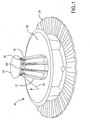
- an embodiment of an LED lamp 10 of the present invention includes a heat conductive post 12 having a base 14 and a top 16, a reflector 18 attached to base 14 and a heat sink 20 attached to base 14.
- the attachment of reflector 18 and heat sink 20 to base 14 is apparent from Figure 2 that shows lamp 10 with reflector 18 removed.
- Heat sink 20 may be any suitable material, such as cast zinc or aluminum.
- Suitable fasteners (such as shown in Figure 3) hold reflector 18 and heat sink 20 to base 14.
- the reflector, heat sink and fasteners shown in the figures are offered by way of example, with other designs, shapes, sizes and methods of attaching the reflector and heat sink being adaptable to the present invention as appropriate for a particular purpose, size and design of the lamp.
- LEDs 22 are mounted on a periphery of a head 24 that is on top 16 of post 12.
- Head 24 may include flat portions 24' for receiving LEDs 22.
- the number of LEDs 22 depends on the application for the lamp, and in one embodiment ten LEDs 22 are mounted on respective flat portions 24' around a periphery of head 24.
- Flat portions 24' preferably extend around head 24 in equal steps, and are angled with respect to the lamp axis generally to direct light from LEDs 22 to reflector 18 and not to the field to be illuminated.
- reflector 18 and LEDs 22 are arranged so that light from LEDs 22 is projected toward reflector 18 and reflected in a manner suitable for the purpose of lamp 10.
- a circuit board 28 with components for operating LEDs 22 may be carried at a bottom of base 14 and connected to LEDs 22 with electrical conductors 30.
- base 14 may be part of (or an extension of) a bottom of post 12 and head 24 may be part of (or an extension of) top 16 at the other end of post 12.
- the entirety of post 12, including base 14, top 16 and head 24 desirably is one piece of metal that has high thermal conductivity, such as cast zinc that may be metallized for aesthetics. Several parts could be joined to form post 12, but assembly would be more difficult and heat conduction may be impaired.
- Base 14 may be stepped to receive heat sink 20 and have appropriate connections and an O-ring 18' for securing reflector 18.
- Base 14 may have a central recess 32 therein that receives circuit board 28 (the circuitry not being shown as it is known to those of skill in the art).
- Recess 32 desirably has sufficient depth so that circuit board 28 does not protrude from the bottom of base 14.
- connection of LED 22 to circuit board 28 may be made by using LED assemblies 40 that each include an elongated substrate 42 with an LED 22 at a first end 44 thereof and electrical conductors 30 that extend from LED 22 to or beyond a second end 46 of substrate 42.
- Each LED assembly 40 may be separate and inserted into a separate wireway 48 in post 12 so that each LED 22 is placed in a heat conductive relationship with heat sink 20 through substrate 42 and post 12.
- Each flat portion 24' may have a separate wireway 48 leading thereto.
- each wireway 48 may be an axially extended slot with overhanging edges or projections forming retaining elements on the side walls of the slot.
- LED assembly 40 may slide into the slot axially with the edges of the LED assembly retained in the retaining elements.
- first end 44 When LED assembly 40 is inserted in wireway 48 from base 14 (first end 44 being inserted first in the preferred embodiment), first end 44 is bent as it approaches head 24 during insertion so that LED 22 assumes the proper projection angle.
- substrate 42 or at least a part thereof at first end 44, should be sufficiently flexible to bend during insertion.
- a suitable substrate material is electrically insulative, thermally conductive about and about 0.5 mm thick.
- Electrical conductors 30 may be metallized traces on substrate 42, wires, or other suitably flexible electrically conductive material.
- An insulative cover may be provided so that electrical conductors 30 do not contact walls of wireway 48 or the electrical conductors 30 may be offset from the wireway walls to avoid contact therewith.
- Figure 3 illustrates the fully inserted LED assembly 40 with first end 44 bent at head 24.
- First end 44 may be attached to head 24 (preferably to flat portion 24' of head 24 that has been given the proper angle) using an appropriate adhesive or by other means.
- each electrical conductor 30 has a conductive end 30' that extends beyond second end 46 of substrate 42.
- Conductive end 30' extends to circuit board 28 for connection thereto, or preferably extends entirely through circuit board 28, such as shown in Figure 3, so that electrical connections can be easily completed.
- Conductive ends 30' and its respective electrical conductor 30 may be a single element or may be two separate elements, with conductive end 30' being attached to electrical conductor 30.
- head 24 is removed from top 16 (such as indicated by dashed line 16') and LED assembly is inserted into top 16 (second end 46 being inserted first).
- first end 44 may be pre-bent or bent when head 24 is attached. Head 24 then may be press fit to top 16.
- FIG. 5 shows a cross section of post 12 with plural wireways 48.
- the number of LEDs may vary and the number of wireways 48 desirably corresponds to the number of LEDs.
- Each wireway 48 may be generally T-shaped in cross section with an open exterior slot 50 at a base of the T-shape and an interior cavity 52 that may be wider than slot 50 and defining a cap of the T-shape.
- LED assembly 40 may be carried in interior cavity 52 (the inwardly projecting walls defining the cavity being an example of the above-mentioned retaining element), or at a base of slot 50.
- wireway 48 may have side projections (e.g., fingers, bumps) from a side wall that hold LED assembly 40 therein.
- Slot 50 desirably is wider than respective electrical conductors 30 so that electrical conductors 30 avoid contact with post 12. Further, if LED assembly 40 is being inserted into base 14, slot 50 should also be wider than LED 22 to allow room for passage of LED 22 during insertion of LED assembly 40 into wireway 48.
- Interior cavity 52 may have a rear projection 54 therein that presses against a back of substrate 42 while the walls of cavity 52 press against the front.
- Rear projection 54 should assure a tight radial fit for substrate 42 so that there is good thermal conduction from LEDs 22 to post 12, which conducts heat to heat sink 20.
- Figure 6 is a more detailed view of the arrangement of first ends 44 of LED assemblies 40.
- the bending of first end 44, the relationship of slot 50 to electrical conductor 30, and an arrangement of LEDs 22 is illustrated by way of example.
- Figure 7 shows a part of the embodiment of Figure 6 with ghost images of LED assemblies 40 (as seen through head 24).
- the T-shaped wireways 48 and relative sizes of slot 50, electrical conductor 30, and LED 22 in this embodiment are also visible.
- Figures 8(a)-(b) show a sequence of assembly of an embodiment of the present invention, as seen from the bottom of base 14.
- Figure 8(a) are seen extensions of wireways 48 to base 14 (specifically, the openings of slots 50 and interior cavities 52 through base 14), second ends 46 of LED assemblies 40, and ends 30' of electrical conductors 30.
- LED assemblies 40 have been inserted into wireways 48.
- Head 24 may already be in place if LED assemblies 40 are inserted through bottom 14 or added later if LED assemblies 40 are inserted through top 16.
- Figure 8(b) illustrates the placement of circuit board 28 and the extension of ends 30' through circuit board 28 so as to facilitate electrical connection.
- Heat sink 20 and reflector 18 may be attached at an appropriate stage of assembly.
- the LED lamp and method described herein provides several production advantages. For example, individual LEDs need not be soldered to the post one by one.
- the LEDs and their electrical leads may be carried on substrates that can be pre-assembled and the pre-assembled substrates may be machine mounted in the post.
- the space for the circuit board may be sufficiently large to permit component separation and thermal dissipation, the connection of electrical leads to the circuit board can be highly automated, the heat sink may have a myriad of shapes as needed for particular applications, and the fit tolerance of the various parts may be set so that manufacturing cost and complexity can be reduced.
Landscapes
- Engineering & Computer Science (AREA)
- General Engineering & Computer Science (AREA)
- Physics & Mathematics (AREA)
- Microelectronics & Electronic Packaging (AREA)
- Optics & Photonics (AREA)
- Arrangement Of Elements, Cooling, Sealing, Or The Like Of Lighting Devices (AREA)
- Fastening Of Light Sources Or Lamp Holders (AREA)
- Non-Portable Lighting Devices Or Systems Thereof (AREA)
- Led Device Packages (AREA)
Abstract
Description
Claims (21)
- A lamp comprising:a heat conductive post having a bottom and a top and longitudinal recesses in an exterior of said post extending from the bottom to the top, said recesses defining plural wireways;plural light-emitting diode (LED) assemblies that each comprise a substrate with an LED at a first end thereof and an electrical conductor that extends from said LED to a second end of said substrate, each of said LED assemblies being in a different one of said wireways and in a heat conductive relationship with said post, the first end of said substrate being at the top of said post; anda circuit board that is at the bottom of said post and connected to said electrical conductor.
- The lamp of claim 1, wherein sides of each of said wireways has inward projections that hold a respective one of said LED assemblies.
- The lamp of claim 1, wherein each of said wireways is generally T-shaped in cross section with an open exterior slot at a base of the T-shape and an interior cavity wider than said slot defining a cap of the T-shape, and wherein said substrate is carried in said interior cavity.
- The lamp of claim 3, wherein said slot is wider than said electrical conductor.
- The lamp of claim 3, wherein said interior cavity has a projection therein that presses against a bottom of said substrate.
- The lamp of claim 1, wherein said first end of said substrate is bent relative to a remainder of said substrate.
- The lamp of claim 1, further comprising a reflector attached to the bottom of said post, and wherein each said LED faces said reflector so that light from each said LED is directed to and reflected from said reflector.
- The lamp of claim 1, further comprising a heat sink attached to the bottom of said post.
- The lamp of claim 1, wherein the bottom of said post has a hollow therein and said circuit board is in said hollow.
- The lamp of claim 1, wherein said electrical conductor comprises a wire that extends beyond said second end of said substrate and wherein said wire extends entirely through said circuit board.
- A lamp comprising:a thermally conductive base;a thermally conductive post having at least one slot with retaining elements, said post being in a thermally conductive relationship with said base;an LED mounted on a substrate, said substrate being retained in said at least one slot by said retaining elements with said LED adjacent to a top of said post, said LED being in a thermally conductive relationship with said post;said substrate further having an electrical connection for said LED that extends to a distal end of said substrate; anda circuit board retained in said base and electrically coupled to said electrical connection.
- The lamp of claim 11, wherein said at least one slot has a projection therein that presses against a bottom of said substrate.
- The lamp of claim 11, further comprising a reflector attached to said base and wherein said LED and said reflector are arranged so that light from said LED is reflected from said reflector.
- The lamp of claim 11, further comprising a heat sink attached to said base.
- A method of making a lamp, comprising the steps of:providing a heat conductive post having a bottom and a top and longitudinal recesses in an exterior of the post extending from the bottom to the top, the recesses defining plural wireways;inserting a different one of plural LED assemblies into each of the plural wireways so that each of the LED assemblies is in a heat conductive relationship with the post, each of the LED assemblies having a substrate with an LED at a first end thereof adjacent to the top of the post and an electrical conductor that extends from the LED to a second end of the substrate;mounting a circuit board for the LED assemblies at the bottom of the post; andconnecting each electrical conductor to the circuit board.
- The method of claim 15, wherein each of the LED assemblies is held in a respective one of the wireways with projections from sides of the respective one of the recesses that press against sides of the substrate.
- The method of claim 15, wherein each of the LED assemblies is held in a respective one of the wireways with a projection from a bottom of the respective one of the recesses that presses against a back of the substrate.
- The method of claim 15, wherein the first end of the substrate is initially inserted through the bottom of the post.
- The method of claim 18, wherein the inserting step comprises the step of bending the first end of the substrate relative to a remainder of the substrate when the first end reaches the top of the post during insertion.
- The method of claim 15 further comprising the step of attaching a reflector and a heat sink to the bottom of the post, the reflector and the LED being arranged so that light from the LED reflects from the reflector.
- The method of claim 15, further comprising the steps of providing a hollow at the bottom of the post and mounting the circuit board in the hollow.
Applications Claiming Priority (2)
| Application Number | Priority Date | Filing Date | Title |
|---|---|---|---|
| US647682 | 2003-08-25 | ||
| US10/647,682 US6955451B2 (en) | 2003-08-25 | 2003-08-25 | Lamp with LED substrates supported by heat conductive post, and method of making such lamp |
Publications (3)
| Publication Number | Publication Date |
|---|---|
| EP1510754A2 true EP1510754A2 (en) | 2005-03-02 |
| EP1510754A3 EP1510754A3 (en) | 2006-11-22 |
| EP1510754B1 EP1510754B1 (en) | 2008-12-24 |
Family
ID=34104652
Family Applications (1)
| Application Number | Title | Priority Date | Filing Date |
|---|---|---|---|
| EP04020009A Expired - Lifetime EP1510754B1 (en) | 2003-08-25 | 2004-08-24 | LED lamp with insertable LED substrates and method of making the lamp |
Country Status (6)
| Country | Link |
|---|---|
| US (1) | US6955451B2 (en) |
| EP (1) | EP1510754B1 (en) |
| JP (1) | JP2005072600A (en) |
| AT (1) | ATE418703T1 (en) |
| CA (1) | CA2471313C (en) |
| DE (1) | DE602004018582D1 (en) |
Cited By (6)
| Publication number | Priority date | Publication date | Assignee | Title |
|---|---|---|---|---|
| WO2008077627A1 (en) | 2006-12-22 | 2008-07-03 | Christoph Kuegler | Led lamp with omnidirectional light radiation and optimized heat dissipation |
| EP1760391A3 (en) * | 2005-08-31 | 2008-09-03 | Osram Sylvania Inc. | Light emitting diode lamp |
| WO2008122942A1 (en) * | 2007-04-05 | 2008-10-16 | Koninklijke Philips Electronics N.V. | Radiator and luminary |
| WO2011138363A1 (en) * | 2010-05-05 | 2011-11-10 | Alexiou & Tryde Holding Aps | Led lamp assembly |
| DE102010030296B4 (en) * | 2010-06-21 | 2012-11-22 | Osram Ag | Lamp with concave reflector and a projection for at least one light source |
| EP3144591A1 (en) * | 2015-09-18 | 2017-03-22 | Simon, S.A.U. | Heat sink |
Families Citing this family (38)
| Publication number | Priority date | Publication date | Assignee | Title |
|---|---|---|---|---|
| US20100173876A1 (en) * | 2000-12-19 | 2010-07-08 | The Board Of Regents Of The University Of Texas System | Oil-based nsaid compositions and methods for making and using same |
| US7008095B2 (en) * | 2003-04-10 | 2006-03-07 | Osram Sylvania Inc. | LED lamp with insertable axial wireways and method of making the lamp |
| US7964883B2 (en) * | 2004-02-26 | 2011-06-21 | Lighting Science Group Corporation | Light emitting diode package assembly that emulates the light pattern produced by an incandescent filament bulb |
| USD586751S1 (en) * | 2004-04-22 | 2009-02-17 | Osram Sylvania, Inc. | Light emitting diode bulb connector |
| USD619964S1 (en) * | 2004-04-22 | 2010-07-20 | Osram Sylvania, Inc. | Light emitting diode bulb connector |
| US7059748B2 (en) * | 2004-05-03 | 2006-06-13 | Osram Sylvania Inc. | LED bulb |
| USD610543S1 (en) * | 2004-04-22 | 2010-02-23 | Osram Sylvania, Inc. | Light emitting diode bulb connector |
| US7186010B2 (en) * | 2004-06-16 | 2007-03-06 | Osram Sylvania Inc. | LED lamp and lamp/reflector assembly |
| US7249877B2 (en) * | 2004-09-23 | 2007-07-31 | Osram Sylvania Inc. | Led lamp bulb assembly and reflector system |
| US20060146533A1 (en) * | 2005-01-03 | 2006-07-06 | Wen-Chieh Chen | Illuminating device for projector |
| EP1977456A4 (en) * | 2005-12-29 | 2014-03-05 | Lam Chiang Lim | HIGH POWER LIGHT EMITTING DIODE HOUSING FIXED REMOVABLE TO A HEAT SINK |
| US20080074885A1 (en) * | 2006-08-31 | 2008-03-27 | Brands David C | Led light unit |
| US7744259B2 (en) * | 2006-09-30 | 2010-06-29 | Ruud Lighting, Inc. | Directionally-adjustable LED spotlight |
| US7618163B2 (en) * | 2007-04-02 | 2009-11-17 | Ruud Lighting, Inc. | Light-directing LED apparatus |
| US7744250B2 (en) * | 2007-07-12 | 2010-06-29 | Fu Zhun Precision Industry (Shen Zhen) Co., Ltd. | LED lamp with a heat dissipation device |
| US20090073713A1 (en) * | 2007-09-07 | 2009-03-19 | Glovatsky Andrew Z | LED Multidimensional Printed Wiring Board Using Standoff Boards |
| US9423096B2 (en) | 2008-05-23 | 2016-08-23 | Cree, Inc. | LED lighting apparatus |
| US8348475B2 (en) | 2008-05-23 | 2013-01-08 | Ruud Lighting, Inc. | Lens with controlled backlight management |
| US8388193B2 (en) | 2008-05-23 | 2013-03-05 | Ruud Lighting, Inc. | Lens with TIR for off-axial light distribution |
| CN101614385B (en) * | 2008-06-27 | 2012-07-04 | 富准精密工业(深圳)有限公司 | LED lamp |
| US7841750B2 (en) | 2008-08-01 | 2010-11-30 | Ruud Lighting, Inc. | Light-directing lensing member with improved angled light distribution |
| US8109660B2 (en) * | 2008-08-07 | 2012-02-07 | Relume Technologies, Inc. | Globe deployable LED light assembly |
| US9255686B2 (en) | 2009-05-29 | 2016-02-09 | Cree, Inc. | Multi-lens LED-array optic system |
| US8152327B2 (en) * | 2009-10-02 | 2012-04-10 | Coast Cutlery Company | Focusing lens system |
| US8371710B2 (en) * | 2009-10-02 | 2013-02-12 | Coast Cutlery Company | Focusing lens system |
| US8330342B2 (en) * | 2009-12-21 | 2012-12-11 | Malek Bhairi | Spherical light output LED lens and heat sink stem system |
| US8550650B1 (en) | 2010-08-10 | 2013-10-08 | Patrick McGinty | Lighted helmet with heat pipe assembly |
| US8152341B2 (en) | 2011-02-04 | 2012-04-10 | Switch Bulb Company, Inc. | Expandable liquid volume in an LED bulb |
| US8686623B2 (en) * | 2012-02-01 | 2014-04-01 | Switch Bulb Company, Inc. | Omni-directional channeling of liquids for passive convection in LED bulbs |
| US10408429B2 (en) | 2012-02-29 | 2019-09-10 | Ideal Industries Lighting Llc | Lens for preferential-side distribution |
| US9541258B2 (en) | 2012-02-29 | 2017-01-10 | Cree, Inc. | Lens for wide lateral-angle distribution |
| US9541257B2 (en) | 2012-02-29 | 2017-01-10 | Cree, Inc. | Lens for primarily-elongate light distribution |
| USD697664S1 (en) | 2012-05-07 | 2014-01-14 | Cree, Inc. | LED lens |
| USD718490S1 (en) | 2013-03-15 | 2014-11-25 | Cree, Inc. | LED lens |
| US9523479B2 (en) | 2014-01-03 | 2016-12-20 | Cree, Inc. | LED lens |
| US9765956B2 (en) * | 2014-08-04 | 2017-09-19 | Spring City Electrical Manufacturing Company | LED luminaire light fixture for a lamppost |
| US10468566B2 (en) | 2017-04-10 | 2019-11-05 | Ideal Industries Lighting Llc | Hybrid lens for controlled light distribution |
| KR102124884B1 (en) | 2019-01-22 | 2020-06-23 | 주식회사 아이디스 | Fish eye camera |
Family Cites Families (7)
| Publication number | Priority date | Publication date | Assignee | Title |
|---|---|---|---|---|
| US6425678B1 (en) * | 1999-08-23 | 2002-07-30 | Dialight Corporation | Led obstruction lamp |
| DE20013605U1 (en) * | 2000-07-28 | 2000-12-28 | Opto-System GmbH, 12555 Berlin | Elongated light source |
| TW507858U (en) * | 2001-07-23 | 2002-10-21 | Lin Chau Tang | Energy saving lighting device with high illumination |
| US6682211B2 (en) * | 2001-09-28 | 2004-01-27 | Osram Sylvania Inc. | Replaceable LED lamp capsule |
| US6525668B1 (en) * | 2001-10-10 | 2003-02-25 | Twr Lighting, Inc. | LED array warning light system |
| DE20207745U1 (en) * | 2002-05-15 | 2002-09-05 | Ballaschk, Bernd, 03096 Burg | Heat regulating LED lamp |
| US6715900B2 (en) * | 2002-05-17 | 2004-04-06 | A L Lightech, Inc. | Light source arrangement |
-
2003
- 2003-08-25 US US10/647,682 patent/US6955451B2/en not_active Expired - Lifetime
-
2004
- 2004-06-17 CA CA2471313A patent/CA2471313C/en not_active Expired - Fee Related
- 2004-08-24 EP EP04020009A patent/EP1510754B1/en not_active Expired - Lifetime
- 2004-08-24 JP JP2004244101A patent/JP2005072600A/en not_active Withdrawn
- 2004-08-24 DE DE602004018582T patent/DE602004018582D1/en not_active Expired - Lifetime
- 2004-08-24 AT AT04020009T patent/ATE418703T1/en not_active IP Right Cessation
Cited By (9)
| Publication number | Priority date | Publication date | Assignee | Title |
|---|---|---|---|---|
| EP1760391A3 (en) * | 2005-08-31 | 2008-09-03 | Osram Sylvania Inc. | Light emitting diode lamp |
| WO2008077627A1 (en) | 2006-12-22 | 2008-07-03 | Christoph Kuegler | Led lamp with omnidirectional light radiation and optimized heat dissipation |
| CN101641551B (en) * | 2006-12-22 | 2012-08-29 | 克里斯多夫·库格雷 | LED light source with omnidirectional light emission and optimized heat dissipation |
| US8382320B2 (en) | 2006-12-22 | 2013-02-26 | Christoph Kuegler | Polyhedrally-shaped heat dissipating LED support |
| WO2008122942A1 (en) * | 2007-04-05 | 2008-10-16 | Koninklijke Philips Electronics N.V. | Radiator and luminary |
| WO2011138363A1 (en) * | 2010-05-05 | 2011-11-10 | Alexiou & Tryde Holding Aps | Led lamp assembly |
| US9121596B2 (en) | 2010-05-05 | 2015-09-01 | Alexiou & Tryde Holding Aps | LED lamp assembly |
| DE102010030296B4 (en) * | 2010-06-21 | 2012-11-22 | Osram Ag | Lamp with concave reflector and a projection for at least one light source |
| EP3144591A1 (en) * | 2015-09-18 | 2017-03-22 | Simon, S.A.U. | Heat sink |
Also Published As
| Publication number | Publication date |
|---|---|
| EP1510754B1 (en) | 2008-12-24 |
| JP2005072600A (en) | 2005-03-17 |
| EP1510754A3 (en) | 2006-11-22 |
| CA2471313A1 (en) | 2005-02-25 |
| DE602004018582D1 (en) | 2009-02-05 |
| US6955451B2 (en) | 2005-10-18 |
| US20050047145A1 (en) | 2005-03-03 |
| CA2471313C (en) | 2011-05-03 |
| ATE418703T1 (en) | 2009-01-15 |
Similar Documents
| Publication | Publication Date | Title |
|---|---|---|
| US6955451B2 (en) | Lamp with LED substrates supported by heat conductive post, and method of making such lamp | |
| US7111971B2 (en) | LED lamp with insertable axial wireways and method of making the lamp | |
| US7429186B2 (en) | Flexible high-power LED lighting system | |
| TWI518282B (en) | End cap assembly for a light tube | |
| CN101631989B (en) | Flexible high-power LED lighting system | |
| US20080253127A1 (en) | Led Lighting Module | |
| JP5665521B2 (en) | LED connector assembly and connector | |
| US20100210133A1 (en) | Illumination unit and wire harness equipped with the illumination unit | |
| JPH07106634A (en) | Light emitting diode module and light emitting diode light source | |
| CN111059482B (en) | Lighting device with lead frame | |
| US7025485B2 (en) | High mount stop lamp with printed circuit board | |
| US10584846B2 (en) | Lighting device with lens and method for production thereof | |
| KR100460838B1 (en) | Light | |
| JP5626874B2 (en) | Connector and lighting device | |
| JP5896125B2 (en) | Light emitting device and lighting device | |
| JPH10208515A (en) | Vehicle lighting | |
| CN210266764U (en) | Horizontal plug-in LED lights | |
| JP2013206851A (en) | Light-emitting device, lighting device, and lighting fixture | |
| US20200208790A1 (en) | Compact led lighting device and method for producing same | |
| JP3139079U (en) | LED unit and LED module | |
| JPH0140093Y2 (en) | ||
| JPH1050109A (en) | Vehicle lighting | |
| KR100571745B1 (en) | Fluorescent Lamp Socket for Signs | |
| US20080025040A1 (en) | LED light engine | |
| JP2014104918A (en) | In-vehicle light emitting device module |
Legal Events
| Date | Code | Title | Description |
|---|---|---|---|
| PUAI | Public reference made under article 153(3) epc to a published international application that has entered the european phase |
Free format text: ORIGINAL CODE: 0009012 |
|
| AK | Designated contracting states |
Kind code of ref document: A2 Designated state(s): AT BE BG CH CY CZ DE DK EE ES FI FR GB GR HU IE IT LI LU MC NL PL PT RO SE SI SK TR |
|
| AX | Request for extension of the european patent |
Extension state: AL HR LT LV MK |
|
| PUAL | Search report despatched |
Free format text: ORIGINAL CODE: 0009013 |
|
| AK | Designated contracting states |
Kind code of ref document: A3 Designated state(s): AT BE BG CH CY CZ DE DK EE ES FI FR GB GR HU IE IT LI LU MC NL PL PT RO SE SI SK TR |
|
| AX | Request for extension of the european patent |
Extension state: AL HR LT LV MK |
|
| 17P | Request for examination filed |
Effective date: 20070516 |
|
| AKX | Designation fees paid |
Designated state(s): AT BE BG CH CY CZ DE DK EE ES FI FR GB GR HU IE IT LI LU MC NL PL PT RO SE SI SK TR |
|
| 17Q | First examination report despatched |
Effective date: 20071022 |
|
| GRAP | Despatch of communication of intention to grant a patent |
Free format text: ORIGINAL CODE: EPIDOSNIGR1 |
|
| GRAS | Grant fee paid |
Free format text: ORIGINAL CODE: EPIDOSNIGR3 |
|
| GRAA | (expected) grant |
Free format text: ORIGINAL CODE: 0009210 |
|
| AK | Designated contracting states |
Kind code of ref document: B1 Designated state(s): AT BE BG CH CY CZ DE DK EE ES FI FR GB GR HU IE IT LI LU MC NL PL PT RO SE SI SK TR |
|
| REG | Reference to a national code |
Ref country code: GB Ref legal event code: FG4D |
|
| REG | Reference to a national code |
Ref country code: CH Ref legal event code: EP |
|
| REG | Reference to a national code |
Ref country code: IE Ref legal event code: FG4D |
|
| REF | Corresponds to: |
Ref document number: 602004018582 Country of ref document: DE Date of ref document: 20090205 Kind code of ref document: P |
|
| PG25 | Lapsed in a contracting state [announced via postgrant information from national office to epo] |
Ref country code: SI Free format text: LAPSE BECAUSE OF FAILURE TO SUBMIT A TRANSLATION OF THE DESCRIPTION OR TO PAY THE FEE WITHIN THE PRESCRIBED TIME-LIMIT Effective date: 20081224 Ref country code: PL Free format text: LAPSE BECAUSE OF FAILURE TO SUBMIT A TRANSLATION OF THE DESCRIPTION OR TO PAY THE FEE WITHIN THE PRESCRIBED TIME-LIMIT Effective date: 20081224 Ref country code: NL Free format text: LAPSE BECAUSE OF FAILURE TO SUBMIT A TRANSLATION OF THE DESCRIPTION OR TO PAY THE FEE WITHIN THE PRESCRIBED TIME-LIMIT Effective date: 20081224 Ref country code: FI Free format text: LAPSE BECAUSE OF FAILURE TO SUBMIT A TRANSLATION OF THE DESCRIPTION OR TO PAY THE FEE WITHIN THE PRESCRIBED TIME-LIMIT Effective date: 20081224 |
|
| NLV1 | Nl: lapsed or annulled due to failure to fulfill the requirements of art. 29p and 29m of the patents act | ||
| PG25 | Lapsed in a contracting state [announced via postgrant information from national office to epo] |
Ref country code: ES Free format text: LAPSE BECAUSE OF FAILURE TO SUBMIT A TRANSLATION OF THE DESCRIPTION OR TO PAY THE FEE WITHIN THE PRESCRIBED TIME-LIMIT Effective date: 20090404 Ref country code: EE Free format text: LAPSE BECAUSE OF FAILURE TO SUBMIT A TRANSLATION OF THE DESCRIPTION OR TO PAY THE FEE WITHIN THE PRESCRIBED TIME-LIMIT Effective date: 20081224 Ref country code: BG Free format text: LAPSE BECAUSE OF FAILURE TO SUBMIT A TRANSLATION OF THE DESCRIPTION OR TO PAY THE FEE WITHIN THE PRESCRIBED TIME-LIMIT Effective date: 20090324 Ref country code: RO Free format text: LAPSE BECAUSE OF FAILURE TO SUBMIT A TRANSLATION OF THE DESCRIPTION OR TO PAY THE FEE WITHIN THE PRESCRIBED TIME-LIMIT Effective date: 20081224 Ref country code: BE Free format text: LAPSE BECAUSE OF FAILURE TO SUBMIT A TRANSLATION OF THE DESCRIPTION OR TO PAY THE FEE WITHIN THE PRESCRIBED TIME-LIMIT Effective date: 20081224 |
|
| PG25 | Lapsed in a contracting state [announced via postgrant information from national office to epo] |
Ref country code: CZ Free format text: LAPSE BECAUSE OF FAILURE TO SUBMIT A TRANSLATION OF THE DESCRIPTION OR TO PAY THE FEE WITHIN THE PRESCRIBED TIME-LIMIT Effective date: 20081224 Ref country code: SE Free format text: LAPSE BECAUSE OF FAILURE TO SUBMIT A TRANSLATION OF THE DESCRIPTION OR TO PAY THE FEE WITHIN THE PRESCRIBED TIME-LIMIT Effective date: 20090324 Ref country code: PT Free format text: LAPSE BECAUSE OF FAILURE TO SUBMIT A TRANSLATION OF THE DESCRIPTION OR TO PAY THE FEE WITHIN THE PRESCRIBED TIME-LIMIT Effective date: 20090525 Ref country code: AT Free format text: LAPSE BECAUSE OF FAILURE TO SUBMIT A TRANSLATION OF THE DESCRIPTION OR TO PAY THE FEE WITHIN THE PRESCRIBED TIME-LIMIT Effective date: 20081224 |
|
| PG25 | Lapsed in a contracting state [announced via postgrant information from national office to epo] |
Ref country code: SK Free format text: LAPSE BECAUSE OF FAILURE TO SUBMIT A TRANSLATION OF THE DESCRIPTION OR TO PAY THE FEE WITHIN THE PRESCRIBED TIME-LIMIT Effective date: 20081224 |
|
| PG25 | Lapsed in a contracting state [announced via postgrant information from national office to epo] |
Ref country code: DK Free format text: LAPSE BECAUSE OF FAILURE TO SUBMIT A TRANSLATION OF THE DESCRIPTION OR TO PAY THE FEE WITHIN THE PRESCRIBED TIME-LIMIT Effective date: 20081224 |
|
| PLBE | No opposition filed within time limit |
Free format text: ORIGINAL CODE: 0009261 |
|
| STAA | Information on the status of an ep patent application or granted ep patent |
Free format text: STATUS: NO OPPOSITION FILED WITHIN TIME LIMIT |
|
| 26N | No opposition filed |
Effective date: 20090925 |
|
| PG25 | Lapsed in a contracting state [announced via postgrant information from national office to epo] |
Ref country code: MC Free format text: LAPSE BECAUSE OF NON-PAYMENT OF DUE FEES Effective date: 20090831 |
|
| REG | Reference to a national code |
Ref country code: CH Ref legal event code: PL |
|
| PG25 | Lapsed in a contracting state [announced via postgrant information from national office to epo] |
Ref country code: LI Free format text: LAPSE BECAUSE OF NON-PAYMENT OF DUE FEES Effective date: 20090831 Ref country code: CH Free format text: LAPSE BECAUSE OF NON-PAYMENT OF DUE FEES Effective date: 20090831 |
|
| PG25 | Lapsed in a contracting state [announced via postgrant information from national office to epo] |
Ref country code: IE Free format text: LAPSE BECAUSE OF NON-PAYMENT OF DUE FEES Effective date: 20090824 |
|
| PG25 | Lapsed in a contracting state [announced via postgrant information from national office to epo] |
Ref country code: GR Free format text: LAPSE BECAUSE OF FAILURE TO SUBMIT A TRANSLATION OF THE DESCRIPTION OR TO PAY THE FEE WITHIN THE PRESCRIBED TIME-LIMIT Effective date: 20090325 |
|
| PG25 | Lapsed in a contracting state [announced via postgrant information from national office to epo] |
Ref country code: IT Free format text: LAPSE BECAUSE OF FAILURE TO SUBMIT A TRANSLATION OF THE DESCRIPTION OR TO PAY THE FEE WITHIN THE PRESCRIBED TIME-LIMIT Effective date: 20081224 |
|
| PG25 | Lapsed in a contracting state [announced via postgrant information from national office to epo] |
Ref country code: LU Free format text: LAPSE BECAUSE OF NON-PAYMENT OF DUE FEES Effective date: 20090824 |
|
| PG25 | Lapsed in a contracting state [announced via postgrant information from national office to epo] |
Ref country code: HU Free format text: LAPSE BECAUSE OF FAILURE TO SUBMIT A TRANSLATION OF THE DESCRIPTION OR TO PAY THE FEE WITHIN THE PRESCRIBED TIME-LIMIT Effective date: 20090625 |
|
| PG25 | Lapsed in a contracting state [announced via postgrant information from national office to epo] |
Ref country code: TR Free format text: LAPSE BECAUSE OF FAILURE TO SUBMIT A TRANSLATION OF THE DESCRIPTION OR TO PAY THE FEE WITHIN THE PRESCRIBED TIME-LIMIT Effective date: 20081224 |
|
| PG25 | Lapsed in a contracting state [announced via postgrant information from national office to epo] |
Ref country code: CY Free format text: LAPSE BECAUSE OF FAILURE TO SUBMIT A TRANSLATION OF THE DESCRIPTION OR TO PAY THE FEE WITHIN THE PRESCRIBED TIME-LIMIT Effective date: 20081224 |
|
| REG | Reference to a national code |
Ref country code: FR Ref legal event code: PLFP Year of fee payment: 13 |
|
| REG | Reference to a national code |
Ref country code: FR Ref legal event code: PLFP Year of fee payment: 14 |
|
| REG | Reference to a national code |
Ref country code: FR Ref legal event code: PLFP Year of fee payment: 15 |
|
| PGFP | Annual fee paid to national office [announced via postgrant information from national office to epo] |
Ref country code: FR Payment date: 20180827 Year of fee payment: 15 Ref country code: DE Payment date: 20180823 Year of fee payment: 15 |
|
| PGFP | Annual fee paid to national office [announced via postgrant information from national office to epo] |
Ref country code: GB Payment date: 20180822 Year of fee payment: 15 |
|
| REG | Reference to a national code |
Ref country code: DE Ref legal event code: R119 Ref document number: 602004018582 Country of ref document: DE |
|
| GBPC | Gb: european patent ceased through non-payment of renewal fee |
Effective date: 20190824 |
|
| PG25 | Lapsed in a contracting state [announced via postgrant information from national office to epo] |
Ref country code: FR Free format text: LAPSE BECAUSE OF NON-PAYMENT OF DUE FEES Effective date: 20190831 Ref country code: DE Free format text: LAPSE BECAUSE OF NON-PAYMENT OF DUE FEES Effective date: 20200303 |
|
| PG25 | Lapsed in a contracting state [announced via postgrant information from national office to epo] |
Ref country code: GB Free format text: LAPSE BECAUSE OF NON-PAYMENT OF DUE FEES Effective date: 20190824 |