EP1376846B1 - Device for the displacement of small volumes of liquid along a micro-catenary using electrostatic forces - Google Patents
Device for the displacement of small volumes of liquid along a micro-catenary using electrostatic forces Download PDFInfo
- Publication number
- EP1376846B1 EP1376846B1 EP03101771A EP03101771A EP1376846B1 EP 1376846 B1 EP1376846 B1 EP 1376846B1 EP 03101771 A EP03101771 A EP 03101771A EP 03101771 A EP03101771 A EP 03101771A EP 1376846 B1 EP1376846 B1 EP 1376846B1
- Authority
- EP
- European Patent Office
- Prior art keywords
- substrate
- liquid
- conducting wire
- micro
- small
- Prior art date
- Legal status (The legal status is an assumption and is not a legal conclusion. Google has not performed a legal analysis and makes no representation as to the accuracy of the status listed.)
- Expired - Lifetime
Links
- 239000007788 liquid Substances 0.000 title claims abstract description 104
- 238000006073 displacement reaction Methods 0.000 title claims description 24
- 239000000758 substrate Substances 0.000 claims abstract description 97
- 238000009736 wetting Methods 0.000 claims description 25
- 230000000694 effects Effects 0.000 claims description 7
- 230000002209 hydrophobic effect Effects 0.000 claims description 5
- 238000010438 heat treatment Methods 0.000 claims description 4
- 238000012546 transfer Methods 0.000 claims description 4
- 239000012777 electrically insulating material Substances 0.000 claims description 2
- 238000005259 measurement Methods 0.000 claims description 2
- 239000011159 matrix material Substances 0.000 claims 2
- 238000000034 method Methods 0.000 abstract description 14
- 239000004020 conductor Substances 0.000 abstract description 9
- 230000004913 activation Effects 0.000 description 12
- 238000004519 manufacturing process Methods 0.000 description 10
- 125000006850 spacer group Chemical group 0.000 description 8
- XUIMIQQOPSSXEZ-UHFFFAOYSA-N Silicon Chemical compound [Si] XUIMIQQOPSSXEZ-UHFFFAOYSA-N 0.000 description 7
- 239000012530 fluid Substances 0.000 description 7
- 230000006870 function Effects 0.000 description 7
- 239000010703 silicon Substances 0.000 description 7
- 229910052710 silicon Inorganic materials 0.000 description 7
- PCHJSUWPFVWCPO-UHFFFAOYSA-N gold Chemical compound [Au] PCHJSUWPFVWCPO-UHFFFAOYSA-N 0.000 description 6
- VYPSYNLAJGMNEJ-UHFFFAOYSA-N Silicium dioxide Chemical compound O=[Si]=O VYPSYNLAJGMNEJ-UHFFFAOYSA-N 0.000 description 5
- 229910052782 aluminium Inorganic materials 0.000 description 5
- XAGFODPZIPBFFR-UHFFFAOYSA-N aluminium Chemical compound [Al] XAGFODPZIPBFFR-UHFFFAOYSA-N 0.000 description 5
- 230000008901 benefit Effects 0.000 description 5
- 239000011810 insulating material Substances 0.000 description 5
- 238000000206 photolithography Methods 0.000 description 5
- 230000005684 electric field Effects 0.000 description 4
- 229910052737 gold Inorganic materials 0.000 description 4
- 239000010931 gold Substances 0.000 description 4
- 239000000463 material Substances 0.000 description 4
- 230000008569 process Effects 0.000 description 4
- XLYOFNOQVPJJNP-UHFFFAOYSA-N water Substances O XLYOFNOQVPJJNP-UHFFFAOYSA-N 0.000 description 4
- 238000010521 absorption reaction Methods 0.000 description 3
- 239000002313 adhesive film Substances 0.000 description 3
- 230000005484 gravity Effects 0.000 description 3
- 239000003921 oil Substances 0.000 description 3
- 229910052814 silicon oxide Inorganic materials 0.000 description 3
- 239000000126 substance Substances 0.000 description 3
- 241000135309 Processus Species 0.000 description 2
- 229920006362 Teflon® Polymers 0.000 description 2
- 230000003213 activating effect Effects 0.000 description 2
- 238000004458 analytical method Methods 0.000 description 2
- 238000006243 chemical reaction Methods 0.000 description 2
- 230000003292 diminished effect Effects 0.000 description 2
- 230000005686 electrostatic field Effects 0.000 description 2
- 238000005516 engineering process Methods 0.000 description 2
- 238000005530 etching Methods 0.000 description 2
- 230000008020 evaporation Effects 0.000 description 2
- 238000001704 evaporation Methods 0.000 description 2
- 239000011521 glass Substances 0.000 description 2
- 238000002347 injection Methods 0.000 description 2
- 239000007924 injection Substances 0.000 description 2
- 239000012212 insulator Substances 0.000 description 2
- 230000003993 interaction Effects 0.000 description 2
- 238000004377 microelectronic Methods 0.000 description 2
- 239000004033 plastic Substances 0.000 description 2
- BASFCYQUMIYNBI-UHFFFAOYSA-N platinum Chemical compound [Pt] BASFCYQUMIYNBI-UHFFFAOYSA-N 0.000 description 2
- 229920005989 resin Polymers 0.000 description 2
- 239000011347 resin Substances 0.000 description 2
- 230000002441 reversible effect Effects 0.000 description 2
- 238000004381 surface treatment Methods 0.000 description 2
- 238000003466 welding Methods 0.000 description 2
- KHNSAJUYVQRLBO-UHFFFAOYSA-N 4-[chloro(dimethoxy)silyl]oxybutan-1-amine Chemical compound CO[Si](Cl)(OC)OCCCCN KHNSAJUYVQRLBO-UHFFFAOYSA-N 0.000 description 1
- 201000005569 Gout Diseases 0.000 description 1
- 229910052581 Si3N4 Inorganic materials 0.000 description 1
- 229910004298 SiO 2 Inorganic materials 0.000 description 1
- BLRPTPMANUNPDV-UHFFFAOYSA-N Silane Chemical compound [SiH4] BLRPTPMANUNPDV-UHFFFAOYSA-N 0.000 description 1
- 239000007864 aqueous solution Substances 0.000 description 1
- 239000011324 bead Substances 0.000 description 1
- 239000000919 ceramic Substances 0.000 description 1
- 238000003486 chemical etching Methods 0.000 description 1
- 239000003153 chemical reaction reagent Substances 0.000 description 1
- 238000007796 conventional method Methods 0.000 description 1
- 230000001351 cycling effect Effects 0.000 description 1
- 238000009826 distribution Methods 0.000 description 1
- 238000000203 droplet dispensing Methods 0.000 description 1
- 239000003792 electrolyte Substances 0.000 description 1
- 229940082150 encore Drugs 0.000 description 1
- 239000003822 epoxy resin Substances 0.000 description 1
- 230000002349 favourable effect Effects 0.000 description 1
- 239000000835 fiber Substances 0.000 description 1
- 238000009472 formulation Methods 0.000 description 1
- 230000002427 irreversible effect Effects 0.000 description 1
- 238000002032 lab-on-a-chip Methods 0.000 description 1
- QSHDDOUJBYECFT-UHFFFAOYSA-N mercury Chemical compound [Hg] QSHDDOUJBYECFT-UHFFFAOYSA-N 0.000 description 1
- 229910052753 mercury Inorganic materials 0.000 description 1
- 238000005459 micromachining Methods 0.000 description 1
- 239000000203 mixture Substances 0.000 description 1
- 229910021421 monocrystalline silicon Inorganic materials 0.000 description 1
- 150000004767 nitrides Chemical class 0.000 description 1
- 238000000623 plasma-assisted chemical vapour deposition Methods 0.000 description 1
- 229910052697 platinum Inorganic materials 0.000 description 1
- 229920000052 poly(p-xylylene) Polymers 0.000 description 1
- 229920000647 polyepoxide Polymers 0.000 description 1
- 238000012552 review Methods 0.000 description 1
- 230000035945 sensitivity Effects 0.000 description 1
- 229910000077 silane Inorganic materials 0.000 description 1
- 239000000377 silicon dioxide Substances 0.000 description 1
- HQVNEWCFYHHQES-UHFFFAOYSA-N silicon nitride Chemical compound N12[Si]34N5[Si]62N3[Si]51N64 HQVNEWCFYHHQES-UHFFFAOYSA-N 0.000 description 1
- 239000007787 solid Substances 0.000 description 1
- 239000000243 solution Substances 0.000 description 1
- 238000003892 spreading Methods 0.000 description 1
- 230000007480 spreading Effects 0.000 description 1
- 238000003860 storage Methods 0.000 description 1
- 230000003075 superhydrophobic effect Effects 0.000 description 1
Images


Classifications
-
- H—ELECTRICITY
- H02—GENERATION; CONVERSION OR DISTRIBUTION OF ELECTRIC POWER
- H02N—ELECTRIC MACHINES NOT OTHERWISE PROVIDED FOR
- H02N11/00—Generators or motors not provided for elsewhere; Alleged perpetua mobilia obtained by electric or magnetic means
- H02N11/006—Motors
-
- B—PERFORMING OPERATIONS; TRANSPORTING
- B01—PHYSICAL OR CHEMICAL PROCESSES OR APPARATUS IN GENERAL
- B01L—CHEMICAL OR PHYSICAL LABORATORY APPARATUS FOR GENERAL USE
- B01L3/00—Containers or dishes for laboratory use, e.g. laboratory glassware; Droppers
- B01L3/50—Containers for the purpose of retaining a material to be analysed, e.g. test tubes
- B01L3/502—Containers for the purpose of retaining a material to be analysed, e.g. test tubes with fluid transport, e.g. in multi-compartment structures
- B01L3/5027—Containers for the purpose of retaining a material to be analysed, e.g. test tubes with fluid transport, e.g. in multi-compartment structures by integrated microfluidic structures, i.e. dimensions of channels and chambers are such that surface tension forces are important, e.g. lab-on-a-chip
- B01L3/502769—Containers for the purpose of retaining a material to be analysed, e.g. test tubes with fluid transport, e.g. in multi-compartment structures by integrated microfluidic structures, i.e. dimensions of channels and chambers are such that surface tension forces are important, e.g. lab-on-a-chip characterised by multiphase flow arrangements
- B01L3/502784—Containers for the purpose of retaining a material to be analysed, e.g. test tubes with fluid transport, e.g. in multi-compartment structures by integrated microfluidic structures, i.e. dimensions of channels and chambers are such that surface tension forces are important, e.g. lab-on-a-chip characterised by multiphase flow arrangements specially adapted for droplet or plug flow, e.g. digital microfluidics
- B01L3/502792—Containers for the purpose of retaining a material to be analysed, e.g. test tubes with fluid transport, e.g. in multi-compartment structures by integrated microfluidic structures, i.e. dimensions of channels and chambers are such that surface tension forces are important, e.g. lab-on-a-chip characterised by multiphase flow arrangements specially adapted for droplet or plug flow, e.g. digital microfluidics for moving individual droplets on a plate, e.g. by locally altering surface tension
-
- F—MECHANICAL ENGINEERING; LIGHTING; HEATING; WEAPONS; BLASTING
- F04—POSITIVE - DISPLACEMENT MACHINES FOR LIQUIDS; PUMPS FOR LIQUIDS OR ELASTIC FLUIDS
- F04B—POSITIVE-DISPLACEMENT MACHINES FOR LIQUIDS; PUMPS
- F04B17/00—Pumps characterised by combination with, or adaptation to, specific driving engines or motors
-
- F—MECHANICAL ENGINEERING; LIGHTING; HEATING; WEAPONS; BLASTING
- F04—POSITIVE - DISPLACEMENT MACHINES FOR LIQUIDS; PUMPS FOR LIQUIDS OR ELASTIC FLUIDS
- F04B—POSITIVE-DISPLACEMENT MACHINES FOR LIQUIDS; PUMPS
- F04B19/00—Machines or pumps having pertinent characteristics not provided for in, or of interest apart from, groups F04B1/00 - F04B17/00
- F04B19/006—Micropumps
-
- B—PERFORMING OPERATIONS; TRANSPORTING
- B01—PHYSICAL OR CHEMICAL PROCESSES OR APPARATUS IN GENERAL
- B01L—CHEMICAL OR PHYSICAL LABORATORY APPARATUS FOR GENERAL USE
- B01L2300/00—Additional constructional details
- B01L2300/08—Geometry, shape and general structure
- B01L2300/0832—Geometry, shape and general structure cylindrical, tube shaped
- B01L2300/0845—Filaments, strings, fibres, i.e. not hollow
-
- B—PERFORMING OPERATIONS; TRANSPORTING
- B01—PHYSICAL OR CHEMICAL PROCESSES OR APPARATUS IN GENERAL
- B01L—CHEMICAL OR PHYSICAL LABORATORY APPARATUS FOR GENERAL USE
- B01L2300/00—Additional constructional details
- B01L2300/08—Geometry, shape and general structure
- B01L2300/089—Virtual walls for guiding liquids
-
- B—PERFORMING OPERATIONS; TRANSPORTING
- B01—PHYSICAL OR CHEMICAL PROCESSES OR APPARATUS IN GENERAL
- B01L—CHEMICAL OR PHYSICAL LABORATORY APPARATUS FOR GENERAL USE
- B01L2300/00—Additional constructional details
- B01L2300/18—Means for temperature control
- B01L2300/1805—Conductive heating, heat from thermostatted solids is conducted to receptacles, e.g. heating plates, blocks
- B01L2300/1827—Conductive heating, heat from thermostatted solids is conducted to receptacles, e.g. heating plates, blocks using resistive heater
-
- B—PERFORMING OPERATIONS; TRANSPORTING
- B01—PHYSICAL OR CHEMICAL PROCESSES OR APPARATUS IN GENERAL
- B01L—CHEMICAL OR PHYSICAL LABORATORY APPARATUS FOR GENERAL USE
- B01L2400/00—Moving or stopping fluids
- B01L2400/04—Moving fluids with specific forces or mechanical means
- B01L2400/0403—Moving fluids with specific forces or mechanical means specific forces
- B01L2400/0415—Moving fluids with specific forces or mechanical means specific forces electrical forces, e.g. electrokinetic
-
- G—PHYSICS
- G01—MEASURING; TESTING
- G01N—INVESTIGATING OR ANALYSING MATERIALS BY DETERMINING THEIR CHEMICAL OR PHYSICAL PROPERTIES
- G01N35/00—Automatic analysis not limited to methods or materials provided for in any single one of groups G01N1/00 - G01N33/00; Handling materials therefor
- G01N35/10—Devices for transferring samples or any liquids to, in, or from, the analysis apparatus, e.g. suction devices, injection devices
- G01N2035/1027—General features of the devices
- G01N2035/1034—Transferring microquantities of liquid
- G01N2035/1046—Levitated, suspended drops
Definitions
- the invention relates to a device for handling drops of small volumes of a few nanoliters, a few microliters.
- the displacement device uses electrostatic forces to move small volumes of liquid.
- micro-fluidics in micro-channels Another difficulty of micro-fluidics in micro-channels is having to connect the component with the outside world.
- the connection of capillaries to a micro-component is one of the difficulties encountered in the realization of laboratories on a chip.
- it is necessary to be able to manage the inputs / outputs of the different liquids from or to the external fluid storage systems while limiting the dead volumes.
- Another method of moving small volumes of fluid is to manipulate an interface between two immiscible fluids.
- the document FR-A-2 548 431 discloses a device for electric control of displacement of dielectric liquid.
- a drop of liquid is placed between two planes comprising pairs of electrodes.
- the drop of liquid has a permittivity greater than its environment defined by the space between the two planes comprising the electrodes.
- the displacement is electrically controlled by applying electrical voltages to the electrode pairs.
- the displacement is explained by the existence of a dielectric force resulting from a difference in permittivity between the droplet and its environment and by electric field gradients which result from the applied voltages.
- the dielectric strength tends to attract the fluid having the highest permittivity to the areas where the field is the most intense. This force is able to overcome the forces of superficial tension which explains the displacement of gout.
- a silane surface treatment (aminopropyltrimethoxysilyl chloride) is used to make the surfaces slightly wetting.
- Electrocapillarity has long been studied (Lippman, 1875). A formulation can be found in the article "Electrocapillarity and Wetting of Insulating Films by Water” by Bruno Berge, CR Acad. Sci. Paris, t.317, series II, pages 157-153, 1993. A drop of non-dielectric liquid is deposited on a substrate comprising an electrode covered with an insulator. A second electrode is immersed in the drop. The drop spreads when a voltage is applied between the two electrodes.
- the disadvantage of the devices described above is to have to confine the drops between two planes or in a channel. This makes the assembly and use of the complex component. We find the problems of capillary connections that have already been identified for micro-fluidics in channels with more electrical connections to take into account. There are also the risks of absorption phenomena of biological entities on both planes confining the drops.
- the system is in this case open.
- a drop is directly deposited on a surface.
- the surface comprises a plurality of interdigitated electrodes covered with an insulating layer.
- the surface is rendered very hydrophobic.
- Activation is based on the presence of electrostatic forces generated by the electrodes placed under the drop.
- the Maxwell stress distribution is modified on the surface of the drop and Mr. Washizu has shown that this electrostatic pressure can cause the drop to move.
- the present invention has been designed to overcome the disadvantages presented by the devices of the prior art.
- a device for moving at least a small volume of liquid under the effect of an electrical control comprising a substrate provided with first electrically conductive means, the device also comprising second electrically conductive means arranged vis-à-vis the first electrically conductive means, the first electrically conductive means and the second means electrically conductive conductors connectable to electrical supply means to allow the application of electrostatic forces to the small volume of liquid, characterized in that the second electrically conductive means comprise at least one conductive wire arranged parallel to the substrate and at a determined distance of the substrate to allow movement of the small volume of liquid along said conductive wire under the effect of applied electrostatic forces.
- the main purpose of the conducting wire, or micro-catenary is to play the role of an electrode. It also presents a second function which is to guide small volumes of liquid. Indeed, thanks to the capillary forces, a drop on the micro-catenary tends to stay in contact with this wire which thus ensures the guiding function during the possible movement of the drop.
- the device according to the invention can deform or move a small volume of liquid by applying a continuous or alternating electric field between the micro-catenary and the first electrically conductive means.
- the movement of small volumes of liquid can be explained by reference to the prior art cited above and describing the electrostatic forces.
- the first electrically conductive means comprise electrodes arranged on a nonelectrically conductive surface of the substrate and aligned in the direction of the conductive wire.
- the conductive wire is wetting for the liquid of the small volume of liquid. This allows better guidance of the small volume of liquid by the micro-catenary.
- the first electrically conductive means and / or the second electrically conductive means are covered with a layer of electrically insulating material. This allows, in the case where the liquid to be moved is electrically conductive, to interpose an insulating layer so as not to create intense electric currents through the drop of liquid.
- the device comprises an ambient environment in which the small volume of liquid moves, this ambient medium consisting of a gas or a liquid immiscible with the small volume of liquid.
- this ambient medium may be an oil bath. This avoids evaporation of the liquid when a long, high temperature protocol is applied.
- the determined distance between the conductive wire and the substrate is such that the small volume of liquid is, in the absence of electrostatic forces applied, in contact with the substrate, the substrate providing a non-wetting contact with the liquid of the small volume of liquid.
- the determined distance between the conducting wire and the substrate and the diameter of the conducting wire are such that the small volume of liquid is not, in the absence of applied electrostatic forces, in contact with the substrate .
- the conductive wire being disposed below the substrate, the determined distance between the conductive wire and the substrate may be such that a first value of applied electrostatic forces causes contact between the small volume of liquid and the substrate.
- the substrate can then provide a wetting contact to the small volume of liquid so as to transfer the small volume of liquid to the substrate when the applied electrostatic forces are canceled or sufficiently diminished.
- the substrate may also provide hydrophobic contact to the small volume of liquid so that the small volume of liquid is supported only by the lead when the applied electrostatic forces are canceled or sufficiently diminished.
- the determined distance between the conducting wire and the substrate and the diameter of the conducting wire are such that the small volume of liquid is not, in the presence of applied electrostatic displacement forces, in contact with the substrate .
- the device may comprise means for self-aligning and self-positioning the conductive wire with means for feeding and / or evacuation of the small volume of liquid.
- the means for supplying and / or evacuating the small volume of liquid comprise at least one micro-capillary.
- the substrate provides the small volume of liquid with an asymmetric roughness surface, the distance between the conductive wire and the substrate being such that, under the effect of electrostatic forces applied, the small volume of liquid is contact of the substrate which, by its asymmetrical roughness surface, promotes the displacement of the small volume of liquid.
- the asymmetrical roughness surface can have a factory roof profile.
- the surface offered by the substrate to the small volume of liquid may advantageously be non-wetting.
- the first conductive means may comprise an array of electrodes forming lines and columns, the second electrically conductive means comprising conductive wires, with each line of electrodes corresponding to a conductive wire.
- the first conductive means may also comprise an array of electrodes forming lines and columns, the second electrically conductive means comprising a first series of conductive wires and a second series of conductive wires, at each electrode line corresponding a conductive wire of the first series of conductive wires, to each corresponding electrode column a conductive wire of the second series of conductive wires.
- the device may comprise means for heating the conductive wire or possibly the conductive wires.
- the heating means may be electrical means for the circulation of an electric current in the conductor (s) wire (s).
- the device comprises means for controlling the temperature of the conductor wire (s) from the measurement of the electrical resistance of the conductor wire (s).
- FIG. 1 A first variant of the invention is shown in FIG. 1.
- the device shown which may be called a chip, comprises a planar substrate 1, preferably of insulating material.
- One of the faces of the substrate 1 comprises electrodes 2 aligned in the direction intended for the displacement of the micro-drops.
- a conductive wire 3 or micro-catenary is disposed substantially parallel to the substrate 1 and at a distance determined with respect to this substrate.
- the micro-catenary 3 is located vis-à-vis the electrodes 2.
- the assembly is immersed in an ambient environment 4 which can be a gas or a liquid immiscible with the liquid of the microdrop 5.
- the device according to the invention can deform or move the drop 5 by applying an electric field between the micro-catenary and at least one of the electrodes 2.
- the displacement of the drop can be explained by making reference to the prior art cited above and which concerns the electrostatic forces.
- the micro-catenary 3 providing a guiding function for the drop during its movement, it is preferable that it is wetting for the liquid forming the drop.
- the liquid forming the drop is electrically conductive, it is preferable to cover the electrodes 2 with an insulating layer and / or to coat the micro-catenary with a thin insulating layer.
- the voltage applied between the micro-catenary and the electrodes, allowing the deformation or displacement of the drop, can be continuous or alternative.
- Figure 1 refers to a single drop, however it is quite possible to consider the displacement of several drops on the same micro-catenary.
- the configuration of the device according to the invention has many advantages.
- the micro-catenary has two functions: an electrical function and a guide function of the drop. Technologically, it is very simple to put in artwork. It is not necessary to confine the drop between two planes.
- the micro-catenary can be very thin, which limits the liquid / solid surface and thus minimizes the chemical, biological or physicochemical (wetting) interactions.
- the fact of bringing the drop into contact with the micro-catenary makes it possible to place oneself in an electrical configuration that is favorable to the various principles allowing the displacement of the drop.
- Another advantage is to have a component to work with several modes of use that will be described in the following description.
- the drop is always in contact with the surface of the substrate carrying the electrodes.
- Several electrodes 2 are aligned in the direction of the micro-catenary 3.
- the substrate is for example glass, but one can also use any type of insulating material such as ceramic or plastic, or a silicon substrate having an insulating layer. This insulating layer may be silicon oxide.
- the electrodes 2 may be made by a layer of gold or aluminum or by any other conductive material.
- the electrodes may have a size of a few tens of ⁇ m 2 up to 1 mm 2 depending on the size of the drops to be transported.
- the structuring of the electrodes can be obtained by conventional methods of micro-technology, that is to say by photolithography.
- the micro-catenary can be a gold wire, aluminum, platinum or other conductive material.
- the wire may have a diameter of about ten microns or a hundred microns.
- the spacing between the conductive wire and the substrate may be from ten microns to several hundred microns.
- the micro-catenary is connected to a reference potential Vo.
- a potential V is applied to one of the electrodes 2, the others being at the reference potential Vo.
- the drop tends to be placed on the electrode where the potential V is applied. This has been observed in the case of an insulating liquid such as oil, as well as with a non-insulating liquid such as salted water. In the latter case, the electrodes 2 have been previously covered with a thin insulating layer of parylene with a thickness of about one micron or with an insulating material such as silicon oxide (SiO 2 ), nitride silicon (Si 3 N 4 ) or Teflon®.
- the drop By successively activating the different electrodes, the drop can be moved.
- the displacement can be explained by referring to the prior art.
- Activation voltages are a few hundred volts. The less wetting the surface of the substrate carrying the electrodes, the lower the activation voltage can be. Likewise, the closer the electrodes are, the lower the activation voltage can be.
- the spacing between electrodes is for example a few microns.
- a second variant of the invention is represented in Figure 2. From the point of view of the technological realization this variant is identical to the previous one. However, here the drop 15 is attached to the micro-catenary 13 without being in contact with the electrodes 12 present on the substrate 11. It is preferable that the surface of the micro-catenary 13 is rendered wetting for the liquid forming the drop in order to ensure a good hanging. Similarly, the electrodes 12 may be covered with an insulating layer. It is also preferable to have a catenary diameter of a hundred microns so that the capillarity forces are sufficiently large in front of the gravitational forces. Thus, drops of reasonable dimensions can be hung on the micro-catenary. For example, a drop of several microliters of oil can be attached to a 300- ⁇ m wide catenary.
- the drop may deform until it reaches the activation electrode. This is shown in FIG.
- a third variant of the invention is shown in part A of FIG. 6.
- the substrate 21 is made of a conductive material or is covered with a conductive layer 22. It is also preferable to deposit an insulating layer, not shown, on the Figure 6) on the surface of the substrate (or the conductive layer) in contact with the drop. In addition, this surface has an asymmetric roughness (for example in the factory roof) as the shows part B of Figure 6).
- the surface of the substrate (or of the conductive layer) in contact with the droplet is advantageously rendered non-wetting with respect to the droplet 25.
- the droplet 25 is attached to the micro-catenary 23 and, moreover, rests on the surface substrate or conductive layer.
- the application of an alternating voltage between the micro-catenary and the conductive layer 22 makes it possible to vibrate the drop 25. It has been verified that it is possible to move the drop 25 along the micro-catenary 23. This can explain with reference to the article "Moving droplets on asymmetrically structured surfaces" mentioned above.
- FIG. 7 Another aspect of the invention is shown in FIG. 7.
- the substrate 31 supports an array of electrodes 32, distributed in rows and columns, which can be covered with an insulating layer (not shown).
- Several micro-catenaries 33 are placed in parallel along the lines of electrodes.
- the micro-catenaries 33 are positioned at a given distance from the surface of the substrate by means of spacers 36. In this way, it is possible to work in parallel on several electrode lines, and to move several drops by one of the methods previously described.
- FIG. 8 Another aspect of the invention is shown in FIG. 8.
- the substrate 41 supports an array of electrodes 42, distributed in rows and columns, which can be covered with a thin insulating layer (not shown).
- a first series of micro-catenaries 43 is paralleled along the lines of electrodes. Micro-catenaries 43 are positioned at a given distance from the surface of the substrate by means of spacers 46.
- a second series of micro-catenaries 47 is placed in parallel but placed perpendicularly to the series of micro-catenaries 43, that is, ie in the direction of the electrode columns.
- the micro-catenaries 47 are positioned at a given distance from the surface of the substrate by means of spacers 48.
- the spacers 46 and 48 may be of different heights. Thus it is possible to move drops in two perpendicular directions.
- Another aspect of the invention is to use the micro-catenary to heat a drop of liquid. This can be obtained very easily by Joule effect, by circulating an electric current along the micro-catenary.
- FIG. 9 This is shown schematically in FIG. 9.
- the drop can be brought to a any position of the micro-catenary 53 by one of the methods described above.
- the drop will be placed in the middle of the micro-catenary.
- the temperature profile T of the micro-catenary has a bell shape schematized by the curve 59. It is well known that the resistivity of the electrical material generally depends on the temperature. So, we can easily control the temperature of the system simply by measuring the resistance of the micro-catenary.
- Figure 10 is a top view of a device according to a first embodiment, during manufacture.
- Figures 11A to 11F illustrate the steps of the manufacturing method according to this first mode.
- the device comprises a substrate 61 made of glass, silica, plastic or silicon covered with an insulating layer. On this substrate is deposited a conductive layer 60, for example gold, aluminum, or ITO (see Figure 11A).
- This conductive layer 60 is structured by a photolithography step in order to define an array of electrodes 62 connected to pads 64 by lines 65 (see FIGS. 10 and 11 B).
- the dimension of the electrodes is from a few tens to a few hundreds of ⁇ m (typically 500 ⁇ m by 500 ⁇ m).
- the spacing between each electrode is a few ⁇ m (5 to 10 ⁇ m).
- the structuring of the conductive layer also leads to obtaining pads 67 arranged on either side of the electrode lines 62).
- the substrate is then covered with a layer 68 of an insulating material such as silicon oxide or Si 3 N 4 , with a thickness of the order of 0.1 to 1 ⁇ m (see FIG. 11C).
- a step of etching the insulating layer located on the pads 64 and 67 will allow the resumption of electrical contact (see Figure 11D).
- a thick resin is then deposited (for example EPON resin SU8 Epoxy Resin, see US Pat. No. 4,882,245) which is photolithographically structured to form spacers 66.
- the thickness of the layer forming the spacer is a few tens to a few hundred microns (see Figure 11E).
- the substrate is cut in order to obtain individualized chips (a single chip being shown in Figures 10 and 11A to 11E for the sake of simplification).
- individualized chips a single chip being shown in Figures 10 and 11A to 11E for the sake of simplification.
- microtechnological processes it is thus possible to make a large number of components on a wafer with a diameter of 100 mm.
- Each chip is glued to a support 69 as is customary in microelectronics (see Figure 11F). It remains to realize electrical bridges 70 between the pads 64 or 67 and connection pads of the support 69 through the use of an electric welding machine commonly used in microelectronics. With this same machine, we can also make micro-catenary 63 between two opposite pads 67 of the same line of electrodes 62.
- connection wires used in the welding machines are, for example, gold or aluminum wires with a diameter of a few tens of ⁇ m (for example 25 ⁇ m).
- ⁇ m a few tens of ⁇ m
- connection wires for example gold and aluminum have different wetting properties.
- Figures 12A and 12B An alternative embodiment is shown in Figures 12A and 12B, Figure 12B being a sectional view along the axis YY of Figure 12A.
- the spacer is made by micromachining a substrate 76 assembled to the substrate 61 equipped as shown in Figure 11D.
- the substrate 76 includes a grooving system 77 for self-aligning and self-positioning the micro-catenary 73 with high accuracy. Grooving can be performed for example by performing anisotropic chemical etchings in a monocrystalline silicon substrate.
- the component is optionally covered with a film 74.
- a simple self-adhesive film can be used.
- the injection of the drops 75 can be carried out in different ways.
- a drop dispensing system printing head
- the self-adhesive film then plays the role of septum.
- Another solution is to use the grooving system again to position micro-capillaries 72.
- the ends of the micro-capillaries 72 are naturally placed close to the corresponding micro-catenaries 73 and self-aligned with them.
- One can then for example control the injection of liquids by a syringe pump connected to the other end of the micro-capillaries or using a pressurized system.
- FIG. 13A to 13D A second embodiment is illustrated in Figures 13A to 13D on the one hand and 14A to 14E on the other hand.
- the micro-catenary is directly micro-machined in a second substrate.
- Figures 13A to 13C are side views and sectional views.
- Figure 13D is a top view corresponding to Figure 13B.
- Figure 13A shows a support 80 constituting the second substrate.
- a conductive layer 81 is deposited on one side of the second substrate 80.
- FIG. 13D shows the shape given to the micro-catenary 83 and its connection pads 82.
- FIG. 14D is a plan view according to the plane DD shown in FIG. 14C and without layer 96.
- the second substrate 80 thus machined is secured to a structure 85 of the type shown in FIG. 11C.
- the fastening is made so that the micro-catenary 83 is arranged opposite a row of activating electrodes (see Figure 13C). Electrical connections to the micro-catenary have not been shown.
- Figs. 14A, 14B, 14C and 14E are side views and sectional views.
- Figure 14D is a top view corresponding to the plane DD of Figure 14C.
- Figure 14A shows a support 90 constituting the second substrate.
- An insulating layer 95 and a conductive layer 91 are successively deposited on one face of the second substrate 90.
- FIG. 14D shows the shape given to the micro-catenary 93 and its connection pads 92.
- Another layer is deposited on the second substrate 90 by covering the micro-catenary.
- Another photo-lithography step defines the shape of this other layer and the shape of the layer 95 to reveal the connection pads 92 and leave a narrow band 96 on the micro-catenary 93 and a narrow band under the micro-catenary 93 (see Figure 14B).
- FIG. 14D is a plan view according to the plane DD shown in FIG. 14C and without layer 96.
- the second substrate thus machined is secured to a structure 98 of the type shown in FIG. 11C.
- the solidarity is made so that the micro-catenary 93 is disposed opposite a row of activation electrodes (see Figure 14E). Electrical connections to the micro-catenary have not been shown.
- the micro-catenary is between two layers acting as a mechanical support.
- the layers 95 and 96 may be made of a prestressed material in tension in order to stretch and stiffen the micro-catenary. This can be obtained from a second silicon substrate 90 on which layers 95 and 96 of silicon nitride are deposited by a PECVD method making it possible to control the level of stress of the deposited material.
- This embodiment also makes it possible to coat the micro-catenary with an insulating material.
- micro-technologies thus makes it possible to structure the micro-catenaries by stacking different layers. We can also draw different forms of micro-catenaries.
- FIG. 15 is a view from above of a device according to the invention showing a micro-catenary 103 provided with a first switch 108 and a second switch 109.
- the first switch 108 is connected to connection pads 110, 111 and the second switch 109 is connected to connection pads 112, 113.
- the micro-catenary 103 and the switches 108 and 109 are arranged on a mechanical support. The switches are used to mix, sort or split drops.
- FIG. 16 is a view from above of a device according to the invention showing a micro-catenary 123 is connected to connection pads 127.
- the micro-catenary 123 is disposed on a support 122 having an undulating shape to promote the positioning of the drops on the micro-catenary by the capillary forces.
Landscapes
- Engineering & Computer Science (AREA)
- Chemical & Material Sciences (AREA)
- Dispersion Chemistry (AREA)
- Health & Medical Sciences (AREA)
- General Engineering & Computer Science (AREA)
- Mechanical Engineering (AREA)
- General Health & Medical Sciences (AREA)
- Chemical Kinetics & Catalysis (AREA)
- Clinical Laboratory Science (AREA)
- Hematology (AREA)
- Analytical Chemistry (AREA)
- Physical Or Chemical Processes And Apparatus (AREA)
- Sampling And Sample Adjustment (AREA)
- Automatic Analysis And Handling Materials Therefor (AREA)
- Chemical Or Physical Treatment Of Fibers (AREA)
- External Artificial Organs (AREA)
Abstract
Description
L'invention concerne un dispositif de manipulation de gouttes de petits volumes de quelques nanolitres, à quelques microlitres. Le dispositif de déplacement utilise des forces électrostatiques pour obtenir le déplacement des petits volumes de liquide.The invention relates to a device for handling drops of small volumes of a few nanoliters, a few microliters. The displacement device uses electrostatic forces to move small volumes of liquid.
Les liquides ont une importance croissante dans les composants de petites dimensions. Ainsi, les laboratoires sur puce ou "lab-on-chip" font l'objet de nombreuses études, principalement dans les domaines de la biologie, de la chimie, ou de l'optique. La micro-fluidique consiste dans certains cas à faire circuler des petits volumes de liquide dans des canaux micro-usines. Ceci permet d'appliquer par exemple un protocole biologique sur un tout petit volume d'échantillon. Il est actuellement reconnu que la minimisation des volumes d'analyse permet de nombreux avantages tels que des gains en coût, des gains de rapidité ou de sensibilité.Liquids are of increasing importance in small components. Thus, lab-on-chip or "lab-on-chip" are the subject of numerous studies, mainly in the fields of biology, chemistry, or optics. Microfluidics in some cases is to circulate small volumes of liquid in micro-plant channels. This makes it possible, for example, to apply a biological protocol to a very small sample volume. It is currently recognized that the minimization of analysis volumes allows many benefits such as cost savings, speed gains or sensitivity.
Cependant, la miniaturisation de la section des canaux apporte aussi de nombreuses difficultés. D'une part, il est difficile de contrôler des déplacements de fluide dans ces micro-canaux. D'autre part, les interactions physico-chimiques entre les liquides et les parois deviennent prédominantes. Les phénomènes de capillarité jouent un rôle essentiel ce qui nécessite des états de surface (rugosité, physicochimie) très soignés. De même, des phénomènes d'absorption d'entités biologiques à la surface des parois peuvent limiter les rendements de réactions. Ainsi, il est souvent nécessaire d'appliquer des traitements de surface spécifiques sur la paroi des canaux ou d'ajouter différentes substances dans les protocoles biologiques pour limiter ces phénomènes d'absorption. On trouvera un exemple dans l'article suivant: "Miniaturized flow-through PCR with différent template types in a silicon chip thermocycler" d'Ivonne Schneegaß et al., Lab on a Chip, 2001,1, pages 42-49.However, the miniaturization of the channel section also brings many difficulties. On the one hand, it is difficult to control displacements of fluid in these micro-channels. On the other hand, physico-chemical interactions between liquids and walls become predominant. The phenomena of capillarity play an essential role which requires surface conditions (roughness, physicochemistry) very careful. Similarly, absorption phenomena of biological entities on the surface of the walls can limit the reaction yields. Thus, it is often necessary to apply specific surface treatments on the wall of the channels or to add different substances in the biological protocols to limit these absorption phenomena. An example can be found in the following article: "Miniaturized flow-through PCR with different template types in a silicon chip thermocycler" by Ivonne Schneegaß et al., Lab on a Chip, 2001, 1, pages 42-49.
Une autre difficulté de la micro-fluidique en micro-canaux est d'avoir à connecter le composant avec le monde extérieur. La connexion de capillaires à un micro-composant est une des difficultés rencontrées dans la réalisation de laboratoires sur puce. Par ailleurs, il est nécessaire de pouvoir gérer les entrées/sorties des différents liquides depuis ou vers les systèmes externes de stockage de fluide tout en limitant les volumes morts.Another difficulty of micro-fluidics in micro-channels is having to connect the component with the outside world. The connection of capillaries to a micro-component is one of the difficulties encountered in the realization of laboratories on a chip. In addition, it is necessary to be able to manage the inputs / outputs of the different liquids from or to the external fluid storage systems while limiting the dead volumes.
Une autre méthode de déplacement de petits volumes de fluide consiste à manipuler une interface entre deux fluides non miscibles. Par exemple, le document FR-A-2 548 431 divulgue un dispositif à commande électrique de déplacement de liquide diélectrique. Une goutte de liquide est placée entre deux plans comportant des couples d'électrodes. La goutte de liquide présente une permittivité supérieure à son environnement défini par l'espace entre les deux plans comportant les électrodes. Le déplacement est commandé électriquement en appliquant des tensions électriques aux couples d'électrodes. Dans ce document, le déplacement est expliqué par l'existence d'une force diélectrique résultant d'une différence de permittivité entre la goutte et son environnement et par des gradients de champ électriques qui résultent des tensions appliquées.Another method of moving small volumes of fluid is to manipulate an interface between two immiscible fluids. For example, the document FR-A-2 548 431 discloses a device for electric control of displacement of dielectric liquid. A drop of liquid is placed between two planes comprising pairs of electrodes. The drop of liquid has a permittivity greater than its environment defined by the space between the two planes comprising the electrodes. The displacement is electrically controlled by applying electrical voltages to the electrode pairs. In this document, the displacement is explained by the existence of a dielectric force resulting from a difference in permittivity between the droplet and its environment and by electric field gradients which result from the applied voltages.
Plus précisément, la force diélectrique tend à attirer le fluide ayant une permittivité la plus élevée vers les zones ou le champ est le plus intense. Cette force est capable de vaincre les forces de tension superficielle ce qui explique de déplacement de la goutte.Specifically, the dielectric strength tends to attract the fluid having the highest permittivity to the areas where the field is the most intense. This force is able to overcome the forces of superficial tension which explains the displacement of gout.
Toujours dans le document FR-A-2 548 431, il est recommandé d'avoir une faible mouillabilité du liquide sur les parois. Un traitement de surface du type silane (chlorure d'aminopropyltriméthoxysilyle) est utilisé pour rendre les surfaces peu mouillantes.Also in document FR-A-2 548 431, it is recommended to have a low wettability of the liquid on the walls. A silane surface treatment (aminopropyltrimethoxysilyl chloride) is used to make the surfaces slightly wetting.
Ce principe s'applique donc à des liquides isolants, cependant un liquide très faiblement conducteur peut aussi être utilisé à condition d'utiliser une tension alternative. En effet, l'article "Mouvement d'un fluide en présence d'un champ électrique" de Pierre Atten, D 2850, Techniques de l'Ingénieur, Paris, décrit l'existence de forces électrostatiques dans des fluides. En particulier, il est précisé que pour deux milieux non miscibles "parfaitement isolants ou pour une tension alternative de fréquence f suffisamment élevée (f>>1/τ, où τ est le temps caractéristique de relaxation de la charges d'espace), seul le saut de permittivité à l'interface fournit une contribution à la force électrique".This principle therefore applies to insulating liquids, however a very weakly conductive liquid can also be used provided that an alternating voltage is used. Indeed, the article "Movement of a fluid in the presence of an electric field" by Pierre Atten, D 2850, Techniques of the Engineer, Paris, describes the existence of electrostatic forces in fluids. In particular, it is specified that for two immiscible media "perfectly insulating or for an alternating voltage of sufficiently high frequency f (f >> 1 / τ, where τ is the characteristic time of relaxation of the space charges), only the permittivity jump at the interface provides a contribution to the electric force ".
Une configuration proche de l'enseignement du document FR-A-2 548 431 est décrite dans l'article "Electrowetting-based actuation of liquid droplets for microfluidic applications" de Michael G. Pollack et al., Applied Physics Letters, Vol. 77, N° 11, pages 1725 et 1726, 11 septembre 2000. Une goutte d'eau est placée entre deux plans contenant des électrodes. Les électrodes sont recouvertes d'une couche électriquement isolante, rendue très hydrophobe par un dépôt de Téflon® de faible épaisseur. Le principe de déplacement est expliqué par les phénomènes d'électrocapillarité ou d'électro-mouillage. Le composant présenté dans cet article permet de déplacer des gouttes de 0,7 à 1 µl avec des tensions de 120 V.A configuration similar to the teaching of document FR-A-2 548 431 is described in the article "Electrowetting-based actuation of liquid droplets for microfluidic applications" by Michael G. Pollack et al., Applied Physics Letters, Vol. 77, No. 11, pages 1725 and 1726, September 11, 2000. A drop of water is placed between two planes containing electrodes. The electrodes are covered with an electrically insulating layer, made very hydrophobic by a thin Teflon® deposit. The principle of displacement is explained by electrocapillarity or electro-wetting phenomena. The component presented in this article makes it possible to move drops of 0.7 to 1 μl with voltages of 120 V.
Il existe aussi des méthodes pour déplacer des gouttes de liquide conducteur. Par exemple, l'article "Microactuation by continuous electrowetting phenomenon and silicon deep RIE process", de Junghoon Lee et al., DSC-Vol. 66, Micro-Electro-Mechanical Systems (MEMS)-1998, ASME 1998 présente une méthode de déplacement de gouttes de mercure dans un canal rempli d'électrolyte par électro-mouillage.There are also methods for moving drops of conductive liquid. For example, the article "Microactuation by continuous electrowetting phenomenon and silicon deep RIE process", by Junghoon Lee et al., DSC-Vol. 66, Micro-Electro-Mechanical Systems (MEMS) -1998, ASME 1998 discloses a method of moving mercury drops in a electro-filled electrolyte channel.
L'électrocapillarité est étudié depuis longtemps (Lippman, 1875). On trouvera une formulation dans l'article "Electrocapillarité et mouillage de films isolants par l'eau", de Bruno Berge, C.R. Acad. Sci. Paris, t.317, série II, pages 157-153, 1993. Une goutte de liquide non diélectrique est déposée sur un substrat comportant une électrode recouverte d'un isolant. Une deuxième électrode est plongée dans la goutte. La goutte s'étale quand on applique une tension électrique entre les deux électrodes. Dans cet article, l'angle de mouillage de la goutte sur la surface 8 est exprimé en fonction de la tension électrostatique V appliquée entre les deux électrodes par la relation (1) :
où εr est le coefficient diélectrique de la couche isolante d'épaisseur e, et γ est la tension de surface liquide-gaz.Electrocapillarity has long been studied (Lippman, 1875). A formulation can be found in the article "Electrocapillarity and Wetting of Insulating Films by Water" by Bruno Berge, CR Acad. Sci. Paris, t.317, series II, pages 157-153, 1993. A drop of non-dielectric liquid is deposited on a substrate comprising an electrode covered with an insulator. A second electrode is immersed in the drop. The drop spreads when a voltage is applied between the two electrodes. In this article, the wetting angle of the drop on the surface 8 is expressed as a function of the electrostatic voltage V applied between the two electrodes by the relation (1):
where ε r is the dielectric coefficient of the insulating layer of thickness e, and γ is the liquid-gas surface tension.
L'article "Moving droplets on asymmetrically structured surfaces" d'O. Sandre et al., Physical Review E, Vol. 60, N°3, septembre 1999, démontre par la théorie et par l'expérimentation, que la mise en vibration d'une goutte placée entre deux substrats présentant une structuration asymétrique peut entraîner le déplacement de cette goutte. Une structuration asymétrique est décrite comme un rainurage en forme de dents de scie. La mise en vibration de la goutte est réalisée par l'application d'un champ électrostatique oscillant entre deux électrodes placées respectivement sur chacun des deux substrats.The article "Moving droplets on asymmetrically structured surfaces" by O. Sandre et al., Physical Review E, Vol. 60, No. 3, September 1999, demonstrates by theory and experimentation that the vibration of a drop placed between two substrates having asymmetric structuring can cause the displacement of this drop. Asymmetrical structuring is described as a sawtooth grooving. The vibration of the drop is achieved by applying an electrostatic field oscillating between two electrodes respectively placed on each of the two substrates.
L'inconvénient des dispositifs décrits ci-dessus est d'avoir à confiner les gouttes entre deux plans ou dans un canal. Ceci rend l'assemblage et l'utilisation du composant complexe. On retrouve les problèmes de connexions de capillaires qui ont été déjà identifiés pour la micro-fluidique en canaux avec en plus des connexions électriques à prendre en compte. On retrouve aussi les risques des phénomènes d'absorption d'entités biologiques sur les deux plans confinant les gouttes.The disadvantage of the devices described above is to have to confine the drops between two planes or in a channel. This makes the assembly and use of the complex component. We find the problems of capillary connections that have already been identified for micro-fluidics in channels with more electrical connections to take into account. There are also the risks of absorption phenomena of biological entities on both planes confining the drops.
Une autre méthode permettant de déplacer des gouttes a été présentée dans l'article "Electrical Actuation of liquid droplets for micro-reactor applications", de Masao Washizu, IEEE Industry Applications Society, Annual meeting, New Orleans, Louisana, 5-9 octobre 1997, et plus récemment dans l'article "Droplet Manipulation on a Superhydrophobic Surface for Microchemical Analysis" d'Altti Torkkeli et al., Transducers' 01 Eurosensors XV.Another method for moving drops has been presented in the article "Electrical Actuation of liquid droplets for micro-reactor applications", by Masao Washizu, IEEE Industry Applications Society, Annual Meeting, New Orleans, Louisana, 5-9 October 1997 , and more recently in the article "Droplet Manipulation Superhydrophobic Surface for Microchemical Analysis" by Altti Torkkeli et al., Transducers' 01 Eurosensors XV.
Le système est dans ce cas ouvert. Une goutte est directement déposée sur une surface. La surface comporte une pluralité d'électrodes inter-digitées recouvertes d'une couche isolante. La surface est rendue très hydrophobe. L'activation est basée sur la présence de forces électrostatiques générées par les électrodes placées sous la goutte. En modifiant le potentiel des électrodes, on modifie la distribution des contraintes de Maxwell à la surface de la goutte et M. Washizu a montré que cette pression électrostatique peut entraîner le déplacement de la goutte.The system is in this case open. A drop is directly deposited on a surface. The surface comprises a plurality of interdigitated electrodes covered with an insulating layer. The surface is rendered very hydrophobic. Activation is based on the presence of electrostatic forces generated by the electrodes placed under the drop. By modifying the potential of the electrodes, the Maxwell stress distribution is modified on the surface of the drop and Mr. Washizu has shown that this electrostatic pressure can cause the drop to move.
Cette méthode nécessite un grand nombre d'électrodes, contrairement aux exemples précédents. D'autre part, une opération de structuration de la couche isolante est rapportée dans l'article de M. Washizu afin de guider la goutte pendant son déplacement.This method requires a large number of electrodes, unlike the previous examples. On the other hand, a structuring operation of the insulating layer is reported in the article by Mr. Washizu to guide the drop during its movement.
Dans ces deux derniers articles, on notera l'insistance sur le caractère hydrophobe des surfaces, en particulier, le liquide utilisé par Torkelli et al. est de l'eau déminéralisée. Ceci peut être très limitant pour certaines applications biologiques, où l'ajout de réactifs rend les liquides mouillants.In these last two articles, note the insistence on the hydrophobicity of the surfaces, in particular, the liquid used by Torkelli et al. is demineralized water. This can be very limiting for some biological applications, where the addition of reagents makes the liquids wetting.
Il résulte de l'art antérieur exposé ci-dessus que l'application d'un champ électrostatique obtenu avec un jeu d'électrodes permet d'obtenir le déplacement d'une goutte de liquide. Différentes interprétations ont été données suivant les configurations des électrodes ou des propriétés électriques des liquides (isolants, faiblement ou fortement conducteurs). Ainsi, il a été question de force de volume diélectrique, de l'électrocapillarit de l'électro-mouillag ou de la pression électrostatique. Pour simplifier la suite de la description et par abus de langage, l'ensemble des ces différents phénomènes sera simplement désigné par "forces électrostatiques".It follows from the prior art explained above that the application of an electrostatic field obtained with a set of electrodes makes it possible to obtain the displacement of a drop of liquid. Different interpretations were given according to the configurations of the electrodes or the electrical properties of the liquids (insulators, weakly or strongly conductive). Thus, it was question of dielectric volume force, the electrocapillarity of the electro-wetting or the electrostatic pressure. To simplify the rest of the description and by misuse of language, all of these different phenomena will simply be referred to as "electrostatic forces".
La présente invention a été conçue pour remédier aux inconvénient présentés par les dispositifs de l'art antérieur.The present invention has been designed to overcome the disadvantages presented by the devices of the prior art.
Elle a pour objet un dispositif de déplacement d'au moins un petit volume de liquide sous l'effet d'une commande électrique, comprenant un substrat pourvu de premiers moyens électriquement conducteurs, le dispositif comprenant également des deuxièmes moyens électriquement conducteurs disposés en vis-à-vis des premiers moyens électriquement conducteurs, les premiers moyens électriquement conducteurs et les deuxièmes moyens électriquement conducteurs pouvant être reliés à des moyens d'alimentation électrique pour permettre l'application de forces électrostatiques au petit volume de liquide, caractérisé en ce que les deuxièmes moyens électriquement conducteurs comprennent au moins un fil conducteur disposé parallèlement au substrat et à une distance déterminée du substrat pour permettre le déplacement du petit volume de liquide le long dudit fil conducteur sous l'effet des forces électrostatiques appliquées.It relates to a device for moving at least a small volume of liquid under the effect of an electrical control, comprising a substrate provided with first electrically conductive means, the device also comprising second electrically conductive means arranged vis-à-vis the first electrically conductive means, the first electrically conductive means and the second means electrically conductive conductors connectable to electrical supply means to allow the application of electrostatic forces to the small volume of liquid, characterized in that the second electrically conductive means comprise at least one conductive wire arranged parallel to the substrate and at a determined distance of the substrate to allow movement of the small volume of liquid along said conductive wire under the effect of applied electrostatic forces.
Le fil conducteur, ou micro-caténaire, a pour première fonction de jouer le rôle d'une électrode. Il présente aussi une deuxième fonction qui est de guider les petits volumes de liquide. En effet, grâce aux forces de capillarité, une goutte présente sur le micro-caténaire a tendance à rester en contact avec ce fil qui assure ainsi la fonction de guidage pendant le déplacement éventuel de la goutte.The main purpose of the conducting wire, or micro-catenary, is to play the role of an electrode. It also presents a second function which is to guide small volumes of liquid. Indeed, thanks to the capillary forces, a drop on the micro-catenary tends to stay in contact with this wire which thus ensures the guiding function during the possible movement of the drop.
Le dispositif selon l'invention permet de déformer ou de déplacer un petit volume de liquide par l'application d'un champ électrique continu ou alternatif entre le micro-caténaire et les premiers moyens électriquement conducteurs. Le déplacement des petits volumes de liquide peut s'expliquer en faisant référence à l'art antérieur cité plus haut et décrivant les forces électrostatiques.The device according to the invention can deform or move a small volume of liquid by applying a continuous or alternating electric field between the micro-catenary and the first electrically conductive means. The movement of small volumes of liquid can be explained by reference to the prior art cited above and describing the electrostatic forces.
Avantageusement, les premiers moyens électriquement conducteurs comprennent des électrodes disposées sur une face non électriquement conductrice du substrat et alignées suivant la direction du fil conducteur.Advantageously, the first electrically conductive means comprise electrodes arranged on a nonelectrically conductive surface of the substrate and aligned in the direction of the conductive wire.
De préférence, le fil conducteur est mouillant pour le liquide du petit volume de liquide. Ceci permet un meilleur guidage du petit volume de liquide par le micro-caténaire.Preferably, the conductive wire is wetting for the liquid of the small volume of liquid. This allows better guidance of the small volume of liquid by the micro-catenary.
Éventuellement, les premiers moyens électriquement conducteurs et/ou les deuxièmes moyens électriquement conducteurs sont recouverts d'une couche de matériau électriquement isolant. Ceci permet, dans le cas où le liquide à déplacer est électriquement conducteur, d'interposer une couche isolante de manière à ne pas créer de courants électriques intenses à travers la goutte de liquide.Optionally, the first electrically conductive means and / or the second electrically conductive means are covered with a layer of electrically insulating material. This allows, in the case where the liquid to be moved is electrically conductive, to interpose an insulating layer so as not to create intense electric currents through the drop of liquid.
Eventuellement, le dispositif comprend un milieu ambiant dans lequel le petit volume de liquide se déplace, ce milieu ambiant étant constitué par un gaz ou un liquide non miscible avec le petit volume de liquide. Par exemple, si le liquide à déplacer est constitué d'une solution aqueuse, le milieu ambiant peut être un bain d'huile. Ceci permet d'éviter l'évaporation du liquide lorsqu'un protocole long, à température élevée est appliqué.Optionally, the device comprises an ambient environment in which the small volume of liquid moves, this ambient medium consisting of a gas or a liquid immiscible with the small volume of liquid. For example, if the liquid to be displaced consists of an aqueous solution, the ambient medium may be an oil bath. This avoids evaporation of the liquid when a long, high temperature protocol is applied.
Selon une première variante de réalisation, la distance déterminée entre le fil conducteur et le substrat est telle que le petit volume de liquide est, en l'absence de forces électrostatiques appliquées, en contact avec le substrat, le substrat offrant un contact non mouillant avec le liquide du petit volume de liquide.According to a first variant embodiment, the determined distance between the conductive wire and the substrate is such that the small volume of liquid is, in the absence of electrostatic forces applied, in contact with the substrate, the substrate providing a non-wetting contact with the liquid of the small volume of liquid.
Selon une deuxième variante de réalisation, la distance déterminée entre le fil conducteur et le substrat et le diamètre du fil conducteur sont tels que le petit volume de liquide n'est pas, en l'absence de forces électrostatiques appliquées, en contact avec le substrat.According to a second variant embodiment, the determined distance between the conducting wire and the substrate and the diameter of the conducting wire are such that the small volume of liquid is not, in the absence of applied electrostatic forces, in contact with the substrate .
Dans ce cas, le fil conducteur étant disposé au-dessous du substrat, la distance déterminée entre le fil conducteur et le substrat peut être telle qu'une première valeur de forces électrostatiques appliquées provoque un contact entre le petit volume de liquide et le substrat. Le substrat peut alors offrir un contact mouillant au petit volume de liquide de manière à transférer le petit volume de liquide sur le substrat lorsque les forces électrostatiques appliquées sont annulées ou suffisamment diminuées. Le substrat peut aussi offrir un contact hydrophobe au petit volume de liquide de manière que le petit volume de liquide soit supporté uniquement par le fil conducteur lorsque les forces électrostatiques appliquées sont annulées ou suffisamment diminuées.In this case, the conductive wire being disposed below the substrate, the determined distance between the conductive wire and the substrate may be such that a first value of applied electrostatic forces causes contact between the small volume of liquid and the substrate. The substrate can then provide a wetting contact to the small volume of liquid so as to transfer the small volume of liquid to the substrate when the applied electrostatic forces are canceled or sufficiently diminished. The substrate may also provide hydrophobic contact to the small volume of liquid so that the small volume of liquid is supported only by the lead when the applied electrostatic forces are canceled or sufficiently diminished.
Selon un mode de fonctionnement particulier, la distance déterminée entre le fil conducteur et le substrat et le diamètre du fil conducteur sont tels que le petit volume de liquide n'est pas, en présence de forces électrostatiques de déplacement appliquées, en contact avec le substrat.According to a particular mode of operation, the determined distance between the conducting wire and the substrate and the diameter of the conducting wire are such that the small volume of liquid is not, in the presence of applied electrostatic displacement forces, in contact with the substrate .
Le dispositif peut comporter des moyens permettant d'auto-aligner et d'auto-positionner le fil conducteur avec des moyens d'amenée et/ou d'évacuation du petit volume de liquide. Avantageusement, les moyens d'amenée et/ou d'évacuation du petit volume de liquide comprennent au moins un micro-capillaire.The device may comprise means for self-aligning and self-positioning the conductive wire with means for feeding and / or evacuation of the small volume of liquid. Advantageously, the means for supplying and / or evacuating the small volume of liquid comprise at least one micro-capillary.
Selon une troisième variante de réalisation, le substrat offre au petit volume de liquide une surface de rugosité asymétrique, la distance entre le fil conducteur et le substrat étant telle que, sous l'effet de forces électrostatiques appliquées, le petit volume de liquide est au contact du substrat qui, par sa surface de rugosité asymétrique, favorise le déplacement du petit volume de liquide. La surface de rugosité asymétrique peut avoir un profil en toit d'usine. La surface offerte par le substrat au petit volume de liquide peut avantageusement être non mouillante.According to a third variant embodiment, the substrate provides the small volume of liquid with an asymmetric roughness surface, the distance between the conductive wire and the substrate being such that, under the effect of electrostatic forces applied, the small volume of liquid is contact of the substrate which, by its asymmetrical roughness surface, promotes the displacement of the small volume of liquid. The asymmetrical roughness surface can have a factory roof profile. The surface offered by the substrate to the small volume of liquid may advantageously be non-wetting.
Il est tout à fait possible, avec le dispositif selon l'invention, d'envisager le déplacement de plusieurs gouttes sur un même micro-caténaire ou de prévoir plusieurs micro-caténaires pour le déplacement de séries de gouttes.It is quite possible, with the device according to the invention, to envisage the displacement of several drops on the same micro-catenary or to provide several micro-catenaries for the displacement of series of drops.
Ainsi, les premiers moyens conducteurs peuvent comprendre une matrice d'électrodes formant des lignes et des colonnes, les deuxièmes moyens électriquement conducteurs comprenant des fils conducteurs, à chaque ligne d'électrodes correspondant un fil conducteur.Thus, the first conductive means may comprise an array of electrodes forming lines and columns, the second electrically conductive means comprising conductive wires, with each line of electrodes corresponding to a conductive wire.
Les premiers moyens conducteurs peuvent aussi comprendre une matrice d'électrodes formant des lignes et des colonnes, les deuxièmes moyens électriquement conducteurs comprenant une première série de fils conducteurs et une deuxième série de fils conducteurs, à chaque ligne d'électrodes correspondant un fil conducteur de la première série de fils conducteurs, à chaque colonne d'électrodes correspondant un fil conducteur de la deuxième série de fils conducteurs.The first conductive means may also comprise an array of electrodes forming lines and columns, the second electrically conductive means comprising a first series of conductive wires and a second series of conductive wires, at each electrode line corresponding a conductive wire of the first series of conductive wires, to each corresponding electrode column a conductive wire of the second series of conductive wires.
Le dispositif peut comprendre des moyens pour chauffer le fil conducteur ou éventuellement les fils conducteurs. Les moyens de chauffage peuvent être des moyens électriques permettant la circulation d'un courant électrique dans le (s) fil (s) conducteur(s). Avantageusement, le dispositif comprend des moyens de contrôle de la température du (des) fil(s) conducteur(s) à partir de la mesure de la résistance électrique du (des) fil(s) conducteur(s).The device may comprise means for heating the conductive wire or possibly the conductive wires. The heating means may be electrical means for the circulation of an electric current in the conductor (s) wire (s). Advantageously, the device comprises means for controlling the temperature of the conductor wire (s) from the measurement of the electrical resistance of the conductor wire (s).
L'invention sera mieux comprise et d'autres avantages et particularités apparaîtront à la lecture de la description qui va suivre, donnée à titre d'exemple non limitatif, accompagnée des dessins annexés parmi lesquels :
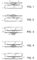
- la figure 1 représente de manière simplifiée une première variante de réalisation d'un dispositif de déplacement de petits volumes de liquide selon la présente invention,
- la figure 2 représente de manière simplifiée une deuxième variante de réalisation d'un dispositif de déplacement de petits volumes de liquide selon la présente invention,
- la figure 3 représente de manière simplifiée le dispositif de la deuxième variante de réalisation, dans une utilisation particulière,
- les figures 4
et 5 illustrent un mode de fonctionnement du dispositif de la figure 3, - la figure 6 représente de manière simplifiée une troisième variante de réalisation d'un dispositif de déplacement de petits volumes de liquide selon la présente invention,
- la figure 7 représente un dispositif de déplacement de petits volumes de liquide, à plusieurs micro-caténaires, selon la présente invention,
- la figure 8 représente un dispositif de déplacement de petits volumes de liquide comportant deux séries de micro-caténaires croisées, selon la présente invention,
- la figure 9 représente un dispositif de déplacement de petits volumes de liquide à micro-caténaire contrôlé en température,
- la figure 10 est une vue de dessus d'un dispositif de déplacement de petits volumes de liquide selon l'invention, en cours de fabrication,
- les figures 11A à 11F sont des vues correspondant à la coupe XX de la figure 10 et illustrent le procédé de fabrication du dispositif correspondant à la figure 10,
- les figures 12A et 12B sont des vues en coupe, respectivement longitudinale et transversale, d'un autre dispositif de déplacement de petits volumes de liquide selon l'invention,
- les figures 13A à 13D illustrent le procédé de fabrication d'un autre dispositif de déplacement de petits volumes de liquide selon l'invention,
- les figures 14A à 14E illustrent le procédé de fabrication d'encore un autre dispositif de déplacement de petits volumes de liquide selon l'invention,
- la figure 15 est une vue de dessus d'un dispositif de déplacement de petits volumes de liquide, mettant en oeuvre des aiguillages, selon l'invention,
- la figure 16 est une vue de dessus d'un dispositif de déplacement de petits volumes de liquide, présentant des emplacements préférentiels pour les petits volumes de liquide, selon l'invention.
- FIG. 1 is a simplified representation of a first variant embodiment of a device for moving small volumes of liquid according to the present invention,
- FIG. 2 is a simplified representation of a second variant embodiment of a device for moving small volumes of liquid according to the present invention;
- FIG. 3 is a simplified representation of the device of the second variant embodiment, for a particular use,
- FIGS. 4 and 5 illustrate a mode of operation of the device of FIG. 3,
- FIG. 6 schematically represents a third variant embodiment of a device for moving small volumes of liquid according to the present invention,
- FIG. 7 represents a device for moving small volumes of liquid, with several micro-catenaries, according to the present invention,
- FIG. 8 represents a device for displacing small volumes of liquid comprising two series of crossed micropatenaries, according to the present invention,
- FIG. 9 represents a device for moving small volumes of temperature-controlled microcatalytic liquid,
- FIG. 10 is a view from above of a device for moving small volumes of liquid according to the invention, during manufacture,
- FIGS. 11A to 11F are views corresponding to section XX of FIG. 10 and illustrate the manufacturing method of the device corresponding to FIG. 10,
- FIGS. 12A and 12B are cross-sectional views, respectively longitudinal and transverse, of another device for moving small volumes of liquid according to the invention,
- FIGS. 13A to 13D illustrate the method of manufacturing another device for moving small volumes of liquid according to the invention,
- FIGS. 14A to 14E illustrate the method of manufacturing yet another device for moving small volumes of liquid according to the invention,
- FIG. 15 is a view from above of a device for moving small volumes of liquid, using switches, according to the invention,
- Figure 16 is a top view of a device for moving small volumes of liquid, having preferred locations for small volumes of liquid, according to the invention.
Une première variante de l'invention est représentée à la figure 1. Le dispositif représenté, qui peut être appelé puce, comprend un substrat plan 1, de préférence en matériau isolant. L'une des faces du substrat 1 comporte des électrodes 2 alignées selon la direction prévue pour le déplacement des micro-gouttes. Un fil conducteur 3 ou micro-caténaire est disposé sensiblement parallèlement au substrat 1 et à une distance déterminée par rapport à ce substrat. Le micro-caténaire 3 est situé en vis-à-vis des électrodes 2. L'ensemble baigne dans un milieu ambiant 4 qui peut être un gaz ou un liquide non miscible avec le liquide de la micro-goutte 5.A first variant of the invention is shown in FIG. 1. The device shown, which may be called a chip, comprises a
Le dispositif selon l'invention permet de déformer ou de déplacer la goutte 5 par l'application d'un champ électrique entre le micro-caténaire et au moins l'une des électrodes 2. Le déplacement de la goutte peut s'expliquer en faisant référence à l'art antérieur cité plus haut et qui concerne les forces électrostatiques.The device according to the invention can deform or move the
Le micro-caténaire 3 assurant une fonction de guidage pour la goutte pendant son déplacement, il est préférable qu'il soit mouillant pour le liquide formant la goutte.The micro-catenary 3 providing a guiding function for the drop during its movement, it is preferable that it is wetting for the liquid forming the drop.
Si le liquide formant la goutte est électriquement conducteur, il est préférable de recouvrir les électrodes 2 d'une couche isolante et/ou d'enrober le micro-caténaire par une fine couche isolante.If the liquid forming the drop is electrically conductive, it is preferable to cover the
La tension électrique appliquée entre le micro-caténaire et les électrodes, permettant la déformation ou le déplacement de la goutte, peut être continue ou alternative.The voltage applied between the micro-catenary and the electrodes, allowing the deformation or displacement of the drop, can be continuous or alternative.
La figure 1 fait référence à une seule goutte, cependant il est tout à fait possible d'envisager le déplacement de plusieurs gouttes sur le même micro-caténaire.Figure 1 refers to a single drop, however it is quite possible to consider the displacement of several drops on the same micro-catenary.
La configuration du dispositif selon l'invention présente de nombreux avantages. Le micro-caténaire présente deux fonctions : une fonction électrique et une fonction de guidage de la goutte. Technologiquement, il est très simple à mettre en oeuvre. Il n'est pas nécessaire de confiner la goutte entre deux plans. Le micro-caténaire peut être très fin, ce qui limite la surface liquide/solide et donc minimise les interactions chimiques, biologique ou physico-chimique (mouillage). Le fait de mettre en contact la goutte avec le micro-caténaire permet de se placer dans une configuration électrique favorable aux différents principes permettant le déplacement de la goutte. Un autre avantage est d'avoir un composant permettant de travailler avec plusieurs modes d'utilisations qui vont être décrits dans la suite de la description.The configuration of the device according to the invention has many advantages. The micro-catenary has two functions: an electrical function and a guide function of the drop. Technologically, it is very simple to put in artwork. It is not necessary to confine the drop between two planes. The micro-catenary can be very thin, which limits the liquid / solid surface and thus minimizes the chemical, biological or physicochemical (wetting) interactions. The fact of bringing the drop into contact with the micro-catenary makes it possible to place oneself in an electrical configuration that is favorable to the various principles allowing the displacement of the drop. Another advantage is to have a component to work with several modes of use that will be described in the following description.
Dans la première variante de l'invention, représentée à la figure 1, la goutte est toujours en contact avec la surface du substrat portant les électrodes. Plusieurs électrodes 2 sont alignées suivant la direction du micro-caténaire 3. Le substrat est par exemple en verre mais on peut aussi utiliser tout type de matériau isolant comme la céramique ou le plastique, ou un substrat de silicium ayant une couche isolante. Cette couche isolante peut être de l'oxyde de silicium. Les électrodes 2 peuvent être réalisées par une couche d'or ou d'aluminium ou par tout autre matériau conducteur. Les électrodes peuvent avoir une dimension de quelques dizaines de µm2 jusqu'à 1 mm2 suivant les dimensions des gouttes à transporter. La structuration des électrodes peut être obtenue par les méthodes classiques des micro-technologie, c'est-à-dire par photolithographie.In the first variant of the invention, shown in Figure 1, the drop is always in contact with the surface of the substrate carrying the electrodes.
Le micro-caténaire peut être un fil d'or, d'aluminium, de platine ou d'un autre matériau conducteur. Le fil peut avoir un diamètre d'une dizaine de µm ou d'une centaine de µm. L'espacement entre le fil conducteur et le substrat peut être d'une dizaine de µm à plusieurs centaines de µm. Typiquement, on peut utiliser un fil d'or de 25 µm de diamètre espacé d'une centaine de µm du plan des électrodes.The micro-catenary can be a gold wire, aluminum, platinum or other conductive material. The wire may have a diameter of about ten microns or a hundred microns. The spacing between the conductive wire and the substrate may be from ten microns to several hundred microns. Typically, it is possible to use a
Le micro-caténaire est connecté à un potentiel de référence Vo. On applique un potentiel V à l'une des électrodes 2, les autres étant au potentiel de référence Vo.The micro-catenary is connected to a reference potential Vo. A potential V is applied to one of the
Il a été vérifié que la goutte tend à se placer sur l'électrode où est appliqué le potentiel V. Ceci a été observé dans le cas d'un liquide isolant tel que l'huile, ainsi qu'avec un liquide non isolant tel que l'eau salée. Dans ce dernier cas, les électrodes 2 ont été préalablement recouvertes d'une fine couche isolante de parylène d'une épaisseur de l'ordre du µm ou d'un matériau isolant tel que l'oxyde de silicium (SiO2) , du nitrure de silicium (Si3N4) ou du Téflon®.It has been verified that the drop tends to be placed on the electrode where the potential V is applied. This has been observed in the case of an insulating liquid such as oil, as well as with a non-insulating liquid such as salted water. In the latter case, the
En activant successivement les différentes électrodes on peut déplacer la goutte. Le déplacement peut s'expliquer en faisant référence à l'art antérieur. Les tensions d'activations sont de quelques centaines de volts. Moins la surface du substrat portant les électrodes est mouillante, plus la tension d'activation peut être diminuée. De même, plus les électrodes sont rapprochées, plus la tension d'activation peut être diminuée. L'espacement entre électrodes est par exemple de quelques µm.By successively activating the different electrodes, the drop can be moved. The displacement can be explained by referring to the prior art. Activation voltages are a few hundred volts. The less wetting the surface of the substrate carrying the electrodes, the lower the activation voltage can be. Likewise, the closer the electrodes are, the lower the activation voltage can be. The spacing between electrodes is for example a few microns.
Une deuxième variante de l'invention est représentée à la figure 2. Du point de vue de la réalisation technologique cette variante est identique à la précédente. Cependant, ici la goutte 15 est accrochée au micro-caténaire 13 sans être en contact avec les électrodes 12 présentes sur le substrat 11. Il est préférable que la surface du micro-caténaire 13 soit rendue mouillante pour le liquide formant la goutte afin d'assurer un bon accrochage. De même, les électrodes 12 peuvent être recouvertes d'une couche isolante. Il est aussi préférable d'avoir un diamètre de caténaire d'une centaine de µm pour que les forces de capillarités soient suffisamment grandes devant les forces de pesanteur. Ainsi, des gouttes de dimensions raisonnables peuvent être accrochées au micro-caténaire. Par exemple, une goutte de plusieurs microlitres d'huile peut être accrochée à un caténaire de 300 µm de largeur.A second variant of the invention is represented in Figure 2. From the point of view of the technological realization this variant is identical to the previous one. However, here the
Il a été vérifié que l'application d'une tension électrique entre le micro-caténaire 13 et l'une des électrodes 12 placée à proximité de la goutte 15 entraîne une déformation de la goutte. Cette déformation tend à attirer la goutte vers l'électrode activée.It has been verified that the application of a voltage between the micro-catenary 13 and one of the
De cette manière, en disposant plusieurs électrodes 12 sur le substrat 11 et en alignant les électrodes suivant la direction du micro-caténaire 13, on a constaté qu'il était possible de déplacer une goutte en appliquant successivement une tension électrique entre les différentes électrodes et le micro-caténaire. Ainsi, dans ce cas, la goutte se déplace en étant supportée par le micro-caténaire sans jamais être en contact avec le substrat ou les électrodes. Dans ce cas précis, il n'y a donc pas de contrainte sur les propriétés de mouillage de la surface du substrat.In this way, by disposing a plurality of
On trouvera une description de la forme onduloïdale d'une goutte mouillante sur une fibre dans l'article "Gouttes, bulles, perles et ondes" de P. G. de Gennes et al., Éditions Belin, 2002, page 19. On a aussi constaté que suivant les dimensions de la goutte, la forme pouvait être différente quand la pesanteur n'est plus négligeable. La goutte a tendance à pendre en dessous du caténaire. Dans le cas de la figure 2, les forces électrostatiques s'ajoutent à la pesanteur. Il est ainsi préférable de renverser le système pour que les forces électrostatiques s'opposent à la pesanteur afin d'éviter les risques de décrochage de la goutte du micro-caténaire. C'est ce que montre la figure 3.A description of the wavy shape of a wetting drop on a fiber can be found in the article "Drops, bubbles, beads and waves" by PG de Gennes et al., Belin Publishing, 2002, page 19. It has also been found that according to the dimensions of the drop, the shape could be different when gravity is no longer negligible. The drop tends to hang below the catenary. In the case of Figure 2, the electrostatic forces add to gravity. It is thus preferable to reverse the system so that the electrostatic forces are opposed to gravity to avoid the risk of stalling the drop of the micro-catenary. This is shown in Figure 3.
Si on augmente la tension d'activation, la goutte peut se déformer jusqu'à toucher l'électrode d'activation, C'est ce que montre la figure 4.If the activation voltage is increased, the drop may deform until it reaches the activation electrode. This is shown in FIG.
Une diminution ou une annulation de la tension d'activation peut entraîner alors les deux scénarios suivants :
si l'électrode 12 est mouillante (voir la figure 5), la goutte 15 restera naturellement accrochée à la surface par les forces de capillarité, le processus est alors irréversible ;- si la surface de l'électrode 12 est très hydrophobe, la goutte démouillera de la surface pour revenir à la position illustrée par la figure 3 et dans ce cas le processus est réversible, c'est-à-dire que l'on peut à volonté imposer le contact entre la goutte et l'électrode d'activation en jouant sur la tension d'activation.
- if the
electrode 12 is wetting (see Figure 5), thedrop 15 will naturally remain attached to the surface by the capillary forces, the process is then irreversible; - if the surface of the
electrode 12 is very hydrophobic, the drop will dewake from the surface to return to the position illustrated in FIG. in this case the process is reversible, that is to say that it is possible to impose the contact between the drop and the activation electrode by varying the activation voltage.
Ainsi suivant les dimensions et les propriétés de mouillage, on peut soit transférer la goutte du micro-caténaire vers le substrat soit imposer momentanément le mouillage de la goutte sur la surface du substrat.Thus, depending on the dimensions and the wetting properties, it is possible to transfer the drop of the micro-catenary to the substrate or to momentarily impose the wetting of the drop on the surface of the substrate.
En conclusion, avec le dispositif selon l'invention, il est possible de déplacer une goutte le long d'un micro-caténaire avec les deux possibilités suivantes :
- la goutte glisse en restant toujours en contact à la surface du substrat,
- la goutte se déplace sans qu'il y ait contact avec la surface du substrat. Dans ce dernier cas, on peut, par exemple après un déplacement sans contact sur une certaine longueur de caténaire, imposer temporairement l'étalement de la goutte sur la surface du substrat ou transférer la goutte du micro-caténaire vers la surface du substrat.
- the drop slides while always remaining in contact with the surface of the substrate,
- the drop moves without contact with the surface of the substrate. In the latter case, one can, for example after a displacement without contact over a certain length of catenary, temporarily impose the spreading of the drop on the surface of the substrate or transfer the drop of the micro-catenary to the surface of the substrate.
Une troisième variante de l'invention est représentée à la partie A de la figure 6. Le substrat 21 est réalisé dans un matériau conducteur ou est recouvert d'une couche conductrice 22. Il est préférable aussi de déposer une couche isolante non représentée sur la figure 6) à la surface du substrat (ou de la couche conductrice) en contact avec la goutte. De plus, cette surface présente une rugosité asymétrique (par exemple en toit d'usine) comme le montre la partie B de la figure 6).A third variant of the invention is shown in part A of FIG. 6. The
La surface du substrat (ou de la couche conductrice) en contact avec la goutte est avantageusement rendue non mouillante vis-à-vis de la goutte 25. La goutte 25 est accrochée au micro-caténaire 23 et, de plus, repose sur la surface du substrat ou de la couche conductrice. L'application d'une tension alternative entre le micro-caténaire et la couche conductrice 22 permet de faire vibrer la goutte 25. Il a été vérifié qu'il est possible de déplacer la goutte 25 le long du micro-caténaire 23. Ceci peut s'expliquer en faisant référence à l'article "Moving droplets on asymmetrically structured surfaces" cité plus haut.The surface of the substrate (or of the conductive layer) in contact with the droplet is advantageously rendered non-wetting with respect to the
Un autre aspect de l'invention est représenté par la figure 7. Le substrat 31 supporte une matrice d'électrodes 32, réparties en lignes et en colonnes, pouvant être recouvertes d'une couche isolante (non représentée). Plusieurs micro-caténaires 33 sont mis en parallèles suivant les lignes d'électrodes. Les micro-caténaires 33 sont positionnées à une distance donnée de la surface du substrat grâce à des espaceurs 36. De cette manière, il est possible de travailler en parallèle sur plusieurs lignes d'électrodes, et de déplacer plusieurs gouttes par une des méthodes précédemment décrites.Another aspect of the invention is shown in FIG. 7. The
Un autre aspect de l'invention est représenté par la figure 8. Le substrat 41 supporte une matrice d'électrodes 42, réparties en lignes et en colonnes, pouvant être recouvertes d'une fine couche isolante (non représentée). Une première série de micro-caténaires 43 est mise en parallèle suivant les lignes d'électrodes. Les micro-caténaires 43 sont positionnées à une distance donnée de la surface du substrat grâce à des espaceurs 46. Une deuxième série de micro-caténaires 47 est mise en parallèle mais placée perpendiculairement à la série de micro-caténaires 43, c'est-à-dire suivant la direction des colonnes d'électrodes. Les micro-caténaires 47 sont positionnés à une distance donnée de la surface du substrat grâce à des espaceurs 48. Les espaceurs 46 et 48 peuvent être de hauteurs différentes. Ainsi il est possible de déplacer des gouttes suivant deux directions perpendiculaires.Another aspect of the invention is shown in FIG. 8. The
Un autre aspect de l'invention consiste à utiliser le micro-caténaire pour chauffer une goutte de liquide. Ceci peut être obtenu très facilement par effet Joule, en faisant circuler un courant électrique le long du micro-caténaire. Ceci est schématisé par la figure 9. Sur cette figure, on a représenté un substrat isolant 51 supportant des électrodes 52 alignées en vis-à-vis d'un micro-caténaire 53 supporté par des espaceurs 56. La goutte peut être amenée à une position quelconque du micro-caténaire 53 grâce à l'un des procédés décrits précédemment. De préférence, on placera la goutte au milieu du micro-caténaire. En effet, en raison de la symétrie du système, le profil de température T du micro-caténaire présente une forme de cloche schématisée par la courbe 59. Il est bien connu que la résistivité du matériau électrique dépend en générale de la température. Ainsi, on peut aisément contrôler la température du système simplement en mesurant la résistance du micro-caténaire.Another aspect of the invention is to use the micro-catenary to heat a drop of liquid. This can be obtained very easily by Joule effect, by circulating an electric current along the micro-catenary. This is shown schematically in FIG. 9. In this figure, there is shown an insulating
L'avantage est alors d'avoir un système caténaire-goutte ayant une masse thermique très faible, ce qui n'est pas le cas de l'art antérieur où les réactions s'effectuent dans des liquides placés en contact avec des puits ou des canaux. Ainsi, il est facile de chauffer ou de laisser refroidir la goutte avec des temps très courts. Ceci est particulièrement bien adapté à certains protocoles biologiques nécessitant un cyclage en température, comme la PCR (voir l'article "Miniaturized flow-through PCR with différent template types in a silicon chip thermocycler" cité ci-dessus.The advantage is then to have a catenary-drop system having a very low thermal mass, which is not the case of the prior art where the reactions are carried out in liquids placed in contact with wells or wells. canals. Thus, it is easy to heat or cool the drop with very short times. This is particularly well suited to certain biological protocols requiring temperature cycling, such as PCR (see the article "Miniaturized flow-through PCR with different template types in a silicon chip thermocycler" cited above.
On va maintenant décrire des modes de réalisation de dispositifs selon l'invention.Embodiments of devices according to the invention will now be described.
La figure 10 est une vue de dessus d'un dispositif selon un premier mode de réalisation, en cours de fabrication. Les figures 11A à 11F illustrent les étapes du procédé de fabrication selon ce premier mode.Figure 10 is a top view of a device according to a first embodiment, during manufacture. Figures 11A to 11F illustrate the steps of the manufacturing method according to this first mode.
Le dispositif comporte un substrat 61 en verre, en silice, en plastique ou en silicium recouvert d'une couche isolante. Sur ce substrat est déposée une couche conductrice 60, par exemple en or, en aluminium, ou en ITO (voir la figure 11A) . Cette couche conductrice 60 est structurée par une étape de photolithographie afin de définir une matrice d'électrodes 62 connectées à des plots 64 par des lignes 65 (voir les figures 10 et 11 B) . La dimension des électrodes est de quelques dizaines à quelques centaines de µm (typiquement 500 µm par 500 µm). L'espacement entre chaque électrode est de quelques µm (5 à 10 µm) . La structuration de la couche conductrice conduit aussi à l'obtention de plots 67 disposés de part et d'autre des lignes d'électrodes 62). Le substrat est ensuite recouvert d'une couche 68 d'un matériau isolant tel que de l'oxyde de silicium ou du Si3N4, d'épaisseur de l'ordre du 0,1 à 1 µm (voir la figure 11C). Une étape de gravure de la couche isolante localisée sur les plots 64 et 67 permettra la reprise de contact électrique (voir la figure 11D).The device comprises a
On dépose alors une résine épaisse (par exemple la résine EPON SU8 Epoxy Resin, cf. le brevet américain 4 882 245) que l'on structure par photolithographie pour réaliser les espaceurs 66. L'épaisseur de la couche formant l'espaceur est de quelques dizaines à quelques centaines de µm (voir la figure 11E).A thick resin is then deposited (for example EPON resin SU8 Epoxy Resin, see US Pat. No. 4,882,245) which is photolithographically structured to form
Le substrat est découpé afin d'obtenir des puces individualisées (une seule puce étant montrée sur les figures 10 et 11A à 11E par souci de simplification). Par les procédés microtechnologiques, on peut ainsi réaliser sur une galette de diamètre 100 mm un grand nombre de composants. Chaque puce est collée à un support 69 comme il est coutume de faire en microélectronique (voir la figure 11F). Il reste à réaliser des ponts électriques 70 entre les plots 64 ou 67 et des plots de connexion du support 69 grâce à l'utilisation d'une machine de soudure électrique couramment utilisée en microélectronique. Avec cette même machine, on peut aussi réaliser les micro-caténaires 63 entre deux plots 67 opposés d'une même ligne d'électrodes 62. Les fils de connexion utilisés dans les machines de soudure sont par exemple des fils d'or ou d'aluminium d'un diamètre de quelques dizaines de µm (par exemple 25 µm). Suivant l'application, on choisira tel ou tel matériau pour réaliser le micro-caténaire, par exemple l'or et l'aluminium ont des propriétés de mouillage différentes.The substrate is cut in order to obtain individualized chips (a single chip being shown in Figures 10 and 11A to 11E for the sake of simplification). By microtechnological processes, it is thus possible to make a large number of components on a wafer with a diameter of 100 mm. Each chip is glued to a support 69 as is customary in microelectronics (see Figure 11F). It remains to realize
Une variante de réalisation est représentée aux figures 12A et 12B, la figure 12B étant une vue en coupe selon l'axe YY de la figure 12A. L'espaceur est réalisé par micro-usinage d'un substrat 76 assemblé au substrat 61 équipé comme le montre la figure 11D. Le substrat 76 comporte un système de rainurage 77 permettant d'auto-aligner et d'auto-positionner le micro-caténaire 73 avec une grande précision. Le rainurage peut être réalisé par exemple en réalisant des gravures chimiques anisotropes dans un substrat en silicium monocristallin.An alternative embodiment is shown in Figures 12A and 12B, Figure 12B being a sectional view along the axis YY of Figure 12A. The spacer is made by micromachining a
Pour confiner le composant réalisé, par exemple pour limiter l'évaporation, on recouvre éventuellement le composant par un film 74. Un simple film autocollant peut être utilisé.To confine the component made, for example to limit evaporation, the component is optionally covered with a
L'injection des gouttes 75 peut s'effectuer de différentes manières. On peut utiliser un système de dispense de goutte (tête d'imprimante). On peut aussi percer le film autocollant 74 par une aiguille et injecter les gouttes avec cette aiguille. Le film autocollant joue alors le rôle de septum. Une autre solution consiste à utiliser à nouveau le système de rainurage pour positionner des micro-capillaires 72. Ainsi, les extrémités des micro-capillaires 72 sont naturellement placés à proximité des micro-caténaires 73 correspondants et auto-alignés avec eux. On peut alors par exemple contrôler l'injection des liquides par un pousse-seringue connecté à l'autre extrémité des micro-capillaires ou en utilisant un système pressurisé.The injection of the
Un deuxième mode de réalisation est illustré par les figures 13A à 13D d'une part et 14A à 14E d'autre part. Dans ce mode de réalisation, le micro-caténaire est directement micro-usiné dans un deuxième substrat.A second embodiment is illustrated in Figures 13A to 13D on the one hand and 14A to 14E on the other hand. In this embodiment, the micro-catenary is directly micro-machined in a second substrate.
Les figures 13A à 13C sont des vues de côté et en coupe. La figure 13D est une vue de dessus correspondant à la figure 13B.Figures 13A to 13C are side views and sectional views. Figure 13D is a top view corresponding to Figure 13B.
La figure 13A montre un support 80 constituant le deuxième substrat. Une couche conductrice 81 est déposée sur une face du deuxième substrat 80. Par une étape de photo-lithogravure, on définit la forme du micro-caténaire et de ses plots de connexion. La figure 13D montre la forme donnée au micro-caténaire 83 et à ses plots de connexion 82.Figure 13A shows a
Le deuxième substrat 80 est ensuite gravé pour définir une ouverture 84 libérant le micro-caténaire 83 (voir les figures 13B et 13D). La figure 14D est une vue de dessus selon le plan DD indiqué sur la figure 14C et sans la couche 96.The
Le deuxième substrat 80 ainsi usiné est solidarisé à une structure 85 du type de celle représentée à la figure 11C. La solidarisation est faite de façon que le micro-caténaire 83 soit disposé en vis-à-vis d'une rangée d'électrodes d'activation (voir la figure 13C). Les connexions électriques vers le micro-caténaire n'ont pas été représentées.The
Les figures 14A, 14B, 14C et 14E sont des vues de côté et en coupe. La figure 14D est une vue de dessus correspondant au plan DD de la figure 14C.Figs. 14A, 14B, 14C and 14E are side views and sectional views. Figure 14D is a top view corresponding to the plane DD of Figure 14C.
la figure 14A montre un support 90 constituant le deuxième substrat. Une couche isolante 95 et une couche conductrice 91 sont successivement déposées sur une face du deuxième substrat 90. Par une étape de photo-lithographie, on définit la forme du micro-caténaire et de ses plots de connexion. La figure 14D montre la forme donnée au micro-caténaire 93 et à ses plots de connexion 92.Figure 14A shows a
Une autre couche est déposée sur le deuxième substrat 90 en recouvrant le micro-caténaire. Par une autre étape de photo-lithographie, on définit la forme de cette autre couche et la forme de la couche 95 pour révéler les plots de connexion 92 et laisser subsister une bande étroite 96 sur le micro-caténaire 93 et une bande étroite sous le micro-caténaire 93 (voir la figure 14B).Another layer is deposited on the
Une opération de gravure est ensuite effectuée à partir de la face arrière du deuxième substrat 90 pour obtenir une ouverture 94 (voir les figures 14C et 14D). La figure 14D est une vue de dessus selon le plan DD indiqué sur la figure 14C et sans la couche 96.An etching operation is then performed from the rear face of the
Le deuxième substrat ainsi usiné est solidarisé à une structure 98 du type de celle représentée à la figure 11C. La solidarisation est faite de façon que le micro-caténaire 93 soit disposé en vis-à-vis d'une rangée d'électrodes d'activation (voir la figure 14E). Les connexions électriques vers le micro-caténaire n'ont pas été représentées.The second substrate thus machined is secured to a
Dans ce cas, le micro-caténaire est compris entre deux couches jouant le rôle de support mécanique. Les couches 95 et 96 peuvent être réalisées dans un matériau précontraint en tension afin de bien tendre et de rigidifier le micro-caténaire. Ceci peut être obtenu à partir d'un deuxième substrat 90 en silicium sur lequel on dépose des couches 95 et 96 en nitrure de silicium par un procédé PECVD permettant de contrôler le niveau de contrainte du matériau déposé. Ce mode de réalisation permet aussi d'enrober le micro-caténaire par un matériau isolant.In this case, the micro-catenary is between two layers acting as a mechanical support. The
L'utilisation des micro-technologies permet donc de structurer les micro-caténaires par un empilement de différentes couches. On peut aussi dessiner différentes formes de micro-caténaires.The use of micro-technologies thus makes it possible to structure the micro-catenaries by stacking different layers. We can also draw different forms of micro-catenaries.
Ainsi, la figure 15 est une vue de dessus d'un dispositif selon l'invention montrant un micro-caténaire 103 pourvu d'un premier aiguillage 108 et d'un deuxième aiguillage 109. Le premier aiguillage 108 est connecté à des plots de connexion 110, 111 et le deuxième aiguillage 109 est connecté à des plots de connexion 112, 113. On remarque que le micro-caténaire 103 et les aiguillages 108 et 109 sont disposés sur un support mécanique. Les aiguillages permettent de mélanger, de trier ou de fractionner des gouttes.Thus, FIG. 15 is a view from above of a device according to the invention showing a micro-catenary 103 provided with a
La figure 16 est une vue de dessus d'un dispositif selon l'invention montrant un micro-caténaire 123 relié à des plots de connexion 127. Le micro-caténaire 123 est disposé sur un support 122 présentant une forme ondulatoire permettant de favoriser le positionnement des gouttes sur le micro-caténaire par les forces de capillarité.FIG. 16 is a view from above of a device according to the invention showing a micro-catenary 123 is connected to
Claims (22)
- Device for displacement of at least a small volume of liquid (5, 15) under the effect of an electrical control, including a substrate (1, 11) provided with first electrically conducting means (2, 12), the device also comprising second electrically conducting means arranged facing the first electrically conducting means, the first electrically conducting means and the second electrically conducting means possibly being connected to electrical supply means to enable the application of electrostatic forces to the small liquid volume (5, 15), characterized in that the second electrically conducting means include at least one conducting wire (3, 13), which forms a micro-catenary, arranged parallel to the substrate and at a fixed distance from the substrate to enable displacement of the small volume of liquid along said conducting wire under the effect of the applied electrostatic forces.
- Device according to claim 1, characterized in that the first electrically conducting means comprise electrodes (2, 12) placed on a non-electrically conducting face of the substrate and parallel to the direction of the conducting wire.
- Device according to claim 1, characterized in that the conducting wire (13) is wetting for the small liquid volume.
- Device according to claim 1, characterized in that the first electrically conducting means (62) and / or the second electrically conducting means are covered with a layer of electrically insulating material (68).
- Device according to claim 1, characterized in that it includes an ambient medium (4) in which the small liquid volume (5) displaces, this ambient medium being composed of a gas or liquid that is not miscible with the small liquid volume.
- Device according to claim 5, characterized in that the liquid that is not miscible with the small liquid volume is an oil bath.
- Device according to claim 1, characterized in that the determined distance between the conducting wire (3) and the substrate (1) is such that the small volume of liquid (5) is in contact with the substrate in the absence of any applied electrostatic forces, the substrate providing a non-wetting contact with the small volume of liquid.
- Device according to claim 1, characterized in that the determined distance between the conducting wire (13) and the substrate (11), and the diameter of the conducting wire (13), are such that the small volume of liquid (15) is not in contact with the substrate, in the absence of any applied electrostatic forces.
- Device according to claim 1, characterized in that the determined distance between the conducting wire and the substrate, and the diameter of the conducting wire, are such that the small volume of liquid is not in contact with the substrate, in the absence of any applied electrostatic forces.
- Device according to claim 8, characterized in that since the conducting wire (13) is arranged below the substrate (11), the determined distance between the conducting wire and the substrate is such that a first value of applied electrostatic forces causes contact between the small liquid volume and the substrate.
- Device according to claim 10, characterized in that the substrate offers a wetting contact to the small liquid volume (15) so as to transfer the small liquid volume onto the substrate when the applied electrostatic forces are cancelled out or are sufficiently low.
- Device according to claim 10, characterized in that the substrate provides a hydrophobic contact to the small liquid volume so that the small liquid volume (15) is supported only by the conducting wire when the applied electrostatic forces are cancelled out or are sufficiently low.
- Device according to claim 1, characterized in that it comprises means (77) of self-aligning and self-positioning the conducting wire (73) with the means of supplying and / or removing the small volume of liquid (72).
- Device according to claim 13, characterized in that the means of supplying and / or removing the small volume of liquid comprise at least one micro-capillary (72).
- Device according to claim 1, characterized in that the substrate (21) provides a surface (22) with asymmetric roughness to the small volume of liquid, the distance between the conducting wire and the substrate being such that the small volume of liquid (25) is in contact with the substrate under the effect of the applied electrostatic forces, and the substrate, due to its surface with asymmetric roughness, facilitates the displacement of the small liquid volume.
- Device according to claim 15, characterized in that the surface with asymmetric roughness has a factory roof type profile.
- Device according to claim 15 or 16, characterized in that the surface provided by the substrate to the small liquid volume is non-wetting.
- Device according to any one of claims 1 to 17, characterized in that the first conducting means may comprise a matrix (32) of electrodes forming rows and columns, the second electrically conducting means comprising conducting wires (33), at each row of electrodes corresponding to a conducting wire.
- Device according to any one of claims 1 to 17, characterized in that the first conducting means may also comprise a matrix (42) of electrodes forming rows and columns, the second electrically conducting means comprising a first series of conducting wires (43) and a second series of conducting wires (47), with a conducting wire in the first series of conducting wires corresponding to each row of electrodes, and a conducting wire in the second series of conducting wires corresponding to each column of electrodes.
- Device according to any of the above claims, characterized in that it comprises means of heating the conducting wire(s) (53).
- Device according to claim 20, characterized in that the heating means are electrical means for circulating an electrical current in the conducting wire(s) (53).
- Device according to claim 21, characterized in that it comprises means of controlling the temperature of the conducting wire(s) starting from a measurement of the electrical resistance of the conducting wire(s) (53).
Applications Claiming Priority (2)
| Application Number | Priority Date | Filing Date | Title |
|---|---|---|---|
| FR0207477 | 2002-06-18 | ||
| FR0207477A FR2841063B1 (en) | 2002-06-18 | 2002-06-18 | DEVICE FOR DISPLACING SMALL VOLUMES OF LIQUID ALONG A MICRO-CATENARY BY ELECTROSTATIC FORCES |
Publications (2)
| Publication Number | Publication Date |
|---|---|
| EP1376846A1 EP1376846A1 (en) | 2004-01-02 |
| EP1376846B1 true EP1376846B1 (en) | 2006-08-16 |
Family
ID=29595335
Family Applications (1)
| Application Number | Title | Priority Date | Filing Date |
|---|---|---|---|
| EP03101771A Expired - Lifetime EP1376846B1 (en) | 2002-06-18 | 2003-06-17 | Device for the displacement of small volumes of liquid along a micro-catenary using electrostatic forces |
Country Status (8)
| Country | Link |
|---|---|
| US (1) | US7052244B2 (en) |
| EP (1) | EP1376846B1 (en) |
| JP (1) | JP4350979B2 (en) |
| AT (1) | ATE336824T1 (en) |
| AU (1) | AU2003204633B2 (en) |
| CA (1) | CA2432607A1 (en) |
| DE (1) | DE60307552T2 (en) |
| FR (1) | FR2841063B1 (en) |
Families Citing this family (188)
| Publication number | Priority date | Publication date | Assignee | Title |
|---|---|---|---|---|
| US6989234B2 (en) * | 2002-09-24 | 2006-01-24 | Duke University | Method and apparatus for non-contact electrostatic actuation of droplets |
| US7329545B2 (en) * | 2002-09-24 | 2008-02-12 | Duke University | Methods for sampling a liquid flow |
| US6911132B2 (en) | 2002-09-24 | 2005-06-28 | Duke University | Apparatus for manipulating droplets by electrowetting-based techniques |
| US7041481B2 (en) | 2003-03-14 | 2006-05-09 | The Regents Of The University Of California | Chemical amplification based on fluid partitioning |
| FR2866493B1 (en) * | 2004-02-16 | 2010-08-20 | Commissariat Energie Atomique | DEVICE FOR CONTROLLING THE DISPLACEMENT OF A DROP BETWEEN TWO OR MORE SOLID SUBSTRATES |
| US7048889B2 (en) * | 2004-03-23 | 2006-05-23 | Lucent Technologies Inc. | Dynamically controllable biological/chemical detectors having nanostructured surfaces |
| JP2007534985A (en) * | 2004-04-24 | 2007-11-29 | コーニンクレッカ フィリップス エレクトロニクス エヌ ヴィ | Liquid optical device, control method thereof, and electronic device |
| FR2871070B1 (en) * | 2004-06-02 | 2007-02-16 | Commissariat Energie Atomique | MICRODISPOSITIVE AND EMULSION SEPARATION PROCESS |
| FR2872575A1 (en) * | 2004-07-01 | 2006-01-06 | Commissariat Energie Atomique | METHOD AND DEVICE FOR ANALYZING SMALL VOLUMES OF LIQUID |
| FR2872574B1 (en) * | 2004-07-01 | 2006-11-17 | Commissariat Energie Atomique | SYNCHRONOUS FLUORESCENCE DETECTION SYSTEM IN DROP |
| FR2872438B1 (en) | 2004-07-01 | 2006-09-15 | Commissariat Energie Atomique | DEVICE FOR DISPLACING AND PROCESSING LIQUID VOLUMES |
| FR2872809B1 (en) * | 2004-07-09 | 2006-09-15 | Commissariat Energie Atomique | METHOD OF ADDRESSING ELECTRODES |
| ATE485888T1 (en) | 2004-08-26 | 2010-11-15 | Life Technologies Corp | ELECTROWETTING DEVICES AND ASSOCIATED METHODS |
| JP4185904B2 (en) * | 2004-10-27 | 2008-11-26 | 株式会社日立ハイテクノロジーズ | Liquid transfer substrate, analysis system, and analysis method |
| FR2879946B1 (en) | 2004-12-23 | 2007-02-09 | Commissariat Energie Atomique | DISPENSER DEVICE FOR DROPS |
| JP4427461B2 (en) * | 2005-01-21 | 2010-03-10 | 株式会社日立ハイテクノロジーズ | Chemical analysis apparatus and analysis device |
| DK1859330T3 (en) * | 2005-01-28 | 2012-10-15 | Univ Duke | DEVICES AND METHODS OF HANDLING SMALL DROPS ON A PRINTED CIRCUIT CARD |
| US7454988B2 (en) * | 2005-02-10 | 2008-11-25 | Applera Corporation | Method for fluid sampling using electrically controlled droplets |
| CN101287845B (en) | 2005-05-11 | 2012-07-18 | 先进液体逻辑公司 | Method and device for conducting biochemical or chemical reactions at multiple temperatures |
| US20060260919A1 (en) * | 2005-05-17 | 2006-11-23 | Marco Aimi | Methods and apparatus for filling a microswitch with liquid metal |
| JP4547304B2 (en) * | 2005-05-31 | 2010-09-22 | 株式会社日立ハイテクノロジーズ | Liquid transfer substrate and analysis system |
| FR2887030B1 (en) * | 2005-06-09 | 2008-06-13 | Commissariat Energie Atomique | PLANAR DEVICE WITH AUTOMATED WELL ADDRESSING BY DYNAMIC ELECTROMOUILLAGE |
| FR2887305B1 (en) | 2005-06-17 | 2011-05-27 | Commissariat Energie Atomique | DEVICE FOR PUMPING BY ELECTROWETTING AND APPLICATION TO MEASUREMENTS OF ELECTRIC ACTIVITY |
| FR2888912B1 (en) | 2005-07-25 | 2007-08-24 | Commissariat Energie Atomique | METHOD FOR CONTROLLING COMMUNICATION BETWEEN TWO ZONES BY ELECTROWRINKING, DEVICE COMPRISING ISOLABLE ZONES AND OTHERS AND METHOD FOR PRODUCING SUCH DEVICE |
| US8637317B2 (en) * | 2006-04-18 | 2014-01-28 | Advanced Liquid Logic, Inc. | Method of washing beads |
| US20140193807A1 (en) | 2006-04-18 | 2014-07-10 | Advanced Liquid Logic, Inc. | Bead manipulation techniques |
| US8613889B2 (en) * | 2006-04-13 | 2013-12-24 | Advanced Liquid Logic, Inc. | Droplet-based washing |
| US8492168B2 (en) * | 2006-04-18 | 2013-07-23 | Advanced Liquid Logic Inc. | Droplet-based affinity assays |
| US9476856B2 (en) | 2006-04-13 | 2016-10-25 | Advanced Liquid Logic, Inc. | Droplet-based affinity assays |
| US7439014B2 (en) * | 2006-04-18 | 2008-10-21 | Advanced Liquid Logic, Inc. | Droplet-based surface modification and washing |
| US8470606B2 (en) * | 2006-04-18 | 2013-06-25 | Duke University | Manipulation of beads in droplets and methods for splitting droplets |
| US7901947B2 (en) * | 2006-04-18 | 2011-03-08 | Advanced Liquid Logic, Inc. | Droplet-based particle sorting |
| US8809068B2 (en) | 2006-04-18 | 2014-08-19 | Advanced Liquid Logic, Inc. | Manipulation of beads in droplets and methods for manipulating droplets |
| US7763471B2 (en) * | 2006-04-18 | 2010-07-27 | Advanced Liquid Logic, Inc. | Method of electrowetting droplet operations for protein crystallization |
| US7815871B2 (en) * | 2006-04-18 | 2010-10-19 | Advanced Liquid Logic, Inc. | Droplet microactuator system |
| US8716015B2 (en) | 2006-04-18 | 2014-05-06 | Advanced Liquid Logic, Inc. | Manipulation of cells on a droplet actuator |
| WO2007123908A2 (en) * | 2006-04-18 | 2007-11-01 | Advanced Liquid Logic, Inc. | Droplet-based multiwell operations |
| US7816121B2 (en) * | 2006-04-18 | 2010-10-19 | Advanced Liquid Logic, Inc. | Droplet actuation system and method |
| US8637324B2 (en) | 2006-04-18 | 2014-01-28 | Advanced Liquid Logic, Inc. | Bead incubation and washing on a droplet actuator |
| WO2009140671A2 (en) * | 2008-05-16 | 2009-11-19 | Advanced Liquid Logic, Inc. | Droplet actuator devices and methods for manipulating beads |
| US8980198B2 (en) | 2006-04-18 | 2015-03-17 | Advanced Liquid Logic, Inc. | Filler fluids for droplet operations |
| US10078078B2 (en) | 2006-04-18 | 2018-09-18 | Advanced Liquid Logic, Inc. | Bead incubation and washing on a droplet actuator |
| US8389297B2 (en) * | 2006-04-18 | 2013-03-05 | Duke University | Droplet-based affinity assay device and system |
| US8658111B2 (en) | 2006-04-18 | 2014-02-25 | Advanced Liquid Logic, Inc. | Droplet actuators, modified fluids and methods |
| US7822510B2 (en) * | 2006-05-09 | 2010-10-26 | Advanced Liquid Logic, Inc. | Systems, methods, and products for graphically illustrating and controlling a droplet actuator |
| US7939021B2 (en) * | 2007-05-09 | 2011-05-10 | Advanced Liquid Logic, Inc. | Droplet actuator analyzer with cartridge |
| US8041463B2 (en) * | 2006-05-09 | 2011-10-18 | Advanced Liquid Logic, Inc. | Modular droplet actuator drive |
| WO2009111769A2 (en) | 2008-03-07 | 2009-09-11 | Advanced Liquid Logic, Inc. | Reagent and sample preparation and loading on a fluidic device |
| FR2906237B1 (en) | 2006-09-22 | 2008-12-19 | Commissariat Energie Atomique | DOUBLE-SIDED FLUID COMPONENTS |
| WO2008091848A2 (en) * | 2007-01-22 | 2008-07-31 | Advanced Liquid Logic, Inc. | Surface assisted fluid loading and droplet dispensing |
| ES2423930T3 (en) | 2007-02-09 | 2013-09-25 | Advanced Liquid Logic, Inc. | Droplet actuator devices and methods using magnetic beads |
| WO2008101194A2 (en) | 2007-02-15 | 2008-08-21 | Advanced Liquid Logic, Inc. | Capacitance detection in a droplet actuator |
| WO2011084703A2 (en) | 2009-12-21 | 2011-07-14 | Advanced Liquid Logic, Inc. | Enzyme assays on a droplet actuator |
| US8202686B2 (en) * | 2007-03-22 | 2012-06-19 | Advanced Liquid Logic, Inc. | Enzyme assays for a droplet actuator |
| EP2837692A1 (en) | 2007-03-22 | 2015-02-18 | Advanced Liquid Logic, Inc. | Enzymatic assays for a droplet actuator |
| CA2719549A1 (en) * | 2007-04-10 | 2008-10-16 | Advanced Liquid Logic, Inc. | Droplet dispensing device and methods |
| CN101679078B (en) * | 2007-05-24 | 2013-04-03 | 数字化生物系统 | Digital Microfluidics Based on Electrowetting |
| US8951732B2 (en) | 2007-06-22 | 2015-02-10 | Advanced Liquid Logic, Inc. | Droplet-based nucleic acid amplification in a temperature gradient |
| US20100120130A1 (en) * | 2007-08-08 | 2010-05-13 | Advanced Liquid Logic, Inc. | Droplet Actuator with Droplet Retention Structures |
| US8268246B2 (en) | 2007-08-09 | 2012-09-18 | Advanced Liquid Logic Inc | PCB droplet actuator fabrication |
| AU2008293652B2 (en) * | 2007-08-24 | 2013-02-21 | Advanced Liquid Logic, Inc. | Bead manipulations on a droplet actuator |
| WO2009032863A2 (en) | 2007-09-04 | 2009-03-12 | Advanced Liquid Logic, Inc. | Droplet actuator with improved top substrate |
| DE102007047415B3 (en) * | 2007-10-04 | 2009-04-02 | Dräger Medical AG & Co. KG | A liquid vaporizer |
| WO2009052095A1 (en) * | 2007-10-17 | 2009-04-23 | Advanced Liquid Logic, Inc. | Reagent storage and reconstitution for a droplet actuator |
| US20100236928A1 (en) * | 2007-10-17 | 2010-09-23 | Advanced Liquid Logic, Inc. | Multiplexed Detection Schemes for a Droplet Actuator |
| US20100236929A1 (en) * | 2007-10-18 | 2010-09-23 | Advanced Liquid Logic, Inc. | Droplet Actuators, Systems and Methods |
| WO2009076414A2 (en) * | 2007-12-10 | 2009-06-18 | Advanced Liquid Logic, Inc. | Droplet actuator configurations and methods |
| FR2925792B1 (en) * | 2007-12-21 | 2012-12-07 | Commissariat Energie Atomique | LIQUID ELECTRODE ENERGY RECOVERY DEVICE |
| AU2008345138B2 (en) * | 2007-12-23 | 2014-05-29 | Advanced Liquid Logic, Inc. | Droplet actuator configurations and methods of conducting droplet operations |
| FR2930457B1 (en) | 2008-04-24 | 2010-06-25 | Commissariat Energie Atomique | PROCESS FOR MANUFACTURING RECONFIGURABLE MICROCHANNELS |
| WO2009137415A2 (en) | 2008-05-03 | 2009-11-12 | Advanced Liquid Logic, Inc. | Reagent and sample preparation, loading, and storage |
| US20110097763A1 (en) * | 2008-05-13 | 2011-04-28 | Advanced Liquid Logic, Inc. | Thermal Cycling Method |
| US11786036B2 (en) | 2008-06-27 | 2023-10-17 | Ssw Advanced Technologies, Llc | Spill containing refrigerator shelf assembly |
| US8286561B2 (en) | 2008-06-27 | 2012-10-16 | Ssw Holding Company, Inc. | Spill containing refrigerator shelf assembly |
| FR2934361B1 (en) | 2008-07-22 | 2012-12-28 | Commissariat Energie Atomique | DEVICE FOR VARYING THE PRESSURE OF A PNEUMATIC FLUID BY DISPLACING LIQUID DROPS AND HEAT PUMP USING SUCH A DEVICE |
| EP4512526A3 (en) | 2008-09-23 | 2025-06-04 | Bio-Rad Laboratories, Inc. | Droplet-based assay system |
| US8633015B2 (en) * | 2008-09-23 | 2014-01-21 | Bio-Rad Laboratories, Inc. | Flow-based thermocycling system with thermoelectric cooler |
| US8663920B2 (en) | 2011-07-29 | 2014-03-04 | Bio-Rad Laboratories, Inc. | Library characterization by digital assay |
| US10512910B2 (en) | 2008-09-23 | 2019-12-24 | Bio-Rad Laboratories, Inc. | Droplet-based analysis method |
| US11130128B2 (en) | 2008-09-23 | 2021-09-28 | Bio-Rad Laboratories, Inc. | Detection method for a target nucleic acid |
| US9132394B2 (en) | 2008-09-23 | 2015-09-15 | Bio-Rad Laboratories, Inc. | System for detection of spaced droplets |
| US9399215B2 (en) | 2012-04-13 | 2016-07-26 | Bio-Rad Laboratories, Inc. | Sample holder with a well having a wicking promoter |
| US9764322B2 (en) | 2008-09-23 | 2017-09-19 | Bio-Rad Laboratories, Inc. | System for generating droplets with pressure monitoring |
| WO2011120020A1 (en) | 2010-03-25 | 2011-09-29 | Quantalife, Inc. | Droplet transport system for detection |
| US9492797B2 (en) | 2008-09-23 | 2016-11-15 | Bio-Rad Laboratories, Inc. | System for detection of spaced droplets |
| US8709762B2 (en) | 2010-03-02 | 2014-04-29 | Bio-Rad Laboratories, Inc. | System for hot-start amplification via a multiple emulsion |
| US12162008B2 (en) | 2008-09-23 | 2024-12-10 | Bio-Rad Laboratories, Inc. | Partition-based method of analysis |
| US12090480B2 (en) | 2008-09-23 | 2024-09-17 | Bio-Rad Laboratories, Inc. | Partition-based method of analysis |
| US8951939B2 (en) | 2011-07-12 | 2015-02-10 | Bio-Rad Laboratories, Inc. | Digital assays with multiplexed detection of two or more targets in the same optical channel |
| US9417190B2 (en) | 2008-09-23 | 2016-08-16 | Bio-Rad Laboratories, Inc. | Calibrations and controls for droplet-based assays |
| US9156010B2 (en) | 2008-09-23 | 2015-10-13 | Bio-Rad Laboratories, Inc. | Droplet-based assay system |
| FR2936351B1 (en) | 2008-09-25 | 2010-10-15 | Commissariat Energie Atomique | VARIABLE CAPACITY SYSTEM WITH FLEXIBLE DIELECTRIC. |
| FR2936654B1 (en) | 2008-09-26 | 2010-10-22 | Commissariat Energie Atomique | EMISSION-RECEPTION RADIO FREQUENCY ANTENNA HAVING AN AMENDABLE TRANSMITTING-RECEPTION PARAMETERS |
| AU2009302329B2 (en) | 2008-10-07 | 2015-10-29 | Ssw Advanced Technologies, Llc | Spill resistant surfaces having hydrophobic and oleophobic borders |
| US8877512B2 (en) * | 2009-01-23 | 2014-11-04 | Advanced Liquid Logic, Inc. | Bubble formation techniques using physical or chemical features to retain a gas bubble within a droplet actuator |
| US8926065B2 (en) | 2009-08-14 | 2015-01-06 | Advanced Liquid Logic, Inc. | Droplet actuator devices and methods |
| CA2767056C (en) | 2009-09-02 | 2018-12-04 | Bio-Rad Laboratories, Inc. | System for mixing fluids by coalescence of multiple emulsions |
| US8846414B2 (en) | 2009-09-29 | 2014-09-30 | Advanced Liquid Logic, Inc. | Detection of cardiac markers on a droplet actuator |
| ES2613885T3 (en) | 2009-11-04 | 2017-05-26 | Ssw Holding Company, Inc. | Cooking appliance surfaces that have a pattern of confinement of splashes and their manufacturing procedures |
| US9091649B2 (en) | 2009-11-06 | 2015-07-28 | Advanced Liquid Logic, Inc. | Integrated droplet actuator for gel; electrophoresis and molecular analysis |
| DK2539450T3 (en) | 2010-02-25 | 2016-05-30 | Advanced Liquid Logic Inc | PROCEDURE FOR PREPARING NUCLEIC ACID LIBRARIES |
| US8399198B2 (en) | 2010-03-02 | 2013-03-19 | Bio-Rad Laboratories, Inc. | Assays with droplets transformed into capsules |
| JP5858441B2 (en) | 2010-03-15 | 2016-02-10 | ロス テクノロジー コーポレーション.Ross Technology Corporation | Plunger and method for obtaining a hydrophobic surface |
| CA2767182C (en) | 2010-03-25 | 2020-03-24 | Bio-Rad Laboratories, Inc. | Droplet generation for droplet-based assays |
| JP2013524169A (en) | 2010-03-25 | 2013-06-17 | クァンタライフ・インコーポレーテッド | Detection system for assay by droplet |
| EP2553473A4 (en) | 2010-03-30 | 2016-08-10 | Advanced Liquid Logic Inc | Droplet operations platform |
| US10787701B2 (en) | 2010-04-05 | 2020-09-29 | Prognosys Biosciences, Inc. | Spatially encoded biological assays |
| WO2011127099A1 (en) | 2010-04-05 | 2011-10-13 | Prognosys Biosciences, Inc. | Spatially encoded biological assays |
| US20190300945A1 (en) | 2010-04-05 | 2019-10-03 | Prognosys Biosciences, Inc. | Spatially Encoded Biological Assays |
| US9011662B2 (en) | 2010-06-30 | 2015-04-21 | Advanced Liquid Logic, Inc. | Droplet actuator assemblies and methods of making same |
| EP3574990B1 (en) | 2010-11-01 | 2022-04-06 | Bio-Rad Laboratories, Inc. | System for forming emulsions |
| US20130293246A1 (en) | 2010-11-17 | 2013-11-07 | Advanced Liquid Logic Inc. | Capacitance Detection in a Droplet Actuator |
| US12097495B2 (en) | 2011-02-18 | 2024-09-24 | Bio-Rad Laboratories, Inc. | Methods and compositions for detecting genetic material |
| JP2014512417A (en) | 2011-02-21 | 2014-05-22 | ロス テクノロジー コーポレーション. | Superhydrophobic and oleophobic coatings containing low VOC binder systems |
| CN103534360A (en) | 2011-03-18 | 2014-01-22 | 伯乐生命医学产品有限公司 | Multiplexed digital assays with combinatorial use of signals |
| GB201106254D0 (en) | 2011-04-13 | 2011-05-25 | Frisen Jonas | Method and product |
| US8339711B2 (en) * | 2011-04-22 | 2012-12-25 | Sharp Kabushiki Kaisha | Active matrix device and method of driving the same |
| EP3395957B1 (en) | 2011-04-25 | 2020-08-12 | Bio-Rad Laboratories, Inc. | Methods and compositions for nucleic acid analysis |
| CN103562729A (en) | 2011-05-02 | 2014-02-05 | 先进流体逻辑公司 | Molecular diagnostics platform |
| EP2711079B1 (en) | 2011-05-09 | 2018-12-19 | Advanced Liquid Logic, Inc. | Microfluidic Feedback Using Impedance Detection |
| WO2012154794A2 (en) | 2011-05-10 | 2012-11-15 | Advanced Liquid Logic, Inc. | Enzyme concentration and assays |
| CA2840949A1 (en) | 2011-07-06 | 2013-01-10 | Advanced Liquid Logic Inc | Reagent storage on a droplet actuator |
| US8901043B2 (en) | 2011-07-06 | 2014-12-02 | Advanced Liquid Logic, Inc. | Systems for and methods of hybrid pyrosequencing |
| US9513253B2 (en) | 2011-07-11 | 2016-12-06 | Advanced Liquid Logic, Inc. | Droplet actuators and techniques for droplet-based enzymatic assays |
| WO2013016413A2 (en) | 2011-07-25 | 2013-01-31 | Advanced Liquid Logic Inc | Droplet actuator apparatus and system |
| DE102011085428A1 (en) | 2011-10-28 | 2013-05-02 | Schott Ag | shelf |
| FR2982176B1 (en) * | 2011-11-09 | 2014-01-10 | Commissariat Energie Atomique | DEVICE AND METHOD FOR HANDLING DROPS |
| US10731199B2 (en) | 2011-11-21 | 2020-08-04 | Advanced Liquid Logic, Inc. | Glucose-6-phosphate dehydrogenase assays |
| EP2791255B1 (en) | 2011-12-15 | 2017-11-01 | Ross Technology Corporation | Composition and coating for superhydrophobic performance |
| US9223317B2 (en) | 2012-06-14 | 2015-12-29 | Advanced Liquid Logic, Inc. | Droplet actuators that include molecular barrier coatings |
| EP2864430A4 (en) | 2012-06-25 | 2016-04-13 | Ross Technology Corp | ELASTOMERIC COATINGS HAVING HYDROPHOBIC AND / OR OLEOPHOBIC PROPERTIES |
| WO2014004908A1 (en) | 2012-06-27 | 2014-01-03 | Advanced Liquid Logic Inc. | Techniques and droplet actuator designs for reducing bubble formation |
| WO2014062551A1 (en) | 2012-10-15 | 2014-04-24 | Advanced Liquid Logic, Inc. | Digital microfluidics cartridge and system for operating a flow cell |
| EP4592400A3 (en) | 2012-10-17 | 2025-10-29 | 10x Genomics Sweden AB | Methods and product for optimising localised or spatial detection of gene expression in a tissue sample |
| CA2916662C (en) | 2013-06-25 | 2022-03-08 | Prognosys Biosciences, Inc. | Methods and systems for determining spatial patterns of biological targets in a sample |
| CN111957453B (en) | 2013-08-13 | 2022-08-19 | 先进流体逻辑公司 | Method for improving accuracy and precision of drop metering using an on-actuator reservoir as a fluid input |
| KR20160081896A (en) | 2013-08-30 | 2016-07-08 | 일루미나, 인코포레이티드 | Manipulation of droplets on hydrophilic or variegated-hydrophilic surfaces |
| CA3060708A1 (en) | 2014-04-29 | 2015-11-05 | Illumina, Inc | Multiplexed single cell gene expression analysis using template switch and tagmentation |
| US20150370707A1 (en) * | 2014-06-24 | 2015-12-24 | Qualcomm Incorporated | Disunited shared-information and private-information caches |
| CN106999850B (en) | 2014-10-09 | 2020-04-07 | 亿明达股份有限公司 | Method and apparatus for separating immiscible liquids to effectively isolate at least one liquid |
| CN107406890B (en) | 2015-02-10 | 2023-07-18 | 亿明达股份有限公司 | Methods and compositions for analyzing cellular components |
| US10576471B2 (en) | 2015-03-20 | 2020-03-03 | Illumina, Inc. | Fluidics cartridge for use in the vertical or substantially vertical position |
| EP3901282B1 (en) | 2015-04-10 | 2023-06-28 | Spatial Transcriptomics AB | Spatially distinguished, multiplex nucleic acid analysis of biological specimens |
| RU2724998C2 (en) | 2015-05-11 | 2020-06-29 | Иллюмина, Инк. | Platform for detecting and analyzing therapeutic agents |
| WO2017007757A1 (en) | 2015-07-06 | 2017-01-12 | Illumina, Inc. | Balanced ac modulation for driving droplet operations electrodes |
| DK3334839T3 (en) | 2015-08-14 | 2021-04-26 | Illumina Inc | SYSTEMS AND PROCEDURES USING MAGNETIC REACTIVE SENSORS FOR DETERMINING A GENETIC PROPERTY |
| EP4086357A1 (en) | 2015-08-28 | 2022-11-09 | Illumina, Inc. | Nucleic acid sequence analysis from single cells |
| HK1253910A1 (en) | 2015-09-02 | 2019-07-05 | 伊卢米纳剑桥有限公司 | Systems and methods of improving droplet operations in fluidic systems |
| US10450598B2 (en) | 2015-09-11 | 2019-10-22 | Illumina, Inc. | Systems and methods for obtaining a droplet having a designated concentration of a substance-of-interest |
| WO2017070363A1 (en) | 2015-10-22 | 2017-04-27 | Illumina, Inc. | Filler fluid for fluidic devices |
| WO2017095845A1 (en) | 2015-12-01 | 2017-06-08 | Illumina, Inc. | Liquid storage and delivery mechanisms and methods |
| US11203016B2 (en) * | 2015-12-01 | 2021-12-21 | Illumina, Inc. | Digital microfluidic system for single-cell isolation and characterization of analytes |
| EP3440220B1 (en) | 2016-04-07 | 2020-03-25 | Illumina, Inc. | Methods and systems for construction of normalized nucleic acid libraries |
| JP6919181B2 (en) * | 2016-11-29 | 2021-08-18 | 株式会社リコー | Droplet dispensing device, droplet dispensing method, and manufacturing method of adherend |
| KR101905139B1 (en) * | 2017-02-17 | 2018-10-05 | 한국과학기술원 | Method and apparatus for controlling actuation of liquid using electrowetting phenomenon |
| KR101926723B1 (en) * | 2017-07-03 | 2018-12-07 | 한국과학기술원 | Apparatus and method of active flow controlling using electrowetting |
| ES2937927T3 (en) | 2018-01-29 | 2023-04-03 | St Jude Childrens Res Hospital Inc | Method for nucleic acid amplification |
| MX2022001324A (en) | 2019-07-31 | 2022-05-19 | Bioskryb Genomics Inc | ANALYSIS OF INDIVIDUAL CELLS. |
| US12157124B2 (en) | 2019-11-06 | 2024-12-03 | 10X Genomics, Inc. | Imaging system hardware |
| EP4061530B1 (en) | 2019-11-20 | 2025-12-10 | Nuclera Ltd | Spatially variable hydrophobic layers for digital microfluidics |
| US12405264B2 (en) | 2020-01-17 | 2025-09-02 | 10X Genomics, Inc. | Electrophoretic system and method for analyte capture |
| WO2021146573A1 (en) | 2020-01-17 | 2021-07-22 | E Ink Corporation | Spatially variable dielectric layers for digital microfluidics |
| WO2021154627A1 (en) | 2020-01-27 | 2021-08-05 | E Ink Corporation | Method for degassing liquid droplets by electrowetting actuation at higher temperatures |
| US12110541B2 (en) | 2020-02-03 | 2024-10-08 | 10X Genomics, Inc. | Methods for preparing high-resolution spatial arrays |
| WO2021168131A1 (en) | 2020-02-18 | 2021-08-26 | Nuclear Nucleics Ltd. | Adaptive gate driving for high frequency ac driving of ewod arrays |
| TWI795730B (en) | 2020-02-19 | 2023-03-11 | 英商核酸有限公司 | Latched transistor driving for high frequency ac driving of ewod arrays |
| WO2021222061A1 (en) | 2020-04-27 | 2021-11-04 | Nuclera Nucleics Ltd. | Segmented top plate for variable driving and short protection for digital microfluidics |
| US12416603B2 (en) | 2020-05-19 | 2025-09-16 | 10X Genomics, Inc. | Electrophoresis cassettes and instrumentation |
| EP4414459B1 (en) | 2020-05-22 | 2025-09-03 | 10X Genomics, Inc. | Simultaneous spatio-temporal measurement of gene expression and cellular activity |
| US12031177B1 (en) | 2020-06-04 | 2024-07-09 | 10X Genomics, Inc. | Methods of enhancing spatial resolution of transcripts |
| WO2021252747A1 (en) | 2020-06-10 | 2021-12-16 | 1Ox Genomics, Inc. | Fluid delivery methods |
| US20230304066A1 (en) | 2020-09-04 | 2023-09-28 | Baebies, Inc. | Microfluidic based assay for unbound bilirubin |
| JP7716730B2 (en) | 2020-09-15 | 2025-08-01 | 国立大学法人 名古屋工業大学 | Liquid control device and its use |
| WO2022061150A2 (en) | 2020-09-18 | 2022-03-24 | 10X Geonomics, Inc. | Sample handling apparatus and image registration methods |
| WO2022074399A1 (en) | 2020-10-08 | 2022-04-14 | Nuclera Nucleics Ltd | Electrowetting system and method for reagent-specific driving ewod arrays in microfluidic systems |
| CN116635153A (en) | 2020-11-04 | 2023-08-22 | 核蛋白有限公司 | Dielectric layer for digital microfluidic devices |
| EP4421491A3 (en) | 2021-02-19 | 2024-11-27 | 10X Genomics, Inc. | Method of using a modular assay support device |
| JP7528850B2 (en) * | 2021-04-12 | 2024-08-06 | トヨタ自動車株式会社 | Actuator |
| US12458185B2 (en) * | 2021-05-05 | 2025-11-04 | Kohler Co. | Hydrophobic field |
| KR20240033223A (en) | 2021-06-02 | 2024-03-12 | 배비스 인코포레이티드 | MICRO-REGIONAL THERMAL CONTROL FOR DIGITAL MICROFLUIDICS |
| US12553805B2 (en) | 2021-08-02 | 2026-02-17 | 10X Genomics, Inc. | Methods of preserving a biological sample |
| USD1064308S1 (en) | 2021-09-17 | 2025-02-25 | 10X Genomics, Inc. | Sample handling device |
| FR3127810A1 (en) | 2021-10-01 | 2023-04-07 | Commissariat à l'Energie Atomique et aux Energies Alternatives | Drop sorting process |
| WO2023122033A1 (en) | 2021-12-20 | 2023-06-29 | 10X Genomics, Inc. | Self-test for pathology/histology slide imaging device |
| WO2024072614A1 (en) | 2022-09-27 | 2024-04-04 | Nautilus Subsidiary, Inc. | Polypeptide capture, in situ fragmentation and identification |
| US20250060333A1 (en) | 2023-08-16 | 2025-02-20 | E Ink Corporation | Devices, methods, and systems for visualizing electrowetting pathing using electrophoretic materials |
| FR3153756A1 (en) | 2023-10-06 | 2025-04-11 | Commissariat A L'energie Atomique Et Aux Energies Alternatives | Optical sample analysis system |
| CN119771522B (en) * | 2024-12-13 | 2025-10-28 | 广州大学 | Liquid drop transportation magnetic control film robot and preparation method and application thereof |
Family Cites Families (3)
| Publication number | Priority date | Publication date | Assignee | Title |
|---|---|---|---|---|
| FR2548431B1 (en) * | 1983-06-30 | 1985-10-25 | Thomson Csf | ELECTRICALLY CONTROLLED FLUID MOVEMENT DEVICE |
| US5181016A (en) * | 1991-01-15 | 1993-01-19 | The United States Of America As Represented By The United States Department Of Energy | Micro-valve pump light valve display |
| FR2794039B1 (en) * | 1999-05-27 | 2002-05-03 | Osmooze Sa | DEVICE FOR FORMING, MOVING AND DIFFUSING SMALL CALIBRATED QUANTITIES OF LIQUIDS |
-
2002
- 2002-06-18 FR FR0207477A patent/FR2841063B1/en not_active Expired - Fee Related
-
2003
- 2003-06-10 US US10/457,375 patent/US7052244B2/en not_active Expired - Lifetime
- 2003-06-11 AU AU2003204633A patent/AU2003204633B2/en not_active Ceased
- 2003-06-17 DE DE60307552T patent/DE60307552T2/en not_active Expired - Lifetime
- 2003-06-17 CA CA002432607A patent/CA2432607A1/en not_active Abandoned
- 2003-06-17 EP EP03101771A patent/EP1376846B1/en not_active Expired - Lifetime
- 2003-06-17 AT AT03101771T patent/ATE336824T1/en not_active IP Right Cessation
- 2003-06-18 JP JP2003173970A patent/JP4350979B2/en not_active Expired - Fee Related
Also Published As
| Publication number | Publication date |
|---|---|
| AU2003204633B2 (en) | 2008-07-17 |
| CA2432607A1 (en) | 2003-12-18 |
| US20040007377A1 (en) | 2004-01-15 |
| AU2003204633A1 (en) | 2004-01-15 |
| JP4350979B2 (en) | 2009-10-28 |
| FR2841063B1 (en) | 2004-09-17 |
| US7052244B2 (en) | 2006-05-30 |
| JP2004022165A (en) | 2004-01-22 |
| FR2841063A1 (en) | 2003-12-19 |
| DE60307552D1 (en) | 2006-09-28 |
| DE60307552T2 (en) | 2007-08-09 |
| EP1376846A1 (en) | 2004-01-02 |
| ATE336824T1 (en) | 2006-09-15 |
Similar Documents
| Publication | Publication Date | Title |
|---|---|---|
| EP1376846B1 (en) | Device for the displacement of small volumes of liquid along a micro-catenary using electrostatic forces | |
| US6949176B2 (en) | Microfluidic control using dielectric pumping | |
| US8940147B1 (en) | Microfluidic hubs, systems, and methods for interface fluidic modules | |
| FR2866493A1 (en) | DEVICE FOR CONTROLLING THE DISPLACEMENT OF A DROP BETWEEN TWO OR MORE SOLID SUBSTRATES | |
| US8342207B2 (en) | Making a liquid/liquid or gas system in microfluidics | |
| Haswell | Development and operating characteristics of micro flow injection based on electroosmotic flow | |
| Chiou et al. | Droplet manipulation with light on optoelectrowetting device | |
| US7211223B2 (en) | Device for injection and mixing of liquid droplets | |
| EP1289660B1 (en) | High-performance system for parallel and selective dispensing of micro-droplets | |
| Zhao et al. | Micro air bubble manipulation by electrowetting on dielectric (EWOD): transporting, splitting, merging and eliminating of bubbles | |
| Lee et al. | Electrowetting-induced droplet detachment from hydrophobic surfaces | |
| US8883014B2 (en) | Monolithically formed EWOD device and method of making the same | |
| WO2006134307A1 (en) | Electrowetting pumping device and use for measuring electrical activity | |
| EP1356303B1 (en) | Method and system for performing in continuous flow a biological, chemical or biochemical protocol | |
| EP2545371B1 (en) | Microfluidic channel device with array of drive electrodes | |
| FR2884437A1 (en) | Micro-fluid unit for transferring matter between two non-miscible phases uses natural electrical forces to move at least one microdrop | |
| US20110104025A1 (en) | Method for producing reconfigurable microchannels | |
| EP2453220A1 (en) | Method for controlled evaporation of a drop of liquid in a microfluidic device | |
| FR2831081A1 (en) | Biological micro-reactor suitable for high throughput screening, forms alternating mobile liquid reactors and liquid separators in parallel capillaries | |
| EP2678106A1 (en) | Microfluidic extraction device having a stabilized liquid/liquid interface | |
| Bian et al. | A novel crescent electrode for droplet splitting in digital microfluidic | |
| Berry et al. | New Methods to Transport Fluids in Micro-Sized Devices | |
| Zeng et al. | Droplet creator based on electrowetting-on-dielectric for lab on a chip | |
| Royal et al. | Integrated sample preparation and sensing: Microresonator optical sensors embedded in digital electrowetting microfluidics systems | |
| Pei et al. | On-chip blade for accurate splitting of droplets in light-actuated digital microfluidics |
Legal Events
| Date | Code | Title | Description |
|---|---|---|---|
| PUAI | Public reference made under article 153(3) epc to a published international application that has entered the european phase |
Free format text: ORIGINAL CODE: 0009012 |
|
| AK | Designated contracting states |
Kind code of ref document: A1 Designated state(s): AT BE BG CH CY CZ DE DK EE ES FI FR GB GR HU IE IT LI LU MC NL PT RO SE SI SK TR |
|
| AX | Request for extension of the european patent |
Extension state: AL LT LV MK |
|
| 17P | Request for examination filed |
Effective date: 20040630 |
|
| AKX | Designation fees paid |
Designated state(s): AT BE BG CH CY CZ DE DK EE ES FI FR GB GR HU IE IT LI LU MC NL PT RO SE SI SK TR |
|
| 17Q | First examination report despatched |
Effective date: 20041202 |
|
| GRAP | Despatch of communication of intention to grant a patent |
Free format text: ORIGINAL CODE: EPIDOSNIGR1 |
|
| GRAS | Grant fee paid |
Free format text: ORIGINAL CODE: EPIDOSNIGR3 |
|
| GRAA | (expected) grant |
Free format text: ORIGINAL CODE: 0009210 |
|
| AK | Designated contracting states |
Kind code of ref document: B1 Designated state(s): AT BE BG CH CY CZ DE DK EE ES FI FR GB GR HU IE IT LI LU MC NL PT RO SE SI SK TR |
|
| PG25 | Lapsed in a contracting state [announced via postgrant information from national office to epo] |
Ref country code: IT Free format text: LAPSE BECAUSE OF FAILURE TO SUBMIT A TRANSLATION OF THE DESCRIPTION OR TO PAY THE FEE WITHIN THE PRESCRIBED TIME-LIMIT;WARNING: LAPSES OF ITALIAN PATENTS WITH EFFECTIVE DATE BEFORE 2007 MAY HAVE OCCURRED AT ANY TIME BEFORE 2007. THE CORRECT EFFECTIVE DATE MAY BE DIFFERENT FROM THE ONE RECORDED. Effective date: 20060816 Ref country code: RO Free format text: LAPSE BECAUSE OF FAILURE TO SUBMIT A TRANSLATION OF THE DESCRIPTION OR TO PAY THE FEE WITHIN THE PRESCRIBED TIME-LIMIT Effective date: 20060816 Ref country code: FI Free format text: LAPSE BECAUSE OF FAILURE TO SUBMIT A TRANSLATION OF THE DESCRIPTION OR TO PAY THE FEE WITHIN THE PRESCRIBED TIME-LIMIT Effective date: 20060816 Ref country code: SK Free format text: LAPSE BECAUSE OF FAILURE TO SUBMIT A TRANSLATION OF THE DESCRIPTION OR TO PAY THE FEE WITHIN THE PRESCRIBED TIME-LIMIT Effective date: 20060816 Ref country code: SI Free format text: LAPSE BECAUSE OF FAILURE TO SUBMIT A TRANSLATION OF THE DESCRIPTION OR TO PAY THE FEE WITHIN THE PRESCRIBED TIME-LIMIT Effective date: 20060816 Ref country code: CZ Free format text: LAPSE BECAUSE OF FAILURE TO SUBMIT A TRANSLATION OF THE DESCRIPTION OR TO PAY THE FEE WITHIN THE PRESCRIBED TIME-LIMIT Effective date: 20060816 Ref country code: AT Free format text: LAPSE BECAUSE OF FAILURE TO SUBMIT A TRANSLATION OF THE DESCRIPTION OR TO PAY THE FEE WITHIN THE PRESCRIBED TIME-LIMIT Effective date: 20060816 Ref country code: NL Free format text: LAPSE BECAUSE OF FAILURE TO SUBMIT A TRANSLATION OF THE DESCRIPTION OR TO PAY THE FEE WITHIN THE PRESCRIBED TIME-LIMIT Effective date: 20060816 Ref country code: IE Free format text: LAPSE BECAUSE OF FAILURE TO SUBMIT A TRANSLATION OF THE DESCRIPTION OR TO PAY THE FEE WITHIN THE PRESCRIBED TIME-LIMIT Effective date: 20060816 |
|
| REG | Reference to a national code |
Ref country code: GB Ref legal event code: FG4D Free format text: NOT ENGLISH |
|
| REG | Reference to a national code |
Ref country code: CH Ref legal event code: EP |
|
| REG | Reference to a national code |
Ref country code: IE Ref legal event code: FG4D Free format text: LANGUAGE OF EP DOCUMENT: FRENCH |
|
| REF | Corresponds to: |
Ref document number: 60307552 Country of ref document: DE Date of ref document: 20060928 Kind code of ref document: P |
|
| PG25 | Lapsed in a contracting state [announced via postgrant information from national office to epo] |
Ref country code: BG Free format text: LAPSE BECAUSE OF FAILURE TO SUBMIT A TRANSLATION OF THE DESCRIPTION OR TO PAY THE FEE WITHIN THE PRESCRIBED TIME-LIMIT Effective date: 20061116 Ref country code: DK Free format text: LAPSE BECAUSE OF FAILURE TO SUBMIT A TRANSLATION OF THE DESCRIPTION OR TO PAY THE FEE WITHIN THE PRESCRIBED TIME-LIMIT Effective date: 20061116 Ref country code: SE Free format text: LAPSE BECAUSE OF FAILURE TO SUBMIT A TRANSLATION OF THE DESCRIPTION OR TO PAY THE FEE WITHIN THE PRESCRIBED TIME-LIMIT Effective date: 20061116 |
|
| GBT | Gb: translation of ep patent filed (gb section 77(6)(a)/1977) |
Effective date: 20061101 |
|
| PG25 | Lapsed in a contracting state [announced via postgrant information from national office to epo] |
Ref country code: ES Free format text: LAPSE BECAUSE OF FAILURE TO SUBMIT A TRANSLATION OF THE DESCRIPTION OR TO PAY THE FEE WITHIN THE PRESCRIBED TIME-LIMIT Effective date: 20061127 |
|
| PG25 | Lapsed in a contracting state [announced via postgrant information from national office to epo] |
Ref country code: PT Free format text: LAPSE BECAUSE OF FAILURE TO SUBMIT A TRANSLATION OF THE DESCRIPTION OR TO PAY THE FEE WITHIN THE PRESCRIBED TIME-LIMIT Effective date: 20070116 |
|
| NLV1 | Nl: lapsed or annulled due to failure to fulfill the requirements of art. 29p and 29m of the patents act | ||
| REG | Reference to a national code |
Ref country code: IE Ref legal event code: FD4D |
|
| PLBE | No opposition filed within time limit |
Free format text: ORIGINAL CODE: 0009261 |
|
| STAA | Information on the status of an ep patent application or granted ep patent |
Free format text: STATUS: NO OPPOSITION FILED WITHIN TIME LIMIT |
|
| 26N | No opposition filed |
Effective date: 20070518 |
|
| BERE | Be: lapsed |
Owner name: COMMISSARIAT A L'ENERGIE ATOMIQUE Effective date: 20070630 |
|
| PG25 | Lapsed in a contracting state [announced via postgrant information from national office to epo] |
Ref country code: MC Free format text: LAPSE BECAUSE OF NON-PAYMENT OF DUE FEES Effective date: 20070630 |
|
| PG25 | Lapsed in a contracting state [announced via postgrant information from national office to epo] |
Ref country code: BE Free format text: LAPSE BECAUSE OF NON-PAYMENT OF DUE FEES Effective date: 20070630 |
|
| PG25 | Lapsed in a contracting state [announced via postgrant information from national office to epo] |
Ref country code: GR Free format text: LAPSE BECAUSE OF FAILURE TO SUBMIT A TRANSLATION OF THE DESCRIPTION OR TO PAY THE FEE WITHIN THE PRESCRIBED TIME-LIMIT Effective date: 20061117 |
|
| PG25 | Lapsed in a contracting state [announced via postgrant information from national office to epo] |
Ref country code: EE Free format text: LAPSE BECAUSE OF FAILURE TO SUBMIT A TRANSLATION OF THE DESCRIPTION OR TO PAY THE FEE WITHIN THE PRESCRIBED TIME-LIMIT Effective date: 20060816 |
|
| PG25 | Lapsed in a contracting state [announced via postgrant information from national office to epo] |
Ref country code: LU Free format text: LAPSE BECAUSE OF NON-PAYMENT OF DUE FEES Effective date: 20070617 Ref country code: CY Free format text: LAPSE BECAUSE OF FAILURE TO SUBMIT A TRANSLATION OF THE DESCRIPTION OR TO PAY THE FEE WITHIN THE PRESCRIBED TIME-LIMIT Effective date: 20060816 |
|
| PG25 | Lapsed in a contracting state [announced via postgrant information from national office to epo] |
Ref country code: TR Free format text: LAPSE BECAUSE OF FAILURE TO SUBMIT A TRANSLATION OF THE DESCRIPTION OR TO PAY THE FEE WITHIN THE PRESCRIBED TIME-LIMIT Effective date: 20060816 Ref country code: HU Free format text: LAPSE BECAUSE OF FAILURE TO SUBMIT A TRANSLATION OF THE DESCRIPTION OR TO PAY THE FEE WITHIN THE PRESCRIBED TIME-LIMIT Effective date: 20070217 |
|
| REG | Reference to a national code |
Ref country code: FR Ref legal event code: PLFP Year of fee payment: 14 |
|
| REG | Reference to a national code |
Ref country code: FR Ref legal event code: PLFP Year of fee payment: 15 |
|
| PGFP | Annual fee paid to national office [announced via postgrant information from national office to epo] |
Ref country code: CH Payment date: 20170619 Year of fee payment: 15 Ref country code: DE Payment date: 20170614 Year of fee payment: 15 Ref country code: FR Payment date: 20170630 Year of fee payment: 15 Ref country code: GB Payment date: 20170616 Year of fee payment: 15 |
|
| PGFP | Annual fee paid to national office [announced via postgrant information from national office to epo] |
Ref country code: IT Payment date: 20170619 Year of fee payment: 15 |
|
| REG | Reference to a national code |
Ref country code: DE Ref legal event code: R119 Ref document number: 60307552 Country of ref document: DE |
|
| REG | Reference to a national code |
Ref country code: CH Ref legal event code: PL |
|
| GBPC | Gb: european patent ceased through non-payment of renewal fee |
Effective date: 20180617 |
|
| PG25 | Lapsed in a contracting state [announced via postgrant information from national office to epo] |
Ref country code: CH Free format text: LAPSE BECAUSE OF NON-PAYMENT OF DUE FEES Effective date: 20180630 Ref country code: IT Free format text: LAPSE BECAUSE OF NON-PAYMENT OF DUE FEES Effective date: 20180617 Ref country code: DE Free format text: LAPSE BECAUSE OF NON-PAYMENT OF DUE FEES Effective date: 20190101 Ref country code: GB Free format text: LAPSE BECAUSE OF NON-PAYMENT OF DUE FEES Effective date: 20180617 Ref country code: LI Free format text: LAPSE BECAUSE OF NON-PAYMENT OF DUE FEES Effective date: 20180630 Ref country code: FR Free format text: LAPSE BECAUSE OF NON-PAYMENT OF DUE FEES Effective date: 20180630 |