EP1362736A1 - In-wheel motor for electric automobiles - Google Patents
In-wheel motor for electric automobiles Download PDFInfo
- Publication number
- EP1362736A1 EP1362736A1 EP01995010A EP01995010A EP1362736A1 EP 1362736 A1 EP1362736 A1 EP 1362736A1 EP 01995010 A EP01995010 A EP 01995010A EP 01995010 A EP01995010 A EP 01995010A EP 1362736 A1 EP1362736 A1 EP 1362736A1
- Authority
- EP
- European Patent Office
- Prior art keywords
- wheel
- motor
- electric vehicle
- gear mechanism
- drive motor
- Prior art date
- Legal status (The legal status is an assumption and is not a legal conclusion. Google has not performed a legal analysis and makes no representation as to the accuracy of the status listed.)
- Granted
Links
Images



Classifications
-
- H—ELECTRICITY
- H02—GENERATION; CONVERSION OR DISTRIBUTION OF ELECTRIC POWER
- H02K—DYNAMO-ELECTRIC MACHINES
- H02K7/00—Arrangements for handling mechanical energy structurally associated with dynamo-electric machines, e.g. structural association with mechanical driving motors or auxiliary dynamo-electric machines
- H02K7/14—Structural association with mechanical loads, e.g. with hand-held machine tools or fans
-
- B—PERFORMING OPERATIONS; TRANSPORTING
- B60—VEHICLES IN GENERAL
- B60K—ARRANGEMENT OR MOUNTING OF PROPULSION UNITS OR OF TRANSMISSIONS IN VEHICLES; ARRANGEMENT OR MOUNTING OF PLURAL DIVERSE PRIME-MOVERS IN VEHICLES; AUXILIARY DRIVES FOR VEHICLES; INSTRUMENTATION OR DASHBOARDS FOR VEHICLES; ARRANGEMENTS IN CONNECTION WITH COOLING, AIR INTAKE, GAS EXHAUST OR FUEL SUPPLY OF PROPULSION UNITS IN VEHICLES
- B60K17/00—Arrangement or mounting of transmissions in vehicles
- B60K17/04—Arrangement or mounting of transmissions in vehicles characterised by arrangement, location or kind of gearing
- B60K17/043—Transmission unit disposed in on near the vehicle wheel, or between the differential gear unit and the wheel
- B60K17/046—Transmission unit disposed in on near the vehicle wheel, or between the differential gear unit and the wheel with planetary gearing having orbital motion
-
- B—PERFORMING OPERATIONS; TRANSPORTING
- B60—VEHICLES IN GENERAL
- B60K—ARRANGEMENT OR MOUNTING OF PROPULSION UNITS OR OF TRANSMISSIONS IN VEHICLES; ARRANGEMENT OR MOUNTING OF PLURAL DIVERSE PRIME-MOVERS IN VEHICLES; AUXILIARY DRIVES FOR VEHICLES; INSTRUMENTATION OR DASHBOARDS FOR VEHICLES; ARRANGEMENTS IN CONNECTION WITH COOLING, AIR INTAKE, GAS EXHAUST OR FUEL SUPPLY OF PROPULSION UNITS IN VEHICLES
- B60K7/00—Disposition of motor in, or adjacent to, traction wheel
- B60K7/0007—Disposition of motor in, or adjacent to, traction wheel the motor being electric
-
- H—ELECTRICITY
- H02—GENERATION; CONVERSION OR DISTRIBUTION OF ELECTRIC POWER
- H02K—DYNAMO-ELECTRIC MACHINES
- H02K1/00—Details of the magnetic circuit
- H02K1/06—Details of the magnetic circuit characterised by the shape, form or construction
- H02K1/22—Rotating parts of the magnetic circuit
- H02K1/28—Means for mounting or fastening rotating magnetic parts on to, or to, the rotor structures
- H02K1/30—Means for mounting or fastening rotating magnetic parts on to, or to, the rotor structures using intermediate parts, e.g. spiders
-
- H—ELECTRICITY
- H02—GENERATION; CONVERSION OR DISTRIBUTION OF ELECTRIC POWER
- H02K—DYNAMO-ELECTRIC MACHINES
- H02K1/00—Details of the magnetic circuit
- H02K1/06—Details of the magnetic circuit characterised by the shape, form or construction
- H02K1/22—Rotating parts of the magnetic circuit
- H02K1/32—Rotating parts of the magnetic circuit with channels or ducts for flow of cooling medium
-
- H—ELECTRICITY
- H02—GENERATION; CONVERSION OR DISTRIBUTION OF ELECTRIC POWER
- H02K—DYNAMO-ELECTRIC MACHINES
- H02K5/00—Casings; Enclosures; Supports
-
- H—ELECTRICITY
- H02—GENERATION; CONVERSION OR DISTRIBUTION OF ELECTRIC POWER
- H02K—DYNAMO-ELECTRIC MACHINES
- H02K5/00—Casings; Enclosures; Supports
- H02K5/04—Casings or enclosures characterised by the shape, form or construction thereof
-
- H—ELECTRICITY
- H02—GENERATION; CONVERSION OR DISTRIBUTION OF ELECTRIC POWER
- H02K—DYNAMO-ELECTRIC MACHINES
- H02K5/00—Casings; Enclosures; Supports
- H02K5/04—Casings or enclosures characterised by the shape, form or construction thereof
- H02K5/16—Means for supporting bearings, e.g. insulating supports or means for fitting bearings in the bearing-shields
- H02K5/173—Means for supporting bearings, e.g. insulating supports or means for fitting bearings in the bearing-shields using bearings with rolling contact, e.g. ball bearings
- H02K5/1737—Means for supporting bearings, e.g. insulating supports or means for fitting bearings in the bearing-shields using bearings with rolling contact, e.g. ball bearings radially supporting the rotor around a fixed spindle; radially supporting the rotor directly
-
- H—ELECTRICITY
- H02—GENERATION; CONVERSION OR DISTRIBUTION OF ELECTRIC POWER
- H02K—DYNAMO-ELECTRIC MACHINES
- H02K7/00—Arrangements for handling mechanical energy structurally associated with dynamo-electric machines, e.g. structural association with mechanical driving motors or auxiliary dynamo-electric machines
- H02K7/08—Structural association with bearings
- H02K7/086—Structural association with bearings radially supporting the rotor around a fixed spindle; radially supporting the rotor directly
-
- H—ELECTRICITY
- H02—GENERATION; CONVERSION OR DISTRIBUTION OF ELECTRIC POWER
- H02K—DYNAMO-ELECTRIC MACHINES
- H02K7/00—Arrangements for handling mechanical energy structurally associated with dynamo-electric machines, e.g. structural association with mechanical driving motors or auxiliary dynamo-electric machines
- H02K7/08—Structural association with bearings
- H02K7/086—Structural association with bearings radially supporting the rotor around a fixed spindle; radially supporting the rotor directly
- H02K7/088—Structural association with bearings radially supporting the rotor around a fixed spindle; radially supporting the rotor directly radially supporting the rotor directly
-
- H—ELECTRICITY
- H02—GENERATION; CONVERSION OR DISTRIBUTION OF ELECTRIC POWER
- H02K—DYNAMO-ELECTRIC MACHINES
- H02K7/00—Arrangements for handling mechanical energy structurally associated with dynamo-electric machines, e.g. structural association with mechanical driving motors or auxiliary dynamo-electric machines
- H02K7/10—Structural association with clutches, brakes, gears, pulleys or mechanical starters
- H02K7/116—Structural association with clutches, brakes, gears, pulleys or mechanical starters with gears
-
- B—PERFORMING OPERATIONS; TRANSPORTING
- B60—VEHICLES IN GENERAL
- B60G—VEHICLE SUSPENSION ARRANGEMENTS
- B60G2200/00—Indexing codes relating to suspension types
- B60G2200/10—Independent suspensions
- B60G2200/14—Independent suspensions with lateral arms
- B60G2200/142—Independent suspensions with lateral arms with a single lateral arm, e.g. MacPherson type
-
- B—PERFORMING OPERATIONS; TRANSPORTING
- B60—VEHICLES IN GENERAL
- B60G—VEHICLE SUSPENSION ARRANGEMENTS
- B60G2200/00—Indexing codes relating to suspension types
- B60G2200/10—Independent suspensions
- B60G2200/14—Independent suspensions with lateral arms
- B60G2200/144—Independent suspensions with lateral arms with two lateral arms forming a parallelogram
-
- B—PERFORMING OPERATIONS; TRANSPORTING
- B60—VEHICLES IN GENERAL
- B60G—VEHICLE SUSPENSION ARRANGEMENTS
- B60G2202/00—Indexing codes relating to the type of spring, damper or actuator
- B60G2202/30—Spring/Damper and/or actuator Units
- B60G2202/31—Spring/Damper and/or actuator Units with the spring arranged around the damper, e.g. MacPherson strut
- B60G2202/312—The spring being a wound spring
-
- B—PERFORMING OPERATIONS; TRANSPORTING
- B60—VEHICLES IN GENERAL
- B60G—VEHICLE SUSPENSION ARRANGEMENTS
- B60G2204/00—Indexing codes related to suspensions per se or to auxiliary parts
- B60G2204/10—Mounting of suspension elements
- B60G2204/12—Mounting of springs or dampers
- B60G2204/122—Mounting of torsion springs
- B60G2204/1224—End mounts of stabiliser on wheel suspension
-
- B—PERFORMING OPERATIONS; TRANSPORTING
- B60—VEHICLES IN GENERAL
- B60G—VEHICLE SUSPENSION ARRANGEMENTS
- B60G2204/00—Indexing codes related to suspensions per se or to auxiliary parts
- B60G2204/10—Mounting of suspension elements
- B60G2204/12—Mounting of springs or dampers
- B60G2204/129—Damper mount on wheel suspension or knuckle
-
- B—PERFORMING OPERATIONS; TRANSPORTING
- B60—VEHICLES IN GENERAL
- B60G—VEHICLE SUSPENSION ARRANGEMENTS
- B60G2204/00—Indexing codes related to suspensions per se or to auxiliary parts
- B60G2204/10—Mounting of suspension elements
- B60G2204/14—Mounting of suspension arms
- B60G2204/148—Mounting of suspension arms on the unsprung part of the vehicle, e.g. wheel knuckle or rigid axle
-
- B—PERFORMING OPERATIONS; TRANSPORTING
- B60—VEHICLES IN GENERAL
- B60G—VEHICLE SUSPENSION ARRANGEMENTS
- B60G2204/00—Indexing codes related to suspensions per se or to auxiliary parts
- B60G2204/10—Mounting of suspension elements
- B60G2204/30—In-wheel mountings
-
- B—PERFORMING OPERATIONS; TRANSPORTING
- B60—VEHICLES IN GENERAL
- B60G—VEHICLE SUSPENSION ARRANGEMENTS
- B60G2206/00—Indexing codes related to the manufacturing of suspensions: constructional features, the materials used, procedures or tools
- B60G2206/01—Constructional features of suspension elements, e.g. arms, dampers, springs
- B60G2206/50—Constructional features of wheel supports or knuckles, e.g. steering knuckles, spindle attachments
-
- B—PERFORMING OPERATIONS; TRANSPORTING
- B60—VEHICLES IN GENERAL
- B60G—VEHICLE SUSPENSION ARRANGEMENTS
- B60G2300/00—Indexing codes relating to the type of vehicle
- B60G2300/50—Electric vehicles; Hybrid vehicles
-
- B—PERFORMING OPERATIONS; TRANSPORTING
- B60—VEHICLES IN GENERAL
- B60K—ARRANGEMENT OR MOUNTING OF PROPULSION UNITS OR OF TRANSMISSIONS IN VEHICLES; ARRANGEMENT OR MOUNTING OF PLURAL DIVERSE PRIME-MOVERS IN VEHICLES; AUXILIARY DRIVES FOR VEHICLES; INSTRUMENTATION OR DASHBOARDS FOR VEHICLES; ARRANGEMENTS IN CONNECTION WITH COOLING, AIR INTAKE, GAS EXHAUST OR FUEL SUPPLY OF PROPULSION UNITS IN VEHICLES
- B60K17/00—Arrangement or mounting of transmissions in vehicles
- B60K17/30—Arrangement or mounting of transmissions in vehicles the ultimate propulsive elements, e.g. ground wheels, being steerable
-
- B—PERFORMING OPERATIONS; TRANSPORTING
- B60—VEHICLES IN GENERAL
- B60K—ARRANGEMENT OR MOUNTING OF PROPULSION UNITS OR OF TRANSMISSIONS IN VEHICLES; ARRANGEMENT OR MOUNTING OF PLURAL DIVERSE PRIME-MOVERS IN VEHICLES; AUXILIARY DRIVES FOR VEHICLES; INSTRUMENTATION OR DASHBOARDS FOR VEHICLES; ARRANGEMENTS IN CONNECTION WITH COOLING, AIR INTAKE, GAS EXHAUST OR FUEL SUPPLY OF PROPULSION UNITS IN VEHICLES
- B60K7/00—Disposition of motor in, or adjacent to, traction wheel
- B60K2007/0038—Disposition of motor in, or adjacent to, traction wheel the motor moving together with the wheel axle
-
- B—PERFORMING OPERATIONS; TRANSPORTING
- B60—VEHICLES IN GENERAL
- B60K—ARRANGEMENT OR MOUNTING OF PROPULSION UNITS OR OF TRANSMISSIONS IN VEHICLES; ARRANGEMENT OR MOUNTING OF PLURAL DIVERSE PRIME-MOVERS IN VEHICLES; AUXILIARY DRIVES FOR VEHICLES; INSTRUMENTATION OR DASHBOARDS FOR VEHICLES; ARRANGEMENTS IN CONNECTION WITH COOLING, AIR INTAKE, GAS EXHAUST OR FUEL SUPPLY OF PROPULSION UNITS IN VEHICLES
- B60K7/00—Disposition of motor in, or adjacent to, traction wheel
- B60K2007/0092—Disposition of motor in, or adjacent to, traction wheel the motor axle being coaxial to the wheel axle
-
- B—PERFORMING OPERATIONS; TRANSPORTING
- B60—VEHICLES IN GENERAL
- B60L—PROPULSION OF ELECTRICALLY-PROPELLED VEHICLES; SUPPLYING ELECTRIC POWER FOR AUXILIARY EQUIPMENT OF ELECTRICALLY-PROPELLED VEHICLES; ELECTRODYNAMIC BRAKE SYSTEMS FOR VEHICLES IN GENERAL; MAGNETIC SUSPENSION OR LEVITATION FOR VEHICLES; MONITORING OPERATING VARIABLES OF ELECTRICALLY-PROPELLED VEHICLES; ELECTRIC SAFETY DEVICES FOR ELECTRICALLY-PROPELLED VEHICLES
- B60L2220/00—Electrical machine types; Structures or applications thereof
- B60L2220/40—Electrical machine applications
- B60L2220/44—Wheel Hub motors, i.e. integrated in the wheel hub
-
- H—ELECTRICITY
- H02—GENERATION; CONVERSION OR DISTRIBUTION OF ELECTRIC POWER
- H02K—DYNAMO-ELECTRIC MACHINES
- H02K5/00—Casings; Enclosures; Supports
- H02K5/04—Casings or enclosures characterised by the shape, form or construction thereof
- H02K5/10—Casings or enclosures characterised by the shape, form or construction thereof with arrangements for protection from ingress, e.g. water or fingers
-
- H—ELECTRICITY
- H02—GENERATION; CONVERSION OR DISTRIBUTION OF ELECTRIC POWER
- H02K—DYNAMO-ELECTRIC MACHINES
- H02K5/00—Casings; Enclosures; Supports
- H02K5/04—Casings or enclosures characterised by the shape, form or construction thereof
- H02K5/16—Means for supporting bearings, e.g. insulating supports or means for fitting bearings in the bearing-shields
- H02K5/173—Means for supporting bearings, e.g. insulating supports or means for fitting bearings in the bearing-shields using bearings with rolling contact, e.g. ball bearings
- H02K5/1732—Means for supporting bearings, e.g. insulating supports or means for fitting bearings in the bearing-shields using bearings with rolling contact, e.g. ball bearings radially supporting the rotary shaft at both ends of the rotor
-
- H—ELECTRICITY
- H02—GENERATION; CONVERSION OR DISTRIBUTION OF ELECTRIC POWER
- H02K—DYNAMO-ELECTRIC MACHINES
- H02K5/00—Casings; Enclosures; Supports
- H02K5/04—Casings or enclosures characterised by the shape, form or construction thereof
- H02K5/22—Auxiliary parts of casings not covered by groups H02K5/06-H02K5/20, e.g. shaped to form connection boxes or terminal boxes
- H02K5/225—Terminal boxes or connection arrangements
-
- H—ELECTRICITY
- H02—GENERATION; CONVERSION OR DISTRIBUTION OF ELECTRIC POWER
- H02K—DYNAMO-ELECTRIC MACHINES
- H02K7/00—Arrangements for handling mechanical energy structurally associated with dynamo-electric machines, e.g. structural association with mechanical driving motors or auxiliary dynamo-electric machines
- H02K7/10—Structural association with clutches, brakes, gears, pulleys or mechanical starters
- H02K7/102—Structural association with clutches, brakes, gears, pulleys or mechanical starters with friction brakes
-
- Y—GENERAL TAGGING OF NEW TECHNOLOGICAL DEVELOPMENTS; GENERAL TAGGING OF CROSS-SECTIONAL TECHNOLOGIES SPANNING OVER SEVERAL SECTIONS OF THE IPC; TECHNICAL SUBJECTS COVERED BY FORMER USPC CROSS-REFERENCE ART COLLECTIONS [XRACs] AND DIGESTS
- Y02—TECHNOLOGIES OR APPLICATIONS FOR MITIGATION OR ADAPTATION AGAINST CLIMATE CHANGE
- Y02T—CLIMATE CHANGE MITIGATION TECHNOLOGIES RELATED TO TRANSPORTATION
- Y02T10/00—Road transport of goods or passengers
- Y02T10/60—Other road transportation technologies with climate change mitigation effect
- Y02T10/64—Electric machine technologies in electromobility
Definitions
- the present invention relates to an in-wheel motor to be mounted in an electric vehicle and, more particularly, to an in-wheel motor for an electric vehicle devised to be freely mountable regardless of the shape, structure, and characteristics of a drive motor thereof.
- FIG. 1 is a sectional view showing the structure of a conventional in-wheel motor for an electric vehicle.
- FIG. 1 shows an in-wheel motor that is configured such that the casing of a motor, which partially constitutes a drive mechanism, includes mounting means.
- a drive mechanism 100 is integrally incorporated into a driving wheel (in-wheel-motor type).
- the drive mechanism 100 is configured such that a drive motor 200, a reduction gear mechanism 300, and a brake 400 are integrated into a unit mechanism.
- a tire 500 is mounted on the unit mechanism.
- the drive motor 200 is a permanent-magnet-type AC motor.
- a casing 210 of the drive motor 200 is composed of an outer frame 211, an inner frame 212, an end ring 213, and an end plate 214.
- the outer frame 211 is cylindrical and includes a bracket portion 211a, which is located towards the right in FIG. 1.
- the inner frame 212 is a cylindrical member that is concentrically disposed within the outer frame 211, and includes a bracket portion 212a, which is located at the right end in FIG. 1.
- the bracket portion 211a and the bracket portion 212a are joined via bolts, whereby the outer frame 211 and the inner frame 212 are joined.
- the end ring 213 and the end plate 214 are attached via bolts to the left end face of the outer frame 211.
- a stator 220 which includes a stator core 221 and a coil 222, is mounted on the inner circumferential surface of the outer frame 211.
- a cylindrical rotor 240 is rotatably mounted on the outer circumferential surface of the inner frame 212 via a motor bearing 230.
- the rotor 240 includes a rotor core 241 and a permanent magnet 242.
- a rotary block 250 is attached to the rotor core 241 via bolts.
- a revolution speed detector 260 is attached to the left-hand end of the rotary block 250.
- a shaft 270 is serration-coupled to a right-hand portion of the rotary block 250.
- AC current is supplied to the coil 222 of the drive motor 200 through a cable 280.
- a revolution speed signal indicative of revolution speed detected by the revolution speed detector 260 is output through a cable 281.
- Support rings 290 and 291 formed in the outer frame 211 are fitted to corresponding fulcrums of a suspension mechanism, whereby the drive mechanism 100 is mounted onto a chassis of the electric vehicle.
- the reduction gear mechanism 300 is a planetary gear mechanism and is adapted to transmit rotation of the shaft 270 to a wheel shaft 410 after reduction of speed.
- a carrier 301 of the reduction gear mechanism 300 is serration-coupled to the wheel shaft 410 so as to transmit torque to the wheel shaft 410 while being allowed to move axially.
- a wheel shaft tube 411, through which the wheel shaft 410 extends, is fixedly attached to the bracket portions 211a and 212a.
- the reduction gear mechanism 300 is disposed in a space that is enclosed by the wheel shaft tube 411 and the bracket portion 212a of the inner frame 212.
- a ring gear 302 of a planetary gear is formed on the inner surface of the inner frame 212.
- An end face of the shaft 270 and an end face of the wheel shaft 410 are pivoted by means of a pivot 412.
- the brake 400 is a hydraulic brake that uses a drum.
- a wheel hub 420 is attached to the wheel shaft 410 via bolts.
- a brake drum 430 and a disk wheel 505 of a wheel are attached to the wheel hub 420 via bolts.
- a hub bearing 440 which serves as a wheel bearing, is interposed between the wheel shaft tube 411 and the wheel hub 420.
- a back plate of the brake 400 is fixedly attached to a flange portion of the wheel shaft tube 411.
- the tire 500 is mounted on a rim 510 of the disk wheel 505.
- the motor 200 when the motor 200 is activated to thereby rotate the rotor 240, rotation of the rotor 240 is transmitted to the rotary block 250 and the shaft 270 and is then speed-reduced at the reduction gear mechanism 300.
- the speed-reduced rotation is transmitted to the wheel shaft 410.
- the tire 500 coupled to the wheel shaft 410 is rotated, whereby the electric vehicle moves.
- FIG. 2 is a modified version of the drive mechanism 100 shown in FIG. 1.
- this modified drive mechanism employs a drive motor 200 having a long axial dimension and a short radial dimension. Since the drive motor 200 has a short radial dimension, centrifugal force induced by the rotor 240 is small, and thus the drive motor 200 can be a high-speed motor.
- the reduction gear mechanism 300 is designed to provide a large reduction gear ratio; thus, the outside diameter of the reduction gear mechanism 300 is greater than the inside diameter of the stator 220. Also in this embodiment, the ring gear 302 of the reduction gear mechanism 300 is formed on the inner surface of the inner frame 212.
- Still another drive mechanism is disclosed in U.S. Patent No. 5,087,229.
- This drive mechanism includes a drive motor, a reduction gearset, a brake, and a tire as well as a steering knuckle, a ball joint mechanism, etc. which are provided integrally with a motor wheel for supporting the motor wheel.
- reference numeral 10 denotes a motor wheel
- reference numeral 12 denotes a steering knuckle
- reference numeral 14 denotes a ball joint mechanism
- reference numeral 16 denotes a motor wheel support element
- reference numeral 18 denotes a vehicle shock tower
- reference numeral 20 denotes a frame member
- reference numeral 22 denotes bolts
- reference numeral 24 denotes a mounting clamp
- reference numeral 26 denotes a McPherson assembly
- reference numeral 28 denotes a plate
- reference numeral 30 denotes a nut
- reference numeral 32 denotes a lower control arm
- reference numeral 34 denotes a sway bar
- reference numeral 36 denotes a ball joint mechanism
- reference numeral 38 denotes a link
- reference numeral 40 denotes a hub
- reference numeral 42 denotes bolts
- reference numeral 44 denotes a motor housing
- reference numeral 46 denotes bolts
- the support rings 290 and 291 which are used for mounting the motors onto respective chassis, are formed integrally with the casing 210.
- Required motor characteristics such as low speed or high speed, or low torque or high torque, depend on the size of a tire and vehicle characteristics. The size and shape of a motor vary depending on the required motor characteristics.
- the positions of the support rings 290 and 291, which are used for mounting the motor onto a chassis vary accordingly in relation to the casing 210 and to the tire 500.
- an applicable in-wheel motor is limited to that having a specific mounting section; i.e., a mounting section that satisfies a specific positional relation between the mounting section and a wheel.
- a specific mounting section i.e., a mounting section that satisfies a specific positional relation between the mounting section and a wheel.
- the desired application or replacement may be infeasible if the positions of the support rings 290 and 291 are incompatible.
- the axial length of a motor casing changes depending on motor characteristics, and the position of the mounting section changes accordingly.
- an in-wheel motor has been selected according to the position of a mounting section, not according to motor characteristics, thereby narrowing the range of selection and thus raising difficulty in design and affecting convenience of use.
- An object of the present invention is to solve the above-mentioned problems in a conventional in-wheel motor and to provide an in-wheel motor for an electric vehicle allowing a drive motor to be freely mounted onto a chassis irrespective of the shape, structure, and characteristics of the drive motor as well as allowing free selection of a reduction gear ratio without need to replace a drive motor.
- the present invention provides the following in-wheel motors for an electric vehicle.
- the configuration of the present invention is characterized in that means for mounting an in-wheel motor comprises the mounting blocks provided on the casing of the in-wheel motor; the joint mechanisms, which are movably coupled to a suspension mechanism; and the attachments, which are attached to the corresponding mounting blocks and joined to the corresponding joint mechanisms.
- the configuration of the present invention is characterized in that means for attaching the above-mentioned attachments to the mounting blocks is in common among various attachments and that other specifications of the attachments are modified as appropriate so as to be compatible with various applications.
- the configuration of the present invention is characterized in that the above-mentioned mounting blocks are provided respectively at an upper portion and a lower portion of the casing and that the above-mentioned attachments are provided in correspondence with the mounting blocks.
- means for mounting an in-wheel motor comprises a mounting block provided on an upper portion of the casing; a support portion of an upper arm, which partially constitutes the attachment, the support portion being coupled to a joint mechanism; a mounting block provided on a lower portion of the casing; and a support portion of a lower arm, which partially constitutes the attachment, the support portion being coupled to a joint mechanism.
- the configuration of the present invention is characterized in that the coupling surface of each mounting block and the coupling surface of a coupling portion of each arm, which partially constitutes the attachment, can abut each other at any mounting angle.
- the configuration of the present invention is characterized in that the planetary gear mechanism is housed within the housing while a ring gear is provided on the inner surface of the housing; the input shaft of the planetary gear mechanism is spline-coupled to the rotary shaft of the drive motor; and the housing is attached to the casing via bolts.
- the configuration of the present invention is characterized in that the partition for controlling stirring of lubrication oil is provided between the end face of the planetary gear mechanism and a bracket portion of the motor casing.
- the upper and lower mounting blocks are formed on an in-wheel motor body such that coupling surfaces of the blocks are common among different types of vehicles. While coupling specifications are common among various upper arms and among various lower arms, other specifications of the upper and lower arms are modified according to, for example, mounting length and mounting height, whereby the mounting blocks are coupled to a suspension mechanism by means of the upper and lower arms.
- a steering tie rod is coupled to either the upper arm or the lower arm.
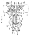
- FIG. 4 exemplifies an in-wheel motor of the present invention and means for mounting the in-wheel motor while other structural features are omitted.
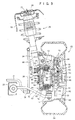
- FIG. 5 is a longitudinal sectional view of the in-wheel motor according to the present invention.
- a drive motor 1200 in a drive mechanism 1100 is a permanent-magnet-type AC motor, particularly a 6-phase synchronous AC motor.
- a casing 1210 of the drive motor 1200 includes an outer frame 1211, an end ring 1213, and an end plate 1214.
- the outer frame 1211 is cylindrical and includes a bracket portion 1211a, which is located at the right-hand side thereof in FIG. 5.
- a stator 1220 which is composed of a stator core 1221 and a coil 1222, is mounted on the inner circumferential surface of the outer frame 1211. In order to reduce idle space, the number of poles of the coil 1222 is six, and the coil 1222 uses thin wires. Also, in order to reduce the axial length of the drive motor 1200, coil ends are mechanically compressed from opposite sides. Reference letters A and B denote attachments.
- a rotor 1240 includes a rotor core 1241 and a permanent magnet 1242.
- Rotary shaft blocks 1251 and 1252 which constitute a rotary shaft of the drive motor 1200, are attached to the rotor core 1241 via bolts.
- a shaft portion 1251a of the rotary shaft block 1251 is supported rotatably by means of a motor bearing 1231, which is fixedly attached to the end ring 1213.
- a revolution speed detector 1260 such as a resolver is attached to the left-hand end of the shaft portion 1251a.
- a shaft portion 1252a of the rotary shaft block 1252 is supported rotatably by means of a motor bearing 1232, which is fixedly attached to the bracket portion 1211a of the outer frame 1211. Serrations are formed on the inner surface of the shaft portion 1252a, so that the shaft portion 1252a is spline-coupled to an input shaft 1270 of a reduction gear mechanism 1300.
- a housing 1411 houses the reduction gear mechanism 1300.
- a wheel bearing i.e., a hub bearing 1440, is fixedly attached to the outer circumference of a wheel shaft tube portion 1411a of the housing 1411.
- the housing 1411 is attached via bolts 1215 to the bracket portion 1211a of the outer frame 1211 of the drive motor 1200.
- a revolution speed signal indicative of revolution speed detected by the revolution speed detector 1260 is output via a cable 1281.
- the reduction gear mechanism 1300 is implemented by means of a planetary gear mechanism and adapted to reduce the revolution speed of the input shaft 1270 to thereby transmit the reduced revolution speed to a wheel shaft 1410.
- a partition 1302 is provided within a gear chamber for controlling stirring of lubrication oil.
- the planetary gear mechanism may be of a single stage or a plurality of stages.
- a ring gear 1303 of the planetary gear mechanism is provided on the inner surface of the housing 1411.
- a carrier 1301 is spline-coupled to the wheel shaft 1410 so as to transmit torque to the wheel shaft 1410 while being allowed to move axially.
- the wheel shaft 1410 is disposed within the wheel shaft tube portion 1411a of the housing 1411.
- a brake 1400 is a mechanical drum brake.
- a back plate 1403 of the brake 1400 is fixedly attached to an end face of the housing 1411.
- a wheel hub 1420 is attached to the wheel shaft 1410 via bolts.
- a brake drum 1430 and a disk wheel 1505 of a wheel are attached to the wheel hub 1420 via bolts.
- a hub bearing 1440 is interposed between the wheel shaft tube portion 1411a and the wheel hub 1420.
- the brake 1400 operates in the following manner. As hydraulic pressure increases as a result of a brake pedal being stepped on, a wheel cylinder 1401 causes brake shoes 1402 to be expanded, so that the brake shoes 1402 come into contact with the brake drum 1430 for braking.
- a tire 1500 is mounted on a rim 1510 of the disk wheel 1505.
- the drive mechanism 1100 when the drive motor 1200 is activated to thereby rotate the rotor 1240, rotation of the rotor 1240 is transmitted to the rotary shaft block 1252 and the input shaft 1270 of the reduction gear mechanism 1300 and is then speed-reduced at the reduction gear mechanism 1300.
- the speed-reduced rotation is transmitted to the wheel shaft 1410.
- the tire 1500 is rotated via the wheel hub 1420 coupled to the wheel shaft 1410, whereby the electric vehicle moves.
- An upper mounting block 800 and a lower mounting block 810 are integrally formed on the casing 1210 of the drive motor at an upper portion of the casing 1210 and at a lower portion of the casing 1210, respectively.
- the upper mounting block 800 is formed on an upper portion of the casing 1210 and assumes a substantially platelike shape.
- Coupling surfaces 801a and 801b are formed on the corresponding end faces of the substantially platelike mounting block 800, the end faces extending along the longitudinal direction of the casing 1210.
- a plurality of female screw portions (not shown) are formed on each of the coupling surfaces 801a and 801b.
- the lower mounting block 810 is formed on a lower portion of the casing 1210 and assumes a substantially platelike shape. Coupling surfaces 811a and 811b are formed on the corresponding end faces of the substantially platelike mounting block 810, the end faces extending along the longitudinal direction of the casing 1210. A plurality of female screw portions are formed on each of the coupling surfaces 811a and 811b. That is, the upper mounting block 800 has the coupling surfaces 801a and 801b, to which an upper arm 600 is attached, and the lower mounting block 810 has the coupling surfaces 811a and 811b, to which a lower arm 700 is attached.
- the shape of the coupling surfaces, the angle of the coupling surfaces with respect to a horizontal plane and the like can be designed arbitrarily.
- the angles of the coupling surfaces determine the angles of coupling portions 601a and 601b of the upper arm 600, which abut the upper mounting block 800, and the angles of coupling portions 701a and 701b of the lower arm 700, which abut the lower mounting block 810.
- Reference numerals 604a, 604b, 704a, and 704b denote locking screws to be engaged with female screws formed in the coupling surfaces.
- the upper arm 600 includes a support portion 603, arm portions 602a and 602b, and the coupling portions 601a and 601b.
- the coupling portions 601a and 601b are formed so as to abut the coupling surfaces 801a and 801b, respectively, of the upper mounting block 800.
- the arm portions 602a and 602b are shaped so as to extend between the support portion 603 and the coupling portions 601a and 601b.
- the shape of the arm portions 602a and 602b must be determined so as to exhibit sufficient strength and rigidity to endure the weight of the vehicle and an impact force transmitted from the wheel to the support portion 603 and a support portion 703, which will be described later.
- a ball joint mechanism 612 or a spherical joint mechanism is coupled to the support portion 603.
- the ball joint mechanism 612 assumes a known structure.
- a taper shaft 609 of the ball joint mechanism 612 is inserted into a through-hole 608 formed in the support portion 603 and locked by means of a nut 610.
- An upper arm of an unillustrated suspension mechanism is attached to a suspension attachment portion 605 of the ball joint mechanism 612.
- a coupling 613, to which a steering tie rod is coupled, is provided on the support portion 603 and located away from the through-hole 608.
- the tie rod coupling 613 may be provided on the lower arm 700, which will be described later.
- the shaft 609 is inclined at a predetermined angle with respect to the horizontal plane of the support portion 603.
- the king pin angle ⁇ is determined in view of steering stability of a vehicle and the like.
- the lower arm 700 includes a support portion 703, arm portions 702a and 702b, and the coupling portions 701a and 701b.
- the support portion 703 assumes a flat-plate shape and is disposed horizontally while being located away from the bottom surface of the lower mounting block 810 of the casing 1210.
- the coupling portions 701a and 701b are formed so as to abut the coupling surfaces 811a and 811b, respectively, of the lower mounting block 810.
- the arm portions 702a and 702b are shaped so as to extend between the support portion 703 and the coupling portions 701a and 701b.
- the shape of the arm portions 702a and 702b must be determined so as to exhibit sufficient strength and rigidity to endure the weight of the vehicle and an impact force transmitted from the wheel to the support portion 703.
- the ball joint mechanism 712 assumes a known structure.
- a taper shaft 709 of the ball joint mechanism 712 is inserted into a through-hole 708 formed in the support portion 703 and locked by means of a nut 710.
- a suspension attachment portion 705 of the ball joint mechanism 712 is attached to a lower arm of a suspension mechanism (not shown). As shown in FIG. 5, the shaft 709 is inclined at a predetermined angle with respect to the horizontal plane of the support portion 703.
- the shaft 709 of the ball joint mechanism 712 is provided such that the axis thereof is aligned with the axis of the shaft 609 of the ball joint mechanism 612. As mentioned above, this alignment feature is employed in view of steering stability of a vehicle and the like.
- the present invention is characterized in that, in the in-wheel motor described above in (1), (2), and (3), the support portions 603 and 703 of the arms 600 and 700 are coupled to the suspension mechanism via the ball joint mechanisms 612 and 712 or respective spherical joint mechanisms.
- the present invention is characterized in that the ring gear 1303 of the reduction gear mechanism 1300, which reduces the revolution speed of the drive motor and transmits the reduced revolution speed to the wheel, is formed on the inner surface of the housing 1411, which is a member separate from the motor casing 1210; the input shaft 1270 of the reduction gear mechanism 1300 is spline-coupled to the shaft portion 1252a of the drive motor; and the housing 1411 is removably attached to the casing 1210 via bolts.
- the present invention yields the following effects.
- Only the upper and lower mounting blocks are formed on an in-wheel motor body such that coupling surfaces of the blocks are common among different types of vehicles.
- a plurality of types of upper and lower arms are prepared such that, while coupling specifications are common among the upper arms and among the lower arms, other specifications of the upper and lower arms are modified according to, for example, mounting height.
- An upper arm and a lower arm are selected from the prepared upper and lower arms as appropriate for individual applications.
- the upper and lower mounting blocks are coupled to a suspension mechanism by means of the thus-selected upper and lower arms.
- the present invention allows a wheel drive section including a speed reduction mechanism to be separated from a drive motor. Therefore, through change in the gear ratio of a reduction gear apparatus, the revolution speed of a wheel and driving torque can be changed, whereby tire diameter can be selected freely without need to replace a drive motor.
- the in-wheel motor of the present invention can cope with changes in specifications and performance of a vehicle through replacement of units and is favorably used in an electric vehicle.
Landscapes
- Engineering & Computer Science (AREA)
- Power Engineering (AREA)
- Chemical & Material Sciences (AREA)
- Combustion & Propulsion (AREA)
- Transportation (AREA)
- Mechanical Engineering (AREA)
- Arrangement Or Mounting Of Propulsion Units For Vehicles (AREA)
- Electric Propulsion And Braking For Vehicles (AREA)
- Connection Of Motors, Electrical Generators, Mechanical Devices, And The Like (AREA)
- Vehicle Body Suspensions (AREA)
Abstract
Description
Claims (9)
- An in-wheel motor for an electric vehicle comprising a drive motor, a reduction gear mechanism, a wheel bearing, and a mechanical brake and serving as a drive apparatus for an electric vehicle,
said in-wheel motor being characterized in that said drive motor includes a casing which houses a rotor and a stator; said reduction gear mechanism comprises a planetary gear mechanism; a wheel bearing is fixedly attached to an outer circumference of an end portion of a housing, which houses a wheel shaft coupled to an output element of said planetary gear mechanism; mounting blocks having engagement means are provided respectively at upper and lower outside portions of said casing; and attachments are attached to said corresponding mounting blocks and joined to corresponding joint mechanisms, which are movably coupled to a suspension mechanism. - An in-wheel motor for an electric vehicle as described in claim 1, wherein said attachments are characterized in that a line connecting centers of rotation of said joint mechanisms, which are fixedly attached to said corresponding attachments, forms a king pin angle with respect to a center axis of a wheel.
- An in-wheel motor for an electric vehicle as described in claim 1, wherein a steering tie rod is coupled to either of said attachments.
- An in-wheel motor for an electric vehicle comprising a drive motor, a reduction gear mechanism, a wheel bearing, and a mechanical brake and serving as a drive apparatus for an electric vehicle,
said in-wheel motor being characterized in that said drive motor includes a casing which houses a rotor and a stator; said reduction gear mechanism comprises a planetary gear mechanism; a wheel bearing is fixedly attached to an outer circumference of an end portion of a housing, which houses a wheel shaft coupled to an output element of said planetary gear mechanism; said mechanical brake is a drum brake or a disk brake; said planetary gear mechanism is housed within said housing, and an input shaft of said planetary gear mechanism is spline-coupled to a rotary shaft of said drive motor; and said housing is attached to said casing via bolts. - An in-wheel motor for an electric vehicle as described in claim 4, wherein said planetary gear mechanism is configured such that a partition is provided within a gear chamber for controlling stirring of lubrication oil.
- An in-wheel motor for an electric vehicle as described in claim 1 or 4, wherein a rotational-position detector is disposed on a side of said rotor opposite an output side of said rotor, and said rotational-position detector is a resolver.
- An in-wheel motor for an electric vehicle as described in claim 1 or 4, wherein said drive motor is a 6-phase synchronous AC motor.
- An in-wheel motor for an electric vehicle as described in claim 1 or 4, wherein coil ends of an armature, which partially constitutes said stator, are mechanically compressed from axially opposite sides.
- An in-wheel motor for an electric vehicle as described in claim 1 or 4, wherein said joint mechanism is a ball joint mechanism or a spherical joint mechanism.
Priority Applications (1)
| Application Number | Priority Date | Filing Date | Title |
|---|---|---|---|
| EP05019094A EP1600324B1 (en) | 2001-02-19 | 2001-12-26 | In-wheel motor for electric vehicle |
Applications Claiming Priority (3)
| Application Number | Priority Date | Filing Date | Title |
|---|---|---|---|
| JP2001041698 | 2001-02-19 | ||
| JP2001041698A JP3440082B2 (en) | 2001-02-19 | 2001-02-19 | In-wheel motor for electric vehicles |
| PCT/JP2001/011434 WO2002066280A1 (en) | 2001-02-19 | 2001-12-26 | In-wheel motor for electric automobiles |
Related Child Applications (1)
| Application Number | Title | Priority Date | Filing Date |
|---|---|---|---|
| EP05019094A Division EP1600324B1 (en) | 2001-02-19 | 2001-12-26 | In-wheel motor for electric vehicle |
Publications (3)
| Publication Number | Publication Date |
|---|---|
| EP1362736A1 true EP1362736A1 (en) | 2003-11-19 |
| EP1362736A4 EP1362736A4 (en) | 2005-08-17 |
| EP1362736B1 EP1362736B1 (en) | 2006-06-07 |
Family
ID=18904100
Family Applications (2)
| Application Number | Title | Priority Date | Filing Date |
|---|---|---|---|
| EP01995010A Expired - Lifetime EP1362736B1 (en) | 2001-02-19 | 2001-12-26 | In-wheel motor for electric automobiles |
| EP05019094A Expired - Lifetime EP1600324B1 (en) | 2001-02-19 | 2001-12-26 | In-wheel motor for electric vehicle |
Family Applications After (1)
| Application Number | Title | Priority Date | Filing Date |
|---|---|---|---|
| EP05019094A Expired - Lifetime EP1600324B1 (en) | 2001-02-19 | 2001-12-26 | In-wheel motor for electric vehicle |
Country Status (6)
| Country | Link |
|---|---|
| US (1) | US6942049B2 (en) |
| EP (2) | EP1362736B1 (en) |
| JP (1) | JP3440082B2 (en) |
| CN (1) | CN1239337C (en) |
| DE (2) | DE60120499T2 (en) |
| WO (1) | WO2002066280A1 (en) |
Cited By (13)
| Publication number | Priority date | Publication date | Assignee | Title |
|---|---|---|---|---|
| EP1630026A3 (en) * | 2004-08-25 | 2006-03-22 | Toyota Jidosha Kabushiki Kaisha | Housing structure of in-wheel motor |
| US7379808B2 (en) | 2004-10-20 | 2008-05-27 | Bayerische Motoren Werke Aktiengesellschaft | Longitudinal dynamics control system in motor vehicles |
| US7658251B2 (en) | 2006-09-20 | 2010-02-09 | James Harry K | Direct drive electric traction motor |
| US7958959B2 (en) | 2004-05-17 | 2011-06-14 | Toyota Jidosha Kabushiki Kaisha | Mounting structure for a part provided to an enclosure of an in-wheel motor |
| WO2013041141A1 (en) * | 2011-09-22 | 2013-03-28 | Schaeffler Technologies AG & Co. KG | Wheel suspension device with wheel bearing support connected thereto in a steerable manner and with an integrated wheel drive motor |
| EP2551139A4 (en) * | 2010-03-25 | 2013-11-20 | Ntn Toyo Bearing Co Ltd | In-wheel motor-driven device |
| WO2013159844A3 (en) * | 2012-04-24 | 2014-04-17 | Daimler Ag | Rotor support for an electrical machine, support element for a rotor support and method of producing a support element |
| EP2666654A4 (en) * | 2011-01-21 | 2014-07-02 | Ntn Toyo Bearing Co Ltd | In-wheel motor drive device |
| WO2015144528A1 (en) * | 2014-03-25 | 2015-10-01 | Compagnie Generale Des Etablissements Michelin | Motor-driven hub for an electric drive vehicle |
| EP2962886A3 (en) * | 2014-06-11 | 2016-04-27 | Kanzaki Kokyukoki Mfg. Co., Ltd. | Electric motor driving device and planetary gear unit |
| CN107848403A (en) * | 2016-04-06 | 2018-03-27 | Ntn株式会社 | In-wheel motor drive unit |
| EP3441247A4 (en) * | 2016-04-06 | 2019-12-11 | NTN Corporation | WHEEL POWER SUPPLY LINE WIRING STRUCTURE AND WHEEL MOTOR DRIVE DEVICE |
| EP3652011B1 (en) * | 2017-07-14 | 2022-03-16 | Robert Bosch GmbH | Wheel assembly for an electric vehicle |
Families Citing this family (90)
| Publication number | Priority date | Publication date | Assignee | Title |
|---|---|---|---|---|
| US20050127856A1 (en) * | 2002-07-31 | 2005-06-16 | Wavecrest Laboratories | Low-voltage electric motors |
| US20050052080A1 (en) * | 2002-07-31 | 2005-03-10 | Maslov Boris A. | Adaptive electric car |
| US20040263099A1 (en) * | 2002-07-31 | 2004-12-30 | Maslov Boris A | Electric propulsion system |
| JP4639572B2 (en) * | 2002-12-13 | 2011-02-23 | トヨタ自動車株式会社 | Electric car |
| US8839891B2 (en) | 2003-02-21 | 2014-09-23 | Lockheed Martin Corporation | Multi-mode skid steering |
| US20050023052A1 (en) | 2003-02-21 | 2005-02-03 | Beck Michael S. | Vehicle having an articulated suspension and method of using same |
| US7464775B2 (en) | 2003-02-21 | 2008-12-16 | Lockheed Martin Corporation | Payload module for mobility assist |
| US7150340B2 (en) * | 2003-02-21 | 2006-12-19 | Lockheed Martin Corporation | Hub drive and method of using same |
| DE10338659A1 (en) * | 2003-08-22 | 2005-03-17 | Magnet-Motor Gesellschaft Für Magnetmotorische Technik Mbh | Electric drive unit for a motor vehicle |
| JP2005104216A (en) * | 2003-09-29 | 2005-04-21 | Ntn Corp | Electric wheel drive device |
| US7703780B2 (en) * | 2003-09-30 | 2010-04-27 | Toyota Jidosha Kabushiki Kaisha | Wheel supporting apparatus improving ride comfort of vehicle |
| JP4113506B2 (en) * | 2003-09-30 | 2008-07-09 | トヨタ自動車株式会社 | Wheel support device |
| CN1298561C (en) * | 2004-03-12 | 2007-02-07 | 清华大学 | Electric machine driving device used on light electromobile |
| JP4694148B2 (en) * | 2004-05-28 | 2011-06-08 | トヨタ自動車株式会社 | Motor parts |
| JP2006027529A (en) * | 2004-07-20 | 2006-02-02 | Toyota Motor Corp | An electric drive device for a vehicle and an automobile equipped with the same. |
| JP2006188153A (en) | 2005-01-06 | 2006-07-20 | Toyota Motor Corp | In-wheel motor |
| JP4799199B2 (en) * | 2005-02-16 | 2011-10-26 | Ntn株式会社 | In-wheel motor drive device |
| JP2007022386A (en) | 2005-07-19 | 2007-02-01 | Ntn Corp | Electric wheel driving device |
| DE102005034278A1 (en) * | 2005-07-22 | 2007-04-12 | Daimlerchrysler Ag | Drive unit for a vehicle |
| JP4894215B2 (en) * | 2005-10-05 | 2012-03-14 | 日産自動車株式会社 | In-wheel drive unit |
| US7552787B1 (en) * | 2005-10-07 | 2009-06-30 | Williams Kevin R | Energy recoverable wheel motor |
| US7579738B2 (en) * | 2005-10-31 | 2009-08-25 | Greenee Energy Inc. | Multi-phase electrical motor for use in a wheel |
| JP4965131B2 (en) * | 2006-01-27 | 2012-07-04 | トヨタ自動車株式会社 | In-wheel motor |
| DE102006030502A1 (en) * | 2006-07-01 | 2008-01-03 | Voith Patent Gmbh | Roller drive end and method for mounting a drive device on a drive pin |
| JP4501909B2 (en) * | 2006-08-11 | 2010-07-14 | トヨタ自動車株式会社 | In-wheel motor structure |
| US7445067B2 (en) | 2006-08-31 | 2008-11-04 | American Axle & Manufacturing, Inc. | Electric wheel motor assembly |
| ITTO20060894A1 (en) | 2006-12-15 | 2008-06-16 | Oto Melara Spa | MOTORIZED WHEEL FOR A MILITARY VEHICLE |
| JP2009067176A (en) * | 2007-09-12 | 2009-04-02 | Yanmar Co Ltd | Working vehicle |
| US8387381B2 (en) * | 2008-01-31 | 2013-03-05 | Hitachi, Ltd. | Electric booster |
| JP4667478B2 (en) * | 2008-02-26 | 2011-04-13 | 日立建機株式会社 | Traveling device |
| JP4877296B2 (en) | 2008-08-21 | 2012-02-15 | トヨタ自動車株式会社 | DRIVE DEVICE AND CONTROL DEVICE THEREOF |
| JP4806461B2 (en) * | 2008-09-26 | 2011-11-02 | 三洋電機株式会社 | Electric motor and electric vehicle |
| IT1392130B1 (en) * | 2008-11-03 | 2012-02-22 | Eden Technology Srl | AUTOMATIC STEERING DEVICE FOR LIFTING TRUCKS AND MANUFACTURED TRANSPORT TRUCKS. |
| JP5141614B2 (en) * | 2009-03-25 | 2013-02-13 | アイシン精機株式会社 | In-wheel motor unit |
| CN101549636B (en) * | 2009-05-15 | 2013-02-20 | 沈阳罗特自动化技术有限公司 | Over loading servo wheel unit |
| JP4779039B2 (en) * | 2009-07-02 | 2011-09-21 | 株式会社福本ボデー | Self-propelled vacuum cleaner |
| DE102009038423A1 (en) | 2009-08-21 | 2011-03-10 | Audi Ag | Device for adjusting camber and / or track |
| DE102009038928A1 (en) | 2009-08-26 | 2010-11-04 | Schaeffler Technologies Gmbh & Co. Kg | Electric motor e.g. ring motor, for use as wheel hub motor in e.g. car, has stator, rotor and air gap, where air gap is formed between stator and rotor, and size of gap is variable depending on number of revolutions of motor |
| DE102010049610A1 (en) * | 2009-12-07 | 2011-06-09 | Schaeffler Technologies Gmbh & Co. Kg | Electric drive unit for a motor vehicle |
| JP2011240765A (en) * | 2010-05-17 | 2011-12-01 | Ntn Corp | In-wheel motor driving device |
| DE102010040763A1 (en) * | 2010-09-14 | 2012-03-15 | Bayerische Motoren Werke Aktiengesellschaft | Independent suspension of a non-steerable driven wheel of a two-lane vehicle |
| CN103299516A (en) * | 2011-01-11 | 2013-09-11 | 株式会社捷太格特 | Motor Drive Transmission |
| JP2012171428A (en) * | 2011-02-18 | 2012-09-10 | Ntn Corp | In-wheel motor driving apparatus |
| KR101301754B1 (en) * | 2011-05-23 | 2013-08-29 | 현대모비스 주식회사 | In-wheel driving apparatus |
| KR20120137030A (en) * | 2011-06-10 | 2012-12-20 | 현대모비스 주식회사 | Friction brake type in-wheel working device |
| JP2013023202A (en) * | 2011-07-15 | 2013-02-04 | Tadashi Takano | Electric wheel |
| CN103534121B (en) | 2011-08-02 | 2016-02-10 | 日本精工株式会社 | Hub bearing, speed reduction gearing and in-wheel motor |
| NL2007261C2 (en) * | 2011-08-12 | 2013-02-13 | E Traction Europe Bv | In-wheel motor with brake. |
| JP5792015B2 (en) * | 2011-09-27 | 2015-10-07 | Ntn株式会社 | In-wheel motor drive device |
| KR101665215B1 (en) * | 2011-12-27 | 2016-10-11 | 가츠지 오쿠다 | Wheel-axle generator |
| JP2013163401A (en) * | 2012-02-09 | 2013-08-22 | Nsk Ltd | Driving unit |
| GB2487872B (en) * | 2012-05-09 | 2012-12-26 | Protean Electric Ltd | An electric motor or generator system |
| KR101903971B1 (en) * | 2012-07-11 | 2018-10-04 | 현대모비스 주식회사 | In wheel driven apparatus |
| JP6195432B2 (en) * | 2012-10-03 | 2017-09-13 | Ntn株式会社 | In-wheel motor drive device |
| US9561715B2 (en) * | 2012-11-16 | 2017-02-07 | Deere & Company | Wheel hub with electric motor |
| CN103001389B (en) * | 2012-12-17 | 2015-12-09 | 无锡浜马通用机械制造有限公司 | The automobile-used built-in motor of electrical salf-walking |
| US9553414B2 (en) | 2013-07-04 | 2017-01-24 | Nissan Motor Co., Ltd. | Motor power feed wiring structure having a vehicle body-side power feed wire rotatably connected to a motor-side power feed wire |
| JP2015089188A (en) * | 2013-10-29 | 2015-05-07 | Ntn株式会社 | In-wheel motor and in-wheel motor drive unit |
| JP6313610B2 (en) * | 2014-02-27 | 2018-04-18 | Ntn株式会社 | CONNECTION STRUCTURE OF IN-WHEEL MOTOR DRIVE DEVICE AND DAMPER AND SUSPENSION DEVICE PROVIDED WITH THIS CONNECTION |
| FR3021910B1 (en) * | 2014-06-05 | 2018-12-07 | Valeo Systemes De Controle Moteur | STATOR ASSEMBLY FOR WHEEL MOTOR AND ITS RACK HOLDER. |
| WO2015198679A1 (en) * | 2014-06-27 | 2015-12-30 | 日産自動車株式会社 | Unsprung power supply apparatus for in-wheel motor vehicle |
| JP6331770B2 (en) * | 2014-06-27 | 2018-05-30 | 日産自動車株式会社 | In-wheel motor steered wheel suspension system |
| US9624998B2 (en) * | 2014-07-30 | 2017-04-18 | Tenneco Automotive Operating Company Inc. | Electromagnetic flywheel damper and method therefor |
| JP6490376B2 (en) * | 2014-09-26 | 2019-03-27 | 株式会社村上商会 | Electric vehicle drive system |
| US9550402B2 (en) * | 2015-04-13 | 2017-01-24 | Reyco Granning, Llc | Independent front suspension module for installation into a vehicle |
| JP6125066B1 (en) * | 2016-03-08 | 2017-05-10 | Ntn株式会社 | In-wheel motor drive device |
| EP3444497B1 (en) * | 2016-04-15 | 2021-03-03 | Minebea Mitsumi Inc. | Wheel module |
| JP6757630B2 (en) * | 2016-08-30 | 2020-09-23 | Ntn株式会社 | In-wheel motor drive |
| JP6706563B2 (en) * | 2016-09-23 | 2020-06-10 | Ntn株式会社 | Suspension structure for in-wheel motor drive |
| JP6823417B2 (en) * | 2016-09-30 | 2021-02-03 | Ntn株式会社 | In-wheel motor drive |
| JP6125083B1 (en) * | 2016-10-17 | 2017-05-10 | Ntn株式会社 | In-wheel motor drive device |
| JP6786354B2 (en) * | 2016-10-31 | 2020-11-18 | Ntn株式会社 | In-wheel motor drive |
| KR101841009B1 (en) * | 2016-11-01 | 2018-03-23 | 현대모비스 주식회사 | In-wheel working device |
| JP7029287B2 (en) * | 2016-12-26 | 2022-03-03 | Ntn株式会社 | In-wheel motor drive |
| CN106915391B (en) * | 2017-02-21 | 2019-04-05 | 中国科学院合肥物质科学研究院 | A kind of stalk class plant height Dynamic Recognition platform based on SICK laser sensor |
| JP6760198B2 (en) * | 2017-05-16 | 2020-09-23 | トヨタ自動車株式会社 | Non-steering drive wheel suspension device with built-in in-wheel motor |
| CN107370291B (en) * | 2017-08-23 | 2019-10-18 | 东阳市俊华电器销售有限公司 | A magnetic control wheel based on electromagnetic propulsion system |
| JP7084262B2 (en) * | 2018-09-13 | 2022-06-14 | Ntn株式会社 | In-wheel motor drive |
| CN109130839B (en) * | 2018-10-09 | 2020-06-30 | 清华大学 | Electric wheel assembly suitable for double tires and provided with wheels, axle and vehicle |
| KR102117885B1 (en) * | 2018-12-05 | 2020-06-04 | 현대트랜시스 주식회사 | In-wheel working device |
| ES2790025A1 (en) * | 2019-04-26 | 2020-10-26 | Scutum Logistic S L | DRIVE WHEEL WITH ELECTRIC MOTOR INTEGRATED IN THE AXLE (Machine-translation by Google Translate, not legally binding) |
| JP7329460B2 (en) | 2020-01-28 | 2023-08-18 | 充治 駒田 | Electric vehicle and its manufacturing method |
| JP7349961B2 (en) * | 2020-06-08 | 2023-09-25 | Ntn株式会社 | Bearings for vehicle power units and wheels with generators |
| KR102466954B1 (en) * | 2020-10-13 | 2022-11-15 | 주식회사 진우에스엠씨 | Wheel Assembly Mounting Inwheel Motor |
| DE102021202447A1 (en) * | 2021-03-12 | 2022-09-15 | Robert Bosch Gesellschaft mit beschränkter Haftung | Drive assembly for a vehicle |
| KR20230011139A (en) * | 2021-07-13 | 2023-01-20 | 현대모비스 주식회사 | Wheel structure including hub bearing and vehicle including the same |
| KR102760129B1 (en) * | 2022-03-02 | 2025-01-24 | 현대모비스 주식회사 | Power transmission device and automobile including the same |
| KR102813723B1 (en) * | 2022-10-24 | 2025-05-27 | 엘지전자 주식회사 | Robot wheel driving apparatus |
| WO2024175197A1 (en) * | 2023-02-23 | 2024-08-29 | Elaphe Propulsion Technologies Ltd. | Symmetric in-wheel electric motor design |
| CN119872484B (en) * | 2025-03-26 | 2025-06-24 | 吉林大学 | Linear control braking device, braking system and braking method based on angle module |
Family Cites Families (25)
| Publication number | Priority date | Publication date | Assignee | Title |
|---|---|---|---|---|
| GB1159499A (en) * | 1967-03-02 | 1969-07-23 | Pratt Prec Hydraulics Ltd | Improvements in or relating to Electrical Stepping Motors |
| JPS59103549A (en) * | 1982-12-01 | 1984-06-15 | Hitachi Ltd | coil insertion device |
| AU573991B2 (en) * | 1986-03-27 | 1988-06-23 | Kubota Ltd. | Steering apparatus for a front wheel drive tractor |
| JP2769323B2 (en) * | 1988-06-29 | 1998-06-25 | アイシン・エィ・ダブリュ株式会社 | Motor drive device with reduction gear and electric vehicle |
| GB2250142B (en) * | 1990-11-20 | 1994-11-09 | Aisin Aw Co | Drive gear disposition in a wheel motor |
| JP2896225B2 (en) * | 1990-11-20 | 1999-05-31 | アイシン・エィ・ダブリュ株式会社 | Wheel motor lubrication device |
| US5180180A (en) * | 1991-04-24 | 1993-01-19 | Aisin Aw Co., Ltd. | Wheel supporting apparatus |
| US5087229A (en) * | 1991-05-06 | 1992-02-11 | General Motors Corporation | Independently suspended steerable motor wheel apparatus |
| JP3094344B2 (en) * | 1991-10-29 | 2000-10-03 | 東京電力株式会社 | Electric wheels for electric vehicles |
| JP3094345B2 (en) * | 1991-10-29 | 2000-10-03 | 東京電力株式会社 | Wheel motor |
| US5382854A (en) * | 1992-07-29 | 1995-01-17 | Kabushikikaisha Equos Research | Electrical motor drive apparatus with planetary gearing |
| JP2545733B2 (en) * | 1993-09-17 | 1996-10-23 | 環境庁国立環境研究所長 | Electric vehicle drive |
| US5472059A (en) * | 1994-02-15 | 1995-12-05 | Dana Corporation | Wheel end assembly |
| MY119161A (en) | 1994-04-18 | 2005-04-30 | Novartis Ag | Delta-amino-gamma-hydroxy-omega-aryl-alkanoic acid amides with enzyme especially renin inhibiting activities |
| JP3526093B2 (en) * | 1994-12-09 | 2004-05-10 | 本田技研工業株式会社 | Manufacturing method of motor with reduction gear |
| JPH09109696A (en) * | 1995-10-23 | 1997-04-28 | Honda Motor Co Ltd | Wheel motor unit and electric vehicle |
| US5906249A (en) * | 1995-12-22 | 1999-05-25 | Orion-yhtyma Oy | Drive system of a drive wheel |
| JP3814922B2 (en) * | 1997-03-21 | 2006-08-30 | 松下電器産業株式会社 | Magnet motor |
| JPH1189178A (en) | 1997-09-08 | 1999-03-30 | Meidensha Corp | In-wheel motor for electric vehicle |
| JP3666543B2 (en) * | 1997-10-14 | 2005-06-29 | ふそうエンジニアリング株式会社 | Electric vehicle motor mounting structure |
| JPH11170831A (en) | 1997-12-09 | 1999-06-29 | Araco Corp | Suspension device for electric vehicle |
| ITPD980138A1 (en) * | 1998-05-29 | 1999-11-29 | Carraro Spa | STEERING MOTOR AXLE |
| JP4433504B2 (en) * | 1998-08-06 | 2010-03-17 | 株式会社エクォス・リサーチ | Electric vehicle |
| IT1304666B1 (en) * | 1998-10-01 | 2001-03-28 | Plaset Spa | SYNCHRONOUS ELECTRIC MOTOR. |
| JP3772638B2 (en) | 2000-05-09 | 2006-05-10 | 日産自動車株式会社 | Wheel-in motor vehicle motor mounting structure |
-
2001
- 2001-02-19 JP JP2001041698A patent/JP3440082B2/en not_active Expired - Fee Related
- 2001-12-26 US US10/239,876 patent/US6942049B2/en not_active Expired - Fee Related
- 2001-12-26 DE DE60120499T patent/DE60120499T2/en not_active Expired - Lifetime
- 2001-12-26 DE DE60124326T patent/DE60124326T2/en not_active Expired - Lifetime
- 2001-12-26 EP EP01995010A patent/EP1362736B1/en not_active Expired - Lifetime
- 2001-12-26 WO PCT/JP2001/011434 patent/WO2002066280A1/en not_active Ceased
- 2001-12-26 EP EP05019094A patent/EP1600324B1/en not_active Expired - Lifetime
- 2001-12-26 CN CNB018083501A patent/CN1239337C/en not_active Expired - Fee Related
Cited By (24)
| Publication number | Priority date | Publication date | Assignee | Title |
|---|---|---|---|---|
| DE112005001122B8 (en) * | 2004-05-17 | 2016-09-01 | Toyota Jidosha Kabushiki Kaisha | A fixing structure for a part provided at an outer peripheral portion of a worm-motor enclosure |
| DE112005001122B4 (en) * | 2004-05-17 | 2016-04-28 | Toyota Jidosha Kabushiki Kaisha | Fixing structure of a part |
| US7958959B2 (en) | 2004-05-17 | 2011-06-14 | Toyota Jidosha Kabushiki Kaisha | Mounting structure for a part provided to an enclosure of an in-wheel motor |
| US8157036B2 (en) | 2004-05-17 | 2012-04-17 | Aisin Seiki Kabushiki Kaisha | Mounting structure of part |
| EP2106948A1 (en) | 2004-08-25 | 2009-10-07 | Toyota Jidosha Kabushiki Kaisha | Housing structure of in-wheel motor |
| US7735589B2 (en) | 2004-08-25 | 2010-06-15 | Toyota Jidosha Kabushiki Kaisha | Housing structure of in-wheel motor |
| EP1630026A3 (en) * | 2004-08-25 | 2006-03-22 | Toyota Jidosha Kabushiki Kaisha | Housing structure of in-wheel motor |
| US7379808B2 (en) | 2004-10-20 | 2008-05-27 | Bayerische Motoren Werke Aktiengesellschaft | Longitudinal dynamics control system in motor vehicles |
| US7658251B2 (en) | 2006-09-20 | 2010-02-09 | James Harry K | Direct drive electric traction motor |
| EP2551139A4 (en) * | 2010-03-25 | 2013-11-20 | Ntn Toyo Bearing Co Ltd | In-wheel motor-driven device |
| US9302578B2 (en) | 2010-03-25 | 2016-04-05 | Ntn Corporation | In-wheel motor-driven device |
| EP2666654A4 (en) * | 2011-01-21 | 2014-07-02 | Ntn Toyo Bearing Co Ltd | In-wheel motor drive device |
| US9340103B2 (en) | 2011-01-21 | 2016-05-17 | Ntn Corporation | In-wheel motor drive device |
| WO2013041141A1 (en) * | 2011-09-22 | 2013-03-28 | Schaeffler Technologies AG & Co. KG | Wheel suspension device with wheel bearing support connected thereto in a steerable manner and with an integrated wheel drive motor |
| WO2013159844A3 (en) * | 2012-04-24 | 2014-04-17 | Daimler Ag | Rotor support for an electrical machine, support element for a rotor support and method of producing a support element |
| FR3019106A1 (en) * | 2014-03-25 | 2015-10-02 | Michelin & Cie | MOTORIZED HUB FOR AN ELECTRIC TRACTION VEHICLE |
| WO2015144528A1 (en) * | 2014-03-25 | 2015-10-01 | Compagnie Generale Des Etablissements Michelin | Motor-driven hub for an electric drive vehicle |
| EP2962886A3 (en) * | 2014-06-11 | 2016-04-27 | Kanzaki Kokyukoki Mfg. Co., Ltd. | Electric motor driving device and planetary gear unit |
| CN107848403A (en) * | 2016-04-06 | 2018-03-27 | Ntn株式会社 | In-wheel motor drive unit |
| EP3441252A4 (en) * | 2016-04-06 | 2019-12-11 | NTN Corporation | MOTOR-WHEEL DRIVE DEVICE |
| EP3441247A4 (en) * | 2016-04-06 | 2019-12-11 | NTN Corporation | WHEEL POWER SUPPLY LINE WIRING STRUCTURE AND WHEEL MOTOR DRIVE DEVICE |
| US10632938B2 (en) | 2016-04-06 | 2020-04-28 | Ntn Corporation | In-wheel motor power line wiring structure and in-wheel motor drive device |
| EP3652011B1 (en) * | 2017-07-14 | 2022-03-16 | Robert Bosch GmbH | Wheel assembly for an electric vehicle |
| US11524568B2 (en) | 2017-07-14 | 2022-12-13 | Robert Bosch Gmbh | Electric vehicle and the wheel assembly thereof |
Also Published As
| Publication number | Publication date |
|---|---|
| CN1239337C (en) | 2006-02-01 |
| JP2002247713A (en) | 2002-08-30 |
| DE60124326D1 (en) | 2006-12-14 |
| DE60124326T2 (en) | 2007-03-29 |
| DE60120499D1 (en) | 2006-07-20 |
| US20040080223A1 (en) | 2004-04-29 |
| EP1600324A1 (en) | 2005-11-30 |
| DE60120499T2 (en) | 2006-11-16 |
| WO2002066280A1 (en) | 2002-08-29 |
| US6942049B2 (en) | 2005-09-13 |
| EP1362736B1 (en) | 2006-06-07 |
| JP3440082B2 (en) | 2003-08-25 |
| CN1424970A (en) | 2003-06-18 |
| EP1600324B1 (en) | 2006-11-02 |
| EP1362736A4 (en) | 2005-08-17 |
Similar Documents
| Publication | Publication Date | Title |
|---|---|---|
| EP1362736B1 (en) | In-wheel motor for electric automobiles | |
| US5087229A (en) | Independently suspended steerable motor wheel apparatus | |
| US6768932B2 (en) | Wheel motor system | |
| US7528518B2 (en) | In-wheel motor | |
| US7121367B2 (en) | Installation structure for electric rotating machine in motor vehicle | |
| US8316973B2 (en) | Electric driving unit for a vehicle | |
| US7597169B2 (en) | Wheel module | |
| KR101004598B1 (en) | Wheel structure for in-wheel motor mounting | |
| US20100155168A1 (en) | Wheel-adjacent motor configuration | |
| EP1734264A2 (en) | In-wheel motor system and method of installing in-wheel motor | |
| CN117163150A (en) | A steering system, corner module and vehicle | |
| CN1346754A (en) | Suspension system for vehicle | |
| CN216034294U (en) | In-wheel motor braking system | |
| CN1529671A (en) | Truck Knuckle Assembly | |
| CN207241414U (en) | A kind of chassis motorized structure using multi-connecting-rod separated suspension | |
| CN117446011A (en) | A corner module and vehicle | |
| JP2024514543A (en) | Reverse portal axle for use in low floor buses | |
| JP2004322802A (en) | Suspension device for motor driven vehicle | |
| CN220594637U (en) | Wheel end drive-by-wire module, wheel assembly and car | |
| EP4725735A1 (en) | In-wheel drive assembly for a vehicle | |
| CN220720733U (en) | Wheel hub unit, rear suspension structure and vehicle | |
| WO2018155679A1 (en) | Motorcycle | |
| CN118665152A (en) | Wheel hub drive system | |
| CN121268957A (en) | Vehicle corner module and vehicle | |
| CN121689664A (en) | Wheel hub motor for vehicle and delivery vehicle |
Legal Events
| Date | Code | Title | Description |
|---|---|---|---|
| PUAI | Public reference made under article 153(3) epc to a published international application that has entered the european phase |
Free format text: ORIGINAL CODE: 0009012 |
|
| 17P | Request for examination filed |
Effective date: 20021010 |
|
| AK | Designated contracting states |
Kind code of ref document: A1 Designated state(s): AT BE CH CY DE DK ES FI FR GB GR IE IT LI LU MC NL PT SE TR |
|
| RAP1 | Party data changed (applicant data changed or rights of an application transferred) |
Owner name: JAPAN SCIENCE AND TECHNOLOGY AGENCY |
|
| RAP1 | Party data changed (applicant data changed or rights of an application transferred) |
Owner name: JAPAN SCIENCE AND TECHNOLOGY AGENCY |
|
| A4 | Supplementary search report drawn up and despatched |
Effective date: 20050704 |
|
| RIC1 | Information provided on ipc code assigned before grant |
Ipc: 7B 60L 15/00 A Ipc: 7B 60K 17/04 B Ipc: 7B 60K 7/00 B |
|
| GRAP | Despatch of communication of intention to grant a patent |
Free format text: ORIGINAL CODE: EPIDOSNIGR1 |
|
| RBV | Designated contracting states (corrected) |
Designated state(s): DE FR IT |
|
| GRAS | Grant fee paid |
Free format text: ORIGINAL CODE: EPIDOSNIGR3 |
|
| GRAA | (expected) grant |
Free format text: ORIGINAL CODE: 0009210 |
|
| AK | Designated contracting states |
Kind code of ref document: B1 Designated state(s): DE FR IT |
|
| REF | Corresponds to: |
Ref document number: 60120499 Country of ref document: DE Date of ref document: 20060720 Kind code of ref document: P |
|
| ET | Fr: translation filed | ||
| PLBE | No opposition filed within time limit |
Free format text: ORIGINAL CODE: 0009261 |
|
| STAA | Information on the status of an ep patent application or granted ep patent |
Free format text: STATUS: NO OPPOSITION FILED WITHIN TIME LIMIT |
|
| 26N | No opposition filed |
Effective date: 20070308 |
|
| PGFP | Annual fee paid to national office [announced via postgrant information from national office to epo] |
Ref country code: FR Payment date: 20141208 Year of fee payment: 14 |
|
| PGFP | Annual fee paid to national office [announced via postgrant information from national office to epo] |
Ref country code: IT Payment date: 20141217 Year of fee payment: 14 |
|
| PGFP | Annual fee paid to national office [announced via postgrant information from national office to epo] |
Ref country code: DE Payment date: 20141223 Year of fee payment: 14 |
|
| REG | Reference to a national code |
Ref country code: DE Ref legal event code: R119 Ref document number: 60120499 Country of ref document: DE |
|
| REG | Reference to a national code |
Ref country code: FR Ref legal event code: ST Effective date: 20160831 |
|
| PG25 | Lapsed in a contracting state [announced via postgrant information from national office to epo] |
Ref country code: DE Free format text: LAPSE BECAUSE OF NON-PAYMENT OF DUE FEES Effective date: 20160701 |
|
| PG25 | Lapsed in a contracting state [announced via postgrant information from national office to epo] |
Ref country code: FR Free format text: LAPSE BECAUSE OF NON-PAYMENT OF DUE FEES Effective date: 20151231 |
|
| PG25 | Lapsed in a contracting state [announced via postgrant information from national office to epo] |
Ref country code: IT Free format text: LAPSE BECAUSE OF NON-PAYMENT OF DUE FEES Effective date: 20151226 |