EP1330338B1 - Multi-purpose machine - Google Patents
Multi-purpose machine Download PDFInfo
- Publication number
- EP1330338B1 EP1330338B1 EP01978451A EP01978451A EP1330338B1 EP 1330338 B1 EP1330338 B1 EP 1330338B1 EP 01978451 A EP01978451 A EP 01978451A EP 01978451 A EP01978451 A EP 01978451A EP 1330338 B1 EP1330338 B1 EP 1330338B1
- Authority
- EP
- European Patent Office
- Prior art keywords
- workpiece
- tool
- machining
- machine
- rotation
- Prior art date
- Legal status (The legal status is an assumption and is not a legal conclusion. Google has not performed a legal analysis and makes no representation as to the accuracy of the status listed.)
- Revoked
Links
- 238000003754 machining Methods 0.000 claims abstract description 58
- 238000000034 method Methods 0.000 claims abstract description 51
- 239000000463 material Substances 0.000 claims abstract description 16
- 238000005520 cutting process Methods 0.000 claims description 43
- 238000003801 milling Methods 0.000 claims description 16
- 229910000997 High-speed steel Inorganic materials 0.000 claims description 8
- 239000000919 ceramic Substances 0.000 claims description 4
- 239000002184 metal Substances 0.000 claims description 4
- 230000002093 peripheral effect Effects 0.000 claims description 2
- 229910000831 Steel Inorganic materials 0.000 claims 1
- 239000010959 steel Substances 0.000 claims 1
- 238000000227 grinding Methods 0.000 description 5
- 238000004519 manufacturing process Methods 0.000 description 5
- 238000003860 storage Methods 0.000 description 4
- 238000006073 displacement reaction Methods 0.000 description 2
- 241001367035 Autographa nigrisigna Species 0.000 description 1
- 241000985128 Cladium mariscus Species 0.000 description 1
- 241001295925 Gegenes Species 0.000 description 1
- 230000002860 competitive effect Effects 0.000 description 1
- 238000010276 construction Methods 0.000 description 1
- 238000013016 damping Methods 0.000 description 1
- 238000010586 diagram Methods 0.000 description 1
- 239000012761 high-performance material Substances 0.000 description 1
- 238000011031 large-scale manufacturing process Methods 0.000 description 1
- 238000007781 pre-processing Methods 0.000 description 1
- 238000003672 processing method Methods 0.000 description 1
- 238000009987 spinning Methods 0.000 description 1
- 230000001360 synchronised effect Effects 0.000 description 1
Images


Classifications
-
- B—PERFORMING OPERATIONS; TRANSPORTING
- B24—GRINDING; POLISHING
- B24B—MACHINES, DEVICES, OR PROCESSES FOR GRINDING OR POLISHING; DRESSING OR CONDITIONING OF ABRADING SURFACES; FEEDING OF GRINDING, POLISHING, OR LAPPING AGENTS
- B24B5/00—Machines or devices designed for grinding surfaces of revolution on work, including those which also grind adjacent plane surfaces; Accessories therefor
- B24B5/36—Single-purpose machines or devices
- B24B5/42—Single-purpose machines or devices for grinding crankshafts or crankpins
Definitions
- the invention relates to the machining of workpieces by means of material-removing, preferably mechanically material-removing process and related Devices, the workpieces being both centric and eccentric arranged rotationally symmetrical with respect to the central axis of the workpiece Surfaces and possibly further front surfaces includes the are to be processed (see e.g. WO-A-95 05265 or EP-A-0 807 489).
- a typical workpiece of this type is crankshafts, in which the lateral surfaces the main bearing represents the centric, rotationally symmetrical surfaces and the lateral surfaces of the pin bearings the eccentric rotationally symmetrical Surfaces.
- the machining operations are centric, however the end area and thus the area used for tensioning in chucks End pegs or end flanges (small or large outer diameter) a difficulty, and the associated with the decrease in large quantities of material Machining cheek side surfaces.
- Crankshafts are typical representatives of workpieces that have the following problems to unite:
- the currently preferred methods are usually used in large series production used one after the other on separate machines.
- the lateral surfaces to be machined only spoken of rotationally symmetrical surfaces, since this is the is by far the largest proportion of processing cases.
- the cams of camshafts can be processed analogously.
- crankshafts and similar parts on the relevant Processing points hub bearings, main bearings, cheek side surfaces, End spigot / end flange
- the workpiece should be centered on all machining steps Axis tensioned and driven around this axis to the Avoid using mechanically very complex and expensive so-called cycle chucks, which also severely restrict the flexibility of a machine because they must be geared to the dimensions of the crankshaft to be machined.
- the speed of the workpiece can be kept so low that optimal tool tracking and thus optimum dimensional accuracy of these areas is ensured.
- Both drives can be operated by separate motors (preferred) or driven by a common motor, however at least the self-locking slow drive train z. B. between the spindle and can be uncoupled from the self-locking point or between the chuck and the spindle his.
- the spindles In addition to end journals and end flanges, at least their outer surfaces, the spindles must be next to a usual chuck, about a three-jaw chuck, also have a centering point, centering point and the jaws of the jaw chuck relative to each other in the axial direction (Z direction) can be moved, for example by using feeds with retractable jaws. In this way it is possible to have one End area rotatably by means of chuck with the respective spindle connect, while the other end area currently being processed is merely is supported by a centering tip.
- the end area recorded in the slow spindle can - due to Drive by the fast spindle - can be operated at high speeds and with the workpiece-based machining process also used for the central bearings, z. B. turn-turn rooms can be edited.
- the other option is to use the same as the low workpiece speed tool-based processes, for example using external round milling, this Edit end area.
- the disadvantage is that compared to workpiece-based Process slightly poorer achievable surface quality. There in usually for all similar workpiece surfaces, for example all centric Bearings, matching minimum requirements regarding the Surface quality is provided by this end flange machining Circumstances may not meet a quality target that applies to all other central storage locations is achievable due to the more suitable processing method.
- a tension using chuck is usually first on the unprocessed Outer circumference of the workpiece is necessary, at least this must be appropriate Have chuck balancing jaws.
- one of the Spindles fix the workpiece in rotational position relative to one of the spindles be present, for example a rotational position stop or straightening jaws in the corresponding Jaw chuck.
- the milling cutter must be able to be moved in the Z direction the tool support have a Z-slide, and the other must the cutting of the milling cutter not only on its outer circumference, but also in outer edge area of the end face to be present with continuous delivery to be able to cut on the end face in the Z direction. Otherwise, is only the axial section machining via grooving and circumferential machining possible.
- the procedure is exclusively a processing procedure in which the Tool does not necessarily have to rotate a full 360 ° - cutting from both Types of cutting material simultaneously on the same, for example disc-shaped, Tool base body can be arranged so that only a single total Tool unit on the machine would be necessary.
- Fig. 1a shows a machine tool that a workpiece, such as the one shown Crankshaft 1, which both central surfaces 2, z. B. main storage locations, as well as eccentric surfaces 3, for example pin bearings, at the end areas rotatably drivable and processed.
- a workpiece such as the one shown Crankshaft 1, which both central surfaces 2, z. B. main storage locations, as well as eccentric surfaces 3, for example pin bearings, at the end areas rotatably drivable and processed.
- the axial end region of the workpiece is in the holding devices two mutually aligned, aligned spindles 15, 16 added.
- Both jaw chuck 20 serve as receiving devices or 21 and centering tips 22, 23, which are arranged on each of the spindles 15, 16 are.
- the spindles 15, 16 are arranged on the bed 14 of the machine, as well the tool supports 12, 13, each carrying a tool unit, which about an axis parallel to the axis of rotation (Z axis) of the workpiece (C2 axis) can be driven to rotate.
- the tool supports 12, 13 are in the X direction, that is to say transversely to the axial Z direction, defined to be movable on the respective Z slide that can be moved in the Z direction 26, 27.
- the Z-slides can be moved along the Z-guides 33.
- the Tool units are usually disk-shaped tool bodies, the tool body 18 of the one tool support 12 on the outside Circumferential area is occupied with cutting edges, which is necessary for a workpiece-based process can be used, for example with rotary cutting or rotary-rotary broaching.
- this tool body 18 does not necessarily have to Allow a full 360 ° to be rotated, but it is already pivoting sufficient for smaller angular ranges around the C2 axis. Taking one However, the defined rotational position of the tool base body 18 is necessary. Corresponding is this tool body 18 when machining a central one rotationally symmetrical surface 2, namely a central bearing.
- the other tool base body 19 is one with cutting edges tool-based process, for example with milling cutting, in its outer Equipped circumferential area, which accordingly preferably over the distributed over the entire circumference of the disk-shaped base body 19, in particular are evenly distributed.
- the tool body 19 of this tool-based Accordingly, the process must be more than 360 °, in particular be drivable over any number of revolutions.
- the Z-guides 33 are so long that both tool body 18, 19 can reach any axial position on the workpiece in the Z direction, in particular also the end regions, namely that in FIG. 1a at the right end of the crankshaft shown end pin 5 and the one at the left end of the crankshaft 1 illustrated end flange 6, which has a larger outer diameter than the end journal 5 has.
- crankshaft is preferred during machining at both ends in the respective jaw chucks 20, 21, ie with the help of radial gripping jaws 20a, 20b, ..., 21a, 21b, ... held and driven in rotation.
- This enables the machining of workpieces of different lengths, and also facilitates the loading and unloading of the machine with workpieces.
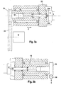
- the centering point arranged on the same spindle in the Z direction Jaws are movable relative to the jaw chuck, or the centering tip relative to the chuck or to the spindle is not decisive, whereby in in practice the displacement of the centering tip 22, 23 in the Z direction compared to the associated jaw chuck and the associated spindle is preferred, such as exemplarily in Fig. 3a, 3b separately for the left and right side of the machine is shown. It is also irrelevant whether there is tension in the jaw chuck on the same In addition, the tension through the centering tip on the same Side is maintained.
- FIG. 1b shows a machine tool that differs from the solution according to FIG. 1a differs in that the tool support 13 with the associated Tool base body 19, which the cutting for the or the tool-based Proceedings are missing.
- FIG. 2a shows the machine according to FIG. 1a from the left side in a section along the line IIa-IIa. It can be seen that the spindle 16 carries Headstock over the tub of a tub-shaped bed 14 in the Z direction movably rests. The one that rotatably supports the tool body 19 Tool support 13, which is designed as an X slide, is in turn in the X direction guided on a Z-slide, with the X-direction directed obliquely downwards at an angle of 60 - 80 ° to the horizontal is inclined.
- the guide plane of the Z slide 27 opposite the bed 14 is also not horizontal or vertically, but at an angle of about 40 - 50 ° opposite inclined to the horizontal.
- Fig. 2b shows a bed construction with a bed 14 ', which with respect the Z direction is symmetrical, that is, on two opposite sides inclined guide surfaces each carries a Z-slide 26 ', 27', the again in each case in the X1 or X2 direction, which strive apart in a V-shape, movable tool support 12 ', 13' with corresponding Wear tool body 18 ', 19'.
- Figures 3a and 3b show the left and right headstock of the machine.
- the respective spindle 15 or 16 is in the headstock, not specified rotatably mounted and axially fixed.
- the jaw chuck 20 or 21 is connected to the spindle and non-rotatably connected to it the jaws 20a, ..., 21a, ...
- Both the spindle 15 and 16 and the jaw chuck 20 and 21 are in Center in the Z direction is hollow throughout, and is in this cavity the centering tip 22 or 23 is mounted, which from the jaw chuck 20 or 21st can also be positioned projecting forward.
- the centering tip is rotatably mounted in relation to the spindle and jaw chuck Axial position shiftable.
- Fig. 3a - as in Figures 1 - is the workpiece, namely the crankshaft 1, with the end flange 6 at the left end, and the end pin 5 at the right end.
- crankshaft 1 is held on the left side by the clamping jaws 20a, 20b, ... of the jaw chuck 20 on the outer circumference of the end flange 6 rest and tension it, the centering tip 22 additionally in the corresponding Centering hole 36 engages.
- the crankshaft On the right is the crankshaft on the other hand, only by means of those engaging in the centering bore 37 Centering tip 23 held corresponding to the associated Bakken 21a, 21b, ... of the jaw chuck 21 protrudes further.
- the Z position of the centering tip 23 is analogous to the other centering tip 22 - by means of a centering stop 35 which can be fixed in the axial position fixed by z.
- the thread between the centering stop 34/35 and the surrounding spindle 15, 16 is self-locking.
- the two spindle sides also differ fundamentally in terms of mutual drives:
- One, for example left, spindle 15 is at high speeds by means of a Motors M drivable, which is mounted on the headstock and for example a belt drive and related pulleys 28, 29, the spindle 15 drives around the Z axis.
- a Motors M drivable which is mounted on the headstock and for example a belt drive and related pulleys 28, 29, the spindle 15 drives around the Z axis.
- the other, e.g. B. right, spindle 16 is by means of another, not shown Motors can be driven slowly by rotating a gear pair by the worm wheel 38 is rotatably connected to the spindle 16 during the Motor, not shown, drives the screw 39.
- This drive train can be uncoupled, for example by disengaging screw 39 and Worm gear 38, or by disengaging a clutch, not shown in this drivetrain.
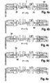
- Figures 4 and 5 show typical clamping situations of the workpiece, for example a crankshaft 1 when processing the different areas of the workpiece.
- the one to be machined End area When machining the end areas of a workpiece, the one to be machined End area preferably held exclusively by means of a centering tip the drive from the other end of the workpiece via the spindle there is done to ensure accessibility for the corresponding tool in the end area to enable at all.
- Figures 4a-4d show situations in which the crankshaft is at the left end by means of the jaws 20a, 20b, ... of the jaw chuck 20 on the circumference of the left end area, so z. B. the end flange 6, clamped and driven in rotation becomes. In the solution according to FIGS. 3a, 3b, this is the one that can be driven quickly Spindle 15.
- the other, right-hand end, the workpiece, must be able to rotate freely be given, as by means of the slow on the right side Rotary drive of the right spindle 16 is a synchronous drive with also high Speed is not possible.
- the other option is the right, that is, the slow spindle drive facing, end of the crankshaft in the jaw chuck there tension, but to decouple the drive train of the right chuck, for example, by disengaging the worm 39 from the worm wheel 38 of the Drive train, as shown in Fig. 4e.
- the workpiece can be subjected to high Speed are driven and thus all the centric machining surfaces on the workpiece by means of a machining process on the workpiece such as Turning, turning rooms or turning-turning rooms can be edited.
- the workpiece must also be in a defined Z position.
- the right centering tip can be used for this purpose the workpiece to the left until the right centering point 23 reaches a centering stop 35 ', for example in the form of that in the figures 3 shown centering stop 35.
- the right to force F2 acting on the left, with which the right centering tip 23 is acted upon be greater than the opposite force F1 with which the left centering tip 22 is applied.
- the force F1 with which the left centering tip 22 is applied is greater than the right-to-left force of the right centering tip 23, 4b, a timely workpiece stop 44 'must be in the region of FIG right spindle 16 to be present.
- the right centering tip must be used at the same time 23 remain axially fixed in the right centering hole 37 of the workpiece, thus the Z position of the right centering tip 23 can be fixed without the rotatability the centering point.
- Fig. 4c differs from the solution according to Fig. 4b in that - at the same Relation of left to right force of the two centering tips - the left one Centering tip, which is subjected to the higher force, against a longitudinal one Centering stop 34 'presses. This must also - as with the solution according to Fig. 4b - happen before the jaws 20a, 20b of the left jaw chuck 20 closed become.
- Fig. 5 shows the drive of the crankshaft from the right side, that is the slow driveline.
- the right end is therefore in FIGS. 5, for example the end pin 5, the crankshaft 1 on the circumference of the jaws 21a, 21b of the right jaw chuck 21, which is from the assigned spindle 16 is driven slowly rotating.
- the left centering tip 22 can engage on the left side Workpiece remain.
- the workpiece can also be left only from the centering tip be held so that the jaws of the chuck are lifted off the workpiece there are.
- Fig. 6 shows the machining of a crank bearing H1 of the crankshaft on the Center bearing ML is tensioned and driven in rotation. It can be seen from this that when the crankshaft rotates around the Z direction, the displacement of the one to be machined Pin bearing pin H1 in the X direction must be compensated by appropriate Tracking the machining tool, for example the rotating tool body 18, to the same extent in the analog direction. From this it is also clear that the diameter of the tool body is large must be chosen enough to be at the most distant position eccentric workpiece surface from the axis of rotation C2 of the tool body still to ensure editing.
- Fig. 6 also shows the inclusion of the end pin 5 between the jaws 21 a, 21b, 21c of the jaw chuck 21, and the fixation of the rotational position of the crankshaft compared to the jaw chuck by a ram 31 off-center and transverse to the Z direction against one of the other pin journals, e.g. B. H3, presses to this to press against a rotary stop 32, rotary stop 32 and Ram 31 are rotatably connected to the chuck or the spindle.
Landscapes
- Engineering & Computer Science (AREA)
- Mechanical Engineering (AREA)
- Turning (AREA)
- Milling Processes (AREA)
- Shafts, Cranks, Connecting Bars, And Related Bearings (AREA)
- Paper (AREA)
- Mechanical Treatment Of Semiconductor (AREA)
- Grinding Of Cylindrical And Plane Surfaces (AREA)
Abstract
Description
Die Erfindung betrifft die Bearbeitung von Werkstücken mittels materialabtragender, vorzugsweise mechanisch materialabtragender, Verfahren und diesbezüglicher Vorrichtungen, wobei die Werkstücke sowohl zentrisch als auch exzentrisch bezüglich der zentrischen Achse des Werkstückes angeordnete, rotationssymmetrische Flächen und ggf. darüber hinausgehend Stirnflächen umfasst, die bearbeitet werden sollen,(siehe z.B. WO-A-95 05265 oder EP-A-0 807 489).The invention relates to the machining of workpieces by means of material-removing, preferably mechanically material-removing process and related Devices, the workpieces being both centric and eccentric arranged rotationally symmetrical with respect to the central axis of the workpiece Surfaces and possibly further front surfaces includes the are to be processed (see e.g. WO-A-95 05265 or EP-A-0 807 489).
Ein typisches derartiges Werkstück sind Kurbelwellen, bei denen die Mantelflächen der Hauptlager die zentrischen rotationssymmetrischen Flächen darstellen und die Mantelflächen der Hublager die exzentrischen rotationssymmetrischen Flächen. Darüber hinaus stellen die Bearbeitungen der zwar zentrischen, jedoch den Endbereich und damit den zum Spannen in Futtern verwendeten Bereich darstellenden Endzapfen bzw. Endflansche (kleiner bzw. großer Außendurchmesser) eine Schwierigkeit dar, und die mit Abnahme großer Materialmengen verbundene Bearbeitung von Wangenseitenflächen.A typical workpiece of this type is crankshafts, in which the lateral surfaces the main bearing represents the centric, rotationally symmetrical surfaces and the lateral surfaces of the pin bearings the eccentric rotationally symmetrical Surfaces. In addition, the machining operations are centric, however the end area and thus the area used for tensioning in chucks End pegs or end flanges (small or large outer diameter) a difficulty, and the associated with the decrease in large quantities of material Machining cheek side surfaces.
Kurbelwellen sind typische Vertreter von Werkstücken, die folgende Probleme in sich vereinen: Crankshafts are typical representatives of workpieces that have the following problems to unite:
Es sind sowohl zentrisch als auch exzentrisch positionierte, rotationssymmetrische Werkstückflächen zu bearbeiten,
- es sind zusätzlich Stimflächen zu bearbeiten,
- es müssen auch die Endbereiche des Werkstückes, an denen normalerweise die Spannung in den Futtern der Maschine erfolgt, bearbeitet werden, und diese müssen in hohem Maße hinsichtlich Rundheit und Mittenfluchtung mit den übrigen Bereichen des Werkstückes übereinstimmen,
- das Werkstück ist aufgrund seiner Geometrie wenig widerstandsfähig gegen vor allem radial aufgebrachte Bearbeitungskräfte.
- additional end faces must be machined,
- the end areas of the workpiece, on which the clamping in the machine chucks normally takes place, must also be machined, and these must correspond to a large extent in terms of roundness and center alignment with the other areas of the workpiece,
- Due to its geometry, the workpiece is not very resistant to radial machining forces.
Zur Bearbeitung der einzelnen Flächen steht die bekannte Palette von materialabtragenden Bearbeitungsverfahren zur Verfügung, beginnend mit den spanabhebenden Bearbeitungsverfahren, deren Werkzeuge über eine geometrisch definierte Schneide verfügen. Diese Verfahren lassen sich in die folgenden zwei Gruppen aufteilen:
- werkstückbasierte Verfahren, also Verfahren, bei denen die gewünschte Schnittgeschwindigkeit (Relativgeschwindigkeit zwischen Werkstückoberfläche und der daran arbeitenden Schneide des Werkzeuges) primär durch die Rotationsgeschwindigkeit des Werkstückes erreicht wird: Längsdrehen, Plandrehen, Räumen, Dreh-Räumen (die Räumschneiden sind auf dem Umfang eines runden Werkzeuggrundkörpers angeordnet, welches sich bei der Bearbeitung dreht, jedoch langsamer als das Werkstück), Dreh-Dreh-Räumen (in Ergänzung zum vorbeschriebenen Drehräumen befinden sich auf dem Werkzeuggrundkörper auch Drehwerkzeuge, bei deren Einsatz das Drehräumwerkzeug nicht rotiert, sondern linear in X- oder Z-Richtung bezüglich des Werkstückes zum Längs- bzw. Plandrehen verfahren wird), Finishen (Schleifen mit im wesentlichen stillstehendem Finish-Werkzeug; noch feinere Körnung als Schleifwerkzeuge) und
- werkzeug-basierte Verfahren, bei denen also die Schnittgeschwindigkeit primär durch die Bewegung, insbesondere Rotation, des Werkzeuges erzielt wird: Orthogonalfräsen (ein Fräswerkzeug, das mit seiner Rotationsachse lotrecht auf der zu bearbeitenden rotationssymmetrischen Fläche steht, bearbeitet diese primär mit den auf der Stirnfläche des Fräsers vorhandenen Stirnschneiden), Außenfräsen (ein scheibenförmiger Fräser, dessen Rotationsachse parallel zur Rotationsachse des Werkstückes liegt, arbeitet primär mit den auf seinem Außenumfang angeordneten Schneiden die entsprechende Mantelfläche des Werkstückes), Außenrundschleifen (anstelle des vorbeschriebenen scheibenförmigen Fräswerkzeuges wird in gleicher Positionierung zum Werkstück eine scheibenförmige Schleifscheibe eingesetzt).
- Workpiece-based processes, i.e. processes in which the desired cutting speed (relative speed between the workpiece surface and the cutting edge of the tool working on it) is primarily achieved by the speed of rotation of the workpiece: longitudinal turning, facing turning, broaching, turning broaching (the broaching blades are on the circumference of a round one Tool base body arranged, which rotates during machining, but slower than the workpiece), turning-broaching (in addition to the above-described turning broaching, there are also turning tools on the tool base body, when using the turning broaching tool does not rotate, but linearly in X or Z direction with respect to the workpiece for longitudinal or face turning), finishing (grinding with essentially stationary finishing tool; even finer grit than grinding tools) and
- Tool-based processes, in which the cutting speed is primarily achieved by the movement, in particular rotation, of the tool: Orthogonal milling (a milling tool that is perpendicular to the rotationally symmetrical surface with its axis of rotation, processes it primarily with that on the end face of the End mill), external milling (a disc-shaped milling cutter, whose axis of rotation is parallel to the axis of rotation of the workpiece, works primarily with the corresponding outer surface of the workpiece with the cutting edges arranged on its outer circumference), external cylindrical grinding (instead of the disk-shaped milling tool described above, one is positioned in the same position as the workpiece disc-shaped grinding wheel used).
Dabei sind die jeweils letztgenannten Vertreter in beiden Gruppen bereits Verfahren mit geometrisch nicht definierter Schneide.The latter representatives in both groups are already procedures with geometrically undefined cutting edge.
Hinzu kommen noch Verfahren, die Material abtragen ohne eine mechanisch wirkende Schneide, beispielsweise Elektroerosionsverfahren, Materialabtrag mittels Laser etc., bei denen jedoch nur geringe Relativgeschwindigkeiten zwischen Werkzeug und Werkstück notwendig sind, und diese Relativgeschwindigkeit wahlweise durch Bewegung des Werkstückes und/oder des Werkzeuges zur Verfügung gestellt werden kann.There are also processes that remove material without a mechanical one Cutting, for example electroerosion processes, material removal by means of Lasers etc., where, however, only low relative speeds between Tool and workpiece are necessary, and this relative speed either by moving the workpiece and / or the tool Can be made available.
Für die Großserienproduktion von derartigen Werkstücken wie etwa PKW-Kurbelwellen sind eine möglichst kurze Bearbeitungszeit - einschließlich Rüst- und Totzeiten - pro Kurbelwelle einerseits sowie niedrige Werkzeug- und Energiekosten andererseits die entscheidenden Paramater, abhängig von den dabei erzielbaren Oberflächenqualitäten (Rundheit, Rauhtiefe etc.), die die Notwendigkeit nachfolgender Endbearbeitungsschritte wie Schleifen und/oder Finishen bedingen können.For the large-scale production of workpieces such as car crankshafts are the shortest possible processing time - including set-up and dead times - per crankshaft on the one hand and low tool and energy costs on the other hand, the decisive parameters, depending on the achievable Surface qualities (roundness, roughness depth, etc.) that the need for subsequent Finishing steps such as grinding and / or finishing may require.
In diesem Sinne sind zur Zeit für die Großserienfertigung nach wie vor die mittels mechanischer Schneide abtragenden Bearbeitungsverfahren zu präferieren. In this sense, the means for mass production are still at the moment to prefer mechanical cutting machining processes.
Dabei steht momentan bezüglich der zentrischen rotationssymmetrischen Flächen die Bearbeitung mittels Drehräumen oder Dreh-Drehräumen im Vordergrund. Hinsichtlich der exzentrischen rotationssymmetrischen Flächen, also beispielsweise den Hublagerstellen, wird derzeit das Außenruridfräsen bevorzugt. Da die Hublagerstelle während der Bearbeitung - damit alle Umfangspunkte von einer Seite aus bearbeitet werden können - um die zentrische Achse des Werkstückes rotiert, ist gleichzeitig eine zeitlich und geometrisch sehr genaue Nachführung des entsprechenden Werkzeuges notwendig. Um dies realisieren zu können, werden für die Bearbeitung dieser exzentrischen rotationssymmetrischen Flächen werkzeug-basierte Verfahren bevorzugt. Bei Einsatz werkstückbasierter Verfahren würde - zur Erzielung einer hohen Schnittgeschwindigkeit und damit einer effizienten Bearbeitung - das Werkstück so schnell rotieren, dass eine Nachführung des Werkzeuges nicht realisierbar wäre, beziehungsweise die so erreichbaren Drehzahlen des Werkstückes und damit Schnittgeschwindigkeiten wären nicht konkurrenzfähig.It currently stands with respect to the centric, rotationally symmetrical surfaces processing by means of turning rooms or turning-turning rooms in the foreground. Regarding the eccentric rotationally symmetrical surfaces, for example the hub bearings, external rutide milling is currently preferred. Because the hub storage during processing - all circumferential points from one side can be machined from - rotated around the central axis of the workpiece, is at the same time a chronologically and geometrically very accurate tracking of the corresponding Tools necessary. To be able to realize this, for the machining of these eccentric rotationally symmetrical surfaces is tool-based Process preferred. When using workpiece-based processes - to achieve a high cutting speed and thus efficient processing - Rotate the workpiece so quickly that the tool is tracked would not be feasible, or the speeds that can be achieved in this way of the workpiece and thus cutting speeds would not be competitive.
Die derzeit bevorzugten Verfahren werden in der Großserienfertigung in der Regel auf getrennten Maschinen nacheinander eingesetzt. Zusätzlich werden - meist ebenfalls auf einer separaten Maschine bzw. Station einer Produktionslinie - vorher die Endbereiche, bei einer KurbeJwelle also Endzapfen und Endflansch, separat wenigstens am Umfang, eventuell auch an den endseitigen Stimfläche, vorbearbeitet, um definierte Spannflächen für die weitere Bearbeitung zur Verfügung zu haben.The currently preferred methods are usually used in large series production used one after the other on separate machines. In addition, usually also on a separate machine or station on a production line - before the end areas, in the case of a crankshaft, i.e. end journal and end flange, separately pre-machined at least on the circumference, possibly also on the end face, to defined clamping surfaces for further processing to have.
Im Sinne der vorliegenden Anmeldung wird bei den zu bearbeitenden Mantelflächen zwar nur von rotationssymmetrischen Flächen gesprochen, da dies der weitaus größte Anteil an Bearbeitungsfällen ist. Selbstverständlich können auch nicht rotationssymmetrische, jedoch konvex gekrümmte Außenrundflächen wie etwa die Nocken von Nockenwellen analog bearbeitet werden.For the purposes of the present application, the lateral surfaces to be machined only spoken of rotationally symmetrical surfaces, since this is the is by far the largest proportion of processing cases. Of course you can too not circularly symmetrical, but convexly curved outer surfaces like For example, the cams of camshafts can be processed analogously.
Gelegentlich wurde auch bereits angedacht, für kleine Stückzahlen, wie etwa Vorserienmodelle von Kurbelwellen etc. die Bearbeitung der zentrischen rotationssymmetrischen Flächen durch werkstück-basierte Bearbeitungsverfahren sowie die Bearbeitung der exzentrischen rotationssymmetrischen Flächen durch werkzeug-basierte Bearbeitungsverfahren auf einer Maschine durchzuführen, indem dort die beiden entsprechenden Werkzeugeinheiten beide vorhanden sind. Dabei stellten die extrem unterschiedlichen zu realisierenden Drehzahlbereiche des Werkstückantriebes das eine Hauptproblem dar, und die Bearbeitung der Endbereiche der Kurbelwelle das andere Hauptproblem.Occasionally, thought has already been given to small quantities, such as pre-series models of crankshafts etc. the processing of the centric rotationally symmetrical Areas through workpiece-based machining processes as well the processing of the eccentric rotationally symmetrical surfaces by tool-based Perform machining operations on a machine by there the two corresponding tool units are both present. there set the extremely different speed ranges of the Workpiece drive is the main problem, and the machining of the end areas the crankshaft the other main problem.
Es ist daher die Aufgabe gemäß der vorliegenden Erfindung, ein Verfahren sowie eine Vorrichtung zu schaffen, bei der Kurbelwellen und ähnliche Teile an den einschlägigen Bearbeitungsstellen (Hublagerstellen, Hauptlagerstellen, Wangenseitenflächen, Endzapfen/Endflansch) auf einer Maschine und damit mit geringem Aufwand an Investitionsgütern und dennoch insgesamt sehr zeiteffizient bearbeitet werden können.It is therefore the object according to the present invention, a method as well to create a device in which crankshafts and similar parts on the relevant Processing points (hub bearings, main bearings, cheek side surfaces, End spigot / end flange) on one machine and thus with a small amount Capital goods expenditure and yet processed overall very efficiently can be.
Diese Aufgabe wird durch die Merkmale der Ansprüche 1 und 7 gelöst. Vorteilhafte
Ausführungsformen ergeben sich aus den Unteransprüchen.This object is solved by the features of
Dabei soll das Werkstück bei allen Bearbeitungsschritten jeweils auf der zentrischen Achse gespannt und um diese Achse drehend angetrieben werden, um den Einsatz mechanisch sehr aufwendiger und teurer sogenannter Taktfutter zu vermeiden, die zusätzlich die Flexibilität einer Maschine stark einschränken, da sie auf die Abmessungen der zu bearbeitenden Kurbelwelle abgestellt sein müssen. The workpiece should be centered on all machining steps Axis tensioned and driven around this axis to the Avoid using mechanically very complex and expensive so-called cycle chucks, which also severely restrict the flexibility of a machine because they must be geared to the dimensions of the crankshaft to be machined.
Durch Einsatz von werkstück-basierten Verfahren für die zentrischen Flächen wird dort bereits eine sehr kurze Bearbeitungszeit bei gleichzeitig sehr guter Oberflächenqualität erreicht.By using workpiece-based processes for the central surfaces there already a very short processing time with very good surface quality reached.
Durch Einsatz der werkzeug-basierten Bearbeitungsverfahren bei exzentrischen Flächen kann die Drehzahl des Werkstückes so niedrig gehalten werden, dass noch eine optimale Nachführung des Werkzeuges und damit eine optimale Maßhaltigkeit dieser Flächen sichergestellt ist.By using the tool-based machining processes for eccentric Surfaces, the speed of the workpiece can be kept so low that optimal tool tracking and thus optimum dimensional accuracy of these areas is ensured.
Um bei den werkstück-basierten Verfahren einerseits und werkzeug-basierten Verfahren andererseits die realisierbaren, maximalen Schnittgeschwindigkeiten erreichen zu können, wird das Werkstück, welches in seinen Endbereichen in Spindeln gelagert und mittels Futter drehend antreibbar ist, von den beiden Seiten her über unterschiedliche Antriebe wahlweise angetrieben, wobei der eine Antrieb die möglichst hohen Drehzahlen für die werkstückbasierten Bearbeitungsverfahren zur Verfügung stellt, die andererseits nur geringe Drehmomente erfordern, während der andere Antrieb zwar nur die geringen notwendigen Werkstückdrehzahlen für werkzeug-basierte Bearbeitungsverfahren aufbringen muss, jedoch bei hohem Drehmoment und Einhaltung definierter Drehlage des Werkstückes, somit auch einer Positioniermöglichkeit der Drehlage des Werkstückes-gegenüber dieser Spindel. Entsprechend ist dieser langsame Antrieb vorzugsweise auch mit einer Selbsthemmung, realisiert mittels z. B. Schnecke/ Schneckenradübersetzung, ausgestattet. Beide Antriebe können von separaten Motoren (bevorzugt) oder einem gemeinsamen Motor aus angetrieben werden, jedoch sollte wenigstens der selbsthemmende langsame Antriebsstrang z. B. zwischen der Spindel und der selbsthemmenden Stelle oder zwischen Futter und Spindel entkuppelbar sein.In order for the workpiece-based processes on the one hand and tool-based On the other hand, process the realizable, maximum cutting speeds to be able to reach the workpiece, which in its end areas in Spindles are mounted and can be rotated by means of chuck from both sides forth driven via different drives, one drive the highest possible speeds for the workpiece-based machining processes provides that, on the other hand, only require low torques, while the other drive only has the low workpiece speeds required for tool-based machining processes, however with high torque and compliance with the defined rotational position of the workpiece, thus also a possibility of positioning the rotational position of the workpiece this spindle. Accordingly, this slow drive is preferably also with a self-locking, realized by means of z. B. worm / worm gear ratio, fitted. Both drives can be operated by separate motors (preferred) or driven by a common motor, however at least the self-locking slow drive train z. B. between the spindle and can be uncoupled from the self-locking point or between the chuck and the spindle his.
Um zusätzlich auch Endzapfen und Endflansch, wenigstens deren Mantelflächen, bearbeiten zu können, müssen die Spindeln neben einem üblichen Spannfutter, etwa einem Dreibacken-Futter, auch eine Zentrierspitze aufweisen, wobei Zentrierspitze und die Backen des Backenfutters relativ zueinander in Axialrichtung (Z-Richtung) verfahrbar sind, beispielsweise durch Verwendung von Füttern mit rückziehbaren Spannbacken. Auf diese Art und Weise ist es möglich, jeweils einen Endbereich drehfest mittels Futterspannung mit der jeweiligen Spindel zu verbinden, während der andere, momentan zu bearbeitende, Endbereich lediglich durch eine Zentrierspitze abgestützt ist.In addition to end journals and end flanges, at least their outer surfaces, To be able to machine, the spindles must be next to a usual chuck, about a three-jaw chuck, also have a centering point, centering point and the jaws of the jaw chuck relative to each other in the axial direction (Z direction) can be moved, for example by using feeds with retractable jaws. In this way it is possible to have one End area rotatably by means of chuck with the respective spindle connect, while the other end area currently being processed is merely is supported by a centering tip.
Der in der langsamen Spindel aufgenommene Endbereich kann dabei - aufgrund Antrieb durch die schnelle Spindel - mit hohen Drehzahlen betrieben werden und damit mit dem auch für die Mittellager verwendeten werkstück-basierten Bearbeitungsverfahren, z. B. Dreh-Drehräumen, bearbeitet werden.The end area recorded in the slow spindle can - due to Drive by the fast spindle - can be operated at high speeds and with the workpiece-based machining process also used for the central bearings, z. B. turn-turn rooms can be edited.
Einschränkungen hinsichtlich der Effizienz sind nur im umgekehrten Fall, also bei Bearbeitung des in der schnellen Spindel aufgenommenen Endbereiches, in der Regel dem Endflansch, notwendig: Dieser ist bei Bearbeitung nur durch eine Zentrierspitze gehalten, während das Werkstück auf der gegenüberliegenden Seite durch das Backenfutter der langsamen Spindel in Drehung versetzt wird.Efficiency restrictions are only in the reverse case, ie Machining of the end area recorded in the fast spindle, in the As a rule, the end flange is necessary: This is only necessary when machining through a centering tip held while the workpiece is on the opposite side is rotated by the jaw chuck of the slow spindle.
Aufgrund der langsamen Drehzahl des Werkstückes stehen realistisch nur zwei Möglichkeiten der Bearbeitung zur Verfügung:Due to the slow speed of the workpiece, there are only two realistically Editing options available:
Entweder Bearbeiten mittels eines der werkstückbasierten Verfahren, wegen niedriger Werkstückdrehzahl jedoch bei sehr niedriger Schnittgeschwindigkeit, mit entsprechender Beschränkung auf hierfür geeignete Schneidstoffe. Beim Drehen ist dies beispielsweise Schnellarbeitsstahl (HSS).Either machining using one of the workpiece-based methods, because of lower Workpiece speed, however, at a very low cutting speed, with the corresponding Restriction to suitable cutting materials. When turning is this is, for example, high-speed steel (HSS).
Da die übrigen, mittels werkzeug-basierter Verfahren bearbeiteten Flächen, beispielsweise die Mittellager, selbst bei Anwendung des Drehens mit Werkzeugen aus Hartmetall, Schneidkeramik und ähnlichen Hochleistungswerkstoffen bearbeitet werden, müssen derartige HSS-Schneiden allein wegen dieser Endflansch-Bearbeitung zusätzlich auf dem entsprechenden Werkzeuggrundkörper vorgesehen werden.Since the other surfaces processed using tool-based processes, for example the center bearings, even when turning with tools machined from hard metal, cutting ceramics and similar high-performance materials such HSS cutters have to be used solely because of this end flange machining additionally provided on the corresponding tool body become.
Schneiden aus Hartmetall oder Schneidkeramik würden bei diesen niedrigen drehzahlen des Werkstückes zu schnell beschädigt werden. Cutting from hard metal or cutting ceramics would be low at these speeds of the workpiece are damaged too quickly.
Die andere Möglichkeit besteht darin, analog der niedrigen Werkstückdrehzahl mit werkzeug-basierten Verfahren, also beispielsweise mittels Außenrundfräsen, diesen Endbereich zu bearbeiten. Nachteil ist dabei die gegenüber werkstückbasierten Verfahren geringfügig schlechtere erzielbare Oberflächenqualität. Da in der Regel für alle gleichartigen Werkstückoberflächen, beispielsweise alle zentrischen Lagerstellen, übereinstimmende Mindestanforderungen hinsichtlich der Oberflächenqualität gestellt werden, wird durch diese Endflanschbearbeitung unter Umständen eine Qualitätsvorgabe nicht erreicht, die für alle anderen Mittellagerstellen aufgrund des geeigneteren Bearbeitungsverfahrens erreichbar ist.The other option is to use the same as the low workpiece speed tool-based processes, for example using external round milling, this Edit end area. The disadvantage is that compared to workpiece-based Process slightly poorer achievable surface quality. There in usually for all similar workpiece surfaces, for example all centric Bearings, matching minimum requirements regarding the Surface quality is provided by this end flange machining Circumstances may not meet a quality target that applies to all other central storage locations is achievable due to the more suitable processing method.
Da bei der Bearbeitung mindestens eines der Endbereiche (Endzapfen/ Endflansch) eine Spannung mittels Futter in der Regel zunächst am unbearbeiteten Außenumfang des Werkstückes notwendig ist, muss wenigstens dieses entsprechende Futter ausgleichende Spannbacken aufweisen. Ebenso muss an einer der Spindeln eine Drehlagenfixierung des Werkstückes gegenüber einer der Spindeln vorhanden sein, beispielsweise ein Drehlagenanschlag oder Richtbacken im entsprechenden Backenfutter.Since at least one of the end areas (end journal / end flange) a tension using chuck is usually first on the unprocessed Outer circumference of the workpiece is necessary, at least this must be appropriate Have chuck balancing jaws. Likewise, one of the Spindles fix the workpiece in rotational position relative to one of the spindles be present, for example a rotational position stop or straightening jaws in the corresponding Jaw chuck.
Da, wie vorbeschrieben, derartige Verfahren und Maschinen primär zur Herstellung von Kurbelwellen oder ähnlichen Werkstücken in geringen Stückzahlen, häufig nur in Einzelstücken, dienen, werden die Außenrundfräser relativ schmal gewählt, so dass sie für alle herzustellenden Kurbelwellen eingesetzt werden können. Entsprechend ist dann jedoch - nach der Bearbeitung eines ersten Axialbereiches an einem Hublager mittels Außenrundfräsen - eine Axialverfahrung des Fräsers - sei es kontinuierlich oder schrittweise - notwendig, bis die gesamte Lagerbreite bearbeitet ist.Since, as described above, such processes and machines are primarily for production of crankshafts or similar workpieces in small numbers, often serve only in individual pieces, the external round milling cutters are chosen to be relatively narrow, so that they can be used for all crankshafts to be manufactured. Correspondingly, however, is then - after machining a first axial area on a pin bearing using external round milling - an axial movement of the Milling cutter - be it continuous or gradual - necessary until the entire width of the warehouse is processed.
Zu diesem Zweck muss zum einen der Fräser in Z-Richtung verfahrbar sein, also der Werkzeugsupport über einen Z-Schlitten verfügen, und zum anderen müssen die Schneiden des Fräsers nicht nur auf dessen Außenumfang, sondern auch im äußeren Randbereich der Stirnfläche vorhanden sein, um bei kontinuierlicher Zustellung in Z-Richtung auch an der Stirnfläche schneiden zu können. Anderenfalls ist nur die axial abschnittweise Bearbeitung über Einstechen und Umfangsbearbeitung möglich.For this purpose, the milling cutter must be able to be moved in the Z direction the tool support have a Z-slide, and the other must the cutting of the milling cutter not only on its outer circumference, but also in outer edge area of the end face to be present with continuous delivery to be able to cut on the end face in the Z direction. Otherwise, is only the axial section machining via grooving and circumferential machining possible.
Sofern ausschließlich die Bearbeitung von Einzelstücken beabsichtigt ist bzw. die Bearbeitungsdauer nur eine sehr untergeordnete Rolle spielt, kann von dem vorbeschriebenen Lösungsgedanken dahingehend abgewichen werden, dass auch die exzentrischen rotationssymmetrischen Flächen und trotz Antriebes während ihrer Bearbeitung über den langsamen Spindelantrieb mit einem werkstückbasierten Bearbeitungsverfahren wie etwa dem Drehen bearbeitet werden. Wie zuvor hinsichtlich der Bearbeitung des im schnellen Spindelfutter aufgenommenen, jedoch nur langsam antreibbaren, Endbereiches beschrieben, erhöht sich dadurch die Bearbeitungszeit für die Hublager und damit der Kurbelwelle insgesamt sehr stark und zusätzlich müssen für diese niedrige Schnittgeschwindigkeit geeignete Schneidstoffe wie etwa HSS-Schneiden vorhanden sein.If only the processing of individual pieces is intended or the Processing time only plays a very subordinate role, can of the above Solution ideas are deviated so that too the eccentric rotationally symmetrical surfaces and despite the drive during processing via the slow spindle drive with a workpiece-based Machining processes such as turning can be processed. How previously regarding the processing of the fast spindle chuck, however, only slowly drivable, described end area increases thereby the processing time for the pin bearings and thus the crankshaft as a whole very strong and additionally need for this low cutting speed suitable cutting materials such as HSS cutting edges are available.
Der Vorteil einer solchen Lösung liegt jedoch maschinentechnisch gesehen darin, dass für Hub- und Hauptlager das gleiche Bearbeitungsverfahren eingesetzt, wenn auch bei stark unterschiedlichen Schnittgeschwindigkeiten, und demzufolge mit der Notwendigkeit unterschiedlicher Schneidstoffe. Diese aus unterschiedlichem Material bestehenden Schneiden können entweder wie vorbeschrieben aus zwei getrennten Werkzeugeinheiten, nämlich z. B. Schneiden aus keramischen Schneidstoffen auf einem Werkzeuggrundkörper und HSS-Schneiden auf dem anderen Werkzeuggrundkörper, angeordnet sein. Beide Werkzeugsysteme benötigen jedoch die gleichen Bewegungsmöglichkeiten (neben Verfahren in der X- und Z-Richtung entweder ein Verschwenken um die C2-Achse oder ein Verfahren in Y-Richtung) und können demzufolge identisch aufgebaut und mit einer identischen Steuerung ausgerüstet sein, was die Kosten senkt.The advantage of such a solution, however, from a machine point of view, is that that the same machining process is used for the lifting and main bearings, albeit at very different cutting speeds, and consequently with the need for different cutting materials. This from different Material existing cutting edges can either be as previously described from two separate tool units, namely z. B. Cutting from ceramic Cutting materials on a basic tool body and HSS cutting edges the other tool body. Both tool systems however, need the same possibilities of movement (in addition to procedures in the X and Z direction either swiveling around the C2 axis or moving in the Y direction) and can therefore be constructed identically and with a identical control, which reduces costs.
Einen Schritt weiter betrachtet könnten - da es sich bei den werkstück-basierten Verfahren ausschließlich um Bearbeitungsverfahren handelt, bei denen das Werkzeug nicht zwingend um volle 360° rotieren muss - Schneiden aus beiden Schneidstoffarten gleichzeitig auf demselben, beispielsweise scheibenförmigen, Werkzeuggrundkörper angeordnet sein, so dass damit insgesamt nur eine einzige Werkzeugeinheit an der Maschine notwendig wäre.Could take a step further - since it is the workpiece-based The procedure is exclusively a processing procedure in which the Tool does not necessarily have to rotate a full 360 ° - cutting from both Types of cutting material simultaneously on the same, for example disc-shaped, Tool base body can be arranged so that only a single total Tool unit on the machine would be necessary.
Unter den vorstehend erwähnten hohen und niedrigen Werkstückdrehzahlen bzw. Schnittgeschwindigkeiten bzw. Drehmomenten beim Antrieb des Werkstückes sind in etwa folgende Wertebereiche zu verstehen:Among the high and low workpiece speeds or Cutting speeds or torques when driving the workpiece the following ranges of values are to be understood:
Hohe Werkstückdrehzahlen von 40 U/min bis 1.600 U/min, insbesondere von 200 U/min bis 800 U/min, niedrige Werkstückdrehzahlen von 0 U/min bis 40 U/min, insbesondere von 20 U/min bis 40 U/min, hohe Drehmomente des Werkstückantriebes von 600 Nm bis 3.000 Nm, insbesondere von 2.000 Nm bis 2.500 Nm, niedrige Drehmomente des Werkstückantriebes von 200 Nm bis 600 Nm, insbesondere von 300 Nm bis 550m, Schnittgeschwindigkeiten von 150 m/s bis 700 mls, insbesondere von 180 m/s bis 250 m/s.High workpiece speeds from 40 rpm to 1,600 rpm, especially from 200 RPM to 800 RPM, low workpiece speeds from 0 RPM to 40 RPM, in particular from 20 rpm to 40 rpm, high torques of the workpiece drive from 600 Nm to 3,000 Nm, in particular from 2,000 Nm to 2,500 Nm, low torques of the workpiece drive from 200 Nm to 600 Nm, in particular from 300 Nm to 550m, cutting speeds from 150 m / s to 700 mls, especially from 180 m / s to 250 m / s.
Ein Detailproblem stellen die bei Kurbelwellen-Lagerstellen häufig notwendigen Hinterschnitte am Rand der Lagerstelle dar, die bei Mittellagerstellen mittels Drehen leicht herzustellen sind, bei einer Bearbeitung der Hublager mittels eines werkzeug-basierten Verfahrens jedoch nicht herstellbar sind. Für diesen Fall müssen nach Bearbeitung der Mantelfläche eines solchen Hublagers die entsprechenden Hinterschnitte mittels Drehen eingebracht werden. Da hierbei die Hublagerstelle exzentrisch um die zentrische Achse des Werkstückes rotiert, muss diese Drehschneide im Umlauf des Werkstückes nachgeführt werden, und aufgrund dessen kann das Werkstück nur mit der niedrigen Drehzahl angetrieben werden. Entsprechend sind auch hier wieder Schneidmittel aus geeigneten Schneidstoffen wie etwa HSS notwendig.A detail problem is posed by those that are often necessary for crankshaft bearings Undercuts at the edge of the bearing point, which at middle bearing points by turning are easy to manufacture when machining the pin bearings using a however, tool-based processes cannot be produced. In this case you have to after machining the outer surface of such a pin bearing, the corresponding Undercuts are made by turning. Since this is the hub storage point rotates eccentrically around the central axis of the workpiece Rotary cutting edge are tracked in the circulation of the workpiece, and due the workpiece can only be driven at the low speed. Accordingly, here again, cutting agents are made of suitable cutting materials such as HSS necessary.
Eine Ausführungsform gemäß der Erfindung ist im folgenden beispielhaft näher beschrieben. Es zeigen
- Fig. 1a:
- eine erfindungsgemäße Maschine in Frontansicht,
- Fig. 1b:
- eine andere erfindungsgemäße Maschine in Frontansicht,
- Fig. 2a:
- die Maschine gemäß Fig. 1a in der Seitenansicht von links,
- Fig. 2b:
- eine andere Bauform der Maschine in Seitenansicht,
- Fig. 3a:
- den linken Spindelbereich der Maschine gemäß Fig. 1a in vergrößertem Teilschnitt,
- Fig. 3b:
- den rechten Spindelbereich der Maschine gemäß Fig. 1a in vergrößertem Teilschnitt,
- Figuren 4:
- Prinzipdarstellungen bei linksseitigem Antrieb des Werkstückes,
- Figuren 5:
- Prinzipdarstellungen bei rechtsseitigem Antrieb des Werkstückes, und
- Fig. 6:
- einen Schnitt entlang der Linie VI-VI der Fig. 1.
- Fig. 1a:
- a machine according to the invention in front view,
- Fig. 1b:
- another machine according to the invention in front view,
- Fig. 2a:
- 1a in side view from the left,
- Fig. 2b:
- another design of the machine in side view,
- Fig. 3a:
- the left spindle area of the machine according to FIG. 1a in an enlarged partial section,
- 3b:
- the right spindle area of the machine according to FIG. 1a in an enlarged partial section,
- Figures 4:
- Principle representations with left-hand drive of the workpiece,
- Figures 5:
- Schematic diagrams for right-hand drive of the workpiece, and
- Fig. 6:
- a section along the line VI-VI of Fig. 1st
Fig. 1a zeigt eine Werkzeugmaschine, die ein Werkstück, beispielsweise die dargestellte
Kurbelwelle 1, welche sowohl zentrische Flächen 2, z. B. Hauptlagerstellen,
als auch exzentrische Flächen 3, beispielsweise Hublagerstellen, umfaßt,
an den Endbereichen drehend antreibbar aufnimmt und bearbeitet.Fig. 1a shows a machine tool that a workpiece, such as the one shown
Dabei sind die axialen Endbereich des Werkstückes in den Aufnahmevorrichtungen
zweier gegeneinander gerichteter, miteinander fluchtender Spindeln
15, 16 aufgenommen. Als Aufnahmeeinrichtungen dienen sowohl Backenfutter 20
bzw. 21 als auch Zentrierspitzen 22, 23, die an jeder der Spindeln 15, 16 angeordnet
sind. The axial end region of the workpiece is in the holding devices
two mutually aligned, aligned
Die Spindeln 15, 16 sind auf dem Bett 14 der Maschine angeordnet, ebenso wie
die Werkzeugsupporte 12, 13, die jeweils eine Werkzeugeinheit tragen, welche
um eine parallel zur Rotationsachse (Z-Achse) des Werkstückes parallele Achse
(C2-Achse) drehend antreibbar ist.The
Zusätzlich sind die Werkzeugsupporte 12, 13 in X-Richtung, also quer zur axialen
Z-Richtung, definiert verfahrbar auf den jeweiligen, in Z-Richtung verfahrbaren, Z-Schlitten
26, 27. Die Z-Schlitten sind entlang der Z-Führungen 33 verfahrbar. Die
Werkzeugeinheiten sind in der Regel scheibenförmige Werkzeuggrundkörper,
wobei der Werkzeuggrundkörper 18 des einen Werkzeugsupportes 12 im äußeren
Umfangsbereich mit Schneiden besetzt ist, die für ein werkstück-basiertes Verfahren
einsetzbar sind, beispielsweise mit Drehschneiden oder Dreh-Drehräumschneiden.In addition, the tool supports 12, 13 are in the X direction, that is to say transversely to the axial
Z direction, defined to be movable on the respective Z slide that can be moved in the
Entsprechend muß sich dieser Werkzeuggrundkörper 18 nicht unbedingt über
volle 360° definiert verdrehen lassen, sondern es ist bereits das Verschwenken
um geringere Winkelbereiche um die C2-Achse ausreichend. Die Einnahme einer
definierten Drehlage des Werkzeuggrundkörpers 18 ist jedoch notwendig. Entsprechend
ist dieser Werkzeuggrundkörper 18 bei der Bearbeitung einer zentrischen
rotationssymmetrischen Fläche 2, nämlich einem Mittellager, dargestellt.Accordingly, this
Im Gegensatz dazu ist der andere Werkzeuggrundkörper 19 mit Schneiden eines
werkzeug-basierten Verfahrens, beispielsweise mit Frässchneiden, in seinem äußeren
Umfangsbereich bestückt, die dementsprechend vorzugsweise über den
gesamten Umfang des scheibenförmigen Grundkörpers 19 verteilt, insbesondere
gleichmäßig verteilt, sind. Der Werkzeuggrundkörper 19 dieses werkzeug-basierten
Verfahrens muß dementsprechend über mehr als 360°, insbesondere
über eine beliebige Anzahl von Umdrehungen, drehend antreibbar sein.In contrast, the other
Die Z-Führungen 33 sind so lang ausgebildet, daß beide Werkzeuggrundkörper
18, 19 jede Axialposition am Werkstück in Z-Richtung erreichen können, insbesondere
auch die Endbereiche, nämlich den in Fig. 1a am rechten Ende der Kurbelwelle
dargestellten Endzapfen 5 sowie den am linken Ende der Kurbelwelle 1
dargestellten Endflansch 6, der einen größeren Außendurchmesser als der Endzapfen
5 aufweist.The Z-
Wie insbesondere die vergrößerte Detaildarstellung des linken Aufnahmebereiches
der Fig. 1a zeigt, ist die Kurbelwelle während der Bearbeitung vorzugsweise
an beiden Enden in den jeweiligen Backenfuttern 20, 21, also mit Hilfe radial
greifender Spannbacken 20a, 20b, ..., 21a, 21b, ... gehalten und drehend angetrieben.Like in particular the enlarged detail of the left recording area
1a shows, the crankshaft is preferred during machining
at both ends in the respective jaw chucks 20, 21, ie with the help of radial
Nur wenn die für das Ansetzen der Spannbacken notwendigen Umfangsbereiche
sowie die stirnseitigen Endflächen der Kurbelwelle bearbeitet werden, wird auf der
jeweiligen Seite die Spannung mittels Spannbacken gelöst, und die Kurbelwelle
auf dieser Seite ausschließlich mittels einer Zentrierspitze 22, 23 in einer entsprechenden
Zentrierbohrung der Kurbelwelle gehalten. Gleichzeitig sind die Spannbacken
auf dieser Seite in Z-Richtung gegenüber der Zentrierspitze axial zurückgezogen,
damit das betreffende Werkzeug an der Endfläche z. B. 5a oder der
Umfangsfläche des Endflansches bzw. Endzapfens arbeiten kann.Only if the circumferential areas necessary for the application of the clamping jaws
as well as the end faces of the crankshaft are machined on the
each side released the tension using jaws, and the crankshaft
on this side only by means of a centering
Dabei ist vorzugsweise der gesamte Spindelstock, in dem eine der Spindeln, z. B.
die Spindel 16, gelagert ist, in Z-Richtung gegenüber dem Bett 14 der Maschine
definiert verfahrbar. Dies ermöglicht die Bearbeitung unterschiedlich langer Werkstücke,
und erleichtert auch die Be- und Entladung der Maschine mit Werkstücken.
Ob bei der axialen Relativbewegung der Backen eines Backenfutters gegenüber
der an derselben Spindel angeordneten Zentrierspitze in Z-Richtung die
Spannbacken gegenüber dem Backenfutter beweglich sind, oder die Zentrierspitze
relativ zum Spannfutter bzw. zur Spindel, ist nicht entscheidend, wobei in
der Praxis die Verlagerung der Zentrierspitze 22, 23 in Z-Richtung gegenüber dem
zugeordneten Backenfutter und der zugeordneten Spindel bevorzugt wird, wie
beispielhaft in Fig. 3a, 3b getrennt für die linke und rechte Seite der Maschine
dargestellt ist. Unerheblich ist ferner, ob bei Spannung im Backenfutter auf derselben
Seite zusätzlich die Spannung durch die Zentrierspitze auf der gleichen
Seite aufrechterhalten bleibt. The entire headstock, in which one of the spindles, for. B.
the
Fig. 1b zeigt eine Werkzeugmaschine, die sich von der Lösung gemäß Fig. 1a
dadurch unterscheidet, daß der Werkzeugsupport 13 mit dem zugeordneten
Werkzeuggrundkörper 19, welcher die Schneiden für das oder die werkzeug-basierten
Verfahren trägt, fehlt.FIG. 1b shows a machine tool that differs from the solution according to FIG. 1a
differs in that the
Fig. 2a zeigt die Maschine gemäß Fig. 1a von der linken Seite her in einem Schnitt
entlang der Linie IIa-IIa. Dabei ist zu erkennen, daß der die Spindel 16 tragende
Spindelstock über der Wanne eines wannenförmigen Bettes 14 in Z-Richtung
verfahrbar ruht. Der den Werkzeuggrundkörper 19 drehend antreibbar tragende
Werkzeugsupport 13, der als X-Schlitten ausgebildet ist, ist seinerseits in X-Richtung
verfahrbar auf einem Z-Schlitten geführt, wobei die X-Richtung dabei
schräg abwärts gerichtet unter einem Winkel von 60 - 80° gegenüber der Horizontalen
geneigt ist.FIG. 2a shows the machine according to FIG. 1a from the left side in a section
along the line IIa-IIa. It can be seen that the
Auch die Führungsebene des Z-Schlittens 27 gegenüber dem Bett 14 ist nicht horizontal
oder vertikal, sondern unter einem Winkel von etwa 40 - 50° gegenüber
der Horizontalen geneigt.The guide plane of the
Fig. 2b zeigt dagegen eine Bettkonstruktion mit einem Bett 14', welches bezüglich der Z-Richtung symmetrisch ausgebildet ist, also auf zwei gegenüberliegend schräg angeordneten Führungsflächen jeweils einen Z-Schlitten 26', 27' trägt, die jeweils wiederum einen in X1- bzw. X2-Richtung, welche V-förmig nach oben auseinanderstreben, verfahrbaren Werkzeugsupport 12', 13' mit entsprechenden Werkzeuggrundkörpem 18', 19' tragen.Fig. 2b, on the other hand, shows a bed construction with a bed 14 ', which with respect the Z direction is symmetrical, that is, on two opposite sides inclined guide surfaces each carries a Z-slide 26 ', 27', the again in each case in the X1 or X2 direction, which strive apart in a V-shape, movable tool support 12 ', 13' with corresponding Wear tool body 18 ', 19'.
Die Figuren 3a und 3b zeigen den linken und rechten Spindelstock der Maschine.Figures 3a and 3b show the left and right headstock of the machine.
Dabei ist die jeweilige Spindel 15 bzw. 16 im nicht näher bezeichneten Spindelstock
drehbar gelagert und axial fest positioniert. Auf dem vorderen Ende der
Spindel und drehfest mit dieser verbunden sitzt das Backenfutter 20 bzw. 21 mit
den Spannbacken 20a, ..., 21a, ... The
Sowohl die Spindel 15 bzw. 16 als auch das Backenfutter 20 bzw. 21 sind im
Zentrum in Z-Richtung durchgängig hohl ausgebildet, und in diesem Hohlraum ist
die Zentrierspitze 22 bzw. 23 gelagert, die aus dem Backenfutter 20 bzw. 21
ebenfalls nach vorne vorstehend positioniert werden kann.Both the
Die Zentrierspitze ist gegenüber Spindel und Backenfutter drehbar gelagert und in Axialposition verlagerbar.The centering tip is rotatably mounted in relation to the spindle and jaw chuck Axial position shiftable.
Wie anhand der Figuren 4 und 5 noch zu erläutern sein wird, ist für die Bearbeitung
unter Umständen eine Fixierbarkeit der Z-Position der Zentrierspitze 22, 23
trotz freier Drehbarkeit um die Z-Achse notwendig. In den Lösungen gemäß Fig.
3a, 3b ist dies gelöst mittels eines im Inneren der Spindel 15 in Z-Richtung verfahrbaren,
insbesondere gegenüber dem Innendurchmesser der Spindel 15 mittels
eines Gewindes verschraubbaren Zentrier-Anschlages 34 bzw. 35 gelöst, der
über einen Hinterschnitt mit dem hinteren Ende der Zentrierspitze 22, 23 verbunden
ist und damit die Zentrierspitze sowohl schieben als auch ziehen kann. Dabei
muß eine relative Drehbarkeit zwischen der Zentrierspitze 22, 23 und dem Zentrieranschlag
34, 35 gegeben sein.As will be explained with reference to FIGS. 4 and 5, is for processing
possibly the Z position of the centering
In Fig. 3a ist - ebenso wie in den Figuren 1 - das Werkstück, nämlich die Kurbelwelle
1, mit dem Endflansch 6 am linken Ende dargestellt, und dem Endzapfen 5
am rechten Ende.In Fig. 3a - as in Figures 1 - is the workpiece, namely the
Dabei ist die Kurbelwelle 1 auf der linken Seite gehalten, indem dort die Spannbacken
20a, 20b, ... des Backenfutters 20 am Außenumfang des Endflansches 6
anliegen und diesen spannen, wobei die Zentrierspitze 22 zusätzlich in der entsprechenden
Zentrierbohrung 36 eingreift. Auf der rechten Seite ist die Kurbelwelle
dagegen ausschließlich mittels der in die Zentrierbohrung 37 eingreifenden
Zentrierspitze 23 gehalten, die entsprechend gegenüber den zugeordneten Bakken
21a, 21b, ... des Backenfutters 21 weiter vorsteht.The
Auch hier ist die Z-Position der Zentrierspitze 23 - analog zur anderen Zentrierspitze
22 - mittels eines in der Axialposition fixierbaren Zentrier-Anschlages 35
fixiert, indem z. B. das Gewinde zwischen dem Zentrieranschlag 34/35 und der
umgebenden Spindel 15, 16 selbsthemmend ausgebildet ist.Here, too, the Z position of the centering
Die beiden Spindelseiten unterscheiden sich ferner grundlegend hinsichtlich der wechselseitigen Antriebe:The two spindle sides also differ fundamentally in terms of mutual drives:
Die eine, beispielsweise linke, Spindel 15 ist mit hohen Drehzahlen mittels eines
Motors M antreibbar, der am Spindelstock montiert ist und beispielsweise über
einen Riemenantrieb und diesbezügliche Riemenscheiben 28, 29 die Spindel 15
drehend um die Z-Achse antreibt.One, for example left,
Die andere, z. B. rechte, Spindel 16 ist dagegen mittels eines weiteren, nicht dargestellten
Motors über eine Zahnradpaarung langsam drehend antreibbar, indem
das Schneckenrad 38 drehfest mit der Spindel 16 verbunden ist, während der
nicht dargestellte Motor die Schnecke 39 antreibt. Dieser Antriebsstrang ist entkuppelbar,
beispielsweise durch Außereingriffbringen von Schnecke 39 und
Schneckenrad 38, oder mittels Auskuppeln einer nicht dargestellten Kupplung in
diesem Antriebsstrang.The other, e.g. B. right,
Die Figuren 4 und 5 zeigen typische Spannsituationen des Werkstückes, beispielsweise
einer Kurbelwelle 1, bei Bearbeitung der unterschiedlichen Bereiche
des Werkstückes.Figures 4 and 5 show typical clamping situations of the workpiece, for example
a
Da die erfindungsgemäße Maschine/Verfahren nicht auf möglichst hohe Bearbeitungseffizienz,
sondern auf vollständige Bearbeitung von zentrischen, exzentrischen
und Stirnflächen auf derselben Maschine ausgelegt ist, sollen z. B. bei
Kurbelwellen vorzugsweise auch die Endbereiche der Kurbelwelle mit bearbeitet
werden, um eine Vorbearbeitung - ausgenommen das Einbringen von Zentrierbohrungen
für die Zentrierspitzen - weitestgehend zu vermeiden. In diesem Fall
werden bevorzugt die Umfangsflächen des Endflansches 6 und der Endzapfen 5,
auf denen die Spannbacken der Backenfutter angreifen sollen, als erstes bearbeitet,
und - falls notwendig und gewünscht - auch die jeweilige stirnseitige Endfläche
5a bzw. 6a. Since the machine / method according to the invention is not based on the highest possible machining efficiency,
but on complete machining of centric, eccentric
and end faces is designed on the same machine, z. B. at
Crankshafts preferably also machined the end regions of the crankshaft
to a preprocessing - except for the introduction of center holes
for the centering tips - to be avoided as far as possible. In this case
the peripheral surfaces of the
Bei der Bearbeitung der Endbereiche eines Werkstückes wird der zu bearbeitende Endbereich vorzugsweise ausschließlich mittels Zentrierspitze gehalten, während der Antrieb von dem anderen Ende des Werkstückes her über die dortige Spindel erfolgt, um die Zugänglichkeit für das entsprechende Werkzeug im Endbereich überhaupt zu ermöglichen.When machining the end areas of a workpiece, the one to be machined End area preferably held exclusively by means of a centering tip the drive from the other end of the workpiece via the spindle there is done to ensure accessibility for the corresponding tool in the end area to enable at all.
Die Figuren 4a - 4d zeigen Situationen, bei denen die Kurbelwelle am linken Ende
mittels der Backen 20a, 20b, ... des Backenfutters 20 am Umfang des linken Endbereiches,
also z. B. des dortigen Endflansches 6, geklemmt und drehend angetrieben
wird. Bei der Lösung gemäß Fig. 3a, 3b sei dies die schnell antreibbare
Spindel 15.Figures 4a-4d show situations in which the crankshaft is at the left end
by means of the
Dabei muß die freie Drehbarkeit des anderen, rechten Endes, des Werkstückes
gegeben sein, da mittels des auf der rechten Seite vorhandenen langsamen
Drehantriebes der rechten Spindel 16 ein synchroner Antrieb mit ebenfalls hoher
Drehzahl nicht möglich ist.The other, right-hand end, the workpiece, must be able to rotate freely
be given, as by means of the slow on the right side
Rotary drive of the
Dies wird erreicht, indem - wie in den Figuren 4a - 4d dargestellt - das rechte Ende
des Werkstückes gehalten wird, indem nur die rechte Zentrierspitze 23 in der entsprechenden
rechten Zentrierbohrung 37 des Werkstückes sitzt, und die rechte
Zentrierspindel 23 gegenüber der rechten Werkstückspindel 16 und dem rechten
Antriebsstrang frei drehbar ist.This is achieved by - as shown in Figures 4a - 4d - the right end
of the workpiece is held by only the
Die andere Möglichkeit besteht darin, das rechte, also dem langsamen Spindelantrieb
zugewandte, Ende der Kurbelwelle zwar im dortigen Backenfutter zu
spannen, dem Antriebsstrang des rechten Spannfutters jedoch zu entkoppeln,
beispielsweise durch Ausrücken der Schnecke 39 aus dem Schneckenrad 38 des
Antriebsstranges, wie in Fig. 4e dargestellt.The other option is the right, that is, the slow spindle drive
facing, end of the crankshaft in the jaw chuck there
tension, but to decouple the drive train of the right chuck,
for example, by disengaging the
Durch die Spannungen gemäß der Figuren 4 kann das Werkstück mit hoher
Drehzahl angetrieben werden und damit am Werkstück alle zentrischen Bearbeitungsflächen
mittels eines werkstückseitigen Bearbeitungsverfahrens wie etwa
Drehen, Drehräumen oder Dreh-Drehräumen, bearbeitet werden. Darunter fallen
auch der auf der rechten Seite angeordnete Endzapfen 5 und dessen Endfläche
5a, die bis nahe bis an die im Eingriff befindliche rechte Zentrierspitze 23 heran
bearbeitet werden kann.Due to the tensions according to FIG. 4, the workpiece can be subjected to high
Speed are driven and thus all the centric machining surfaces on the workpiece
by means of a machining process on the workpiece such as
Turning, turning rooms or turning-turning rooms can be edited. This includes
also the end pin 5 arranged on the right side and its
Dabei muß sich das Werkstück auch in einer definierten Z-Position befinden.The workpiece must also be in a defined Z position.
Gemäß Fig. 4a kann zu diesem Zweck die rechte Zentrierspitze zusammen mit
dem Werkstück soweit nach links geschoben werden, bis die rechte Zentrierspitze
23 einen Zentrier-Anschlag 35' erreicht, beispielsweise in Form des in den Figuren
3 dargestellten Zentrieranschlages 35. In diesem Fall muß die von rechts nach
links wirkende Kraft F2, mit welcher die rechte Zentrierspitze 23 beaufschlagt wird,
größer sein als die entgegengerichtete Kraft F1, mit der die linke Zentrierspitze 22
beaufschlagt wird.According to FIG. 4a, the right centering tip can be used for this purpose
the workpiece to the left until the
Gleiches gilt auch im Fall der Fig. 4d, wobei dort jedoch im Bereich des linken Spannfutters ein Werkstückanschlag 45' vorhanden ist, durch den das Werkstück mit der linken Endfläche 6a gegen diesen Werkstückanschlag 45' gedrückt wird.The same applies in the case of FIG. 4d, but there in the area of the left Chuck a workpiece stop 45 'is present through which the workpiece is pressed against this workpiece stop 45 'with the left end face 6a.
Ist dagegen die Kraft F1, mit der die linke Zentrierspitze 22 beaufschlagt wird,
größer als die von rechts nach links wirkende Kraft der rechten Zentrierspitze 23,
so muß gemäß Fig. 4b ein rechtzeitiger Werkstückanschlag 44' im Bereich der
rechten Spindel 16 vorhanden sein. Dabei muß gleichzeitig die rechte Zentrierspitze
23 axial fest in der rechten Zentrierbohrung 37 des Werkstückes verbleiben,
also die Z-Position der rechten Zentrierspitze 23 fixierbar sein, ohne die Drehbarkeit
der Zentrierspitze zu behindern.If, on the other hand, the force F1 with which the
Fig. 4c unterscheidet sich von der Lösung gemäß Fig. 4b dadurch, daß - bei gleicher
Relation von linker zu rechter Kraft der beiden Zentrierspitzen - die linke
Zentrierspitze, die mit der höheren Kraft beaufschlagt ist, gegen einen längsseitigen
Zentrieranschlag 34' drückt. Auch dies muß - wie bei der Lösung gemäß
Fig. 4b - geschehen, bevor die Backen 20a, 20b des linken Backenfutters 20 geschlossen
werden. Fig. 4c differs from the solution according to Fig. 4b in that - at the same
Relation of left to right force of the two centering tips - the left one
Centering tip, which is subjected to the higher force, against a longitudinal one
Centering stop 34 'presses. This must also - as with the solution according to
Fig. 4b - happen before the
Fig. 5 zeigt dagegen den Antrieb der Kurbelwelle von der rechten Seite, also über
den langsamen Antriebsstrang. Daher ist in den Figuren 5 das rechte Ende, beispielsweise
der Endzapfen 5, der Kurbelwelle 1 am Umfang von den Backen 21a,
21b des rechten Backenfutters 21 gespannt, welches von der zugeordneten Spindel
16 langsam drehend antreibbar ist.Fig. 5 shows the drive of the crankshaft from the right side, that is
the slow driveline. The right end is therefore in FIGS. 5, for example
the end pin 5, the
Bei dieser Antriebsart werden die exzentrischen Flächen, Mantelflächen ebenso
wie Stirnflächen, des Werkstückes bearbeitet mittels eines werkzeug-basierten
Verfahrens, wobei das Werkzeug in X-Richtung nachgeführt werden muß, wie
anhand der Fig. 6 zu erläutern. Dabei ist das gegenüberliegende linke Ende des
Werkstückes - gemäß Fig. 5a und 5b - ebenfalls zwischen den Backen 20a, 20b,
... des dortigen Backenfutters 20 aufgenommen, da der auf der linken Seite vorhandene
Antriebsstrang nicht selbsthemmend ist und vom rechten Antriebsstrang
aus unter Vermittlung des Werkstückes leer durchdrehend mit angetrieben wird.
Dies führt keineswegs zu einer unerwünschten Torsion des Werkstückes, sondern
der mit dem Werkstück verbundene linksseitige, leer mitlaufende, Antriebsstrang
dient vielmehr der dynamischen Dämpfung des Werkstückes während der Bearbeitung.
Dies ist vorteilhaft, da die hier zum Einsatz kommenden werkzeugbasierten
Verfahren wie etwa das fräsen wegen des unterbrochenen Schnittes eine
stärkere dynamische Belastung auf das Werkstück bringen als die werkzeug-basierten
Verfahren.With this type of drive, the eccentric surfaces, lateral surfaces as well
like end faces, the workpiece is machined using a tool-based
Procedure, the tool must be tracked in the X direction, such as
to explain with reference to FIG. 6. The opposite left end of the
Workpiece - according to FIGS. 5a and 5b - also between the
Zusätzlich kann auf der linken Seite die linke Zentrierspitze 22 im Eingriff am
Werkstück bleiben.In addition, the left centering
Auch die Aufnahme der linken Seite des Werkstückes ausschließlich mittels der
linksseitigen Zentrierspitze 22 ist möglich.Also the recording of the left side of the workpiece only by means of the
left-
Um auch hier das Werkstück in einer definierten Z-Position zu halten, kann entweder
(Fig. 5a) die rechte Zentrierspitze 23 gegen einen rechtsseitigen Zentrieranschlag
35' gefahren werden, wobei dann - analog zur Fig. 4a - die mittels der
rechten Zentrierspitze von rechts nach links in das Werkstück einwirkende Kraft
F2 größer als die entgegengesetzt wirkende Kraft der linken Zentrierspitze F1
bzw. des linken Futters sein muß.To keep the workpiece in a defined Z position here, either
(Fig. 5a) the
Die andere Möglichkeit besteht gemäß Fig. 5b darin, die von links nach rechts
mittels der linken Zentrierspitze 22 bzw. des linken Backenfutters 20 in Z-Richtung
auf die Kurbelwelle wirkende Kraft F1 größer zu wählen als die entgegengerichtete
Kraft F2 und das Werkstück dadurch gegen einen rechtsseitigen Werkstückanschlag
44' zu drücken.The other possibility according to FIG. 5b is that from left to right
by means of the left centering
Dabei kann - gemäß Fig. 5c - das Werkstück links auch nur von der Zentrierspitze gehalten sein, so daß die Backen des Futters dort von dem Werkstück abgehoben sind.According to FIG. 5c, the workpiece can also be left only from the centering tip be held so that the jaws of the chuck are lifted off the workpiece there are.
Fig. 6 zeigt die Bearbeitung eines Hublagers H1 der Kurbelwelle, die auf dem
Mittellager ML gespannt und drehend angetrieben wird. Daraus ist ersichtlich, daß
bei Drehung der Kurbelwelle um die Z-Richtung die Verlagerung des zu bearbeitenden
Hublagerzapfens H1 in X-Richtung ausgeglichen werden muß durch entsprechende
Nachführung des bearbeitenden Werkzeuges, beispielsweise des
rotierenden Werkzeuggrundkörpers 18, im gleichen Maß in analoger Richtung.
Daraus wird ferner klar, daß der Durchmesser der Werkzeuggrundkörper groß
genug gewählt sein muß, um bei der am weitesten entfernten Position einer solchen
exzentrischen Werkstückfläche von der Rotationsachse C2 des Werkzeuggrundkörpers
noch eine Bearbeitung sicherzustellen.Fig. 6 shows the machining of a crank bearing H1 of the crankshaft on the
Center bearing ML is tensioned and driven in rotation. It can be seen from this that
when the crankshaft rotates around the Z direction, the displacement of the one to be machined
Pin bearing pin H1 in the X direction must be compensated by appropriate
Tracking the machining tool, for example the
Fig. 6 zeigt ferner die Aufnahme des Endzapfens 5 zwischen den Backen 21 a,
21b, 21c des Backenfutters 21, sowie die Fixierung der Drehlage der Kurbelwelle
gegenüber dem Backenfutter, indem ein Stößel 31 außermittig und quer zur Z-Richtung
gegen einen der anderen Hublagerzapfen, z. B. H3, drückt, um diesen
gegen einen Drehlagenanschlag 32 zu drücken, wobei Drehlagenanschlag 32 und
Stößel 31 mit dem Futter bzw. der Spindel drehfest verbunden sind. Fig. 6 also shows the inclusion of the end pin 5 between the
- 11
- Kurbelwellecrankshaft
- 22
- zentrische Flächecentric surface
- 33
- exzentrische Flächeeccentric area
- 44
- WangenflächeWangen area
- 55
- Endzapfenend journal
- 5a5a
- Endflächeend face
- 66
- Endflanschend flange
- 6a6a
- Endflächeend face
- 77
- Hublagerpin bearings
- 88th
- Hauptlagermain bearing
- 1010
- Z-Richtung (Axialrichtung)Z direction (axial direction)
- 1111
- Maschinemachine
- 1212
- Werkzeug-SupportTool Support
- 1313
- Werkzeug-SupportTool Support
- 1414
- Bettbed
- 1515
- Spindelnspindles
- 1616
- Spindelnspindles
- 1717
- Motorengine
- 1818
- Werkzeug-GrundkörperBasic tool body
- 1919
- Werkzeug-GrundkörperBasic tool body
- 2020
- Backen-FutterJaw chuck
- 20a, 20b20a, 20b
- Backejaw
- 2121
- Backejaw
- 2222
- Zentrierspitzecentering
- 2323
- Zentrierspitzecentering
- 2424
- Längsanschlaglongitudinal stop
- 2525
- Längsanschlaglongitudinal stop
- 2626
- Z-SchlittenZ slide
- 2727
- Z-SchlittenZ slide
- 2828
- Riemenscheibepulley
- 2929
- Riemenscheibepulley
- 3030
- Endstücktail
- 3131
- Stößeltappet
- 3232
- Drehlagen-AnschlagRotational positions stop
- 3333
- Z-FührungenZ guide
- 3434
- Zentrier-AnschlagCentering stop
- 3535
- Zentrier-AnschlagCentering stop
- 3636
- Zentrierbohrungcentering
- 3737
- Zentrierbohrungcentering
- 3838
- Schneckenradworm
- 3939
- Schneckeslug
- 44'44 '
- Werkstück-AnschlagWorkpiece stop
- 45'45 '
- Werkstück-AnschlagWorkpiece stop
Claims (14)
- A method of machining both the concentric (2) and also the eccentric, rotationally symmetrical surfaces (3) of workpieces, in particular crankshafts (1), by mechanical material removal in one and the same machine (11),
whereincharacterized in thatthe workpiece is clamped and drivable in rotation in all machining steps on the central axis,the concentric rotationally symmetrical surfaces (2) are machined by workpiece-based methods, andwhen machining the eccentric rotationally symmetrical surfaces (3) the machining operation is effected by tool-based methods,
the workpiece is drivable from one end at high speeds of rotation for machining by means of workpiece-based methods and from the other end at low speeds of rotation and maintaining defined rotational positions for machining by means of tool-based methods. - A method as set forth in claim 1 characterized in that the eccentric rotationally symmetrical workpiece surfaces (3) are machined by means of workpiece-based methods but at speeds of workpiece rotation which are lower by at least a factor of 10 than when using tool-based methods.
- A method as set forth in one of the preceding claims characterized in that the end journals of the workpiece are also machined, and especially when machining the end portions the one end portion is machined at a high speed of rotation of the workpiece and by means of a workpiece-based method and the other end portion is machined at a speed of workpiece rotation lower by at least a factor of 10 by means of a drive from the end of the workpiece drivable at a low speed of rotation.
- A method as set forth in one of the preceding claims characterized in that the one end portion is an end journal and the other end portion is an end flange of an outside diameter substantially larger than the end journal, in particular in the case of a crankshaft (1) as a workpiece, and the workpiece is drivable at a high speed of rotation from the side, in particular the end flange (6), and/or especially the machining of the end portions is effected as early as possible, in particular prior to the other concentric rotationally symmetrical surfaces, and from machining of the end portions the peripheral surface of at least one of the end portions is used for clamping and/or driving purposes, in particular by means of jaw-type chucks.
- A method as set forth in one of the preceding claims characterized in that the eccentric rotationally symmetrical surfaces (3), in particular the big-end bearings (7) of a crankshaft (1), are machined prior to the concentric rotationally symmetrical surfaces (2) - except the end regions - , in particular the main bearings (8) of a crankshaft (1), and/or especially the high speeds of rotation of the workpiece during the machining operation are speeds of rotation of between 40 rpm and 1600 rpm, in particular between 200 rpm and 800 rpm, and low speeds of rotation of the workpiece are between 0 rpm and 40 rpm, in particular between 20 rpm and 40 rpm.
- A method as set forth in one of the preceding claims characterized in that the high drive torque for the workpiece during the machining operation is drive torques of between 600 N x m and 3000 N x m, in particular between 2000 N x m and 2500 N x m and the low drive torque for the workpiece is drive torques of between 200 N x m and 600 N x m, in particular 300 N x m and 550 N x m, and/or especially that the cutting speeds are in the range of between 150 m/s and 700 m/s, in particular between 180 m/s and 250 m/s.
- A machine (11) for machining both the concentric (2) and also the eccentric, rotationally symmetrical surfaces (3) of workpieces, in particular crankshafts (1), by mechanical material removal, comprisingcharacterized in thata bed (14),two oppositely directed, rotationally drivable spindles (15, 16) for receiving and driving the ends of the workpiece, in particular a crankshaft (1), about the longitudinal direction (10), the Z-axis, andat least one tool support (12, 13) which is definedly displaceable at least in the X-direction,the one spindle (15) is drivable at a high speed of rotation and the other spindle (16) is drivable at a low speed of rotation and is capable of moving to defined rotational positions (C'-axis), andat least one of the spindles (15, 16) has a rotational position-directing device for the workpiece.
- A machine as set forth in claim 7 characterized in that the tool support (12, 13), in addition to displaceability in the X-direction, has either displaceability in the Y-direction or the possibility of pivotal movement about the Z-direction (C2-axis), and/or especially that the rotational drive for the slower spindle (16) is a self-locking rotational drive and in particular has a worm/worm gear pairing.
- A machine as set forth in one of the preceding apparatus claims characterized in that the machine (2) has tool supports (12, 13) of which one carries a tool for workpiece-based machining methods, in particular a turning tool, a broaching tool, a rotational broaching tool, a turning-rotational broaching tool or a finishing tool, and the other carries at least one tool for a tool-based machining method, in particular an orthogonal milling cutter or an externally toothed milling cutter.
- A machine as set forth in one of the preceding apparatus claims characterized in that the drives of the spindles (15, 16) are uncoupleable, and/or especially that the spindles (15, 16) are driven from the same motor (17).
- A machine as set forth in one of the preceding apparatus claims characterized in that the tools are arranged on at least one disk-shaped main tool body (18, 19) at the external periphery and in particular the tools for tool-based methods are arranged distributed over the entire periphery of the main body (18, 19).
- A machine as set forth in one of the preceding apparatus claims characterized in that the machine is provided with tools of different materials, in particular materials which are intended for high cutting speeds, in particular above 180 m/s on the one hand and low cutting speeds, in particular a maximum of 180 m/s on the other hand, in particular with hard metal or carbide metal or ceramic cutting materials and high-speed steel (HSS), that is to say steel tools, on the other hand, and/or especially that the machine has only a single tool support (12) on which are arranged tools for high cutting speeds and tools for low cutting speeds, which however are all tools for workpiece-based machining methods.
- A machine as set forth in one of the preceding apparatus claims characterized in that at least one of the spindles, in particular both spindles (15, 16), have on the one hand a chuck for clamping at the external periphery, in particular a jaw chuck (20) and (21) respectively, and on the other hand a centering point (22) and (23) respectively, in particular a centering point which is movable relative to the chuck in the Z-direction, and/or especially that the centering point (22, 23) is free-runningly rotatably supported.
- A machine as set forth in one of the preceding apparatus claims characterized in that the centering point (22, 23) can be axially fixed in a defined Z-position with respect to the jaw chuck, and/or especially that at least one and in particular both spindles (15, 16) has a longitudinal abutment (24) or (25) respectively either for the Z-position of the centering point (22, 23) with respect to the jaw chuck (20, 21) or with respect to the spindle (15, 16) or a longitudinal abutment for the workpiece with respect to the jaw chuck (20, 21), and/or especially that the axial forces to which the centering points (22, 23) can be subjected are adjustable, in particular in respect of whether the respective axial force is greater or smaller than the axial force acting on the other centering point, for example (23).
Applications Claiming Priority (3)
| Application Number | Priority Date | Filing Date | Title |
|---|---|---|---|
| DE10052443A DE10052443A1 (en) | 2000-10-23 | 2000-10-23 | Combination machine |
| DE10052443 | 2000-10-23 | ||
| PCT/EP2001/012247 WO2002034466A1 (en) | 2000-10-23 | 2001-10-23 | Multi-purpose machine |
Publications (2)
| Publication Number | Publication Date |
|---|---|
| EP1330338A1 EP1330338A1 (en) | 2003-07-30 |
| EP1330338B1 true EP1330338B1 (en) | 2004-09-15 |
Family
ID=7660711
Family Applications (1)
| Application Number | Title | Priority Date | Filing Date |
|---|---|---|---|
| EP01978451A Revoked EP1330338B1 (en) | 2000-10-23 | 2001-10-23 | Multi-purpose machine |
Country Status (6)
| Country | Link |
|---|---|
| US (1) | US6926591B2 (en) |
| EP (1) | EP1330338B1 (en) |
| JP (1) | JP2004512185A (en) |
| AT (1) | ATE276070T1 (en) |
| DE (2) | DE10052443A1 (en) |
| WO (1) | WO2002034466A1 (en) |
Families Citing this family (20)
| Publication number | Priority date | Publication date | Assignee | Title |
|---|---|---|---|---|
| DE10245071B4 (en) * | 2002-09-27 | 2006-08-24 | Niles-Simmons Industrieanlagen Gmbh | Machine for roughing and finishing the journals of crankshafts |
| JP4065185B2 (en) * | 2002-11-26 | 2008-03-19 | 武蔵精密工業株式会社 | Method and apparatus for grinding non-circular rotating workpiece |
| US7917646B2 (en) * | 2002-12-19 | 2011-03-29 | Intel Corporation | Speculative distributed conflict resolution for a cache coherency protocol |
| US20050262250A1 (en) * | 2004-04-27 | 2005-11-24 | Batson Brannon J | Messaging protocol |
| US20050240734A1 (en) * | 2004-04-27 | 2005-10-27 | Batson Brannon J | Cache coherence protocol |
| US7822929B2 (en) * | 2004-04-27 | 2010-10-26 | Intel Corporation | Two-hop cache coherency protocol |
| US7791593B2 (en) * | 2005-03-18 | 2010-09-07 | The Invention Science Fund I, Llc | Machine-differentiatable identifiers having a commonly accepted meaning |
| DE102006014972B4 (en) * | 2005-12-20 | 2018-06-21 | Gebr. Heller Maschinenfabrik Gmbh | Combined machining method and machining device |
| DE102008007175B4 (en) | 2008-02-01 | 2010-06-02 | Erwin Junker Maschinenfabrik Gmbh | Method for grinding the main and stroke bearings of a crankshaft by external cylindrical grinding and apparatus for carrying out the method |
| DE102009021803B4 (en) * | 2009-05-18 | 2012-07-12 | Emag Holding Gmbh | Method and device for machining crankshafts |
| DE102011113757B4 (en) * | 2011-09-18 | 2020-12-31 | Mag Ias Gmbh | Method and device for finishing workpieces |
| JP5916121B2 (en) * | 2012-06-28 | 2016-05-11 | コマツNtc株式会社 | Shaft-shaped workpiece processing equipment |
| EP2965845B1 (en) | 2013-02-01 | 2017-11-29 | Gildemeister Drehmaschinen GmbH | Tool turret |
| US9321140B2 (en) | 2013-08-01 | 2016-04-26 | Ford Global Technologies, Llc | System for machine grinding a crankshaft |
| JP2015083329A (en) * | 2013-10-25 | 2015-04-30 | 住友重機械工業株式会社 | Method for manufacturing eccentric oscillation type speed reducer |
| DE102014204807B4 (en) * | 2014-03-14 | 2016-12-15 | Erwin Junker Grinding Technology A.S. | Method and device for grinding large crankshafts |
| CN108637277B (en) * | 2018-07-15 | 2023-06-30 | 赖旭亮 | Surface high-precision turning process of curved workpiece and its processing equipment |
| CN111618665B (en) * | 2020-05-19 | 2022-03-29 | 南方科技大学 | High-efficiency low-damage processing method and processing device |
| CN112238370B (en) * | 2020-09-07 | 2022-05-27 | 湖北坚丰科技股份有限公司 | Cutter device and method for improving machining precision of slender shaft |
| CN112476068A (en) * | 2020-11-26 | 2021-03-12 | 杭州佳顿智能科技有限公司 | Manufacturing and processing technology of engine camshaft |
Family Cites Families (13)
| Publication number | Priority date | Publication date | Assignee | Title |
|---|---|---|---|---|
| GB674065A (en) | 1948-06-10 | 1952-06-18 | Robert Musyl | Improvements in or relating to machines for grinding the main bearing pins and crank pins of crankshafts |
| NL6410508A (en) | 1964-09-09 | 1966-03-10 | ||
| US4018724A (en) | 1975-11-18 | 1977-04-19 | The General Tire & Rubber Company | Flame retardant flexible urethane foams |
| JPS531368A (en) | 1976-06-28 | 1978-01-09 | Nippon Kayaku Kk | Method and system for removing foreign matters in water |
| JPS54296A (en) * | 1977-06-02 | 1979-01-05 | Komatsu Ltd | Method of grinding crank shaft |
| JPS5494192A (en) * | 1978-01-10 | 1979-07-25 | Ishikawajima Harima Heavy Ind Co Ltd | Crank shaft grinding device |
| DE4327807C2 (en) | 1993-08-18 | 1995-06-14 | Erwin Junker | Method and grinding machine for grinding a crankshaft |
| JPH0961190A (en) | 1995-08-24 | 1997-03-07 | Mitsubishi Heavy Ind Ltd | Measuring apparatus using thin film sensor |
| DE69626101T2 (en) | 1995-11-30 | 2003-11-20 | Nippei Toyama Corp., Tokio/Tokyo | DEVICE AND METHOD FOR PHASE INDEXING A CRANKSHAFT |
| JPH10249686A (en) * | 1997-03-14 | 1998-09-22 | Nippei Toyama Corp | Cylindrical grinding machine and crankshaft grinding method |
| DE19749939C2 (en) * | 1997-11-11 | 2003-10-23 | Boehringer Werkzeugmaschinen | Process for machining workpieces |
| JP2000107901A (en) * | 1998-09-29 | 2000-04-18 | Toyoda Mach Works Ltd | Machining method for crankshaft |
| JP3787248B2 (en) * | 1999-09-30 | 2006-06-21 | 株式会社ジェイテクト | Method and apparatus for controlling sizing of machine tool |
-
2000
- 2000-10-23 DE DE10052443A patent/DE10052443A1/en not_active Withdrawn
-
2001
- 2001-10-23 WO PCT/EP2001/012247 patent/WO2002034466A1/en not_active Ceased
- 2001-10-23 US US10/381,584 patent/US6926591B2/en not_active Expired - Fee Related
- 2001-10-23 DE DE50103668T patent/DE50103668D1/en not_active Expired - Fee Related
- 2001-10-23 EP EP01978451A patent/EP1330338B1/en not_active Revoked
- 2001-10-23 JP JP2002537495A patent/JP2004512185A/en active Pending
- 2001-10-23 AT AT01978451T patent/ATE276070T1/en not_active IP Right Cessation
Also Published As
| Publication number | Publication date |
|---|---|
| US6926591B2 (en) | 2005-08-09 |
| DE10052443A1 (en) | 2002-05-08 |
| ATE276070T1 (en) | 2004-10-15 |
| WO2002034466A1 (en) | 2002-05-02 |
| EP1330338A1 (en) | 2003-07-30 |
| US20040023600A1 (en) | 2004-02-05 |
| DE50103668D1 (en) | 2004-10-21 |
| JP2004512185A (en) | 2004-04-22 |
Similar Documents
| Publication | Publication Date | Title |
|---|---|---|
| EP1330338B1 (en) | Multi-purpose machine | |
| EP0334298B1 (en) | Method and device for machining articles having a rotational symmetry | |
| DE19749939C2 (en) | Process for machining workpieces | |
| EP1526946B1 (en) | Method and system for grinding a rotationally symmetric machine part comprising a longitudinal borehole | |
| EP0720883B1 (en) | Method and device for working pieces with eccentric mainly rotation symmetric surfaces | |
| EP0968069B1 (en) | Machine tool | |
| DE102011113758B4 (en) | Method and device for finishing workpieces | |
| DE102011113757B4 (en) | Method and device for finishing workpieces | |
| DE2338207C3 (en) | Multi-spindle automatic lathe | |
| EP3412395A2 (en) | Device and method for chamfering an internally cogged workpiece | |
| EP0868242B1 (en) | Rotary milling process and device | |
| DE2918723A1 (en) | REVOLVER HEAD FOR A LATHE | |
| DE10245071B4 (en) | Machine for roughing and finishing the journals of crankshafts | |
| EP0379723A2 (en) | Groove machining lathe equipped with tools | |
| DE3333243A1 (en) | Multi-spindle automatic lathe | |
| DE4022572A1 (en) | LATHE WITH DOUBLE REVOLVER | |
| EP0119236B1 (en) | Automatic multi-spindle lathe | |
| DE3000055A1 (en) | Cylindrical workpiece shaping machine - has horizontal rotary cylinder with radially adjusted end cutters controlled by axial rack and pinion drive | |
| DE69935647T2 (en) | SIMPLIFIED ROTATION SYMMETRIC WORKPIECES MACHINING MACHINE, ESPECIALLY CRANKSHAFTS AND WORKING PROCESSES SUCH AS A MACHINE | |
| DE102021123380B3 (en) | Device and method for machining rotating workpieces | |
| EP3790702B1 (en) | Ball track milling machine having a rotary holder with at least two rotational positioning devices | |
| EP1761712B1 (en) | Method for producing turning workpieces concentrically arrangeable in each other | |
| DE2321862C3 (en) | Lathe for non-circular machining of the control cams of camshafts |
Legal Events
| Date | Code | Title | Description |
|---|---|---|---|
| PUAI | Public reference made under article 153(3) epc to a published international application that has entered the european phase |
Free format text: ORIGINAL CODE: 0009012 |
|
| 17P | Request for examination filed |
Effective date: 20030523 |
|
| AK | Designated contracting states |
Designated state(s): AT BE CH CY DE DK ES FI FR GB GR IE IT LI LU MC NL PT SE TR |
|
| GRAP | Despatch of communication of intention to grant a patent |
Free format text: ORIGINAL CODE: EPIDOSNIGR1 |
|
| GRAS | Grant fee paid |
Free format text: ORIGINAL CODE: EPIDOSNIGR3 |
|
| GRAA | (expected) grant |
Free format text: ORIGINAL CODE: 0009210 |
|
| AK | Designated contracting states |
Kind code of ref document: B1 Designated state(s): AT DE ES FR GB IT |
|
| PG25 | Lapsed in a contracting state [announced via postgrant information from national office to epo] |
Ref country code: IT Free format text: LAPSE BECAUSE OF FAILURE TO SUBMIT A TRANSLATION OF THE DESCRIPTION OR TO PAY THE FEE WITHIN THE PRESCRIBED TIME-LIMIT;WARNING: LAPSES OF ITALIAN PATENTS WITH EFFECTIVE DATE BEFORE 2007 MAY HAVE OCCURRED AT ANY TIME BEFORE 2007. THE CORRECT EFFECTIVE DATE MAY BE DIFFERENT FROM THE ONE RECORDED. Effective date: 20040915 Ref country code: GB Free format text: LAPSE BECAUSE OF FAILURE TO SUBMIT A TRANSLATION OF THE DESCRIPTION OR TO PAY THE FEE WITHIN THE PRESCRIBED TIME-LIMIT Effective date: 20040915 Ref country code: FR Free format text: LAPSE BECAUSE OF FAILURE TO SUBMIT A TRANSLATION OF THE DESCRIPTION OR TO PAY THE FEE WITHIN THE PRESCRIBED TIME-LIMIT Effective date: 20040915 |
|
| REG | Reference to a national code |
Ref country code: GB Ref legal event code: FG4D Free format text: NOT ENGLISH |
|
| REF | Corresponds to: |
Ref document number: 50103668 Country of ref document: DE Date of ref document: 20041021 Kind code of ref document: P |
|
| PG25 | Lapsed in a contracting state [announced via postgrant information from national office to epo] |
Ref country code: AT Free format text: LAPSE BECAUSE OF NON-PAYMENT OF DUE FEES Effective date: 20041023 |
|
| PG25 | Lapsed in a contracting state [announced via postgrant information from national office to epo] |
Ref country code: ES Free format text: LAPSE BECAUSE OF FAILURE TO SUBMIT A TRANSLATION OF THE DESCRIPTION OR TO PAY THE FEE WITHIN THE PRESCRIBED TIME-LIMIT Effective date: 20041226 |
|
| GBV | Gb: ep patent (uk) treated as always having been void in accordance with gb section 77(7)/1977 [no translation filed] |
Effective date: 20040915 |
|
| PLAQ | Examination of admissibility of opposition: information related to despatch of communication + time limit deleted |
Free format text: ORIGINAL CODE: EPIDOSDOPE2 |
|
| PLBQ | Unpublished change to opponent data |
Free format text: ORIGINAL CODE: EPIDOS OPPO |
|
| PLBI | Opposition filed |
Free format text: ORIGINAL CODE: 0009260 |
|
| PLAQ | Examination of admissibility of opposition: information related to despatch of communication + time limit deleted |
Free format text: ORIGINAL CODE: EPIDOSDOPE2 |
|
| PLAR | Examination of admissibility of opposition: information related to receipt of reply deleted |
Free format text: ORIGINAL CODE: EPIDOSDOPE4 |
|
| PLBQ | Unpublished change to opponent data |
Free format text: ORIGINAL CODE: EPIDOS OPPO |
|
| PLAB | Opposition data, opponent's data or that of the opponent's representative modified |
Free format text: ORIGINAL CODE: 0009299OPPO |
|
| PLAX | Notice of opposition and request to file observation + time limit sent |
Free format text: ORIGINAL CODE: EPIDOSNOBS2 |
|
| 26 | Opposition filed |
Opponent name: HEGENSCHEIDT-MFD GMBH & CO.KG Effective date: 20050615 Opponent name: GEBR. HELLERMASCHINENFABRIK GMBH Effective date: 20050614 |
|
| R26 | Opposition filed (corrected) |
Opponent name: HEGENSCHEIDT-MFD GMBH & CO.KG Effective date: 20050615 Opponent name: GEBR. HELLERMASCHINENFABRIK GMBH Effective date: 20050614 |
|
| EN | Fr: translation not filed | ||
| PGFP | Annual fee paid to national office [announced via postgrant information from national office to epo] |
Ref country code: DE Payment date: 20051031 Year of fee payment: 5 |
|
| PLAF | Information modified related to communication of a notice of opposition and request to file observations + time limit |
Free format text: ORIGINAL CODE: EPIDOSCOBS2 |
|
| PLBB | Reply of patent proprietor to notice(s) of opposition received |
Free format text: ORIGINAL CODE: EPIDOSNOBS3 |
|
| PG25 | Lapsed in a contracting state [announced via postgrant information from national office to epo] |
Ref country code: DE Free format text: LAPSE BECAUSE OF NON-PAYMENT OF DUE FEES Effective date: 20070501 |
|
| RDAF | Communication despatched that patent is revoked |
Free format text: ORIGINAL CODE: EPIDOSNREV1 |
|
| RDAG | Patent revoked |
Free format text: ORIGINAL CODE: 0009271 |
|
| STAA | Information on the status of an ep patent application or granted ep patent |
Free format text: STATUS: PATENT REVOKED |
|
| 27W | Patent revoked |
Effective date: 20090727 |