EP1314897A2 - Bolzendübel mit Spreizkontrolle - Google Patents
Bolzendübel mit Spreizkontrolle Download PDFInfo
- Publication number
- EP1314897A2 EP1314897A2 EP02405972A EP02405972A EP1314897A2 EP 1314897 A2 EP1314897 A2 EP 1314897A2 EP 02405972 A EP02405972 A EP 02405972A EP 02405972 A EP02405972 A EP 02405972A EP 1314897 A2 EP1314897 A2 EP 1314897A2
- Authority
- EP
- European Patent Office
- Prior art keywords
- bolt
- recess
- dowel according
- face
- setting direction
- Prior art date
- Legal status (The legal status is an assumption and is not a legal conclusion. Google has not performed a legal analysis and makes no representation as to the accuracy of the status listed.)
- Granted
Links
Images
Classifications
-
- F—MECHANICAL ENGINEERING; LIGHTING; HEATING; WEAPONS; BLASTING
- F16—ENGINEERING ELEMENTS AND UNITS; GENERAL MEASURES FOR PRODUCING AND MAINTAINING EFFECTIVE FUNCTIONING OF MACHINES OR INSTALLATIONS; THERMAL INSULATION IN GENERAL
- F16B—DEVICES FOR FASTENING OR SECURING CONSTRUCTIONAL ELEMENTS OR MACHINE PARTS TOGETHER, e.g. NAILS, BOLTS, CIRCLIPS, CLAMPS, CLIPS OR WEDGES; JOINTS OR JOINTING
- F16B13/00—Dowels or other devices fastened in walls or the like by inserting them in holes made therein for that purpose
- F16B13/04—Dowels or other devices fastened in walls or the like by inserting them in holes made therein for that purpose with parts gripping in the hole or behind the reverse side of the wall after inserting from the front
- F16B13/08—Dowels or other devices fastened in walls or the like by inserting them in holes made therein for that purpose with parts gripping in the hole or behind the reverse side of the wall after inserting from the front with separate or non-separate gripping parts moved into their final position in relation to the body of the device without further manual operation
- F16B13/0858—Dowels or other devices fastened in walls or the like by inserting them in holes made therein for that purpose with parts gripping in the hole or behind the reverse side of the wall after inserting from the front with separate or non-separate gripping parts moved into their final position in relation to the body of the device without further manual operation with an expansible sleeve or dowel body driven against a tapered or spherical expander plug
-
- F—MECHANICAL ENGINEERING; LIGHTING; HEATING; WEAPONS; BLASTING
- F16—ENGINEERING ELEMENTS AND UNITS; GENERAL MEASURES FOR PRODUCING AND MAINTAINING EFFECTIVE FUNCTIONING OF MACHINES OR INSTALLATIONS; THERMAL INSULATION IN GENERAL
- F16B—DEVICES FOR FASTENING OR SECURING CONSTRUCTIONAL ELEMENTS OR MACHINE PARTS TOGETHER, e.g. NAILS, BOLTS, CIRCLIPS, CLAMPS, CLIPS OR WEDGES; JOINTS OR JOINTING
- F16B13/00—Dowels or other devices fastened in walls or the like by inserting them in holes made therein for that purpose
- F16B13/04—Dowels or other devices fastened in walls or the like by inserting them in holes made therein for that purpose with parts gripping in the hole or behind the reverse side of the wall after inserting from the front
- F16B13/06—Dowels or other devices fastened in walls or the like by inserting them in holes made therein for that purpose with parts gripping in the hole or behind the reverse side of the wall after inserting from the front combined with expanding sleeve
- F16B13/063—Dowels or other devices fastened in walls or the like by inserting them in holes made therein for that purpose with parts gripping in the hole or behind the reverse side of the wall after inserting from the front combined with expanding sleeve by the use of an expander
- F16B13/065—Dowels or other devices fastened in walls or the like by inserting them in holes made therein for that purpose with parts gripping in the hole or behind the reverse side of the wall after inserting from the front combined with expanding sleeve by the use of an expander fastened by extracting the screw, nail or the like
-
- F—MECHANICAL ENGINEERING; LIGHTING; HEATING; WEAPONS; BLASTING
- F16—ENGINEERING ELEMENTS AND UNITS; GENERAL MEASURES FOR PRODUCING AND MAINTAINING EFFECTIVE FUNCTIONING OF MACHINES OR INSTALLATIONS; THERMAL INSULATION IN GENERAL
- F16B—DEVICES FOR FASTENING OR SECURING CONSTRUCTIONAL ELEMENTS OR MACHINE PARTS TOGETHER, e.g. NAILS, BOLTS, CIRCLIPS, CLAMPS, CLIPS OR WEDGES; JOINTS OR JOINTING
- F16B31/00—Screwed connections specially modified in view of tensile load; Break-bolts
- F16B31/02—Screwed connections specially modified in view of tensile load; Break-bolts for indicating the attainment of a particular tensile load or limiting tensile load
-
- F—MECHANICAL ENGINEERING; LIGHTING; HEATING; WEAPONS; BLASTING
- F16—ENGINEERING ELEMENTS AND UNITS; GENERAL MEASURES FOR PRODUCING AND MAINTAINING EFFECTIVE FUNCTIONING OF MACHINES OR INSTALLATIONS; THERMAL INSULATION IN GENERAL
- F16B—DEVICES FOR FASTENING OR SECURING CONSTRUCTIONAL ELEMENTS OR MACHINE PARTS TOGETHER, e.g. NAILS, BOLTS, CIRCLIPS, CLAMPS, CLIPS OR WEDGES; JOINTS OR JOINTING
- F16B2200/00—Constructional details of connections not covered for in other groups of this subclass
- F16B2200/95—Constructional details of connections not covered for in other groups of this subclass with markings, colours, indicators or the like
Definitions
- the invention relates to a bolt plug with a bolt that has an external thread at one end and at the opposite end a widening in the setting direction Has expansion head and an expansion sleeve that can be expanded by the expansion head.
- Bolt dowels of the type mentioned above are used to fasten objects to one Underground.
- a borehole is made in the subsurface, the diameter of which is approximately corresponds to the outside diameter of the bolt or even compared to it Has undersize.
- the bolt dowel is, for example, by one or more blows with a hammer, placed in the borehole.
- the bolt plug is only under high force, e.g. hammer blows, to be brought into the borehole.
- high force e.g. hammer blows
- the present invention has for its object an economically producible To design bolt anchors in such a way that their appearance means that they are in the set state Draw conclusions about the quality of the fastening.
- the object is achieved in that the bolt on the setting direction side facing end face has at least one peripheral depression with a depth.
- the depression is advantageously open towards the outer circumference of the bolt, to ensure deformation of the face of the bolt. It also prevents the Outer circumference of the bolt open recess an excessive expansion of the outer circumference of the bolt due to the material displaced during insertion. Furthermore, one further execution of the recess in the area of the outer circumference a web with a small Wall thickness to ensure a closed outer circumference.
- the depression in the radial projection preferably has an approximately triangular cross section to ensure economical production of the bolt dowel.
- the depression advantageously forms on the end face facing away from the setting direction side of the bolt has a rectangular opening in order to produce the bolt anchor economically to ensure.
- the depression forms on the a trapezoidal opening facing away from the direction of insertion of the bolt.
- the depression advantageously has at least a distance a from the central axis of the Bolt that corresponds to 0.15 to 0.35 times the diameter of the bolt ensure an optimal load bearing of the bolt.
- the depth of the depression preferably corresponds to 0.03 to 0.08 times the diameter of the bolt to ensure economical production of the recess. Furthermore this ensures that, on the one hand, no impairment of the load height of the Bolt dowel occurs and on the other hand, the depressions, for example by a User or a setting control machine used, easily detectable.
- the maximum extending in the circumferential direction of the bolt corresponds Width of the recess 0.05 to 0.2 times the diameter of the bolt to the To optimally dimension the deformation of the depression when driving into the borehole.
- there are four depressions evenly distributed over the circumference of the bolt provided to be independent of the direction of the driving process on the setting direction side facing away from the impulse acting a clearly visible deformation sure.
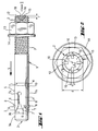
- 1 and 2 is a bolt dowel according to the invention with a bolt 1 which is attached to one End an external thread 2 and at the opposite end one, in the setting direction S widening, expanding head 3 and with an expandable by the expanding head 3, Expanding sleeve 4, shown, the bolt dowel also having a nut 13, which can be screwed onto the external thread 2. Usually closes in the setting direction S to the nut 13 on a washer 14.
- the spreading head 3 has a substantially cylindrical section 3 a on which on the side facing away from the setting direction, a conical section widening in setting direction S. 3b connects.
- the expansion sleeve 4 has four longitudinal slots 6 distributed uniformly over its circumference 5, which are designed to be open in the setting direction S and the end region of the setting direction Divide the expansion sleeve 4 into four expansion tabs 7.
- the Spreading tabs 7 each partially extend into the radial projection of the cone section 3b.
- each spreading flap 7 has an on the outer contour 8, to the longitudinal slots 6 embossment 9 arranged approximately in the center.
- the bolt 1 has a taper in the area in question 10, the depth of which corresponds approximately to the wall thickness of the expansion sleeve 4.
- the circular, The wall 11 facing away from the setting direction forms a stop for the expansion sleeve 4.
- the bolt 1 has four evenly on the end 15 facing away from the setting direction side distributed over the circumference, peripheral recesses 16 with a depth t1 that the Corresponds to 0.025 times the diameter d of the bolt.
- the triangular in the radial projection trained, depressions 16 are to the chamfered outer periphery 12 of the bolt 1, or external thread 2 openly formed and form on the setting direction side facing end face 15 of the bolt 1 is a basically rectangular Opening 18.
- Each two corresponding depressions 16 lie diametrically opposite one another.
- the depressions are at a distance a from the central axis 17 of the bolt 1 which corresponds to 0.3 times the diameter d of the bolt.
- the maximum width e of the depressions 16 extending in the circumferential direction of the bolt 1 0.025 times the diameter d of the bolt 1.
Landscapes
- Engineering & Computer Science (AREA)
- General Engineering & Computer Science (AREA)
- Mechanical Engineering (AREA)
- Dowels (AREA)
- Bolts, Nuts, And Washers (AREA)
Abstract
Description
- Fig. 1
- Eine Seitenansicht eines erfindungsgemässen Bolzendübels;
- Fig. 2
- eine vergrösserte Darstellung der Aufsicht auf die setzrichtungsseitig abgewandte Stirnseite des in Fig. 1 dargestellten Bolzendübels, gesehen in Richtung II auf Fig. 1.
Claims (9)
- Bolzendübel mit einem Bolzen (1), der an einem Ende ein Aussengewinde (2) und am gegenüberliegenden Ende einen, sich in Setzrichtung (S) erweiternden, Spreizkopf (3) aufweist und eine, durch den Spreizkopf (3) aufweitbare, Spreizhülse (4), dadurch gekennzeichnet, dass der Bolzen (1) an der setzrichtungsseitig abgewandten Stirnseite (15) zumindest eine periphere Vertiefung (16) mit einer Tiefe (t1) aufweist.
- Bolzendübel nach Anspruch 1, dadurch gekennzeichnet, dass die Vertiefung (16) zum Aussenumfang des Bolzens (1) hin offen ausgebildet ist
- Bolzendübel nach Anspruch 1 oder 2, dadurch gekennzeichnet, dass die Vertiefung (16) in der Radialprojektion einen etwa dreiecksförmigen Querschnitt aufweist.
- Bolzendübel nach einem der Ansprüche 1 bis 3, dadurch gekennzeichnet, dass die Vertiefung (16) auf der setzrichtungsseitig abgewandten Stirnseite (15) des Bolzens (1) eine rechteck-förmige Öffnung (18) bildet.
- Bolzendübel nach einem der Ansprüche 1 bis 4, dadurch gekennzeichnet, dass jeweils zwei korrespondierende Vertiefungen (16, 18) einander diametral gegenüberliegen.
- Bolzendübel nach einem der Ansprüche 1 bis 5, dadurch gekennzeichnet, dass die Vertiefung (16) zumindest einen Abstand (a) von der Mittelachse (17) des Bolzens (1) aufweist, der dem 0,15- bis 0,35-fachen des Durchmessers (d) des Bolzens (1) entspricht.
- Bolzendübel nach einem der Ansprüche 1 bis 6, dadurch gekennzeichnet, dass die Tiefe (t1) der Vertiefung (16) dem 0,03- bis 0,08-fachen des Durchmessers (d) des Bolzens (1) entspricht.
- Bolzendübel nach einem der Ansprüche 1 bis 7, dadurch gekennzeichnet, dass die sich in Umfangsrichtung des Bolzens (1) erstreckende maximale Breite (e) der Vertiefung (16) dem 0,05- bis 0,2-fachen des Durchmessers (d) des Bolzens (1) entspricht.
- Bolzendübel nach einem der Ansprüche 1 bis 8, dadurch gekennzeichnet, dass vier gleichmässig über den Umfang der Stirnseite (15) des Bolzens (1) verteilte Vertiefungen (16, 18) vorgesehen sind.
Applications Claiming Priority (3)
| Application Number | Priority Date | Filing Date | Title |
|---|---|---|---|
| DE10157586A DE10157586A1 (de) | 2001-11-23 | 2001-11-23 | Bolzendübel mit Spreizkontrolle |
| DE10157586 | 2001-11-23 | ||
| CA002411334A CA2411334C (en) | 2001-11-23 | 2002-11-06 | Dowel bolt with expansion control |
Publications (3)
| Publication Number | Publication Date |
|---|---|
| EP1314897A2 true EP1314897A2 (de) | 2003-05-28 |
| EP1314897A3 EP1314897A3 (de) | 2003-12-10 |
| EP1314897B1 EP1314897B1 (de) | 2005-06-29 |
Family
ID=32963068
Family Applications (1)
| Application Number | Title | Priority Date | Filing Date |
|---|---|---|---|
| EP02405972A Expired - Lifetime EP1314897B1 (de) | 2001-11-23 | 2002-11-12 | Bolzendübel mit Spreizkontrolle |
Country Status (8)
| Country | Link |
|---|---|
| US (1) | US6827535B2 (de) |
| EP (1) | EP1314897B1 (de) |
| JP (1) | JP4065394B2 (de) |
| CN (1) | CN1287097C (de) |
| AT (1) | ATE298844T1 (de) |
| CA (1) | CA2411334C (de) |
| DE (2) | DE10157586A1 (de) |
| ES (1) | ES2243682T3 (de) |
Cited By (3)
| Publication number | Priority date | Publication date | Assignee | Title |
|---|---|---|---|---|
| US7744320B2 (en) | 2006-06-05 | 2010-06-29 | Illinois Tool Works Inc. | Anchor bolt and annularly grooved expansion sleeve assembly exhibiting high pull-out resistance, particularly under cracked concrete test conditions |
| US7811037B2 (en) | 2006-06-05 | 2010-10-12 | Illinois Tool Works Inc. | Anchor bolt and annularly grooved expansion sleeve assembly exhibiting high pull-out resistance, particularly under cracked concrete test conditions |
| DE102018116974A1 (de) | 2018-07-13 | 2020-01-16 | Fischerwerke Gmbh & Co. Kg | Spreizanker |
Families Citing this family (31)
| Publication number | Priority date | Publication date | Assignee | Title |
|---|---|---|---|---|
| FR2868816B1 (fr) * | 2004-04-08 | 2008-05-09 | Prospection Et D Inv S Techniq | Procede de fixation d'un garde-corps par une cheville garde-corps, la cheville garde-corps et l'outil de fixation de la cheville garde-corps |
| US20100224691A1 (en) * | 2009-03-09 | 2010-09-09 | Ansaldo Sts Usa, Inc. | Retention Assembly and Railway Spike Assembly Incorporating Same |
| US20100272536A1 (en) * | 2009-04-22 | 2010-10-28 | Stanley Kaplan | Double collar wedge anchor |
| CN101900522A (zh) * | 2009-05-25 | 2010-12-01 | 鸿富锦精密工业(深圳)有限公司 | 孔心距检测装置 |
| US8192122B2 (en) * | 2009-08-17 | 2012-06-05 | Powers Fasteners, Inc. | Anchor bolt |
| US8444355B2 (en) * | 2009-12-24 | 2013-05-21 | Black & Decker Inc. | Anchor stud and method of forming an anchor stud |
| DE102011000285A1 (de) * | 2011-01-24 | 2012-07-26 | Fischerwerke Gmbh & Co. Kg | Befestigungselement |
| US8678730B2 (en) * | 2011-04-19 | 2014-03-25 | Black & Decker Inc. | Anchor stud and method of forming an anchor stud |
| KR101346356B1 (ko) * | 2012-01-30 | 2014-02-06 | 주식회사 원진 | 외벽 패널 고정용 확장 슬리브 |
| DE102012201293A1 (de) * | 2012-01-31 | 2013-08-01 | Hilti Aktiengesellschaft | Ankersystem, insbesondere Hinterschnittankersystem |
| DE102012110868A1 (de) * | 2012-11-13 | 2014-05-15 | Fischerwerke Gmbh & Co. Kg | Kombination mit einem Anker für plattenförmige Bauteile sowie Befestigungsanordnung |
| EP2848826A1 (de) | 2013-09-16 | 2015-03-18 | HILTI Aktiengesellschaft | Spreizanker |
| US9581185B2 (en) | 2014-08-21 | 2017-02-28 | Precision Tower Products, Llc | Blind fastener |
| US9541116B2 (en) * | 2014-10-03 | 2017-01-10 | Illinois Tool Works Inc. | Anchor fastener including an expansion sleeve |
| USD804940S1 (en) * | 2016-07-25 | 2017-12-12 | Hilti Aktiengesellschaft | Helical sleeve of an anchor |
| WO2018209400A1 (en) * | 2017-05-17 | 2018-11-22 | Jeff Paul Verrall | Improved bolt apparatus |
| US10995487B2 (en) | 2017-09-27 | 2021-05-04 | Illinois Tool Works Inc. | Undercut anchor, undercut anchor manufacturing method, and anchoring method |
| USD856787S1 (en) | 2017-09-27 | 2019-08-20 | Illinois Tool Works Inc. | Undercut anchor attachment barrel |
| US11137008B2 (en) | 2018-01-12 | 2021-10-05 | Illinois Tool Works Inc. | Self-drilling anchor assembly |
| US11692578B2 (en) | 2018-09-26 | 2023-07-04 | Illinois Tool Works Inc. | Post-to-beam fastener |
| USD889950S1 (en) | 2019-01-09 | 2020-07-14 | Illinois Tool Works Inc. | Anchor assembly sleeve |
| USD886169S1 (en) | 2019-01-09 | 2020-06-02 | Illinois Tool Works Inc. | Anchor assembly drill bit |
| USD886171S1 (en) | 2019-01-09 | 2020-06-02 | Illinois Tool Works Inc. | Anchor assembly drill bit |
| USD886170S1 (en) | 2019-01-09 | 2020-06-02 | Illinois Tool Works Inc. | Anchor assembly drill bit |
| USD886168S1 (en) | 2019-01-09 | 2020-06-02 | Illinois Tool Works Inc. | Anchor assembly drill bit |
| USD889949S1 (en) | 2019-01-09 | 2020-07-14 | Illinois Tool Works Inc. | Anchor assembly sleeve |
| USD886172S1 (en) | 2019-01-09 | 2020-06-02 | Illinois Tool Works Inc. | Anchor assembly drill bit |
| USD889948S1 (en) | 2019-01-09 | 2020-07-14 | Illinois Tool Works Inc. | Anchor assembly sleeve |
| US11732740B2 (en) | 2020-05-12 | 2023-08-22 | Sky Climber Fasteners LLC | Blind fastener |
| US11446526B2 (en) * | 2020-10-28 | 2022-09-20 | Werner Co. | Expansion bolt and pivot and swivel mechanism therefor |
| KR102378511B1 (ko) * | 2021-06-17 | 2022-03-23 | 문철식 | 전개형 슬리브, 앵커 볼트, 및 세트 앵커 |
Citations (1)
| Publication number | Priority date | Publication date | Assignee | Title |
|---|---|---|---|---|
| DE29602513U1 (de) | 1996-02-13 | 1996-03-28 | Berner GmbH, 74653 Künzelsau | Bolzenanker mit geschlitzter Spreizhülse |
Family Cites Families (9)
| Publication number | Priority date | Publication date | Assignee | Title |
|---|---|---|---|---|
| DE104308C (de) | ||||
| US3091991A (en) * | 1960-06-28 | 1963-06-04 | Meredith H Baker | Railroad spike with expanding locking sleeve |
| GB1070692A (en) * | 1963-10-14 | 1967-06-01 | Phillips Drill Co | Expansion stud anchor |
| US3329057A (en) * | 1966-06-20 | 1967-07-04 | Robert B Salz | Threaded fastener device |
| US3481243A (en) * | 1968-03-27 | 1969-12-02 | Lamson & Sessions Co | Threaded fastener having tool receiving recess |
| US4339217A (en) * | 1980-07-07 | 1982-07-13 | Drillco Devices Limited | Expanding anchor bolt assembly |
| DE3835300A1 (de) * | 1988-10-17 | 1990-04-19 | Hilti Ag | Spreizanker |
| DE29903029U1 (de) * | 1999-02-19 | 1999-07-15 | Yeun Chang Hardware Tool Co., Ltd., Homei Chen, Changhwa | Nagel |
| DE20104308U1 (de) * | 2001-03-13 | 2001-08-09 | Shiny G&M Associated Co., Ltd., Taipeh/T'ai-pei | Dehnschraube |
-
2001
- 2001-11-23 DE DE10157586A patent/DE10157586A1/de not_active Withdrawn
-
2002
- 2002-11-06 CA CA002411334A patent/CA2411334C/en not_active Expired - Fee Related
- 2002-11-12 EP EP02405972A patent/EP1314897B1/de not_active Expired - Lifetime
- 2002-11-12 AT AT02405972T patent/ATE298844T1/de active
- 2002-11-12 ES ES02405972T patent/ES2243682T3/es not_active Expired - Lifetime
- 2002-11-12 DE DE50203490T patent/DE50203490D1/de not_active Expired - Lifetime
- 2002-11-13 JP JP2002329644A patent/JP4065394B2/ja not_active Expired - Fee Related
- 2002-11-19 CN CNB021514186A patent/CN1287097C/zh not_active Expired - Fee Related
- 2002-11-21 US US10/300,984 patent/US6827535B2/en not_active Expired - Lifetime
Patent Citations (1)
| Publication number | Priority date | Publication date | Assignee | Title |
|---|---|---|---|---|
| DE29602513U1 (de) | 1996-02-13 | 1996-03-28 | Berner GmbH, 74653 Künzelsau | Bolzenanker mit geschlitzter Spreizhülse |
Cited By (6)
| Publication number | Priority date | Publication date | Assignee | Title |
|---|---|---|---|---|
| US7744320B2 (en) | 2006-06-05 | 2010-06-29 | Illinois Tool Works Inc. | Anchor bolt and annularly grooved expansion sleeve assembly exhibiting high pull-out resistance, particularly under cracked concrete test conditions |
| US7811037B2 (en) | 2006-06-05 | 2010-10-12 | Illinois Tool Works Inc. | Anchor bolt and annularly grooved expansion sleeve assembly exhibiting high pull-out resistance, particularly under cracked concrete test conditions |
| US8302276B2 (en) | 2006-06-05 | 2012-11-06 | Illinois Tool Works Inc. | Anchor bolt and annularly grooved expansion sleeve assembly exhibiting high pull-out resistance, particularly under cracked concrete test conditions |
| US8491244B2 (en) | 2006-06-05 | 2013-07-23 | Illinois Tool Works Inc. | Anchor bolt and annularly grooved expansion sleeve assembly exhibiting high pull-out resistance, particularly under cracked concrete test conditions |
| DE102018116974A1 (de) | 2018-07-13 | 2020-01-16 | Fischerwerke Gmbh & Co. Kg | Spreizanker |
| WO2020011590A1 (de) | 2018-07-13 | 2020-01-16 | Fischerwerke Gmbh & Co. Kg | Spreizanker |
Also Published As
| Publication number | Publication date |
|---|---|
| JP4065394B2 (ja) | 2008-03-26 |
| ES2243682T3 (es) | 2005-12-01 |
| CA2411334C (en) | 2008-07-22 |
| CN1287097C (zh) | 2006-11-29 |
| DE50203490D1 (de) | 2005-08-04 |
| EP1314897B1 (de) | 2005-06-29 |
| JP2003184838A (ja) | 2003-07-03 |
| DE10157586A1 (de) | 2003-06-05 |
| EP1314897A3 (de) | 2003-12-10 |
| ATE298844T1 (de) | 2005-07-15 |
| CA2411334A1 (en) | 2004-05-06 |
| CN1423064A (zh) | 2003-06-11 |
| US6827535B2 (en) | 2004-12-07 |
| US20030123948A1 (en) | 2003-07-03 |
Similar Documents
| Publication | Publication Date | Title |
|---|---|---|
| EP1314897A2 (de) | Bolzendübel mit Spreizkontrolle | |
| DE69301369T2 (de) | Betonanker | |
| DE3035867C2 (de) | ||
| EP1134435B1 (de) | Dübel | |
| EP1203889A1 (de) | Spreizanker aus Metall | |
| CH636678A5 (de) | Befestigungselement mit ankerbolzen und spreizkeil. | |
| DE2901066B1 (de) | Spreizdübel | |
| EP0731881A1 (de) | Spreizanker | |
| EP0660003B1 (de) | Verfahren zur Herstellung einer Spreizhülse eines Spreizdübels | |
| DE19520130C2 (de) | Formschlüssig setzbarer Hinterschnitt-Anker | |
| WO1999002869A1 (de) | Spreizdübel | |
| DE3831683A1 (de) | Spreizanker | |
| DE2718147A1 (de) | Spreizanker | |
| EP0883755B1 (de) | Schlagdübel | |
| EP0947712B1 (de) | Spreizdübel | |
| EP2376792A1 (de) | Dübel | |
| EP0724085A1 (de) | Formschlüssig setzbarer Hinterschnitt-Anker | |
| DE9303899U1 (de) | Durch Schlag setzbarer Spreizanker | |
| DE19815334A1 (de) | Spreizdübel | |
| EP3217027A1 (de) | Breites einlageelement zum einfassen einer ankerstange | |
| DE10324005A1 (de) | Spreizanker aus Metall und Setzwerkzeug hierfür | |
| DE2803711C2 (de) | ||
| EP0921326A1 (de) | Einschlagdübel | |
| EP0641417B1 (de) | Durch schlag setzbarer anker | |
| DE202005006769U1 (de) | Formschlüssig setzbarer Bolzenanker |
Legal Events
| Date | Code | Title | Description |
|---|---|---|---|
| PUAI | Public reference made under article 153(3) epc to a published international application that has entered the european phase |
Free format text: ORIGINAL CODE: 0009012 |
|
| AK | Designated contracting states |
Designated state(s): AT BE BG CH CY CZ DE DK EE ES FI FR GB GR IE IT LI LU MC NL PT SE SK TR |
|
| AX | Request for extension of the european patent |
Extension state: AL LT LV MK RO SI |
|
| PUAL | Search report despatched |
Free format text: ORIGINAL CODE: 0009013 |
|
| AK | Designated contracting states |
Kind code of ref document: A3 Designated state(s): AT BE BG CH CY CZ DE DK EE ES FI FR GB GR IE IT LI LU MC NL PT SE SK TR |
|
| AX | Request for extension of the european patent |
Extension state: AL LT LV MK RO SI |
|
| 17P | Request for examination filed |
Effective date: 20040611 |
|
| AKX | Designation fees paid |
Designated state(s): AT CH DE ES FR IT LI |
|
| 17Q | First examination report despatched |
Effective date: 20040810 |
|
| GRAP | Despatch of communication of intention to grant a patent |
Free format text: ORIGINAL CODE: EPIDOSNIGR1 |
|
| GRAS | Grant fee paid |
Free format text: ORIGINAL CODE: EPIDOSNIGR3 |
|
| GRAA | (expected) grant |
Free format text: ORIGINAL CODE: 0009210 |
|
| AK | Designated contracting states |
Kind code of ref document: B1 Designated state(s): AT CH DE ES FR IT LI |
|
| REG | Reference to a national code |
Ref country code: CH Ref legal event code: EP |
|
| REF | Corresponds to: |
Ref document number: 50203490 Country of ref document: DE Date of ref document: 20050804 Kind code of ref document: P |
|
| REG | Reference to a national code |
Ref country code: ES Ref legal event code: FG2A Ref document number: 2243682 Country of ref document: ES Kind code of ref document: T3 |
|
| ET | Fr: translation filed | ||
| PLBE | No opposition filed within time limit |
Free format text: ORIGINAL CODE: 0009261 |
|
| STAA | Information on the status of an ep patent application or granted ep patent |
Free format text: STATUS: NO OPPOSITION FILED WITHIN TIME LIMIT |
|
| 26N | No opposition filed |
Effective date: 20060330 |
|
| PGFP | Annual fee paid to national office [announced via postgrant information from national office to epo] |
Ref country code: IT Payment date: 20061130 Year of fee payment: 5 |
|
| PGFP | Annual fee paid to national office [announced via postgrant information from national office to epo] |
Ref country code: ES Payment date: 20061222 Year of fee payment: 5 |
|
| REG | Reference to a national code |
Ref country code: ES Ref legal event code: FD2A Effective date: 20071113 |
|
| PG25 | Lapsed in a contracting state [announced via postgrant information from national office to epo] |
Ref country code: ES Free format text: LAPSE BECAUSE OF NON-PAYMENT OF DUE FEES Effective date: 20071113 |
|
| PG25 | Lapsed in a contracting state [announced via postgrant information from national office to epo] |
Ref country code: IT Free format text: LAPSE BECAUSE OF NON-PAYMENT OF DUE FEES Effective date: 20071112 |
|
| REG | Reference to a national code |
Ref country code: FR Ref legal event code: PLFP Year of fee payment: 14 |
|
| REG | Reference to a national code |
Ref country code: FR Ref legal event code: PLFP Year of fee payment: 15 |
|
| REG | Reference to a national code |
Ref country code: FR Ref legal event code: PLFP Year of fee payment: 16 |
|
| PGFP | Annual fee paid to national office [announced via postgrant information from national office to epo] |
Ref country code: DE Payment date: 20191121 Year of fee payment: 18 |
|
| PGFP | Annual fee paid to national office [announced via postgrant information from national office to epo] |
Ref country code: FR Payment date: 20191120 Year of fee payment: 18 |
|
| PGFP | Annual fee paid to national office [announced via postgrant information from national office to epo] |
Ref country code: CH Payment date: 20191121 Year of fee payment: 18 Ref country code: AT Payment date: 20191121 Year of fee payment: 18 |
|
| REG | Reference to a national code |
Ref country code: DE Ref legal event code: R119 Ref document number: 50203490 Country of ref document: DE |
|
| REG | Reference to a national code |
Ref country code: CH Ref legal event code: PL |
|
| REG | Reference to a national code |
Ref country code: AT Ref legal event code: MM01 Ref document number: 298844 Country of ref document: AT Kind code of ref document: T Effective date: 20201112 |
|
| PG25 | Lapsed in a contracting state [announced via postgrant information from national office to epo] |
Ref country code: LI Free format text: LAPSE BECAUSE OF NON-PAYMENT OF DUE FEES Effective date: 20201130 Ref country code: CH Free format text: LAPSE BECAUSE OF NON-PAYMENT OF DUE FEES Effective date: 20201130 Ref country code: AT Free format text: LAPSE BECAUSE OF NON-PAYMENT OF DUE FEES Effective date: 20201112 |
|
| PG25 | Lapsed in a contracting state [announced via postgrant information from national office to epo] |
Ref country code: FR Free format text: LAPSE BECAUSE OF NON-PAYMENT OF DUE FEES Effective date: 20201130 |
|
| PG25 | Lapsed in a contracting state [announced via postgrant information from national office to epo] |
Ref country code: DE Free format text: LAPSE BECAUSE OF NON-PAYMENT OF DUE FEES Effective date: 20210601 |