EP1312786A1 - Exhaust gas recirculation valve controller - Google Patents
Exhaust gas recirculation valve controller Download PDFInfo
- Publication number
- EP1312786A1 EP1312786A1 EP00955000A EP00955000A EP1312786A1 EP 1312786 A1 EP1312786 A1 EP 1312786A1 EP 00955000 A EP00955000 A EP 00955000A EP 00955000 A EP00955000 A EP 00955000A EP 1312786 A1 EP1312786 A1 EP 1312786A1
- Authority
- EP
- European Patent Office
- Prior art keywords
- valve
- shaft
- motor shaft
- opening
- motor
- Prior art date
- Legal status (The legal status is an assumption and is not a legal conclusion. Google has not performed a legal analysis and makes no representation as to the accuracy of the status listed.)
- Granted
Links
Images





Classifications
-
- F—MECHANICAL ENGINEERING; LIGHTING; HEATING; WEAPONS; BLASTING
- F02—COMBUSTION ENGINES; HOT-GAS OR COMBUSTION-PRODUCT ENGINE PLANTS
- F02M—SUPPLYING COMBUSTION ENGINES IN GENERAL WITH COMBUSTIBLE MIXTURES OR CONSTITUENTS THEREOF
- F02M26/00—Engine-pertinent apparatus for adding exhaust gases to combustion-air, main fuel or fuel-air mixture, e.g. by exhaust gas recirculation [EGR] systems
- F02M26/52—Systems for actuating EGR valves
-
- F—MECHANICAL ENGINEERING; LIGHTING; HEATING; WEAPONS; BLASTING
- F02—COMBUSTION ENGINES; HOT-GAS OR COMBUSTION-PRODUCT ENGINE PLANTS
- F02M—SUPPLYING COMBUSTION ENGINES IN GENERAL WITH COMBUSTIBLE MIXTURES OR CONSTITUENTS THEREOF
- F02M26/00—Engine-pertinent apparatus for adding exhaust gases to combustion-air, main fuel or fuel-air mixture, e.g. by exhaust gas recirculation [EGR] systems
- F02M26/45—Sensors specially adapted for EGR systems
- F02M26/48—EGR valve position sensors
-
- F—MECHANICAL ENGINEERING; LIGHTING; HEATING; WEAPONS; BLASTING
- F02—COMBUSTION ENGINES; HOT-GAS OR COMBUSTION-PRODUCT ENGINE PLANTS
- F02M—SUPPLYING COMBUSTION ENGINES IN GENERAL WITH COMBUSTIBLE MIXTURES OR CONSTITUENTS THEREOF
- F02M26/00—Engine-pertinent apparatus for adding exhaust gases to combustion-air, main fuel or fuel-air mixture, e.g. by exhaust gas recirculation [EGR] systems
- F02M26/52—Systems for actuating EGR valves
- F02M26/53—Systems for actuating EGR valves using electric actuators, e.g. solenoids
- F02M26/54—Rotary actuators, e.g. step motors
-
- F—MECHANICAL ENGINEERING; LIGHTING; HEATING; WEAPONS; BLASTING
- F02—COMBUSTION ENGINES; HOT-GAS OR COMBUSTION-PRODUCT ENGINE PLANTS
- F02M—SUPPLYING COMBUSTION ENGINES IN GENERAL WITH COMBUSTIBLE MIXTURES OR CONSTITUENTS THEREOF
- F02M26/00—Engine-pertinent apparatus for adding exhaust gases to combustion-air, main fuel or fuel-air mixture, e.g. by exhaust gas recirculation [EGR] systems
- F02M26/65—Constructional details of EGR valves
- F02M26/66—Lift valves, e.g. poppet valves
- F02M26/67—Pintles; Spindles; Springs; Bearings; Sealings; Connections to actuators
-
- F—MECHANICAL ENGINEERING; LIGHTING; HEATING; WEAPONS; BLASTING
- F02—COMBUSTION ENGINES; HOT-GAS OR COMBUSTION-PRODUCT ENGINE PLANTS
- F02M—SUPPLYING COMBUSTION ENGINES IN GENERAL WITH COMBUSTIBLE MIXTURES OR CONSTITUENTS THEREOF
- F02M26/00—Engine-pertinent apparatus for adding exhaust gases to combustion-air, main fuel or fuel-air mixture, e.g. by exhaust gas recirculation [EGR] systems
- F02M2026/001—Arrangements; Control features; Details
Definitions
- This invention relates to an apparatus for controlling an Exhaust Gas Recirculation (hereinafter referred to as EGR) valve which is disposed in an exhaust gas recirculation system.
- EGR Exhaust Gas Recirculation
- FIG. 1 is a schematic arrangement diagram in which a control valve 11 serving as an EGR valve is disposed in an exhaust gas recirculation passage c which communicates an exhaust passage "a" of an engine E and an intake passage b together.
- a direct current (DC) motor hereinafter referred to as electric motor M
- ECU engine controller unit
- the opening and closing of the control valve 11 is controlled by the electric motor M.
- the opening degree of the control valve 11 can be adjusted.
- a predetermined return torque is given to the control valve 11 in the valve-closing direction by an urging means, and a motor torque to vary the control valve 11 in the valve-opening direction is given by the driving of the electric motor M in the valve-opening direction.
- the control valve 11 is thus opened and closed by the balance of these torque.
- JP-A 11-159405(1999) a description is made for example in JP-A 11-159405(1999) about an arrangement which is provided with: an open loop control system which controls the above-described electric motor M in an open loop manner so as to generate a motor torque depending on a target opening-closing position of the above-described control valve 11; and a feedback control system which controls the electric motor M in a feedback manner based on a deviation between input data corresponding to a targeted opening-closing position of the control valve 11 and detected data of the present opening-closing position of the control valve 11.
- the apparatus for controlling the EGR valve using this kind of electric motor M employs a so-called torque balance system.
- a spring as an urging means, a predetermined return torque in the valve-closing direction is given and, by driving the electric motor M in the valve-opening direction, a variable motor torque in the valve-opening direction is given. Based on these torque balance, the valve-opening position is determined.
- line A represents an operating characteristic at the time of opening the control valve 11 by increasing the motor torque
- line B represents an operating characteristic at the time of closing the control valve 11 by decreasing the motor torque.
- the inclination of the operating characteristics A, B change and, depending on the magnitude of the set torque, the operating characteristics A, B shift to right and left in FIG. 2.
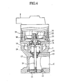
- reference numeral 1 denotes a valve body having formed therein a passage which forms a part of an exhaust gas recirculation passage c interposed in a recirculation system of the exhaust gas.
- Reference numeral 2 denotes a motor case for housing therein an electric motor M.
- reference numeral 21 denotes a rotor around which is wound by a coil 22, and reference numeral 23 denotes a yoke provided with a magnet 24.
- the lower end portion of the rotor 21 is rotatably supported on the valve body 1 by a bearing 27.
- a motor shaft 31 Inside the rotor 21, there is threadedly engaged a motor shaft 31.
- the motor shaft 31 is prevented from relatively rotating by a guide bush 13 on the body 1. Therefore, it follows that the motor shaft 31 moves upward and downward depending on the amount of rotation of the rotor 21.
- a valve shaft 14 is provided in contact with the lower end of the motor shaft 31, and an intermediate portion of the valve shaft 14 is guided by a guide seal 15 and a guide plate 16 so as to be movable upward and downward.
- the control valve 11 is attached to the lower end of the valve shaft 14.
- Reference numeral 17 denotes a guide seal cover. Between a spring sheet 18 mounted on the upper end of the valve shaft 14 and the guide plate 16, there is interposed a return spring 19 for urging the valve shaft 14 in an upward direction, i.e., for urging the control valve 11 in a valve-closing direction.
- the control valve 11 constituted as described above is driven by a torque balance system as described above.
- the control valve 11 is given a predetermined return torque in the valve-closing direction of the control valve 11 by the return spring 19 serving as the urging means, and is also given a variable motor torque in the valve-opening direction by the driving of the electric motor M. By the balance of these torque, the open/close of the control valve 11 is controlled.
- FIG. 5 is a circuit block diagram showing an engine controller unit (ECU) 51 which supplies the electric motor M with a driving signal.
- Reference numeral 50 denotes a control part in the form of a microcomputer which determines the driving force of the electric motor M.
- Reference numeral 52 denotes a battery.
- Reference numeral 53 denotes a motor driving force converting part which converts the output of the control part 50 for supplying to the electric motor M, and is made up of: a Zener diode 53a; a diode 53b for forcing the current flow to the electric motor M unidirectional; a field-effect transistor (FET) 53c; and an interface 53d which is provided between the control part 50 and the FET 53c.
- Reference numeral 56 denotes a regulator to ensure a driving voltage (5V) for the control part 50.
- the control part 50 receives as inputs through interfaces 58, 59, respectively, a detected signal from an operating state amount sensor 57 mounted on each part of the vehicle such as a crank angle sensor or the like, as well as a detected signal from a position sensor 40.
- the position sensor 40 in this example is provided with a movable contact part 42 for moving on a resistor 41 to which is applied a constant voltage (5V) from a voltage supply part 60.
- a constant voltage 5V
- the above-described motor driving force converting part 53 switches on and off the voltage to be applied to the electric motor M at a constant period.
- PWM pulse-width modulation
- the conventional apparatus for controlling the EGR valve is constituted as described above, there is the following problem, i.e., in case the closing position of the control valve changes with the lapse of time due to wear of the control valve, the valve seat, or the like, the open position of the control valve and the rotor origin point of the electric motor deviate from each other, with the result that the valve-opening starting position with which the valve opening of the control valve is started changes and that the control valve can no longer be accurately controlled.
- This invention has been made to solve the above and other problems and has an object of obtaining an apparatus for controlling an EGR valve in which the valve-opening starting position is accurately detected and the valve opening control is accurately performed.
- this invention has an object of obtaining an apparatus for controlling an EGR valve in which the motor shaft can be prevented, at the time of valve closing, from strongly striking a stopper which restricts the operating range of the electric motor.
- An apparatus for controlling an exhaust gas recirculation (EGR) valve comprises: a valve shaft having an open-close valve; a return spring for urging the valve shaft in a valve-closing direction; an electric motor for driving in a valve-opening direction a motor shaft abutting the valve shaft; a position detecting sensor for detecting a position of the motor shaft; and a computing means for computing a valve-opening starting position based on a detected signal of the position detecting sensor which detects, through movement of the motor shaft back and forth in both the valve-opening direction and the valve-closing direction, related positions of the motor shaft and the valve shaft at the time of the movement.
- EGR exhaust gas recirculation
- the apparatus for controlling an EGR valve according to this invention is characterized in that opening and closing operation of the open-close valve is repeated several times prior to an operation of detecting the valve-opening position.
- the seating situation of the valve on the valve seat is improved.
- the detection of the valve-opening starting position is performed surely and accurately, whereby the amount of valve opening can be controlled more accurately.
- the apparatus for controlling an EGR valve according to this invention further comprises an assisting spring for urging the motor shaft in a direction opposite to that of the return spring, the urging being made with a force smaller than that of the return spring.
- the motor shaft pushed back by the urging force of the return spring at the time of closing the valve is prevented from being strongly striking a stopper which restricts the operating range of the electric motor, thereby preventing the motor shaft from being damaged. Further, the valve-opening position at which the valve starts to open is accurately detectable, whereby the amount of valve opening is accurately controllable.
- the apparatus for controlling an EGR valve is characterized in that the computing means: drives the electric motor, thereby opening the open-close valve by urging the valve shaft with the motor shaft; thereafter sequentially weakens the driving force of the electric motor so as to move the valve shaft in the valve-closing direction by an urging force of the return spring, thereby detecting a motor shaft position at the time of valve closing as a fully-closed position; further moves the motor shaft in a direction away from the valve shaft and thereafter moves the motor shaft once again in a direction to come into contact with the valve shaft, thereby detecting the contact position of the motor shaft with the valve shaft as a confirmation position; and if a deviation between the confirmation position and the fully-closed position falls within a tolerance (tolerable deviation), makes the fully-closed position as the valve-opening starting position.
- the computing means drives the electric motor, thereby opening the open-close valve by urging the valve shaft with the motor shaft; thereafter sequentially weakens the driving force of the electric motor so as to move the valve shaft in the
- the valve-opening starting position at which the valve starts to open can be accurately detected and, therefore, the amount of the valve opening can be accurately controlled.
- the apparatus for controlling an EGR valve is characterized in that the computing means: drives the electric motor, thereby opening the open-close valve by urging the valve shaft with the motor shaft; thereafter sequentially weakens the driving force of the electric motor so as to move the valve shaft in a valve-closing direction by an urging force of the return spring, thereby detecting the motor shaft position at the time of valve closing as a fully-closed position; further moves the motor shaft in a direction away from the valve shaft and thereafter moves the motor shaft once again in a direction to come into contact with the valve shaft, thereby detecting the contact position of the motor shaft with the valve shaft as a confirmation position; and if a deviation between the confirmation position and the fully-closed position falls outside a tolerable deviation, repeats the above-described operations once again to thereby detect whether the deviation between the confirmation position and the fully-closed position falls within the tolerable deviation.
- the valve-opening starting position at which the valve starts to open can be accurately detected and, therefore, the amount of opening the valve can be accurately controlled.
- the apparatus for controlling an EGR valve is characterized in that the computing means: sequentially increases a driving force to be supplied to the electric motor in the valve-opening direction, thereby detecting a duty at which the driving force changes as a result of contact of the motor shaft with the valve shaft; opens the open-close valve by sequentially increasing the driving force of the electric motor and thereafter closes the open-close valve by sequentially decreasing the driving force of the electric motor, thereby detecting a duty at which the driving force changes as a result of departing of the motor shaft from the valve shaft; and if a deviation between this duty and the earlier detected duty falls within a tolerable deviation, makes that position of the motor shaft at which the earlier detected duty was detected as the valve-opening starting position.
- the valve-opening starting position at which the valve starts to open can be accurately detected and, therefore, the amount of operating the valve opening can be accurately controlled.
- a valve shaft 14 is moved by pushing with a motor shaft 31 to thereby open the valve.
- the valve shaft 14 is moved by the urging force of a return spring 19 in the valve-closing direction to detect the position of the motor shaft at the time of valve closing as a fully-closed position (region A in FIG. 7). Further, after moving the motor shaft 31 in the direction away from the valve shaft 14, the motor shaft 31 is moved again in the direction of coming into contact with the valve shaft 14 to thereby detect the position of contact of the motor shaft 31 with the valve shaft 14 as a confirmation position (region B in FIG. 7). If a deviation between this confirmation position and the fully-closed position falls within a tolerance (tolerable deviation), the fully closed position is defined as a valve-opening starting position.
- the program transfers to an interruption processing as shown in FIG. 9.
- Adetermination is made whether the sequence is "1" or not. If the result of the determination is YES, the program transfers to the preparation for a preliminary operation as shown in FIG. 10, and the sequence is made to "2" in the course of performing this preparation for the preliminary operation. After carrying out the performance of the preliminary operation shown in FIG. 11, the sequence is made to "3". Thereafter, in accordance with sequence transferrings of "4" through "10", there will be carried out each of the interruption operations of: valve-opening preparation as shown in FIG. 12; valve opening for hysteresis detection as shown in FIG. 13; preparation for hysteresis detection as shown in FIG.
- RETRY denotes the number of operations
- STATUS2 denotes representation of states such as normal, abnormal, and the like
- SEQ denotes sequence
- TIME denotes interruption time given to each sequence
- D(t) and D1 through D4 denote the DUTY which is the driving force to be given to the electric motor
- ⁇ S denotes the deviation between the present sensor output value S (t) and the previous sensor output value S(t-1), respectively.
- the tolerable deviation and the target valve-opening position are arbitrarily determined in advance.
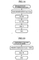
- step ST8 the timer interruption is released (step ST8), and a determination is made as to whether the status is normal or not (step ST9). If the result of the determination is YES, a flag for detecting the voltage at the point of origin is made to be normal (step ST10) and the operation is completed.
- step ST9 determines whether the number of retrying has exceeded a set value or not. If the determination result is YES, the flag for detecting the voltage at the point of origin is made to be abnormal (step ST13) and the operation is completed.
- the detected parameter e.g., the driving duty of the electric motor M is changed according to the status so that the program returns to the step ST3 to thereby repeat the operations of step ST3 and downward (step ST14).
- the amount of valve opening maybe accurately controlled by enabling to accurately detect the valve-opening starting position at the time of opening the valve.
- FIG. 20 is a diagram showing the relationships of stroke change of a motor shaft and motor driving force (duty) with respect to time, to describe the operation of detecting the valve-opening position according to an embodiment 2 of this invention.
- First there are repeated several times an operation of opening a valve by giving a valve-opening driving force (duty) to an electric motor M to thereby open the valve and immediately bringing the driving force to "0" to thereby open the valve by an urging force of a return spring. Thereafter, as shown in FIG. 20, by sequentially increasing the driving force in the valve-opening direction to be supplied to the electric motor M, the duty at which the driving force is changed as a result of contact of the motor shaft 31 with the valve shaft 14 is detected.
- a valve-opening driving force duty
- FIG. 21 is a flow chart for performing the detection of the position for valve opening, and is to perform the similar operations as in FIG. 16. Therefore, its detailed description is omitted.
- the amount of valve opening can be accurately controlled.
- FIG. 22 is a partially cut-away longitudinal sectional view of the EGR valve according to embodiment 3 of this invention.
- reference numeral 32 denotes an assisting spring which urges the motor shaft 31 in the valve-opening direction with a force smaller than the valve-opening force.
- the other constitution is the same as that shown in FIG. 4. Therefore, its description is omitted by giving the same reference numerals to the same parts.
- the urging force of the return spring 19 gets stronger than the driving force of the electric motor M.
- the valve shaft 14 is urged to move in the valve-closing direction while pushing the motor shaft 31.
- the assisting spring 32 is compressed by the spring sheet 33 so that the urging force becomes stronger.
- the amount of movement of the motor shaft 31 in the valve-closing direction is restricted.
- the apparatus for controlling the EGR valve according to this invention is suitable for quickly performing the operation of returning part of the exhaust gas in the exhaust passage "a" to the intake passage b in response to the change in the engine operating conditions.
Landscapes
- Engineering & Computer Science (AREA)
- Chemical & Material Sciences (AREA)
- Combustion & Propulsion (AREA)
- Mechanical Engineering (AREA)
- General Engineering & Computer Science (AREA)
- Analytical Chemistry (AREA)
- Exhaust-Gas Circulating Devices (AREA)
Abstract
Description
Claims (6)
- An apparatus for controlling an exhaust gas recirculation valve comprising:a valve shaft having an open-close valve;a return spring for urging said valve shaft in a valve-closing direction;an electric motor for driving, in a valve-opening direction, a motor shaft abutting said valve shaft;a position detecting sensor for detecting a position of said motor shaft; anda computing means for computing a valve-opening starting position based on a detected signal of said position detecting sensor which detects, through movement of said motor shaft back and forth in both the valve-opening direction and the valve-closing direction, related positions of said motor shaft and said valve shaft at the time of the movement.
- The apparatus for controlling an EGR valve according to claim 1, wherein opening and closing operation of said open-close valve is repeated several times prior to an operation of detecting the valve-opening position.
- The apparatus for controlling an EGR valve according to claim 1, further comprising an assisting spring for urging said motor shaft in a direction opposite to that of said return spring, said urging being made with a force smaller than that of said return spring.
- The apparatus for controlling an EGR valve according to claim 1, wherein said computing means:drives said electric motor, thereby opening said open-close valve by urging said valve shaft with said motor shaft;thereafter sequentially weakens the driving force of said electric motor so as to move said valve shaft in the valve-closing direction by an urging force of said return spring, thereby detecting a motor shaft position at the time of valve closing as a fully-closed position;further moves said motor shaft in a direction away from said valve shaft and thereafter moves said motor shaft once again in a direction to come into contact with said valve shaft, thereby detecting the contact position of said motor shaft with said valve shaft as a confirmation position; andif a deviation between said confirmation position and said fully-closed position falls within a tolerable deviation, makes said fully-closed position as said valve-opening starting position.
- The apparatus for controlling an EGR valve according to claim 1, wherein said computing means:drives said electric motor, thereby opening said open-close valve by urging said valve shaft with said motor shaft;thereafter sequentially weakens the driving force of said electric motor so as to move said valve shaft in a valve-closing direction by an urging force of said return spring, thereby detecting the motor shaft position at the time of valve closing as a fully-closed position;further moves said motor shaft in a direction away from said valve shaft and thereafter moves said motor shaft once again in a direction to come into contact with said valve shaft, thereby detecting the contact position of said motor shaft with said valve shaft as a confirmation position; andif a deviation between said confirmation position and said fully-closed position falls outside a tolerable deviation, repeats the above-described operations once again to thereby detect whether the deviation between said confirmation position and said fully-closed position falls within the tolerable deviation.
- The apparatus for controlling an EGR valve according to claim 1, wherein said computing means:sequentially increases a driving force to be supplied to said electric motor in the valve-opening direction, thereby detecting a duty at which the driving force changes as a result of contact of said motor shaft with said valve shaft;opens said open-close valve by sequentially increasing the driving force of said electric motor and thereafter closes said open-close valve by sequentially decreasing the driving force of said electric motor, thereby detecting a duty at which the driving force changes as a result of departing of said motor shaft from said valve shaft; andif a deviation between this duty and the earlier detected duty falls within a tolerable deviation, makes that position of said motor shaft at which the earlier detected duty was detected as said valve-opening starting position.
Applications Claiming Priority (1)
| Application Number | Priority Date | Filing Date | Title |
|---|---|---|---|
| PCT/JP2000/005718 WO2002016751A1 (en) | 2000-08-24 | 2000-08-24 | Exhaust gas recirculation valve controller |
Publications (3)
| Publication Number | Publication Date |
|---|---|
| EP1312786A1 true EP1312786A1 (en) | 2003-05-21 |
| EP1312786A4 EP1312786A4 (en) | 2005-05-11 |
| EP1312786B1 EP1312786B1 (en) | 2010-11-17 |
Family
ID=11736391
Family Applications (1)
| Application Number | Title | Priority Date | Filing Date |
|---|---|---|---|
| EP00955000A Expired - Lifetime EP1312786B1 (en) | 2000-08-24 | 2000-08-24 | Exhaust gas recirculation valve controller |
Country Status (6)
| Country | Link |
|---|---|
| US (1) | US6688294B1 (en) |
| EP (1) | EP1312786B1 (en) |
| JP (1) | JP4241035B2 (en) |
| KR (1) | KR100514336B1 (en) |
| DE (1) | DE60045261D1 (en) |
| WO (1) | WO2002016751A1 (en) |
Cited By (2)
| Publication number | Priority date | Publication date | Assignee | Title |
|---|---|---|---|---|
| US10094485B2 (en) | 2008-07-18 | 2018-10-09 | Flowserve Management Company | Variable-speed actuator |
| EP2313674B1 (en) * | 2008-07-18 | 2020-05-13 | Flowserve Management Company | Variable speed actuator |
Families Citing this family (4)
| Publication number | Priority date | Publication date | Assignee | Title |
|---|---|---|---|---|
| JP4600304B2 (en) * | 2006-01-26 | 2010-12-15 | いすゞ自動車株式会社 | EGR valve control device |
| CN102076949B (en) * | 2008-08-01 | 2013-06-05 | 三菱电机株式会社 | Valve control apparatus and valve apparatus |
| US8423269B2 (en) * | 2009-07-08 | 2013-04-16 | Cummins Inc. | Exhaust gas recirculation valve contaminant removal |
| US20240011454A1 (en) * | 2022-07-07 | 2024-01-11 | International Engine Intellectual Property Company, Llc | Exhaust gas recirculation valve diagnostics |
Family Cites Families (16)
| Publication number | Priority date | Publication date | Assignee | Title |
|---|---|---|---|---|
| JPS5762954A (en) * | 1980-09-30 | 1982-04-16 | Aisin Seiki Co Ltd | Egr control valve apparatus and its control method |
| JPS62279261A (en) * | 1986-05-28 | 1987-12-04 | Mitsubishi Electric Corp | Egr valve control device |
| JPH05106752A (en) * | 1991-10-17 | 1993-04-27 | Honda Motor Co Ltd | Valve system |
| JP3546469B2 (en) * | 1994-06-03 | 2004-07-28 | 三菱電機株式会社 | Flow valve control device |
| JPH08114157A (en) * | 1994-10-14 | 1996-05-07 | Nippondenso Co Ltd | Exhaust gas reflux valve control device |
| JPH08326952A (en) * | 1995-06-05 | 1996-12-10 | Nippondenso Co Ltd | Operation failure diagnosis device for flow rate control valve |
| JP3075181B2 (en) * | 1996-06-12 | 2000-08-07 | トヨタ自動車株式会社 | Abnormality determination device for exhaust gas recirculation device |
| JP3750201B2 (en) * | 1996-07-04 | 2006-03-01 | マツダ株式会社 | Exhaust gas recirculation apparatus failure diagnosis method and apparatus |
| JP3379380B2 (en) * | 1997-04-23 | 2003-02-24 | 日立電線株式会社 | High strength and high conductivity copper alloy |
| JPH1162716A (en) * | 1997-08-27 | 1999-03-05 | Toyota Motor Corp | Exhaust gas recirculation control device for internal combustion engine |
| JPH11132110A (en) * | 1997-10-28 | 1999-05-18 | Unisia Jecs Corp | Control device for EGR valve |
| JPH11159405A (en) | 1997-11-27 | 1999-06-15 | Unisia Jecs Corp | Control device for EGR valve |
| JP4082478B2 (en) * | 1998-06-24 | 2008-04-30 | 富士重工業株式会社 | Control device for electromagnetically driven valve |
| US6012437A (en) * | 1998-07-06 | 2000-01-11 | Eaton Corporation | EGR system with improved control logic |
| JP3371856B2 (en) * | 1999-07-22 | 2003-01-27 | 三菱電機株式会社 | Electric control valve device |
| EP1174614B1 (en) * | 2000-02-25 | 2005-06-08 | Mitsubishi Denki Kabushiki Kaisha | Controller of exhaust gas recirculation valve |
-
2000
- 2000-08-24 WO PCT/JP2000/005718 patent/WO2002016751A1/en not_active Ceased
- 2000-08-24 EP EP00955000A patent/EP1312786B1/en not_active Expired - Lifetime
- 2000-08-24 KR KR10-2002-7004686A patent/KR100514336B1/en not_active Expired - Lifetime
- 2000-08-24 US US10/110,329 patent/US6688294B1/en not_active Expired - Lifetime
- 2000-08-24 DE DE60045261T patent/DE60045261D1/en not_active Expired - Lifetime
- 2000-08-24 JP JP2002522414A patent/JP4241035B2/en not_active Expired - Lifetime
Cited By (2)
| Publication number | Priority date | Publication date | Assignee | Title |
|---|---|---|---|---|
| US10094485B2 (en) | 2008-07-18 | 2018-10-09 | Flowserve Management Company | Variable-speed actuator |
| EP2313674B1 (en) * | 2008-07-18 | 2020-05-13 | Flowserve Management Company | Variable speed actuator |
Also Published As
| Publication number | Publication date |
|---|---|
| EP1312786A4 (en) | 2005-05-11 |
| JP4241035B2 (en) | 2009-03-18 |
| EP1312786B1 (en) | 2010-11-17 |
| KR100514336B1 (en) | 2005-09-13 |
| DE60045261D1 (en) | 2010-12-30 |
| WO2002016751A1 (en) | 2002-02-28 |
| KR20020037383A (en) | 2002-05-18 |
| US6688294B1 (en) | 2004-02-10 |
Similar Documents
| Publication | Publication Date | Title |
|---|---|---|
| US8165784B2 (en) | Apparatus and method for learning reference position of variable valve unit | |
| CN101573525B (en) | Egr valve control device | |
| WO2006062043A1 (en) | Motor type poppet valve and egr device of internal combustion engine using the motor type poppet valve | |
| JP3826014B2 (en) | Electronic throttle control device | |
| EP0911506A3 (en) | Electronically controlled throttle apparatus for an engine | |
| US20070186886A1 (en) | Apparatus for and method of controlling motion mechanism | |
| EP1312786B1 (en) | Exhaust gas recirculation valve controller | |
| JP2001512256A (en) | Improving control accuracy of pulsed electromechanical devices | |
| CN107407196B (en) | Control device of actuator, actuator, valve driving device, and control method of actuator | |
| EP1310660B1 (en) | Method for controlling exhaust gas recirculation valve | |
| EP1329619B1 (en) | Engine suction valve open/close control device by electromagnetic actuator | |
| US5333584A (en) | Throttle control system | |
| US6523522B1 (en) | Method and apparatus for operating a throttle plate motor driving a throttle plate having opposing return springs | |
| US7640093B2 (en) | Electronic throttle control apparatus | |
| JPWO2002016751A1 (en) | Exhaust gas recirculation valve control device | |
| JPH07279693A (en) | Drive for throttle valve | |
| JPH11159405A (en) | Control device for EGR valve | |
| US6729314B2 (en) | Staged translation control algorithm for reduction in impact force | |
| JP2722624B2 (en) | Control method of stepper motor driven exhaust gas recirculation control valve | |
| JPH10220620A (en) | Control device for EGR valve | |
| JPH11132110A (en) | Control device for EGR valve | |
| JP4480938B2 (en) | Exhaust gas recirculation valve control method | |
| JPH06167262A (en) | Controller for idle adjusting valve of engine | |
| JP3646545B2 (en) | Electronically controlled throttle valve control device | |
| JPH11173167A (en) | Throttle valve device |
Legal Events
| Date | Code | Title | Description |
|---|---|---|---|
| PUAI | Public reference made under article 153(3) epc to a published international application that has entered the european phase |
Free format text: ORIGINAL CODE: 0009012 |
|
| 17P | Request for examination filed |
Effective date: 20020418 |
|
| AK | Designated contracting states |
Designated state(s): AT BE CH CY DE DK ES FI FR GB GR IE IT LI LU MC NL PT SE |
|
| RBV | Designated contracting states (corrected) |
Designated state(s): AT DE |
|
| A4 | Supplementary search report drawn up and despatched |
Effective date: 20050401 |
|
| RAP1 | Party data changed (applicant data changed or rights of an application transferred) |
Owner name: MITSUBISHI DENKI KABUSHIKI KAISHA |
|
| 17Q | First examination report despatched |
Effective date: 20060928 |
|
| GRAP | Despatch of communication of intention to grant a patent |
Free format text: ORIGINAL CODE: EPIDOSNIGR1 |
|
| RBV | Designated contracting states (corrected) |
Designated state(s): DE |
|
| GRAS | Grant fee paid |
Free format text: ORIGINAL CODE: EPIDOSNIGR3 |
|
| GRAA | (expected) grant |
Free format text: ORIGINAL CODE: 0009210 |
|
| AK | Designated contracting states |
Kind code of ref document: B1 Designated state(s): DE |
|
| REF | Corresponds to: |
Ref document number: 60045261 Country of ref document: DE Date of ref document: 20101230 Kind code of ref document: P |
|
| PLBE | No opposition filed within time limit |
Free format text: ORIGINAL CODE: 0009261 |
|
| STAA | Information on the status of an ep patent application or granted ep patent |
Free format text: STATUS: NO OPPOSITION FILED WITHIN TIME LIMIT |
|
| 26N | No opposition filed |
Effective date: 20110818 |
|
| REG | Reference to a national code |
Ref country code: DE Ref legal event code: R097 Ref document number: 60045261 Country of ref document: DE Effective date: 20110818 |
|
| REG | Reference to a national code |
Ref country code: DE Ref legal event code: R084 Ref document number: 60045261 Country of ref document: DE Effective date: 20130503 |
|
| PGFP | Annual fee paid to national office [announced via postgrant information from national office to epo] |
Ref country code: DE Payment date: 20190813 Year of fee payment: 20 |
|
| REG | Reference to a national code |
Ref country code: DE Ref legal event code: R071 Ref document number: 60045261 Country of ref document: DE |