EP1302353B1 - Control device and control method for hybrid vehicle - Google Patents
Control device and control method for hybrid vehicle Download PDFInfo
- Publication number
- EP1302353B1 EP1302353B1 EP02021102A EP02021102A EP1302353B1 EP 1302353 B1 EP1302353 B1 EP 1302353B1 EP 02021102 A EP02021102 A EP 02021102A EP 02021102 A EP02021102 A EP 02021102A EP 1302353 B1 EP1302353 B1 EP 1302353B1
- Authority
- EP
- European Patent Office
- Prior art keywords
- target
- operating point
- unit operating
- unit
- internal combustion
- Prior art date
- Legal status (The legal status is an assumption and is not a legal conclusion. Google has not performed a legal analysis and makes no representation as to the accuracy of the status listed.)
- Expired - Lifetime
Links
Images






Classifications
-
- B—PERFORMING OPERATIONS; TRANSPORTING
- B60—VEHICLES IN GENERAL
- B60L—PROPULSION OF ELECTRICALLY-PROPELLED VEHICLES; SUPPLYING ELECTRIC POWER FOR AUXILIARY EQUIPMENT OF ELECTRICALLY-PROPELLED VEHICLES; ELECTRODYNAMIC BRAKE SYSTEMS FOR VEHICLES IN GENERAL; MAGNETIC SUSPENSION OR LEVITATION FOR VEHICLES; MONITORING OPERATING VARIABLES OF ELECTRICALLY-PROPELLED VEHICLES; ELECTRIC SAFETY DEVICES FOR ELECTRICALLY-PROPELLED VEHICLES
- B60L58/00—Methods or circuit arrangements for monitoring or controlling batteries or fuel cells, specially adapted for electric vehicles
- B60L58/10—Methods or circuit arrangements for monitoring or controlling batteries or fuel cells, specially adapted for electric vehicles for monitoring or controlling batteries
- B60L58/12—Methods or circuit arrangements for monitoring or controlling batteries or fuel cells, specially adapted for electric vehicles for monitoring or controlling batteries responding to state of charge [SoC]
- B60L58/15—Preventing overcharging
-
- B—PERFORMING OPERATIONS; TRANSPORTING
- B60—VEHICLES IN GENERAL
- B60K—ARRANGEMENT OR MOUNTING OF PROPULSION UNITS OR OF TRANSMISSIONS IN VEHICLES; ARRANGEMENT OR MOUNTING OF PLURAL DIVERSE PRIME-MOVERS IN VEHICLES; AUXILIARY DRIVES FOR VEHICLES; INSTRUMENTATION OR DASHBOARDS FOR VEHICLES; ARRANGEMENTS IN CONNECTION WITH COOLING, AIR INTAKE, GAS EXHAUST OR FUEL SUPPLY OF PROPULSION UNITS IN VEHICLES
- B60K6/00—Arrangement or mounting of plural diverse prime-movers for mutual or common propulsion, e.g. hybrid propulsion systems comprising electric motors and internal combustion engines
- B60K6/20—Arrangement or mounting of plural diverse prime-movers for mutual or common propulsion, e.g. hybrid propulsion systems comprising electric motors and internal combustion engines the prime-movers consisting of electric motors and internal combustion engines, e.g. HEVs
- B60K6/42—Arrangement or mounting of plural diverse prime-movers for mutual or common propulsion, e.g. hybrid propulsion systems comprising electric motors and internal combustion engines the prime-movers consisting of electric motors and internal combustion engines, e.g. HEVs characterised by the architecture of the hybrid electric vehicle
- B60K6/48—Parallel type
-
- B—PERFORMING OPERATIONS; TRANSPORTING
- B60—VEHICLES IN GENERAL
- B60K—ARRANGEMENT OR MOUNTING OF PROPULSION UNITS OR OF TRANSMISSIONS IN VEHICLES; ARRANGEMENT OR MOUNTING OF PLURAL DIVERSE PRIME-MOVERS IN VEHICLES; AUXILIARY DRIVES FOR VEHICLES; INSTRUMENTATION OR DASHBOARDS FOR VEHICLES; ARRANGEMENTS IN CONNECTION WITH COOLING, AIR INTAKE, GAS EXHAUST OR FUEL SUPPLY OF PROPULSION UNITS IN VEHICLES
- B60K6/00—Arrangement or mounting of plural diverse prime-movers for mutual or common propulsion, e.g. hybrid propulsion systems comprising electric motors and internal combustion engines
- B60K6/20—Arrangement or mounting of plural diverse prime-movers for mutual or common propulsion, e.g. hybrid propulsion systems comprising electric motors and internal combustion engines the prime-movers consisting of electric motors and internal combustion engines, e.g. HEVs
- B60K6/50—Architecture of the driveline characterised by arrangement or kind of transmission units
- B60K6/54—Transmission for changing ratio
- B60K6/543—Transmission for changing ratio the transmission being a continuously variable transmission
-
- B—PERFORMING OPERATIONS; TRANSPORTING
- B60—VEHICLES IN GENERAL
- B60K—ARRANGEMENT OR MOUNTING OF PROPULSION UNITS OR OF TRANSMISSIONS IN VEHICLES; ARRANGEMENT OR MOUNTING OF PLURAL DIVERSE PRIME-MOVERS IN VEHICLES; AUXILIARY DRIVES FOR VEHICLES; INSTRUMENTATION OR DASHBOARDS FOR VEHICLES; ARRANGEMENTS IN CONNECTION WITH COOLING, AIR INTAKE, GAS EXHAUST OR FUEL SUPPLY OF PROPULSION UNITS IN VEHICLES
- B60K6/00—Arrangement or mounting of plural diverse prime-movers for mutual or common propulsion, e.g. hybrid propulsion systems comprising electric motors and internal combustion engines
- B60K6/20—Arrangement or mounting of plural diverse prime-movers for mutual or common propulsion, e.g. hybrid propulsion systems comprising electric motors and internal combustion engines the prime-movers consisting of electric motors and internal combustion engines, e.g. HEVs
- B60K6/50—Architecture of the driveline characterised by arrangement or kind of transmission units
- B60K6/54—Transmission for changing ratio
- B60K6/547—Transmission for changing ratio the transmission being a stepped gearing
-
- B—PERFORMING OPERATIONS; TRANSPORTING
- B60—VEHICLES IN GENERAL
- B60L—PROPULSION OF ELECTRICALLY-PROPELLED VEHICLES; SUPPLYING ELECTRIC POWER FOR AUXILIARY EQUIPMENT OF ELECTRICALLY-PROPELLED VEHICLES; ELECTRODYNAMIC BRAKE SYSTEMS FOR VEHICLES IN GENERAL; MAGNETIC SUSPENSION OR LEVITATION FOR VEHICLES; MONITORING OPERATING VARIABLES OF ELECTRICALLY-PROPELLED VEHICLES; ELECTRIC SAFETY DEVICES FOR ELECTRICALLY-PROPELLED VEHICLES
- B60L15/00—Methods, circuits, or devices for controlling the traction-motor speed of electrically-propelled vehicles
- B60L15/20—Methods, circuits, or devices for controlling the traction-motor speed of electrically-propelled vehicles for control of the vehicle or its driving motor to achieve a desired performance, e.g. speed, torque, programmed variation of speed
-
- B—PERFORMING OPERATIONS; TRANSPORTING
- B60—VEHICLES IN GENERAL
- B60L—PROPULSION OF ELECTRICALLY-PROPELLED VEHICLES; SUPPLYING ELECTRIC POWER FOR AUXILIARY EQUIPMENT OF ELECTRICALLY-PROPELLED VEHICLES; ELECTRODYNAMIC BRAKE SYSTEMS FOR VEHICLES IN GENERAL; MAGNETIC SUSPENSION OR LEVITATION FOR VEHICLES; MONITORING OPERATING VARIABLES OF ELECTRICALLY-PROPELLED VEHICLES; ELECTRIC SAFETY DEVICES FOR ELECTRICALLY-PROPELLED VEHICLES
- B60L50/00—Electric propulsion with power supplied within the vehicle
- B60L50/10—Electric propulsion with power supplied within the vehicle using propulsion power supplied by engine-driven generators, e.g. generators driven by combustion engines
- B60L50/16—Electric propulsion with power supplied within the vehicle using propulsion power supplied by engine-driven generators, e.g. generators driven by combustion engines with provision for separate direct mechanical propulsion
-
- B—PERFORMING OPERATIONS; TRANSPORTING
- B60—VEHICLES IN GENERAL
- B60W—CONJOINT CONTROL OF VEHICLE SUB-UNITS OF DIFFERENT TYPE OR DIFFERENT FUNCTION; CONTROL SYSTEMS SPECIALLY ADAPTED FOR HYBRID VEHICLES; ROAD VEHICLE DRIVE CONTROL SYSTEMS FOR PURPOSES NOT RELATED TO THE CONTROL OF A PARTICULAR SUB-UNIT
- B60W10/00—Conjoint control of vehicle sub-units of different type or different function
- B60W10/04—Conjoint control of vehicle sub-units of different type or different function including control of propulsion units
- B60W10/06—Conjoint control of vehicle sub-units of different type or different function including control of propulsion units including control of combustion engines
-
- B—PERFORMING OPERATIONS; TRANSPORTING
- B60—VEHICLES IN GENERAL
- B60W—CONJOINT CONTROL OF VEHICLE SUB-UNITS OF DIFFERENT TYPE OR DIFFERENT FUNCTION; CONTROL SYSTEMS SPECIALLY ADAPTED FOR HYBRID VEHICLES; ROAD VEHICLE DRIVE CONTROL SYSTEMS FOR PURPOSES NOT RELATED TO THE CONTROL OF A PARTICULAR SUB-UNIT
- B60W10/00—Conjoint control of vehicle sub-units of different type or different function
- B60W10/04—Conjoint control of vehicle sub-units of different type or different function including control of propulsion units
- B60W10/08—Conjoint control of vehicle sub-units of different type or different function including control of propulsion units including control of electric propulsion units, e.g. motors or generators
-
- B—PERFORMING OPERATIONS; TRANSPORTING
- B60—VEHICLES IN GENERAL
- B60W—CONJOINT CONTROL OF VEHICLE SUB-UNITS OF DIFFERENT TYPE OR DIFFERENT FUNCTION; CONTROL SYSTEMS SPECIALLY ADAPTED FOR HYBRID VEHICLES; ROAD VEHICLE DRIVE CONTROL SYSTEMS FOR PURPOSES NOT RELATED TO THE CONTROL OF A PARTICULAR SUB-UNIT
- B60W10/00—Conjoint control of vehicle sub-units of different type or different function
- B60W10/10—Conjoint control of vehicle sub-units of different type or different function including control of change-speed gearings
-
- B—PERFORMING OPERATIONS; TRANSPORTING
- B60—VEHICLES IN GENERAL
- B60W—CONJOINT CONTROL OF VEHICLE SUB-UNITS OF DIFFERENT TYPE OR DIFFERENT FUNCTION; CONTROL SYSTEMS SPECIALLY ADAPTED FOR HYBRID VEHICLES; ROAD VEHICLE DRIVE CONTROL SYSTEMS FOR PURPOSES NOT RELATED TO THE CONTROL OF A PARTICULAR SUB-UNIT
- B60W10/00—Conjoint control of vehicle sub-units of different type or different function
- B60W10/24—Conjoint control of vehicle sub-units of different type or different function including control of energy storage means
- B60W10/26—Conjoint control of vehicle sub-units of different type or different function including control of energy storage means for electrical energy, e.g. batteries or capacitors
-
- B—PERFORMING OPERATIONS; TRANSPORTING
- B60—VEHICLES IN GENERAL
- B60W—CONJOINT CONTROL OF VEHICLE SUB-UNITS OF DIFFERENT TYPE OR DIFFERENT FUNCTION; CONTROL SYSTEMS SPECIALLY ADAPTED FOR HYBRID VEHICLES; ROAD VEHICLE DRIVE CONTROL SYSTEMS FOR PURPOSES NOT RELATED TO THE CONTROL OF A PARTICULAR SUB-UNIT
- B60W20/00—Control systems specially adapted for hybrid vehicles
-
- B—PERFORMING OPERATIONS; TRANSPORTING
- B60—VEHICLES IN GENERAL
- B60W—CONJOINT CONTROL OF VEHICLE SUB-UNITS OF DIFFERENT TYPE OR DIFFERENT FUNCTION; CONTROL SYSTEMS SPECIALLY ADAPTED FOR HYBRID VEHICLES; ROAD VEHICLE DRIVE CONTROL SYSTEMS FOR PURPOSES NOT RELATED TO THE CONTROL OF A PARTICULAR SUB-UNIT
- B60W20/00—Control systems specially adapted for hybrid vehicles
- B60W20/10—Controlling the power contribution of each of the prime movers to meet required power demand
- B60W20/13—Controlling the power contribution of each of the prime movers to meet required power demand in order to stay within battery power input or output limits; in order to prevent overcharging or battery depletion
-
- B—PERFORMING OPERATIONS; TRANSPORTING
- B60—VEHICLES IN GENERAL
- B60W—CONJOINT CONTROL OF VEHICLE SUB-UNITS OF DIFFERENT TYPE OR DIFFERENT FUNCTION; CONTROL SYSTEMS SPECIALLY ADAPTED FOR HYBRID VEHICLES; ROAD VEHICLE DRIVE CONTROL SYSTEMS FOR PURPOSES NOT RELATED TO THE CONTROL OF A PARTICULAR SUB-UNIT
- B60W50/00—Details of control systems for road vehicle drive control not related to the control of a particular sub-unit, e.g. process diagnostic or vehicle driver interfaces
- B60W50/0097—Predicting future conditions
-
- B—PERFORMING OPERATIONS; TRANSPORTING
- B60—VEHICLES IN GENERAL
- B60L—PROPULSION OF ELECTRICALLY-PROPELLED VEHICLES; SUPPLYING ELECTRIC POWER FOR AUXILIARY EQUIPMENT OF ELECTRICALLY-PROPELLED VEHICLES; ELECTRODYNAMIC BRAKE SYSTEMS FOR VEHICLES IN GENERAL; MAGNETIC SUSPENSION OR LEVITATION FOR VEHICLES; MONITORING OPERATING VARIABLES OF ELECTRICALLY-PROPELLED VEHICLES; ELECTRIC SAFETY DEVICES FOR ELECTRICALLY-PROPELLED VEHICLES
- B60L2240/00—Control parameters of input or output; Target parameters
- B60L2240/10—Vehicle control parameters
- B60L2240/12—Speed
-
- B—PERFORMING OPERATIONS; TRANSPORTING
- B60—VEHICLES IN GENERAL
- B60L—PROPULSION OF ELECTRICALLY-PROPELLED VEHICLES; SUPPLYING ELECTRIC POWER FOR AUXILIARY EQUIPMENT OF ELECTRICALLY-PROPELLED VEHICLES; ELECTRODYNAMIC BRAKE SYSTEMS FOR VEHICLES IN GENERAL; MAGNETIC SUSPENSION OR LEVITATION FOR VEHICLES; MONITORING OPERATING VARIABLES OF ELECTRICALLY-PROPELLED VEHICLES; ELECTRIC SAFETY DEVICES FOR ELECTRICALLY-PROPELLED VEHICLES
- B60L2240/00—Control parameters of input or output; Target parameters
- B60L2240/40—Drive Train control parameters
- B60L2240/42—Drive Train control parameters related to electric machines
- B60L2240/421—Speed
-
- B—PERFORMING OPERATIONS; TRANSPORTING
- B60—VEHICLES IN GENERAL
- B60L—PROPULSION OF ELECTRICALLY-PROPELLED VEHICLES; SUPPLYING ELECTRIC POWER FOR AUXILIARY EQUIPMENT OF ELECTRICALLY-PROPELLED VEHICLES; ELECTRODYNAMIC BRAKE SYSTEMS FOR VEHICLES IN GENERAL; MAGNETIC SUSPENSION OR LEVITATION FOR VEHICLES; MONITORING OPERATING VARIABLES OF ELECTRICALLY-PROPELLED VEHICLES; ELECTRIC SAFETY DEVICES FOR ELECTRICALLY-PROPELLED VEHICLES
- B60L2240/00—Control parameters of input or output; Target parameters
- B60L2240/40—Drive Train control parameters
- B60L2240/42—Drive Train control parameters related to electric machines
- B60L2240/423—Torque
-
- B—PERFORMING OPERATIONS; TRANSPORTING
- B60—VEHICLES IN GENERAL
- B60L—PROPULSION OF ELECTRICALLY-PROPELLED VEHICLES; SUPPLYING ELECTRIC POWER FOR AUXILIARY EQUIPMENT OF ELECTRICALLY-PROPELLED VEHICLES; ELECTRODYNAMIC BRAKE SYSTEMS FOR VEHICLES IN GENERAL; MAGNETIC SUSPENSION OR LEVITATION FOR VEHICLES; MONITORING OPERATING VARIABLES OF ELECTRICALLY-PROPELLED VEHICLES; ELECTRIC SAFETY DEVICES FOR ELECTRICALLY-PROPELLED VEHICLES
- B60L2240/00—Control parameters of input or output; Target parameters
- B60L2240/40—Drive Train control parameters
- B60L2240/42—Drive Train control parameters related to electric machines
- B60L2240/429—Current
-
- B—PERFORMING OPERATIONS; TRANSPORTING
- B60—VEHICLES IN GENERAL
- B60L—PROPULSION OF ELECTRICALLY-PROPELLED VEHICLES; SUPPLYING ELECTRIC POWER FOR AUXILIARY EQUIPMENT OF ELECTRICALLY-PROPELLED VEHICLES; ELECTRODYNAMIC BRAKE SYSTEMS FOR VEHICLES IN GENERAL; MAGNETIC SUSPENSION OR LEVITATION FOR VEHICLES; MONITORING OPERATING VARIABLES OF ELECTRICALLY-PROPELLED VEHICLES; ELECTRIC SAFETY DEVICES FOR ELECTRICALLY-PROPELLED VEHICLES
- B60L2240/00—Control parameters of input or output; Target parameters
- B60L2240/40—Drive Train control parameters
- B60L2240/44—Drive Train control parameters related to combustion engines
- B60L2240/441—Speed
-
- B—PERFORMING OPERATIONS; TRANSPORTING
- B60—VEHICLES IN GENERAL
- B60L—PROPULSION OF ELECTRICALLY-PROPELLED VEHICLES; SUPPLYING ELECTRIC POWER FOR AUXILIARY EQUIPMENT OF ELECTRICALLY-PROPELLED VEHICLES; ELECTRODYNAMIC BRAKE SYSTEMS FOR VEHICLES IN GENERAL; MAGNETIC SUSPENSION OR LEVITATION FOR VEHICLES; MONITORING OPERATING VARIABLES OF ELECTRICALLY-PROPELLED VEHICLES; ELECTRIC SAFETY DEVICES FOR ELECTRICALLY-PROPELLED VEHICLES
- B60L2240/00—Control parameters of input or output; Target parameters
- B60L2240/40—Drive Train control parameters
- B60L2240/48—Drive Train control parameters related to transmissions
- B60L2240/486—Operating parameters
-
- B—PERFORMING OPERATIONS; TRANSPORTING
- B60—VEHICLES IN GENERAL
- B60L—PROPULSION OF ELECTRICALLY-PROPELLED VEHICLES; SUPPLYING ELECTRIC POWER FOR AUXILIARY EQUIPMENT OF ELECTRICALLY-PROPELLED VEHICLES; ELECTRODYNAMIC BRAKE SYSTEMS FOR VEHICLES IN GENERAL; MAGNETIC SUSPENSION OR LEVITATION FOR VEHICLES; MONITORING OPERATING VARIABLES OF ELECTRICALLY-PROPELLED VEHICLES; ELECTRIC SAFETY DEVICES FOR ELECTRICALLY-PROPELLED VEHICLES
- B60L2240/00—Control parameters of input or output; Target parameters
- B60L2240/40—Drive Train control parameters
- B60L2240/50—Drive Train control parameters related to clutches
- B60L2240/507—Operating parameters
-
- B—PERFORMING OPERATIONS; TRANSPORTING
- B60—VEHICLES IN GENERAL
- B60L—PROPULSION OF ELECTRICALLY-PROPELLED VEHICLES; SUPPLYING ELECTRIC POWER FOR AUXILIARY EQUIPMENT OF ELECTRICALLY-PROPELLED VEHICLES; ELECTRODYNAMIC BRAKE SYSTEMS FOR VEHICLES IN GENERAL; MAGNETIC SUSPENSION OR LEVITATION FOR VEHICLES; MONITORING OPERATING VARIABLES OF ELECTRICALLY-PROPELLED VEHICLES; ELECTRIC SAFETY DEVICES FOR ELECTRICALLY-PROPELLED VEHICLES
- B60L2240/00—Control parameters of input or output; Target parameters
- B60L2240/40—Drive Train control parameters
- B60L2240/54—Drive Train control parameters related to batteries
- B60L2240/545—Temperature
-
- B—PERFORMING OPERATIONS; TRANSPORTING
- B60—VEHICLES IN GENERAL
- B60L—PROPULSION OF ELECTRICALLY-PROPELLED VEHICLES; SUPPLYING ELECTRIC POWER FOR AUXILIARY EQUIPMENT OF ELECTRICALLY-PROPELLED VEHICLES; ELECTRODYNAMIC BRAKE SYSTEMS FOR VEHICLES IN GENERAL; MAGNETIC SUSPENSION OR LEVITATION FOR VEHICLES; MONITORING OPERATING VARIABLES OF ELECTRICALLY-PROPELLED VEHICLES; ELECTRIC SAFETY DEVICES FOR ELECTRICALLY-PROPELLED VEHICLES
- B60L2240/00—Control parameters of input or output; Target parameters
- B60L2240/40—Drive Train control parameters
- B60L2240/54—Drive Train control parameters related to batteries
- B60L2240/547—Voltage
-
- B—PERFORMING OPERATIONS; TRANSPORTING
- B60—VEHICLES IN GENERAL
- B60L—PROPULSION OF ELECTRICALLY-PROPELLED VEHICLES; SUPPLYING ELECTRIC POWER FOR AUXILIARY EQUIPMENT OF ELECTRICALLY-PROPELLED VEHICLES; ELECTRODYNAMIC BRAKE SYSTEMS FOR VEHICLES IN GENERAL; MAGNETIC SUSPENSION OR LEVITATION FOR VEHICLES; MONITORING OPERATING VARIABLES OF ELECTRICALLY-PROPELLED VEHICLES; ELECTRIC SAFETY DEVICES FOR ELECTRICALLY-PROPELLED VEHICLES
- B60L2250/00—Driver interactions
- B60L2250/26—Driver interactions by pedal actuation
-
- B—PERFORMING OPERATIONS; TRANSPORTING
- B60—VEHICLES IN GENERAL
- B60W—CONJOINT CONTROL OF VEHICLE SUB-UNITS OF DIFFERENT TYPE OR DIFFERENT FUNCTION; CONTROL SYSTEMS SPECIALLY ADAPTED FOR HYBRID VEHICLES; ROAD VEHICLE DRIVE CONTROL SYSTEMS FOR PURPOSES NOT RELATED TO THE CONTROL OF A PARTICULAR SUB-UNIT
- B60W2510/00—Input parameters relating to a particular sub-units
- B60W2510/06—Combustion engines, Gas turbines
- B60W2510/0604—Throttle position
-
- B—PERFORMING OPERATIONS; TRANSPORTING
- B60—VEHICLES IN GENERAL
- B60W—CONJOINT CONTROL OF VEHICLE SUB-UNITS OF DIFFERENT TYPE OR DIFFERENT FUNCTION; CONTROL SYSTEMS SPECIALLY ADAPTED FOR HYBRID VEHICLES; ROAD VEHICLE DRIVE CONTROL SYSTEMS FOR PURPOSES NOT RELATED TO THE CONTROL OF A PARTICULAR SUB-UNIT
- B60W2510/00—Input parameters relating to a particular sub-units
- B60W2510/06—Combustion engines, Gas turbines
- B60W2510/0638—Engine speed
-
- B—PERFORMING OPERATIONS; TRANSPORTING
- B60—VEHICLES IN GENERAL
- B60W—CONJOINT CONTROL OF VEHICLE SUB-UNITS OF DIFFERENT TYPE OR DIFFERENT FUNCTION; CONTROL SYSTEMS SPECIALLY ADAPTED FOR HYBRID VEHICLES; ROAD VEHICLE DRIVE CONTROL SYSTEMS FOR PURPOSES NOT RELATED TO THE CONTROL OF A PARTICULAR SUB-UNIT
- B60W2510/00—Input parameters relating to a particular sub-units
- B60W2510/24—Energy storage means
- B60W2510/242—Energy storage means for electrical energy
- B60W2510/244—Charge state
-
- B—PERFORMING OPERATIONS; TRANSPORTING
- B60—VEHICLES IN GENERAL
- B60W—CONJOINT CONTROL OF VEHICLE SUB-UNITS OF DIFFERENT TYPE OR DIFFERENT FUNCTION; CONTROL SYSTEMS SPECIALLY ADAPTED FOR HYBRID VEHICLES; ROAD VEHICLE DRIVE CONTROL SYSTEMS FOR PURPOSES NOT RELATED TO THE CONTROL OF A PARTICULAR SUB-UNIT
- B60W2510/00—Input parameters relating to a particular sub-units
- B60W2510/24—Energy storage means
- B60W2510/242—Energy storage means for electrical energy
- B60W2510/246—Temperature
-
- B—PERFORMING OPERATIONS; TRANSPORTING
- B60—VEHICLES IN GENERAL
- B60W—CONJOINT CONTROL OF VEHICLE SUB-UNITS OF DIFFERENT TYPE OR DIFFERENT FUNCTION; CONTROL SYSTEMS SPECIALLY ADAPTED FOR HYBRID VEHICLES; ROAD VEHICLE DRIVE CONTROL SYSTEMS FOR PURPOSES NOT RELATED TO THE CONTROL OF A PARTICULAR SUB-UNIT
- B60W2520/00—Input parameters relating to overall vehicle dynamics
- B60W2520/10—Longitudinal speed
-
- B—PERFORMING OPERATIONS; TRANSPORTING
- B60—VEHICLES IN GENERAL
- B60W—CONJOINT CONTROL OF VEHICLE SUB-UNITS OF DIFFERENT TYPE OR DIFFERENT FUNCTION; CONTROL SYSTEMS SPECIALLY ADAPTED FOR HYBRID VEHICLES; ROAD VEHICLE DRIVE CONTROL SYSTEMS FOR PURPOSES NOT RELATED TO THE CONTROL OF A PARTICULAR SUB-UNIT
- B60W2540/00—Input parameters relating to occupants
- B60W2540/10—Accelerator pedal position
-
- B—PERFORMING OPERATIONS; TRANSPORTING
- B60—VEHICLES IN GENERAL
- B60W—CONJOINT CONTROL OF VEHICLE SUB-UNITS OF DIFFERENT TYPE OR DIFFERENT FUNCTION; CONTROL SYSTEMS SPECIALLY ADAPTED FOR HYBRID VEHICLES; ROAD VEHICLE DRIVE CONTROL SYSTEMS FOR PURPOSES NOT RELATED TO THE CONTROL OF A PARTICULAR SUB-UNIT
- B60W2710/00—Output or target parameters relating to a particular sub-units
- B60W2710/06—Combustion engines, Gas turbines
- B60W2710/0666—Engine torque
-
- B—PERFORMING OPERATIONS; TRANSPORTING
- B60—VEHICLES IN GENERAL
- B60W—CONJOINT CONTROL OF VEHICLE SUB-UNITS OF DIFFERENT TYPE OR DIFFERENT FUNCTION; CONTROL SYSTEMS SPECIALLY ADAPTED FOR HYBRID VEHICLES; ROAD VEHICLE DRIVE CONTROL SYSTEMS FOR PURPOSES NOT RELATED TO THE CONTROL OF A PARTICULAR SUB-UNIT
- B60W2710/00—Output or target parameters relating to a particular sub-units
- B60W2710/08—Electric propulsion units
- B60W2710/083—Torque
-
- Y—GENERAL TAGGING OF NEW TECHNOLOGICAL DEVELOPMENTS; GENERAL TAGGING OF CROSS-SECTIONAL TECHNOLOGIES SPANNING OVER SEVERAL SECTIONS OF THE IPC; TECHNICAL SUBJECTS COVERED BY FORMER USPC CROSS-REFERENCE ART COLLECTIONS [XRACs] AND DIGESTS
- Y02—TECHNOLOGIES OR APPLICATIONS FOR MITIGATION OR ADAPTATION AGAINST CLIMATE CHANGE
- Y02T—CLIMATE CHANGE MITIGATION TECHNOLOGIES RELATED TO TRANSPORTATION
- Y02T10/00—Road transport of goods or passengers
- Y02T10/10—Internal combustion engine [ICE] based vehicles
- Y02T10/40—Engine management systems
-
- Y—GENERAL TAGGING OF NEW TECHNOLOGICAL DEVELOPMENTS; GENERAL TAGGING OF CROSS-SECTIONAL TECHNOLOGIES SPANNING OVER SEVERAL SECTIONS OF THE IPC; TECHNICAL SUBJECTS COVERED BY FORMER USPC CROSS-REFERENCE ART COLLECTIONS [XRACs] AND DIGESTS
- Y02—TECHNOLOGIES OR APPLICATIONS FOR MITIGATION OR ADAPTATION AGAINST CLIMATE CHANGE
- Y02T—CLIMATE CHANGE MITIGATION TECHNOLOGIES RELATED TO TRANSPORTATION
- Y02T10/00—Road transport of goods or passengers
- Y02T10/60—Other road transportation technologies with climate change mitigation effect
- Y02T10/62—Hybrid vehicles
-
- Y—GENERAL TAGGING OF NEW TECHNOLOGICAL DEVELOPMENTS; GENERAL TAGGING OF CROSS-SECTIONAL TECHNOLOGIES SPANNING OVER SEVERAL SECTIONS OF THE IPC; TECHNICAL SUBJECTS COVERED BY FORMER USPC CROSS-REFERENCE ART COLLECTIONS [XRACs] AND DIGESTS
- Y02—TECHNOLOGIES OR APPLICATIONS FOR MITIGATION OR ADAPTATION AGAINST CLIMATE CHANGE
- Y02T—CLIMATE CHANGE MITIGATION TECHNOLOGIES RELATED TO TRANSPORTATION
- Y02T10/00—Road transport of goods or passengers
- Y02T10/60—Other road transportation technologies with climate change mitigation effect
- Y02T10/64—Electric machine technologies in electromobility
-
- Y—GENERAL TAGGING OF NEW TECHNOLOGICAL DEVELOPMENTS; GENERAL TAGGING OF CROSS-SECTIONAL TECHNOLOGIES SPANNING OVER SEVERAL SECTIONS OF THE IPC; TECHNICAL SUBJECTS COVERED BY FORMER USPC CROSS-REFERENCE ART COLLECTIONS [XRACs] AND DIGESTS
- Y02—TECHNOLOGIES OR APPLICATIONS FOR MITIGATION OR ADAPTATION AGAINST CLIMATE CHANGE
- Y02T—CLIMATE CHANGE MITIGATION TECHNOLOGIES RELATED TO TRANSPORTATION
- Y02T10/00—Road transport of goods or passengers
- Y02T10/60—Other road transportation technologies with climate change mitigation effect
- Y02T10/70—Energy storage systems for electromobility, e.g. batteries
-
- Y—GENERAL TAGGING OF NEW TECHNOLOGICAL DEVELOPMENTS; GENERAL TAGGING OF CROSS-SECTIONAL TECHNOLOGIES SPANNING OVER SEVERAL SECTIONS OF THE IPC; TECHNICAL SUBJECTS COVERED BY FORMER USPC CROSS-REFERENCE ART COLLECTIONS [XRACs] AND DIGESTS
- Y02—TECHNOLOGIES OR APPLICATIONS FOR MITIGATION OR ADAPTATION AGAINST CLIMATE CHANGE
- Y02T—CLIMATE CHANGE MITIGATION TECHNOLOGIES RELATED TO TRANSPORTATION
- Y02T10/00—Road transport of goods or passengers
- Y02T10/60—Other road transportation technologies with climate change mitigation effect
- Y02T10/7072—Electromobility specific charging systems or methods for batteries, ultracapacitors, supercapacitors or double-layer capacitors
-
- Y—GENERAL TAGGING OF NEW TECHNOLOGICAL DEVELOPMENTS; GENERAL TAGGING OF CROSS-SECTIONAL TECHNOLOGIES SPANNING OVER SEVERAL SECTIONS OF THE IPC; TECHNICAL SUBJECTS COVERED BY FORMER USPC CROSS-REFERENCE ART COLLECTIONS [XRACs] AND DIGESTS
- Y02—TECHNOLOGIES OR APPLICATIONS FOR MITIGATION OR ADAPTATION AGAINST CLIMATE CHANGE
- Y02T—CLIMATE CHANGE MITIGATION TECHNOLOGIES RELATED TO TRANSPORTATION
- Y02T10/00—Road transport of goods or passengers
- Y02T10/60—Other road transportation technologies with climate change mitigation effect
- Y02T10/72—Electric energy management in electromobility
-
- Y—GENERAL TAGGING OF NEW TECHNOLOGICAL DEVELOPMENTS; GENERAL TAGGING OF CROSS-SECTIONAL TECHNOLOGIES SPANNING OVER SEVERAL SECTIONS OF THE IPC; TECHNICAL SUBJECTS COVERED BY FORMER USPC CROSS-REFERENCE ART COLLECTIONS [XRACs] AND DIGESTS
- Y02—TECHNOLOGIES OR APPLICATIONS FOR MITIGATION OR ADAPTATION AGAINST CLIMATE CHANGE
- Y02T—CLIMATE CHANGE MITIGATION TECHNOLOGIES RELATED TO TRANSPORTATION
- Y02T10/00—Road transport of goods or passengers
- Y02T10/80—Technologies aiming to reduce greenhouse gasses emissions common to all road transportation technologies
- Y02T10/84—Data processing systems or methods, management, administration
-
- Y—GENERAL TAGGING OF NEW TECHNOLOGICAL DEVELOPMENTS; GENERAL TAGGING OF CROSS-SECTIONAL TECHNOLOGIES SPANNING OVER SEVERAL SECTIONS OF THE IPC; TECHNICAL SUBJECTS COVERED BY FORMER USPC CROSS-REFERENCE ART COLLECTIONS [XRACs] AND DIGESTS
- Y10—TECHNICAL SUBJECTS COVERED BY FORMER USPC
- Y10S—TECHNICAL SUBJECTS COVERED BY FORMER USPC CROSS-REFERENCE ART COLLECTIONS [XRACs] AND DIGESTS
- Y10S903/00—Hybrid electric vehicles, HEVS
- Y10S903/902—Prime movers comprising electrical and internal combustion motors
- Y10S903/903—Prime movers comprising electrical and internal combustion motors having energy storing means, e.g. battery, capacitor
- Y10S903/904—Component specially adapted for hev
- Y10S903/915—Specific drive or transmission adapted for hev
- Y10S903/917—Specific drive or transmission adapted for hev with transmission for changing gear ratio
- Y10S903/918—Continuously variable
-
- Y—GENERAL TAGGING OF NEW TECHNOLOGICAL DEVELOPMENTS; GENERAL TAGGING OF CROSS-SECTIONAL TECHNOLOGIES SPANNING OVER SEVERAL SECTIONS OF THE IPC; TECHNICAL SUBJECTS COVERED BY FORMER USPC CROSS-REFERENCE ART COLLECTIONS [XRACs] AND DIGESTS
- Y10—TECHNICAL SUBJECTS COVERED BY FORMER USPC
- Y10S—TECHNICAL SUBJECTS COVERED BY FORMER USPC CROSS-REFERENCE ART COLLECTIONS [XRACs] AND DIGESTS
- Y10S903/00—Hybrid electric vehicles, HEVS
- Y10S903/902—Prime movers comprising electrical and internal combustion motors
- Y10S903/903—Prime movers comprising electrical and internal combustion motors having energy storing means, e.g. battery, capacitor
- Y10S903/904—Component specially adapted for hev
- Y10S903/915—Specific drive or transmission adapted for hev
- Y10S903/917—Specific drive or transmission adapted for hev with transmission for changing gear ratio
- Y10S903/919—Stepped shift
-
- Y—GENERAL TAGGING OF NEW TECHNOLOGICAL DEVELOPMENTS; GENERAL TAGGING OF CROSS-SECTIONAL TECHNOLOGIES SPANNING OVER SEVERAL SECTIONS OF THE IPC; TECHNICAL SUBJECTS COVERED BY FORMER USPC CROSS-REFERENCE ART COLLECTIONS [XRACs] AND DIGESTS
- Y10—TECHNICAL SUBJECTS COVERED BY FORMER USPC
- Y10S—TECHNICAL SUBJECTS COVERED BY FORMER USPC CROSS-REFERENCE ART COLLECTIONS [XRACs] AND DIGESTS
- Y10S903/00—Hybrid electric vehicles, HEVS
- Y10S903/902—Prime movers comprising electrical and internal combustion motors
- Y10S903/903—Prime movers comprising electrical and internal combustion motors having energy storing means, e.g. battery, capacitor
- Y10S903/945—Characterized by control of gearing, e.g. control of transmission ratio
-
- Y—GENERAL TAGGING OF NEW TECHNOLOGICAL DEVELOPMENTS; GENERAL TAGGING OF CROSS-SECTIONAL TECHNOLOGIES SPANNING OVER SEVERAL SECTIONS OF THE IPC; TECHNICAL SUBJECTS COVERED BY FORMER USPC CROSS-REFERENCE ART COLLECTIONS [XRACs] AND DIGESTS
- Y10—TECHNICAL SUBJECTS COVERED BY FORMER USPC
- Y10S—TECHNICAL SUBJECTS COVERED BY FORMER USPC CROSS-REFERENCE ART COLLECTIONS [XRACs] AND DIGESTS
- Y10S903/00—Hybrid electric vehicles, HEVS
- Y10S903/902—Prime movers comprising electrical and internal combustion motors
- Y10S903/903—Prime movers comprising electrical and internal combustion motors having energy storing means, e.g. battery, capacitor
- Y10S903/946—Characterized by control of driveline clutch
Definitions
- the present invention relates to a control device and control method for a hybrid vehicle according to the preamble portion of claim 1 and 4, respectively.
- the hybrid vehicle includes an internal combustion engine, a motor, an electric storage device and a power transmission to form a so-called hybrid vehicle in which at least one of drive power outputs of the internal combustion engine and the motor is transmitted via the power transmission to an output shaft thereof.
- a running mode and an operating point of a unit are determined such that the running efficiency (indicative of a proportion of a fuel flow rate, in terms of a drive power rate required for driving the vehicle, required for providing such power rate) is equal to a target value.
- a target running efficiency is determined such that the higher the SOC value indicative of a remaining charged state of the electric storage device, the higher will be the target running efficiency.
- FIG. 1 An example of a structure, which employs the infinitely variable power transmission, is shown in Fig. 1 in which a hybrid vehicle is structured with an internal combustion engine 21, a clutch 22, a motor 23, the infinitely variable power transmission 24, a gear reduction unit 25, a gear differential 26 and drive wheels 27.
- the presence of the infinitely variable power transmission 24 located for transmitting a drive power output of either one of the internal combustion engine 21 and the motor 23 or drive power outputs of both the engine and the motor to the drive wheels 27 enables an operating point of the internal combustion engine during running of the vehicle to be freely selected from an operating point tracing an equivalent power rate line that satisfies a drive power rate.
- Such a hybrid vehicle takes an advantage of the freedom of selecting the operating point while an attempt is made to control the operating point of the internal combustion engine to trace an ⁇ line for thereby providing an improved fuel consumption.
- Fig. 1 shows the operating points, encircled with ⁇ , of the internal combustion engine and the stepped power transmission that satisfy the drive power rate shown in a dotted line.
- a thin solid line in Fig. 2 is an equivalent running efficiency curve.
- the gear shift stage comes to be selected such that the operating point of the internal combustion engine becomes the high efficiency, with the freedom in selecting the operating point becoming smaller than that of the infinitely variable power transmission.
- the internal combustion engine provides the power rate beyond the drive power rate with an excess of the power rate causing an electric power output to be produced and charged into the electric storage device, since the rotational speed is similarly determined with the vehicle speed and only the resulting torque output is regulated to increase the power rate of the internal combustion engine, the freedom of selecting the operating point becomes small.
- Thick solid lines in Fig. 2 show the operating points taken out for respective gear shift stages.
- EP 0 759 370 A2 which constitutes the closest prior art according to the preamble at claim 1 and 4, describes a drive control apparatus for an automotive vehicle having an electric motor operated by an electric energy generated by an electric generator and stored in an energy storage device, and an engine operated by combustion of a fuel, the apparatus having an engine driver mode and a motor drive mode in which the vehicle is driven by the engine and the motor, respectively, and an electricity generating mode in which the electric generator is operated by the engine to charge the energy storage device, and including a drive source selecting device for selecting one of the engine drive mode and the motor drive mode, on the basis of a first value in the engine drive mode of a physical quantity relating to a condition of the engine and a second value of the same physical quantity, which second value reflects energy conversion efficiencies of the electric generator, electric motor and electric energy storage device in the electricity generating mode.
- the present invention has an object to provide a control device and control method for a hybrid vehicle in which at least one of drive power outputs of an internal combustion engine and a motor is connected through a stepped power transmission to an output shaft thereof and which enables a target unit operating point, satisfying a target running efficiency, to be realized for effectively eliminating the amount of fuel required for entire running and the amount of exhaust ingredients to be limited.
- Fig. 3 is a system structural view for illustrating a structure of an embodiment of a control device for a hybrid vehicle according to he present invention in compliance with the invention defined in claim 1.
- a thick solid line designates a power transmission path
- a dotted line designates an electric power line
- a thin solid line designates a control wiring.
- a vehicle including a power train structured with an internal combustion engine 1, a clutch 2, a motor 3, a stepped power transmission 4, a gear reduction unit 5, a differential unit 6 and drive wheels 7.
- An output shaft of the internal combustion engine 1 is connected to an input shaft of the clutch 2
- an output shaft of the clutch 2 is connected to an input of the motor 3
- an output shaft of the motor 3 is connected to an input shaft of the stepped power transmission 4.
- the internal combustion engine 1, the clutch 2, the motor 3 and the stepped power transmission 4 are conveniently referred to as a drive power unit 11 hereinafter, of which operative point is controlled with the control device of the hybrid vehicle (simply referred to as the control device hereinafter).
- the clutch 2 is controlled for engagement/disengagement with the control device 12, and during engagement of the clutch 2, both the internal combustion engine 1 and the motor 3 form a propulsion source of the vehicle whereas during disengagement of the clutch 2, only the motor 3 forms the propulsion source.
- the motor 3 is driven with an inverter 8.
- the inverter 8 is connected to an electric storage device 10 and operative to convert an alternating power output, generated by the motor 3 during a regenerative mode, to a direct power output which is charged into the electric storage device 10 while during a propelling mode, converting the direct power output of the electric storage unit device to the alternating power output which is supplied to the motor 3 in response to a torque command delivered from the control device 12 to provide an assisted drive power.
- the electric storage device 10 may be structured with a variety of batteries such as a lithium ion battery, a nickel hydrogen battery and a lead battery or a so-called capacitor such as an electric double layered capacitor.
- the stepped power transmission 4 is described below as including a four speed power transmission, the present invention similarly has an advantage even in a case where the other type of stepped power transmission is utilized.
- the control device 12 is applied with a physical quantity, delivered from sensors which are not shown, indicative of a vehicle status such as an accelerator displacement value, a throttle opening degree, an engine speed, a vehicle speed, a motor drive current, a motor speed, an accessory load and a temperature of the electric storage device, or a converted quantity corresponding to the physical quantity. Also, the control device 12 is responsive to these inputs and produces command signals to be delivered to the internal combustion engine 1, the clutch 2, the motor 3, the stepped power transmission 4 and the inverter 8.
- a vehicle status such as an accelerator displacement value, a throttle opening degree, an engine speed, a vehicle speed, a motor drive current, a motor speed, an accessory load and a temperature of the electric storage device, or a converted quantity corresponding to the physical quantity.
- the control device 12 is responsive to these inputs and produces command signals to be delivered to the internal combustion engine 1, the clutch 2, the motor 3, the stepped power transmission 4 and the inverter 8.
- the control device 12 is comprised of a state of charge detecting unit 13 which detects a state of charge (SOC) of the electric storage device 10 indicative of a remaining charged capacity thereof, a target running efficiency calculation unit 14 which serves as a means for calculating a target value of a running efficiency, which forms a rate of a given physical quantity in terms of a drive power rate required for driving the vehicle, such that the larger the SOC detected value, the smaller will be the target value, a target unit operating point calculation unit 15 which calculates a target value of a unit operating point, that forms the target running efficiency set forth above, on the basis of operating points of the drive power unit 11 in which the power rate generated by the internal combustion engine 1 is adjusted at the highest running efficiency, and a target operating point actualizing device 16 which controls such that the drive power unit 11 operates at the target unit operating point previously mentioned.
- SOC state of charge
- the operating point of the drive power unit 11 which the control device 12 controls is represented with a target engine torque tNe [Nm] which is to be generated by the internal combustion engine 1, a target motor torque tTm [Nm], a target gear shift stage tG representing a gear shift stage which the stepped power transmission 4 enables a gear shift, and a clutch engagement flag Fc indicative of either one of engagement/disengagement of the clutch 2.
- control device 12 is realized using software control of a microcomputer.
- the running efficiency is defined in terms of the drive power rate required for drive of the vehicle and assigned to be a proportion of the amount of fuel to be consumed for providing such a drive power rate, and a unit of the running efficiency is assigned as [cc/j](Claim 2). Also, [*] designates a multiplication symbol.
- step S401 the operation is executed to detect signals, indicative of the vehicle status, such as the accelerator pedal displacement value ⁇ a [deg] and the vehicle speed vsp [km/h].
- step S402 the drive power rate tPd [W] required by a driver is calculated from the accelerator pedal displacement value ⁇ a [deg] and the vehicle speed vsp [km/h].
- step S403 the operation is executed to calculate the running efficiency Vn that enables the power rate of the internal combustion engine to satisfy the drive power rate tPD [W] with no excess and shortage.
- step S404 the SOC is detected. More specifically, the SOC detected value [%] is detected by obtaining the electric power output, which is delivered to or from the electric storage device, from a voltage occasionally appearing at terminals and by integrating the voltage with time. The SOC detected value [%] is assigned such that a full charged state of the electric storage unit 10 is represented with 100 [%].
- step S405 the target running efficiency is calculated on the basis of the SOC detected value.
- step S406 the operation is executed to calculate the operating point of the power drive unit 11 (the internal combustion engine 1, the clutch 2, the motor 3 and the stepped power transmission 4) that actualizes a determined operating mode.
- step S407 the power drive unit 11 is controlled so as to realize the calculated operating point.
- Fig. 5 is a detailed flow chart illustrating a detailed operation of step S402 for calculating the drive power rate of Fig. 4 .
- step S501 operation is executed to calculate the target drive torque tTD [Nm] by retrieving a map of MAPttd (vsp, ⁇ a ) on the basis of the vehicle speed vsp [km/h] and the accelerator pedal displacement value ⁇ a [deg].
- the target drive torque tTD [Nm] represents a target value of an output toque of the stepped power transmission 4.
- Fig. 12 shows an example of MAPttd (vsp, ⁇ a ) of the target drive torque.
- the drive power rate tPd [W] may includes a value added with a power rate required for operating accessory units.
- the running efficiency which is calculated in step S403 (see Fig. 4 ), is an actual value which reflects the electric power consumption of the accessory units, resulting in a further decrease in the running efficiency.
- step S403 for calculating the running efficiency shown in Fig. 4 is illustrated in a detailed flow chart of Fig. 6 .
- the torque Te ( i ) [Nm] and the rotational speed Ne ( i ) [rad/s] represent the torque and the rotational speed, respectively, appearing when the clutch 2 is held in engagement either with no provision of the assisted drive from the motor 3 or with no regenerative power generation of the motor 3.
- a symbol i designates a gear stage of the stepped power transmission
- a symbol G(i) designates a reduction ratio of the gear stage i
- Fig. 13 shows an example of the map MAPfuel of fuel consumption rate calculation result of the internal combustion engine. A value of this map represents the fuel consumption rate obtained through preliminary experimental tests.
- step S603 the operation is executed to select the smallest value of i among all the fuel consumption rates Fuel (i) of the internal combustion engine, with i being assigned as J .
- step S604 the operation is executed to calculate the running efficiency V n [cc/J], in a formula (4), to meet the drive power rate tPd [W] using the internal combustion engine.
- Vn Fuel j / tPd
- step S405 for determining the target running efficiency of Fig. 4 is described below with reference to a detailed flow chart of Fig. 7 .
- step S701 retrieving a table of TABLEtvd (SOC) allows the target running efficiency tVd [cc/s] to be calculated based on the SOC detected value of SOC [%].
- the running efficiencies that correspond to the upper and lower limit values of the SOC available range, may be determined by obtaining the running efficiencies in terms of all possible combinations between the drive power rate tPd and the power rate of the internal combustion engine which can be undertaken. Further, in a range beyond the upper and lower limits of the SOC available range, the target running efficiencies in terms of all the SOC values may be determined by implementing a linear complimenting based on correlated values.
- step S406 for calculating the drive power unit operating point that satisfies the target running efficiency of Fig. 4 is described in detail using a flow chart of Fig. 8 .
- step S801 the operation is executed to store the target engine torque tNe [Nm], the target motor torque tTm [Nm], the target gear shift stage tG and the clutch engagement flag Fc, which form the drive power unit operating points calculated in the previous computation.
- step S802 the operation is executed to compare a large or small relationship between the running efficiency Vn [cc/J] and the target running efficiency tVd [cc/J].
- step S802 in the case of tVd>Vn , the operation proceeds to step S803 where the operation is executed to compare the large or small relationship between the drive power rate tPd [W] and the power rate Pmin [W] of the internal combustion engine with the running efficiency remaining in a minimal value.
- step S803 in the case of tPd ⁇ Pmin , the operation proceeds to steps S804 to S806 where the drive power unit operating points during a motor propelling mode are calculated.
- step S804 retrieving the map of MAPttm ( vsp, tPd ) allows the target motor torque tTm [Nm] to be calculated on the basis of the vehicle speed vsp [km/h] and the drive power rate tPd [W].
- the map of AMPttm ( vsp, tPd ) is formed, by calculating the motor torque values, satisfying the drive power rate tPd [W] in terms of the vehicle speed vsp [km/h], for respective gear shift stages on the basis of an energy conversion efficiency of the motor, with a value correlated with the motor torque that satisfies the drive power rate tPd [W] with a minimal amount of electric power output.
- step S805 retrieving the map of MAPtg ( vsp, tPd ) allows the target gear shift stage tG to be calculated on the basis of the vehicle speed vsp [km/h] and the drive power rate tPd [W].
- the map of MAPtg ( vsp, tPd ) is formed with a value correlated with the gear shift stage used when calculating the target motor torque tTm [Nm] using the map of MAPttm ( vsp, tPd ).
- step S806 the clutch engagement flag is set to a logic level of "0". This is meant that the clutch remains disengaged.
- step S803 in the absence of tPd ⁇ Pmin , the operation proceeds to steps S807 to S810 where the operation is executed to calculate the unit operating point during an assist running mode (running status in which the clutch 2 is brought into engagement to allow a combined drive power between the internal combustion engine 1 and the motor 3 to be provided to propel the vehicle).
- an assist running mode running status in which the clutch 2 is brought into engagement to allow a combined drive power between the internal combustion engine 1 and the motor 3 to be provided to propel the vehicle.
- step S807 retrieving the map of MAPtte3 ( vsp, tVd ) allows the target engine torque tTe [Nm] to be calculated on the basis of the vehicle speed vsp [km/h] and the target running efficiency tVd [cc/J].
- the map of MAPtte3 ( vsp, tVd ) is formed with a value of the unit operating point correlated with the torque output of the internal combustion engine, by which the maximum engine power rate satisfying the target running efficiency tVd [cc/J] is provided, among the unit operating points at which the power rate provided by the internal combustion engine is utilized at the running efficiency with the maximum value.
- step S808 the map of MAPttm3 ( vsp, tPd, tVd ) is formed with a value correlated with the motor torque calculated to compliment the drive power rate tPd [W], on the basis of the vehicle speed vsp [km/h], the target running efficiency tVd [cc/J] and the drive power rate tPd [W], using the operating point of the internal combustion engine calculated in step S807.
- step S809 retrieving the map of MAPtg3 ( vsp, tVd ) allows the target gear shift stage tG to be calculated on the basis of the vehicle speed vsp [km/h] and the target running efficiency tVd [cc/J].
- the map of MAPtg3 ( vsp, tVd ) is formed with a value correlated with the gear shift stage used when calculating the target engine torque tTe [Nm] using the map of MAPtte3 ( vsp, tVd ).
- step S810 the clutch engagement flag is set to a logic level of "1". This is meant that the clutch remains engaged.
- step S802 in the absence of tVd > Vn , the operation proceeds to steps S811 to S814 where the operations are executed to calculate the unit operating points to be used during a direct drive running mode (a running mode in which the drive power rate is provided only with the power rate of the internal combustion engine 1) and a combined drive mode, inclusive of the direct drive running and chargeable running state in combination, (i.e. a running mode in which the internal combustion engine 1 provides the power rate that is in excess of the drive power rate, with the excess drive power being utilized to drive the motor 3 as the electric power generator to produce the electric power output which is converted to the direct current power output to be charged to the electric storage device 10).
- a direct drive running mode a running mode in which the drive power rate is provided only with the power rate of the internal combustion engine 1
- a combined drive mode, inclusive of the direct drive running and chargeable running state in combination i.e. a running mode in which the internal combustion engine 1 provides the power rate that is in excess of the drive power rate, with the excess drive power being
- step S811 retrieving the map of MAPtte2 ( vsp, tPd, tVd ) allows the target engine torque tTe [Nm] to be calculated on the basis of the vehicle speed vsp [km/h], the target running efficiency tVd [cc/J] and the drive power rate tPd [W].
- the map of MAtte2 ( vsp, tPd, tVd ) is formed with a value of the unit operating point correlated with the torque output of the internal combustion engine, by which the maximum engine power rate satisfying the target running efficiency tVd [cc/J] is provided, among the unit operating points at which the power rate provided by the internal combustion engine is utilized at the running efficiency with the maximum value.
- step S812 retrieving the map of MAPttm2 ( vsp, tPd, tVd ) allows the target motor torque tTm [Nm] to be calculated on the basis of the vehicle speed vsp [km/h], the target running efficiency tVd [cc/J] and the drive power rate tPd [W].
- the map of MAPttm2 ( vsp, tPd, tVd ) is formed with a value of the operating point correlated with the output torque of the motor among the unit operating points when calculating the map of MAPtte2 ( vsp, tPd, tVd ) used in step S811.
- step S813 retrieving the map of MAPtg2 ( vsp, tPd, tVd ) allows the target gear shift stage tG to be calculated on the basis of the vehicle speed vsp [km/h], the target running efficiency tVd [cc/J] and the drive power rate tPd [W].
- the map of MAPtg2 ( vsp, tPd, tVd ) is formed with a value correlated with the gear shift stage among the unit operating point when calculating the map of MAPtte2 ( vsp, tPd, tVd ) used in step S811.
- step S814 the clutch engagement flag Fc is set to a logic level of "1" (in the engaged state).
- step S815 the operation for selection of the operating points is executed, thereby completing the operation for the calculation of the target unit operating point, and the operation returns to the initial step.
- the operating point selecting operation is implemented to address an occurrence of a different feeling touch to be given to the driver when used the target value of the unit operating points calculated in the control flows so far. This operation is described below.
- step S901 the operation is executed to make comparison between the drive power rate tPd_old [W] appearing in a previous calculation period and the drive power rate tPd [W] appearing in the current calculation period.
- step S901 if it is discriminated that tPd_old ⁇ tPd, the operation proceeds to step S910.
- step S902 if it is not discriminated that tPd_old ⁇ tPd , a variable is set to a logic level of "1". This variable "1' represents that a future prediction of the target unit operating point is implemented after an elapse of k seconds from the current time.
- step S903 the operation is executed to make comparison for a large or small relationship between the variable k and a constant m indicative of a given time interval.
- step S904 in which an SOC transition of SOCe [k] after k seconds is predicted.
- the SOCe [k] is calculated in the following formula (5).
- SOCe k SOC ⁇ k - 1 + tCb / BATCAP * 100 wherein tCb [J] represents the target charging and discharging rate and BATCAP [J] represents a battery capacity.
- the target charging and discharging rate tCb [J] can be expressed in the following formula (6).
- effBat represents a battery charging efficiency.
- step S905 the operation is executed to predict the target running efficiency of tVde [cc/J] appearing from the current time until k seconds. This prediction is performed by retrieving the table of SOCe [k] utilizing the table of TABLEtvd (SOC) used in step S40t (see Fig. 4 ) for calculating the target running efficiency.
- SOC TABLEtvd
- step S906 the unit operating point satisfying the target running efficiency of tVde [cc/J] is predicted.
- the operation is executed in the same manner as those of flow charts in steps S801 to 814 of Fig. 8 .
- step S907 the variable k is increased by a value of 1, with the operation being branched to step S903.
- step S910 the drive power rate tPd [W] is assigned to the drive power rate tPd_old [W] appearing in the previous computation.
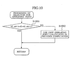
- step S1001 the operation is executed to make comparison between the target gear shift stage tG_old in the previous computing period and the target gear shift stage tG in the current computing period.
- discrimination is made as to whether tG is changed relative to tG_old, i.e. whether the gear shift occurs from a high speed gear ratio to a low speed gear ratio or from the low speed gear ratio to the high speed gear ratio.
- step S1001 when it is discriminated that tG is changed relative to tG_old , i.e. when the gear shift occurs from the high speed gear ratio to the low speed gear ratio or from the low speed gear ratio to the high speed gear ratio in a sequence, the operation is terminated.
- step S1001 when it is discriminated that tG is not changed relative to tG_old , i.e. when the gear shift does not occur from the high speed gear ratio to the low speed gear ratio or from the low speed gear ratio to the high speed gear ratio in the sequence, the operation proceeds to step S1002 where the target unit operating point is assigned to the unit operating point that is calculated in the previous computation.
- step S407 to realize the target unit operating point of Fig. 4 is described below with reference to a flow chart of Fig. 11 .
- step S1101 the amount of fuel injection, the throttle opening degree and the ignition timing are regulated to cause the internal combustion engine 1 to produce the output torque that is equal to the target engine torque tTe [Nm].
- step S1102 the motor 3 is vector controlled to produce the output torque that is equal to the target motor torque tTm [Nm].
- step S1103 the gear shift stage of the stepped power transmission 4 is shifted to the target gear shift stage tG .
- step S1104 the clutch 2 is controlled for engagement or disengagement in dependence on the preset value of the clutch engagement flag Fc.
- the operation may be executed along with the flow chart of Fig. 4 by replacing the running efficiency with a proportion of a mass of ingredients, in terms of the drive power rate required for driving the vehicle, exhausted by the engine in order to provide such drive power rate while the ingredients are limited from being exhausted.
Landscapes
- Engineering & Computer Science (AREA)
- Transportation (AREA)
- Mechanical Engineering (AREA)
- Chemical & Material Sciences (AREA)
- Combustion & Propulsion (AREA)
- Power Engineering (AREA)
- Automation & Control Theory (AREA)
- Life Sciences & Earth Sciences (AREA)
- Sustainable Development (AREA)
- Sustainable Energy (AREA)
- Human Computer Interaction (AREA)
- Electric Propulsion And Braking For Vehicles (AREA)
- Hybrid Electric Vehicles (AREA)
- Control Of Driving Devices And Active Controlling Of Vehicle (AREA)
- Control Of Vehicle Engines Or Engines For Specific Uses (AREA)
- Control Of Transmission Device (AREA)
Description
- The present invention relates to a control device and control method for a hybrid vehicle according to the preamble portion of
claim - An example of a related art hybrid vehicle is disclosed in
US Patent Application Publication Laid-open No. 2002-0062183A1 . With such a related art structure, the hybrid vehicle includes an internal combustion engine, a motor, an electric storage device and a power transmission to form a so-called hybrid vehicle in which at least one of drive power outputs of the internal combustion engine and the motor is transmitted via the power transmission to an output shaft thereof. In such a hybrid vehicle, a running mode and an operating point of a unit (the internal combustion engine, the motor and the power transmission) are determined such that the running efficiency (indicative of a proportion of a fuel flow rate, in terms of a drive power rate required for driving the vehicle, required for providing such power rate) is equal to a target value. - In such a concept, a target running efficiency is determined such that the higher the SOC value indicative of a remaining charged state of the electric storage device, the higher will be the target running efficiency. This results in a condition where the unit operating point is controlled such that as the SOC value remains at a high level, the electric storage device is charged only at the high running efficiency whereas when the SOC value remains at the low level, charging of the electric storage device is effectuated even at the low running efficiency. For this reason, it is possible to execute a control so as to permit the SOC value to be varied within an available range and to properly provide a given physical value, such as an exhaust gas flow rate and fuel consumption rate, related to the internal combustion engine.
- In the related art practice set forth above, operating points of the internal combustion engine to be used during a travel of the vehicle are compared between a case in which the power transmission includes an infinitely variable power transmission, such as a CVT, and a case in which the power transmission includes a stepped power transmission.
- An example of a structure, which employs the infinitely variable power transmission, is shown in
Fig. 1 in which a hybrid vehicle is structured with aninternal combustion engine 21, aclutch 22, amotor 23, the infinitelyvariable power transmission 24, agear reduction unit 25, agear differential 26 anddrive wheels 27. With such a vehicle, the presence of the infinitelyvariable power transmission 24 located for transmitting a drive power output of either one of theinternal combustion engine 21 and themotor 23 or drive power outputs of both the engine and the motor to thedrive wheels 27 enables an operating point of the internal combustion engine during running of the vehicle to be freely selected from an operating point tracing an equivalent power rate line that satisfies a drive power rate. Such a hybrid vehicle takes an advantage of the freedom of selecting the operating point while an attempt is made to control the operating point of the internal combustion engine to trace an α line for thereby providing an improved fuel consumption. - In contrast, with an alternative structure in which the infinitely variable power transmission 24 (inclusive of a
hydraulic device 28, amotor 29 and an inverter 31) ofFig. 1 is replaced with the stepped power transmission, since the operating point of the internal combustion engine is determined on the basis of a rotational speed of the internal combustion engine during the running condition, a vehicle speed and respective gear shift stages, the operating point of the internal combustion engine is forced to be selected from an intersecting point between the equivalent power rate line, that satisfies the drive power rate, and the rotational speed that can be taken out for each gear shift stage.Fig. 2 shows the operating points, encircled with○, of the internal combustion engine and the stepped power transmission that satisfy the drive power rate shown in a dotted line. Also shown by a thin solid line inFig. 2 is an equivalent running efficiency curve. In order for the improved fuel consumption to be provided with such a vehicle, the gear shift stage comes to be selected such that the operating point of the internal combustion engine becomes the high efficiency, with the freedom in selecting the operating point becoming smaller than that of the infinitely variable power transmission. Further, in an event that the internal combustion engine provides the power rate beyond the drive power rate with an excess of the power rate causing an electric power output to be produced and charged into the electric storage device, since the rotational speed is similarly determined with the vehicle speed and only the resulting torque output is regulated to increase the power rate of the internal combustion engine, the freedom of selecting the operating point becomes small. Thick solid lines inFig. 2 show the operating points taken out for respective gear shift stages. -
EP 0 759 370 A2claim - Thus, since no consideration is made for a difference in the operating points of the internal combustion engine in the case of the power transmission composed of the infinity variable type/stepped type structures, an issue arises in that the related art practice can not sufficiently comply with a requirement for selecting the gear shift stage and calculating the unit operating point.
- Further, when calculating the unit operating point that forms the target running efficiency, a difficulty is encountered in that the gear shift happens to occur even in the absence of variation in drive power demanded by a driver and the gear shift doe not occur from a high speed gear ratio to a low speed gear ratio or from the low speed gear ratio to the high speed gear ratio, with a resultant situation to give a different feeling touch to the driver.
- With the above view in mind, the present invention has an object to provide a control device and control method for a hybrid vehicle in which at least one of drive power outputs of an internal combustion engine and a motor is connected through a stepped power transmission to an output shaft thereof and which enables a target unit operating point, satisfying a target running efficiency, to be realized for effectively eliminating the amount of fuel required for entire running and the amount of exhaust ingredients to be limited.
- It is another object of the present invention to provide a control device and control method for a hybrid vehicle in which at least one of drive power outputs of an internal combustion engine and a motor is connected through a stepped power transmission to an output shaft thereof and which is able to alleviate a different feeling touch to be given to a driver due to a variation in a rotational speed of the internal combustion engine during a gear shift.
- The solution of these objects is achieved by the combination of features of
claim -
-
Fig. 1 is a structural view of a control device for a hybrid vehicle involving an infinitely variable power transmission. -
Fig. 2 is a view for illustrating operating points of an internal combustion engine when using a stepped power transmission. -
Fig. 3 is a structural view of an embodiment of the control device for the hybrid vehicle according to the present invention. -
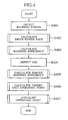
Fig. 4 is a schematic flowchart for illustrating a brief operation of the embodiment. -
Fig. 5 is a detailed flowchart of the embodiment. -
Fig. 6 is a detailed flowchart of the embodiment. -
Fig. 7 is a detailed flowchart of the embodiment. -
Fig. 8 is a detailed flowchart of the embodiment. -
Fig. 9 is a detailed flowchart of the embodiment. -
Fig. 10 is a detailed flowchart of the embodiment. -
Fig. 11 is a detailed flowchart of the embodiment. -
Fig. 12 is an example of a map table for use in the embodiment. -
Fig. 13 is an example of a map table for use in the embodiment. - Now, an embodiment according to the present invention will be described below with reference to the drawings.
-
Fig. 3 is a system structural view for illustrating a structure of an embodiment of a control device for a hybrid vehicle according to he present invention in compliance with the invention defined inclaim 1. InFig. 3 , a thick solid line designates a power transmission path, a dotted line designates an electric power line, and a thin solid line designates a control wiring. - The presently filed embodiment is explained in conjunction with a vehicle including a power train structured with an
internal combustion engine 1, aclutch 2, a motor 3, astepped power transmission 4, a gear reduction unit 5, a differential unit 6 anddrive wheels 7. An output shaft of theinternal combustion engine 1 is connected to an input shaft of theclutch 2, an output shaft of theclutch 2 is connected to an input of the motor 3, and an output shaft of the motor 3 is connected to an input shaft of thestepped power transmission 4. - The
internal combustion engine 1, theclutch 2, the motor 3 and thestepped power transmission 4 are conveniently referred to as adrive power unit 11 hereinafter, of which operative point is controlled with the control device of the hybrid vehicle (simply referred to as the control device hereinafter). - The
clutch 2 is controlled for engagement/disengagement with thecontrol device 12, and during engagement of theclutch 2, both theinternal combustion engine 1 and the motor 3 form a propulsion source of the vehicle whereas during disengagement of theclutch 2, only the motor 3 forms the propulsion source. The motor 3 is driven with an inverter 8. - The inverter 8 is connected to an
electric storage device 10 and operative to convert an alternating power output, generated by the motor 3 during a regenerative mode, to a direct power output which is charged into theelectric storage device 10 while during a propelling mode, converting the direct power output of the electric storage unit device to the alternating power output which is supplied to the motor 3 in response to a torque command delivered from thecontrol device 12 to provide an assisted drive power. Theelectric storage device 10 may be structured with a variety of batteries such as a lithium ion battery, a nickel hydrogen battery and a lead battery or a so-called capacitor such as an electric double layered capacitor. - While, in the presently filed embodiment, the
stepped power transmission 4 is described below as including a four speed power transmission, the present invention similarly has an advantage even in a case where the other type of stepped power transmission is utilized. - The
control device 12 is applied with a physical quantity, delivered from sensors which are not shown, indicative of a vehicle status such as an accelerator displacement value, a throttle opening degree, an engine speed, a vehicle speed, a motor drive current, a motor speed, an accessory load and a temperature of the electric storage device, or a converted quantity corresponding to the physical quantity. Also, thecontrol device 12 is responsive to these inputs and produces command signals to be delivered to theinternal combustion engine 1, theclutch 2, the motor 3, thestepped power transmission 4 and the inverter 8. - The
control device 12 is comprised of a state ofcharge detecting unit 13 which detects a state of charge (SOC) of theelectric storage device 10 indicative of a remaining charged capacity thereof, a target runningefficiency calculation unit 14 which serves as a means for calculating a target value of a running efficiency, which forms a rate of a given physical quantity in terms of a drive power rate required for driving the vehicle, such that the larger the SOC detected value, the smaller will be the target value, a target unit operatingpoint calculation unit 15 which calculates a target value of a unit operating point, that forms the target running efficiency set forth above, on the basis of operating points of thedrive power unit 11 in which the power rate generated by theinternal combustion engine 1 is adjusted at the highest running efficiency, and a target operatingpoint actualizing device 16 which controls such that thedrive power unit 11 operates at the target unit operating point previously mentioned. - Here, the operating point of the
drive power unit 11 which thecontrol device 12 controls is represented with a target engine torque tNe[Nm] which is to be generated by theinternal combustion engine 1, a target motor torque tTm[Nm], a target gear shift stage tG representing a gear shift stage which thestepped power transmission 4 enables a gear shift, and a clutch engagement flag Fc indicative of either one of engagement/disengagement of theclutch 2. - In the presently filed embodiment, though not intended to limit the invention to a particular configuration, the
control device 12 is realized using software control of a microcomputer. - Now, an overall control flow of the
control device 12 is described below with reference to a schematic flow chart ofFig. 4 . In the following description, the running efficiency is defined in terms of the drive power rate required for drive of the vehicle and assigned to be a proportion of the amount of fuel to be consumed for providing such a drive power rate, and a unit of the running efficiency is assigned as [cc/j](Claim 2). Also, [*] designates a multiplication symbol. - First, in step S401, the operation is executed to detect signals, indicative of the vehicle status, such as the accelerator pedal displacement value θa [deg] and the vehicle speed vsp [km/h].
- In step S402, the drive power rate tPd [W] required by a driver is calculated from the accelerator pedal displacement value θa [deg] and the vehicle speed vsp [km/h].
- In step S403, the operation is executed to calculate the running efficiency Vn that enables the power rate of the internal combustion engine to satisfy the drive power rate tPD [W] with no excess and shortage.
- In step S404, the SOC is detected. More specifically, the SOC detected value [%] is detected by obtaining the electric power output, which is delivered to or from the electric storage device, from a voltage occasionally appearing at terminals and by integrating the voltage with time. The SOC detected value [%] is assigned such that a full charged state of the
electric storage unit 10 is represented with 100 [%]. - In step S405, the target running efficiency is calculated on the basis of the SOC detected value.
- In step S406, the operation is executed to calculate the operating point of the power drive unit 11 (the
internal combustion engine 1, theclutch 2, the motor 3 and the stepped power transmission 4) that actualizes a determined operating mode. - In step S407, the
power drive unit 11 is controlled so as to realize the calculated operating point. - Details of the above steps are described below with reference to a detailed flow chart of
Figs. 5 to 11 . -
Fig. 5 is a detailed flow chart illustrating a detailed operation of step S402 for calculating the drive power rate ofFig. 4 . - In step S501, operation is executed to calculate the target drive torque tTD [Nm] by retrieving a map of MAPttd (vsp, θa) on the basis of the vehicle speed vsp [km/h] and the accelerator pedal displacement value θa [deg]. The target drive torque tTD [Nm] represents a target value of an output toque of the stepped
power transmission 4.Fig. 12 shows an example of MAPttd (vsp, θa) of the target drive torque. - In step S502, the drive power rate tPd [W] is calculated using a formula (1) on the basis of the target drive torque tTD [Nm] and the vehicle speed vsp [km/h]. Also, a symbol r in the formula (1) designates a tire's effective radius [m], and a symbol Gf represents a gear reduction ratio of the gear reduction unit 5.

- Here, the drive power rate tPd [W] may includes a value added with a power rate required for operating accessory units. In such a case, the running efficiency, which is calculated in step S403 (see
Fig. 4 ), is an actual value which reflects the electric power consumption of the accessory units, resulting in a further decrease in the running efficiency. - Next, a detailed operation of step S403 for calculating the running efficiency shown in
Fig. 4 is illustrated in a detailed flow chart ofFig. 6 . - In step S601, the operation is executed to calculate the torque Te(i)[Nm], that is the operating point of the internal combustion engine which satisfies the target drive power rate tPd [W], and the rotational speed Ne (i) [rad/s] (I = 1∼n) using a formula (2) and a formula (3), respectively. Here, the torque Te (i) [Nm] and the rotational speed Ne (i) [rad/s] represent the torque and the rotational speed, respectively, appearing when the
clutch 2 is held in engagement either with no provision of the assisted drive from the motor 3 or with no regenerative power generation of the motor 3. Also, a symbol i designates a gear stage of the stepped power transmission, a symbol G(i) designates a reduction ratio of the gear stage i, and a symbol n designates a value (in the presently filed embodiment, n = 4) of the highest gear stage.

- In step S602, the operation is executed to calculate the fuel consumption rate Fuel (i) [cc/s] of the internal combustion engine in case of using various gear reduction stages by retrieving the map of MAPfuel (Te(i), Ne(i)) (i=1 ∼ n).
Fig. 13 shows an example of the map MAPfuel of fuel consumption rate calculation result of the internal combustion engine. A value of this map represents the fuel consumption rate obtained through preliminary experimental tests. - In step S603, the operation is executed to select the smallest value of i among all the fuel consumption rates Fuel (i) of the internal combustion engine, with i being assigned as J.
- In step S604, the operation is executed to calculate the running efficiency Vn [cc/J], in a formula (4), to meet the drive power rate tPd [W] using the internal combustion engine.

- Subsequently, a detailed operation of step S405 for determining the target running efficiency of
Fig. 4 is described below with reference to a detailed flow chart ofFig. 7 . - In step S701, retrieving a table of TABLEtvd (SOC) allows the target running efficiency tVd [cc/s] to be calculated based on the SOC detected value of SOC [%]. The TABLEtvd (SOC) is determined to have the running efficiency with the maximum value, which the internal combustion engine is able to provide, at an upper limit value (for instance, SOC = 80 [%]) of an SCO available range, and determined to have the running efficiency with the maximum value in a range of the running efficiency in which discharging of the power output is disenabled at all times without relying on the running condition at a low limit value (for instance, SOC = 30 [%]).
- Here, the running efficiencies, that correspond to the upper and lower limit values of the SOC available range, may be determined by obtaining the running efficiencies in terms of all possible combinations between the drive power rate tPd and the power rate of the internal combustion engine which can be undertaken. Further, in a range beyond the upper and lower limits of the SOC available range, the target running efficiencies in terms of all the SOC values may be determined by implementing a linear complimenting based on correlated values.
- Next, the operation of step S406 for calculating the drive power unit operating point that satisfies the target running efficiency of
Fig. 4 is described in detail using a flow chart ofFig. 8 . - In step S801, the operation is executed to store the target engine torque tNe [Nm], the target motor torque tTm [Nm], the target gear shift stage tG and the clutch engagement flag Fc, which form the drive power unit operating points calculated in the previous computation.
- In step S802, the operation is executed to compare a large or small relationship between the running efficiency Vn [cc/J] and the target running efficiency tVd [cc/J].
- In step S802, in the case of tVd>Vn, the operation proceeds to step S803 where the operation is executed to compare the large or small relationship between the drive power rate tPd [W] and the power rate Pmin [W] of the internal combustion engine with the running efficiency remaining in a minimal value.
- In step S803, in the case of tPd<Pmin, the operation proceeds to steps S804 to S806 where the drive power unit operating points during a motor propelling mode are calculated.
- In step S804, retrieving the map of MAPttm(vsp, tPd) allows the target motor torque tTm [Nm] to be calculated on the basis of the vehicle speed vsp [km/h] and the drive power rate tPd [W]. The map of AMPttm(vsp, tPd) is formed, by calculating the motor torque values, satisfying the drive power rate tPd [W] in terms of the vehicle speed vsp [km/h], for respective gear shift stages on the basis of an energy conversion efficiency of the motor, with a value correlated with the motor torque that satisfies the drive power rate tPd [W] with a minimal amount of electric power output.
- In step S805, retrieving the map of MAPtg(vsp, tPd) allows the target gear shift stage tG to be calculated on the basis of the vehicle speed vsp [km/h] and the drive power rate tPd [W]. The map of MAPtg(vsp, tPd) is formed with a value correlated with the gear shift stage used when calculating the target motor torque tTm [Nm] using the map of MAPttm(vsp, tPd).
- In step S806, the clutch engagement flag is set to a logic level of "0". This is meant that the clutch remains disengaged.
- In step S803, in the absence of tPd<Pmin, the operation proceeds to steps S807 to S810 where the operation is executed to calculate the unit operating point during an assist running mode (running status in which the
clutch 2 is brought into engagement to allow a combined drive power between theinternal combustion engine 1 and the motor 3 to be provided to propel the vehicle). - In step S807, retrieving the map of MAPtte3(vsp, tVd) allows the target engine torque tTe [Nm] to be calculated on the basis of the vehicle speed vsp [km/h] and the target running efficiency tVd [cc/J]. The map of MAPtte3(vsp, tVd) is formed with a value of the unit operating point correlated with the torque output of the internal combustion engine, by which the maximum engine power rate satisfying the target running efficiency tVd [cc/J] is provided, among the unit operating points at which the power rate provided by the internal combustion engine is utilized at the running efficiency with the maximum value.
- In step S808, the map of MAPttm3(vsp, tPd, tVd) is formed with a value correlated with the motor torque calculated to compliment the drive power rate tPd [W], on the basis of the vehicle speed vsp [km/h], the target running efficiency tVd [cc/J] and the drive power rate tPd [W], using the operating point of the internal combustion engine calculated in step S807.
- In step S809, retrieving the map of MAPtg3 (vsp, tVd) allows the target gear shift stage tG to be calculated on the basis of the vehicle speed vsp [km/h] and the target running efficiency tVd [cc/J]. The map of MAPtg3 (vsp, tVd) is formed with a value correlated with the gear shift stage used when calculating the target engine torque tTe [Nm] using the map of MAPtte3(vsp, tVd).
- In step S810, the clutch engagement flag is set to a logic level of "1". This is meant that the clutch remains engaged.
- In step S802, in the absence of tVd>Vn, the operation proceeds to steps S811 to S814 where the operations are executed to calculate the unit operating points to be used during a direct drive running mode (a running mode in which the drive power rate is provided only with the power rate of the internal combustion engine 1) and a combined drive mode, inclusive of the direct drive running and chargeable running state in combination, (i.e. a running mode in which the
internal combustion engine 1 provides the power rate that is in excess of the drive power rate, with the excess drive power being utilized to drive the motor 3 as the electric power generator to produce the electric power output which is converted to the direct current power output to be charged to the electric storage device 10). - In step S811, retrieving the map of MAPtte2 (vsp, tPd, tVd) allows the target engine torque tTe [Nm] to be calculated on the basis of the vehicle speed vsp [km/h], the target running efficiency tVd [cc/J] and the drive power rate tPd [W]. The map of MAtte2 (vsp, tPd, tVd) is formed with a value of the unit operating point correlated with the torque output of the internal combustion engine, by which the maximum engine power rate satisfying the target running efficiency tVd [cc/J] is provided, among the unit operating points at which the power rate provided by the internal combustion engine is utilized at the running efficiency with the maximum value.
- In step S812, retrieving the map of MAPttm2 (vsp, tPd, tVd) allows the target motor torque tTm [Nm] to be calculated on the basis of the vehicle speed vsp [km/h], the target running efficiency tVd [cc/J] and the drive power rate tPd [W]. The map of MAPttm2 (vsp, tPd, tVd) is formed with a value of the operating point correlated with the output torque of the motor among the unit operating points when calculating the map of MAPtte2 (vsp, tPd, tVd) used in step S811.
- In step S813, retrieving the map of MAPtg2(vsp, tPd, tVd) allows the target gear shift stage tG to be calculated on the basis of the vehicle speed vsp [km/h], the target running efficiency tVd [cc/J] and the drive power rate tPd [W]. The map of MAPtg2 (vsp, tPd, tVd) is formed with a value correlated with the gear shift stage among the unit operating point when calculating the map of MAPtte2 (vsp, tPd, tVd) used in step S811.
- In step S814, the clutch engagement flag Fc is set to a logic level of "1" (in the engaged state).
- In subsequent step S815, the operation for selection of the operating points is executed, thereby completing the operation for the calculation of the target unit operating point, and the operation returns to the initial step. The operating point selecting operation is implemented to address an occurrence of a different feeling touch to be given to the driver when used the target value of the unit operating points calculated in the control flows so far. This operation is described below.
- A detail of the operating point selecting operation, that is defined in Claims 5, 6, is described with reference to a flow chart of
Fig. 9 . - In step S901, the operation is executed to make comparison between the drive power rate tPd_old [W] appearing in a previous calculation period and the drive power rate tPd [W] appearing in the current calculation period.
- In step S901, if it is discriminated that tPd_old ≒ tPd, the operation proceeds to step S910.
- In step S902, if it is not discriminated that tPd_old ≒ tPd, a variable is set to a logic level of "1". This variable "1' represents that a future prediction of the target unit operating point is implemented after an elapse of k seconds from the current time.
- In step S903, the operation is executed to make comparison for a large or small relationship between the variable k and a constant m indicative of a given time interval. This constant m represents that the prediction of the target unit operating point is implemented after an elapse of a time interval of k seconds from the current time. For instance, when setting the constant m to m = 10, the target unit operating point comes to be predicted for 10 seconds.
- In step S902, in the case of k≦m, the operation proceeds to step S904 in which an SOC transition of SOCe [k] after k seconds is predicted. The SOCe [k] is calculated in the following formula (5).

- Also, effBat represents a battery charging efficiency.

- In succeeding step S905, the operation is executed to predict the target running efficiency of tVde [cc/J] appearing from the current time until k seconds. This prediction is performed by retrieving the table of SOCe [k] utilizing the table of TABLEtvd (SOC) used in step S40t (see
Fig. 4 ) for calculating the target running efficiency. - In step S906, the unit operating point satisfying the target running efficiency of tVde [cc/J] is predicted. In this step, the operation is executed in the same manner as those of flow charts in steps S801 to 814 of
Fig. 8 . - In step S907, the variable k is increased by a value of 1, with the operation being branched to step S903.
- In the absence of k ≦m in step S903, the operation proceeds to step S908 in which discrimination is made as to whether the target gear shift stage tGe [k] (k = 1···m) until m seconds is equal to the target gear shift stage tG.
- In step S908, if it is discriminated that the target gear shift stage tGe [k] (k = 1···m) until m seconds is equal to the target gear shift stage tG, the operation proceeds to step S910.
- In step S908, if it is discriminated that the target gear shift stage tGe [k] (k = 1···m) until m seconds is not equal to the target gear shift stage tG, the operation proceeds to step S909 in which the target unit operating point is assigned to the unit operating point calculated in the previous computation.
- In step S910, the drive power rate tPd [W] is assigned to the drive power rate tPd_old [W] appearing in the previous computation.
- Next, a detail of the operating point selecting operation, defined in
Claim 7, is described below with reference to a flow chart ofFig. 10 . - In step S1001, the operation is executed to make comparison between the target gear shift stage tG_old in the previous computing period and the target gear shift stage tG in the current computing period. Here, discrimination is made as to whether tG is changed relative to tG_old, i.e. whether the gear shift occurs from a high speed gear ratio to a low speed gear ratio or from the low speed gear ratio to the high speed gear ratio.
- In step S1001, when it is discriminated that tG is changed relative to tG_old, i.e. when the gear shift occurs from the high speed gear ratio to the low speed gear ratio or from the low speed gear ratio to the high speed gear ratio in a sequence, the operation is terminated.
- In step S1001, when it is discriminated that tG is not changed relative to tG_old, i.e. when the gear shift does not occur from the high speed gear ratio to the low speed gear ratio or from the low speed gear ratio to the high speed gear ratio in the sequence, the operation proceeds to step S1002 where the target unit operating point is assigned to the unit operating point that is calculated in the previous computation.
- Next, a detail of operations in step S407 to realize the target unit operating point of
Fig. 4 is described below with reference to a flow chart ofFig. 11 . - In step S1101, the amount of fuel injection, the throttle opening degree and the ignition timing are regulated to cause the
internal combustion engine 1 to produce the output torque that is equal to the target engine torque tTe [Nm]. - In step S1102, the motor 3 is vector controlled to produce the output torque that is equal to the target motor torque tTm [Nm]. In step S1103, the gear shift stage of the stepped
power transmission 4 is shifted to the target gear shift stage tG. In step S1104, theclutch 2 is controlled for engagement or disengagement in dependence on the preset value of the clutch engagement flag Fc. - As an example for realizing Claim 3, the operation may be executed along with the flow chart of
Fig. 4 by replacing the running efficiency with a proportion of a mass of ingredients, in terms of the drive power rate required for driving the vehicle, exhausted by the engine in order to provide such drive power rate while the ingredients are limited from being exhausted. - A method of preparing various maps utilized in the embodiment is described hereinafter.
- [A] A Method of Preparing the Target Motor Torque Map of MAPttm (vsp,tPd) and the Target Gear Shift Stage Map of MAPtg (vsp,tPd).
- (1) The motor speeds Nm (i) are calculated for arbitrary vehicle speeds vsp when using respective gear shift stages i.
- (2) An arbitrary drive power rate tPd is divided by Nm (i) to derive the motor torque Tm (i).
- (3) Motor power consumptions Pm (i) when assigning the motor operating points to Nm (i), Tm (i) are calculated. During calculation, the energy conversion efficiency of the motor may be taken into consideration.
- (4) The gear shift stage i, which Pm (i) takes a minimal value, is assigned to the target gear shift stage tG for vsp, tPd.
- (5) Values of Tm (tG) are stored as the target motor torques tTm in compliance with vsp, tPd to provide the target motor torque map of MAPttm (vsp,tPd).
- (6) Values of tG are stored in compliance with vsp, tPd to provide the target gear shift stage map of MAPtg (vsp, tPd).
- [B] A Method of Preparing the Target Engine Torque Map of MAPtte3 (vsp, tVd), the Target Gear Shift Stage of MAPtg3 (vsp, tVd) and the Target Motor Torque Map of MAPttm3 (vsp, tVd, tPd).
- (1) The engine rotational speeds Ne (i) are calculated for arbitrary vehicle speeds vsp when using respective gear shift stages i .
- (2) The engine power outputs (engine power rate) of Pe (i, k) and the fuel consumption rates of F (i, k) are calculated in terms of various engine torques Te (k) when permitting the engine operating points to be assigned to Ne (i), Te (k), provided that k = 1, 2, 3···m, Te (l) = minimal engine torque, Te (k) = engine torque at the k-th number, and Te (m) = maximum engine torque.
- (3) F (i, k) is divided by Pe (i, k), calculating the running efficiency V (i, k).
- (4) The operation is implemented to extract a combination of i and k that provides V (i, k) = tVd in terms of an arbitrary target running efficiency tVd. In an existence of a plurality of combinations, a combination whose Pe (i, k) has the maximum value is extracted (with i, k of the extracted combination being assigned to I, K hereinafter).
- (5) I is assigned to the target gear shift stage tG for vsp, tVd.
- (6) A value of Te (K) is stored as the target engine torque tTe in compliance with vsp, tVd to provide the target engine torque map of MAPtte3 (vsp, tVd).
- (7) tG is stored in compliance with vsp, tVd to provide the target gear shift stage map of MAPtg3 (vsp, tVd).
- (8) Subtracting Pe (I, K) from tPd for an arbitrary tPd provides the power output (power rate) Pma to be assisted with the motor.
- (9) Dividing Pma with Ne (I) (= engine speed = motor speed) allows the target motor torque tTm to be calculated.
- (10) Storing tTm in compliance with vsp, tVd, tPd provides the target motor torque map of MAPttm3 (vsp, tVd, tPd).
- [C] A Method of Preparing the Target Engine Torque Map of MAPtte2 (vsp, tPd, tVd), the Target Gear Shift Stage Map of MAPtg2 (vsp, tPd, tVd) and the Target Motor Torque Map of MAPttm2 (vsp, tVd, tPd).
- (1) The engine rotational speeds Ne (i) are calculated for arbitrary vehicle speeds vsp when using respective gear shift stages i.
- (2) The engine power outputs (engine power rate) of Pe (i, k) and the fuel consumption rates of F (i, k) are calculated in terms of various engine torques Te (k) when permitting the engine operating points to be assigned to Ne (i), Te (k), provided that k = 1, 2, 3···m, Te (l) = minimal engine torque, Te (k) = engine torque at the k-th number, and Te (m) = maximum engine torque.
- (3) Subtracting the drive power rate of tPd from Pe (i, k) allows an excess power output (= charging electric power output) of Per (i, k) to be calculated.
- (4) Multiply Per (i, k) by the charging efficiency and discharging efficiency of the battery to give an effective motor power output Pme (i, k) (power output available as a future motor power output among the excess power output of Per).
- (5) Divide F (i, k) by a sum of tPd and Pme (i, k) to calculate the running efficiency V (i, k).
- (6) Implement operation to extract a combination of i and k that provides V (i, k) = tVd in terms of an arbitrary target running efficiency tVd. In an existence of a plurality of combinations, extract a combination whose Pe (i, k) has the maximum value (with i, k of the extracted combination being assigned to I, K hereinafter).
- (7) Assign I to the target gear shift stage tG for vsp, tVd.
- (8) Stote a value of Te (K) as the target engine torque tTe in compliance with vsp,tPd, tVd to provide the target engine torque map of MAPtte2 (vsp, tPd, tVd).
- (9) Store a value of tG in compliance with vsp, tVd, tPd to provides the target gear shift stage map of MAPtg2 (vsp, tVd, tPd).
- (10) Divide the excess power output Per (I, K) with Ne (I) (= engine speed = motor speed) to calculate the target motor torque tTm.
- (11) Store tTm in compliance with vsp, tVd, tPd to obtain the target motor torque map of MAPtt23 (vsp, tVd, tPd).
- Although the present invention has been described above by reference to certain embodiments of the present invention, the invention is not limited to the embodiments described above and modification occur to those skilled in the art, in light of the teachings. The scope of the present invention is defined with reference to the following claims.
Claims (4)
- A control device (12) for a hybrid vehicle, including a unit (11) having an internal combustion engine (1), a motor (3), a stepped power transmission (4) and an electric storage device (10) adapted to supply electric power output to the motor, wherein at least one of power outputs of the internal combustion engine and the motor is transmitted through the stepped power transmission to an output shaft thereof, the control device comprising:- a state of charge detecting section (13) detecting an SOC value indicative of a remaining charged capacity of the electric storage device;- a target running efficiency calculating section (14) calculating a target value of a running efficiency indicative of a proportion of a given physical quantity in terms of a drive power rate (tPd) required for driving the vehicle, in such a manner that the higher the SOC value, the smaller will be the target value to be calculated, wherein the physical quantity is a minimum value (Fuel [i] of fuel consumptions (Fuel [i] for i=1-4), determined by a torque and rotational speed of the internal combustion engine (1), for respective gear shift stages (i=1-4) of the stepped power transmission (14);- a target unit operating point calculating section (15) calculating a target value of a unit operating point, that forms the target running efficiency, from among operating points of the unit which cause the drive power rate provided by the internal combustion engine to be utilized at the running efficiency with the maximum efficiency, and therein calculating the target value of the unit operating point so as to interrupt a gear shift for a given time interval in the absence of variation in a demanded drive power; and- a target unit operating point actualizing section (16) controlling the unit such that the unit is operated at the target unit operating point,characterized in that- the target unit operating point calculating section (15) comprises:- a demanded drive power variation detecting section (S901) detecting variation in the demanded drive power output;- an SOC transition predicting section (S904) predicting an SOC transition in a case where in the absence of variation in the demanded drive power, it is assumed that the unit is operated for a given time interval using the preliminarily calculated target unit operating point; and- a target unit operating point predicting section (S906) predicting the target unit operating point based on the target running efficiency calculated on the basis of the predicted SOC transition;- wherein when an occurrence of the gear shift within the given time interval after prediction of the target unit operating point is predicted, the target unit operating point calculating section serves as a unit to cause the target unit operating point used in a previous calculation to be assigned to the target value of the unit operating point.
- The control device for the hybrid vehicle according to claim 1, further comprising:- a chargeable and dischargeable power output calculating section (S701) calculating a chargeable and dischargeable power output of the electric storage device and operative to serve as a unit to allow the unit operating point, that permit the electric storage device to be charged and discharged within a chargeable and dischargeable power output range, to be assigned to the target value of the unit operating point.
- The control device for the hybrid vehicle according to claim 1, wherein the target unit operating point calculating section (15) serves as a unit wherein when there is the absence of a transition in a gear shift stage from a low speed gear ratio to a high speed gear ratio or from the high speed gear ratio to the low speed gear ratio in a sequence when it is assumed that the unit is operated using the calculated target unit operating point, the target unit operating point used in a previous calculation is assigned to the target value of the unit operating point.
- A control method for a hybrid vehicle, including a unit (11) having an internal combustion engine (1), a motor (3), a stepped power transmission (4) and an electric storage device (10) adapted to supply electric power output to the motor, wherein at least one of power outputs of the internal combustion engine and the motor is transmitted through the stepped power transmission to an output shaft thereof, the control method comprising:- detecting an SOC value indicative of a remaining charged capacity of the electric storage device;- calculating a target value of a running efficiency indicative of a proportion of a given physical quantity in terms of a drive power rate required for driving the vehicle in such a manner that the higher the SOC value, the smaller will be the target value to be calculated, wherein the physical quantity is a minimum value (Fuel [i] of fuel consumptions (Fuel [i] for i=1-4), determined by a torque and rotational speed of the internal combustion engine (1), for respective gear shift stages (i=1-4) of the stepped power transmission (14);- calculating a target value of a unit operating point, that forms the target running efficiency, from among operating points of the unit which cause a power rate provided by the internal combustion engine to be utilized at the running efficiency with the maximum efficiency, and therein calculating the target value of the unit operating point so as to interrupt a gear shift for a given time interval in the absence of variation in a demanded drive power; and- controlling the unit in a way to actualize operation of the unit at the target unit operating point,characterized in that- the step of calculating the target value of the unit operating point, comprises:- detecting (S901) variation in the demanded drive power output;- predicting (S904) an SOC transition in a case where in the absence of variation in the demanded drive power, it is assumed that the unit is operated for a given time interval using the preliminarily calculated target unit operating point; and- predicting (S906) the target unit operating point based on the target running efficiency calculated on the basis of the predicted SOC transition;- wherein when an occurrence of the gear shift within the given time interval after prediction of the target unit operating point is predicted, the target unit operating point used in a previous calculation is assigned to the target value of the unit operating point.
Applications Claiming Priority (2)
| Application Number | Priority Date | Filing Date | Title |
|---|---|---|---|
| JP2001313836A JP3666438B2 (en) | 2001-10-11 | 2001-10-11 | Control device for hybrid vehicle |
| JP2001313836 | 2001-10-11 |
Publications (3)
| Publication Number | Publication Date |
|---|---|
| EP1302353A2 EP1302353A2 (en) | 2003-04-16 |
| EP1302353A3 EP1302353A3 (en) | 2004-03-10 |
| EP1302353B1 true EP1302353B1 (en) | 2009-08-26 |
Family
ID=19132244
Family Applications (1)
| Application Number | Title | Priority Date | Filing Date |
|---|---|---|---|
| EP02021102A Expired - Lifetime EP1302353B1 (en) | 2001-10-11 | 2002-09-23 | Control device and control method for hybrid vehicle |
Country Status (4)
| Country | Link |
|---|---|
| US (1) | US6629027B2 (en) |
| EP (1) | EP1302353B1 (en) |
| JP (1) | JP3666438B2 (en) |
| DE (1) | DE60233467D1 (en) |
Cited By (1)
| Publication number | Priority date | Publication date | Assignee | Title |
|---|---|---|---|---|
| CN103153740A (en) * | 2011-01-25 | 2013-06-12 | 日野自动车株式会社 | Control device, hybrid vehicle, control method, and program |
Families Citing this family (71)
| Publication number | Priority date | Publication date | Assignee | Title |
|---|---|---|---|---|
| EP1415837A1 (en) * | 2002-10-29 | 2004-05-06 | STMicroelectronics S.r.l. | Parallel configuration system for hybrid vehicles |
| DE10324573A1 (en) * | 2003-05-30 | 2004-12-16 | Daimlerchrysler Ag | Motor vehicle and electronic control device therefor |
| FR2857627B1 (en) * | 2003-07-18 | 2006-03-03 | Renault Sa | DEVICE FOR CONTROLLING THE OPERATION OF THE MOTOR PROPELLER GROUP OF A HYBRID VEHICLE |
| US6994360B2 (en) * | 2003-09-22 | 2006-02-07 | Ford Global Technologies, Llc | Controller and control method for a hybrid electric vehicle powertrain |
| US6876098B1 (en) * | 2003-09-25 | 2005-04-05 | The United States Of America As Represented By The Administrator Of The Environmental Protection Agency | Methods of operating a series hybrid vehicle |
| US6957137B2 (en) * | 2003-10-14 | 2005-10-18 | General Motors Corporation | Real-time operating parameter selection in a vehicular transmission |
| DE10353256B3 (en) * | 2003-11-14 | 2005-03-31 | Barske, Heiko, Dr. | Automobile hybrid drive system with common control of converter unit between electrical machine driven by IC engine and electrical energy store and clutches on input and output sides of electrical machine |
| US7653474B2 (en) * | 2004-05-14 | 2010-01-26 | Gm Global Technology Operations, Inc. | Method of determining engine output power in a hybrid electric vehicle |
| US7285869B2 (en) * | 2004-07-29 | 2007-10-23 | Ford Global Technologies, Llc | Method for estimating engine power in a hybrid electric vehicle powertrain |
| US7233128B2 (en) * | 2004-07-30 | 2007-06-19 | Ford Global Technologies, Llc | Calculation of state of charge offset using a closed integral method |
| DE102004044507A1 (en) * | 2004-09-15 | 2006-03-30 | Robert Bosch Gmbh | Method for operating a vehicle drive and apparatus for carrying out the method |
| US7351182B2 (en) * | 2004-10-27 | 2008-04-01 | Aisin Aw Co., Ltd. | Drive apparatus for hybrid vehicle and control method thereof |
| US7543454B2 (en) | 2005-03-14 | 2009-06-09 | Zero Emission Systems, Inc. | Method and auxiliary system for operating a comfort subsystem for a vehicle |
| US7600595B2 (en) * | 2005-03-14 | 2009-10-13 | Zero Emission Systems, Inc. | Electric traction |
| JP4265570B2 (en) * | 2005-05-10 | 2009-05-20 | トヨタ自動車株式会社 | Power output device, automobile equipped with the same, drive device, and control method for power output device |
| JP4549923B2 (en) | 2005-05-20 | 2010-09-22 | トヨタ自動車株式会社 | Load driving device and electric vehicle equipped with the same |
| US7370716B2 (en) * | 2005-06-01 | 2008-05-13 | Caterpillar Inc. | Motor/generator |
| JP4525919B2 (en) * | 2005-06-02 | 2010-08-18 | 株式会社デンソー | Power generation control device for internal combustion engine |
| WO2007043924A1 (en) * | 2005-10-14 | 2007-04-19 | Volvo Construction Equipment Ab | A working machine and a method for operating a working machine |
| DE102005051382A1 (en) * | 2005-10-27 | 2007-05-10 | Zf Friedrichshafen Ag | Hybrid drive and method for its operation |
| US11247564B2 (en) | 2005-11-17 | 2022-02-15 | Invently Automotive Inc. | Electric vehicle power management system |
| US11279233B2 (en) | 2005-11-17 | 2022-03-22 | Invently Automotive Inc. | Electric vehicle power management system |
| US11370302B2 (en) | 2005-11-17 | 2022-06-28 | Invently Automotive Inc. | Electric vehicle power management system |
| US11214144B2 (en) | 2005-11-17 | 2022-01-04 | Invently Automotive Inc. | Electric vehicle power management system |
| US11180025B2 (en) | 2005-11-17 | 2021-11-23 | Invently Automotive Inc. | Electric vehicle power management system |
| US11254211B2 (en) | 2005-11-17 | 2022-02-22 | Invently Automotive Inc. | Electric vehicle power management system |
| US11186173B2 (en) | 2005-11-17 | 2021-11-30 | Invently Automotive Inc. | Electric vehicle power management system |
| US11390165B2 (en) | 2005-11-17 | 2022-07-19 | Invently Automotive Inc. | Electric vehicle power management system |
| US11267338B2 (en) | 2005-11-17 | 2022-03-08 | Invently Automotive Inc. | Electric vehicle power management system |
| JP4215043B2 (en) * | 2005-11-17 | 2009-01-28 | トヨタ自動車株式会社 | POWER OUTPUT DEVICE, VEHICLE MOUNTING THE SAME, AND METHOD FOR CONTROLLING POWER OUTPUT DEVICE |
| US11345236B2 (en) | 2005-11-17 | 2022-05-31 | Invently Automotive Inc. | Electric vehicle power management system |
| US10882399B2 (en) | 2005-11-17 | 2021-01-05 | Invently Automotive Inc. | Electric vehicle power management system |
| US11230190B2 (en) | 2005-11-17 | 2022-01-25 | Invently Automotive Inc. | Electric vehicle power management system |
| DE102005057117A1 (en) * | 2005-11-30 | 2007-06-14 | Siemens Ag | Apparatus for detecting an electrical quantity of a rechargeable battery and method of manufacturing the same |
| US7921945B2 (en) | 2006-02-21 | 2011-04-12 | Clean Emissions Technologies, Inc. | Vehicular switching, including switching traction modes and shifting gears while in electric traction mode |
| US8565969B2 (en) | 2007-04-03 | 2013-10-22 | Clean Emissions Technologies, Inc. | Over the road/traction/cabin comfort retrofit |
| DE102006036443A1 (en) * | 2006-08-04 | 2008-02-07 | Robert Bosch Gmbh | Device for controlling a hybrid drive |
| FR2907744B1 (en) * | 2006-10-26 | 2009-05-08 | Renault Sas | METHOD AND DEVICE FOR CONTROLLING THE ELECTRICAL LOAD OF A BUFFER ELEMENT FOR INFINITELY VARIABLE TRANSMISSION. |
| US7921950B2 (en) | 2006-11-10 | 2011-04-12 | Clean Emissions Technologies, Inc. | Electric traction retrofit |
| US7967091B2 (en) * | 2006-11-16 | 2011-06-28 | Ford Global Technologies, Llc | Hybrid electric vehicle powertrain with engine start and transmission shift arbitration |
| US8234025B2 (en) * | 2006-11-28 | 2012-07-31 | GM Global Technology Operations LLC | Control system for a hybrid powertrain system |
| JP4379484B2 (en) * | 2007-04-06 | 2009-12-09 | 株式会社デンソー | Vehicle system |
| DE102007038585A1 (en) * | 2007-08-16 | 2009-03-19 | Zf Friedrichshafen Ag | Method for load point shift in hybrid operation in a parallel hybrid vehicle |
| KR100957144B1 (en) * | 2007-11-07 | 2010-05-11 | 현대자동차주식회사 | Vehicle generation control device and method |
| FR2927041B1 (en) * | 2008-02-01 | 2011-03-18 | Renault Sas | METHOD AND DEVICE FOR OPTIMIZING THE OPERATING POINT OF A HYBRID MOTORPROOFING UNIT WITH INFINITELY VARIABLE TRANSMISSION. |
| JP5314906B2 (en) * | 2008-02-29 | 2013-10-16 | ニチユ三菱フォークリフト株式会社 | Work vehicle control method and work vehicle |
| KR20140132775A (en) | 2008-03-19 | 2014-11-18 | 클린 에미션스 테크놀로지스, 인코포레이티드 | Electric traction system and method |
| US9758146B2 (en) | 2008-04-01 | 2017-09-12 | Clean Emissions Technologies, Inc. | Dual mode clutch pedal for vehicle |
| DE102008033481A1 (en) * | 2008-07-16 | 2010-01-21 | Bayerische Motoren Werke Aktiengesellschaft | Method for determining at least one operating state of a hybrid vehicle and hybrid vehicle |
| DE102008058809B4 (en) * | 2008-11-24 | 2017-11-30 | EMPA Eidgenössische Materialprüfungs-und Forschungsanstalt | Method for operating a drive unit of a vehicle and drive unit |
| DE102008060954B4 (en) * | 2008-12-06 | 2023-03-09 | Bayerische Motoren Werke Aktiengesellschaft | Method for regulating or controlling the state of charge of an electrical energy store of a hybrid vehicle |
| US20100156210A1 (en) * | 2008-12-19 | 2010-06-24 | Tai-Her Yang | Bidirectional unequal speed electric motor driven constant directional output system |
| CN101789755B (en) * | 2008-12-19 | 2015-05-20 | 杨泰和 | Bidirectional variable speed electric motor constant output drive system |
| US8143822B2 (en) * | 2008-12-19 | 2012-03-27 | Tai-Her Yang | Bidirectional unequal speed electric motor driven bidirectional output system |
| US8143823B2 (en) * | 2008-12-19 | 2012-03-27 | Tai-Her Yang | Bidirectional different speed ratio electric motor driving device with bidirectional input |
| US9631528B2 (en) | 2009-09-03 | 2017-04-25 | Clean Emissions Technologies, Inc. | Vehicle reduced emission deployment |
| CN101648562B (en) * | 2009-09-04 | 2012-10-24 | 奇瑞汽车股份有限公司 | Speed ratio control method of stepless speed changer of electric automobile |
| KR20110054135A (en) * | 2009-11-17 | 2011-05-25 | 현대자동차주식회사 | Soc band strategy for hev |
| US8463473B2 (en) * | 2010-01-10 | 2013-06-11 | Ford Global Technologies, Llc | Charge utilization control system and method |
| US8602141B2 (en) | 2010-04-05 | 2013-12-10 | Daimler Trucks North America Llc | Vehicle power system with fuel cell auxiliary power unit (APU) |
| US8831811B2 (en) * | 2010-04-05 | 2014-09-09 | Honda Motor Co., Ltd. | Control unit for hybrid vehicle |
| JP5739842B2 (en) | 2012-06-22 | 2015-06-24 | 日産自動車株式会社 | Vehicle drive device |
| CN102849062B (en) * | 2012-09-18 | 2015-10-14 | 中国第一汽车股份有限公司 | A kind of drived control method of stroke-increasing electric automobile |
| US9434378B2 (en) | 2014-12-23 | 2016-09-06 | Toyota Motor Engineering & Manufacturing North America, Inc. | System and method for improving the vehicle feel, fuel efficiency and performance of a hybrid vehicle |
| JP6065047B2 (en) * | 2015-04-24 | 2017-01-25 | 日産自動車株式会社 | Vehicle control apparatus and vehicle control method |
| KR101714247B1 (en) * | 2015-10-27 | 2017-03-08 | 현대자동차주식회사 | Apparatus and Method for controlling alternator variably |
| FR3072057B1 (en) * | 2017-10-05 | 2019-10-11 | Renault S.A.S | METHOD FOR CONTROLLING A MOTOR POWERTRAIN OF A MOTOR VEHICLE |
| CN109895758A (en) * | 2017-12-08 | 2019-06-18 | 郑州宇通客车股份有限公司 | A kind of hybrid electric vehicle engine torque control method, system and vehicle |
| US11654780B2 (en) | 2020-12-17 | 2023-05-23 | Consolidated Metco, Inc. | Vehicle electronic control unit and method |
| KR20230152458A (en) * | 2022-04-27 | 2023-11-03 | 현대자동차주식회사 | Hybrid electric vehicle and method controlling for the same |
| CN116394916B (en) * | 2023-04-03 | 2025-09-19 | 潍柴动力股份有限公司 | Gear shifting and charging control method and device for hybrid vehicle, vehicle and storage medium |
Family Cites Families (20)
| Publication number | Priority date | Publication date | Assignee | Title |
|---|---|---|---|---|
| DE4133013C2 (en) * | 1991-10-04 | 1995-11-30 | Mannesmann Ag | Non-track-bound vehicle with an electrodynamic converter |
| US5586613A (en) * | 1993-04-22 | 1996-12-24 | The Texas A&M University System | Electrically peaking hybrid system and method |
| JP3094745B2 (en) * | 1993-09-24 | 2000-10-03 | トヨタ自動車株式会社 | Hybrid vehicle power generation control device |
| JPH08289407A (en) * | 1995-02-13 | 1996-11-01 | Nippon Soken Inc | Power generation control device for hybrid vehicle |
| DE19505431B4 (en) * | 1995-02-17 | 2010-04-29 | Bayerische Motoren Werke Aktiengesellschaft | Power control system for motor vehicles with a plurality of power converting components |
| JP3171079B2 (en) * | 1995-07-24 | 2001-05-28 | トヨタ自動車株式会社 | Vehicle drive control device |
| JPH0998515A (en) * | 1995-07-25 | 1997-04-08 | Nippon Soken Inc | Hybrid vehicle engine control system |
| JP3409523B2 (en) * | 1995-08-02 | 2003-05-26 | アイシン・エィ・ダブリュ株式会社 | Control device for vehicle drive unit |
| JPH09224303A (en) * | 1996-02-16 | 1997-08-26 | Nippon Soken Inc | Vehicle control device for hybrid vehicle |
| US6018694A (en) * | 1996-07-30 | 2000-01-25 | Denso Corporation | Controller for hybrid vehicle |
| JP3401181B2 (en) * | 1998-02-17 | 2003-04-28 | トヨタ自動車株式会社 | Drive control device for hybrid vehicle |
| JPH11270668A (en) * | 1998-03-20 | 1999-10-05 | Nissan Motor Co Ltd | Drive control device for hybrid vehicle |
| JP3003675B2 (en) * | 1998-07-07 | 2000-01-31 | 株式会社デンソー | Control device for hybrid electric vehicle |
| JP3489449B2 (en) * | 1998-07-13 | 2004-01-19 | 日産自動車株式会社 | Drive control device for parallel hybrid vehicle |
| JP3536704B2 (en) * | 1999-02-17 | 2004-06-14 | 日産自動車株式会社 | Vehicle driving force control device |
| JP3395708B2 (en) * | 1999-04-27 | 2003-04-14 | 株式会社日立製作所 | Hybrid vehicle |
| JP3654048B2 (en) * | 1999-05-20 | 2005-06-02 | 日産自動車株式会社 | Drive control apparatus for hybrid vehicle |
| DE10049567B4 (en) * | 1999-10-08 | 2017-12-14 | Toyota Jidosha Kabushiki Kaisha | Vehicle control unit for controlling a four-wheel drive motor vehicle |
| JP2001146121A (en) * | 1999-11-19 | 2001-05-29 | Toyota Motor Corp | Control device for hybrid vehicle with transmission |
| JP3832237B2 (en) | 2000-09-22 | 2006-10-11 | 日産自動車株式会社 | Control device for hybrid vehicle |
-
2001
- 2001-10-11 JP JP2001313836A patent/JP3666438B2/en not_active Expired - Fee Related
-
2002
- 2002-09-23 EP EP02021102A patent/EP1302353B1/en not_active Expired - Lifetime
- 2002-09-23 DE DE60233467T patent/DE60233467D1/en not_active Expired - Lifetime
- 2002-10-02 US US10/261,488 patent/US6629027B2/en not_active Expired - Fee Related
Cited By (1)
| Publication number | Priority date | Publication date | Assignee | Title |
|---|---|---|---|---|
| CN103153740A (en) * | 2011-01-25 | 2013-06-12 | 日野自动车株式会社 | Control device, hybrid vehicle, control method, and program |
Also Published As
| Publication number | Publication date |
|---|---|
| US6629027B2 (en) | 2003-09-30 |
| EP1302353A3 (en) | 2004-03-10 |
| DE60233467D1 (en) | 2009-10-08 |
| JP2003118434A (en) | 2003-04-23 |
| EP1302353A2 (en) | 2003-04-16 |
| US20030074115A1 (en) | 2003-04-17 |
| JP3666438B2 (en) | 2005-06-29 |
Similar Documents
| Publication | Publication Date | Title |
|---|---|---|
| EP1302353B1 (en) | Control device and control method for hybrid vehicle | |
| JP4692646B2 (en) | Power source control device | |
| EP1276631B1 (en) | Hybrid vehicle control system and control method | |
| EP0962352B1 (en) | Drive power control device for hybrid vehicle | |
| KR102602227B1 (en) | Eco-friendly vehicle and method of providing charging amount guide | |
| US8571737B2 (en) | Hybrid vehicle and control method thereof | |
| US6173574B1 (en) | Hybrid electric vehicle control apparatus for maximizing vehicle engine operating efficiency | |
| JP5549726B2 (en) | Cruising range calculation device | |
| US7296648B2 (en) | Power control apparatus for hybrid vehicle | |
| EP0808735B1 (en) | Control system for hybrid vehicles | |
| CN101516703B (en) | Vehicle control device, vehicle control method | |
| EP2014529B1 (en) | An engine start control device and method for a hybrid vehicle | |
| US7565942B2 (en) | Vehicle drive control system and method | |
| RU2662378C1 (en) | Hybrid vehicle and hybrid vehicle control method | |
| EP1669236B1 (en) | Gearshift control system for hybrid-drive electric vehicle | |
| EP0759370A2 (en) | Hybrid vehiclee control with selection of drive mode according to energy conversion efficiency in electric drive | |
| US20100250042A1 (en) | Vehicle and method of controlling the vehicle | |
| CN102027653A (en) | Discharge control device for secondary battery | |
| WO2014167413A1 (en) | Hybrid vehicle | |
| JP2005120907A (en) | Shift control device for hybrid vehicle | |
| WO2019116585A1 (en) | Fuel economy display control method and fuel economy display control system | |
| JP2004019641A (en) | Hybrid powertrain control system for vehicles | |
| JPH08322108A (en) | Hybrid vehicle | |
| JP2017100469A (en) | Device for controlling hybrid vehicle | |
| JP2013129379A (en) | Control device of vehicle |
Legal Events
| Date | Code | Title | Description |
|---|---|---|---|
| PUAI | Public reference made under article 153(3) epc to a published international application that has entered the european phase |
Free format text: ORIGINAL CODE: 0009012 |
|
| 17P | Request for examination filed |
Effective date: 20020923 |
|
| AK | Designated contracting states |
Designated state(s): AT BE BG CH CY CZ DE DK EE ES FI FR GB GR IE IT LI LU MC NL PT SE SK TR |
|
| AX | Request for extension of the european patent |
Extension state: AL LT LV MK RO SI |
|
| PUAL | Search report despatched |
Free format text: ORIGINAL CODE: 0009013 |
|
| AK | Designated contracting states |
Kind code of ref document: A3 Designated state(s): AT BE BG CH CY CZ DE DK EE ES FI FR GB GR IE IT LI LU MC NL PT SE SK TR |
|
| AX | Request for extension of the european patent |
Extension state: AL LT LV MK RO SI |
|
| 17Q | First examination report despatched |
Effective date: 20041006 |
|
| AKX | Designation fees paid |
Designated state(s): DE FR GB |
|
| 17Q | First examination report despatched |
Effective date: 20041006 |
|
| GRAP | Despatch of communication of intention to grant a patent |
Free format text: ORIGINAL CODE: EPIDOSNIGR1 |
|
| RIC1 | Information provided on ipc code assigned before grant |
Ipc: B60K 6/48 20071001AFI20090326BHEP |
|
| GRAS | Grant fee paid |
Free format text: ORIGINAL CODE: EPIDOSNIGR3 |
|
| GRAA | (expected) grant |
Free format text: ORIGINAL CODE: 0009210 |
|
| AK | Designated contracting states |
Kind code of ref document: B1 Designated state(s): DE FR GB |
|
| REG | Reference to a national code |
Ref country code: GB Ref legal event code: FG4D |
|
| REF | Corresponds to: |
Ref document number: 60233467 Country of ref document: DE Date of ref document: 20091008 Kind code of ref document: P |
|
| PLBE | No opposition filed within time limit |
Free format text: ORIGINAL CODE: 0009261 |
|
| STAA | Information on the status of an ep patent application or granted ep patent |
Free format text: STATUS: NO OPPOSITION FILED WITHIN TIME LIMIT |
|
| 26N | No opposition filed |
Effective date: 20100527 |
|
| PGFP | Annual fee paid to national office [announced via postgrant information from national office to epo] |
Ref country code: FR Payment date: 20100921 Year of fee payment: 9 |
|
| PGFP | Annual fee paid to national office [announced via postgrant information from national office to epo] |
Ref country code: GB Payment date: 20100922 Year of fee payment: 9 |
|
| PGFP | Annual fee paid to national office [announced via postgrant information from national office to epo] |
Ref country code: DE Payment date: 20100915 Year of fee payment: 9 |
|
| GBPC | Gb: european patent ceased through non-payment of renewal fee |
Effective date: 20110923 |
|
| REG | Reference to a national code |
Ref country code: FR Ref legal event code: ST Effective date: 20120531 |
|
| REG | Reference to a national code |
Ref country code: DE Ref legal event code: R119 Ref document number: 60233467 Country of ref document: DE Effective date: 20120403 |
|
| PG25 | Lapsed in a contracting state [announced via postgrant information from national office to epo] |
Ref country code: DE Free format text: LAPSE BECAUSE OF NON-PAYMENT OF DUE FEES Effective date: 20120403 |
|
| PG25 | Lapsed in a contracting state [announced via postgrant information from national office to epo] |
Ref country code: FR Free format text: LAPSE BECAUSE OF NON-PAYMENT OF DUE FEES Effective date: 20110930 Ref country code: GB Free format text: LAPSE BECAUSE OF NON-PAYMENT OF DUE FEES Effective date: 20110923 |