EP1270436A1 - Stabilising element for a cylindrical mail tube - Google Patents
Stabilising element for a cylindrical mail tube Download PDFInfo
- Publication number
- EP1270436A1 EP1270436A1 EP02012283A EP02012283A EP1270436A1 EP 1270436 A1 EP1270436 A1 EP 1270436A1 EP 02012283 A EP02012283 A EP 02012283A EP 02012283 A EP02012283 A EP 02012283A EP 1270436 A1 EP1270436 A1 EP 1270436A1
- Authority
- EP
- European Patent Office
- Prior art keywords
- shipping tube
- shipping
- tube
- wrapper
- adhesive
- Prior art date
- Legal status (The legal status is an assumption and is not a legal conclusion. Google has not performed a legal analysis and makes no representation as to the accuracy of the status listed.)
- Granted
Links
- 230000003019 stabilising effect Effects 0.000 title 1
- 239000000853 adhesive Substances 0.000 claims abstract description 28
- 230000001070 adhesive effect Effects 0.000 claims abstract description 28
- 230000000087 stabilizing effect Effects 0.000 claims abstract description 13
- 239000012790 adhesive layer Substances 0.000 claims abstract description 12
- 230000002093 peripheral effect Effects 0.000 claims description 4
- 239000002390 adhesive tape Substances 0.000 claims description 3
- 239000010410 layer Substances 0.000 claims description 2
- IHQKEDIOMGYHEB-UHFFFAOYSA-M sodium dimethylarsinate Chemical class [Na+].C[As](C)([O-])=O IHQKEDIOMGYHEB-UHFFFAOYSA-M 0.000 claims 1
- 238000001514 detection method Methods 0.000 description 2
- 230000000903 blocking effect Effects 0.000 description 1
- 230000000694 effects Effects 0.000 description 1
- 239000003292 glue Substances 0.000 description 1
- 230000037431 insertion Effects 0.000 description 1
- 238000003780 insertion Methods 0.000 description 1
- 238000007689 inspection Methods 0.000 description 1
- 239000000463 material Substances 0.000 description 1
- 210000001331 nose Anatomy 0.000 description 1
- 238000004806 packaging method and process Methods 0.000 description 1
- 238000004080 punching Methods 0.000 description 1
- 238000005096 rolling process Methods 0.000 description 1
Images
Classifications
-
- B—PERFORMING OPERATIONS; TRANSPORTING
- B65—CONVEYING; PACKING; STORING; HANDLING THIN OR FILAMENTARY MATERIAL
- B65D—CONTAINERS FOR STORAGE OR TRANSPORT OF ARTICLES OR MATERIALS, e.g. BAGS, BARRELS, BOTTLES, BOXES, CANS, CARTONS, CRATES, DRUMS, JARS, TANKS, HOPPERS, FORWARDING CONTAINERS; ACCESSORIES, CLOSURES, OR FITTINGS THEREFOR; PACKAGING ELEMENTS; PACKAGES
- B65D3/00—Rigid or semi-rigid containers having bodies or peripheral walls of curved or partially-curved cross-section made by winding or bending paper without folding along defined lines
- B65D3/28—Other details of walls
-
- B—PERFORMING OPERATIONS; TRANSPORTING
- B65—CONVEYING; PACKING; STORING; HANDLING THIN OR FILAMENTARY MATERIAL
- B65D—CONTAINERS FOR STORAGE OR TRANSPORT OF ARTICLES OR MATERIALS, e.g. BAGS, BARRELS, BOTTLES, BOXES, CANS, CARTONS, CRATES, DRUMS, JARS, TANKS, HOPPERS, FORWARDING CONTAINERS; ACCESSORIES, CLOSURES, OR FITTINGS THEREFOR; PACKAGING ELEMENTS; PACKAGES
- B65D3/00—Rigid or semi-rigid containers having bodies or peripheral walls of curved or partially-curved cross-section made by winding or bending paper without folding along defined lines
- B65D3/02—Rigid or semi-rigid containers having bodies or peripheral walls of curved or partially-curved cross-section made by winding or bending paper without folding along defined lines characterised by shape
- B65D3/04—Rigid or semi-rigid containers having bodies or peripheral walls of curved or partially-curved cross-section made by winding or bending paper without folding along defined lines characterised by shape essentially cylindrical
-
- B—PERFORMING OPERATIONS; TRANSPORTING
- B65—CONVEYING; PACKING; STORING; HANDLING THIN OR FILAMENTARY MATERIAL
- B65D—CONTAINERS FOR STORAGE OR TRANSPORT OF ARTICLES OR MATERIALS, e.g. BAGS, BARRELS, BOTTLES, BOXES, CANS, CARTONS, CRATES, DRUMS, JARS, TANKS, HOPPERS, FORWARDING CONTAINERS; ACCESSORIES, CLOSURES, OR FITTINGS THEREFOR; PACKAGING ELEMENTS; PACKAGES
- B65D59/00—Plugs, sleeves, caps, or like rigid or semi-rigid elements for protecting parts of articles or for bundling articles, e.g. protectors for screw-threads, end caps for tubes or for bundling rod-shaped articles
- B65D59/04—Sleeves, e.g. postal tubes
-
- B—PERFORMING OPERATIONS; TRANSPORTING
- B65—CONVEYING; PACKING; STORING; HANDLING THIN OR FILAMENTARY MATERIAL
- B65D—CONTAINERS FOR STORAGE OR TRANSPORT OF ARTICLES OR MATERIALS, e.g. BAGS, BARRELS, BOTTLES, BOXES, CANS, CARTONS, CRATES, DRUMS, JARS, TANKS, HOPPERS, FORWARDING CONTAINERS; ACCESSORIES, CLOSURES, OR FITTINGS THEREFOR; PACKAGING ELEMENTS; PACKAGES
- B65D61/00—External frames or supports adapted to be assembled around, or applied to, articles
Definitions
- the invention relates to a stabilizing element for a cylindrical shipping tube according to the preamble of claim 1.
- Cylindrical shipping tubes have the property of rolling when they are handled.
- a cylindrical shipping tube is particularly important for mailing Problems, not only because it has no defined position, and therefore one electronic sorting and inspection system has difficulty holding the shipping tube during to bring the transport into a defined position so that the reading of the Information is guaranteed, but because of the safe reading of the Information also requires a flat surface that is required to apply a Shipping information is suitable.
- the object of the invention is to use shipping rolls in a conventional cylindrical shape to provide or train a device intended for shipping, in which the position of the shipping roll is stabilized in every position and always the correct assignment a predetermined position of the shipping roller with respect to a detection device is guaranteed in a sorting system or the like.
- such a stabilizing element is according to one aspect of the Invention designed so that the cylindrical shipping tube from one side open symmetrical cuboid wrapper is enclosed on all sides, and that the Envelope at least at one end with the shipping tube through a Adhesive connection is connected.
- Adhesive connection is also on the opposite A corresponding adhesive connection is provided at the end, so that the wrapper is symmetrical.
- the length of the wrapper is less than the length of the shipping tube that protrudes from the wrapper at both ends.
- the wrapper encloses the shipping tube on all sides so that the four sides of the Envelope in four areas, each offset by 90 °, with the shipping tube in Plant. At these points the respective end of the wrapper has one strip-shaped flange, which acts as a connection to the shipping tube is used.
- the respective tab on the shipping tube adhesive bottom e.g. put an adhesive closure, so that the tabs go right through with the peripheral surface of the shipping tube Pressing can be connected.
- the tabs can be used without an adhesive fastener are formed, and there is a circumferential tape around the outside of the tabs and the immediately adjacent peripheral surface of the Shipping tube wrapped in the places between the tabs so that the Adhesive connection is made via the adhesive strip that holds the tabs on the shipping tube sets.
- a strong rubber band or a cord can be used when adhesive connections for the special application should be undesirable and if the tape is applied so that it is not in axial Can slip outwards.
- Such an embodiment of a stabilizing element is for shipping tubes suitable, the diameter of which is sufficiently large to be on a side surface of the Envelope to attach a sticker plan that shows the information and data picks up by the detection device of a sorting system for transport must be checked.
- the cylindrical tube is one enclosed on both sides, cuboidal envelopes or an envelope and the Wrapper (or the shell) has an adhesive layer on the inside of its bottom that is glued to the underside of the shipping roll. So that will achieved that the cylindrical shipping tube receives an outer cuboid shape, so that the the shipping information stickers are arranged on a flat surface is and the recognition circuit of the sorting system is the information of the sticker can read out clearly. It is also achieved that the cylindrical Shipping tube itself is set in the wrapper and wrapper and shipping tube do not separate from each other during transport.
- the adhesive strip on the Bottom surface of the wrapper blank applied, covered by a release film, when inserting the cylindrical shipping tube into the wrapper, the cover layer peeled off and the shipping tube on the strip of adhesive that extends over the entire Length of the wrapper base can extend, pressed and fixed.
- the dimensions of the envelope are designed so that the narrow side of the cuboid Is designed according to the diameter of the shipping roll, and that the dimension of the broad side of the cuboid of the dimension of the sticker corresponds to the address, routing and fee information required for shipping and the like.
- the broad side of the cuboidal envelope must according to the regulations of Post in dimensions so that the sticker is on a plan Surface is glued or fastened so that the wrapper for receiving a cylindrical shipping tube with a relatively small diameter not with square, but is formed with a rectangular cross section, wherein the larger dimension of the rectangular cross section of the sticker dimension is interpreted accordingly.
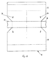
- a Empty space created by the swivel flaps at the front and rear ends is closed, the flaps being dimensioned from the blank are punched that the free end of the swing flaps with the circumference of the cylinder barrel is engaged and forms a lock.
- the positioning of the shipping tube in the rectangular envelope continues improved that the swivel flaps protruding on their side edges Have tabs that engage slots in the side walls of the cuboid when the flaps are pivoted down until the free edge of the flap is on the Shipping tube sits on.
- the slots receiving the noses are expediently in the side walls of the cuboid at a small angle ⁇ to the vertical tilted back, and the flap is used to snap the lugs into the slots by one Angle of 90 ° + ⁇ swiveled.
- Such an arrangement can at the front and be provided at the rear end of the cuboid and the shipping tube, so that the The swivel flap is locked on the shipping tube at two points and thus one secure fixing of the shipping tube is achieved.
- the Flap is preferably curved. This curvature is the circumferential curvature of the shipping tube adjusted so that the free end of the swivel flap Shipping tube encloses on a portion of the circumference and the movement of the Shipping tube locks in the axial direction.
- Such a blocking effect between cuboid wrapper and shipping tube can alternatively also be achieved in that the free end of the swivel flaps, that comes into contact with the shipping tube, designed as an adhesive connection is so that for shipping the swivel flap with the shipping tube through a Adhesive line or a flange attached to the swivel flap with adhesive surface as Securing element is connected.
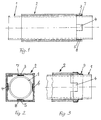
- the cylindrical shipping tube 1 is in the cuboid stabilizing element 2 with a square cross section so that the four inner surfaces of the stabilizing element 2 offset by 90 ° on the top of the shipping tube 1 issue.
- the side surfaces point in the direction strip-shaped tabs 3, 4, 5, 6 extending along the longitudinal axis at least on one, but preferably at both ends.
- the tabs 3, 4, 5 and 6 are on hers Provide underside with an adhesive connector, which is directly on the outer surface of the Shipping tube 1 is set.
- the adhesive connector is preferably an adhesive that adheres to the peripheral surface of the shipping tube 1 is pressed and thus an adhesive connection with him.
- This embodiment is shown in Fig. 1, the adhesive layer, e.g. in the form of an adhesive layer, shown at 7, 8, which is a firm connection between shipping tube 1 and stabilizing element 2.
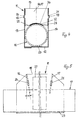
- an adhesive strip 9 is shown, which in Circumferential direction is wound and the tabs 3, 4, 5, 6 and the tabs Adjacent locations of the shipping tube in the circumferential direction and then in enclose axial direction, so that it is also a safe and non-slip Connection between shipping tube and stabilizing element is achieved.
- the shipping tube 10 is a conventional packaging container made of cardboard or the like, which picks up rolled material and protects it from damage during shipping protects.
- the shipping tube 10 is surrounded by a rectangular envelope 11 enclosed, which is a one-piece cardboard blank and from a bottom 12, Side walls 13, 14, top wall 15 and front and rear swivel flap 16, 17 exists.
- the distance between the side walls 16, 17 corresponds to the diameter of the Shipping tube 10 so that the shipping tube 10 from the side walls and the Bottom wall of the wrapper is set.
- front and rear swing flaps 16, 17 formed, the pivot lines of the form the front and rear end of the top wall 15.
- the swivel flaps 16, 17 have lugs or the like.
- the lugs 18, 19 are Punching on the blank, which are formed in the plane of the swivel flaps and when pivoting the swivel flaps down into the slots 20, 21 of the Snap the side panels into place.
- the free outer edge of the swivel flaps 16, 17 is in each case part-circular Rounding or recess 22 provided, the curvature of the curvature the outer surface of the shipping tube 10 is adapted so that the engagement between Swing flap and shipping tube over part of the circumference of the shipping tube takes place and thus a locking intervention between the two is achieved.
- an adhesive layer 23 strip or dot
- This release film is removed when the shipping tube 10 in the Envelope 11 is introduced.
- the shipping tube 10 is after insertion to the Bottom and thus pressed against the central adhesive layer 23.
- This adhesive layer 23 can be in the form of a continuous adhesive strip or in the form of partial strips or Glue points should be formed.
- the free edge 25 of the Swing flap 16, 17, an adhesive layer 26 may be provided to increase the Locking effect between swivel flap and shipping tube an adhesive connection results.
- the adhesive layer 26 itself can form a linear adhesive connection; however, the arrangement can also be such that on the free edge of the Swing flap 16, 17 is punched a tab with an adhesive layer is provided, which instead of locking via lugs and slots the shipping tube 10 improved.
- a sticker is indicated in Fig. 5, which for shipping or transport and contains data and information required by the shipping company.
Landscapes
- Engineering & Computer Science (AREA)
- Mechanical Engineering (AREA)
- Packaging Of Annular Or Rod-Shaped Articles, Wearing Apparel, Cassettes, Or The Like (AREA)
- Character Discrimination (AREA)
- Lining Or Joining Of Plastics Or The Like (AREA)
- Shaping By String And By Release Of Stress In Plastics And The Like (AREA)
- Cable Accessories (AREA)
Abstract
Description
Die Erfindung betrifft ein Stabilisierelement für ein zylindrisches Versandrohr nach
dem Oberbegriff des Anspruches 1.The invention relates to a stabilizing element for a cylindrical shipping tube according to
the preamble of
Zylindrische Versandrohre haben die Eigenschaft, bei ihrer Handhabung abzurollen. Insbesondere für den Postversand stellt ein zylndrisches Versandrohr erhebliche Probleme dar, nicht nur, weil es keine definierte Position einnimmt, und damit eine elektronische Sortier- und Prüfanlage Schwierigkeiten hat, das Versandrohr während des Transportes in eine definierte Position zu bringen, damit das Auslesen der Informationen sicher gewährleistet ist, sondern weil für das sichere Auslesen der Informationen auch eine plane Fläche erforderlich ist, die zum Aufbringen einer Versandinformation geeignet ist.Cylindrical shipping tubes have the property of rolling when they are handled. A cylindrical shipping tube is particularly important for mailing Problems, not only because it has no defined position, and therefore one electronic sorting and inspection system has difficulty holding the shipping tube during to bring the transport into a defined position so that the reading of the Information is guaranteed, but because of the safe reading of the Information also requires a flat surface that is required to apply a Shipping information is suitable.
Diese Schwierigkeiten lassen sich dadurch vermeiden, dass derartige Versandrohre mit einer quadratischen oder rechteckigen Querschnittsform anstelle einer kreisrunden Querschnittsform ausgestaltet werden. Für den Versand von gerolltem Versandgut ist jedoch eine innere Zylinderform unverzichtbar.These difficulties can be avoided by having such shipping tubes with a square or rectangular cross-sectional shape instead of a circular one Cross-sectional shape can be designed. For the shipping of rolled goods however, an inner cylindrical shape is indispensable.
Aufgabe der Erfindung ist, Versandrollen in herkömmlicher zylindrischer Form mit einer für den Versand bestimmten Vorrichtung zu versehen oder auszubilden, bei der die Position der Versandrolle in jeder Lage stabilisiert ist und stets die richtige Zuordnung einer vorbestimmten Position der Versandrolle in bezug auf eine Erkennungsvorrichtung in einer Sortieranlage oder dergl. gewährleistet ist.The object of the invention is to use shipping rolls in a conventional cylindrical shape to provide or train a device intended for shipping, in which the position of the shipping roll is stabilized in every position and always the correct assignment a predetermined position of the shipping roller with respect to a detection device is guaranteed in a sorting system or the like.
Gemäß der Erfindung ist ein derartiges Stabilisierelement nach einem Aspekt der Erfindung so ausgebildet, dass das zylindrische Versandrohr von einem beidseitig offenen symmetrischen Quader-Umhüller allseitig umschlossen ist, und dass der Umhüller zumindest an einem Ende mit dem Versandrohr durch eine Klebeverbindung verbunden ist. Vorzugsweise ist jedoch auch am entgegengesetzten Ende eine entsprechende Klebeverbindung vorgesehen, so dass dann der Umhüller symmetrisch ausgebildet ist. Die Länge des Umhüllers ist dabei kleiner als die Länge des Versand-rohres, das an beiden Enden über den Umhüller vorsteht.According to the invention, such a stabilizing element is according to one aspect of the Invention designed so that the cylindrical shipping tube from one side open symmetrical cuboid wrapper is enclosed on all sides, and that the Envelope at least at one end with the shipping tube through a Adhesive connection is connected. Preferably, however, is also on the opposite A corresponding adhesive connection is provided at the end, so that the wrapper is symmetrical. The length of the wrapper is less than the length of the shipping tube that protrudes from the wrapper at both ends.
Der Umhüller umschließt das Versandrohr allseitig so, dass die vier Seiten des Umhüllers jeweils an vier um 90° versetzten Bereichen mit dem Versandrohr in Anlage stehen. An diesen Stellen weist das jeweilige Ende des Umhüllers einen streifenförmigen Flansch auf, der als Verbindungsmittel mit dem Versandrohr verwendet wird. Wahlweise kann die jeweilige Lasche auf ihrer dem Versandrohr zugewandten Unterseite einen Haftverschluss, z.B. einen Klebeverschluss aufnehmen, so dass die Laschen unmittelbar mit der Umfangsfläche des Versandrohres durch Andrücken verbunden werden. Alternativ können die Laschen ohne Haftverschluss ausgebildet werden, und es wird ein in Umfangsrichtung verlaufendes Klebeband um die Außenseite der Laschen und die unmittelbar angrenzende Umfangsfläche des Versandrohres an den Stellen zwischen den Laschen gewickelt, so dass die Klebeverbindung über den Klebestreifen erfolgt, der die Laschen an dem Versandrohr festlegt.The wrapper encloses the shipping tube on all sides so that the four sides of the Envelope in four areas, each offset by 90 °, with the shipping tube in Plant. At these points the respective end of the wrapper has one strip-shaped flange, which acts as a connection to the shipping tube is used. Optionally, the respective tab on the shipping tube adhesive bottom, e.g. put an adhesive closure, so that the tabs go right through with the peripheral surface of the shipping tube Pressing can be connected. Alternatively, the tabs can be used without an adhesive fastener are formed, and there is a circumferential tape around the outside of the tabs and the immediately adjacent peripheral surface of the Shipping tube wrapped in the places between the tabs so that the Adhesive connection is made via the adhesive strip that holds the tabs on the shipping tube sets.
Anstelle eines die Laschen des Umhüllers mit dem Versandrohr festlegenden Klebebandes kann alternativ auch ein kräftiges Gummiband oder ein Schnurzug verwendet werden, wenn Klebeverbindungen für den speziellen Anwendungszweck unerwünscht sein sollten und wenn das Band so angelegt wird, dass es nicht in axialer Richtung nach außen verrutschen kann.Instead of an adhesive tape fixing the tabs of the wrapper with the shipping tube alternatively a strong rubber band or a cord can be used when adhesive connections for the special application should be undesirable and if the tape is applied so that it is not in axial Can slip outwards.
Eine derartige Ausführungsform eines Stabilisierelementes ist für Versandrohre geeignet, deren Durchmesser ausreichend groß ist, um an einer Seitenfläche des Umhüllers einen Aufkleber plan zu befestigen, der die Informationen und Daten aufnimmt, die von der Erkennungsvorrichtung einer Sortieranlage für den Transport geprüft werden müssen.Such an embodiment of a stabilizing element is for shipping tubes suitable, the diameter of which is sufficiently large to be on a side surface of the Envelope to attach a sticker plan that shows the information and data picks up by the detection device of a sorting system for transport must be checked.
Nach einem weiteren Aspekt der Erfindung ist das zylindrische Rohr von einem beidseitig offenen, quaderförmigen Umhüller bzw. einer Hülle umschlossen und der Umhüller (bzw. die Hülle) weist auf der Innenseite seines Bodens eine Klebeschicht auf, die mit der Unterseite der Versandrolle in Klebeverbindung steht. Damit wird erreicht, dass das zylindrische Versandrohr eine äußere Quaderform erhält, so dass der die Versandinformationen aufnehmende Aufkleber auf einer planen Fläche angeordnet ist und die Erkennungsschaltung der Sortieranlage die Informationen des Aufklebers eindeutig auslesen kann. Des weiteren wird damit erreicht, dass das zylindrische Versandrohr selbst in dem Umhüller festgelegt wird und Umhüller und Versandrohr sich beim Transport nicht voneinander lösen. Hierzu wird der Klebestreifen auf der Bodenfläche des Umhüller-Zuschnittes aufgebracht, durch eine Abziehfolie bedeckt, beim Einsetzen des zylindrischen Versandrohres in den Umhüller die Abdeckschicht abgezogen und das Versandrohr auf dem Streifen Klebstoff, der sich über die gesamte Länge des Umhüller-Bodens erstrecken kann, angedrückt und festgelegt.According to another aspect of the invention, the cylindrical tube is one enclosed on both sides, cuboidal envelopes or an envelope and the Wrapper (or the shell) has an adhesive layer on the inside of its bottom that is glued to the underside of the shipping roll. So that will achieved that the cylindrical shipping tube receives an outer cuboid shape, so that the the shipping information stickers are arranged on a flat surface is and the recognition circuit of the sorting system is the information of the sticker can read out clearly. It is also achieved that the cylindrical Shipping tube itself is set in the wrapper and wrapper and shipping tube do not separate from each other during transport. For this purpose, the adhesive strip on the Bottom surface of the wrapper blank applied, covered by a release film, when inserting the cylindrical shipping tube into the wrapper, the cover layer peeled off and the shipping tube on the strip of adhesive that extends over the entire Length of the wrapper base can extend, pressed and fixed.
Die Dimensionen des Umhüllers sind so ausgelegt, dass die Schmalseite des quaderförmigen Umhüllers dem Durchmesser der Versandrolle entsprechend ausgelegt ist, und dass die Dimension der Breitseite des Quaders der Abmessung des Aufklebers entspricht, der die für den Versand erforderlichen Adressen-, Leit- und Gebühreninformationen und dergl. aufnimmt.The dimensions of the envelope are designed so that the narrow side of the cuboid Is designed according to the diameter of the shipping roll, and that the dimension of the broad side of the cuboid of the dimension of the sticker corresponds to the address, routing and fee information required for shipping and the like.
Die Breitseite des quaderförmigen Umhüllers muss dabei nach den Vorschriften der Post in den Abmessungen so ausgelegt sein, dass der Aufkleber auf einer planen Fläche aufgeklebt bzw. befestigt ist, so dass der Umhüller zur Aufnahme eines zylindrischen Versandrohres mit relativ kleinem Durchmesser nicht mit quadratischem, sondern mit rechteckförmigem Querschnitt ausgebildet wird, wobei die größere Dimension des Rechteckquerschnittes der Aufkleber-Abmessung entsprechend ausgelegt wird.The broad side of the cuboidal envelope must according to the regulations of Post in dimensions so that the sticker is on a plan Surface is glued or fastened so that the wrapper for receiving a cylindrical shipping tube with a relatively small diameter not with square, but is formed with a rectangular cross section, wherein the larger dimension of the rectangular cross section of the sticker dimension is interpreted accordingly.
In weiterer Ausgestaltung der Erfindung ist die schmale Deckseite des quaderförmigen Umhüllers an beiden Endabschnitten als Schwenkklappe ausgebildet, die nach unten geklappt sich gegen die Oberkante des Versandrohres anlegt und das Versandrohr arretiert. Zwischen der Oberkante des im Quader mittels Klebestreifen festgelegten Versandrohres und der Deckseite des quaderförmigen Umhüllers besteht somit ein Leerraum, der durch die am vorderen und am hinteren Ende ausgebildeten Schwenkklappen verschlossen wird, wobei die Klappen aus dem Zuschnitt so dimensioniert gestanzt sind, dass das freie Ende der Schwenkklappen mit dem Umfang des Zylinderrohres in Eingriff steht und eine Arretierung bildet.In a further embodiment of the invention, the narrow top side of the cuboid Envelope formed at both end portions as a swing flap that is facing down folded against the top edge of the shipping tube and the shipping tube locked. Between the upper edge of the fixed in the cuboid with adhesive tape Shipping tube and the top of the cuboidal envelope is therefore a Empty space created by the swivel flaps at the front and rear ends is closed, the flaps being dimensioned from the blank are punched that the free end of the swing flaps with the circumference of the cylinder barrel is engaged and forms a lock.
Die Positionierung des Versandrohres im quaderförmigen Umhüller wird weiter dadurch verbessert, dass die Schwenkklappen an ihren Seitenrändern vorstehende Nasen aufweisen, die in Schlitze in den Seitenwänden des Quaders eingreifen, wenn die Klappen nach unten geschwenkt werden, bis die freie Kante der Klappe auf dem Versandrohr aufsitzt. Zweckmäßigerweise sind die die Nasen aufnehmenden Schlitze in den Seitenwänden des Quaders in einem kleinen Winkel α zur Vertikalen nach hinten geneigt, und die Klappe wird zum Einrasten der Nasen in die Schlitze um einen Winkel von 90° + α geschwenkt. Eine derartige Anordnung kann am vorderen und am hinteren Ende des Quaders und des Versandrohres vorgesehen sein, so dass die Schwenkklappe an zwei Stellen sperrend auf dem Versandrohr aufsitzt und damit eine sichere Festlegung des Versandrohres erreicht wird. An ihrem freien Rand ist die Klappe vorzugsweise gekrümmt ausgebildet. Diese Krümmung ist der Umfangskrümmung des Versandrohres angepasst, so dass das freie Ende der Schwenkklappe das Versandrohr auf einem Teilabschnitt des Umfanges umschließt und die Bewegung des Versandrohres in axialer Richtung sperrt.The positioning of the shipping tube in the rectangular envelope continues improved that the swivel flaps protruding on their side edges Have tabs that engage slots in the side walls of the cuboid when the flaps are pivoted down until the free edge of the flap is on the Shipping tube sits on. The slots receiving the noses are expediently in the side walls of the cuboid at a small angle α to the vertical tilted back, and the flap is used to snap the lugs into the slots by one Angle of 90 ° + α swiveled. Such an arrangement can at the front and be provided at the rear end of the cuboid and the shipping tube, so that the The swivel flap is locked on the shipping tube at two points and thus one secure fixing of the shipping tube is achieved. At its free edge is the Flap is preferably curved. This curvature is the circumferential curvature of the shipping tube adjusted so that the free end of the swivel flap Shipping tube encloses on a portion of the circumference and the movement of the Shipping tube locks in the axial direction.
Eine derartige Sperrwirkung zwischen quaderförmigem Umhüller und Versandrohr kann alternativ auch dadurch erreicht werden, dass das freie Ende der Schwenkklappen, das mit dem Versandrohr in Anlage kommt, als Klebeverbindung ausgebildet wird, so dass für den Versand die Schwenkklappe mit dem Versandrohr durch eine Klebelinie bzw. eine an der Schwenkklappe befestigten Flansch mit Klebefläche als Sicherungselement verbunden ist.Such a blocking effect between cuboid wrapper and shipping tube can alternatively also be achieved in that the free end of the swivel flaps, that comes into contact with the shipping tube, designed as an adhesive connection is so that for shipping the swivel flap with the shipping tube through a Adhesive line or a flange attached to the swivel flap with adhesive surface as Securing element is connected.
Nachstehend wird die Erfindung in Verbindung mit der Zeichnung anhand von Ausführungsbeispielen erläutert. Es zeigt:
- Fig. 1
- ein quaderförmiges Stabilisierelement mit zylindrischem Versandrohr, in Seitenansicht,
- Fig. 2
- eine Frontansicht der Darstellung nach Fig. 1,
- Fig. 3
- eine Variante der Verbindung zwischen Stabilisierelement und Versandrohr,
- Fig. 4
- eine weitere Ausführungsform des erfindungsgemäßen Versandrohres mit Stabilisierelement, in Seitenansicht,
- Fig. 5
- eine Vorderansicht der Darstellung nach Fig. 4, teilweise im Schnitt, und
- Fig. 6
- einen Zuschnitt des quaderförmigen Umhüllers mit geänderten Abmessungen.
- Fig. 1
- a cuboid stabilizing element with a cylindrical shipping tube, in side view,
- Fig. 2
- 2 shows a front view of the representation according to FIG. 1,
- Fig. 3
- a variant of the connection between the stabilizing element and shipping tube,
- Fig. 4
- another embodiment of the shipping tube according to the invention with stabilizing element, in side view,
- Fig. 5
- 4, partly in section, and
- Fig. 6
- a cut of the rectangular envelope with changed dimensions.
Das zylindrische Versandrohr 1 wird in dem quaderförmigen Stabilisierungselement 2
mit quadratischem Querschnitt so aufgenommen, dass die vier Innenflächen des Stabilisierungselementes
2 jeweils um 90° versetzt an der Oberseite des Versandrohres 1
anliegen. In Verlängerung dieser Anlagebereiche weisen die Seitenflächen in Richtung
der Längsachse verlaufende streifenförmige Laschen 3, 4, 5, 6 zumindest an einem,
vorzugsweise aber an beiden Enden auf. Die Laschen 3, 4, 5 und 6 sind auf ihrer
Unterseite mit einem Haftverbinder versehen, der unmittelbar auf der Außenfläche des
Versandrohres 1 festgelegt wird. Der Haftverbinder ist vorzugsweise ein Kleber, der an
der Umfangsfläche des Versandrohres 1 angedrückt wird und damit eine Haftverbindung
mit ihm eingeht. Diese Ausführungsform ist in Fig. 1 dargestellt, wobei die Haftschicht,
z.B. in Form einer Klebeschicht, mit 7, 8 gezeigt ist, die eine feste Verbindung
zwischen Versandrohr 1 und Stabilisierungselement 2 herstellt.The
Bei der Ausführungsform nach Fig. 3 ist ein Klebestreifen 9 dargestellt, der in
Umfangs-richtung gewickelt ist und der die Laschen 3, 4, 5, 6 und die den Laschen
benachbar-ten Stellen des Versandrohres in Umfangsrichtung und anschließend in
axialer Rich-tung umschließen, so dass damit ebenfalls eine sichere und rutschfreie
Verbindung zwischen Versandrohr und Stabilisierelement erzielt wird.3, an adhesive strip 9 is shown, which in
Circumferential direction is wound and the
Das Versandrohr 10 ist ein herkömmlicher Verpackungsbehälter aus Pappe, Karton
oder dergl., der gerolltes Material aufnimmt und es gegen Beschädigung beim Versand
schützt. Das Versandrohr 10 wird von einem quaderförmigen Umhüller 11
umschlossen, der ein einstückiger Kartonzuschnitt ist und aus einem Boden 12,
Seitenwänden 13, 14, Deckwand 15 sowie vorderer und hinterer Schwenkklappe 16,
17 besteht. Der Abstand der Seitenwände 16, 17 entspricht dem Durchmesser des
Versandrohres 10, so dass das Versandrohr 10 von den Seitenwänden und der
Bodenwand des Umhüllers festgelegt ist. An den beiden Enden des Umhüllers 11 sind
vordere und hintere Schwenkklappen 16, 17 ausgebildet, deren Schwenklinien den
vorderen und hinteren Abschluss der Deckwand 15 bilden. Die Schwenkklappen 16,
17 weisen Nasen oder dergl. Verriegelungselemente 18, 19 auf, die mit schlitzartigen
Öffnungen 20, 21 in den Seitenwänden 13, 14 des Umhüllers 11 beim Verschwenken
der Schwenkklappen nach unten in Eingriff kommen. Die Nasen 18, 19 sind
Ausstanzungen am Zuschnitt, die in der Ebene der Schwenkklappen ausgebildet sind
und beim Verschwenken der Schwenkklappen nach abwärts in die Schlitze 20, 21 der
Seitenwände einrasten.The
Die freie Außenkante der Schwenkklappen 16, 17 ist jeweils mit einer teilkreisförmigen
Rundung bzw. Aussparung 22 versehen, deren Krümmung der Krümmung
der Außenfläche des Versandrohres 10 angepasst ist, so dass der Eingriff zwischen
Schwenkklappe und Versandrohr über einen Teil des Umfangs des Versandrohres
stattfindet und damit ein Sperreingriff zwischen beiden erreicht wird.The free outer edge of the swivel flaps 16, 17 is in each case part-circular
Rounding or
Auf der Innenseite des Bodens 12 des Umhüllers 11 ist eine durch eine Klebeschicht
23 (streifenförmig oder punktförmig) aufgebracht, die durch eine Abziehfolie
24schützt ist. Diese Abziehfolie wird entfernt, wenn das Versandrohr 10 in den
Umhüller 11eingeführt wird. Das Versandrohr 10 wird nach dem Einsetzen an den
Boden und damit an die mittige Klebeschicht 23 angedrückt. Diese Klebeschicht 23
kann in Form eines durchgehenden Klebestreifens oder in Form von Teilstreifen oder
Klebepunkten ausgebildet sein. Des weiteren kann an der freien Kante 25 der
Schwenkklappe 16, 17 eine Klebeschicht 26 vorgesehen sein, die zur Erhöhung der
Sperrwirkung zwischen Schwenkklappe und Versandrohr eine Klebeverbindung
ergibt. Die Klebeschicht 26 selbst kann eine linienförmige Klebeverbindung ausbilden;
die Anordnung kann jedoch auch so getroffen sein, dass an der freien Kante der
Schwenkklappe 16, 17 eine Lasche angestanzt ist, die mit einer Klebeschicht
versehen ist, welche anstelle der Verriegelung über Nasen und Schlitze die Festlegung
des Versandrohres 10 verbessert. On the inside of the bottom 12 of the
Mit 27 ist in Fig. 5 ein Aufkleber angedeutet, der die für den Versand bzw. Transport und für das Versandunternehmen erforderliche Daten und Informationen enthält.5, a sticker is indicated in Fig. 5, which for shipping or transport and contains data and information required by the shipping company.
Claims (12)
Applications Claiming Priority (4)
| Application Number | Priority Date | Filing Date | Title |
|---|---|---|---|
| DE20109914U | 2001-06-18 | ||
| DE20109913U DE20109913U1 (en) | 2001-06-18 | 2001-06-18 | Stabilizing element for cylindrical shipping tube |
| DE20109913U | 2001-06-18 | ||
| DE20109914U DE20109914U1 (en) | 2001-06-18 | 2001-06-18 | Cylindrical shipping tube with stabilizing element |
Publications (2)
| Publication Number | Publication Date |
|---|---|
| EP1270436A1 true EP1270436A1 (en) | 2003-01-02 |
| EP1270436B1 EP1270436B1 (en) | 2008-10-01 |
Family
ID=26057041
Family Applications (1)
| Application Number | Title | Priority Date | Filing Date |
|---|---|---|---|
| EP02012283A Expired - Lifetime EP1270436B1 (en) | 2001-06-18 | 2002-06-05 | Cylindrical mail tube with stabilising element |
Country Status (3)
| Country | Link |
|---|---|
| EP (1) | EP1270436B1 (en) |
| AT (1) | ATE409657T1 (en) |
| DE (1) | DE50212824D1 (en) |
Cited By (1)
| Publication number | Priority date | Publication date | Assignee | Title |
|---|---|---|---|---|
| CN112638791A (en) * | 2018-09-21 | 2021-04-09 | 住友化学株式会社 | Method for manufacturing package of cylindrical sputtering target and package |
Citations (5)
| Publication number | Priority date | Publication date | Assignee | Title |
|---|---|---|---|---|
| GB832302A (en) * | 1957-02-25 | 1960-04-06 | Robert Samuel Shelly | Multi-tube structures for example for containers and method of making same |
| WO1982003062A1 (en) * | 1981-03-03 | 1982-09-16 | Sandberg Jonny Bengt | A holder for keeping rolled sheets |
| DE29504869U1 (en) * | 1995-03-22 | 1995-06-01 | Müller, Erich, 93086 Wörth | Anti-rotation device for round tubes, rolls or the like. for mailing |
| DE20105528U1 (en) * | 2001-03-28 | 2001-06-13 | Müller, Dietrich, 94356 Kirchroth | Cylindrical shipping tube with wrapper |
| DE20107727U1 (en) * | 2001-05-09 | 2001-08-09 | Müller, Dietrich, 94356 Kirchroth | Cylindrical shipping tube with stabilizing element |
-
2002
- 2002-06-05 AT AT02012283T patent/ATE409657T1/en active
- 2002-06-05 DE DE50212824T patent/DE50212824D1/en not_active Expired - Lifetime
- 2002-06-05 EP EP02012283A patent/EP1270436B1/en not_active Expired - Lifetime
Patent Citations (5)
| Publication number | Priority date | Publication date | Assignee | Title |
|---|---|---|---|---|
| GB832302A (en) * | 1957-02-25 | 1960-04-06 | Robert Samuel Shelly | Multi-tube structures for example for containers and method of making same |
| WO1982003062A1 (en) * | 1981-03-03 | 1982-09-16 | Sandberg Jonny Bengt | A holder for keeping rolled sheets |
| DE29504869U1 (en) * | 1995-03-22 | 1995-06-01 | Müller, Erich, 93086 Wörth | Anti-rotation device for round tubes, rolls or the like. for mailing |
| DE20105528U1 (en) * | 2001-03-28 | 2001-06-13 | Müller, Dietrich, 94356 Kirchroth | Cylindrical shipping tube with wrapper |
| DE20107727U1 (en) * | 2001-05-09 | 2001-08-09 | Müller, Dietrich, 94356 Kirchroth | Cylindrical shipping tube with stabilizing element |
Cited By (1)
| Publication number | Priority date | Publication date | Assignee | Title |
|---|---|---|---|---|
| CN112638791A (en) * | 2018-09-21 | 2021-04-09 | 住友化学株式会社 | Method for manufacturing package of cylindrical sputtering target and package |
Also Published As
| Publication number | Publication date |
|---|---|
| EP1270436B1 (en) | 2008-10-01 |
| DE50212824D1 (en) | 2008-11-13 |
| ATE409657T1 (en) | 2008-10-15 |
Similar Documents
| Publication | Publication Date | Title |
|---|---|---|
| DE102020214724A1 (en) | Holding device for containers, in particular cans, blanks therefor and containers herewith | |
| DE2839913C2 (en) | Box for packaging elongated objects, in particular ampoules | |
| DE3127334A1 (en) | "BOX FOR A TAPE CASSETTE" | |
| DE2821623C2 (en) | Folding dispenser box for a spiral with electronic components | |
| DE8328150U1 (en) | Trailer for a container | |
| DE2251685C3 (en) | Box-shaped carrier for bottles folded from a blank | |
| DE69812279T2 (en) | Packaging box with a holder | |
| DE602004002233T2 (en) | Presentation box with elements for preventing rotation and displacement of a container inserted in the box | |
| DE69727267T2 (en) | Carrier for packaging tubular elements with varying lengths | |
| DE9005868U1 (en) | Metal packaging with sealable profile edge | |
| EP1270436A1 (en) | Stabilising element for a cylindrical mail tube | |
| DE4316749A1 (en) | A label that, together with the surface of a bottle or a container, forms a space for inserting a leaflet (package insert) and protects it against breakage and exposure to light | |
| DE60132030T2 (en) | Packaging for tubular objects with accessories and inspection windows | |
| DE29504700U1 (en) | Container made of one-piece cardboard or cardboard blank with a convex-walled, constant cross-section | |
| DE20109914U1 (en) | Cylindrical shipping tube with stabilizing element | |
| DE20109913U1 (en) | Stabilizing element for cylindrical shipping tube | |
| DE19819176C2 (en) | Device for packaging fluorescent ring lamps | |
| DE29803148U1 (en) | Flat blank for the production of a carrier for the transport of bottles or bottle-like containers | |
| DE102018123312B4 (en) | Combination packaging especially for bottles | |
| DE9101626U1 (en) | Packaging for video cassettes | |
| DE9408308U1 (en) | Shipping packaging | |
| DE9405322U1 (en) | Packing box | |
| DE29504869U1 (en) | Anti-rotation device for round tubes, rolls or the like. for mailing | |
| DE20107727U1 (en) | Cylindrical shipping tube with stabilizing element | |
| DE1486205C3 (en) | Packaging base made of cardboard or similar material |
Legal Events
| Date | Code | Title | Description |
|---|---|---|---|
| PUAI | Public reference made under article 153(3) epc to a published international application that has entered the european phase |
Free format text: ORIGINAL CODE: 0009012 |
|
| AK | Designated contracting states |
Kind code of ref document: A1 Designated state(s): AT BE CH CY DE DK ES FI FR GB GR IE IT LI LU MC NL PT SE TR |
|
| AX | Request for extension of the european patent |
Free format text: AL;LT;LV;MK;RO;SI |
|
| 17P | Request for examination filed |
Effective date: 20030603 |
|
| AKX | Designation fees paid |
Designated state(s): AT BE CH CY DE DK ES FI FR GB GR IE IT LI LU MC NL PT SE TR |
|
| 17Q | First examination report despatched |
Effective date: 20040701 |
|
| RTI1 | Title (correction) |
Free format text: CYLINDRICAL MAIL TUBE WITH STABILISING ELEMENT |
|
| GRAP | Despatch of communication of intention to grant a patent |
Free format text: ORIGINAL CODE: EPIDOSNIGR1 |
|
| GRAS | Grant fee paid |
Free format text: ORIGINAL CODE: EPIDOSNIGR3 |
|
| GRAA | (expected) grant |
Free format text: ORIGINAL CODE: 0009210 |
|
| AK | Designated contracting states |
Kind code of ref document: B1 Designated state(s): AT BE CH CY DE DK ES FI FR GB GR IE IT LI LU MC NL PT SE TR |
|
| REG | Reference to a national code |
Ref country code: GB Ref legal event code: FG4D Free format text: NOT ENGLISH |
|
| REG | Reference to a national code |
Ref country code: CH Ref legal event code: EP |
|
| REG | Reference to a national code |
Ref country code: IE Ref legal event code: FG4D Free format text: LANGUAGE OF EP DOCUMENT: GERMAN |
|
| REF | Corresponds to: |
Ref document number: 50212824 Country of ref document: DE Date of ref document: 20081113 Kind code of ref document: P |
|
| REG | Reference to a national code |
Ref country code: CH Ref legal event code: NV Representative=s name: LUCHS & PARTNER PATENTANWAELTE |
|
| NLV1 | Nl: lapsed or annulled due to failure to fulfill the requirements of art. 29p and 29m of the patents act | ||
| REG | Reference to a national code |
Ref country code: IE Ref legal event code: FD4D |
|
| PG25 | Lapsed in a contracting state [announced via postgrant information from national office to epo] |
Ref country code: ES Free format text: LAPSE BECAUSE OF FAILURE TO SUBMIT A TRANSLATION OF THE DESCRIPTION OR TO PAY THE FEE WITHIN THE PRESCRIBED TIME-LIMIT Effective date: 20090112 |
|
| PG25 | Lapsed in a contracting state [announced via postgrant information from national office to epo] |
Ref country code: NL Free format text: LAPSE BECAUSE OF FAILURE TO SUBMIT A TRANSLATION OF THE DESCRIPTION OR TO PAY THE FEE WITHIN THE PRESCRIBED TIME-LIMIT Effective date: 20081001 Ref country code: PT Free format text: LAPSE BECAUSE OF FAILURE TO SUBMIT A TRANSLATION OF THE DESCRIPTION OR TO PAY THE FEE WITHIN THE PRESCRIBED TIME-LIMIT Effective date: 20090302 Ref country code: FI Free format text: LAPSE BECAUSE OF FAILURE TO SUBMIT A TRANSLATION OF THE DESCRIPTION OR TO PAY THE FEE WITHIN THE PRESCRIBED TIME-LIMIT Effective date: 20081001 |
|
| PG25 | Lapsed in a contracting state [announced via postgrant information from national office to epo] |
Ref country code: DK Free format text: LAPSE BECAUSE OF FAILURE TO SUBMIT A TRANSLATION OF THE DESCRIPTION OR TO PAY THE FEE WITHIN THE PRESCRIBED TIME-LIMIT Effective date: 20081001 Ref country code: IE Free format text: LAPSE BECAUSE OF FAILURE TO SUBMIT A TRANSLATION OF THE DESCRIPTION OR TO PAY THE FEE WITHIN THE PRESCRIBED TIME-LIMIT Effective date: 20081001 |
|
| PLBE | No opposition filed within time limit |
Free format text: ORIGINAL CODE: 0009261 |
|
| STAA | Information on the status of an ep patent application or granted ep patent |
Free format text: STATUS: NO OPPOSITION FILED WITHIN TIME LIMIT |
|
| PG25 | Lapsed in a contracting state [announced via postgrant information from national office to epo] |
Ref country code: IT Free format text: LAPSE BECAUSE OF FAILURE TO SUBMIT A TRANSLATION OF THE DESCRIPTION OR TO PAY THE FEE WITHIN THE PRESCRIBED TIME-LIMIT Effective date: 20081001 Ref country code: SE Free format text: LAPSE BECAUSE OF FAILURE TO SUBMIT A TRANSLATION OF THE DESCRIPTION OR TO PAY THE FEE WITHIN THE PRESCRIBED TIME-LIMIT Effective date: 20090101 |
|
| 26N | No opposition filed |
Effective date: 20090702 |
|
| BERE | Be: lapsed |
Owner name: MULLER, DIETRICH Effective date: 20090630 |
|
| PG25 | Lapsed in a contracting state [announced via postgrant information from national office to epo] |
Ref country code: MC Free format text: LAPSE BECAUSE OF NON-PAYMENT OF DUE FEES Effective date: 20090630 |
|
| GBPC | Gb: european patent ceased through non-payment of renewal fee |
Effective date: 20090605 |
|
| PG25 | Lapsed in a contracting state [announced via postgrant information from national office to epo] |
Ref country code: GB Free format text: LAPSE BECAUSE OF NON-PAYMENT OF DUE FEES Effective date: 20090605 |
|
| PG25 | Lapsed in a contracting state [announced via postgrant information from national office to epo] |
Ref country code: BE Free format text: LAPSE BECAUSE OF NON-PAYMENT OF DUE FEES Effective date: 20090630 |
|
| PG25 | Lapsed in a contracting state [announced via postgrant information from national office to epo] |
Ref country code: GR Free format text: LAPSE BECAUSE OF FAILURE TO SUBMIT A TRANSLATION OF THE DESCRIPTION OR TO PAY THE FEE WITHIN THE PRESCRIBED TIME-LIMIT Effective date: 20090102 |
|
| PGFP | Annual fee paid to national office [announced via postgrant information from national office to epo] |
Ref country code: CH Payment date: 20100614 Year of fee payment: 9 |
|
| PG25 | Lapsed in a contracting state [announced via postgrant information from national office to epo] |
Ref country code: LU Free format text: LAPSE BECAUSE OF NON-PAYMENT OF DUE FEES Effective date: 20090605 |
|
| PG25 | Lapsed in a contracting state [announced via postgrant information from national office to epo] |
Ref country code: TR Free format text: LAPSE BECAUSE OF FAILURE TO SUBMIT A TRANSLATION OF THE DESCRIPTION OR TO PAY THE FEE WITHIN THE PRESCRIBED TIME-LIMIT Effective date: 20081001 |
|
| PGFP | Annual fee paid to national office [announced via postgrant information from national office to epo] |
Ref country code: AT Payment date: 20110613 Year of fee payment: 10 |
|
| PG25 | Lapsed in a contracting state [announced via postgrant information from national office to epo] |
Ref country code: CY Free format text: LAPSE BECAUSE OF FAILURE TO SUBMIT A TRANSLATION OF THE DESCRIPTION OR TO PAY THE FEE WITHIN THE PRESCRIBED TIME-LIMIT Effective date: 20081001 |
|
| REG | Reference to a national code |
Ref country code: CH Ref legal event code: PL |
|
| PG25 | Lapsed in a contracting state [announced via postgrant information from national office to epo] |
Ref country code: CH Free format text: LAPSE BECAUSE OF NON-PAYMENT OF DUE FEES Effective date: 20110630 Ref country code: LI Free format text: LAPSE BECAUSE OF NON-PAYMENT OF DUE FEES Effective date: 20110630 |
|
| PGFP | Annual fee paid to national office [announced via postgrant information from national office to epo] |
Ref country code: DE Payment date: 20120629 Year of fee payment: 11 |
|
| PGFP | Annual fee paid to national office [announced via postgrant information from national office to epo] |
Ref country code: FR Payment date: 20120705 Year of fee payment: 11 |
|
| REG | Reference to a national code |
Ref country code: AT Ref legal event code: MM01 Ref document number: 409657 Country of ref document: AT Kind code of ref document: T Effective date: 20120605 |
|
| PG25 | Lapsed in a contracting state [announced via postgrant information from national office to epo] |
Ref country code: AT Free format text: LAPSE BECAUSE OF NON-PAYMENT OF DUE FEES Effective date: 20120605 |
|
| REG | Reference to a national code |
Ref country code: DE Ref legal event code: R082 Ref document number: 50212824 Country of ref document: DE |
|
| REG | Reference to a national code |
Ref country code: DE Ref legal event code: R119 Ref document number: 50212824 Country of ref document: DE Effective date: 20140101 |
|
| REG | Reference to a national code |
Ref country code: FR Ref legal event code: ST Effective date: 20140228 |
|
| PG25 | Lapsed in a contracting state [announced via postgrant information from national office to epo] |
Ref country code: DE Free format text: LAPSE BECAUSE OF NON-PAYMENT OF DUE FEES Effective date: 20140101 |
|
| PG25 | Lapsed in a contracting state [announced via postgrant information from national office to epo] |
Ref country code: FR Free format text: LAPSE BECAUSE OF NON-PAYMENT OF DUE FEES Effective date: 20130701 |