EP1218104B1 - Method and installation for eliminating metal cations from a liquid with polyazacycloalkane resins grafted on a support - Google Patents
Method and installation for eliminating metal cations from a liquid with polyazacycloalkane resins grafted on a support Download PDFInfo
- Publication number
- EP1218104B1 EP1218104B1 EP00958739A EP00958739A EP1218104B1 EP 1218104 B1 EP1218104 B1 EP 1218104B1 EP 00958739 A EP00958739 A EP 00958739A EP 00958739 A EP00958739 A EP 00958739A EP 1218104 B1 EP1218104 B1 EP 1218104B1
- Authority
- EP
- European Patent Office
- Prior art keywords
- resin
- liquid
- silica
- polyazacycloalkane
- column
- Prior art date
- Legal status (The legal status is an assumption and is not a legal conclusion. Google has not performed a legal analysis and makes no representation as to the accuracy of the status listed.)
- Expired - Lifetime
Links
- 229920005989 resin Polymers 0.000 title claims abstract description 144
- 239000011347 resin Substances 0.000 title claims abstract description 144
- 238000000034 method Methods 0.000 title claims abstract description 132
- 239000007788 liquid Substances 0.000 title claims abstract description 42
- 229910052751 metal Inorganic materials 0.000 title claims abstract description 41
- 239000002184 metal Substances 0.000 title claims abstract description 39
- 238000009434 installation Methods 0.000 title claims abstract description 33
- 150000001768 cations Chemical class 0.000 title claims abstract description 29
- 239000007787 solid Substances 0.000 claims abstract description 20
- 239000003456 ion exchange resin Substances 0.000 claims abstract description 9
- 229920003303 ion-exchange polymer Polymers 0.000 claims abstract description 9
- NWUYHJFMYQTDRP-UHFFFAOYSA-N 1,2-bis(ethenyl)benzene;1-ethenyl-2-ethylbenzene;styrene Chemical compound C=CC1=CC=CC=C1.CCC1=CC=CC=C1C=C.C=CC1=CC=CC=C1C=C NWUYHJFMYQTDRP-UHFFFAOYSA-N 0.000 claims abstract description 7
- 230000001143 conditioned effect Effects 0.000 claims abstract description 6
- VYPSYNLAJGMNEJ-UHFFFAOYSA-N Silicium dioxide Chemical compound O=[Si]=O VYPSYNLAJGMNEJ-UHFFFAOYSA-N 0.000 claims description 129
- 239000000243 solution Substances 0.000 claims description 55
- 239000000377 silicon dioxide Substances 0.000 claims description 46
- 230000000694 effects Effects 0.000 claims description 38
- 229910052770 Uranium Inorganic materials 0.000 claims description 36
- 230000008929 regeneration Effects 0.000 claims description 34
- 238000011069 regeneration method Methods 0.000 claims description 34
- 239000000741 silica gel Substances 0.000 claims description 26
- 229910002027 silica gel Inorganic materials 0.000 claims description 26
- 230000003750 conditioning effect Effects 0.000 claims description 23
- 150000002739 metals Chemical class 0.000 claims description 19
- 229920001429 chelating resin Polymers 0.000 claims description 18
- 229910052768 actinide Inorganic materials 0.000 claims description 15
- 150000001255 actinides Chemical class 0.000 claims description 15
- 125000006850 spacer group Chemical group 0.000 claims description 15
- 239000000499 gel Substances 0.000 claims description 14
- 150000002500 ions Chemical class 0.000 claims description 14
- 239000003463 adsorbent Substances 0.000 claims description 12
- XLYOFNOQVPJJNP-UHFFFAOYSA-N water Chemical compound O XLYOFNOQVPJJNP-UHFFFAOYSA-N 0.000 claims description 12
- GRYLNZFGIOXLOG-UHFFFAOYSA-N Nitric acid Chemical compound O[N+]([O-])=O GRYLNZFGIOXLOG-UHFFFAOYSA-N 0.000 claims description 11
- 239000007853 buffer solution Substances 0.000 claims description 10
- 229910017604 nitric acid Inorganic materials 0.000 claims description 9
- 238000011144 upstream manufacturing Methods 0.000 claims description 9
- 229910001385 heavy metal Inorganic materials 0.000 claims description 8
- 229910052723 transition metal Inorganic materials 0.000 claims description 8
- 239000010949 copper Substances 0.000 claims description 7
- 239000012153 distilled water Substances 0.000 claims description 7
- 229910052747 lanthanoid Inorganic materials 0.000 claims description 7
- 150000002602 lanthanoids Chemical class 0.000 claims description 7
- 150000003624 transition metals Chemical class 0.000 claims description 7
- 239000004793 Polystyrene Substances 0.000 claims description 6
- 125000000217 alkyl group Chemical group 0.000 claims description 6
- 229910052782 aluminium Inorganic materials 0.000 claims description 6
- 229910052802 copper Inorganic materials 0.000 claims description 6
- 238000010438 heat treatment Methods 0.000 claims description 6
- 229920002223 polystyrene Polymers 0.000 claims description 6
- 229910052725 zinc Inorganic materials 0.000 claims description 6
- MDAXKAUIABOHTD-UHFFFAOYSA-N 1,4,8,11-tetraazacyclotetradecane Chemical compound C1CNCCNCCCNCCNC1 MDAXKAUIABOHTD-UHFFFAOYSA-N 0.000 claims description 5
- 229910052778 Plutonium Inorganic materials 0.000 claims description 5
- 229920000620 organic polymer Polymers 0.000 claims description 5
- 229920006395 saturated elastomer Polymers 0.000 claims description 5
- RYGMFSIKBFXOCR-UHFFFAOYSA-N Copper Chemical compound [Cu] RYGMFSIKBFXOCR-UHFFFAOYSA-N 0.000 claims description 4
- 229910052784 alkaline earth metal Inorganic materials 0.000 claims description 4
- 150000001342 alkaline earth metals Chemical class 0.000 claims description 4
- 229910052788 barium Inorganic materials 0.000 claims description 4
- 229910052737 gold Inorganic materials 0.000 claims description 4
- 125000000896 monocarboxylic acid group Chemical group 0.000 claims description 4
- 229920000058 polyacrylate Polymers 0.000 claims description 4
- 230000002285 radioactive effect Effects 0.000 claims description 4
- 230000001172 regenerating effect Effects 0.000 claims description 4
- 229910052695 Americium Inorganic materials 0.000 claims description 3
- 229910052693 Europium Inorganic materials 0.000 claims description 3
- 229910052688 Gadolinium Inorganic materials 0.000 claims description 3
- UFHFLCQGNIYNRP-UHFFFAOYSA-N Hydrogen Chemical compound [H][H] UFHFLCQGNIYNRP-UHFFFAOYSA-N 0.000 claims description 3
- 229910052785 arsenic Inorganic materials 0.000 claims description 3
- 229910052790 beryllium Inorganic materials 0.000 claims description 3
- 239000008280 blood Substances 0.000 claims description 3
- 210000004369 blood Anatomy 0.000 claims description 3
- 229910052793 cadmium Inorganic materials 0.000 claims description 3
- 229910052791 calcium Inorganic materials 0.000 claims description 3
- 229910052804 chromium Inorganic materials 0.000 claims description 3
- 229910052739 hydrogen Inorganic materials 0.000 claims description 3
- 239000001257 hydrogen Substances 0.000 claims description 3
- 125000004435 hydrogen atom Chemical group [H]* 0.000 claims description 3
- 229910052742 iron Inorganic materials 0.000 claims description 3
- 229910052745 lead Inorganic materials 0.000 claims description 3
- 229910052749 magnesium Inorganic materials 0.000 claims description 3
- 229910052748 manganese Inorganic materials 0.000 claims description 3
- 229910052759 nickel Inorganic materials 0.000 claims description 3
- 229910052709 silver Inorganic materials 0.000 claims description 3
- 239000002904 solvent Substances 0.000 claims description 3
- 229910052712 strontium Inorganic materials 0.000 claims description 3
- 238000006467 substitution reaction Methods 0.000 claims description 3
- 229910052684 Cerium Inorganic materials 0.000 claims description 2
- 239000002253 acid Substances 0.000 claims description 2
- 150000001348 alkyl chlorides Chemical class 0.000 claims description 2
- 150000001350 alkyl halides Chemical class 0.000 claims description 2
- XAGFODPZIPBFFR-UHFFFAOYSA-N aluminium Chemical compound [Al] XAGFODPZIPBFFR-UHFFFAOYSA-N 0.000 claims description 2
- 150000001412 amines Chemical group 0.000 claims description 2
- 125000001797 benzyl group Chemical group [H]C1=C([H])C([H])=C(C([H])=C1[H])C([H])([H])* 0.000 claims description 2
- 239000013060 biological fluid Substances 0.000 claims description 2
- 229910052796 boron Inorganic materials 0.000 claims description 2
- 125000000524 functional group Chemical group 0.000 claims description 2
- 229910052753 mercury Inorganic materials 0.000 claims description 2
- 230000000737 periodic effect Effects 0.000 claims description 2
- 229910052705 radium Inorganic materials 0.000 claims description 2
- RRBYUSWBLVXTQN-UHFFFAOYSA-N tricyclene Chemical compound C12CC3CC2C1(C)C3(C)C RRBYUSWBLVXTQN-UHFFFAOYSA-N 0.000 claims description 2
- RRBYUSWBLVXTQN-VZCHMASFSA-N tricyclene Natural products C([C@@H]12)C3C[C@H]1C2(C)C3(C)C RRBYUSWBLVXTQN-VZCHMASFSA-N 0.000 claims description 2
- 229910052500 inorganic mineral Inorganic materials 0.000 claims 3
- 239000011707 mineral Substances 0.000 claims 3
- 125000004218 chloromethyl group Chemical group [H]C([H])(Cl)* 0.000 claims 2
- 239000004411 aluminium Substances 0.000 claims 1
- 150000003976 azacycloalkanes Chemical class 0.000 claims 1
- 125000003917 carbamoyl group Chemical group [H]N([H])C(*)=O 0.000 claims 1
- CBOIHMRHGLHBPB-UHFFFAOYSA-N hydroxymethyl Chemical compound O[CH2] CBOIHMRHGLHBPB-UHFFFAOYSA-N 0.000 claims 1
- 230000008569 process Effects 0.000 description 53
- JFALSRSLKYAFGM-UHFFFAOYSA-N uranium(0) Chemical compound [U] JFALSRSLKYAFGM-UHFFFAOYSA-N 0.000 description 42
- 150000002678 macrocyclic compounds Chemical class 0.000 description 30
- 238000000605 extraction Methods 0.000 description 22
- 238000001704 evaporation Methods 0.000 description 19
- 230000008020 evaporation Effects 0.000 description 19
- 238000005192 partition Methods 0.000 description 16
- 238000005202 decontamination Methods 0.000 description 14
- 230000003068 static effect Effects 0.000 description 14
- 238000012360 testing method Methods 0.000 description 14
- 230000003588 decontaminative effect Effects 0.000 description 12
- 238000010828 elution Methods 0.000 description 12
- 238000000746 purification Methods 0.000 description 11
- 238000002474 experimental method Methods 0.000 description 10
- 150000001875 compounds Chemical class 0.000 description 8
- 239000000463 material Substances 0.000 description 8
- 238000001471 micro-filtration Methods 0.000 description 8
- 239000011701 zinc Substances 0.000 description 8
- 238000004458 analytical method Methods 0.000 description 7
- 239000003446 ligand Substances 0.000 description 7
- WEVYAHXRMPXWCK-UHFFFAOYSA-N Acetonitrile Chemical compound CC#N WEVYAHXRMPXWCK-UHFFFAOYSA-N 0.000 description 6
- 238000011109 contamination Methods 0.000 description 6
- 125000004433 nitrogen atom Chemical group N* 0.000 description 6
- 239000002245 particle Substances 0.000 description 6
- 230000015572 biosynthetic process Effects 0.000 description 5
- 238000001914 filtration Methods 0.000 description 5
- 230000002572 peristaltic effect Effects 0.000 description 5
- 239000012071 phase Substances 0.000 description 5
- 239000000047 product Substances 0.000 description 5
- 238000003786 synthesis reaction Methods 0.000 description 5
- OFBQJSOFQDEBGM-UHFFFAOYSA-N Pentane Chemical compound CCCCC OFBQJSOFQDEBGM-UHFFFAOYSA-N 0.000 description 4
- FAPWRFPIFSIZLT-UHFFFAOYSA-M Sodium chloride Chemical compound [Na+].[Cl-] FAPWRFPIFSIZLT-UHFFFAOYSA-M 0.000 description 4
- 230000008901 benefit Effects 0.000 description 4
- 238000006243 chemical reaction Methods 0.000 description 4
- 230000000536 complexating effect Effects 0.000 description 4
- 239000008139 complexing agent Substances 0.000 description 4
- 150000003983 crown ethers Chemical class 0.000 description 4
- 239000000706 filtrate Substances 0.000 description 4
- 238000007306 functionalization reaction Methods 0.000 description 4
- 239000011148 porous material Substances 0.000 description 4
- 238000012958 reprocessing Methods 0.000 description 4
- 230000000717 retained effect Effects 0.000 description 4
- 150000003839 salts Chemical class 0.000 description 4
- 239000011780 sodium chloride Substances 0.000 description 4
- 239000000126 substance Substances 0.000 description 4
- 239000002699 waste material Substances 0.000 description 4
- XBDQKXXYIPTUBI-UHFFFAOYSA-M Propionate Chemical compound CCC([O-])=O XBDQKXXYIPTUBI-UHFFFAOYSA-M 0.000 description 3
- 230000008030 elimination Effects 0.000 description 3
- 238000003379 elimination reaction Methods 0.000 description 3
- 125000004185 ester group Chemical group 0.000 description 3
- 239000012530 fluid Substances 0.000 description 3
- 239000010931 gold Substances 0.000 description 3
- 238000002354 inductively-coupled plasma atomic emission spectroscopy Methods 0.000 description 3
- OYEHPCDNVJXUIW-UHFFFAOYSA-N plutonium atom Chemical compound [Pu] OYEHPCDNVJXUIW-UHFFFAOYSA-N 0.000 description 3
- 238000011084 recovery Methods 0.000 description 3
- 239000000523 sample Substances 0.000 description 3
- 239000011734 sodium Substances 0.000 description 3
- 238000001179 sorption measurement Methods 0.000 description 3
- 239000011550 stock solution Substances 0.000 description 3
- 229910052721 tungsten Inorganic materials 0.000 description 3
- AAORDHMTTHGXCV-UHFFFAOYSA-N uranium(6+) Chemical compound [U+6] AAORDHMTTHGXCV-UHFFFAOYSA-N 0.000 description 3
- HBAHZZVIEFRTEY-UHFFFAOYSA-N 2-heptylcyclohex-2-en-1-one Chemical compound CCCCCCCC1=CCCCC1=O HBAHZZVIEFRTEY-UHFFFAOYSA-N 0.000 description 2
- QTBSBXVTEAMEQO-UHFFFAOYSA-M Acetate Chemical compound CC([O-])=O QTBSBXVTEAMEQO-UHFFFAOYSA-M 0.000 description 2
- IJGRMHOSHXDMSA-UHFFFAOYSA-N Atomic nitrogen Chemical compound N#N IJGRMHOSHXDMSA-UHFFFAOYSA-N 0.000 description 2
- 229940126062 Compound A Drugs 0.000 description 2
- 241000195493 Cryptophyta Species 0.000 description 2
- JIGUQPWFLRLWPJ-UHFFFAOYSA-N Ethyl acrylate Chemical compound CCOC(=O)C=C JIGUQPWFLRLWPJ-UHFFFAOYSA-N 0.000 description 2
- NLDMNSXOCDLTTB-UHFFFAOYSA-N Heterophylliin A Natural products O1C2COC(=O)C3=CC(O)=C(O)C(O)=C3C3=C(O)C(O)=C(O)C=C3C(=O)OC2C(OC(=O)C=2C=C(O)C(O)=C(O)C=2)C(O)C1OC(=O)C1=CC(O)=C(O)C(O)=C1 NLDMNSXOCDLTTB-UHFFFAOYSA-N 0.000 description 2
- 229920001367 Merrifield resin Polymers 0.000 description 2
- 229910004298 SiO 2 Inorganic materials 0.000 description 2
- HCHKCACWOHOZIP-UHFFFAOYSA-N Zinc Chemical compound [Zn] HCHKCACWOHOZIP-UHFFFAOYSA-N 0.000 description 2
- 230000002378 acidificating effect Effects 0.000 description 2
- 125000004429 atom Chemical group 0.000 description 2
- 239000002775 capsule Substances 0.000 description 2
- 125000003178 carboxy group Chemical group [H]OC(*)=O 0.000 description 2
- 150000001732 carboxylic acid derivatives Chemical group 0.000 description 2
- 239000003153 chemical reaction reagent Substances 0.000 description 2
- 238000010668 complexation reaction Methods 0.000 description 2
- 239000012141 concentrate Substances 0.000 description 2
- 238000001514 detection method Methods 0.000 description 2
- 150000002148 esters Chemical group 0.000 description 2
- 238000005189 flocculation Methods 0.000 description 2
- PCHJSUWPFVWCPO-UHFFFAOYSA-N gold Chemical compound [Au] PCHJSUWPFVWCPO-UHFFFAOYSA-N 0.000 description 2
- 150000002367 halogens Chemical class 0.000 description 2
- 125000004356 hydroxy functional group Chemical group O* 0.000 description 2
- 238000007654 immersion Methods 0.000 description 2
- 230000006872 improvement Effects 0.000 description 2
- 239000012535 impurity Substances 0.000 description 2
- 238000012423 maintenance Methods 0.000 description 2
- 230000014759 maintenance of location Effects 0.000 description 2
- 230000001590 oxidative effect Effects 0.000 description 2
- 125000004430 oxygen atom Chemical group O* 0.000 description 2
- PNJWIWWMYCMZRO-UHFFFAOYSA-N pent‐4‐en‐2‐one Natural products CC(=O)CC=C PNJWIWWMYCMZRO-UHFFFAOYSA-N 0.000 description 2
- 229920000642 polymer Polymers 0.000 description 2
- 229910052700 potassium Inorganic materials 0.000 description 2
- 238000010992 reflux Methods 0.000 description 2
- 238000011160 research Methods 0.000 description 2
- 238000000926 separation method Methods 0.000 description 2
- 239000003352 sequestering agent Substances 0.000 description 2
- 239000010802 sludge Substances 0.000 description 2
- 229910001220 stainless steel Inorganic materials 0.000 description 2
- 239000010935 stainless steel Substances 0.000 description 2
- 229910052715 tantalum Inorganic materials 0.000 description 2
- GUVRBAGPIYLISA-UHFFFAOYSA-N tantalum atom Chemical compound [Ta] GUVRBAGPIYLISA-UHFFFAOYSA-N 0.000 description 2
- 229910052719 titanium Inorganic materials 0.000 description 2
- 230000007704 transition Effects 0.000 description 2
- MPPFOAIOEZRFPO-UHFFFAOYSA-N triethoxy(3-iodopropyl)silane Chemical compound CCO[Si](OCC)(OCC)CCCI MPPFOAIOEZRFPO-UHFFFAOYSA-N 0.000 description 2
- KSCAZPYHLGGNPZ-UHFFFAOYSA-N 3-chloropropyl(triethoxy)silane Chemical compound CCO[Si](OCC)(OCC)CCCCl KSCAZPYHLGGNPZ-UHFFFAOYSA-N 0.000 description 1
- OCKGFTQIICXDQW-ZEQRLZLVSA-N 5-[(1r)-1-hydroxy-2-[4-[(2r)-2-hydroxy-2-(4-methyl-1-oxo-3h-2-benzofuran-5-yl)ethyl]piperazin-1-yl]ethyl]-4-methyl-3h-2-benzofuran-1-one Chemical compound C1=C2C(=O)OCC2=C(C)C([C@@H](O)CN2CCN(CC2)C[C@H](O)C2=CC=C3C(=O)OCC3=C2C)=C1 OCKGFTQIICXDQW-ZEQRLZLVSA-N 0.000 description 1
- 239000004925 Acrylic resin Substances 0.000 description 1
- 241000447437 Gerreidae Species 0.000 description 1
- CTQNGGLPUBDAKN-UHFFFAOYSA-N O-Xylene Chemical compound CC1=CC=CC=C1C CTQNGGLPUBDAKN-UHFFFAOYSA-N 0.000 description 1
- 238000002441 X-ray diffraction Methods 0.000 description 1
- 239000002250 absorbent Substances 0.000 description 1
- 230000002745 absorbent Effects 0.000 description 1
- 150000001242 acetic acid derivatives Chemical class 0.000 description 1
- 239000003929 acidic solution Substances 0.000 description 1
- 230000009471 action Effects 0.000 description 1
- 239000003513 alkali Substances 0.000 description 1
- 150000001336 alkenes Chemical group 0.000 description 1
- LXQXZNRPTYVCNG-UHFFFAOYSA-N americium atom Chemical compound [Am] LXQXZNRPTYVCNG-UHFFFAOYSA-N 0.000 description 1
- 150000001408 amides Chemical group 0.000 description 1
- 150000001450 anions Chemical class 0.000 description 1
- 239000012062 aqueous buffer Substances 0.000 description 1
- 239000012736 aqueous medium Substances 0.000 description 1
- 239000008346 aqueous phase Substances 0.000 description 1
- 125000003118 aryl group Chemical group 0.000 description 1
- QVGXLLKOCUKJST-UHFFFAOYSA-N atomic oxygen Chemical compound [O] QVGXLLKOCUKJST-UHFFFAOYSA-N 0.000 description 1
- 238000009835 boiling Methods 0.000 description 1
- 229910052792 caesium Inorganic materials 0.000 description 1
- 125000006297 carbonyl amino group Chemical group [H]N([*:2])C([*:1])=O 0.000 description 1
- 150000007942 carboxylates Chemical group 0.000 description 1
- 238000007796 conventional method Methods 0.000 description 1
- 230000008878 coupling Effects 0.000 description 1
- 238000010168 coupling process Methods 0.000 description 1
- 238000005859 coupling reaction Methods 0.000 description 1
- 125000004122 cyclic group Chemical group 0.000 description 1
- 230000007547 defect Effects 0.000 description 1
- TVMUHOAONWHJBV-UHFFFAOYSA-N dehydroglycine Chemical compound OC(=O)C=N TVMUHOAONWHJBV-UHFFFAOYSA-N 0.000 description 1
- 230000001627 detrimental effect Effects 0.000 description 1
- 238000000502 dialysis Methods 0.000 description 1
- 238000004821 distillation Methods 0.000 description 1
- 239000000428 dust Substances 0.000 description 1
- 238000000921 elemental analysis Methods 0.000 description 1
- 229940082150 encore Drugs 0.000 description 1
- 238000005516 engineering process Methods 0.000 description 1
- 235000021183 entrée Nutrition 0.000 description 1
- 239000003344 environmental pollutant Substances 0.000 description 1
- OGPBJKLSAFTDLK-UHFFFAOYSA-N europium atom Chemical compound [Eu] OGPBJKLSAFTDLK-UHFFFAOYSA-N 0.000 description 1
- 230000004992 fission Effects 0.000 description 1
- 230000016615 flocculation Effects 0.000 description 1
- UIWYJDYFSGRHKR-UHFFFAOYSA-N gadolinium atom Chemical compound [Gd] UIWYJDYFSGRHKR-UHFFFAOYSA-N 0.000 description 1
- 229910052733 gallium Inorganic materials 0.000 description 1
- 229910052736 halogen Inorganic materials 0.000 description 1
- 238000006459 hydrosilylation reaction Methods 0.000 description 1
- 238000001095 inductively coupled plasma mass spectrometry Methods 0.000 description 1
- 239000003295 industrial effluent Substances 0.000 description 1
- 229910052744 lithium Inorganic materials 0.000 description 1
- 238000005259 measurement Methods 0.000 description 1
- 239000002609 medium Substances 0.000 description 1
- 239000000203 mixture Substances 0.000 description 1
- 229910052750 molybdenum Inorganic materials 0.000 description 1
- 230000007935 neutral effect Effects 0.000 description 1
- PXHVJJICTQNCMI-UHFFFAOYSA-N nickel Substances [Ni] PXHVJJICTQNCMI-UHFFFAOYSA-N 0.000 description 1
- 229910052757 nitrogen Inorganic materials 0.000 description 1
- QJGQUHMNIGDVPM-UHFFFAOYSA-N nitrogen group Chemical group [N] QJGQUHMNIGDVPM-UHFFFAOYSA-N 0.000 description 1
- 238000002414 normal-phase solid-phase extraction Methods 0.000 description 1
- 239000003758 nuclear fuel Substances 0.000 description 1
- 239000003960 organic solvent Substances 0.000 description 1
- 229910052760 oxygen Inorganic materials 0.000 description 1
- 239000001301 oxygen Substances 0.000 description 1
- 238000004806 packaging method and process Methods 0.000 description 1
- 231100000719 pollutant Toxicity 0.000 description 1
- 238000001556 precipitation Methods 0.000 description 1
- 238000011045 prefiltration Methods 0.000 description 1
- 238000002360 preparation method Methods 0.000 description 1
- 238000012545 processing Methods 0.000 description 1
- 230000005855 radiation Effects 0.000 description 1
- 239000000941 radioactive substance Substances 0.000 description 1
- 239000011541 reaction mixture Substances 0.000 description 1
- 238000010850 salt effect Methods 0.000 description 1
- 150000003335 secondary amines Chemical group 0.000 description 1
- 125000005372 silanol group Chemical group 0.000 description 1
- 150000004819 silanols Chemical class 0.000 description 1
- 239000010944 silver (metal) Substances 0.000 description 1
- 229910052708 sodium Inorganic materials 0.000 description 1
- 239000007974 sodium acetate buffer Substances 0.000 description 1
- BHZOKUMUHVTPBX-UHFFFAOYSA-M sodium acetic acid acetate Chemical compound [Na+].CC(O)=O.CC([O-])=O BHZOKUMUHVTPBX-UHFFFAOYSA-M 0.000 description 1
- 238000004611 spectroscopical analysis Methods 0.000 description 1
- 239000002915 spent fuel radioactive waste Substances 0.000 description 1
- 239000007858 starting material Substances 0.000 description 1
- 229910052717 sulfur Inorganic materials 0.000 description 1
- 230000001629 suppression Effects 0.000 description 1
- 229910052718 tin Inorganic materials 0.000 description 1
- -1 transition metal cations Chemical class 0.000 description 1
- 238000000108 ultra-filtration Methods 0.000 description 1
- 229910002007 uranyl nitrate Inorganic materials 0.000 description 1
- 229910052720 vanadium Inorganic materials 0.000 description 1
- 238000005406 washing Methods 0.000 description 1
- 239000003643 water by type Substances 0.000 description 1
- 239000008096 xylene Substances 0.000 description 1
Images


Classifications
-
- B—PERFORMING OPERATIONS; TRANSPORTING
- B01—PHYSICAL OR CHEMICAL PROCESSES OR APPARATUS IN GENERAL
- B01J—CHEMICAL OR PHYSICAL PROCESSES, e.g. CATALYSIS OR COLLOID CHEMISTRY; THEIR RELEVANT APPARATUS
- B01J45/00—Ion-exchange in which a complex or a chelate is formed; Use of material as complex or chelate forming ion-exchangers; Treatment of material for improving the complex or chelate forming ion-exchange properties
-
- G—PHYSICS
- G21—NUCLEAR PHYSICS; NUCLEAR ENGINEERING
- G21F—PROTECTION AGAINST X-RADIATION, GAMMA RADIATION, CORPUSCULAR RADIATION OR PARTICLE BOMBARDMENT; TREATING RADIOACTIVELY CONTAMINATED MATERIAL; DECONTAMINATION ARRANGEMENTS THEREFOR
- G21F9/00—Treating radioactively contaminated material; Decontamination arrangements therefor
- G21F9/04—Treating liquids
- G21F9/06—Processing
- G21F9/12—Processing by absorption; by adsorption; by ion-exchange
-
- Y—GENERAL TAGGING OF NEW TECHNOLOGICAL DEVELOPMENTS; GENERAL TAGGING OF CROSS-SECTIONAL TECHNOLOGIES SPANNING OVER SEVERAL SECTIONS OF THE IPC; TECHNICAL SUBJECTS COVERED BY FORMER USPC CROSS-REFERENCE ART COLLECTIONS [XRACs] AND DIGESTS
- Y10—TECHNICAL SUBJECTS COVERED BY FORMER USPC
- Y10S—TECHNICAL SUBJECTS COVERED BY FORMER USPC CROSS-REFERENCE ART COLLECTIONS [XRACs] AND DIGESTS
- Y10S210/00—Liquid purification or separation
- Y10S210/902—Materials removed
- Y10S210/911—Cumulative poison
-
- Y—GENERAL TAGGING OF NEW TECHNOLOGICAL DEVELOPMENTS; GENERAL TAGGING OF CROSS-SECTIONAL TECHNOLOGIES SPANNING OVER SEVERAL SECTIONS OF THE IPC; TECHNICAL SUBJECTS COVERED BY FORMER USPC CROSS-REFERENCE ART COLLECTIONS [XRACs] AND DIGESTS
- Y10—TECHNICAL SUBJECTS COVERED BY FORMER USPC
- Y10S—TECHNICAL SUBJECTS COVERED BY FORMER USPC CROSS-REFERENCE ART COLLECTIONS [XRACs] AND DIGESTS
- Y10S210/00—Liquid purification or separation
- Y10S210/902—Materials removed
- Y10S210/911—Cumulative poison
- Y10S210/912—Heavy metal
-
- Y—GENERAL TAGGING OF NEW TECHNOLOGICAL DEVELOPMENTS; GENERAL TAGGING OF CROSS-SECTIONAL TECHNOLOGIES SPANNING OVER SEVERAL SECTIONS OF THE IPC; TECHNICAL SUBJECTS COVERED BY FORMER USPC CROSS-REFERENCE ART COLLECTIONS [XRACs] AND DIGESTS
- Y10—TECHNICAL SUBJECTS COVERED BY FORMER USPC
- Y10S—TECHNICAL SUBJECTS COVERED BY FORMER USPC CROSS-REFERENCE ART COLLECTIONS [XRACs] AND DIGESTS
- Y10S210/00—Liquid purification or separation
- Y10S210/902—Materials removed
- Y10S210/911—Cumulative poison
- Y10S210/912—Heavy metal
- Y10S210/913—Chromium
-
- Y—GENERAL TAGGING OF NEW TECHNOLOGICAL DEVELOPMENTS; GENERAL TAGGING OF CROSS-SECTIONAL TECHNOLOGIES SPANNING OVER SEVERAL SECTIONS OF THE IPC; TECHNICAL SUBJECTS COVERED BY FORMER USPC CROSS-REFERENCE ART COLLECTIONS [XRACs] AND DIGESTS
- Y10—TECHNICAL SUBJECTS COVERED BY FORMER USPC
- Y10S—TECHNICAL SUBJECTS COVERED BY FORMER USPC CROSS-REFERENCE ART COLLECTIONS [XRACs] AND DIGESTS
- Y10S210/00—Liquid purification or separation
- Y10S210/902—Materials removed
- Y10S210/911—Cumulative poison
- Y10S210/912—Heavy metal
- Y10S210/914—Mercury
Definitions
- the invention relates to a method and an installation for removing metal cations from a liquid using chelating ion exchange resins consisting of a polyazacycloalkane grafted onto a support.
- Said metal cations may be heavy metals, such as copper, zinc, tantalum or gold, and are more particularly cations of radioactive elements of the family of actinides or lanthanides and the present invention thus applies. more particularly, the total decontamination of the contaminated aqueous effluents alpha.
- the center of the CEA (COMMISSARIAT A L'ENERGIE ATOMIQUE) of VALDUC must comply with the following discharge standards for liquid effluents:
- the activity of the effluent must be zero; the detection limits for radiological analysis techniques being 2 Bq / m 3 .
- the current effluent treatment cycle at the VALDUC center has several stages depending on the level of radiological activity of the effluents. There are effluents of high activity and effluents of low activity. Depending on its activity, each effluent will join a different treatment site.
- the high activity effluents undergo a precipitation-flocculation reaction which is followed by filtration.
- the filtration sludge is sent to storage, while some of the filtrates with a salt load greater than 80 kg / m 3 are "overconcentrated”.
- the distillates obtained by achieving this "overconcentration" will join the low-level effluent treatment circuit, while the "overconcentrates” are stored.
- the filter sludge and "overconcentrates” are embedded in concrete and removed for final disposal.
- document FR-A-2,725,552 proposes a process for the partial decontamination of an aqueous effluent containing at least one pollutant element chosen from copper, zinc, tantalum, gold, actinides or lanthanides.
- This method consists in bringing said aqueous effluent into contact with a silica gel and in separating said decontaminated gaseous effluent and the silica gel having fixed at least one of said polluting elements; the effluent to be treated having a pH greater than or equal to 3.
- Patent Application FR-2,613,718 describes cyclic tetramines grafted onto a polymer and capable of being used for the selective extraction and / or the determination of ions of transition metals and heavy metals.
- these Grafted macrocycles have the disadvantage of not being selective of a particular type of metal.
- patent application EP 0 347 315 describes a process for separating, by means of crown ethers, uranium and plutonium present in an aqueous medium derived from the reprocessing of irradiated nuclear fuels.
- the crown ether may be DCH 18C6, DCH 24C8 or DB 18C6.
- WO-A-96 11056 relates to substituted polyazacycloalkanes grafted onto a support, such as silica and their use for the removal of metal cations from a liquid, in particular transition metal cations, of metals heavy metals, Group IIIa metals, lanthanides or actinides.
- the object of the present invention is to provide a method and a facility for removing metal cations from a fluid, more specifically, a decontamination process that meets the needs indicated above.
- the object of the present invention is, in addition, to provide a method and a device for removing metal cations from a fluid which does not have the disadvantages, limitations, defects and disadvantages of the methods and devices of the prior art and which solves the problems of the prior art.
- the invention comes from a selection of two parameters from an infinity of parameters, then from the selection of narrow ranges of values of these two parameters and finally from the combination of these specific ranges of these specific parameters.
- this conditioning pH should not be confused with pH, which is In fact, the process according to the invention makes it possible to treat liquids in a wide pH range, whether acidic or very acidic or basic or very basic, independent of the specific pH range to which occurred conditioning. In other words, even if the conditioning is carried out in the pH range above, such a conditioning does not limit the treatment to specific pH liquids, it may, for example, by the method of the invention, treat all effluent types with a pH of 5 to 9, such as effluents at pH 7 from the evaporation tower.
- the contacting is carried out at a temperature ranging from 60 ° C. to a temperature below the boiling point of the liquid at the pressure prevailing during the bringing into contact, more preferably the contacting is carried out at a temperature of 60 to 80 ° C and the conditioning pH of the resin is 4 to 5, one obtains for these ranges the best capacity and selectivity.
- the conditioning (or repackaging) of the resin is generally carried out by contacting said resin with a buffer solution, for example, an aqueous buffer solution whose pH is in the range cited above, for example 4.7.
- a buffer solution for example, an acetic acid-sodium acetate buffer; this contacting with the buffer solution may be optionally preceded and / or followed by rinsing the resin with the majority solvent of the liquid to be treated, for example with distilled water.
- the process is carried out continuously, said resin being placed in at least one column through which a stream of the liquid to be treated passes.
- the process according to the invention can use from 1 to several, for example, 5 or 10 columns of resin.
- the packaging of the resin is then simply by passing through the column by the buffer solution in the direction of flow of the liquid to be treated (generally from bottom to top).
- the method according to the invention further comprises and preferably a regeneration step of said resin when it is saturated with the fixed metals, in order to recover the latter.
- said regeneration is carried out by passing the column or columns in the opposite direction (generally from top to bottom) of the direction of flow (generally from bottom to top) of the liquid to be treated by a regeneration solution.
- this regeneration solution is chosen from acidic solutions having a pH of 1 to 3, for example a pH in the region of 2, for example nitric acid solutions having, for example, a concentration of from 1 to 3 mol / l.
- Said regeneration solution containing the metals initially fixed on the resin can then be treated, at the end of the regeneration step, to recover the metals, which can have a high added value.
- This treatment of the regeneration solution may, for example, be that described above for the so-called effluents of high activity.
- the removal process comprises a preliminary step of treating the liquid by contact with a known ion exchanger selected from commercial chelating resins such as polyacrylate resins, such as resins known as AMBERLITE®, for example, or a known organic or inorganic adsorbent, for example silica, preferably this adsorbent is chosen from silica gels, such as KIESELGEL® gel (MERCK®).
- a known ion exchanger selected from commercial chelating resins such as polyacrylate resins, such as resins known as AMBERLITE®, for example, or a known organic or inorganic adsorbent, for example silica, preferably this adsorbent is chosen from silica gels, such as KIESELGEL® gel (MERCK®).
- Such a treatment is substantially similar to the treatment described in FR-A-2,725,552 and the absorbents used are generally similar to those described herein.
- Such a treatment makes it possible to increase the efficiency of the separation with respect to certain metals, such as alkaline earth metals and transition metals. It allows a partial purification of the liquid and a prefiltration of the liquid and a less rapid saturation of the polyazacycloalkane resin fixed on a support.
- This pretreatment is preferably also carried out continuously, said ion exchanger or said adsorbent being placed in at least one column traversed by a liquid stream to be treated, and positioned (s) upstream of said column filled with resin .
- this ion exchanger or adsorbent can be furthermore also regenerated when it is saturated with the fixed metals.
- this regeneration takes place under the same conditions as the regeneration of the resin and simultaneously with it and with the same regeneration solution.
- metal cations for elimination contained in the fluid are preferably metal cations selected from transition metals, heavy metals, metals of group IIIA of the periodic table, lanthanides, actinides, alkaline earth metals. Precisely in the configuration to (at least) two columns, the heavy metals and the lanthanides and actinides are selectively attached by the second column, and the alkaline and alkaline earth by the first column, which preserves the second column of resin.
- these cations are chosen from the cations of U, Pu, Am, Ce, Eu, Al, Gd, Cr, Mn, Fe, Co, Ni, Cu, Zn, Ag, Cd, B, Au, Hg, Pb. , As, Ca, Sr, Mg, Be, Ba and Ra.
- the liquid treated by the process of the invention may be any, but it is preferably an aqueous liquid.
- This liquid may be an industrial effluent, urban, or other, it is preferably a radioactive effluent, for example, a contaminated effluent ⁇ , preferably low activity, wherein said cations are cations of radionuclides.
- This effluent may be from a nuclear waste reprocessing plant, a nuclear laboratory or any other installation in which radioactive substances are used, preferably this effluent is the effluent aqueous low activity from the industrial evaporator of the effluent treatment plant of a nuclear facility.
- the process according to the invention can, for the treatment of low activity effluents, replace the existing stage using an industrial evaporator and an ultimate microfiltration treatment because the process according to the invention makes it possible to directly purify all the low effluents activity, without further processing, and to achieve zero activity. Or the process according to the invention can take place, downstream of the evaporation stage involving an industrial evaporator to achieve an ultimate decontamination in a single step, and replace the microfiltration step by ensuring the elimination of metals present in the soluble fraction of the effluents.
- Said liquid may also be a biological fluid, such as blood, in which case the eliminated cations will be, for example, copper or aluminum.
- chelating ion exchange resins used in the process of the invention and which consist of a polyazacycloalkane grafted onto a support are described for the most part in the document WO-A-96 11056 and correspond to one of the three formulas (I), (II) and (III) below: in which n, m, p, q, r which may be the same or different are 2 or 3, R 1 is a solid support, R 2 is hydrogen or the group (CH 2 ) 2 -R 3 , R 3 being a functional group selected from the group consisting of COOH, CONH 2 , CH 2 OH, CN or COOR 4 , wherein R 4 represents an alkyl or benzyl group, or R 2 represents the group - (CH 2 ) -R 5 , R 5 represents COOH or PO 3 R 6 , R 6 represents an alkyl group or hydrogen.
- Silica gels S as used in the invention (and which can also be used in the pretreatment), are defined, for example, in KIRK-OTHMER; Encyclopedia of Chemical Technology; 3rd ed., Vol. 20, p. 773-775.
- the solid support may be an organic polymer, which may or may not be cross-linked, and in particular a residue of a crosslinked or non-crosslinked organic polymer containing an alkyl halide or alkyl chloride end, such as a residue of a chloromethylated polystyrene.
- organic polymer which may or may not be cross-linked, and in particular a residue of a crosslinked or non-crosslinked organic polymer containing an alkyl halide or alkyl chloride end, such as a residue of a chloromethylated polystyrene.
- silica having the formula: or the formula: S representing a silica gel, b being between 1 and 4 and preferably equal to 3 and R 7 being an alkyl group or a hydrogen atom.
- reduct of an organic halide-terminated or non-crosslinked organic polymer is understood to mean a polymer whose halogen (s) have been totally or partially substituted.
- the particle size of the chloromethylated polystyrene and that of the solid support derived from the silica are between 20 and 400 mesh, or better between 20 and 70 mesh. This is the particle size of the chloromethylated polystyrene and not the particle size of the rest which can be different.
- all the nitrogen atoms of the macrocycles are substituted with identical ester groups: acetates, propionate, etc.
- the metal atom is coordinated to both nitrogen and oxygen atoms.
- This result is attributable to the nature of the groups carried on the nitrogen atoms of the macrocycles.
- the macrocycles or all the nitrogen substituents are ester groups, such as propionate, acetate are grafted onto silica gel.
- the nature of the support can be adapted as a function of the treated effluent: thus, when the solid support is a silica gel, the product obtained is of a surprisingly low cost, easily regenerable by simple treatment. acid, even in dynamic mode, stable in most organic solvents and inert to many chemicals.
- this product can be used under pressure, in oxidizing or oxidizing medium.
- the product obtained is physiologically inert and can be used as a selective complexing agent for blood elements, for example, for the removal of the Cu 2 cation. + in a dialysis treatment.
- n, m, p and q are all equal to 2 or 3 respectively.
- 2323 this means that n and p are 2 and m and q are 3 or vice versa that n and p are 3 and m and q are 2.
- the polyazacycloalkanes with 3 or 5 nitrogen atoms are referenced in a similar manner.
- sequence of digits 232 means that among n, m and p, two of these letters represent 2 and the other represents 3.
- the preferred resins used in the process of the invention are the following resins:
- Si2323trPr is the preferred resin.
- the resins used in the process according to the invention can be prepared by any suitable method.
- the resins used in the process according to the invention can be prepared by the process described in the document WO-A-96 11056, to which reference is made here in full and explicitly and whose content is fully included in the present description. .
- the process described in this document consists in reacting the silica with a spacer arm, then, for example, with a polyazacycloalkane, such as a tetraazamacrocycle, and then performing the substitution of the free amine functions of the macrocycle (polyazacycloalkane) with groups comprising in particular a carboxylic acid function.
- a polyazacycloalkane such as a tetraazamacrocycle
- the amount of grafted macrocycle, according to this scheme of synthesis, is generally about 0.35 to 0.40 mmol.g of material.
- This first process, which we will call the "path 1" sequence, has shown, during its implementation, that the steps of the synthesis could be incomplete.
- this synthetic route 1 has two major drawbacks: only 30 to 50% of the grafted spacer arms in the first stage react with the macrocycle. The amount of grafted macrocycles is thereby considerably reduced and the residual presence of the unreacted functions can be detrimental when carrying out a process, such as that of the present invention. invention, using the materials for a given application.
- N-functionalization of the macrocycle for example, grafted tetraazamacrocycle, the last step in the synthesis, is not quantitative because only one to two secondary amine functions out of the three available react with the reagent.
- This process differs essentially from the "lane 1" method in that the order of each of the grafting steps is changed, by first reacting a macrocycle, unsubstituted polyazacycloalkane, such as cyclam or cyclene (and not silica, as in the "lane 1" method) with a spacer arm, and then grafting said compound carrying a spacer arm on the silica.
- a macrocycle, unsubstituted polyazacycloalkane such as cyclam or cyclene (and not silica, as in the "lane 1" method
- said compound (polyazacycloalkane) carrying a spacer arm (compound A) is first functionalized prior to its grafting on the silica, that is to say that a macrocycle is synthesized (polyazacycloalkane), for example, tetrasubstituted before grafting it on the silica.
- the last step (dotted arrow) is optional, it makes it possible to protect the free silanol groups remaining on the silica.
- Iodopropyltriethoxysilane is synthesized simply by the action of NaI on commercial chloropropyltriethoxysilane.
- the iodopropyltriethoxysilane dissolved in acetonitrile is then added dropwise to a solution of cyclam in refluxing acetonitrile in the presence of Na 2 CO 3 .
- the reaction mixture is refluxed for 24 h, the solvent is then evaporated and pentane is added to the residue.
- the excess cyclam, insoluble, is filtered, the filtrate is concentrated and the compound (A) is obtained without further purification in a yield of 50%.
- the grafting of (A) on the silica gel is carried out at reflux of xylene for 4 days.
- the amount of grafted macrocycles is then, for example, 0.8 mmol.g of modified silica gel.
- Compound (A) may be optionally functionalized, and then grafted according to the scheme:
- the last reaction step with HCl is however optional, the compound having three ester functions being also capable of being used in the process according to the invention.
- spacer arms containing aromatic units, ester or amide functions
- electrophilic reagent used during the N-functionalization can also vary, allowing access to a wide range of silica gels having optimum efficiency and selectivity.
- this new method generally makes it possible to double the amount of tetraazamacrocycles grafted onto the surface of the silica gel. This increases, so significantly, the number of "active sites" per unit area and a considerable improvement in the efficiency of the material ensues.
- the second advantage more importantly, is to be able to completely control the nature of the ligand attached, since it is synthesized, isolated and characterized before grafting.
- the "lane 2" method has the advantage of being able to prepare and characterize the tetrasubstituted macrocycle by conventional techniques of organic chemistry.
- This grafting mode makes it possible, on the one hand, to be certain that the grafted macrocycle is indeed carrying, for example, three "carboxylic acid” arms (these functions have a primary role in the complexing of actinides) and, on the other hand, at least double the amount of grafted macrocycle per unit mass (see Table I).
- the amount of polyazacycloalkane grafted per unit mass of support is generally from 0.1 to several mmol.g -1 , preferably this amount must be the highest. possible.
- the amount of polyazacycloalkane grafted per unit mass obtained by the "lane 2" method is, moreover, as indicated above, much higher than that of "lane 1", it is therefore generally greater than 0.4 mmol. g -1 , preferably greater than or equal to 0.6 mmol.g -1 , more preferably greater than or equal to 0.8 mmol.g -1 .
- the invention also relates to the installation for implementing the method according to the invention.
- Such an installation for the removal of metal cations contained in a liquid essentially comprises at least one container, such as a column filled or lined with a chelating ion exchange resin consisting of a polyazacycloalkane attached to a support, means to pass through said column by a stream of liquid to be treated, means for conditioning said resin to a pH of 4 to 6 and means for heating said resin to a temperature greater than or equal to 60 ° C.
- a container such as a column filled or lined with a chelating ion exchange resin consisting of a polyazacycloalkane attached to a support, means to pass through said column by a stream of liquid to be treated, means for conditioning said resin to a pH of 4 to 6 and means for heating said resin to a temperature greater than or equal to 60 ° C.
- the installation may further comprise means for regenerating said resin.
- the plant according to the invention further comprises a vessel, such as a column filled with an ion exchanger or an organic or inorganic adsorbent different from said polyazacycloalkane resin grafted onto a support, placed in upstream (with respect to the direction of flow of the liquid stream to be treated) of said column filled with resin.
- a vessel such as a column filled with an ion exchanger or an organic or inorganic adsorbent different from said polyazacycloalkane resin grafted onto a support, placed in upstream (with respect to the direction of flow of the liquid stream to be treated) of said column filled with resin.
- the plant according to the invention will also preferably also comprise means for regenerating said ion exchanger or adsorbent.
- FIG. 1 is an exemplary embodiment of an installation for carrying out the process according to the invention which is more particularly suitable for effluent treatment downstream of the industrial evaporator comprising two columns, the first filled with silica and the second filled with resin, polyazacycloalkane attached to silica.
- the installation further comprises, on the pipe connecting the tank (1) to the column (9), a filter (22), a solenoid valve (23), and a metering pump (24).
- Manual valves (25) are also provided at the entrances and exits of the two columns (9) and (12).
- a temperature sensor (26) is placed on the feed pipe of the treated effluent receiving tank (15) and a pump (27) can collect the effluents in the tank for rejection (28) after an analysis. Radiation.
- the entire installation is placed in a holding tank equipped with flood probes.
- the heating systems, the different probes and the pumps are controlled by an electrical box.
- the effluent to be treated conveyed for example by tanker truck, is driven by the pump (5) through the cartridge filter (6), in order to eliminate impurities and solid particles (mud, algae, etc.). .).
- the solid phase extraction processes are, in general, very sensitive to fouling and must be protected upstream by a filtration system.
- the "clean" effluent is then admitted to the contaminated effluent receiving tank (1).
- the resins at the end of regeneration, require repackaging before starting a new cycle.
- Reconditioning is carried out by injecting water, a buffer solution at pH 4.7, and then a final rinsing with water, using the same circuit.
- the ability of the resins used in the process of the invention to trap uranium is studied in static mode. This capacity is determined by "batch” experiments with contacting the sequestering agent in the presence of an excess of salt under specific conditions, in particular pH and temperature.
- the operating mode of the static mode tests is as follows.
- a known mass (about 100 mg) of vacuum dried resin is placed in a flask containing 10 ml of a solution of 1 gl -1 of uranyl nitrate at pH 5. The mixture is stirred at constant temperature for 18 h . Then the resin is filtered and rinsed with distilled water. The filtrate and the waters of rinsing are collected and adjusted to 50 ml in a volumetric flask.
- the concentration of U (VI) is determined by ICP-AES.
- the amount of U (VI) bound is calculated relative to the concentration of U (VI) before and after extraction.
- the total capacity is calculated by considering the amount of uranium extracted, relative to the mass of resin and the volume of the solution via the static partition coefficient Kd s .
- the partition coefficient Kd s directly reflects the ability of the material to fix the metal. This share coefficient can be infinite, but is often equal to a few hundred, sometimes even a few thousand.
- the static partition coefficients of different types of modified, synthesized silicas were determined by following the procedure described above. The pH being maintained equal to 5 and the temperature to 80 ° C. For comparison, the static partition coefficients of a silica gel and commercial chelating resin AMBERLITE® IRC718 (iminoacetic acid grafted onto polystyrene) were determined under the same conditions.
- the Si2323trPr resin, prepared according to the grafting method referred to as "lane 2" has the highest partition coefficient.
- the "static" exchange capacity of the resins is an important parameter, but for a process carried out dynamically on a column, the "dynamic" exchange capacity is the parameter that actually reflects the sequestering properties of the resins studied. .
- FIG. 4 is summarily composed of a column (41), with a diameter of 10 mm and a height of 300 mm, provided with a jacket of thermostatization to regulate the temperature using a thermostatic bath (43), and a peristaltic pump (42) to obtain the desired flow rate.
- the solution to be purified (44) is eluted on the column from bottom to top (arrow 46) at a flow rate of the order of 100 ml.h -1 .
- the samples to be analyzed are collected (45) every 100 ml and the concentration of U (VI) is determined by ICP-AES.
- the solution is eluted on the column until the leak observed corresponds to the concentration of the stock solution.
- the regeneration tests are carried out by eluting 100 ml of a 2N nitric acid solution at the same flow rate, but from the top to the bottom of the column (arrow 47), immediately after the fixing tests.
- the "dynamic" exchange capacity depends on a large number of parameters and, in particular, the concentration of the solution to be extracted.
- concentration of the solution to be extracted In order to obtain the saturation curves, which give the variation of the uranium concentration at the column outlet (C), as a function of the volume of solution eluted (V) (see FIG. 5), a much higher concentration of uranium is obtained. than those observed in the effluents, was chosen.
- the saturation curve also makes it possible to calculate the mass of retained uranium, which is approximately equal to V 1/2 x S o .
- Uranium extraction is specifically investigated on the Si2323trPr resin (prepared by the "lane 1" method) for a pH range of 2 to 9 (2.5; 4; 5; 7 and 9), the temperature being constant and equal to 25 ° C.
- the Kd d observed (324) corresponds to the fixation of 0.33 mmol of uranium per gram of resin (79 mg of uranium per gram of resin).
- This example concerns dynamic regeneration tests of the resins used in the process according to the invention.
- Regeneration rate amount of uranium released amount of uranium fixed ⁇ 100
- the typical elution profile (FIG. 8) has a very high elution peak observed towards the middle of the elution profile for a uranium concentration up to 80 times that of the stock solution.
- the calculated regeneration rate is close to 100% to the uncertainties. So we can consider that the recovery of uranium is quantitative.
- the actual effluent treatment of the center of the CEA VALDUC is carried out by a pilot plant according to the invention comprising two columns.
- This installation is substantially similar to that of Figure 1 and its operation is also as described above.
- This pilot plant is used to carry out the ultimate decontamination, that is to say a downstream treatment of the industrial evaporator.
- the plant has a silica-filled first column (12 liters) and a second column filled with Si2323trPr resin.
- the receiving tank of contaminated effluent has a volume of 1.5 m 3 , the effluent before reception passes through a filter bowl equipped with three cartridges (filter diameter 5 microns).
- the treated effluent receiving tank also has a volume of 1.5 m 3 .
- the entire installation is placed in a retention tank of 3 m 3 .
- the temperature of the effluent, when passing over the Si2323trPr resin column, is 60 ° C.
- the flow rate of the effluent, during the fixing phase, is 30 to 60 l / h.
- the regeneration is carried out with a 1 N nitric acid solution, at the end of which the resins are reconditioned with a buffer solution at pH 4.7.
- Effluent 1 came from the accidental flow of rainwater through a building. This effluent, which had not undergone any prior treatment containing, moreover, mud, and algae, leaves.
- the effluent 2 was an effluent that could not be decontaminated ultimately by the current effluent treatment plant, implementing evaporation and microfiltration and corresponding to the prior art.
- Effluent 3 was an effluent of very low activity which had not undergone any particular prior treatment, such as chemical treatment or evaporation.
- the effluents possessing this type of activity constitute a large part of the effluents of a center, such as that of VALDUC, in addition, the direct treatment of this type of effluent by the process according to the invention constitutes a very interesting alternative which can be integrated into the existing effluent treatment plant. This type of treatment makes it possible in particular to avoid the evaporation step which is much heavier to implement.
- the diversity of the treated effluents shows that the installation according to the invention is capable of achieving the recovery of traces of actinides of all the types of very low-level effluents produced by the VALDUC center.
- the effluent collected for this study has a total radiological activity of about 6.1 kBq / m 3 (Table VII) and a saline load of 0.78 mg / l. It has not undergone any prior chemical treatment, such as precipitation or flocculation.
- the panoramic analysis (Table IX) of this effluent shows that actinides represent only a small part of the elements present ( ⁇ 1 ppm).
- This effluent contains, for the most part, alkaline and alkaline-earth elements (99.29%), mainly Na (84.38%), Ca (11.01%), K (3.44%) and Mg ( 0.45%).
- This effluent also contains B (0.59%) and some metal elements (Ti, Ni, W, Al and Zn, for a total of 0.15%).
- B 0.59%
- metal elements Ti, Ni, W, Al and Zn, for a total of 0.15%.
- Table VII ⁇ / u> Activity and concentration of the effluent collected ( ⁇ 20%)
- U could Am Activity (kBq / m 3 ) 4.7 0.54 0.83 Concentration 185 ppb 0.24 ppt 6 ppq
- the solution After passing through the filter (203) to get rid of impurities (dust, particles, ...), the solution passes through the bed of resins from each bottom to top.
- the regeneration of the resins is carried out by elution of 2N nitric acid from the top to the bottom of the column.
- the eluates are recovered in the capacity (208), where regular samples are taken for analysis.
- the resins then require repackaging before starting a new cycle. This is done by elution of water and then buffer solution at pH 4.7, always from the top to the bottom of the column.
Landscapes
- Chemical & Material Sciences (AREA)
- Organic Chemistry (AREA)
- Chemical Kinetics & Catalysis (AREA)
- Physics & Mathematics (AREA)
- Engineering & Computer Science (AREA)
- General Engineering & Computer Science (AREA)
- High Energy & Nuclear Physics (AREA)
- Treatment Of Liquids With Adsorbents In General (AREA)
- Treatment Of Water By Ion Exchange (AREA)
- Solid-Sorbent Or Filter-Aiding Compositions (AREA)
- Water Treatment By Sorption (AREA)
- Addition Polymer Or Copolymer, Post-Treatments, Or Chemical Modifications (AREA)
Abstract
Description
L'invention concerne un procédé et une installation d'élimination des cations métalliques d'un liquide utilisant des résines échangeuses d'ions chélatantes constituées d'un polyazacycloalcane greffé sur un support.The invention relates to a method and an installation for removing metal cations from a liquid using chelating ion exchange resins consisting of a polyazacycloalkane grafted onto a support.
Lesdits cations métalliques peuvent être des métaux lourds, tels que le cuivre, le zinc, le tantale ou l'or, et sont plus particulièrement des cations d'éléments radioactifs de la famille des actinides ou des lanthanides et la présente invention s'applique ainsi, plus particulièrement, à la décontamination totale des effluents aqueux contaminés alpha.Said metal cations may be heavy metals, such as copper, zinc, tantalum or gold, and are more particularly cations of radioactive elements of the family of actinides or lanthanides and the present invention thus applies. more particularly, the total decontamination of the contaminated aqueous effluents alpha.
Afin de limiter strictement la production de déchets nucléaires et de préserver l'environnement, les effluents des usines de retraitement du combustible irradié, ainsi que les effluents des centres de recherche nucléaire doivent respecter des normes de rejet relatives aux effluents liquides, qui sont de plus en plus draconiennes.In order to strictly limit the generation of nuclear waste and preserve the environment, effluents from spent fuel reprocessing plants and effluents from nuclear research centers must meet discharge standards for liquid effluents, which are in more draconian.
Ainsi, par exemple, le centre du CEA (COMMISSARIAT A L'ENERGIE ATOMIQUE) de VALDUC doit respecter les normes de rejets suivantes, pour ce qui concerne les effluents liquides :Thus, for example, the center of the CEA (COMMISSARIAT A L'ENERGIE ATOMIQUE) of VALDUC must comply with the following discharge standards for liquid effluents:
L'activité de l'effluent doit être nulle ; les limites de détection des techniques d'analyses radiologiques étant de 2 Bq/m3.The activity of the effluent must be zero; the detection limits for radiological analysis techniques being 2 Bq / m 3 .
Les rejets sous forme liquide sont interdits, seule l'évaporation des effluents peut donc être envisagée.Discharges in liquid form are prohibited, only the evaporation of effluents can be considered.
Le cycle de traitement actuel des effluents du centre de VALDUC comporte plusieurs étapes selon le niveau d'activité radiologique des effluents. On distingue des effluents de forte activité et des effluents de faible activité. En fonction de son activité, chaque effluent va rejoindre un lieu de traitement différent.The current effluent treatment cycle at the VALDUC center has several stages depending on the level of radiological activity of the effluents. There are effluents of high activity and effluents of low activity. Depending on its activity, each effluent will join a different treatment site.
Les effluents de forte activité subissent une réaction de précipitation-floculation qui est suivie d'une filtration. Les boues de filtration sont envoyées au stockage, alors qu'une partie des filtrats dont la charge en sels est supérieure à 80 kg/m3 est « surconcentrée ». Les distillats obtenus en réalisant cette « surconcentration » vont rejoindre le circuit de traitement des effluents de faible activité, alors que les « surconcentrats » sont stockés. Les boues de filtration et « surconcentrats » sont enrobés dans du béton et évacués pour stockage définitif.The high activity effluents undergo a precipitation-flocculation reaction which is followed by filtration. The filtration sludge is sent to storage, while some of the filtrates with a salt load greater than 80 kg / m 3 are "overconcentrated". The distillates obtained by achieving this "overconcentration" will join the low-level effluent treatment circuit, while the "overconcentrates" are stored. The filter sludge and "overconcentrates" are embedded in concrete and removed for final disposal.
Les effluents de faible activité, ainsi que les filtrats dont la charge en sels est inférieure à 80 kg/m3 et les distillats issus des effluents de forte activité vont subir une évaporation sous pression réduite dans un évaporateur industriel, c'est-à-dire une colonne à plateaux, dans laquelle on réalise une distillation sous pression réduite. On parvient, grâce à cette technique, à appauvrir des effluents à faible contamination α, c'est-à-dire, par exemple, pour le centre du CEA (COMMISSARIAT A L'ENERGIE ATOMIQUE) de VALDUC, des effluents ayant une contamination inférieure à 1,5.107 Bq/m3 en éléments α et inférieure à 50 g/l en charge saline.The low-level effluents, as well as the filtrates whose salt load is less than 80 kg / m 3 and the distillates from the effluents of high activity will undergo evaporation under reduced pressure in an industrial evaporator, that is to say say a plate column, in which distillation is carried out under reduced pressure. We succeed, thanks to this technique, to deplete effluents with low α contamination, that is to say, for example, for the center of the CEA (Commissariat for Energy Atomic) of VALDUC, effluents with a contamination lower than 1.5.10 7 Bq / m 3 in α elements and less than 50 g / l in saline load.
On obtient, à l'issue de l'évaporation, d'une part, un concentrat contenant la quasi-totalité de l'activité α et une charge saline de l'ordre de 300 g/l. Ce concentrat est mélangé aux effluents de forte activité sur le lieu du stockage, afin d'être traité et conditionné ultérieurement, par exemple, dans du béton. On obtient, d'autre part, des évaporats qui constituent 90 % de la phase aqueuse des effluents traités, jusqu'à une activité de 300 à 500 Bq/m3, et qui doivent subir un traitement ultime de microfiltration pour diminuer l'activité résiduelle en dessous des normes de rejet indiquées ci-dessus : à savoir, activité nulle et interdiction des rejets liquides. Si ces normes ne sont pas respectées, alors les effluents incriminés sont réinjectés dans le circuit de traitement.At the end of the evaporation, one obtains a concentrate containing almost all the α activity and a salt load of the order of 300 g / l. This concentrate is mixed with the effluents of high activity at the place of storage, in order to be treated and subsequently conditioned, for example, in concrete. On the other hand, evaporates are obtained which constitute 90% of the aqueous phase of the treated effluents, up to an activity of 300 to 500 Bq / m 3 , and which must undergo an ultimate microfiltration treatment to reduce the activity. residual below the discharge standards set out above: ie, no activity and no liquid discharge. If these standards are not respected, then the incriminated effluents are reinjected into the treatment circuit.
La décontamination ultime, réalisée par microfiltration, engendre des déchets et ne permet pas de traiter tous les radioéléments en une seule étape, en effet, cette technique ne sépare que les particules solides et ne permet pas l'élimination des métaux présents dans la fraction soluble de l'effluent.The ultimate decontamination, carried out by microfiltration, generates waste and does not make it possible to treat all the radioelements in a single step, indeed, this technique separates only the solid particles and does not allow the elimination of the metals present in the soluble fraction effluent.
Il serait donc intéressant de disposer d'un procédé permettant la décontamination ultime à l'issue de l'étape d'évaporation, c'est-à-dire le traitement des évaporats issus de la tour d'évaporation industrielle en vue d'éliminer les dernières traces en éléments émetteurs α, ce procédé ne présentant pas les inconvénients du traitement par microfiltration.It would therefore be interesting to have a process allowing the ultimate decontamination at the end of the evaporation step, that is to say the treatment of evaporates from the industrial evaporation tower in order to eliminate the last traces in α emitting elements, this process not having the disadvantages of the treatment with microfiltration.
Par ailleurs, il serait également intéressant de mettre au point un procédé permettant de traiter les effluents en amont de l'évaporateur industriel. En effet, le traitement par évaporation ne permet pas d'atteindre directement une activité nulle, ce qui nécessite précisément le traitement ultime décrit plus haut, et cette technique d'évaporation est lourde à mettre en oeuvre et relativement coûteuse en énergie. Il serait donc utile de remplacer éventuellement la tour d'évaporation, tout en obtenant des effluents dont l'activité est conforme aux normes ci-dessus.In addition, it would also be advantageous to develop a process for treating the effluents upstream of the industrial evaporator. Indeed, the evaporation treatment does not allow to achieve zero activity directly, which requires precisely the ultimate treatment described above, and this evaporation technique is cumbersome to implement and relatively expensive energy. It would therefore be useful to eventually replace the evaporation tower, while obtaining effluents whose activity complies with the standards above.
L'extraction des métaux lourds, des actinides et notamment de l'uranium, du plutonium et de l'américium a donné lieu à un grand nombre de recherches. Des dérivés « éthers-couronnes » non solubles dans l'eau et fixés sur de la silice ont été utilisés dans des procédés d'extraction pour extraire notamment le plomb, voir, par exemple, le brevet US-A-4 943 375. De même, ces dérivés d'éthers-couronnes ont également été mis en oeuvre dans un procédé d'adsorption sur résine, voir, par exemple, la demande de brevet EP-A-0 433 175. Ce procédé permet de récupérer une partie du plutonium à partir de solutions concentrées de produits de fission ou d'effluents des installations de retraitement. Toutefois, un tel procédé ne permet pas d'aboutir aux valeurs des normes de rejet recherchées.The extraction of heavy metals, actinides and especially uranium, plutonium and americium has given rise to a great deal of research. Water-insoluble "crown-ether" derivatives fixed on silica have been used in extraction processes to extract lead, for example, see, for example, US Pat. No. 4,943,375. even these crown ether derivatives have also been used in a resin adsorption process, see, for example, the patent application EP-A-0 433 175. This process makes it possible to recover a part of the plutonium from concentrated solutions of fission products or effluents from reprocessing plants. However, such This method does not allow the values of the rejected standards to be reached.
Afin de remédier à ces problèmes, le document FR-A-2 725 552 propose un procédé de décontamination partielle α d'un effluent aqueux contenant au moins un élément polluant choisi parmi le cuivre, le zinc, le tantale, l'or, les actinides ou les lanthanides. Ce procédé consiste à mettre en contact ledit effluent aqueux avec un gel de silice et à séparer ledit effluent gazeux décontaminé et le gel de silice ayant fixé au moins l'un desdits éléments polluants ; l'effluent à traiter ayant un pH supérieur ou égal à 3.In order to remedy these problems, document FR-A-2,725,552 proposes a process for the partial decontamination of an aqueous effluent containing at least one pollutant element chosen from copper, zinc, tantalum, gold, actinides or lanthanides. This method consists in bringing said aqueous effluent into contact with a silica gel and in separating said decontaminated gaseous effluent and the silica gel having fixed at least one of said polluting elements; the effluent to be treated having a pH greater than or equal to 3.
Ce procédé permet de réaliser une décontamination efficace, mais seulement très partielle, des éléments polluants. Très peu d'indications relatives au mode opératoire sont données, notamment en ce qui concerne un éventuel conditionnement préalable de la résine.This process makes it possible to carry out effective decontamination, but only very partially, polluting elements. Very few indications relating to the procedure are given, especially with regard to a possible prior conditioning of the resin.
Le recours à des agents complexants et également une voie intéressante pour apporter une solution au traitement ultime de décontamination des effluents de faible activité issus des tours d'évaporation et/ou pour remplacer ces tours.The use of complexing agents and also an interesting way to provide a solution to the ultimate treatment of decontamination of low-level effluents from evaporation towers and / or to replace these towers.
On connaît déjà, d'après l'art antérieur, des composés macrocycliques ayant d'excellentes propriétés complexantes vis-à-vis des cations, des anions ou même des molécules neutres. Ainsi, le document FR-2 643 370 décrit des dérivés de formule générale suivante :

Toutefois, ces dérivés macrocycliques sont généralement très solubles dans l'eau. De ce fait, l'utilisation, la récupération et la régénération de ces dérivés en solution ne sont pas très aisées. Pour ces raisons, plusieurs modes de fixation ont été développés pour greffer ces dérivés macrocycliques sur des supports organiques ou inorganiques non aquasolubles. Ainsi, le brevet US-4 943 375 divulgue un macrocycle greffé sur de la silice, utilisable dans une colonne de séparation pour piéger un ion donné présent dans une solution de plusieurs ions.However, these macrocyclic derivatives are generally very soluble in water. As a result, the use, the recovery and the regeneration of these derivatives in solution are not very easy. For these reasons, several modes of attachment have been developed for grafting these macrocyclic derivatives onto organic or inorganic non-water-soluble supports. Thus, US Pat. No. 4,943,375 discloses a macrocycle grafted onto silica, usable in a separation column for trapping a given ion present in a solution of several ions.
La demande de brevet FR-2 613 718 décrit des tétramines cycliques greffées sur un polymère et susceptibles d'être utilisées pour l'extraction sélective et/ou le dosage des ions des métaux de transition et des métaux lourds. Toutefois, ces macrocycles greffés présentent l'inconvénient de ne pas être sélectifs d'un type particulier de métaux.Patent Application FR-2,613,718 describes cyclic tetramines grafted onto a polymer and capable of being used for the selective extraction and / or the determination of ions of transition metals and heavy metals. However, these Grafted macrocycles have the disadvantage of not being selective of a particular type of metal.
Dans le domaine du nucléaire, la demande de brevet EP-0 347 315 décrit un procédé pour séparer, au moyen d'éthers-couronnes, l'uranium et le plutonium présents dans un milieu aqueux provenant du retraitement des combustibles nucléaires irradiés. L'éther-couronne peut être le DCH 18C6, le DCH 24C8 ou le DB 18C6.In the nuclear field, patent application EP 0 347 315 describes a process for separating, by means of crown ethers, uranium and plutonium present in an aqueous medium derived from the reprocessing of irradiated nuclear fuels. The crown ether may be DCH 18C6, DCH 24C8 or DB 18C6.
Enfin, le document WO-A-96 11056 concerne des polyazacycloalcanes substitués greffés sur un support, tel que de la silice et leur utilisation pour l'élimination de cations métalliques d'un liquide, en particulier des cations de métaux de transition, de métaux lourds, de métaux du groupe IIIa, des lanthanides ou des actinides.Finally, the document WO-A-96 11056 relates to substituted polyazacycloalkanes grafted onto a support, such as silica and their use for the removal of metal cations from a liquid, in particular transition metal cations, of metals heavy metals, Group IIIa metals, lanthanides or actinides.
Toutefois, la décontamination obtenue par le procédé de ce document, mettant en oeuvre de tels agents complexants, est encore insuffisante et ne satisfait pas aux normes mentionnées plus haut, et ne permet pas, en particulier, la suppression de la microfiltration ultime.However, the decontamination obtained by the process of this document, using such complexing agents, is still insufficient and does not meet the standards mentioned above, and does not allow, in particular, the suppression of the ultimate microfiltration.
Il ressort de ce qui précède qu'il existe un besoin non satisfait pour un procédé et une installation, mettant en jeu des agents complexants, peu coûteux et efficace, qui permettent notamment le traitement des évaporats des tours d'évaporation industrielle, afin d'éliminer totalement les dernières traces en éléments émetteurs α et/ou qui assure le traitement des effluents en amont de la tour d'évaporation industrielle, afin de pouvoir remplacer cette tour tout en obtenant des effluents présentant les activités conformes aux normes de rejet indiqués plus haut.It follows from the foregoing that there is an unmet need for a process and an installation, involving complexing agents, inexpensive and effective, which in particular allow the treatment of evaporates of industrial evaporation towers, in order to completely eliminate the last traces in α emitting elements and / or which ensures the treatment of the effluents upstream of the industrial evaporation tower, in order to be able to replace this tower while obtaining effluents with the activities corresponding to the rejection standards indicated above.
Il existe encore un besoin pour un procédé qui réponde intégralement à ces exigences, en terme de décontamination, en un nombre limité d'étapes, sans impliquer de traitement ultime, par exemple, par microfiltration.There is still a need for a process that fully meets these requirements, in terms of decontamination, in a limited number of steps, without implying ultimate treatment, for example, by microfiltration.
Le but de la présente invention est de fournir un procédé et une installation d'élimination des cations métalliques d'un fluide, plus précisément, un procédé de décontamination qui satisfait aux besoins indiqués ci-dessus.The object of the present invention is to provide a method and a facility for removing metal cations from a fluid, more specifically, a decontamination process that meets the needs indicated above.
Le but de la présente invention est, en outre, de fournir un procédé et un dispositif d'élimination des cations métalliques d'un fluide qui ne présente pas les inconvénients, limitations, défauts et désavantages des procédés et dispositifs de l'art antérieur et qui résolve les problèmes de l'art antérieur.The object of the present invention is, in addition, to provide a method and a device for removing metal cations from a fluid which does not have the disadvantages, limitations, defects and disadvantages of the methods and devices of the prior art and which solves the problems of the prior art.
Ce but et d'autres encore sont atteints, conformément à la présente invention par un procédé d'élimination des cations métalliques contenus dans un liquide, dans lequel ledit liquide est mis en contact, à une température supérieure ou égale à 60°C, avec une résine échangeuse d'ions chélatante constituée d'un polyazocycloalcane greffé sur un support solide, ladite résine ayant été conditionnée préalablement à ladite mise en contact, à un pH de 4 à 6.This and other objects are achieved in accordance with the present invention by a method of removing metal cations contained in a liquid, wherein said liquid is contacted at a temperature of 60 ° C or higher with a chelating ion exchange resin consisting of a polyazocycloalkane grafted onto a solid support, said resin having been conditioned prior to said contacting at a pH of 4 to 6.
Selon l'invention, il a été constaté, de manière surprenante, que le fait d'opérer la mise en contact dans la plage spécifique de températures, indiquée plus haut, et, en outre, de réaliser ladite mise en contact après avoir préalablement conditionné ladite résine à un pH spécifique permettait d'obtenir des capacités de fixation et une sélectivité vis-à-vis des actinides considérablement améliorées.According to the invention, it has surprisingly been found that the fact of contact in the specific temperature range, indicated above, and, furthermore, to carry out said contacting after having previously conditioned said resin to a specific pH made it possible to obtain fixing capacities and a selectivity with respect to actinides significantly improved.
Parmi les nombreux paramètres régissant le processus de fixation des cations et influençant la capacité des résines, il ne découlait pas, de manière évidente, que c'était précisément la température de mise en contact, ainsi que le pH de conditionnement qui avaient une influence décisive sur leur capacité.Among the many parameters governing the cation binding process and influencing the capacity of the resins, it was not obvious that it was precisely the contacting temperature, as well as the conditioning pH, that had a decisive influence. on their ability.
Cette constatation va à l'encontre de ce qui est couramment admis dans ce domaine de la technique, où il est connu qu'un tel conditionnement n'a que peu ou pas d'effet sur les gels de silice classique, ou les résines de type AMBERLITE®.This finding runs counter to what is commonly accepted in this field of the art, where it is known that such conditioning has little or no effect on conventional silica gels, or resins of AMBERLITE® type.
En outre, il était encore moins prévisible que le fait de se placer dans des plages spécifiques de ces deux paramètres spécifiques amènerait une amélioration surprenante de la capacité des résines. Cette capacité étant, en outre, combinée avec une très grande sélectivité vis-à-vis notamment des actinides.In addition, it was even less predictable that placing oneself in specific ranges of these two specific parameters would lead to a surprising improvement in resin capacity. This capacity being, in addition, combined with a very high selectivity vis-à-vis in particular actinides.
Autrement dit, l'invention provient d'une sélection de deux paramètres parmi une infinité de paramètres, puis de la sélection de plages étroites de valeurs de ces deux paramètres et enfin de la combinaison de ces plages spécifiques de ces paramètres spécifiques.In other words, the invention comes from a selection of two parameters from an infinity of parameters, then from the selection of narrow ranges of values of these two parameters and finally from the combination of these specific ranges of these specific parameters.
Il est à noter que ce pH de conditionnement ne doit pas être confondu avec le pH, auquel est effectué la mise en contact, le procédé selon l'invention permet, en effet, de traiter des liquides dans une large gamme de pH, aussi bien acides ou très acides que basiques ou très basiques, indépendants de la plage de pH spécifique à laquelle a eu lieu le conditionnement. Autrement dit, même si le conditionnement est réalisé dans la plage de pH ci-dessus, un tel conditionnement ne limite pas le traitement à des liquides de pH spécifiques, on pourra, par exemple, par le procédé de l'invention, traiter tous les types d'effluents ayant un pH de 5 à 9, tels que les effluents à pH 7 en provenance de la tour d'évaporation.It should be noted that this conditioning pH should not be confused with pH, which is In fact, the process according to the invention makes it possible to treat liquids in a wide pH range, whether acidic or very acidic or basic or very basic, independent of the specific pH range to which occurred conditioning. In other words, even if the conditioning is carried out in the pH range above, such a conditioning does not limit the treatment to specific pH liquids, it may, for example, by the method of the invention, treat all effluent types with a pH of 5 to 9, such as effluents at
De préférence, selon l'invention, la mise en contact est réalisée à une température allant de 60°C jusqu'à une température inférieure à la température d'ébullition du liquide à la pression régnant lors de la mise en contact, de préférence encore la mise en contact est réalisée à une température de 60 à 80°C et le pH de conditionnement de la résine est de 4 à 5, on obtient pour ces plages les meilleures capacité et sélectivité.Preferably, according to the invention, the contacting is carried out at a temperature ranging from 60 ° C. to a temperature below the boiling point of the liquid at the pressure prevailing during the bringing into contact, more preferably the contacting is carried out at a temperature of 60 to 80 ° C and the conditioning pH of the resin is 4 to 5, one obtains for these ranges the best capacity and selectivity.
Le conditionnement (ou reconditionnement) de la résine est généralement réalisé en mettant en contact ladite résine avec une solution tampon, par exemple, une solution tampon aqueuse dont le pH se situe dans la plage citée ci-dessus, par exemple 4,7. A titre d'exemple de solution tampon, on peut citer un tampon type acide acétique - acétate de sodium ; cette mise en contact avec la solution tampon peut être éventuellement précédée et/ou suivie d'un rinçage de la résine avec le solvant majoritaire du liquide à traiter, par exemple avec de l'eau distillée.The conditioning (or repackaging) of the resin is generally carried out by contacting said resin with a buffer solution, for example, an aqueous buffer solution whose pH is in the range cited above, for example 4.7. As an example of a buffer solution, mention may be made of an acetic acid-sodium acetate buffer; this contacting with the buffer solution may be optionally preceded and / or followed by rinsing the resin with the majority solvent of the liquid to be treated, for example with distilled water.
Avantageusement, selon l'invention, le procédé est réalisé en continu, ladite résine étant placée dans au moins une colonne traversée par un courant du liquide à traiter.Advantageously, according to the invention, the process is carried out continuously, said resin being placed in at least one column through which a stream of the liquid to be treated passes.
Le procédé selon l'invention peut mettre en oeuvre de 1 à plusieurs, par exemple, 5 ou 10 colonnes de résine.The process according to the invention can use from 1 to several, for example, 5 or 10 columns of resin.
La mise en oeuvre des résines dans des colonnes rend le procédé selon l'invention aisé à mettre en oeuvre, efficace et peu coûteux.The use of resins in columns makes the process according to the invention easy to implement, efficient and inexpensive.
Le conditionnement de la résine se fait alors simplement en faisant traverser la colonne par la solution tampon dans le sens de circulation du liquide à traiter (en général de bas en haut).The packaging of the resin is then simply by passing through the column by the buffer solution in the direction of flow of the liquid to be treated (generally from bottom to top).
Le procédé selon l'invention comprend, en outre et de préférence, une étape de régénération de ladite résine lorsque celle-ci est saturée par les métaux fixés, afin de récupérer ces derniers.The method according to the invention further comprises and preferably a regeneration step of said resin when it is saturated with the fixed metals, in order to recover the latter.
De préférence, ladite régénération est réalisée en faisant traverser la ou les colonnes dans le sens inverse (en général de haut en bas) du sens de circulation (en général de bas en haut) du liquide à traiter par une solution de régénération.Preferably, said regeneration is carried out by passing the column or columns in the opposite direction (generally from top to bottom) of the direction of flow (generally from bottom to top) of the liquid to be treated by a regeneration solution.
De préférence, cette solution de régénération est choisie parmi les solutions acides, ayant pH de 1 à 3, par exemple, un pH voisin de 2, par exemple, les solutions d'acide nitrique, ayant, par exemple, une concentration de 1 à 3 mol./l.Preferably, this regeneration solution is chosen from acidic solutions having a pH of 1 to 3, for example a pH in the region of 2, for example nitric acid solutions having, for example, a concentration of from 1 to 3 mol / l.
Ladite solution de régénération contenant les métaux initialement fixés sur la résine peut être ensuite traitée, à l'issue de l'étape de régénération, pour récupérer les métaux, qui peuvent avoir une forte valeur ajoutée.Said regeneration solution containing the metals initially fixed on the resin can then be treated, at the end of the regeneration step, to recover the metals, which can have a high added value.
Ce traitement de la solution de régénération peut, par exemple, être celui décrit précédemment pour les effluents dits de forte activité.This treatment of the regeneration solution may, for example, be that described above for the so-called effluents of high activity.
La capacité de régénération des résines mentionnées ci-dessus, avait certes déjà été démontrée en mode statique, il est toutefois surprenant qu'une capacité de régénération importante puisse être également obtenue en mode dynamique. Cette capacité de régénération permet de mettre en oeuvre les résines dans un procédé industriel de décontamination, dans lequel il est nécessaire de pouvoir récupérer les métaux fixés sur la résine, afin de réutiliser le matériau plusieurs fois de suite.Although the regeneration capacity of the abovementioned resins had already been demonstrated in static mode, it is however surprising that a large regeneration capacity can also be obtained in dynamic mode. This regeneration capacity makes it possible to use the resins in an industrial decontamination process, in which it is necessary to be able to recover the metals fixed on the resin, in order to reuse the material several times in succession.
Du fait que les résines, mises en oeuvre dans le procédé selon l'invention, sont facilement régénérées, le reconditionnement d'une quantité importante de déchets est toutefois évité.Since the resins used in the process according to the invention are easily regenerated, the reconditioning of a large quantity of waste is however avoided.
Selon l'invention, et de préférence, le procédé d'élimination comprend une étape préalable de traitement du liquide par mise en contact avec un échangeur d'ions connu choisi parmi les résines chélatantes du commerce telles que les résines de type polyacrylate, comme les résines connus sous le nom d'AMBERLITE®, par exemple, ou un adsorbant organique ou minéral connu, par exemple la silice, de préférence, cet adsorbant est choisi parmi les gels de silice, tels que le gel KIESELGEL® (MERCK®).According to the invention, and preferably, the removal process comprises a preliminary step of treating the liquid by contact with a known ion exchanger selected from commercial chelating resins such as polyacrylate resins, such as resins known as AMBERLITE®, for example, or a known organic or inorganic adsorbent, for example silica, preferably this adsorbent is chosen from silica gels, such as KIESELGEL® gel (MERCK®).
Un tel traitement est sensiblement analogue au traitement décrit dans le document FR-A-2 725 552 et les absorbants utilisés sont généralement analogues à ceux décrits dans ce document.Such a treatment is substantially similar to the treatment described in FR-A-2,725,552 and the absorbents used are generally similar to those described herein.
Un tel traitement permet d'accroître l'efficacité de la séparation vis-à-vis de certains métaux, tels que les métaux alcalino-terreux et les métaux de transition. Il permet une épuration partielle du liquide et une préfiltration du liquide et une saturation moins rapide de la résine polyazacycloalcane fixée sur un support. Ce traitement préalable est, de préférence, également réalisé en continu, ledit échangeur d'ions ou ledit adsorbant étant placé dans au moins une colonne traversée par un courant de liquide à traiter, et positionnée(s) en amont de ladite colonne remplie de résine.Such a treatment makes it possible to increase the efficiency of the separation with respect to certain metals, such as alkaline earth metals and transition metals. It allows a partial purification of the liquid and a prefiltration of the liquid and a less rapid saturation of the polyazacycloalkane resin fixed on a support. This pretreatment is preferably also carried out continuously, said ion exchanger or said adsorbent being placed in at least one column traversed by a liquid stream to be treated, and positioned (s) upstream of said column filled with resin .
De la même manière que la résine, cet échangeur d'ions ou cet adsorbant peut être, en outre, également régénéré lorsqu'il est saturé par les métaux fixés. De préférence, cette régénération a lieu dans les mêmes conditions que la régénération de la résine et simultanément à celle-ci et avec la même solution de régénération.In the same way as the resin, this ion exchanger or adsorbent can be furthermore also regenerated when it is saturated with the fixed metals. Preferably, this regeneration takes place under the same conditions as the regeneration of the resin and simultaneously with it and with the same regeneration solution.
Lesdits cations de métaux à éliminer contenus dans le fluide sont de préférence des cations de métaux choisis parmi les métaux de transition, les métaux lourds, les métaux du groupe IIIA du tableau périodique, les lanthanides, les actinides, les métaux alcalino-terreux. Précisément dans la configuration à (au moins) deux colonnes, les métaux lourds et les lanthanides et actinides sont fixés sélectivement par la deuxième colonne, et les alcalins et alcalino-terreux par la première colonne, ce qui préserve la deuxième colonne de résine.These metal cations for elimination contained in the fluid are preferably metal cations selected from transition metals, heavy metals, metals of group IIIA of the periodic table, lanthanides, actinides, alkaline earth metals. Precisely in the configuration to (at least) two columns, the heavy metals and the lanthanides and actinides are selectively attached by the second column, and the alkaline and alkaline earth by the first column, which preserves the second column of resin.
En particulier, ces cations sont choisis parmi les cations de U, Pu, Am, Ce, Eu, Al, Gd, Cr, Mn, Fe, Co, Ni, Cu, Zn, Ag, Cd, B, Au, Hg, Pb, As, Ca, Sr, Mg, Be, Ba et Ra.In particular, these cations are chosen from the cations of U, Pu, Am, Ce, Eu, Al, Gd, Cr, Mn, Fe, Co, Ni, Cu, Zn, Ag, Cd, B, Au, Hg, Pb. , As, Ca, Sr, Mg, Be, Ba and Ra.
Le liquide traité par le procédé de l'invention peut être quelconque, mais il s'agit, de préférence, d'un liquide aqueux. Ce liquide peut être un effluent industriel, urbain, ou autre, il s'agit de préférence d'un effluent radioactif, par exemple, d'un effluent contaminé α, de préférence, de faible activité, dans lequel lesdits cations sont des cations de radioéléments.The liquid treated by the process of the invention may be any, but it is preferably an aqueous liquid. This liquid may be an industrial effluent, urban, or other, it is preferably a radioactive effluent, for example, a contaminated effluent α, preferably low activity, wherein said cations are cations of radionuclides.
Cet effluent, de préférence, aqueux peut être issu d'une usine de retraitement de déchets nucléaires, d'un laboratoire nucléaire ou de toute autre installation, dans laquelle sont mises en oeuvre des substances radioactives, de préférence, cet effluent est l'effluent aqueux de faible activité issu de l'évaporateur industriel de l'installation de traitement des effluents d'une installation nucléaire.This effluent, preferably aqueous, may be from a nuclear waste reprocessing plant, a nuclear laboratory or any other installation in which radioactive substances are used, preferably this effluent is the effluent aqueous low activity from the industrial evaporator of the effluent treatment plant of a nuclear facility.
Le procédé selon l'invention peut, pour le traitement d'effluents de faible activité, remplacer l'étape existante faisant appel à un évaporateur industriel et à un traitement ultime par microfiltration car le procédé selon l'invention permet d'épurer directement tous les effluents de faible activité, sans autre traitement ultérieur, et d'atteindre une activité nulle. Ou bien le procédé selon l'invention peut intervenir, en aval de l'étape d'évaporation mettant en jeu un évaporateur industriel pour réaliser une décontamination ultime en une seule étape, et remplacer l'étape de microfiltration en assurant l'élimination des métaux présents dans la fraction soluble des effluents.The process according to the invention can, for the treatment of low activity effluents, replace the existing stage using an industrial evaporator and an ultimate microfiltration treatment because the process according to the invention makes it possible to directly purify all the low effluents activity, without further processing, and to achieve zero activity. Or the process according to the invention can take place, downstream of the evaporation stage involving an industrial evaporator to achieve an ultimate decontamination in a single step, and replace the microfiltration step by ensuring the elimination of metals present in the soluble fraction of the effluents.
Ledit liquide peut être également un fluide biologique, tel que du sang, auquel cas, les cations éliminés seront, par exemple, le cuivre ou l'aluminium.Said liquid may also be a biological fluid, such as blood, in which case the eliminated cations will be, for example, copper or aluminum.
Il est à noter que la nature de la résine mise en oeuvre peut être adaptée en fonction du ou des cations que l'on souhaite retenir et de l'effluent.It should be noted that the nature of the resin used may be adapted depending on the cation or cations that one wishes to retain and the effluent.
Les résines échangeuses d'ions chélatantes utilisées dans le procédé de l'invention et qui sont constituées d'un polyazacycloalcane greffé sur un support sont décrites pour la plupart dans le document WO-A-96 11056 et répondent à l'une des trois formules (I), (II) et (III) ci-dessous :


Les gels de silice S, tels qu'utilisés dans l'invention (et qui peuvent aussi être utilisés dans le traitement préalable), sont définis, par exemple, dans KIRK-OTHMER ; Encyclopedia of Chemical Technology ; 3ème ed., vol. 20, p. 773-775.Silica gels S, as used in the invention (and which can also be used in the pretreatment), are defined, for example, in KIRK-OTHMER; Encyclopedia of Chemical Technology; 3rd ed., Vol. 20, p. 773-775.
Le support solide peut être un polymère organique, réticulé ou non et en particulier un reste d'un polymère organique réticulé ou non, à terminaison halogénure d'alkyle ou chlorure d'alkyle, tel qu'un reste d'un polystyrène chloro-méthylé de formule :


On entend par reste d'un polymère organique réticulé ou non, à terminaison halogénure d'alkyle, un polymère dont le ou les halogènes ont été totalement ou partiellement substitués.The term "residue" of an organic halide-terminated or non-crosslinked organic polymer is understood to mean a polymer whose halogen (s) have been totally or partially substituted.
De préférence, la granulométrie du polystyrène chloro-méthylé et celle du support solide dérivé de la silice sont comprises entre 20 et 400 mesh, ou mieux entre 20 et 70 mesh. Il s'agit de la granulométrie du polystyrène chloro-méthylé et non de la granulométrie du reste qui peut être différente.Preferably, the particle size of the chloromethylated polystyrene and that of the solid support derived from the silica are between 20 and 400 mesh, or better between 20 and 70 mesh. This is the particle size of the chloromethylated polystyrene and not the particle size of the rest which can be different.
De préférence, selon l'invention, tous les atomes d'azote des macrocycles sont substitués par des groupes esters identiques : acétates, propionate, etc.Preferably, according to the invention, all the nitrogen atoms of the macrocycles are substituted with identical ester groups: acetates, propionate, etc.
Lorsque tous les atomes d'azote de ces différents macrocycles sont substitués par les mêmes groupes esters, tels que acétate, propionate, les macrocycles présentent de remarquables propriétés de complexants des métaux des séries des lanthanides et actinides et notamment de l'europium et du gadolinium. Une analyse aux rayons X montre que la coordination de l'atome métallique avec le macrocycle est réalisée par les atomes d'oxygène des groupements carboxylate alors que les macrocycles proches décrits par exemple dans l'article de SPIRLET et al., Inorg. Chem., 1984, 359 -When all the nitrogen atoms of these different macrocycles are substituted with the same ester groups, such as acetate and propionate, the macrocycles exhibit remarkable complexing properties of the metals of the lanthanide and actinide series and in particular of europium and gadolinium. . An X-ray analysis shows that the coordination of the metal atom with the macrocycle is carried out by the oxygen atoms of the carboxylate groups while the nearby macrocycles described for example in the article by SPIRLET et al., Inorg. Chem., 1984, 359 -
363 ou dans l'article de DUBOST et al., C. R. Acad. Sci. Paris Ser. 2, 1991, 312, 349 - 354, l'atome métallique est coordonné à la fois aux atomes d'azote et d'oxygène. Ce résultat est imputable à la nature des groupes portés sur les atomes d'azote des macrocycles. De préférence, les macrocycles ou tous les substituants de l'azote sont des groupes esters, tels que propionate, acétate sont greffés sur un gel de silice.363 or in the article by DUBOST et al., C.R. Acad. Sci. Paris Ser. 2, 1991, 312, 349-354, the metal atom is coordinated to both nitrogen and oxygen atoms. This result is attributable to the nature of the groups carried on the nitrogen atoms of the macrocycles. Preferably, the macrocycles or all the nitrogen substituents are ester groups, such as propionate, acetate are grafted onto silica gel.
De même, la nature du support peut être adaptée en fonction de l'effluent traité : ainsi, lorsque le support solide est un gel de silice, le produit obtenu est d'un coût réduit, de manière surprenante, facilement régénérable par simple traitement à l'acide, même en mode dynamique, stable dans la plupart des solvants organiques et inertes vis-à-vis de nombreux produits chimiques.Likewise, the nature of the support can be adapted as a function of the treated effluent: thus, when the solid support is a silica gel, the product obtained is of a surprisingly low cost, easily regenerable by simple treatment. acid, even in dynamic mode, stable in most organic solvents and inert to many chemicals.
En outre, ce produit peut être utilisé sous pression, en milieu comburant ou oxydant.In addition, this product can be used under pressure, in oxidizing or oxidizing medium.
Lorsque le support solide est du type résine de MERRIFIELD (marque déposée), commercialisée par la Société ALDRICH, le produit obtenu est physiologiquement inerte et peut être utilisé comme complexant sélectif d'éléments sanguins, par exemple, pour l'élimination du cation Cu2+ dans un traitement de dialyse.When the solid support is of the MERRIFIELD resin type (trademark), marketed by ALDRICH, the product obtained is physiologically inert and can be used as a selective complexing agent for blood elements, for example, for the removal of the Cu 2 cation. + in a dialysis treatment.
Dans la suite de la description, les noms des polyazacycloalcanes selon l'invention sont présentés sous une forme abrégée à des fins de simplification. Plus précisément, les polyazacycloalcanes à quatre atomes d'azote sont référencés sous la forme "R1, une suite de chiffres, R2" et répondent à la formule générale :
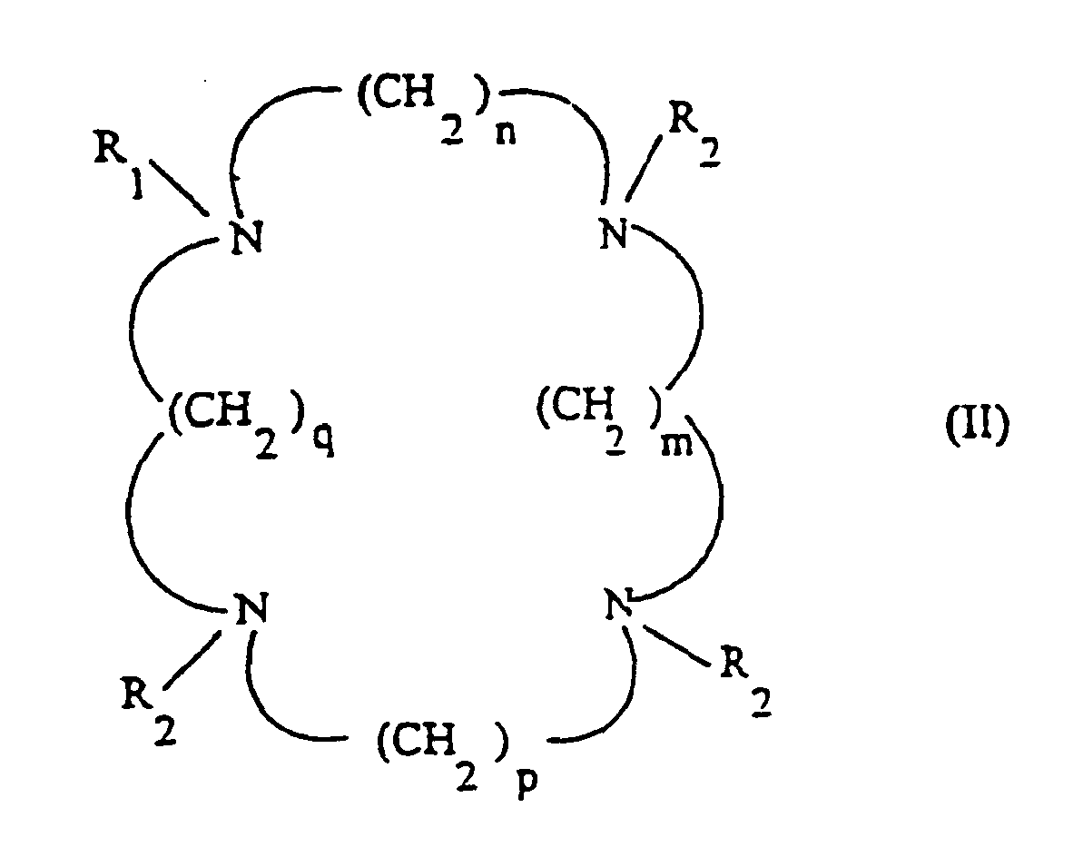

« Si hydroxy » signifiant :

et « Me » signifiant résine de Merrifield de formule :
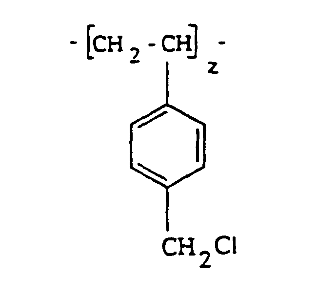
avec « Trp » signifiant : (CH2)2-COOH
« TrA » signifiant : CH2-COOH
et « TrMP » signifiant : CH2-PO3H.In the remainder of the description, the names of the polyazacycloalkanes according to the invention are in abbreviated form for simplification purposes. More specifically, the polyazacycloalkanes with four nitrogen atoms are referenced in the form "R1, a series of figures, R2" and correspond to the general formula:
"If hydroxy" means:
and "Me" means Merrifield resin of formula:
with "Trp" means: (CH 2 ) 2 -COOH
"TrA" meaning: CH 2 -COOH
and "TrMP" meaning: CH 2 -PO 3 H.
Lorsque aucune indication n'est précisée pour R2, cela signifie que R2 = H.When no indication is specified for R 2 , this means that R 2 = H.
Lorsque la suite de chiffres est 2222 ou 3333, cela signifie que n, m, p et q sont tous égaux respectivement à 2 ou à 3. Lorsque la suite de chiffre est 2323, cela signifie que n et p sont égaux à 2 et m et q sont égaux à 3 ou inversement que n et p sont égaux à 3 et m et q sont égaux à 2.When the sequence of digits is 2222 or 3333, it means that n, m, p and q are all equal to 2 or 3 respectively. is 2323, this means that n and p are 2 and m and q are 3 or vice versa that n and p are 3 and m and q are 2.
Les polyazacycloalcanes à 3 ou à 5 atomes d'azote sont référencés de façon similaire. Ainsi, la suite de chiffres 232 signifie que parmi n, m et p, deux de ces lettres représentent 2 et l'autre représente 3.The polyazacycloalkanes with 3 or 5 nitrogen atoms are referenced in a similar manner. Thus, the sequence of digits 232 means that among n, m and p, two of these letters represent 2 and the other represents 3.
Ainsi, les résines préférées utilisées dans le procédé de l'invention sont les résines suivantes :


La Si2323trPr est la résine préférée.Si2323trPr is the preferred resin.
Les résines mises en oeuvre dans le procédé selon l'invention peuvent être préparées par tout procédé adéquat.The resins used in the process according to the invention can be prepared by any suitable method.
Ainsi, les résines mises en oeuvre dans le procédé selon l'invention peuvent être préparées par le procédé décrit dans le document WO-A-96 11056, auquel on fait ici intégralement et explicitement référence et dont le contenu est intégralement inclus dans la présente description.Thus, the resins used in the process according to the invention can be prepared by the process described in the document WO-A-96 11056, to which reference is made here in full and explicitly and whose content is fully included in the present description. .
Le procédé décrit dans ce document consiste à faire réagir la silice avec un bras espaceur, puis, par exemple, avec un polyazacycloalcane, tel qu'un tétraazamacrocycle, et à réaliser ensuite la substitution des fonctions amines libres du macrocycle (polyazacycloalcane) par des groupes comportant notamment une fonction acide carboxylique.The process described in this document consists in reacting the silica with a spacer arm, then, for example, with a polyazacycloalkane, such as a tetraazamacrocycle, and then performing the substitution of the free amine functions of the macrocycle (polyazacycloalkane) with groups comprising in particular a carboxylic acid function.
La quantité de macrocycle greffé, suivant ce schéma de synthèse, est généralement d'environ 0,35 à 0,40 mmol.g de matériau. Ce premier procédé que nous appellerons pour la suite « voie 1 » a montré, lors de sa mise en oeuvre, que les étapes de la synthèse pouvaient être incomplètes.The amount of grafted macrocycle, according to this scheme of synthesis, is generally about 0.35 to 0.40 mmol.g of material. This first process, which we will call the "
En d'autres termes, cette voie de synthèse 1 présente deux inconvénients majeurs : seulement 30 à 50 % des bras espaceurs greffés dans la première étape réagissent avec le macrocycle. La quantité de macrocycles greffés s'en trouve ainsi considérablement réduite et la présence résiduelle des fonctions n'ayant pas réagi peut s'avérer préjudiciable lors de la mise en oeuvre d'un procédé, tel que celui de la présente invention, utilisant les matériaux pour une application donnée.In other words, this
La N-fonctionnalisation du macrocycle, par exemple, du tétraazamacrocycle greffé, dernière étape de la synthèse, n'est pas quantitative car seulement une à deux fonctions amine secondaire sur les trois disponibles réagissent avec le réactif.N-functionalization of the macrocycle, for example, grafted tetraazamacrocycle, the last step in the synthesis, is not quantitative because only one to two secondary amine functions out of the three available react with the reagent.
En outre, il n'est pas exclu que certains macrocycles soient liés par deux atomes d'azote au gel de silice. Cette hétérogénéité nuit grandement à l'efficacité et à la sélectivité du gel de silice modifié.In addition, it is not excluded that certain macrocycles are linked by two nitrogen atoms to the silica gel. This heterogeneity greatly affects the effectiveness and selectivity of the modified silica gel.
C'est la raison pour laquelle il est proposé un autre procédé de greffage pour la préparation des résines mises en oeuvre dans le procédé de l'invention.This is the reason why it is proposed another grafting process for the preparation of the resins used in the method of the invention.
Ce procédé, dit procédé de la « voie 2 », diffère essentiellement du procédé de la « voie 1 » par le fait que l'on change l'ordre de chacune des étapes du greffage, en faisant, tout d'abord, réagir un macrocycle, polyazacycloalcane non substitué, tel que le cyclame ou le cyclène (et non la silice, comme dans le procédé de la « voie 1 ») avec un bras espaceur, puis en greffant ledit composé portant un bras espaceur sur la silice.This process, referred to as the "
Eventuellement, et de préférence, ledit composé (polyazacycloalcane) portant un bras espaceur (composé A) est tout d'abord fonctionnalisé préalablement à son greffage sur la silice, c'est-à-dire que l'on synthétise un macrocycle (polyazacycloalcane), par exemple, tétrasubstitué préalablement au greffage de celui-ci sur la silice.Optionally, and preferably, said compound (polyazacycloalkane) carrying a spacer arm (compound A) is first functionalized prior to its grafting on the silica, that is to say that a macrocycle is synthesized (polyazacycloalkane), for example, tetrasubstituted before grafting it on the silica.
Un exemple du procédé de la « voie 2 » sans fonctionnalisation préalable du composé portant le bras espaceur est donné ci-dessous, le composé de départ étant le cyclame et le bras espaceur répondant à la formule :


Dans ce schéma réactionnel, la dernière étape (flèche en pointillés) est facultative, elle permet de protéger les groupes silanols libres restant sur la silice.In this reaction scheme, the last step (dotted arrow) is optional, it makes it possible to protect the free silanol groups remaining on the silica.
L'iodopropyltriéthoxysilane est synthétisé simplement par action de NaI sur le chloropropyltriéthoxysilane commercial. L'iodopropyltriéthoxysilane en solution dans l'acétonitrile est alors ajouté goutte à goutte à une solution de cyclame dans l'acétonitrile au reflux en présence de Na2CO3. Le mélange réactionnel est maintenu au reflux pendant 24 h, le solvant est ensuite évaporé et du pentane est ajouté au résidu. Le cyclame en excès, insoluble, est filtré, le filtrat est concentré et le composé (A) est obtenu sans purification ultérieure avec un rendement de 50 %. Le greffage de (A) sur le gel de silice est réalisé au reflux du xylène pendant 4 jours. La quantité de macrocycles greffés est alors, par exemple, de 0,8 mmol.g de gel de silice modifié.Iodopropyltriethoxysilane is synthesized simply by the action of NaI on commercial chloropropyltriethoxysilane. The iodopropyltriethoxysilane dissolved in acetonitrile is then added dropwise to a solution of cyclam in refluxing acetonitrile in the presence of Na 2 CO 3 . The reaction mixture is refluxed for 24 h, the solvent is then evaporated and pentane is added to the residue. The excess cyclam, insoluble, is filtered, the filtrate is concentrated and the compound (A) is obtained without further purification in a yield of 50%. The grafting of (A) on the silica gel is carried out at reflux of xylene for 4 days. The amount of grafted macrocycles is then, for example, 0.8 mmol.g of modified silica gel.
Le composé (A) peut être éventuellement fonctionnalisé, puis greffé ensuite suivant le schéma :


Le composé A est agité pendant 4 jours à température ambiante dans l'acrylate d'éthyle. Après évaporation de l'acrylate d'éthyle et plusieurs lavages au pentane, le produit B est obtenu quantitativement. Le greffage de B sur le gel de silice est ensuite réalisé comme décrit plus haut. Le composé final est, selon la nomenclature utilisée dans la présente demande, la résine « Si2323trPr ».Compound A is stirred for 4 days at room temperature in ethyl acrylate. After evaporation of the ethyl acrylate and several washing with pentane, the product B is obtained quantitatively. The grafting of B on the silica gel is then carried out as described above. The final compound is, according to the nomenclature used in the present application, the resin "Si2323trPr".
La dernière étape de réaction avec HCl est toutefois facultative, le composé précédant à trois fonctions esters étant aussi susceptible d'être mis en oeuvre dans le procédé selon l'invention.The last reaction step with HCl is however optional, the compound having three ester functions being also capable of being used in the process according to the invention.
Il est bien évident que le procédé décrit ci-dessus peut être appliqué à tout macrocycle de départ non substitué connu, à tout bras espaceur, à tout support comportant des sites actifs, silanols ou autre, et que la réaction de fonctionnalisation peut être toute réaction connue de l'homme du métier.It is obvious that the method described above can be applied to any known unsubstituted starting macrocycle, to any spacer arm, to any support having active sites, silanols or other, and that the functionalization reaction can be any reaction. known to those skilled in the art.
Ainsi, différents bras espaceurs (contenant des motifs aromatiques, des fonctions ester ou amide) peuvent être utilisés, de même, le réactif électrophile utilisé lors de la N-fonctionnalisation peut aussi varier, permettant l'accès à un large éventail de gels de silice présentant une efficacité et une sélectivité optimales.Thus, different spacer arms (containing aromatic units, ester or amide functions) can be used, likewise the electrophilic reagent used during the N-functionalization can also vary, allowing access to a wide range of silica gels having optimum efficiency and selectivity.
Si on compare ce procédé à celui procédant par greffage du groupe espaceur sur le gel de silice, puis par fixation sur ce bras du ligand désiré, ce nouveau procédé permet généralement de doubler la quantité de tétraazamacrocycles greffés à la surface du gel de silice. On augmente ainsi, de manière significative, le nombre de « sites actifs » par unité de surface et une amélioration considérable de l'efficacité du matériau en découle. Le deuxième avantage, plus important encore, est de pouvoir contrôler totalement la nature du ligand fixé, puisqu'il est synthétisé, isolé et caractérisé avant greffage.If this process is compared with that carried out by grafting the spacer group on the silica gel, then by fixing the desired ligand on this arm, this new method generally makes it possible to double the amount of tetraazamacrocycles grafted onto the surface of the silica gel. This increases, so significantly, the number of "active sites" per unit area and a considerable improvement in the efficiency of the material ensues. The second advantage, more importantly, is to be able to completely control the nature of the ligand attached, since it is synthesized, isolated and characterized before grafting.
Ce nouveau procédé de synthèse des ligands porteurs du bras espaceur ne nécessite pas de conditions expérimentales particulières et conduit avec des rendements convenables aux composés attendus sans purification ultérieure. En outre, cette synthèse est réalisée en une seule étape et non deux comme dans le procédé faisant intervenir l'hydrosilylation de l'alcène terminal. Enfin, la N-substitution de ces ligands est quantitative et permet le greffage de macrocycles totalement N-substitués.This novel process for the synthesis of the ligands carrying the spacer arm does not require any particular experimental conditions and leads with suitable yields to the expected compounds without subsequent purification. In addition, this synthesis is carried out in a single step and not two as in the process involving the hydrosilylation of the terminal alkene. Finally, the N-substitution of these ligands is quantitative and allows the grafting of totally N-substituted macrocycles.
En d'autres termes, le procédé de la « voie 2 » possède l'avantage de pouvoir préparer et caractériser le macrocycle tétrasubstitué par les techniques classiques de la chimie organique. Ce mode de greffage permet, d'une part, d'être certain que le macrocycle greffé est bien porteur, par exemple, de trois bras « acide carboxylique » (ces fonctions ont un rôle primordial dans la complexation des actinides) et, d'autre part, au moins de doubler la quantité de macrocycle greffée par unité de masse (voir tableau I).In other words, the "
Ainsi, les différentes quantités de macrocycles greffées pour diverses résines ont été déterminées par analyse élémentaire. Les résultats sont regroupés dans le tableau I, qui fait clairement apparaître que les résines préparées par le procédé de la « voie 2 » ont une quantité de macrocycle greffée nettement supérieure à celle des résines préparées par le procédé de la « voie 1 ».
De manière générale, si la quantité de polyazacycloalcane greffé par unité de masse de support, grâce aux procédés des « voies 1 et 2 » est généralement de 0,1 à plusieurs mmol.g-1, de préférence cette quantité doit être la plus élevée possible.In general, if the amount of polyazacycloalkane grafted per unit mass of support, using the methods of "
La quantité de polyazacycloalcane greffée par unité de masse obtenue par le procédé de la « voie 2 » est en outre, comme indiquée plus haut, nettement supérieure à celle de la « voie 1 », elle est donc généralement supérieure à 0,4 mmol.g-1, de préférence supérieure ou égale à 0,6 mmol.g-1, de préférence encore supérieure ou égale à 0,8 mmol.g-1.The amount of polyazacycloalkane grafted per unit mass obtained by the "
Le procédé de la « voie 2 » est décrit dans le brevet français FR-A-2 774 092 (n° de demande 98 00784), auquel il est fait ici intégralement et explicitement référence et dont le contenu est intégralement inclus dans la présente description.The method of "
L'invention a également trait à l'installation pour la mise en oeuvre du procédé selon l'invention.The invention also relates to the installation for implementing the method according to the invention.
Une telle installation pour l'élimination des cations métalliques contenus dans un liquide comprend essentiellement au moins un récipient, tel qu'une colonne remplie ou garnie d'une résine échangeuse d'ions chélatante constituée d'un polyazacycloalcane fixé sur un support, des moyens pour faire traverser ladite colonne par un courant de liquide à traiter, des moyens pour conditionner ladite résine à un pH de 4 à 6 et des moyens pour chauffer ladite résine à une température supérieure ou égale à 60°C.Such an installation for the removal of metal cations contained in a liquid essentially comprises at least one container, such as a column filled or lined with a chelating ion exchange resin consisting of a polyazacycloalkane attached to a support, means to pass through said column by a stream of liquid to be treated, means for conditioning said resin to a pH of 4 to 6 and means for heating said resin to a temperature greater than or equal to 60 ° C.
L'installation peut comprendre, en outre, des moyens pour régénérer ladite résine.The installation may further comprise means for regenerating said resin.
Avantageusement, l'installation selon l'invention comprend, en outre, un récipient, tel qu'une colonne remplie d'un échangeur d'ions ou d'un adsorbant organique ou minéral différent de ladite résine polyazacycloalcane greffée sur un support, placée en amont (par rapport au sens de circulation du courant de liquide à traiter) de ladite colonne remplie de résine.Advantageously, the plant according to the invention further comprises a vessel, such as a column filled with an ion exchanger or an organic or inorganic adsorbent different from said polyazacycloalkane resin grafted onto a support, placed in upstream (with respect to the direction of flow of the liquid stream to be treated) of said column filled with resin.
L'installation, selon l'invention, comprendra aussi, en outre, de préférence, des moyens de régénération dudit échangeur d'ions ou adsorbant.The plant according to the invention will also preferably also comprise means for regenerating said ion exchanger or adsorbent.
D'autres caractéristiques et avantages de l'invention apparaîtront mieux à la lecture de la description et des exemples suivants, donnés à titre illustratif et non limitatif.Other features and advantages of the invention will appear better on reading the following description and examples, given by way of illustration and not limitation.
Cette description est faite en référence aux dessins joints, dans lesquels :
- la figure 1 est une vue schématique en coupe verticale d'une installation pour la mise en oeuvre du procédé selon l'invention, convenant, plus particulièrement, à un traitement des effluents en aval de l'évaporateur industriel, comprenant deux colonnes respectivement remplies de silice et de résine polyazacycloalcane fixé sur silice ;
- la figure 2 est une vue schématique en coupe verticale d'une installation pour la mise en oeuvre du procédé selon l'invention, au stade du laboratoire, convenant plus particulièrement à un traitement des effluents en amont de l'évaporateur industriel ;
- la figure 3 est un graphique qui montre l'effet de la température sur l'extraction de l'uranimum (VI) à
un pH de 5 et pour une durée de 18 h.
- FIG. 1 is a diagrammatic view in vertical section of an installation for carrying out the process according to the invention, which is more particularly suitable for effluent treatment downstream of the industrial evaporator, comprising two columns respectively filled with silica and polyazacycloalkane resin attached to silica;
- Figure 2 is a schematic vertical sectional view of an installation for carrying out the method according to the invention, at the laboratory stage, more particularly suitable for effluent treatment upstream of the industrial evaporator;
- Figure 3 is a graph showing the effect of temperature on the extraction of uranimum (VI) at a pH of 5 and for a duration of 18 hours.
En abscisse est portée la température T(°C) et en ordonnée est porté le coefficient de partage statique Kds (ml/g), la courbe en traits pointillés est relative à un gel de silice témoin et la courbe en trait plein est relative à la résine Si2323trPr (« voie 1 ») ;
- la figure 4 est une vue schématique en coupe verticale du dispositif utilisé pour les essais en mode dynamique ;
- la figure 5 est un graphique qui donne le profil d'élution « type » de l'uranium à travers une colonne remplie de gel de silice modifié. En ordonnée, est portée la concentration C en uranium en sortie de colonne et en abscisse est porté le volume de solution élué V ;
- la figure 6 est un graphique qui donne le coefficient de partage dynamique Kdd(l) pour la résine Si2323trPr («
voie 1 ») (I) et pour le gel de silice témoin en fonction du pH (T = 25°C, incertitude ± 10 %) ; - la figure 7 est un graphique qui donne le coefficient de partage dynamique Kdd(l) pour les résines Si2323trPr («
voie 1 ») (I) et Si2323trPr («voie 2 ») (II) àpH 4, et pour le gel de silice témoin à pH = 9, en fonction de la température T(°C) (incertitude ± 10 %) ; - la figure 8 est un graphique qui représente le profil d'élution de l'uranium (VI) à partir d'une colonne remplie de Si2323trPr («
voie 2 »), à l'aide d'une solution d'acide nitrique 2N et à température ambiante.
- Figure 4 is a schematic vertical sectional view of the device used for dynamic mode testing;
- Figure 5 is a graph which gives the "typical" elution profile of uranium through a column filled with modified silica gel. On the ordinate is carried the uranium concentration C at the column outlet and on the abscissa is carried the volume of eluted solution V;
- FIG. 6 is a graph which gives the dynamic partition coefficient Kd d (1) for the Si2323trPr ("
lane 1") resin (I) and for the control silica gel as a function of the pH (T = 25 ° C., uncertainty ± 10%); - FIG. 7 is a graph which gives the dynamic partition coefficient Kd d (1) for the resins Si2323trPr ("
lane 1") (I) and Si2323trPr ("lane 2") (II) atpH 4, and for the gel control silica at pH = 9, as a function of temperature T (° C) (uncertainty ± 10%); - FIG. 8 is a graph which represents the elution profile of uranium (VI) from a column filled with Si2323trPr ("
lane 2"), using a 2N nitric acid solution and at room temperature.
En ordonnée, est portée la concentration en uranium, C en g/l, et en abscisse est porté le volume de HNO3 (V) éluée en ml ;
- la figure 9 est un graphique qui illustre les quantités d'uranium fixées (bandes rayées) et relarguées (bandes blanches) en mmol.g pour 5 expériences réalisées avec le matériau Si2323trPr («
voie 2 ») (incertitudes ± 10 %).
- FIG. 9 is a graph which illustrates the quantities of uranium fixed (striped strips) and released (white stripes) in mmol.g for 5 experiments with Si2323trPr material ("
lane 2") (uncertainties ± 10%).
La figure 1 est un exemple de réalisation d'une installation pour la mise en oeuvre du procédé selon l'invention convenant, plus particulièrement, à un traitement des effluents en aval de l'évaporateur industriel comprenant deux colonnes, la première remplie de silice et la seconde remplie de résine, polyazacycloalcane fixé sur silice.FIG. 1 is an exemplary embodiment of an installation for carrying out the process according to the invention which is more particularly suitable for effluent treatment downstream of the industrial evaporator comprising two columns, the first filled with silica and the second filled with resin, polyazacycloalkane attached to silica.
Cet exemple d'installation selon l'invention comporte schématiquement les éléments suivants.
- Une cuve (1) de réception des effluents contaminés d'un volume, par exemple,
de 1,5 m3 munie de capteurs de niveaux haut et bas, d'un thermoplongeur (2), d'une sonde de température (3) et d'un système de brassage (non représenté). Avant réception, l'effluent est envoyé par une pompe (5) au travers d'un bol filtrant (6) muni de cartouches, par exemple de trois cartouches d'un diamètre de pore de 5 µm. - Un circuit de décontamination composé d'une pompe doseuse (7), d'un premier manomètre (8), d'une première colonne remplie de silice (9) qui est munie de colliers chauffants avec un système de régulation de la température, d'un second manomètre (10), d'un réchauffeur (11), d'une seconde colonne remplie, par exemple, de résine Si2323trPr (12), d'une sonde de température (13) et d'un débitmètre (14). Chaque colonne contient de l'ordre de 12 litres de résine. L'ensemble de la tuyauterie est, de préférence, en inox.
- Une cuve de réception des effluents traités (15) munie de capteurs de niveaux haut et bas.
- Un circuit d'élution composé d'une pompe péristaltique (16), d'une tuyauterie en inox (17, 18) et de deux bidons (19, 20).
- A tank (1) for receiving contaminated effluents with a volume of, for example, 1.5 m 3 provided with high and low level sensors, an immersion heater (2), a temperature probe (3) and a brewing system (not shown). Before reception, the effluent is sent by a pump (5) through a filter bowl (6) provided with cartridges, for example three cartridges with a pore diameter of 5 microns.
- A decontamination circuit consisting of a metering pump (7), a first pressure gauge (8), a first column filled with silica (9) which is provided with heating collars with a temperature control system, d. a second pressure gauge (10), a heater (11), a second column filled with, for example, Si2323trPr resin (12), a temperature sensor (13) and a flow meter (14). . Each column contains about 12 liters of resin. All the piping is preferably made of stainless steel.
- A treated effluent receiving tank (15) provided with high and low level sensors.
- An elution circuit composed of a peristaltic pump (16), a stainless steel pipe (17, 18) and two drums (19, 20).
L'installation comprend, en outre, sur la canalisation reliant la cuve (1) à la colonne (9), un filtre (22), une électrovanne (23), et une pompe doseuse (24). Des vannes manuelles (25) sont par ailleurs prévues aux entrées et sorties des deux colonnes (9) et (12). Un capteur de température (26) est placé sur la canalisation d'alimentation de la cuve de réception des effluents traités (15) et une pompe (27) peut prélever les effluents se trouvant dans cette cuve pour un rejet (28) après une analyse radiologique.The installation further comprises, on the pipe connecting the tank (1) to the column (9), a filter (22), a solenoid valve (23), and a metering pump (24). Manual valves (25) are also provided at the entrances and exits of the two columns (9) and (12). A temperature sensor (26) is placed on the feed pipe of the treated effluent receiving tank (15) and a pump (27) can collect the effluents in the tank for rejection (28) after an analysis. Radiation.
L'ensemble de l'installation est placé dans un bac de rétention muni de sondes d'inondation. Les systèmes de chauffage, les différentes sondes et les pompes sont asservis à un boîtier électrique.The entire installation is placed in a holding tank equipped with flood probes. The heating systems, the different probes and the pumps are controlled by an electrical box.
Le fonctionnement de l'installation de la figure 1 peut être décrit de la manière suivante :The operation of the installation of FIG. 1 can be described as follows:
Préalablement, l'effluent à traiter, acheminé, par exemple, par camion citerne, est entraîné par la pompe (5) à travers le filtre à cartouches (6), afin d'éliminer les impuretés et particules solides (boue, algues, etc.). En effet, les procédés d'extraction sur phase solide sont, d'une manière générale, très sensibles à l'encrassement et doivent être protégés en amont par un système de filtration. L'effluent « propre » est ensuite admis dans la cuve de réception des effluents contaminés (1).Beforehand, the effluent to be treated, conveyed for example by tanker truck, is driven by the pump (5) through the cartridge filter (6), in order to eliminate impurities and solid particles (mud, algae, etc.). .). Indeed, the solid phase extraction processes are, in general, very sensitive to fouling and must be protected upstream by a filtration system. The "clean" effluent is then admitted to the contaminated effluent receiving tank (1).
Le fonctionnement de l'installation peut se décomposer en deux phases :
- 1) Fixation : les effluents sont entraînés par la pompe doseuse (7) successivement à travers les deux colonnes (du bas vers le haut) (9) et (12), remplies respectivement de silice et de résine, par exemple, de résine Si2323trPr.
Selon l'invention, la température de l'effluent lors du passage sur la colonne de résine est, de préférence, de 60°C. Le chauffage de l'effluent est effectué simultanément à l'aide du thermoplongeur (2), des colliers chauffants et du réchauffeur (11). Le débit de l'effluent lors de cette phase de fixation est compris, par exemple, entre 30 et 60 l/h. L'effluent est ensuite récupéré dans la cuve de réception des effluents traités (15).
Si l'analyse radiologique (29) n'indique aucune trace de contamination, l'effluent est alors, par exemple, directement transféré vers l'évaporateur industriel (28) pour réaliser l'évaporation finale ou rejeté à l'environnement (28).
En cas de contamination, l'effluent est alors réinjecté en début de procédé dans la cuve de réception des effluents contaminés (1). - 2) Régénération : une solution d'acide nitrique, par exemple (1N) (19) est entraînée par la pompe péristaltique (16), indépendamment à travers la colonne désirée, à contre-courant (du haut vers le bas). Bien entendu, en raison de la capacité importante des résines et de la très faible activité des effluents à traiter, cette opération est très peu fréquente.
- 1) Fixing: the effluents are driven by the metering pump (7) successively through the two columns (from bottom to top) (9) and (12), respectively filled with silica and resin, for example resin Si2323trPr .
According to the invention, the temperature of the effluent during the passage over the resin column is preferably 60 ° C. The heating of the effluent is carried out simultaneously using the immersion heater (2), heating collars and the heater (11). The flow rate of the effluent during this fixing phase is, for example, between 30 and 60 l / h. The effluent is then recovered in the receiving tank of the treated effluents (15).
If the radiological analysis (29) indicates no trace of contamination, the effluent is then, for example, directly transferred to the industrial evaporator (28) to achieve the final evaporation or released to the environment (28) .
In the event of contamination, the effluent is then reinjected at the beginning of the process in the receiving tank of the contaminated effluents (1). - 2) Regeneration : a solution of nitric acid, for example (1N) (19) is driven by the peristaltic pump (16), independently through the desired column, against the current (from top to bottom). Of course, because of the high capacity of the resins and the very low activity of the effluents to be treated, this operation is very infrequent.
Les résines, en fin de régénération, nécessitent un reconditionnement avant d'entamer un nouveau cycle. Le reconditionnement s'effectue par injection d'eau, d'une solution tampon à pH 4,7, puis d'un dernier rinçage à l'eau, en utilisant le même circuit.The resins, at the end of regeneration, require repackaging before starting a new cycle. Reconditioning is carried out by injecting water, a buffer solution at pH 4.7, and then a final rinsing with water, using the same circuit.
Dans les exemples qui suivent, on met en évidence le rôle de la température et du pH de conditionnement, ainsi que de la nature du ligand sur les capacités des résines de polyazacyclohexane greffés sur silice.In the following examples, the role of temperature and pH of conditioning, as well as the nature of the ligand on the capacities of polyazacyclohexane resins grafted on silica is highlighted.
On effectue tout d'abord une étude en mode statique, puis une étude en mode dynamique.First of all, a study in static mode and then a dynamic mode study.
Dans cet exemple, on étudie en mode statique, la capacité des résines utilisées dans le procédé de l'invention pour piéger l'uranium. Cette capacité et déterminée par des expériences en « batch » avec mise en contact du séquestrant en présence d'un excès de sel dans des conditions déterminées, notamment de pH et de température.In this example, the ability of the resins used in the process of the invention to trap uranium is studied in static mode. This capacity is determined by "batch" experiments with contacting the sequestering agent in the presence of an excess of salt under specific conditions, in particular pH and temperature.
Le mode opératoire des essais en mode statique est le suivant.The operating mode of the static mode tests is as follows.
Une masse connue (environ 100 mg) de résine séchée sous vide est placée dans une fiole contenant 10 ml d'une solution à 1 g.l-1 de nitrate d'uranyle à pH 5. L'ensemble est agité à température constante pendant 18 h. Ensuite, la résine est filtrée et rinçée avec de l'eau distillée. Le filtrat et les eaux de rinçage sont collectés et ajustés à 50 ml dans une fiole jaugée. La concentration en U(VI) est déterminée par ICP-AES. La quantité d'U(VI) fixée est calculée par rapport à la concentration en U(VI) avant et après l'extraction.A known mass (about 100 mg) of vacuum dried resin is placed in a flask containing 10 ml of a solution of 1 gl -1 of uranyl nitrate at
Pour chaque silice modifiée, deux expériences sont réalisées.For each modified silica, two experiments are carried out.
La capacité totale est calculée en considérant la quantité d'uranium extraite, par rapport à la masse de résine et au volume de la solution par l'intermédiaire du coefficient de partage statique Kds.The total capacity is calculated by considering the amount of uranium extracted, relative to the mass of resin and the volume of the solution via the static partition coefficient Kd s .
Pour chaque expérience réalisée, le coefficient de partage statique, Kds, est calculé selon la formule suivante : 

- [Co] =
- concentration de la solution avant extraction (g.ml-1)
- [C] =
- concentration de la solution après extraction (g.ml-1)
- V =
- volume de la solution (ml)
- m =
- masse de résine (g)
- [C o ] =
- concentration of the solution before extraction (g.ml -1 )
- [C] =
- concentration of the solution after extraction (g.ml -1 )
- V =
- volume of the solution (ml)
- m =
- resin mass (g)
Le coefficient de partage Kds reflète directement la capacité du matériau à fixer le métal. Ce coefficient de partage peut à priori être infini, mais est souvent égal à quelques centaines, voire parfois même quelques milliers.The partition coefficient Kd s directly reflects the ability of the material to fix the metal. This share coefficient can be infinite, but is often equal to a few hundred, sometimes even a few thousand.
Dans cet exemple, on étudie l'effet de la température sur l'extraction de l'uranium VI. Le mode opératoire est celui décrit plus haut, mais, de plus, la solution est chauffée durant l'extraction.In this example, we study the effect of temperature on the extraction of uranium VI. The procedure is as described above, but, in addition, the solution is heated during extraction.
On détermine ainsi les coefficients de partage statique obtenus pour un gel de silice de type KIESELGEL® (MERCK®), qui fait office de témoin et pour la résine Si2323trPr (préparée par le procédé de la « voie 1 »), en fonction de la température, le pH étant maintenu constant à une valeur de 5.The static partition coefficients obtained for a KIESELGEL® type silica gel (MERCK®), which serves as a control, are thus determined and for the Si2323trPr resin (prepared by the "
Les résultats obtenus sont regroupés sur la figure 3, où l'on a porté le coefficient de partage Kds (ml/g) en fonction de T(°C). La courbe en trait plein est relative à la résine Si2323trPr (« voie 1 ») et la courbe en traits pointillés est relative au gel de silice.The results obtained are grouped together in FIG. 3, where the partition coefficient Kd s (ml / g) is plotted as a function of T (° C). The solid line curve is relative to the Si2323trPr resin ("
Cette étude montre que pour le gel de silice, la température n'a pratiquement aucune influence sur l'adsorption de l'uranium, c'est-à-dire que la cinétique est rapide, alors que pour la silice modifiée Si2323trPr (obtenue par le procédé de la « voie 1 »), l'augmentation de la température provoque un accroissement considérable de l'efficacité de la résine, ce résultat traduit que la vitesse de la réaction de complexation est lente.This study shows that for silica gel, the temperature has almost no influence on the adsorption of uranium, that is to say that the kinetics is fast, whereas for the modified silica Si2323trPr (obtained by the method of "
L'extraction de l'U(VI) à 80°C, avec cette résine, permet de retenir, en statique, près de 90 % d'U(VI) (Kds = 784).The extraction of U (VI) at 80 ° C, with this resin, makes it possible to retain, in the static state, nearly 90% of U (VI) (Kd s = 784).
Dans cet exemple, on étudie l'influence de la nature du ligand de la résine sur l'extraction de l'uranium VI.In this example, we study the influence of the nature of the ligand of the resin on the extraction of uranium VI.
Les coefficients de partage statique de différents types de silices modifiées, synthétisées, ont été déterminés en suivant le mode opératoire décrit plus haut. Le pH étant maintenu égal à 5 et la température à 80°C. A titre de comparaison, on a déterminé, dans les mêmes conditions, les coefficients de partage statique d'un gel de silice et de la résine chélatante commerciale AMBERLITE® IRC718 (acide iminoacétique greffé sur polystyrène).The static partition coefficients of different types of modified, synthesized silicas were determined by following the procedure described above. The pH being maintained equal to 5 and the temperature to 80 ° C. For comparison, the static partition coefficients of a silica gel and commercial chelating resin AMBERLITE® IRC718 (iminoacetic acid grafted onto polystyrene) were determined under the same conditions.
Les résultats sont regroupés dans le tableau II, ci-dessous :
En raison de la quantité de macrocycles greffée élevée, la résine Si2323trPr, préparée selon le procédé de greffage, dit de la « voie 2 », possède le coefficient de partage le plus élevé.Due to the high amount of grafted macrocycles, the Si2323trPr resin, prepared according to the grafting method, referred to as "
La comparaison de ces résultats, avec ceux obtenus dans les mêmes conditions avec la résine chélatante commerciale AMBERLITE® IRC718, montre que ces nouvelles résines chélatantes sont de remarquables séquestrants de l'uranium (VI).The comparison of these results, with those obtained under the same conditions with the AMBERLITE® IRC718 commercial chelating resin, shows that these new chelating resins are remarkable sequestrants of uranium (VI).
On étudie, dans cet exemple, la capacité d'échange dynamique des résines.In this example, the dynamic exchange capacity of the resins is studied.
En effet, la capacité d'échange « statique » des résines est un paramètre important, mais pour un procédé réalisé en mode dynamique sur une colonne, la capacité d'échange « dynamique » est le paramètre qui traduit réellement les propriétés séquestrantes des résines étudiées.Indeed, the "static" exchange capacity of the resins is an important parameter, but for a process carried out dynamically on a column, the "dynamic" exchange capacity is the parameter that actually reflects the sequestering properties of the resins studied. .
Les tests ont été réalisés en mettant en oeuvre le dispositif représenté sur la figure 4 qui est composé sommairement d'une colonne (41), d'un diamètre de 10 mm et d'une hauteur de 300 mm, munie d'une jaquette de thermostatisation permettant de réguler la température à l'aide d'un bain thermostaté (43), et d'une pompe péristaltique (42) pour obtenir le débit souhaité.The tests were carried out using the device represented in FIG. 4 which is summarily composed of a column (41), with a diameter of 10 mm and a height of 300 mm, provided with a jacket of thermostatization to regulate the temperature using a thermostatic bath (43), and a peristaltic pump (42) to obtain the desired flow rate.
Environ 12 g de gel sont placés dans la colonne (41) après passage dans une solution d'eau distillée. Avant chaque essai, la résine est conditionnée à différents pH, en éluant 500 ml d'une solution tampon à travers la colonne, puis une solution d'eau distillée pour rincer la résine. Après ce traitement, la colonne est prête à l'utilisation.About 12 g of gel are placed in the column (41) after passing through a solution of distilled water. Before each test, the resin is conditioned at different pH, eluting 500 ml of a buffer solution through the column and then a solution of distilled water to rinse the resin. After this treatment, the column is ready for use.
Pour les tests de fixation, la solution à purifier (44) est éluée sur la colonne de bas en haut (flèche 46) à un débit de l'ordre de 100 ml.h-1. Les échantillons à analyser sont collectés (45) tous les 100 ml et la concentration en U(VI) est déterminée par ICP-AES. La solution est éluée sur la colonne jusqu'à ce que la fuite observée corresponde à la concentration de la solution mère.For the fixation tests, the solution to be purified (44) is eluted on the column from bottom to top (arrow 46) at a flow rate of the order of 100 ml.h -1 . The samples to be analyzed are collected (45) every 100 ml and the concentration of U (VI) is determined by ICP-AES. The solution is eluted on the column until the leak observed corresponds to the concentration of the stock solution.
Les tests de régénération sont réalisés en éluant 100 ml d'une solution d'acide nitrique 2N au même débit, mais du haut vers le bas de la colonne (flèche 47), immédiatement après les tests de fixation.The regeneration tests are carried out by eluting 100 ml of a 2N nitric acid solution at the same flow rate, but from the top to the bottom of the column (arrow 47), immediately after the fixing tests.
Un rinçage de la colonne est ensuite réalisé à l'aide d'une solution d'eau distillée. Les échantillons à analyser sont collectés tous les 10 ml et la concentration en U(VI) est déterminée par ICP-AES.Rinsing of the column is then carried out using a distilled water solution. The samples to be analyzed are collected every 10 ml and the concentration of U (VI) is determined by ICP-AES.
Pour chaque colonne de silice modifiée, deux expériences ont été réalisées.For each modified silica column, two experiments were performed.
La capacité d'échange « dynamique » dépend d'un nombre important de paramètres et, en particulier, de la concentration de la solution à extraire. Afin d'obtenir les courbes de saturation, qui donnent la variation de la concentration en uranium en sortie de colonne (C), en fonction du volume de solution éluée (V) (voir figure 5), une concentration en uranium, bien plus élevée que celles observées dans les effluents, a été choisie.The "dynamic" exchange capacity depends on a large number of parameters and, in particular, the concentration of the solution to be extracted. In order to obtain the saturation curves, which give the variation of the uranium concentration at the column outlet (C), as a function of the volume of solution eluted (V) (see FIG. 5), a much higher concentration of uranium is obtained. than those observed in the effluents, was chosen.
On considère généralement que le volume de saturation de la colonne est atteint (V1/2), lorsque la concentration en sortie est égale à la moitié de la concentration de la solution mère (Co/2).It is generally considered that the saturation volume of the column is reached (V 1/2 ), when the outlet concentration is equal to half of the concentration of the stock solution (C o / 2).
La mesure de la capacité en mode dynamique des résines, selon ce procédé, a été réalisée en calculant pour chaque expérience le coefficient de partage dynamique Kdd, selon la formule suivante : 

- [Co] =
- concentration de la solution avant extraction (g.ml-1)
- [C] =
- concentration de la solution après extraction (g.ml-1)
- V =
- volume de la solution (ml)
- M =
- masse de résine (g)
- [C o ] =
- concentration of the solution before extraction (g.ml -1 )
- [C] =
- concentration of the solution after extraction (g.ml -1 )
- V =
- volume of the solution (ml)
- M =
- resin mass (g)
Le Kdd est calculé d'après la courbe de saturation obtenue quand C = Co/2 : 
Il convient de mentionner que la courbe de saturation permet également de calculer la masse d'uranium retenue, qui est approximativement égale à V1/2 x So.It should be mentioned that the saturation curve also makes it possible to calculate the mass of retained uranium, which is approximately equal to V 1/2 x S o .
Pour ces expériences, on a choisi de tester les résines Si2323trPr synthétisées selon les voies 1 et 2. La silice a été systématiquement choisie comme matériau témoin.For these experiments, it was chosen to test the Si2323trPr resins synthesized according to
Dans cet exemple, on étudie l'influence du pH de conditionnement des résines sur l'extraction de l'uranium (VI), à l'aide des résines mises en oeuvre dans le procédé de l'invention et à l'aide d'un gel de silice témoin. Le mode opératoire est celui indiqué ci-dessus.In this example, the influence of the conditioning pH of the resins on the extraction of uranium (VI) is studied using the resins used in the process of the invention and with the aid of a control silica gel. The procedure is that indicated above.
L'extraction de l'uranium est étudiée spécifiquement sur la résine Si2323trPr (préparée par le procédé de la « voie 1 ») pour une gamme de pH des solutions tampons du conditionnement allant de 2 à 9 (2,5 ; 4 ; 5 ; 7 et 9), la température étant constante et égale à 25°C.Uranium extraction is specifically investigated on the Si2323trPr resin (prepared by the "
Les résultats sont regroupés dans le tableau III.
Les résultats obtenus qui sont reportés sur la figure 6 permettent la détermination expérimentale du pH optimum qui est compris entre pH 4 et pH 5. Ce résultat est en bon accord avec l'étude thermodynamique de cette nouvelle classe de ligands.The results obtained, which are shown in FIG. 6, allow the experimental determination of the optimum pH which is between
Par ailleurs, il est surprenant de constater la très faible capacité de la silice en mode dynamique par rapport à ce qui était observé en mode statique. Le mode de piégeage de la silice s'effectuant essentiellement par simple adsorption physique, on peut supposer, qu'en mode dynamique, l'élution de la solution entraîne l'uranium adsorbé.Moreover, it is surprising to note the very low capacity of the silica in dynamic mode compared to what was observed in static mode. Since the mode of trapping silica is essentially a simple physical adsorption, it can be assumed that, in dynamic mode, the elution of the solution causes the adsorbed uranium.
Selon l'invention, pour accélérer la vitesse de complexation avec les résines mises en oeuvre, il est nécessaire d'opérer à une température élevée durant le procédé.According to the invention, in order to accelerate the rate of complexation with the resins It is necessary to operate at a high temperature during the process.
Dans cet exemple, on étudie donc l'influence de la température sur le coefficient de partage dynamique, à la fois sur la silice (témoin), et sur les résines Si2323trPr (« voie 1 ») et Si2323trPr (« voie 2 »). Le mode opératoire est celui décrit plus haut, le pH de conditionnement étant maintenu constant et égal à 4 pour la résine Si2323Pr et à 9 pour la silice. Les résultats obtenus sont regroupés dans le tableau IV et reportés sur la figure 7.
On note que le maintien de la colonne à 80°C permet d'augmenter considérablement et de manière surprenante l'efficacité des résines utilisées selon l'invention et que l'augmentation est comprise entre 50 % et 70 %, selon les cas.It is noted that the maintenance of the column at 80 ° C makes it possible to considerably and surprisingly increase the effectiveness of the resins used according to the invention and that the increase is between 50% and 70%, as the case may be.
Dans le meilleur des cas, c'est-à-dire pour l'utilisation de la résine Si2332trPr (« voie 2 »), le Kdd observé (324) correspond à la fixation de 0,33 mmol d'uranium par gramme de résine (79 mg d'uranium par gramme de résine).In the best case, that is to say for the use of Si2332trPr resin ("
Comme on l'a déjà évoqué précédemment, la simple utilisation de colonnes remplies de silice, quelles que soient les conditions d'utilisation, conduit à des résultats très médiocres.As already mentioned above, the simple use of columns filled with silica, whatever the conditions of use, leads to very poor results.
Cette étude en mode dynamique montre clairement que des résultats incomparablement meilleurs en termes d'efficacité d'extraction, représentée par la capacité, sont obtenus dans les plages spécifiques de pH de conditionnement et de température, du procédé selon l'invention. Les essais démontrent que le procédé selon l'invention permet d'atteindre une décontamination des effluents contaminés α, qui n'avait jamais été obtenue par les procédés de l'art antérieur.This dynamic mode study clearly shows that incomparably better results in terms of extraction efficiency, represented by the capacity, are obtained in the specific pH ranges of conditioning and temperature, of the method according to the invention. The tests demonstrate that the process according to the invention makes it possible to reach a decontamination of the contaminated effluents α, which had never been obtained by the processes of the prior art.
Dans le tableau V, on indique la quantité d'U fixé (mmol.g), selon les conditions du procédé.
La meilleure capacité est obtenue pour l'utilisation de la résine Si2332trPr (« voie 2 »), à 80°C et après conditionnement à pH 4.The best capacity is obtained for the use of the Si2332trPr resin ("
Cet exemple concerne des essais de régénération en mode dynamique des résines mises en oeuvre dans le procédé selon l'invention.This example concerns dynamic regeneration tests of the resins used in the process according to the invention.
Ces tests ont été réalisés, après avoir saturé par l'uranium, selon les conditions optimales d'utilisation, une colonne chargée de résine Si2323trPr (« voie 2 »). Après saturation, une solution d'acide nitrique 2 N est éluée au même débit, mais du haut vers le bas de la colonne, à température ambiante.These tests were carried out, after having saturated with uranium, according to the optimal conditions of use, a column loaded with resin Si2323trPr ("
Les profils d'élution (concentration en uranium (VI) en fonction du volume de HNO3 élué) obtenus pour chaque expérience, permettent de calculer la quantité d'uranium relarguée et donc le taux de régénération : 
A titre d'exemple, le profil d'élution type (figure 8) présente un pic d'élution très élevé observé vers le milieu du profil d'élution pour une concentration d'uranium atteignant 80 fois celle de la solution mère. Le taux de régénération calculé est proche de 100 % aux incertitudes près. On peut donc considérer que la récupération de l'uranium est quantitative.By way of example, the typical elution profile (FIG. 8) has a very high elution peak observed towards the middle of the elution profile for a uranium concentration up to 80 times that of the stock solution. The calculated regeneration rate is close to 100% to the uncertainties. So we can consider that the recovery of uranium is quantitative.
Une étude réalisée sur plusieurs cycles extraction/régénération consécutifs (figure 9) montre que dans tous les cas le relarguage de l'uranium est total et la régénération du matériau totale.A study carried out on several consecutive extraction / regeneration cycles (Figure 9) shows that in all cases the release of uranium is total and the regeneration of the total material.
Dans cet exemple, on réalise le traitement d'effluents réels du centre du CEA de VALDUC par une installation pilote selon l'invention comprenant deux colonnes. Cette installation est sensiblement analogue à celle de la figure 1 et son fonctionnement est également tel que décrit ci-dessus. Cette installation pilote est utilisée pour réaliser la décontamination ultime, c'est-à-dire un traitement en aval de l'évaporateur industriel.In this example, the actual effluent treatment of the center of the CEA VALDUC is carried out by a pilot plant according to the invention comprising two columns. This installation is substantially similar to that of Figure 1 and its operation is also as described above. This pilot plant is used to carry out the ultimate decontamination, that is to say a downstream treatment of the industrial evaporator.
Nous précisons ci-après les caractéristiques de l'installation pilote et les conditions opératoires mises en oeuvre. Celles-ci ont sensiblement les conditions optimales d'utilisation des résines précédemment définies en mode dynamique.We specify below the characteristics of the pilot plant and the operating conditions implemented. These have substantially the optimum conditions of use of previously defined resins in dynamic mode.
L'installation comporte une première colonne remplie de silice (12 litres) et une seconde colonne remplie de résine Si2323trPr.The plant has a silica-filled first column (12 liters) and a second column filled with Si2323trPr resin.
La cuve de réception des effluents contaminés a un volume de 1,5 m3, l'effluent avant réception passe au travers d'un bol filtrant muni de trois cartouches (diamètre de filtration 5 µm).The receiving tank of contaminated effluent has a volume of 1.5 m 3 , the effluent before reception passes through a filter bowl equipped with three cartridges (filter
La cuve de réception des effluents traités a également un volume de 1,5 m3.The treated effluent receiving tank also has a volume of 1.5 m 3 .
L'ensemble de l'installation est placé dans un bac de rétention de 3 m3.The entire installation is placed in a retention tank of 3 m 3 .
La température de l'effluent, lors du passage sur la colonne de résine Si2323trPr, est de 60°C.The temperature of the effluent, when passing over the Si2323trPr resin column, is 60 ° C.
Le débit de l'effluent, lors de la phase de fixation, est de 30 à 60 1/h. La régénération est réalisée avec une solution d'acide nitrique 1 N, à l'issue de laquelle les résines sont reconditionnées par une solution tampon à pH 4,7.The flow rate of the effluent, during the fixing phase, is 30 to 60 l / h. The regeneration is carried out with a 1 N nitric acid solution, at the end of which the resins are reconditioned with a buffer solution at pH 4.7.
Les résultats des essais avec notamment les activités, avant et après traitement par le dispositif de l'invention, sont regroupés dans le tableau VI.
L'effluent 1 provenait de l'écoulement accidentel d'une eau de pluie à travers un bâtiment. Cet effluent, qui n'avait subi aucun traitement préalable contenant, par ailleurs, de la boue, et des algues, des feuilles.
L'effluent 2 était un effluent qui n'avait pas pu être décontaminé de manière ultime par l'installation actuelle de traitement des effluents, mettant en oeuvre une évaporation et une microfiltration et correspondant à l'art antérieur.The
En effet, comme nous l'avons déjà signalé, cette dernière ne permet pas de décontaminer de manière ultime tous les types d'effluent. Le traitement de cet effluent a été rendu possible par l'installation de l'invention assurant une activité nulle.Indeed, as we have already pointed out, the latter does not allow to decontaminate ultimately all types of effluent. The treatment of this effluent was made possible by the installation of the invention ensuring zero activity.
L'effluent 3 était un effluent de très faible activité qui n'avait subit aucun traitement préalable particulier, tel qu'un traitement chimique ou une évaporation. Les effluents possédant ce type d'activité constituent une grande part des effluents d'un centre, tel que celui de VALDUC, en outre, le traitement direct de ce type d'effluent par le procédé selon l'invention constitue une alternative très intéressante qui peut être intégrée au sein de l'installation actuelle de traitement des effluents. Ce type de traitement permet notamment d'éviter l'étape d'évaporation qui est beaucoup plus lourde à mettre en oeuvre.
La diversité des effluents traités montre que l'installation selon l'invention est capable de réaliser la récupération de traces d'actinides de tous les types d'effluents de très faible activité produits par le centre de VALDUC.The diversity of the treated effluents shows that the installation according to the invention is capable of achieving the recovery of traces of actinides of all the types of very low-level effluents produced by the VALDUC center.
Ceci est un avantage important par rapport au procédé et à l'installation actuels, qui ne permet pas de décontaminer de manière ultime tous les types d'effluents.This is an important advantage over the current process and installation, which does not ultimately decontaminate all types of effluents.
Les volumes importants qui ont été traités par l'installation pilote de l'invention sont significatifs et permettent d'en démontrer la supériorité vis-à-vis de l'installation d'ultrafiltration, actuellement utilisée pour réaliser le traitement ultime en aval de la tour d'évaporation, aussi bien en termes d'efficacité, que de coûts d'investissement, de fonctionnement et de maintenance.The large volumes that have been processed by the pilot plant of the invention are significant and make it possible to demonstrate its superiority over the ultrafiltration plant, currently used to carry out the ultimate treatment downstream of the plant. evaporation tower, both in terms of efficiency, investment costs, operation and maintenance.
Dans cet exemple, son effectué, au stade du laboratoire en boîte à gants, divers essais pour traiter les effluents en amont de l'évaporateur industriel, à l'aide d'une installation selon l'invention.In this example, it is carried out, at the glove box laboratory stage, various tests to treat the effluents upstream of the industrial evaporator, using an installation according to the invention.
Cette installation, qui est comparable à celle de la figure 1, est toutefois légèrement modifiée, elle est décrite à la figure 2.This installation, which is comparable to that of Figure 1, however, is slightly modified, it is described in Figure 2.
A l'intérieur de la boîte à gants, l'installation expérimentale, conforme à la présente invention, est composée principalement des éléments suivants :
- une capacité (201) qui reçoit directement les effluents de la station de traitement du centre de VALDUC, une pompe volumétrique péristaltique (202), une capsule de filtration (203) avec un diamètre des pores
de 50 µm ; - deux colonnes de résine montées en série : une première colonne (204) remplie de silice (gel de silice) ou d'une résine de type polyacrylate (AMBERLITE® IRC86RF) et une seconde colonne (205) remplie de silice (gel de silice) modifiée par les polyazacycloalcanes, de préférence, il s'agit de la résine dénommée Si2323trPr, qui a été préparée soit par le procédé, dit «
voie 1 », soit par le procédé, dit «voie 2 ». Chaque colonne a un diamètre de 1 cm et une hauteur de 30 cm.
- a capacity (201) which directly receives the effluents from the center treatment plant of VALDUC, a peristaltic volumetric pump (202), a filtration capsule (203) with a pore diameter of 50 μm;
- two columns of resin mounted in series: a first column (204) filled with silica (silica gel) or a polyacrylate type resin (AMBERLITE® IRC86RF) and a second column (205) filled with silica (silica gel) modified by the polyazacycloalkanes, preferably it is the resin called Si2323trPr, which was prepared either by the method, said "
lane 1", or by the method, said "lane 2". Each column has a diameter of 1 cm and a height of 30 cm.
Chaque colonne contient 12 g de gel de silice ou de résine ;
- un thermostat à circulation pour maintenir la température des colonnes à 60°C ;
- une cuve (206) remplie d'HNO3 1N, d'eau distillée, ou de solution tampon, reliée à une pompe volumétrique péristaltique, pour réaliser respectivement la régénération et le conditionnement des résines de chacune des colonnes (204, 205) ;
- une cuve de récupération des éluats des colonnes (208) ;
- des vannes à 3 voies (209, 210, 211, 212) à l'entrée et à la sortie des colonnes.
- a circulating thermostat to maintain the temperature of the columns at 60 ° C;
- a tank (206) filled with 1N HNO 3 , distilled water, or buffer solution, connected to a peristaltic volumetric pump, for respectively regenerating and conditioning the resins of each of the columns (204, 205);
- a vessel for recovering column eluates (208);
- 3-way valves (209, 210, 211, 212) at the inlet and outlet of the columns.
L'effluent prélevé pour réaliser cette étude possède une activité radiologique totale d'environ 6,1 kBq/m3 (tableau VII) et une charge saline de 0,78 mg/l. Il n'a subi aucun traitement chimique préalable, tel que précipitation ou floculation. L'analyse panoramique (tableau IX) de cet effluent montre que les actinides ne représentent qu'une infime partie des éléments présents (< 1 ppm). Cet effluent contient très majoritairement des éléments alcalins et alcalino-terreux (99,29 %), principalement du Na (84,38 %), du Ca (11,01 %), du K (3,44 %) et du Mg (0,45 %). Cet effluent contient également du B (0,59 %) et quelques éléments métalliques (Ti, Ni, W, Al et Zn ; pour un total de 0,15 %).
Tout comme le fonctionnement de l'installation et de l'installation pilote selon l'invention, précédemment présentées, le fonctionnement de l'installation expérimentale peut être décomposée en deux phases :As the operation of the installation and the pilot installation according to the invention, previously presented, the operation of the experimental setup can be broken down into two phases:
Les effluents en provenance directe de la station de traitement des effluents de VALDUC sont introduits dans la boîte à gants, où ils sont déversés dans la capacité (201), puis repris par la pompe (202).The effluents directly from the effluent treatment plant of VALDUC are introduced into the glove box, where they are discharged into the capacity (201) and then taken up by the pump (202).
Après passage sur le filtre (203) permettant de se débarrasser des impuretés (poussières, particules,...), la solution transite à travers le lit de résines de chaque du bas vers le haut. La première colonne (204), comme on l'a déjà vue, remplie de silice ou d'une résine de type polyacrylate (AMBERLITE® IRC86RF) et la seconde colonne (205) remplie de silice modifiée par des macrocycles. Ces derniers s'écoulent en tête de colonne et sont récupérés dans la capacité (208), où des prélèvements réguliers sont effectués pour être analysés par spectrométrie α ou ICP-MS.After passing through the filter (203) to get rid of impurities (dust, particles, ...), the solution passes through the bed of resins from each bottom to top. The first column (204), as already seen, filled with silica or a polyacrylate resin (AMBERLITE® IRC86RF) and the second column (205) filled with silica modified with macrocycles. The latter flow at the top of the column and are recovered in the capacity (208), where regular samples are taken to be analyzed by α or ICP-MS spectrometry.
La régénération des résines s'effectue par élution d'acide nitrique 2N du haut vers le bas de la colonne. Les éluats sont récupérés dans la capacité (208), où des prélèvements réguliers sont effectués pour analyses. Les résines nécessitent ensuite un reconditionnement avant d'entamer un nouveau cycle. Celui-ci s'effectue par élution d'eau, puis d'une solution tampon à pH 4,7, toujours du haut vers le bas de la colonne.The regeneration of the resins is carried out by elution of 2N nitric acid from the top to the bottom of the column. The eluates are recovered in the capacity (208), where regular samples are taken for analysis. The resins then require repackaging before starting a new cycle. This is done by elution of water and then buffer solution at pH 4.7, always from the top to the bottom of the column.
Les trois combinaisons de résines suivantes ont été envisagées (tableau VIII).
Les résultats des essais effectués sont regroupés dans le tableau IX.The results of the tests carried out are summarized in Table IX.
Les profils d'élution observés montrent que l'effluents est totalement décontaminés pour un volume inférieur au volume de fuite en radioéléments (v = 1 litre environ). Des analyses panoramiques ont été réalisées juste avant ce volume de fuite, afin d'apprécier la sélectivité du procédé (voir le tableau IX).
Au vu de ces résultats :
- Les alcalins et alcalino-terreux sont très peu retenus par les systèmes (a) et (b), les taux d'épuration oscillent entre 8 et 19 % pour (a) et entre O et 7 % pour (b). La sélectivité des résines Si2323trPr est donc importante pour cette famille d'éléments et elle augmente sensiblement lorsqu'on passe d'une résine élaborée par la «
voie 1 » à une résine élaborée par la «voie 2 ».
- The alkalis and alkaline earths are very seldom retained by the systems (a) and (b), the purification rates oscillate between 8 and 19% for (a) and between 0 and 7% for (b). The selectivity of the Si2323trPr resins is therefore important for this family of elements and it increases substantially when switching from a resin developed by the "
lane 1" to a resin developed by the "lane 2".
Si la première colonne contient de la résine AMBERLITE® IRC86RF (c), l'effluent se retrouve presque totalement épuré en éléments alcalino-terreux (Ca, Mg, Sr et Ba), mais par contre, les taux d'épuration ne sont que de 21 et 30 % pour les éléments alcalins Na et K, respectivement.
- Les métaux de transition sont également très peu retenus par les systèmes (a) et (b), les taux d'épuration oscillent entre 5 et 12 % pour (a) et entre 0 et 4 % pour (b). La sélectivité des résines Si2323trPr est donc importante pour cette famille d'éléments et encore une fois, elle semble augmenter sensiblement lorsqu'on passe d'une résine élaborée par la voie 1 à une résine élaborée par
la voie 2.
- The transition metals are also very seldom retained by the systems (a) and (b), the purification rates oscillate between 5 and 12% for (a) and between 0 and 4% for (b). The selectivity of the Si2323trPr resins is therefore important for this family of elements and again, it seems to increase significantly when going from a resin produced by the
channel 1 to a resin produced by thechannel 2.
Si la première colonne contient de la résine AMBERLITE® IRC86RF (c), l'effluent se retrouve presque totalement épuré en Ti et W, mais par contre le taux d'épuration n'est que de 35 % pour le Ni.
- Le Zn et l'Al sont moyennement retenus sur les différentes colonnes : les taux d'épuration sont de l'ordre de 40 % dans tous les cas.
- Enfin, le B est légèrement retenu, avec des taux d'épuration identiques, de l'ordre de 15 %.
- The Zn and Al are averagely retained on the different columns: the purification rates are of the order of 40% in all cases.
- Finally, the B is slightly restrained, with identical purification rates, of the order of 15%.
Ces expériences montrent que ces résines possèdent une très bonne sélectivité, particulièrement vis-à-vis des alcalins, alcalino-terreux et métaux de transition. La sélectivité est encore plus marquée pour la résine Si2323trPr élaborée selon la « voie 2 », par rapport à la résine Si2323trPr, élaborée selon la « voie 1 ». Par ailleurs, le couplage de ces résines avec la résine AMBERLITE® IRC86RF permet d'épurer une bonne partie des alcalino-terreux et des métaux de transition.These experiments show that these resins have a very good selectivity, particularly with respect to alkalis, alkaline earths and transition metals. The selectivity is even more pronounced for the Si2323trPr resin prepared in "
Malgré cette sélectivité importante, la forte salinité des effluents (essentiellement en alcalins et alcalino-terreux) pris à ce niveau du cycle de traitement contribue à saturer rapidement les résines.Despite this important selectivity, the high salinity of the effluents (mainly alkali and alkaline earth) taken at this level of the treatment cycle contributes to saturate the resins rapidly.
Ainsi, pour les métaux de la série des actinides, ces expériences montrent qu'il est possible de traiter directement des effluents possédant ce niveau d'activité, malgré des volumes de fuite assez faibles observés (compris entre 50 et 75 volumes de colonne), imputables à cet effet de sel important (les actinides ne représentent qu'une fraction de ppm de la totalité des éléments). Cette étude montre que l'efficacité d'un tel procédé de traitement des effluents radioactifs dépend moins du niveau d'activité de l'effluent que de sa charge saline.Thus, for the metals of the actinide series, these experiments show that it is possible to directly treat effluents with this level of activity, despite relatively low leakage volumes observed (between 50 and 75 column volumes), attributable to this important salt effect (the actinides represent only a fraction of ppm of all the elements). This study shows that the effectiveness of such a process for the treatment of radioactive effluents depends less on the level of activity of the effluent than on its saline load.
Claims (35)
- Method for removal of metal cations contained in a liquid in which said liquid is brought into contact at a temperature higher than or equal to 60°C, with a chelating ion exchange resin formed from polyazacycloalkane grafted on a solid support, said resin having been conditioned, previously to said contacting, at a pH of 4 to 6.
- Method according to Claim 1 in which the contacting is carried out at a temperature of 60 to 80°C.
- Method according to Claim 1 in which the conditioning pH is 4 to 5.
- Method according to any one of Claims 1 to 3 in which the conditioning of said resin is carried out by contacting said resin with a buffer solution, especially aqueous, in which the pH is 4 to 6, possibly preceded and/or followed by a rinsing of the resin with a major solvent of the liquid to be treated, especially with distilled water.
- Method according to Claim 1 carried out continuously, said resin being placed in at least one column passed through by a current of liquid to be treated.
- Method according to Claim 1 comprising, in addition, a regeneration step of said resin, when the latter is saturated by the fixed metals.
- Method according to Claim 5 and Claim 6 in which said regeneration is carried out by passing a regeneration solution through the column(s) in the reverse direction from the direction of circulation of the liquid to be treated.
- Method according to Claim 7 in which said regeneration solution is chosen from the acid solutions, for example, nitric acid.
- Method according to Claim 7 or Claim 8 in which at the end of the regeneration step, said regeneration solution containing the metals initially fixed on the resin is treated to recover the metals.
- Method according to any one of Claims 1 to 9 comprising a prior step for treatment of the liquid by contacting with an ion exchanger or organic or mineral adsorbent different from said polyazacycloalkane resin grafted on a support.
- Method according to Claim 10 in which said adsorbent is chosen from the silica gels.
- Method according to Claim 10 in which said ion exchanger is chosen from resins of the polyacrylate type, resins of the AMBERLITE® type.
- Method according to Claim 10 in which said prior treatment step is carried out continuously, said ion exchanger or adsorbent being placed in at least one column passed through by a current of liquid to be treated and positioned upstream of said column filled with resin.
- Method according to Claim 11 in which said ion exchanger or adsorbent is regenerated when it is saturated by the fixed metals under the same conditions as the resin and at the same time as regeneration of the latter and with the same regeneration solution.
- Method according to Claim 1 in which said metal cations to be removed are metal cations chosen from transition metals, heavy metals, metals from group IIIA of the periodic table, lanthanides, actinides and alkaline-earth metals.
- Method according to Claim 13 in which said metal cations are chosen among the cations of U, Pu, Am, Ce, Eu, Al, Gd, Cr, Mn, Fe, Co, Ni, Cu, Zn, Ag, Cd, B, Au, Hg, Pb, As, Ca, Sr, Mg, Be, Ba and Ra.
- Method according to any one of Claims 1 to 16 in which the treated liquid is an aqueous liquid.
- Method according to any one of Claims 1 to 17 in which the treated liquid is a radioactive aqueous effluent with low activity.
- Method according to Claim 19 in which said effluent is the aqueous effluent with low activity originating from the industrial evaporator of the treatment installation of effluents from a nuclear installation.
- Method according to Claim 16 and Claim 17 in which the liquid is a biological fluid, such as blood and the cations removed are copper and aluminium.
- Method according to any one of Claims 1 to 20 in which said chelating ion exchange resin formed from polyazacycloalkane grafted on a solid support fulfils one of the three formulas (I), (II) and (III) below:


- Method according to any one of Claims 1 to 21 in which the solid support is an organic polymer that may or may not be crosslinked.
- Method according to Claim 22 in which the solid support is a residue of an organic polymer that may or may not be crosslinked with alkyl halide end, preferably alkyl chloride end.
- Method according to Claim 23 in which the solid support is a residue of chloromethyl polystyrene.
- Method according to Claim 24 in which the grain size distribution of said chloromethyl polystyrene is between 20 and 400 mesh and, preferably, between 20 and 70 mesh.
- Method according to Claim 21 in which R1 is a solid support derived from silica fulfilling formula:


- Method according to Claim 26 in which the grains size distribution of the solid support derived from silica is between 20 and 400 mesh and, preferably between 20 and 70 mesh.
- Method according to Claim 21 in which said resin is chosen from the following resins:


- Method according to Claim 1 in which said solid support is silica, and said resin is prepared by a method in which silica is reacted with a spacer arm, then with azacycloalkane and then the substitution of the free amine functions of the polyazacycloalkane is carried out by groups especially including a carboxylic function.
- Method according to Claim 1 in which said solid support is silica and said resin is prepared by a method in which first, an unsubstituted polyazacycloalkane, such as cyclam or cyclene is reacted with a spacer arm, then said polyazacycloalkane carrying a spacer arm is grafted on the silica.
- Method according to Claim 30 in which in addition, said polyazacycloalkane carrying a spacer arm is functionalized prior to its grafting on the silica.
- Method according to Claim 30 or Claim 31 in which the amount of polyazacycloalkane grafted per unit weight of solid support, such as silica is greater than 0.4 mmol.g-1.
- Installation for removal of metal cations contained in a liquid comprising at least a column filled with a chelating ion exchange resin formed from a polyazacycloalkane fixed on a support, means for causing a current of liquid to be treated to pass through said column, means for conditioning said resin at a pH of 4 to 6 and means for heating said resin to a temperature greater than or equal to 60°C.
- Installation according to Claim 33 comprising, in addition, a column filled with ion exchanger or organic or mineral adsorbent different from said polyazacycloalkane resin grafted on a support, placed upstream of said column filled with resin.
- Installation according to Claim 33 or Claim 34 comprising in addition, means for regenerating said chelating ion exchange resin and possibly, said ion exchanger or organic or mineral adsorbent.
Applications Claiming Priority (3)
| Application Number | Priority Date | Filing Date | Title |
|---|---|---|---|
| FR9910861 | 1999-08-27 | ||
| FR9910861A FR2797786B1 (en) | 1999-08-27 | 1999-08-27 | PROCESS AND INSTALLATION FOR REMOVAL OF METAL CATIONS FROM A LIQUID BY POLYAZACYCLOALKANE RESINS GRAFTED ON A SUPPORT |
| PCT/FR2000/002374 WO2001015806A1 (en) | 1999-08-27 | 2000-08-25 | Method and installation for eliminating metal cations from a liquid with polyazacycloalkane resins grafted on a support |
Publications (2)
| Publication Number | Publication Date |
|---|---|
| EP1218104A1 EP1218104A1 (en) | 2002-07-03 |
| EP1218104B1 true EP1218104B1 (en) | 2006-10-18 |
Family
ID=9549389
Family Applications (1)
| Application Number | Title | Priority Date | Filing Date |
|---|---|---|---|
| EP00958739A Expired - Lifetime EP1218104B1 (en) | 1999-08-27 | 2000-08-25 | Method and installation for eliminating metal cations from a liquid with polyazacycloalkane resins grafted on a support |
Country Status (11)
| Country | Link |
|---|---|
| US (1) | US7083732B1 (en) |
| EP (1) | EP1218104B1 (en) |
| JP (1) | JP5026648B2 (en) |
| CN (1) | CN1140352C (en) |
| AT (1) | ATE342770T1 (en) |
| AU (1) | AU7016600A (en) |
| CA (1) | CA2381853C (en) |
| DK (1) | DK1218104T3 (en) |
| FR (1) | FR2797786B1 (en) |
| RU (1) | RU2255806C2 (en) |
| WO (1) | WO2001015806A1 (en) |
Cited By (1)
| Publication number | Priority date | Publication date | Assignee | Title |
|---|---|---|---|---|
| FR2928144A1 (en) * | 2008-02-28 | 2009-09-04 | Centre Nat Rech Scient | MATERIALS FOR SOLID / LIQUID EXTRACTION OF CATIONS FROM HEAVY METALS BASED ON N-FUNCTIONALIZED POLYAZACYCLOALCANES SUPPORTED |
Families Citing this family (29)
| Publication number | Priority date | Publication date | Assignee | Title |
|---|---|---|---|---|
| US7731920B2 (en) * | 2005-06-03 | 2010-06-08 | Brookhaven Science Associates | System and method for separating tellurium from cadmium waste |
| FR2896705B1 (en) * | 2006-01-30 | 2008-12-05 | Commissariat Energie Atomique | PROCESS FOR THE SEPARATION IN AQUEOUS MEDIUM OF AT LEAST ONE ACTINIDE ELEMENT OF LANTHANIDE ELEMENTS BY COMPLEXATION AND MEMBRANE FILTRATION |
| FR2911340B1 (en) * | 2007-01-16 | 2009-04-17 | Commissariat Energie Atomique | MATERIAL COMPRISING POLYAZACYCLOALCANES, GRAFTED ON POLYPROPYLENE FIBERS, PROCESS FOR PREPARING THE SAME, AND METHOD FOR REMOVING METAL CATIONS FROM A LIQUID |
| JP2010022923A (en) * | 2008-07-17 | 2010-02-04 | Mitsubishi Chemicals Corp | Wastewater treatment method |
| EP2509922A2 (en) * | 2009-12-11 | 2012-10-17 | Chemseq Internatiopnal Ab | Methods and compositions for complex binding of metal ions |
| US9589690B2 (en) | 2010-12-15 | 2017-03-07 | Electric Power Research Institute, Inc. | Light water reactor primary coolant activity cleanup |
| US9214248B2 (en) * | 2010-12-15 | 2015-12-15 | Electric Power Research Institute, Inc. | Capture and removal of radioactive species from an aqueous solution |
| US8975340B2 (en) | 2010-12-15 | 2015-03-10 | Electric Power Research Institute, Inc. | Synthesis of sequestration resins for water treatment in light water reactors |
| JP6009218B2 (en) * | 2011-05-24 | 2016-10-19 | ローム アンド ハース エレクトロニック マテリアルズ エルエルシーRohm and Haas Electronic Materials LLC | Alpha particle emitter removal |
| JP5766589B2 (en) | 2011-11-16 | 2015-08-19 | 株式会社東芝 | Iodine adsorbent and water treatment column using iodine adsorbent |
| WO2014018420A1 (en) * | 2012-07-21 | 2014-01-30 | K-Technologies, Inc. | Processes for the removal and recovery of minor elements in wet-process phosphoric acid |
| CN102861556B (en) * | 2012-09-08 | 2014-05-14 | 浙江工商大学 | Preparation method of chelating adsorption function resin |
| CN104916342B (en) * | 2015-05-11 | 2017-11-17 | 中国科学院上海应用物理研究所 | A kind of method of the enriched uranium from the aqueous solution containing uranyl ion |
| RU2661213C1 (en) * | 2017-07-03 | 2018-07-13 | Тамара Васильевна Морозова | Sorbent on the basis of modified silica gel |
| US10942096B2 (en) * | 2017-09-07 | 2021-03-09 | Elemental Scientific, Inc. | Automated system for remote inline concentration of ultra-low concentrations in pure chemicals |
| KR102067551B1 (en) * | 2018-04-12 | 2020-01-17 | (주) 에프엔지리서치 | Compounds for remediating the contaminated soil or water |
| DE102018207900B3 (en) * | 2018-05-18 | 2019-08-14 | Framatome Gmbh | Nuclear fuel disposal system and method of removing nuclear fuel |
| US11391853B2 (en) | 2018-06-20 | 2022-07-19 | BWXT Isotope Technology Group, Inc. | System and method for evaluating elution efficiency and radiopurity of tc-99m generators |
| CN109317116B (en) * | 2018-09-26 | 2021-08-31 | 中国工程物理研究院核物理与化学研究所 | A kind of composite resin and preparation method thereof and recovery method of palladium in nitric acid medium |
| CN109250844A (en) * | 2018-10-11 | 2019-01-22 | 王泽红 | A kind of environment-protecting industrial sewage disposal device |
| CN109231629A (en) * | 2018-10-30 | 2019-01-18 | 中国工程物理研究院核物理与化学研究所 | The adsorbent equipment of uranium in a kind of aqueous solution |
| CN109231525A (en) * | 2018-10-30 | 2019-01-18 | 中国工程物理研究院核物理与化学研究所 | The adsorption method of uranium in a kind of aqueous solution |
| CN112485273B (en) * | 2020-11-11 | 2023-06-06 | 苏州热工研究院有限公司 | Device for collecting radioactive iron in water body and detection method |
| CN112619625A (en) * | 2020-11-25 | 2021-04-09 | 中国辐射防护研究院 | Re-impregnation method and device for radioactive iodine adsorption module adsorption material |
| EP4008714A1 (en) * | 2020-12-03 | 2022-06-08 | Universität Zürich | Cyclic tetrapeptides and metal complexes thereof |
| WO2022235769A1 (en) * | 2021-05-04 | 2022-11-10 | Sachem, Inc. | Strong binding metal-chelating resins using macrocycle molecules |
| CN113731515A (en) * | 2021-09-24 | 2021-12-03 | 蚌埠市天星树脂有限责任公司 | Regeneration method of waste cation exchange resin |
| CN116514154B (en) * | 2023-05-09 | 2025-01-14 | 西安电子科技大学 | Hydrophilic gadolinium hydroxide nano-sheet and preparation method thereof |
| CN117229445B (en) * | 2023-09-20 | 2024-04-09 | 南京大学 | A weak base anion exchange resin with high ion exchange capacity and its preparation method and application |
Family Cites Families (11)
| Publication number | Priority date | Publication date | Assignee | Title |
|---|---|---|---|---|
| US3985648A (en) * | 1974-06-27 | 1976-10-12 | Almag Pollution Control Corporation | Method and system for purifying liquid |
| FR2613718B1 (en) | 1987-04-10 | 1990-12-14 | Centre Nat Rech Scient | MONOFUNCTIONALIZED CYCLIC TETRAMINS, THEIR PREPARATION METHOD, THEIR POLYMERS AND THE USE THEREOF |
| US4943375A (en) * | 1987-09-04 | 1990-07-24 | Brigham Young University | The process of separating a selected ion from a plurality of other ions in a multiple ion solution by contacting the solution with a macrocyclic ligand bonded to silica which selectively complexes with the desired ion |
| US4931553A (en) * | 1988-05-11 | 1990-06-05 | Gill Devinder S | Platinum-polymer complexes and their use as antitumor agents |
| US5096724A (en) * | 1988-06-03 | 1992-03-17 | Aquanautics Corporation | Methods, compositions, and systems for ligand extraction |
| FR2633090B1 (en) | 1988-06-16 | 1992-07-31 | Cogema | PROCESS FOR SEPARATING USING CROWN ETHERS URANIUM AND PLUTONIUM FROM AN AQUEOUS MEDIUM FROM THE PROCESSING OF IRRADIATED NUCLEAR FUELS |
| FR2643370B1 (en) | 1989-02-22 | 1991-08-23 | Air Liquide | POLYAZOTO DERIVATIVES AND THEIR METAL COMPLEXES FOR USE IN FIXING OXYGEN |
| DE4021046A1 (en) * | 1989-09-02 | 1991-03-07 | Noell Gmbh | Removing radioactive caesium from solns. and suspensions etc. - by filtering, recycling retentate to batch containers, feeding permeate to ion exchange, and adding permeate to previous retentate |
| FR2656150B1 (en) | 1989-12-15 | 1994-04-15 | Matieres Nucleaires Cie Gle | PROCESS FOR RECOVERY USING A CROWN ETHER OF PLUTONIUM PRESENT IN SOLUTIONS SUCH AS AQUEOUS EFFLUENTS, CONCENTRATED SOLUTIONS OF FISSION PRODUCTS AND CONCENTRATED SOLUTIONS OF PLUTONIUM. |
| FR2725382B1 (en) * | 1994-10-05 | 1997-01-03 | Commissariat Energie Atomique | POLYAZACYCLOALCANES, TRI-, TETRA- OR PENTAAZAMACROCYCLIC COMPLEXES, PROCESS FOR MANUFACTURING SUCH SUBSTITUTED OR NON-SUBSTITUTED POLYAZACYCLOALCANES AND GRAFTS ON A SUPPORT AND USES OF POLYAZACYCLOALCANES |
| FR2725552B1 (en) * | 1994-10-05 | 1996-10-31 | Commissariat Energie Atomique | PROCESS FOR THE ALPHA PARTIAL DECONTAMINATION OF AN AQUEOUS EFFLUENT |
-
1999
- 1999-08-27 FR FR9910861A patent/FR2797786B1/en not_active Expired - Fee Related
-
2000
- 2000-08-25 EP EP00958739A patent/EP1218104B1/en not_active Expired - Lifetime
- 2000-08-25 WO PCT/FR2000/002374 patent/WO2001015806A1/en not_active Ceased
- 2000-08-25 JP JP2001520208A patent/JP5026648B2/en not_active Expired - Fee Related
- 2000-08-25 RU RU2002107678/15A patent/RU2255806C2/en not_active IP Right Cessation
- 2000-08-25 CN CNB008120951A patent/CN1140352C/en not_active Expired - Fee Related
- 2000-08-25 AT AT00958739T patent/ATE342770T1/en active
- 2000-08-25 US US10/069,565 patent/US7083732B1/en not_active Expired - Fee Related
- 2000-08-25 CA CA002381853A patent/CA2381853C/en not_active Expired - Fee Related
- 2000-08-25 DK DK00958739T patent/DK1218104T3/en active
- 2000-08-25 AU AU70166/00A patent/AU7016600A/en not_active Abandoned
Cited By (2)
| Publication number | Priority date | Publication date | Assignee | Title |
|---|---|---|---|---|
| FR2928144A1 (en) * | 2008-02-28 | 2009-09-04 | Centre Nat Rech Scient | MATERIALS FOR SOLID / LIQUID EXTRACTION OF CATIONS FROM HEAVY METALS BASED ON N-FUNCTIONALIZED POLYAZACYCLOALCANES SUPPORTED |
| WO2009112736A1 (en) * | 2008-02-28 | 2009-09-17 | Centre National De La Recherche Scientifique (C.N.R.S) | Materials for the solid/liquid extraction of heavy metal ions, containing supported n-functionalised polyazacycloalkanes |
Also Published As
| Publication number | Publication date |
|---|---|
| EP1218104A1 (en) | 2002-07-03 |
| AU7016600A (en) | 2001-03-26 |
| ATE342770T1 (en) | 2006-11-15 |
| RU2255806C2 (en) | 2005-07-10 |
| CN1140352C (en) | 2004-03-03 |
| DK1218104T3 (en) | 2007-02-19 |
| CA2381853C (en) | 2009-05-05 |
| CN1371305A (en) | 2002-09-25 |
| JP5026648B2 (en) | 2012-09-12 |
| FR2797786B1 (en) | 2001-10-05 |
| US7083732B1 (en) | 2006-08-01 |
| JP2003508197A (en) | 2003-03-04 |
| WO2001015806A1 (en) | 2001-03-08 |
| FR2797786A1 (en) | 2001-03-02 |
| CA2381853A1 (en) | 2001-03-08 |
Similar Documents
| Publication | Publication Date | Title |
|---|---|---|
| EP1218104B1 (en) | Method and installation for eliminating metal cations from a liquid with polyazacycloalkane resins grafted on a support | |
| JP3045148B2 (en) | Alginate gel water treatment agent and method for producing the same | |
| EP0731730B1 (en) | Polyazacycloalkanes, tri, tetra or pentaazamacrocyclic complexes grafted to a support | |
| US5179213A (en) | Macrocyclic ligands bonded to an inorganic support matrix and a process for selectively and quantitatively removing and concentrating ions present at low concentrations from mixtures thereof with other ions | |
| Choo et al. | Selective removal of cobalt species using nanofiltration membranes | |
| FR2560069A1 (en) | METHOD FOR TREATING SOLUTIONS CONTAINING TECHNETIUM | |
| EP1183400B1 (en) | Method for separating in an aqueous medium lanthanides and/or actinides by combined complexing-nanofiltration, and novel complexing agents therefor | |
| JP7220894B2 (en) | Metal adsorbent having dithiocarbamic acid group, method for producing the same, and method for extracting metal | |
| Liu et al. | In situ assembly of PB/SiO2 composite PVDF membrane for selective removal of trace radiocesium from aqueous environment | |
| Homma et al. | Virus concentration from sewage | |
| JP2012229998A (en) | Radioactive substance decontamination device and decontamination method, from radioactively contaminated water incorporating salt such as seawater | |
| Wu et al. | Radiation-induced grafting of polyethyleneimine onto cellulose triacetate membrane for separation of cesium ions from aqueous solution | |
| Maartens et al. | Removal of natural organic matter by ultrafiltration: characterisation, fouling and cleaning | |
| EP1349639B1 (en) | Method of separating isotopes | |
| JP2016156797A (en) | Method for removing strontium from contaminated water containing alkaline earth metals | |
| JPS6327797A (en) | Method for continuously or pseudo-continuously separating cesium ion from aqueous solution | |
| JPS63305297A (en) | Treatment of radioactive waste liquid | |
| RU2282906C2 (en) | Method for decontaminating radioactive aqueous solutions | |
| FR2708373A1 (en) | Treatment of radioactive liquids. | |
| EP0306420B1 (en) | Process for the purification of traces of radioactive elements generated during the stockpiling of uranium resulting from the processing of irradiated nuclear fuels | |
| JPH11183691A (en) | Method for treating liquid radioactive waste | |
| RU2172991C1 (en) | Composite material for cleaning polluted water media containing radionuclides | |
| RU2144225C1 (en) | Method for selective extraction and concentration of uranium and plutonium | |
| WO1996011478A1 (en) | METHOD FOR PARTIALLY α-DECONTAMINATING AN AQUEOUS EFFLUENT | |
| Langenhorst et al. | Cation exchangers on a sugar‐beet pulp base. Application for decontaminating radioactive waste water |
Legal Events
| Date | Code | Title | Description |
|---|---|---|---|
| PUAI | Public reference made under article 153(3) epc to a published international application that has entered the european phase |
Free format text: ORIGINAL CODE: 0009012 |
|
| 17P | Request for examination filed |
Effective date: 20020208 |
|
| AK | Designated contracting states |
Kind code of ref document: A1 Designated state(s): AT BE CH CY DE DK ES FI FR GB GR IE IT LI LU MC NL PT SE |
|
| AX | Request for extension of the european patent |
Free format text: AL;LT;LV;MK;RO;SI |
|
| RBV | Designated contracting states (corrected) |
Designated state(s): AT BE DK FI FR SE |
|
| REG | Reference to a national code |
Ref country code: DE Ref legal event code: 8566 |
|
| 17Q | First examination report despatched |
Effective date: 20050311 |
|
| GRAP | Despatch of communication of intention to grant a patent |
Free format text: ORIGINAL CODE: EPIDOSNIGR1 |
|
| GRAS | Grant fee paid |
Free format text: ORIGINAL CODE: EPIDOSNIGR3 |
|
| GRAA | (expected) grant |
Free format text: ORIGINAL CODE: 0009210 |
|
| AK | Designated contracting states |
Kind code of ref document: B1 Designated state(s): AT BE DK FI FR SE |
|
| RAP1 | Party data changed (applicant data changed or rights of an application transferred) |
Owner name: CENTRE NATIONAL DE LA RECHERCHE SCIENTIFIQUE Owner name: COMMISSARIAT A L'ENERGIE ATOMIQUE |
|
| RAP2 | Party data changed (patent owner data changed or rights of a patent transferred) |
Owner name: CENTRE NATIONAL DE LA RECHERCHE SCIENTIFIQUE Owner name: COMMISSARIAT A L'ENERGIE ATOMIQUE |
|
| REG | Reference to a national code |
Ref country code: SE Ref legal event code: TRGR |
|
| PLBE | No opposition filed within time limit |
Free format text: ORIGINAL CODE: 0009261 |
|
| STAA | Information on the status of an ep patent application or granted ep patent |
Free format text: STATUS: NO OPPOSITION FILED WITHIN TIME LIMIT |
|
| 26N | No opposition filed |
Effective date: 20070719 |
|
| PGFP | Annual fee paid to national office [announced via postgrant information from national office to epo] |
Ref country code: FI Payment date: 20130719 Year of fee payment: 14 Ref country code: DK Payment date: 20130722 Year of fee payment: 14 Ref country code: SE Payment date: 20130814 Year of fee payment: 14 Ref country code: AT Payment date: 20130719 Year of fee payment: 14 |
|
| PGFP | Annual fee paid to national office [announced via postgrant information from national office to epo] |
Ref country code: FR Payment date: 20130902 Year of fee payment: 14 |
|
| PGFP | Annual fee paid to national office [announced via postgrant information from national office to epo] |
Ref country code: BE Payment date: 20130830 Year of fee payment: 14 |
|
| REG | Reference to a national code |
Ref country code: DK Ref legal event code: EBP Effective date: 20140831 |
|
| REG | Reference to a national code |
Ref country code: SE Ref legal event code: EUG |
|
| REG | Reference to a national code |
Ref country code: AT Ref legal event code: MM01 Ref document number: 342770 Country of ref document: AT Kind code of ref document: T Effective date: 20140825 |
|
| PG25 | Lapsed in a contracting state [announced via postgrant information from national office to epo] |
Ref country code: BE Free format text: LAPSE BECAUSE OF NON-PAYMENT OF DUE FEES Effective date: 20140831 Ref country code: FI Free format text: LAPSE BECAUSE OF NON-PAYMENT OF DUE FEES Effective date: 20140825 |
|
| PG25 | Lapsed in a contracting state [announced via postgrant information from national office to epo] |
Ref country code: SE Free format text: LAPSE BECAUSE OF NON-PAYMENT OF DUE FEES Effective date: 20140826 Ref country code: AT Free format text: LAPSE BECAUSE OF NON-PAYMENT OF DUE FEES Effective date: 20140825 |
|
| REG | Reference to a national code |
Ref country code: FR Ref legal event code: ST Effective date: 20150430 |
|
| PG25 | Lapsed in a contracting state [announced via postgrant information from national office to epo] |
Ref country code: DK Free format text: LAPSE BECAUSE OF NON-PAYMENT OF DUE FEES Effective date: 20140831 |
|
| PG25 | Lapsed in a contracting state [announced via postgrant information from national office to epo] |
Ref country code: FR Free format text: LAPSE BECAUSE OF NON-PAYMENT OF DUE FEES Effective date: 20140901 |