EP1203846A1 - Composite thermal insulation system, and insulating elements and production method therefor - Google Patents
Composite thermal insulation system, and insulating elements and production method therefor Download PDFInfo
- Publication number
- EP1203846A1 EP1203846A1 EP01123408A EP01123408A EP1203846A1 EP 1203846 A1 EP1203846 A1 EP 1203846A1 EP 01123408 A EP01123408 A EP 01123408A EP 01123408 A EP01123408 A EP 01123408A EP 1203846 A1 EP1203846 A1 EP 1203846A1
- Authority
- EP
- European Patent Office
- Prior art keywords
- elements
- insulation
- plate
- insulating element
- element according
- Prior art date
- Legal status (The legal status is an assumption and is not a legal conclusion. Google has not performed a legal analysis and makes no representation as to the accuracy of the status listed.)
- Withdrawn
Links
- 238000009413 insulation Methods 0.000 title claims abstract description 233
- 239000002131 composite material Substances 0.000 title claims description 42
- 238000004519 manufacturing process Methods 0.000 title claims description 7
- 239000011505 plaster Substances 0.000 claims abstract description 29
- 239000011490 mineral wool Substances 0.000 claims abstract description 14
- 239000011230 binding agent Substances 0.000 claims abstract description 7
- 239000000853 adhesive Substances 0.000 claims description 37
- 230000001070 adhesive effect Effects 0.000 claims description 37
- 238000010276 construction Methods 0.000 claims description 16
- 239000000835 fiber Substances 0.000 claims description 16
- 239000004570 mortar (masonry) Substances 0.000 claims description 16
- 238000000034 method Methods 0.000 claims description 15
- 239000000463 material Substances 0.000 claims description 13
- 230000002787 reinforcement Effects 0.000 claims description 12
- 239000003365 glass fiber Substances 0.000 claims description 9
- 239000004033 plastic Substances 0.000 claims description 9
- 229920003023 plastic Polymers 0.000 claims description 9
- 239000004744 fabric Substances 0.000 claims description 8
- 239000002557 mineral fiber Substances 0.000 claims description 8
- 239000012774 insulation material Substances 0.000 claims description 4
- 229910052751 metal Inorganic materials 0.000 claims description 4
- 239000002184 metal Substances 0.000 claims description 4
- 229910052918 calcium silicate Inorganic materials 0.000 claims description 3
- 239000000378 calcium silicate Substances 0.000 claims description 3
- OYACROKNLOSFPA-UHFFFAOYSA-N calcium;dioxido(oxo)silane Chemical compound [Ca+2].[O-][Si]([O-])=O OYACROKNLOSFPA-UHFFFAOYSA-N 0.000 claims description 3
- 239000004568 cement Substances 0.000 claims description 3
- 238000004140 cleaning Methods 0.000 claims description 3
- 239000011810 insulating material Substances 0.000 claims description 3
- 150000002739 metals Chemical class 0.000 claims description 2
- 230000000149 penetrating effect Effects 0.000 claims description 2
- 229920001169 thermoplastic Polymers 0.000 claims description 2
- 229920001187 thermosetting polymer Polymers 0.000 claims description 2
- 239000004416 thermosoftening plastic Substances 0.000 claims description 2
- 238000003780 insertion Methods 0.000 claims 1
- 230000037431 insertion Effects 0.000 claims 1
- 239000011491 glass wool Substances 0.000 abstract 1
- 238000007373 indentation Methods 0.000 abstract 1
- 239000010410 layer Substances 0.000 description 20
- 241000446313 Lamella Species 0.000 description 5
- 238000012545 processing Methods 0.000 description 5
- 238000011161 development Methods 0.000 description 4
- 238000010586 diagram Methods 0.000 description 4
- 230000001419 dependent effect Effects 0.000 description 3
- 230000003014 reinforcing effect Effects 0.000 description 3
- 238000013459 approach Methods 0.000 description 2
- 238000009826 distribution Methods 0.000 description 2
- 238000005553 drilling Methods 0.000 description 2
- 230000000694 effects Effects 0.000 description 2
- 238000007639 printing Methods 0.000 description 2
- 230000007704 transition Effects 0.000 description 2
- 239000004793 Polystyrene Substances 0.000 description 1
- 239000012790 adhesive layer Substances 0.000 description 1
- 230000002411 adverse Effects 0.000 description 1
- 238000004873 anchoring Methods 0.000 description 1
- 238000005452 bending Methods 0.000 description 1
- 238000005253 cladding Methods 0.000 description 1
- 239000004567 concrete Substances 0.000 description 1
- 239000006260 foam Substances 0.000 description 1
- 239000011494 foam glass Substances 0.000 description 1
- 239000003292 glue Substances 0.000 description 1
- 238000010438 heat treatment Methods 0.000 description 1
- 229920002223 polystyrene Polymers 0.000 description 1
- 239000000758 substrate Substances 0.000 description 1
- 238000012546 transfer Methods 0.000 description 1
Images


Classifications
-
- E—FIXED CONSTRUCTIONS
- E04—BUILDING
- E04B—GENERAL BUILDING CONSTRUCTIONS; WALLS, e.g. PARTITIONS; ROOFS; FLOORS; CEILINGS; INSULATION OR OTHER PROTECTION OF BUILDINGS
- E04B1/00—Constructions in general; Structures which are not restricted either to walls, e.g. partitions, or floors or ceilings or roofs
- E04B1/62—Insulation or other protection; Elements or use of specified material therefor
- E04B1/74—Heat, sound or noise insulation, absorption, or reflection; Other building methods affording favourable thermal or acoustical conditions, e.g. accumulating of heat within walls
- E04B1/76—Heat, sound or noise insulation, absorption, or reflection; Other building methods affording favourable thermal or acoustical conditions, e.g. accumulating of heat within walls specifically with respect to heat only
- E04B1/762—Exterior insulation of exterior walls
Definitions
- the invention relates to a composite thermal insulation system consisting of plate-shaped Insulation elements, in particular from mineral fibers bound with binders, preferably made of glass fibers and / or rock wool, with a Construction adhesive, in particular adhesive mortar or another hydraulic adhesive and / or mechanical fastening elements penetrating the insulation elements on building surfaces, especially in the facade area of buildings attachable and in particular with a cover, for example a Cover plaster can be covered.
- a Construction adhesive in particular adhesive mortar or another hydraulic adhesive and / or mechanical fastening elements penetrating the insulation elements on building surfaces, especially in the facade area of buildings attachable and in particular with a cover, for example a Cover plaster can be covered.
- the invention relates to an insulating element for a composite thermal insulation system, in particular with binders bound mineral fibers, preferably made of glass fibers and / or rock wool, consisting of a parallelepiped with two large ones spaced apart and surfaces aligned parallel to one another and these with one another connecting side surfaces, preferably at right angles to each other and are aligned at right angles to the large surfaces.
- binders bound mineral fibers preferably made of glass fibers and / or rock wool
- Insulation elements are used for this, which consist of mineral fibers, for example.
- one Insulation layer consisting of insulation elements on the outer surfaces of the Building.
- effective subsequent thermal insulation can be provided.
- plaster layers or ventilated cladding arranged on the insulation elements.
- Insulation elements are used for the construction of composite thermal insulation systems made of expanded or extruded polystyrene, mineral wool, to a small extent Foam glass, aerated concrete or similar materials used.
- Mineral wool is due to the arrangement of the fibers in the Insulation body generally between insulation elements with predominantly laminar Differentiated structure and so-called lamella plates, in which a The grain runs at right angles to the large surfaces.
- Laminar structured dam elements have a lower transverse tensile strength perpendicular to the large surfaces, but a comparatively higher one Shear rigidity as lamella plates. By aligning the individual mineral fibers with the lamella plates predominantly perpendicular to the large surfaces a 3 to 5 times higher transverse tensile strength is achieved, but this is too clear shear-proof and less bending-resistant insulation elements.
- Another Difference between the insulation elements with a laminar structure and The lamellar panels are that the insulation elements with laminar Structure is usually manufactured and processed in larger formats, than the slat plates.
- the insulation elements with the substrate, i.e. the facade bonded.
- insulation elements made of hard foam and mineral wool
- an adhesive mortar applied all around and in the form of two approximately palm-sized chunks applied in the middle. This results in an adhesive surface of about 40% of a large surface of the insulation element.
- lamella plates are preferably covered over the entire surface with an adhesive provided, the proportion of the adhesive surface up to 50% of a large Surface of a slat plate can be reduced if the glue is in regular Strips, for example 50 mm wide, are applied to the lamella plate to ensure an even load transfer. It should be taken into consideration, that in both cases over the adhesive both the own load of the thermal insulation composite system as well as occurring wind suction have to. Insulation elements are used to achieve greater security of the fastening then secured by so-called insulation holders. On Insulation holder consists of a plastic plate with reinforcing ribs and a molded shaft that ends in a plastic dowel. The insulation holder is placed in the facade through the insulation board Drilled hole and then spread with a central metallic mandrel.
- the insulation layer made of the insulation elements applied a layer of plaster, usually with one of endless Glass fiber fabricated mesh is reinforced or reinforced.
- a layer of plaster usually with one of endless Glass fiber fabricated mesh
- Such Plaster layer is divided into a base plaster layer, which is a for cost reasons Material thickness of about 1 to 1.5 mm, so that in the base coat inserted reinforcement is partially exposed.
- a so-called plaster applied On top of the base plaster layer second layer of plaster, a so-called plaster applied, which is a material thickness of at least 2 to 3 mm.
- the top plaster layers can also Have material thicknesses of up to 20 mm, which increases the dead weight of the thermal insulation composite system naturally increased.
- the insulation holder with the reinforcement include.
- an optimal result is not achieved, because with a usual internal mesh size one used for the reinforcement
- the number of insulation holders is therefore dependent on the mechanical properties of the insulation material from the height of the building dependent wind suction load and the diameter of the insulation plate.
- Table 1 below shows the number of insulation holders required for low-strength mineral wool insulation elements, depending on the height of the building for the wall and building edges, the diameter of the dowel plates and the arrangement of the insulation material holders under or above the reinforcement. Rounding off the calculated specific requirement results in a certain leveling out.
- Edge areas extend over 1 to 2 m each measured from the corner of the building. Height range above ground in m 0 m ⁇ H ⁇ 8 m 8 m ⁇ H ⁇ 20 m 20 ⁇ H 100 m Position of the insulation layer in the wall surface area edge area edge area edge Wind suction load in kN / m 2 according to DIN 1055 0.35 1.00 0.56 1.60 0.77 2.20 Number of required insulation holders in pieces / m 2 attachment ... by reinforcement, plate diameter 6 cm 2 5 3 8th 4 11 ... under the reinforcement, plate diameter 14 cm 2 5 3 8th 4 11 ... under reinforcement, plate diameter 9 cm 2 6 4 10 5 14
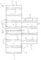
- FIG. 1b shows the arrangement of six insulation holders per m 2 , whereupon there is a need for seven insulation holders per m 2 in the edge area.
- FIG. 1c shows a diagram with eight insulation holders per m 2 and a resulting need for nine insulation holders per m 2 in the edge area.
- FIG. 1d also shows a fastening diagram with ten insulation holders per m 2 , which results in a required number of eleven insulation holders per m 2 in the edge area.
- FIG. 1e shows the arrangement of twelve insulation holders per m 2 . In this embodiment, twelve insulation holders per m 2 are also to be arranged in the edge area.
- the invention has for its object to provide a thermal insulation composite system or an insulation element and a method for producing a thermal insulation composite system, which avoids the disadvantages described above and in particular reduces the number of required insulation holder or the arrangement of the insulation holder in certain schemes to make it possible to identify an arrangement that is as uniform as possible, even if the applied plaster layers reveal the underlying insulation holder due to weather conditions.
- the insulation elements are fastened with a plurality of plate-shaped elements which overlap the insulation elements, the elements being arranged flush with the surface in depressions in the insulation elements and being connected to the building with the mechanical fastening elements.
- a composite thermal insulation system designed according to the teaching of the invention has the particular advantage that the plate-shaped elements Arrangement of mechanical fasteners, especially insulation holders is predetermined, so that there is an overall uniform arrangement of these Fasteners over the entire insulation surface results. Furthermore the plate-shaped elements offer the advantage that they are uniform Effect pressure distribution on the insulation elements. The flush The arrangement of the elements does not pose any additional requirements to the plaster systems to be applied, because of the surface-flush finish the plate-shaped elements with the surface of the insulation elements continue it is possible to apply thin base plasters, which are then applied are covered by usual finishing plasters.
- the insulation elements are preferably horizontal with their longitudinal axis of the building facade. This results in rows of insulation elements, which are in particular arranged such that between neighboring ones Insulation elements arranged between two joint surfaces of insulation elements of the insulation elements arranged above and / or below are arranged.
- each intumescent element several wells arranged at regular intervals has, which are arranged linearly in adjacent rows.
- each Insulation element thus has at least two depressions in the corresponding one plate-shaped elements can be inserted.
- the depressions of neighboring rows are arranged in such a way that the plate-shaped elements in at least two rows of insulation elements overlap to the through the fasteners applied pressure to at least two in adjacent rows to distribute arranged insulation elements.
- the insulation elements are on the construction site no further processing of the insulation elements is necessary because due to the prepared recesses, the insulation elements are positioned precisely in the Arranged in rows, i.e. can be glued to the facade before then the plate-shaped elements are inserted into the corresponding depressions and can be anchored to the facade with fasteners.
- the insulation elements cover the entire surface with a Reinforced plaster layer are covered, which consists of a basic plaster with a mesh consists of endless glass fibers and a finishing coat.
- a basic plaster with a mesh consists of endless glass fibers and a finishing coat.
- the recesses are parallel to two parallel side surfaces and perpendicular to two long sides that are also parallel run.
- This configuration takes into account that such Insulation elements are mostly laid horizontally.
- the wells therefore preferably run transversely to the longitudinal axis of the insulation elements and therefore extend in a vertical direction parallel to the fall line of the building.
- each recess is at an even distance from each other a short side surface is arranged. Because such insulation elements to avoid cross joints in the bond, this results from this with appropriate processing, a continuous arrangement of the individual Wells of neighboring insulation elements, so that the wells of the individual insulation elements linear over the entire insulation layer surface extend.
- the depressions are preferably arranged at uniform intervals from one another, to simplify the laying of the insulation elements appropriate alignment of the recesses in the thermal insulation composite system achieve. On the other hand, this also ensures a uniform application of force Insulation holder secured in the insulation elements.
- the depressions extend in particular across the entire width of the parallelepiped. It exists but also the possibility not to the wells in the edge area of the Continuing insulation elements.
- the plate-shaped elements preferably consist of fiber-reinforced calcium silicate plates, fiber cement plates and / or mineral wool plates with a high bulk density, the mineral wool plates preferably having a bulk density of approximately 700 to 1500 kg / m 3 .
- Such elements have a homogeneous pressure behavior, so that the pressure introduced into the elements by the insulation holders is evenly distributed.
- the plate-shaped Elements have a material thickness of 3 to 8 mm, the plate-shaped Elements preferably flush with the parallelepiped to lock. Adequate material thickness of the plate-shaped elements is required to prevent damage to the insulation holder if the pressure is uneven, in particular to avoid breaking the elements.
- the flush Conclusion offers the advantage that a plaster system with homogeneous material thickness can be applied. In particular, filling and Spackling in the area of the depressions avoided.
- the plate-shaped elements can according to a further feature of the invention preferably on their surfaces lying in parallelepiped with connected to a tear-resistant fabric, in particular glued. With this configuration it is not necessary to connect the plate-shaped elements with the insulation element connect directly. The stability of the insulation element is this improves overall, with tolerances due to a relative movement balanced between the plate-shaped elements and the insulation element can be.
- the plate-shaped elements preferably have openings, which in particular formed as bores and arranged at an equal distance from each other are.
- a load-bearing sleeve is inserted, which for example consists of Metal and / or plastic is formed. Through such sleeves there is another Improvement of the load introduction into the plate-shaped elements and thus into that Insulation element enables.
- the plate-shaped Elements are band-like and have a length that is greater is as the length of a depression. This ensures that the plate-shaped Elements over the edge area of the insulation element in the area of the neighboring insulation element protrude and thus a pressure distribution on neighboring insulation elements and thus a larger area allows.
- the plate-shaped elements made of fiber-reinforced thermoplastic are preferred and / or thermosetting plastics or preferably plastic-coated and / or encased metals designed to provide thermal insulation properties not adversely affect the insulation elements.
- the plate-shaped Elements have at least two shoulders, which are aligned in the direction of the recess are.
- these shoulders are plate-shaped at the end Elements arranged.
- the paragraphs in particular in the field of mechanical to be used Fasteners are arranged to apply even pressure there to build up the insulation element.
- the plate-shaped elements in cross section are essentially H-shaped.
- the plate-shaped elements over their entire length support the insulation element so that, for example, a variable arrangement the mechanical fasteners with constant contact pressure is possible.
- the plate-shaped elements on their legs facing the recess facing each other Have bridges.
- a cavity is formed in the depression below the plate Elementes formed with hydraulic adhesive or other adhesive setting construction adhesive is fillable. In this way, heat and Sound bridges can be avoided. Otherwise, the strength of the thermal insulation composite system formed from such insulation elements significantly enlarged.
- the plate-shaped elements in particular of tissue made of artificial and / or natural fibers are narrower than the depressions.
- This configuration bears possible production tolerances of the insulation element or of the plate-shaped elements.
- this configuration the advantage that plaster systems applied to the insulation elements also in the area between the plate-shaped elements and the insulation element can get, so that better anchoring of the cleaning system is possible on the insulation elements.
- the plate-shaped elements completely with a construction adhesive in particular are covered with adhesive mortar in order to incorporate the plate-shaped elements to improve the insulation element or the thermal insulation composite system.
- adhesive mortar by covering the plate-shaped elements with adhesive mortar the fire resistance duration of elements made of combustible fibers, thus also made of plastics significantly increased, so that the requirements non-combustibility to achieve a fire resistance class.
- a further development of the method according to the invention provides that the depressions before fastening the insulation elements on the building facade in at least one surface is cut or milled. This approach can, for example, be made at the factory and has the advantage that a much greater processing accuracy is achieved.
- the depressions after the attachment of the Insulation elements on the building facade in the surface of the insulation elements cut or milled can be provided.
- the advantage of this approach is that the processing of the insulation elements on the building facade is essential is simplified because the construction workers involved in the laying on one positional alignment of the wells does not have to pay attention, insofar as these can be subsequently cut across insulation elements.
- the cover as plaster in two layers, preferably with embedding of reinforcement mesh of glass fibers is applied in the first layer.
- Another characteristic of the method according to the invention provides that the insulation elements with a hydraulically setting construction adhesive, especially with adhesive mortar on the Building facade can be glued on.
- the plate-shaped Elements in sections with the self-supporting mechanical Fasteners and otherwise absorbing wind tensile forces mechanical fasteners are connected to the building facade. As a result, different mechanical fasteners can be used can be used, so that overall a much cheaper Thermal insulation composite system is created.
- the insulation elements 2 have a usual size of 800 mm x 625 mm and consist of mineral fibers that are bound with binders.
- the fibers have a fiber orientation that is substantially perpendicular to the large ones Surfaces 4 of the insulation elements 2 is aligned. It can be spotted, that the insulation elements 2 are arranged in rows 5, the longer ones Edges of the insulation elements 2 are aligned horizontally.
- the insulation elements 2 adjacent rows 5 are arranged such that a transition between in a row 5 adjacent insulation elements 2 in the area above or underneath an insulation element 2 between two transitions to neighboring ones Insulation elements 2 is arranged. The result is a so-called Association that avoids cross joints.
- the fastening elements 3 are in all exemplary embodiments 1a to 1e, which represent the prior art, in the area the interface of adjacent insulation elements 2 arranged, wherein figure 1a in the arrangement of such fasteners 3 along the joints between adjacent rows 5 shows.
- each insulation element 2 there is additionally a fastening element arranged in the central region of each insulation element 2.
- Figure 1c shows another embodiment in which the number of in the middle of an insulating element 2 arranged fastening elements 3 two per insulation element 2 is increased.
- Figure 1d shows a further development with a further increased number of fasteners 3, thereby compared to the embodiment of Figure 1c is increased that now also in the narrow side area adjacent Insulation elements 2 each row 5 an additional fastening element 3 is provided is.
- FIG. 1e shows a further increase in the fastening elements 3 pro Insulating element 2 in that in the central area of each insulating element 2 three fasteners 3 are arranged.
- the number of fasteners 3 depends primarily on the Type of insulation element 2, namely in particular the transverse tensile strength of the Insulation element 2 and the size of the dead weight of the thermal insulation composite system 1 with regard to the cover to be applied, which is not shown here is, as well as the height of the building, which is also decisive for is the wind suction load.
- FIGS. 1a to 1e have fundamentally changed proven, but it is easy to see that the large number from fasteners 3 per insulation element 2 to a very labor-intensive Structure of the thermal insulation composite system 1 leads.
- the fasteners 3 are a major cost factor in such thermal insulation composite systems 1 make out.
- FIG. 2 shows a section of a composite thermal insulation system 1 from three insulation elements 2.
- Each insulation element 2 consists of with binders bound mineral fibers that have a fiber course essentially have at right angles to the large surfaces 4 of the insulation elements 2.
- the insulation elements 2 are in the thermal insulation composite system shown 1 horizontally aligned with its longitudinal axis and arranged in rows 5 in such a way that arranged between adjacent insulation elements 2 of a row 5 Butt surfaces 8 between two butt surfaces 8 of insulation elements 2 the row 5 of insulation elements 2 arranged above and / or below it are arranged.
- each insulation element 2 is evenly spaced arranged to each other, the insulation elements 2 in the thermal insulation composite system 1 are arranged such that the depressions 6 of adjacent rows 5 of insulation elements 2 are collinear. Every insulation element 2 has four depressions 6, which are groove-shaped, the Recesses 6 are U-shaped in cross section.
- the plate-shaped elements 7 inserted into the depressions 6 consist of a pressure-resistant and flex-tensile material, for example of fiber-reinforced calcium silicate plates, fiber cement plates and / or mineral wool plates with a high bulk density of approx. 700 to 1,500 kg / m 3 .
- the plate-shaped elements 7 are shown in detail in FIGS. 3 to 6.
- Each plate-shaped element 7 is H-shaped in cross section and has consequently a central web 9 and two arranged at its ends at right angles thereto Ridges 10.
- the central web 9 sets here unguided in the middle of the Lands 10, which he connects.
- central web 9 there are bores 11 for receiving at regular intervals provided by fasteners 3 not shown in construction.
- the two webs 10 have on their free, the groove bottom of the recess 6 facing Ends of webs 12 facing each other. These webs 12 and the Center web 9 delimit an area of the plate-shaped element 7 in which Pressure plates 13 can be inserted.
- the number of these printing plates 13 a plate-shaped Element 7 is dependent on the number of fasteners 3 and the pressure forces to be transmitted.
- the pressure plates 13 are made of a material which is compatible with the material of the plate-shaped element 7 matches.
- Each pressure plate 13 has a bore 15, which corresponds in diameter to the bore 11 of the central web 9 and is collinear to this bore 11.
- the plate-shaped element 7 is with the webs 12 on the groove base of the recess 6 hung up. This creates a cavity 14 between the pressure plates 13 formed, which can be filled with adhesive mortar 16 via a bore 11.
- adhesive mortar 16 can also be provided here his.
- the Section modulus of the plate-shaped element 7 corresponding to the compressive strength of the adhesive mortar 16 enlarged. It can be provided that the plate-shaped elements 7 in comparison to the clear width of the depressions 6 have a smaller width, so that the adhesive mortar 16 also laterally can be introduced into the recesses 6 by the webs 10. Such The procedure serves to completely encase the plate-shaped elements 7 with adhesive mortar 16, which increases the fire resistance of plate-shaped Elements 7 made of flammable fibers, thus increased from other plastics becomes.
- the fasteners 7 can also have several Insulation elements 3 are guided away, in particular the edges of the Insulation elements 2 are held securely. This allows the specific number the fasteners 3 regardless of the dimensions of the insulation elements 2 can be set.
- the fasteners 3 according to the actual Loads are dimensioned differently and therefore more cost-effectively be designed.
- the plate-shaped elements 7 can be attached in sections stronger screws, bolts or fastening profiles are hung, which largely absorb the dead load of the thermal insulation composite system 1, so that the fastening elements 3 still provided only the wind suction forces need to record and therefore significantly smaller can be.
Landscapes
- Physics & Mathematics (AREA)
- Engineering & Computer Science (AREA)
- Architecture (AREA)
- Acoustics & Sound (AREA)
- Electromagnetism (AREA)
- Civil Engineering (AREA)
- Structural Engineering (AREA)
- Building Environments (AREA)
- Finishing Walls (AREA)
Abstract
Description
Die Erfindung betrifft ein Wärmedämmverbundsystem bestehend aus plattenförmigen Dämmstoffelementen, insbesondere aus mit Bindemitteln gebundenen Mineralfasern, vorzugsweise aus Glasfasern und/oder Steinwolle, die mit einem Baukleber, insbesondere Klebemörtel oder einem anderen hydraulischen Kleber und/oder die Dämmstoffelemente durchgreifenden mechanischen Befestigungselementen auf Gebäudeflächen, insbesondere im Fassadenbereich von Gebäuden befestigbar und insbesondere mit einer Abdeckung, beispielsweise einem Deckputz abdeckbar sind. Darüber hinaus betrifft die Erfindung ein Dämmstoffelement für ein Wärmedämmverbundsystem, insbesondere aus mit Bindemitteln gebundenen Mineralfasern, vorzugsweise aus Glasfasern und/oder Steinwolle, bestehend aus einem Parallelepiped mit zwei großen im Abstand zueinander angeordneten und parallel zueinander ausgerichteten Oberflächen sowie diese miteinander verbindenden Seitenflächen, die vorzugsweise rechtwinklig zueinander und rechtwinklig zu den großen Oberflächen ausgerichtet sind. Schließlich betrifft die Erfindung ein Verfahren zur Herstellung eines Wärmedämmverbundsystems auf einer Gebäudefassade, bei dem mehrere Dämmstoffelemente auf der Gebäudefassade befestigt werden.The invention relates to a composite thermal insulation system consisting of plate-shaped Insulation elements, in particular from mineral fibers bound with binders, preferably made of glass fibers and / or rock wool, with a Construction adhesive, in particular adhesive mortar or another hydraulic adhesive and / or mechanical fastening elements penetrating the insulation elements on building surfaces, especially in the facade area of buildings attachable and in particular with a cover, for example a Cover plaster can be covered. In addition, the invention relates to an insulating element for a composite thermal insulation system, in particular with binders bound mineral fibers, preferably made of glass fibers and / or rock wool, consisting of a parallelepiped with two large ones spaced apart and surfaces aligned parallel to one another and these with one another connecting side surfaces, preferably at right angles to each other and are aligned at right angles to the large surfaces. Finally concerns the invention a method for producing a thermal insulation composite system on a building facade, with several insulation elements on the building facade be attached.
Um den Einsatz von fossilen Primärenergieträgern zur Erzeugung von Heizenergie zu verringern ist es üblich, Gebäude, insbesondere Wohngebäude gegen den Verlust von Wärmeenergie zu dämmen. Hierfür werden Dämmstoffelemente verwendet, die beispielsweise aus Mineralfasern bestehen. Hierbei ist es aus bauphysikalischen Gründen einfacher und insbesondere auch preislich günstiger, eine aus Dämmstoffelementen bestehende Dämmschicht auf die Außenflächen des Gebäudes aufzubringen. Insbesondere bei bereits bestehenden Gebäuden kann hierdurch eine effektive nachträgliche Wärmedämmung vorgesehen werden. Um die Dämmschichtdicke und damit die Gesamtdicke der Außenwände zugunsten einer größeren Wohnfläche so gering wie möglich zu halten, werden hochwirksame Dämmstoffelemente verwendet, die aber gegen Witterungseinflüsse und mechanische Einwirkungen geschützt werden müssen bzw. aus ästhetischen Gründen mit einer Abdeckung versehen werden. Hierzu werden beispielsweise Putzschichten oder hinterlüftete Bekleidungen auf den Dämmstoffelementen angeordnet. Bei einer Wärmedämmung bestehend aus Dämmstoffelementen und einem Putzsystem spricht man von einem Wärmedämmverbundsystem.About the use of fossil primary energy sources to generate heating energy it is common to reduce buildings, especially residential buildings against the Insulate loss of thermal energy. Insulation elements are used for this, which consist of mineral fibers, for example. Here it is from building physics For simpler reasons and in particular also cheaper, one Insulation layer consisting of insulation elements on the outer surfaces of the Building. Especially with existing buildings in this way, effective subsequent thermal insulation can be provided. Around the insulation layer thickness and thus the total thickness of the outer walls in favor Keeping a larger living space as small as possible will be highly effective Insulation elements used, but against weather and mechanical Effects must be protected or for aesthetic reasons be provided with a cover. For this purpose, for example, plaster layers or ventilated cladding arranged on the insulation elements. With thermal insulation consisting of insulation elements and a Plastering system is called a composite thermal insulation system.
Für den Aufbau von Wärmedämmverbundsystemen werden Dämmstoffelemente aus expandiertem oder extrudiertem Polystyrol, Mineralwolle, in geringem Umfang Schaumglas, Porenbeton oder ähnlichen Werkstoffen eingesetzt. Bei Dämmstoffelementen aus Mineralwolle wird aufgrund der Anordnung der Fasern in dem Dämmstoffkörper generell zwischen Dämmstoffelementen mit überwiegend laminarer Struktur und sogenannten Lamellenplatten unterschieden, bei denen ein Faserverlauf rechtwinklig zu den großen Oberflächen vorliegt.Insulation elements are used for the construction of composite thermal insulation systems made of expanded or extruded polystyrene, mineral wool, to a small extent Foam glass, aerated concrete or similar materials used. With insulation elements Mineral wool is due to the arrangement of the fibers in the Insulation body generally between insulation elements with predominantly laminar Differentiated structure and so-called lamella plates, in which a The grain runs at right angles to the large surfaces.
Laminar strukturierte Dammstoffelemente weisen eine geringere Querzugfestigkeit senkrecht zu den großen Oberflächen, aber eine vergleichsweise höhere Schubsteifigkeit als Lamellenplatten auf. Durch die Ausrichtung der einzelnen Mineralfasern bei den Lamellenplatten überwiegend senkrecht zu den großen Oberflächen wird eine 3 bis 5 mal höhere Querzugfestigkeit erzielt, die aber zu deutlich schubweichen und weniger biegezugfesten Dämmstoffelementen führt. Ein weiterer Unterschied zwischen den Dämmstoffelementen mit laminarer Struktur und den Lamellenplatten besteht darin, dass die Dämmstoffelemente mit laminarer Struktur üblicherweise in größeren Formaten hergestellt und verarbeitet werden, als die Lamellenplatten.Laminar structured dam elements have a lower transverse tensile strength perpendicular to the large surfaces, but a comparatively higher one Shear rigidity as lamella plates. By aligning the individual mineral fibers with the lamella plates predominantly perpendicular to the large surfaces a 3 to 5 times higher transverse tensile strength is achieved, but this is too clear shear-proof and less bending-resistant insulation elements. Another Difference between the insulation elements with a laminar structure and The lamellar panels are that the insulation elements with laminar Structure is usually manufactured and processed in larger formats, than the slat plates.
Grundsätzlich werden die Dämmstoffelemente mit dem Untergrund, d.h. der Fassade verklebt. Bei Dämmstoffelementen aus Hartschaum und Mineralwolle wird beispielsweise ein Klebemörtel umlaufend aufgetragen und in Form von zwei etwa handtellergroßen Batzen mittig aufgetragen. Hieraus ergibt sich eine Klebefläche von etwa 40 % einer großen Oberfläche des Dämmstoffelementes.Basically, the insulation elements with the substrate, i.e. the facade bonded. With insulation elements made of hard foam and mineral wool For example, an adhesive mortar applied all around and in the form of two approximately palm-sized chunks applied in the middle. This results in an adhesive surface of about 40% of a large surface of the insulation element.
Lamellenplatten werden demgegenüber vorzugsweise vollflächig mit einem Klebemittel versehen, wobei der Anteil der Klebefläche auf bis zu 50 % einer großen Oberfläche einer Lamellenplatte reduziert werden kann, wenn der Kleber in regelmäßigen Streifen von beispielsweise 50 mm Breite auf die Lamellenplatte aufgebracht wird, um eine gleichmäßige Lasteinleitung zu bewirken. Es ist zu berücksichtigen, dass in beiden Fällen über den Kleber sowohl die Eigenlast des Wärmedämmverbundsystems als auch auftretender Windsog abgefangen werden müssen. Um eine größere Sicherheit der Befestigung zu erzielen werden Dämmstoffelemente anschließend durch sogenannte Dämmstoffhalter gesichert. Ein Dämmstoffhalter besteht aus einem Kunststoffteller mit Verstärkungsrippen und einem angeformten Schaft, der in einen Kunststoffdübel ausläuft. Der Dämmstöffhalter wird in eine durch die Dämmstoffplatte hindurch in die Fassade angelegte Bohrung gesteckt und anschließend mit einem zentralen metallischen Dorn gespreizt.In contrast, lamella plates are preferably covered over the entire surface with an adhesive provided, the proportion of the adhesive surface up to 50% of a large Surface of a slat plate can be reduced if the glue is in regular Strips, for example 50 mm wide, are applied to the lamella plate to ensure an even load transfer. It should be taken into consideration, that in both cases over the adhesive both the own load of the thermal insulation composite system as well as occurring wind suction have to. Insulation elements are used to achieve greater security of the fastening then secured by so-called insulation holders. On Insulation holder consists of a plastic plate with reinforcing ribs and a molded shaft that ends in a plastic dowel. The insulation holder is placed in the facade through the insulation board Drilled hole and then spread with a central metallic mandrel.
Abschließend wird auf die aus den Dämmstoffelementen hergestellte Dämmschicht eine Putzschicht aufgetragen, die in der Regel mit einem aus endlosen Glasfasern hergestellten Gittergewebe bewehrt oder armiert wird. Eine derartige Putzschicht wird unterteilt in eine Grundputzschicht, die aus Kostengründen eine Materialstärke von ca. 1 bis 1,5 mm aufweist, so dass die in die Grundputzschicht eingelegte Bewehrung teilweise freiliegt. Auf die Grundputzschicht wird eine zweite Putzschicht, ein sogenannter Deckputz aufgetragen, der eine Materialstärke von zumindest 2 bis 3 mm aufweist. Die Deckputzschichten können aber auch Materialstärken von bis zu 20 mm haben, wodurch sich die Eigenlast des Wärmedämmverbundsystems selbstverständlich erhöht.Finally, the insulation layer made of the insulation elements applied a layer of plaster, usually with one of endless Glass fiber fabricated mesh is reinforced or reinforced. Such Plaster layer is divided into a base plaster layer, which is a for cost reasons Material thickness of about 1 to 1.5 mm, so that in the base coat inserted reinforcement is partially exposed. On top of the base plaster layer second layer of plaster, a so-called plaster applied, which is a material thickness of at least 2 to 3 mm. The top plaster layers can also Have material thicknesses of up to 20 mm, which increases the dead weight of the thermal insulation composite system naturally increased.
Für die Standsicherheit eines Wärmedämmverbundsystems bzw. die Befestigung der Putzschichten ist es von Vorteil, wenn die Dämmstoffhalter die Bewehrung mit umfassen. Bei dieser Lösung wird allerdings kein optimales Ergebnis erzielt, denn bei einer üblichen lichten Maschenweite eines für die Bewehrung verwendeten Gewebes von ca. 4 bis 6 mm zerreißt der wesentlich größere Kopf des Schaftes bzw. die dort zusammenlaufenden Verstärkungsrippen das Gewebe oder zieht es unkontrolliert in den Dämmstoff hinein, wo es nicht durch die Putzschicht geschützt wird. Die Zahl der Dämmstoffhalter wird daher in Abhängigkeit von den mechanischen Eigenschaften des Dämmstoffs der von der Höhe des Gebäudes abhängigen Windsogbelastung und des Durchmessers der Dämmstoffteller festgelegt.For the stability of a thermal insulation composite system or fastening of the plaster layers, it is advantageous if the insulation holder with the reinforcement include. With this solution, however, an optimal result is not achieved, because with a usual internal mesh size one used for the reinforcement The much larger head of the shaft tears tissue of approx. 4 to 6 mm or the reinforcing ribs converging there pulling or pulling the tissue uncontrolled into the insulation material, where it is not protected by the plaster layer becomes. The number of insulation holders is therefore dependent on the mechanical properties of the insulation material from the height of the building dependent wind suction load and the diameter of the insulation plate.
Die nachfolgende Tabelle 1 zeigt die Anzahl der für Dämmstoffelemente aus Mineralwolle
geringer Festigkeit benötigten Dämmstoffhalter in Abhängigkeit von der
Höhe des Gebäudes für die Wand- und Gebäuderandflächen, die Durchmesser
der Dübelteller sowie die Anordnung der Dämmstoffhalter unter oder über der
Bewehrung. Durch Abrundung des errechneten spezifischen Bedarfs ergibt sich
eine gewisse Vergleichmäßigung. Randbereiche erstrecken sich hierbei über 1 bis
2 m jeweils von der Gebäudeecke aus gemessen.
Aus den der Tabelle 1 zu entnehmenden Bedarfszahlen für die Dämmstoffhalter ergibt sich ein Befestigungsschema für üblicherweise 800 mm x 625 mm große Dämmstoffelemente. Entsprechende Befestigungsschemata sind in den Figuren 1a bis 1e dargestellt. So zeigt Figur 1a ein Befestigungsschema mit vier Dämmstoffhaltern pro m2. Hieraus ergibt sich eine Bedarfszahl von fünf Dämmstoffhaltern pro m2 im Randbereich.From the number of requirements for the insulation holder shown in Table 1, there is a fastening diagram for typically 800 mm x 625 mm insulation elements. Corresponding fastening schemes are shown in Figures 1a to 1e. Figure 1a shows a fastening diagram with four insulation holders per m 2 . This results in a requirement of five insulation holders per m 2 in the edge area.
Figur 1b zeigt die Anordnung von sechs Dämmstoffhaltern pro m2, worauf sich ein Bedarf von sieben Dämmstoffhaltern pro m2 im Randbereich ergibt. Aus Figur 1c ist ein Schema mit acht Dämmstoffhaltern pro m2 und einem sich daraus ergebenden Bedarf von neun Dämmstoffhaltern pro m2 im Randbereich zu entnehmen. Weiterhin zeigt Figur 1d ein Befestigungsschema mit zehn Dämmstoffhaltern pro m2, woraus sich eine erforderliche Anzahl von elf Dämmstoffhaltern pro m2 im Randbereich ergibt. Schließlich zeigt Figur 1e die Anordnung von zwölf Dämmstoffhaltern pro m2. Bei dieser Ausführungsform sind auch im Randbereich zwölf Dämmstoffhalter pro m2 anzuordnen.Figure 1b shows the arrangement of six insulation holders per m 2 , whereupon there is a need for seven insulation holders per m 2 in the edge area. FIG. 1c shows a diagram with eight insulation holders per m 2 and a resulting need for nine insulation holders per m 2 in the edge area. FIG. 1d also shows a fastening diagram with ten insulation holders per m 2 , which results in a required number of eleven insulation holders per m 2 in the edge area. Finally, FIG. 1e shows the arrangement of twelve insulation holders per m 2 . In this embodiment, twelve insulation holders per m 2 are also to be arranged in the edge area.
Es ist ohne weiteres erkennbar, dass das Anordnen einer derart großen Anzahl von Dämmstoffhaltern, die mit Untertellerdurchmesser von bis zu vierzehn cm haben, erhebliche Kosten für die Dämmstoffhalter und ihre Befestigung aufzuwenden sind. Die Hersteller derartiger Dämmstoffprodukte sind daher ebenfalls wie die Verarbeiter derartiger Dämmstoffprodukte daran interessiert, die Anzahl der Dämmstoffhalter möglichst gering zu halten.It is readily apparent that arranging such a large number insulation holders with a saucer diameter of up to fourteen cm, to spend considerable costs on the insulation holder and its fastening are. The manufacturers of such insulation products are therefore also like the processor of such insulation products interested in the number of To keep the insulation holder as low as possible.
Ein weiterer negativer Aspekt in der Verwendung einer großen Anzahl von Dämmstoffhaltern ist darin zu sehen, dass durch die immer geringer werdenden Putzschichtdicken die Dübelteller bei bestimmten Witterungsbedingungen als Folge der ungenügenden Überdeckung erkennbar werden. Selbst bei dem Versuch, die in den Figuren 1a bis 1e dargestellten Anordnungen der Dämmstoffhalter einzuhalten ergibt sich dann ein ungleichmäßiges Raster, was optisch den Eindruck einer unzureichenden Arbeit vermittelt. Um diesen Eindruck zu vermeiden, sind die handhabenden Personen bemüht, die vorgegebenen Befestigungsschemata einzuhalten, was jedoch angesichts eines freihändigen Bohrens der Löcher für die Dübel sehr zeitaufwendig ist.Another negative aspect in using a large number of Insulation holders can be seen in the fact that they are becoming smaller and smaller As a result, the dowel plates have a plaster layer thickness under certain weather conditions the insufficient coverage can be seen. Even when trying to comply with the arrangements of the insulation holder shown in Figures 1a to 1e then there is an uneven grid, which optically gives the impression of inadequate work. To avoid this impression are the handling personnel endeavors to follow the prescribed fastening schemes to comply with, however, given that the holes for the Dowel is very time consuming.
Ausgehend von diesem Stand der Technik liegt der Erfindung die Aufgabe zugrunde, ein Wärmedämmverbundsystem bzw. ein Dämmstoffelement sowie ein Verfahren zur Herstellung eines Wärmedämmverbundsystems zu schaffen, welches die voranstehend dargestellten Nachteile vermeidet und insbesondere die Anzahl der erforderlichen Dämmstoffhalter reduziert bzw. die Anordnung der Dämmstoffhalter in bestimmtem Schemata erleichtert, um eine möglichst gleichmäßige Anordnung auch dann erkennbar zu machen, wenn aufgrund von Witterungsbedingungen die aufgetragenen Putzschichten die darunterliegenden Dämmstoffhalter erkennen lassen. Starting from this prior art, the invention has for its object to provide a thermal insulation composite system or an insulation element and a method for producing a thermal insulation composite system, which avoids the disadvantages described above and in particular reduces the number of required insulation holder or the arrangement of the insulation holder in certain schemes to make it possible to identify an arrangement that is as uniform as possible, even if the applied plaster layers reveal the underlying insulation holder due to weather conditions.
Die Lösung dieser Aufgabenstellung sieht bei einem erfindungsgemäßen Wärmedämmverbundsystem vor, dass die Dämmstoffelemente mit mehreren, die Dämmstoffelemente übergreifenden plattenförmigen Elementen befestigt sind, wobei die Elemente oberflächenbündig in Vertiefungen der Dämmstoffelemente angeordnet und mit den mechanischen Befestigungselementen mit dem Gebäude verbunden sind.The solution to this problem is provided in a thermal insulation composite system according to the invention that the insulation elements are fastened with a plurality of plate-shaped elements which overlap the insulation elements, the elements being arranged flush with the surface in depressions in the insulation elements and being connected to the building with the mechanical fastening elements.
Ein nach der erfindungsgemäßen Lehre ausgebildetes Wärmedämmverbundsystem hat insbesondere den Vorteil, dass durch die plattenförmigen Elemente die Anordnung der mechanischen Befestigungselemente, insbesondere Dämmstoffhalter vorgegeben ist, so dass sich insgesamt eine gleichmäßige Anordnung dieser Befestigungselemente über die gesamte Dämmfläche ergibt. Darüber hinaus bieten die plattenförmigen Elemente den Vorteil, dass sie eine gleichmäßige Druckverteilung auf die Dämmstoffelemente bewirken. Die oberflächenbündige Anordnung der Elemente stellt darüber hinaus keine zusätzlichen Anforderungen an die aufzutragenden Putzsysteme, da durch den oberflächenbündigen Abschluß der plattenförmigen Elemente mit der Oberfläche der Dämmstoffelemente weiterhin die Möglichkeit besteht, dünne Grundputze aufzutragen, die dann anschliessend von üblichen Deckputzen überdeckt sind.A composite thermal insulation system designed according to the teaching of the invention has the particular advantage that the plate-shaped elements Arrangement of mechanical fasteners, especially insulation holders is predetermined, so that there is an overall uniform arrangement of these Fasteners over the entire insulation surface results. Furthermore the plate-shaped elements offer the advantage that they are uniform Effect pressure distribution on the insulation elements. The flush The arrangement of the elements does not pose any additional requirements to the plaster systems to be applied, because of the surface-flush finish the plate-shaped elements with the surface of the insulation elements continue it is possible to apply thin base plasters, which are then applied are covered by usual finishing plasters.
Vorzugsweise werden die Dämmstoffelemente mit ihrer Längsachse horizontal auf der Gebäudefassade ausgerichtet. Hieraus ergeben sich Reihen von Dämmstoffelementen, die insbesondere derart angeordnet sind, dass zwischen benachbarten Dämmstoffelementen angeordnete Stoßflächen zwischen zwei Stoßflächen von Dämmstoffelementen der darüber und/oder darunter angeordneten Dämmstoffelemente angeordnet sind.The insulation elements are preferably horizontal with their longitudinal axis of the building facade. This results in rows of insulation elements, which are in particular arranged such that between neighboring ones Insulation elements arranged between two joint surfaces of insulation elements of the insulation elements arranged above and / or below are arranged.
Nach einem weiteren Merkmal der Erfindung ist vorgesehen, dass jedes Därfimstoffelement mehrere, in gleichmäßigen Abständen zueinander angeordnete Vertiefungen aufweist, die in benachbarten Reihen linear angeordnet sind. Jedes Dämmstoffelement hat somit zumindest zwei Vertiefungen, in die entsprechende plattenförmige Elemente einlegbar sind. Die Vertiefungen benachbarter Reihen sind hierbei derart angeordnet, dass die plattenförmigen Elemente in zumindest zwei Reihen von Dämmstoffelementen übergreifen, um den durch die Befestigungselemente aufgebrachten Druck auf zumindest zwei in benachbarten Reihen angeordnete Dämmstoffelemente zu verteilen. Bei einer derartigen Ausgestaltung besteht somit insbesondere der Vorteil, dass fabrikmäßig vorgefertigte Dämmstoffelemente verwendet werden können, so dass der Herstellungsfortschritt eines erfindungsgemäßen Wärmedämmverbundsystems sehr groß ist. Es sind baustellenseitig keine weiteren Bearbeitungen der Dämmstoffelemente erforderlich, da durch die vorbereiteten Vertiefungen die Dämmstoffelemente lagegenau in den Reihen angeordnet, d.h. mit der Fassade verklebt werden können, bevor anschließend die plattenförmigen Elemente in die entsprechenden Vertiefungen eingelegt und mit Befestigungselementen an der Fassade verankert werden können.According to a further feature of the invention it is provided that each intumescent element several wells arranged at regular intervals has, which are arranged linearly in adjacent rows. each Insulation element thus has at least two depressions in the corresponding one plate-shaped elements can be inserted. The depressions of neighboring rows are arranged in such a way that the plate-shaped elements in at least two rows of insulation elements overlap to the through the fasteners applied pressure to at least two in adjacent rows to distribute arranged insulation elements. With such a configuration there is therefore the particular advantage that prefabricated insulation elements can be used so that the manufacturing progress of a thermal insulation composite system according to the invention is very large. They are on the construction site no further processing of the insulation elements is necessary because due to the prepared recesses, the insulation elements are positioned precisely in the Arranged in rows, i.e. can be glued to the facade before then the plate-shaped elements are inserted into the corresponding depressions and can be anchored to the facade with fasteners.
Als besonders vorteilhaft hat es sich erwiesen, bei einem gattungsgemäßen Wärmedämmverbundsystem die Dämmstoffelemente derart auszubilden, dass sie einen Faserverlauf im wesentlichen rechtwinklig zu ihren großen Oberflächen aufweisen. Hierdurch werden höhere Zugfestigkeiten erzielt, so dass eine weitere Reduzierung der mechanischen Befestigungselemente möglich ist.It has proven to be particularly advantageous with a generic Thermal insulation composite system to form the insulation elements such that they a fiber course essentially perpendicular to their large surfaces exhibit. As a result, higher tensile strengths are achieved, so that another Reduction of the mechanical fasteners is possible.
Weiterhin ist vorgesehen, dass die Dämmstoffelemente flächendeckend mit einer bewehrten Putzschicht abgedeckt sind, die aus einem Grundputz mit einem Gittergewebe aus endlosen Glasfasern und einem Deckputz besteht. Hierbei kann der Grundputz unmittelbar nach Einlegen der plattenförmigen Elemente in die Vertiefungen aufgebracht werden, so dass die anschließend eingesetzten mechanischen Befestigungselemente nicht nur die plattenförmigen Elemente, sondern auch das Gittergewebe erfassen. Um die Montage zu vereinfachen ist es hierbei möglich, die plattenförmigen Elemente mit einem Kleber in die Vertiefungen einzubringen, so dass sie während des Aufbringes des Grundputzes sicher in den Vertiefungen gehalten sind.It is also provided that the insulation elements cover the entire surface with a Reinforced plaster layer are covered, which consists of a basic plaster with a mesh consists of endless glass fibers and a finishing coat. This can the basic plaster immediately after inserting the plate-shaped elements into the recesses are applied so that the mechanical used subsequently Fasteners not only the plate-shaped elements, but also grasp the mesh fabric. To simplify assembly, it is here possible to insert the plate-shaped elements into the recesses with an adhesive, so that they can be safely Depressions are held.
Die voranstehend dargestellte Aufgabe wird hinsichtlich eines erfindungsgemäßen Dämmstoffelementes dadurch gelöst, dass in zumindest einer großen Oberfläche mehrere, zumindest zwei nutförmig ausgebildete Vertiefungen angeordnet sind, in die plattenförmige Elemente aus druckfesten und/oder biegezugfesten Werkstoffen eingearbeitet sind. Über diese plattenförmigen Elemente wird zum einen sichergestellt, dass eine gleichmäßige Druckeinleitung in das Dämmstoffelement erzielt wird. Gleichzeitig werden den Verarbeitern derartiger Wärmedämmverbundsysteme bzw. Dämmelemente Vorgaben hinsichtlich der Anordnung der Dämmstoffhalter gegeben, so dass auch bei einer dünnen Putzüberdeckung ausschließlich ein regelmäßiges Raster der Dämmstoffhalter erkennbar wird, wenn bei entsprechenden Witterungslagen bzw. Durchfeuchtungen der Putzschichten mit einem Durchscheinen der Dämmstoffhalter zu rechnen ist.The task presented above is with regard to an inventive Insulated element solved in that in at least a large surface several, at least two groove-shaped depressions are arranged in the plate-shaped elements made of pressure-resistant and / or flex-tensile materials are incorporated. On the one hand, these plate-shaped elements ensure that an even pressure introduction into the insulation element is achieved. At the same time, processors of such thermal insulation composite systems or insulation elements specifications regarding the arrangement of the Insulation holder, so that even with a thin plaster covering exclusively a regular grid of the insulation holder becomes recognizable if with appropriate weather conditions or dampening of the plaster layers the insulation holder can be seen through.
Nach einer Weiterbildung des erfindungsgemäßen Dämmstoffelementes ist vorgesehen, dass die Vertiefungen parallel zu zwei parallel ausgerichteten Seitenflächen und rechtwinklig zu zwei ebenfalls parallel ausgerichteten langen Seitenflächen verlaufen. Bei dieser Ausgestaltung wird berücksichtigt, dass derartige Dämmstoffelemente überwiegend horizontal verlegt werden. Die Vertiefungen verlaufen daher vorzugsweise quer zur Längsachse der Dämmstoffelemente und erstrecken sich daher in vertikaler Richtung parallel zur Falllinie des Gebäudes.According to a further development of the insulation element according to the invention, that the recesses are parallel to two parallel side surfaces and perpendicular to two long sides that are also parallel run. This configuration takes into account that such Insulation elements are mostly laid horizontally. The wells therefore preferably run transversely to the longitudinal axis of the insulation elements and therefore extend in a vertical direction parallel to the fall line of the building.
Weiterhin ist vorgesehen, dass jede Vertiefung in gleichmäßigem Abstand zu jeweils einer kurzen Seitenfläche angeordnet ist. Da derartige Dämmstoffelemente zur Vermeidung von Kreuzfugen im Verband verlegt werden, ergibt sich hieraus bei entsprechender Verarbeitung eine durchgehende Anordnung der einzelnen Vertiefungen benachbarter Dämmstoffelemente, so dass sich die Vertiefungen der einzelnen Dämmstoffelemente über die gesamte Dämmschichtoberfläche linienförmig erstrecken.It is also provided that each recess is at an even distance from each other a short side surface is arranged. Because such insulation elements to avoid cross joints in the bond, this results from this with appropriate processing, a continuous arrangement of the individual Wells of neighboring insulation elements, so that the wells of the individual insulation elements linear over the entire insulation layer surface extend.
Vorzugsweise sind die Vertiefungen in gleichmäßigen Abständen zueinander angeordnet, um zum einen eine vereinfachte Verlegung der Dämmstoffelemente mit entsprechender Ausrichtung der Vertiefungen im Wärmedämmverbundsystem zu erzielen. Andererseits wird hierdurch auch eine gleichmäßige Krafteinleitung der Dämmstoffhalter in die Dämmstoffelemente sichergestellt. Die Vertiefungen erstrecken sich insbesondere über die gesamte Breite des Parallelepipeds. Es besteht aber auch die Möglichkeit, die Vertiefungen nicht bis in den Randbereich der Dämmstoffelemente fortzusetzen. The depressions are preferably arranged at uniform intervals from one another, to simplify the laying of the insulation elements appropriate alignment of the recesses in the thermal insulation composite system achieve. On the other hand, this also ensures a uniform application of force Insulation holder secured in the insulation elements. The depressions extend in particular across the entire width of the parallelepiped. It exists but also the possibility not to the wells in the edge area of the Continuing insulation elements.
Vorzugsweise bestehen die plattenförmigen Elemente aus faserverstärkten Calciumsilikatplatten, Faserzementplatten und/oder Mineralwolleplatten mit hoher Rohdichte, wobei die Mineralwolleplatten vorzugsweise eine Rohdichte von ca. 700 bis 1500 kg/m3 aufweisen. Derartige Elemente weisen ein homogenes Druckverhalten auf, so dass der von den Dämmstoffhaltern in die Elemente eingeleitete Druck gleichmäßig verteilt wird.The plate-shaped elements preferably consist of fiber-reinforced calcium silicate plates, fiber cement plates and / or mineral wool plates with a high bulk density, the mineral wool plates preferably having a bulk density of approximately 700 to 1500 kg / m 3 . Such elements have a homogeneous pressure behavior, so that the pressure introduced into the elements by the insulation holders is evenly distributed.
Nach einem weiteren Merkmal der Erfindung ist vorgesehen, dass die plattenförmigen Elemente eine Materialstärke von 3 bis 8 mm aufweisen, wobei die plattenförmigen Elemente vorzugsweise oberflächenbündig mit dem Parallelepiped abschließen. Eine ausreichende Materialstärke der plattenförmigen Elemente ist erforderlich, um bei ungleichmäßigem Druck der Dämmstoffhalter eine Beschädigung, insbesondere einen Bruch der Elemente zu vermeiden. Der oberflächenbündige Abschluss bietet den Vorteil, dass ein Putzsystem mit homogener Materialstärke aufgetragen werden kann. Insbesondere werden hierdurch Füll- und Spachtelarbeiten im Bereich der Vertiefungen vermieden.According to a further feature of the invention it is provided that the plate-shaped Elements have a material thickness of 3 to 8 mm, the plate-shaped Elements preferably flush with the parallelepiped to lock. Adequate material thickness of the plate-shaped elements is required to prevent damage to the insulation holder if the pressure is uneven, in particular to avoid breaking the elements. The flush Conclusion offers the advantage that a plaster system with homogeneous material thickness can be applied. In particular, filling and Spackling in the area of the depressions avoided.
Die plattenförmigen Elemente können nach einem weiteren Merkmal der Erfindung vorzugsweise auf ihren im Parallelepiped außen liegenden Oberflächen mit einem reißfesten Gewebe verbunden, insbesondere verklebt sein. Bei dieser Ausgestaltung ist es nicht notwendig, die plattenförmigen Elemente mit dem Dämmstoffelement direkt zu verbinden. Die Stabilität des Dämmstoffelementes wird hierdurch insgesamt verbessert, wobei auch Toleranzen durch eine Relativbewegung zwischen den plattenförmigen Elementen und dem Dämmstoffelement ausgeglichen werden können.The plate-shaped elements can according to a further feature of the invention preferably on their surfaces lying in parallelepiped with connected to a tear-resistant fabric, in particular glued. With this configuration it is not necessary to connect the plate-shaped elements with the insulation element connect directly. The stability of the insulation element is this improves overall, with tolerances due to a relative movement balanced between the plate-shaped elements and the insulation element can be.
Die plattenförmigen Elemente weisen vorzugsweise Öffnungen auf, die insbesondere als Bohrungen ausgebildet und in gleichmäßigem Abstand zueinander angeordnet sind. Hierdurch werden den Verarbeitern die Positionen der zu setzenden Dämmstoffhalter vorgegeben, so dass sich auch unter den voranstehend beschriebenen Gegebenheiten ein gleichmäßiges Rasterbild ergibt. Ferner werden hierdurch nur die unbedingt notwendigen Dämmstoffhalter verarbeitet. The plate-shaped elements preferably have openings, which in particular formed as bores and arranged at an equal distance from each other are. As a result, processors are given the positions of the positions to be set Insulation holder specified so that it is also among those described above Conditions results in a uniform raster image. Furthermore this means that only the absolutely necessary insulation holder is processed.
In jede Öffnung ist eine lastaufnehmende Hülse eingesetzt, die beispielsweise aus Metall und/oder Kunststoff ausgebildet ist. Durch solche Hülsen wird eine weitere Verbesserung der Lasteinleitung in die plattenförmigen Elemente und damit in das Dämmstoffelement ermöglicht.In each opening, a load-bearing sleeve is inserted, which for example consists of Metal and / or plastic is formed. Through such sleeves there is another Improvement of the load introduction into the plate-shaped elements and thus into that Insulation element enables.
Nach einem weiteren Merkmal der Erfindung ist vorgesehen, dass die plattenförmigen Elemente bandartig ausgebildet sind und eine Länge aufweisen, die größer ist als die Länge einer Vertiefung. Hierdurch wird sichergestellt, dass die plattenförmigen Elemente über den Randbereich des Dämmstoffelementes in den Bereich des benachbarten Dämmstoffelementes hineinragen und somit eine Druckverteilung auf benachbarte Dämmstoffelemente und somit eine größere Fläche ermöglicht.According to a further feature of the invention it is provided that the plate-shaped Elements are band-like and have a length that is greater is as the length of a depression. This ensures that the plate-shaped Elements over the edge area of the insulation element in the area of the neighboring insulation element protrude and thus a pressure distribution on neighboring insulation elements and thus a larger area allows.
Bevorzugt sind die plattenförmigen Elemente aus faserverstärkten thermoplastischen und/oder duroplastischen Kunststoffen oder aus vorzugsweise kunststoffbeschichteten und/oder ummantelten Metallen ausgebildet, um die Wärmedämmeigenschaften der Dämmstoffelemente nicht nachteilig zu beeinflussen.The plate-shaped elements made of fiber-reinforced thermoplastic are preferred and / or thermosetting plastics or preferably plastic-coated and / or encased metals designed to provide thermal insulation properties not adversely affect the insulation elements.
Bei einer bevorzugten Ausführungsform ist vorgesehen, dass die plattenförmigen Elemente zumindest zwei Absätze aufweisen, die in Richtung der Vertiefung ausgerichtet sind. Insbesondere sind diese Absätze endseitig der plattenförmigen Elemente angeordnet. Insbesondere sind über die Länge der plattenförmigen Elemente mehrere Absätze in gleichmäßigen Abständen zueinander angeordnet, wobei die Absätze insbesondere im Bereich der einzusetzenden mechanischen Befestigungselemente angeordnet sind, um dort einen gleichmäßigen Druck auf das Dämmstoffelement aufzubauen.In a preferred embodiment it is provided that the plate-shaped Elements have at least two shoulders, which are aligned in the direction of the recess are. In particular, these shoulders are plate-shaped at the end Elements arranged. In particular, over the length of the plate-shaped Elements of several paragraphs are evenly spaced, the paragraphs in particular in the field of mechanical to be used Fasteners are arranged to apply even pressure there to build up the insulation element.
Alternativ kann vorgesehen sein, dass die plattenförmigen Elemente im Querschnitt im wesentlichen H-förmig ausgebildet sind. Bei dieser Ausgestaltung ist es vorteilhaft, dass sich die plattenförmigen Elemente über ihre gesamte Länge auf dem Dämmstoffelement abstützen, so dass beispielsweise eine variable Anordnung der mechanischen Befestigungselemente bei gleichbleibenden Anpreßdruck möglich ist. Um den Druck zwischen den plattenförmigen Elementen und dem Dämmstoffelement zu verringern ist vorgesehen, dass die plattenförmigen Elemente an ihren der Vertiefung zugewandten Schenkeln aufeinander zugerichtete Stege aufweisen.Alternatively, it can be provided that the plate-shaped elements in cross section are essentially H-shaped. With this configuration it is advantageous that the plate-shaped elements over their entire length support the insulation element so that, for example, a variable arrangement the mechanical fasteners with constant contact pressure is possible. To the pressure between the plate-shaped elements and the It is intended to reduce the insulation element that the plate-shaped elements on their legs facing the recess facing each other Have bridges.
Bei dieser Ausgestaltung wird in der Vertiefung ein Hohlraum unterhalb des plattenförmigen Elementes ausgebildet, der mit Klebemörtel oder einem anderen hydraulisch abbindenden Baukleber ausfüllbar ist. Auf diese Weise können Wärme-und Schallbrücken vermieden werden. Im übrigen wird hierdurch die Festigkeit des aus derartigen Dämmstoffelementen ausgebildeten Wärmedämmverbundsystems wesentlich vergrößert.In this embodiment, a cavity is formed in the depression below the plate Elementes formed with hydraulic adhesive or other adhesive setting construction adhesive is fillable. In this way, heat and Sound bridges can be avoided. Otherwise, the strength of the thermal insulation composite system formed from such insulation elements significantly enlarged.
Es ist ferner nach einem weiteren Merkmal der Erfindung vorgesehen, dass die plattenförmigen Elemente, insbesondere aus Gewebe aus künstlichen und/oder natürlichen Fasern schmaler ausgebildet sind, als die Vertiefungen. Diese Ausgestaltung trägt möglichen Produktionstoleranzen des Dämmstoffelementes bzw. der plattenförmigen Elemente Rechnung. Darüber hinaus hat diese Ausgestaltung den Vorteil, dass auf die Dämmstoffelemente aufgetragene Putzsysteme auch in den Bereich zwischen die plattenförmigen Elemente und das Dämmstoffelement gelangen können, so dass hierdurch eine bessere Verankerung des Putzsystems auf den Dämmstoffelementen möglich ist. Vorzugsweise ist hierbei vorgesehen, dass die plattenförmigen Elemente vollständig mit einem Baukleber, insbesondere mit Klebemörtel ummantelt sind, um die Einbindung der plattenförmigen Elemente in das Dämmstoffelement bzw. das Wärmedämmverbundsystem zu verbessern. Gleichzeitig wird durch die Umhüllung der plattenförmigen Elemente mit Klebemörtel die Feuerwiderstandsdauer von Elementen aus brennbaren Fasern, somit auch aus Kunststoffen wesentlich erhöht, so dass hierdurch die Anforderungen der Nichtbrennbarkeit zur Erreichung einer Feuerwiderstandsklasse erfüllbar sind.It is further provided according to a further feature of the invention that the plate-shaped elements, in particular of tissue made of artificial and / or natural fibers are narrower than the depressions. This configuration bears possible production tolerances of the insulation element or of the plate-shaped elements. In addition, this configuration the advantage that plaster systems applied to the insulation elements also in the area between the plate-shaped elements and the insulation element can get, so that better anchoring of the cleaning system is possible on the insulation elements. It is preferably provided here that the plate-shaped elements completely with a construction adhesive, in particular are covered with adhesive mortar in order to incorporate the plate-shaped elements to improve the insulation element or the thermal insulation composite system. At the same time, by covering the plate-shaped elements with adhesive mortar the fire resistance duration of elements made of combustible fibers, thus also made of plastics significantly increased, so that the requirements non-combustibility to achieve a fire resistance class.
Als Lösung der voranstehenden Aufgabe sind bei einem Verfahren zur Herstellung eines Wärmedämmverbundsystems auf einer Gebäudefassade folgende Verfahrensschritte vorgesehen:
- Befestigen einer ersten Reihe von Dämmstoffelementen mit Vertiefungen;
- Befestigen einer zweiten und weiteren, parallel zur ersten Reihe angeordneten Reihen von Dämmstoffelementen derart, dass die Vertiefungen benachbarter Dämmstoffelemente kollinear zueinander ausgerichtet sind;
- Einlegen von plattenförmigen Elementen in die Vertiefungen, derart, dass sie Dämmstoffelemente benachbarter Reihen übergreifen;
- Befestigen der plattenförmigen Elemente mit mechanischen Befestigungselementen und
- Anbringen einer die Dämmstoffelemente überdeckenden Abdeckung, insbesondere eines Putzsystems.
- Attaching a first row of insulation elements with recesses;
- Fastening a second and further rows of insulating material elements arranged parallel to the first row in such a way that the depressions of adjacent insulating material elements are aligned collinearly with one another;
- Inserting plate-shaped elements into the depressions in such a way that they overlap insulation elements of adjacent rows;
- Fasten the plate-shaped elements with mechanical fasteners and
- Attaching a cover covering the insulation elements, in particular a cleaning system.
Alternativ zu den voranstehenden Verfahrensschritten kann vorgesehen sein, dass die mechanischen Befestigungselemente erst nach Auftrag eines Grundputzes mit einem Armierungsgewebe eingebracht werden, so dass auch das Armierungsgewebe von den Befestigungselementen erfaßt ist.As an alternative to the preceding method steps, that the mechanical fasteners only after applying a base coat with a reinforcement fabric, so that the reinforcement fabric is captured by the fasteners.
Eine Weiterbildung des erfindungsgemäßen Verfahrens sieht vor, dass die Vertiefungen vor der Befestigung der Dämmstoffeiemente auf der Gebäudefassade in zumindest eine Oberfläche eingeschnitten oder eingefräst werden. Diese Vorgehensweise kann beispielsweise fabrikmäßig erfolgen und hat den Vorteil, dass hierbei eine wesentlich größere Verarbeitungsgenauigkeit erzielt wird.A further development of the method according to the invention provides that the depressions before fastening the insulation elements on the building facade in at least one surface is cut or milled. This approach can, for example, be made at the factory and has the advantage that a much greater processing accuracy is achieved.
Alternativ kann vorgesehen sein, dass die Vertiefungen nach der Befestigung der Dämmstoffelemente auf der Gebäudefassade in die Oberfläche der Dämmstoffelemente eingeschnitten oder eingefräst werden. Vorteil dieser Vorgehensweise ist, dass die Verarbeitung der Dämmstoffelemente auf der Gebäudefassade wesentlich vereinfacht ist, da die mit der Verlegung befassten Bauhandwerker auf eine lagegenaue Ausrichtung der Vertiefungen nicht achten müssen, soweit diese nachträglich über Dämmstoffelemente hinweg eingeschnitten werden.Alternatively, it can be provided that the depressions after the attachment of the Insulation elements on the building facade in the surface of the insulation elements cut or milled. The advantage of this approach is that the processing of the insulation elements on the building facade is essential is simplified because the construction workers involved in the laying on one positional alignment of the wells does not have to pay attention, insofar as these can be subsequently cut across insulation elements.
Weiterhin ist zur Weiterbildung des erfindungsgemäßen Verfahrens vorgesehen, dass nach dem Einlegen der plattenförmigen Elemente in die Vertiefungen bestehende Hohlräume zwischen den plattenförmigen Elementen und den Dämmstoffelementen mit einem hydraulisch abbindenden Baukleber, insbesondere mit Klebemörtel ausgefüllt werden. Durch diesen Baukleber werden Hohlräume im Wärmedämmverbundsystem verschlossen. Gleichzeitig wird sichergestellt, dass die plattenförmigen Elemente bis zur Fixierung mit mechanischen Befestigungselementen lagegenau und sicher in den Vertiefungen gehalten werden.Furthermore, for further development of the method according to the invention, that after inserting the plate-shaped elements into the recesses Cavities between the plate-shaped elements and the insulation elements with a hydraulically setting construction adhesive, especially with adhesive mortar fill out. This construction adhesive creates voids in the thermal insulation composite system locked. At the same time it is ensured that the plate-shaped elements up to fixation with mechanical fastening elements to be held precisely and securely in the recesses.
Nach einem weiteren Merkmal der Erfindung ist vorgesehen, dass die Abdeckung als Putz in zwei Schichten, vorzugsweise unter Einbettung eines Bewehrungsgewebes aus Glasfasern in die erste Schicht aufgebracht wird. Ein weiteres Merkmal des erfindungsgemäßen Verfahrens sieht vor, dass die Dämmstoffelemente mit einem hydraulisch abbindenden Baukleber, insbesondere mit Klebemörtel auf die Gebäudefassade aufgeklebt werden. Schließlich ist vorgesehen, dass die plattenförmigen Elemente abschnittsweise mit die Eigenlast aufnehmenden mechanischen Befestigungselementen und im übrigen mit Windzugkräfte aufnehmende mechanischen Befestigungselementen mit der Gebäudefassade verbunden werden. Hierbei können demzufolge unterschiedliche mechanische Befestigungselemente verwendet werden, so dass insgesamt ein wesentlich kostengünstigeres Wärmedämmverbundsystem erstellt wird.According to a further feature of the invention it is provided that the cover as plaster in two layers, preferably with embedding of reinforcement mesh of glass fibers is applied in the first layer. Another characteristic of the method according to the invention provides that the insulation elements with a hydraulically setting construction adhesive, especially with adhesive mortar on the Building facade can be glued on. Finally, it is provided that the plate-shaped Elements in sections with the self-supporting mechanical Fasteners and otherwise absorbing wind tensile forces mechanical fasteners are connected to the building facade. As a result, different mechanical fasteners can be used can be used, so that overall a much cheaper Thermal insulation composite system is created.
Weitere Merkmale und Vorteile des erfindungsgemäßen Wärmedämmverbundsystems bzw. des erfindungsgemäßen Dämmstoffelementes sowie des erfindungsgemäßen Verfahrens ergeben sich aus der nachfolgenden Beschreibung der zugehörigen Zeichnung. In der Zeichnung zeigen:
- Figur 1a
- Ein erstes Befestigungsschema für Dämmstoffelemente mit mechanischen Befestigungselementen;
- Figur 1b
- ein zweites Befestigungsschema für Dämmstoffelemente mit mechanischen Befestigungselementen;
- Figur 1c
- ein drittes Befestigungsschema für Dämmstoffelemente mit mechanischen Befestigungselementen;
- Figur 1d
- ein viertes Befestigungsschema für Dämmstoffelemente mit mechanischen Befestigungselementen;
- Figur 1e
- ein fünftes Befestigungsschema für Dämmstoffelemente mit mechanischen Befestigungselementen;
Figur 2- einen Ausschnitt eines Wärmedämmverbundsystems in Ansicht;
Figur 3- ein plattenförmiges Element in perspektivischer Ansicht zur Verwendung in einem Wärmedämmverbundsystem gemäß Figur 2;
Figur 4- das plattenförmige
Element gemäß Figur 3 in einer geschnitten dargestellten Seitenansicht; Figur 5- das plattenförmige Element gemäß
den Figuren 3 und 4 in einer Querschnittsansicht entlang der Linie V-V inFigur 4 und - Figur 6
- das plattenförmige Element gemäß
den Figuren 3 und 4 in einer Querschnittsansicht entlang der Linie VI-VI inFigur 4.
- Figure 1a
- A first fastening scheme for insulation elements with mechanical fastening elements;
- Figure 1b
- a second fastening scheme for insulation elements with mechanical fastening elements;
- Figure 1c
- a third fastening scheme for insulation elements with mechanical fastening elements;
- Figure 1d
- a fourth fastening scheme for insulation elements with mechanical fastening elements;
- Figure 1e
- a fifth fastening scheme for insulation elements with mechanical fastening elements;
- Figure 2
- a section of a thermal insulation composite system in view;
- Figure 3
- a plate-shaped element in a perspective view for use in a thermal insulation composite system according to Figure 2;
- Figure 4
- the plate-shaped element of Figure 3 in a sectional side view;
- Figure 5
- the plate-shaped element according to Figures 3 and 4 in a cross-sectional view along the line VV in Figure 4 and
- Figure 6
- 3 in a cross-sectional view along the line VI-VI in FIG. 4.
Die in den Figuren 1a bis 1e dargestellten Befestigungsschemata sind bereits in
der Beschreibungseinleitung diskutiert worden. Aus den Figuren 1a bis 1e sind
Abschnitte eines Wärmedämmverbundsystems 1 zu entnehmen, die aus einer
Vielzahl von Dämmstoffelementen 2 bestehen, wobei die Dämmstoffelemente 2
mit mechanischen Befestigungselementen 3, nämlich sogenannten Dämmstoffhaltern
ergänzend zu nicht näher dargestellten Baukleberschichten mit der ebenfalls
nicht näher dargestellten Gebäudefassade verbunden sind. The fastening schemes shown in Figures 1a to 1e are already in
the introduction to the description has been discussed. From Figures 1a to 1e
To extract sections of a thermal
Die Dämmstoffelemente 2 weisen eine übliche Größe von 800 mm x 625 mm auf
und bestehen aus Mineralfasern, die mit Bindemitteln gebunden sind. Die Fasern
weisen einen Faserverlauf auf, der im wesentlichen rechtwinklig zu den großen
Oberflächen 4 der Dämmstoffelemente 2 ausgerichtet ist. Es ist zu erkennen,
dass die Dämmstoffelemente 2 in Reihen 5 angeordnet sind, wobei die längeren
Kanten der Dämmstoffelemente 2 horizontal ausgerichtet sind. Die Dämmstoffelemente
2 benachbarter Reihen 5 sind derart angeordnet, dass ein Übergang zwischen
in einer Reihe 5 benachbarten Dämmstoffelemente 2 im Bereich ober- bzw.
unterhalb eines Dämmstoffelementes 2 zwischen zwei Übergängen zu benachbarten
Dämmstoffelementen 2 angeordnet ist. Es ergibt sich hieraus ein sogenannter
Verband, der Kreuzfugen vermeidet.The
Grundsätzlich sind die Befestigungselemente 3 bei allen Ausführungsbeispielen
gemäß den Figuren 1a bis 1e, die den Stand der Technik repräsentieren, im Bereich
der Nahtstelle benachbarter Dämmstoffelemente 2 angeordnet, wobei Figur
1a in die Anordnung derartiger Befestigungselemente 3 entlang der Fugen zwischen
benachbarten Reihen 5 zeigt.Basically, the
Bei dem Ausführungsbeispiel gemäß Figur 1b ist ergänzend jeweils ein Befestigungselement
im Mittelbereich eines jeden Dämmstoffelementes 2 angeordnet.In the exemplary embodiment according to FIG. 1b, there is additionally a fastening element
arranged in the central region of each
Figur 1c zeigt ein weiteres Ausführungsbeispiel, bei dem die Anzahl der im Mittelbereich
eines Dämmstoffelementes 2 angeordneten Befestigungselemente 3 auf
zwei pro Dämmstoffelement 2 erhöht ist.Figure 1c shows another embodiment in which the number of in the middle
of an
Figur 1d zeigt eine Weiterbildung mit einer weiter erhöhten Anzahl von Befestigungselementen
3, die gegenüber dem Ausführungsbeispiel gemäß Figur 1c dadurch
erhöht ist, dass nunmehr auch im Schmalseitenbereich benachbarter
Dämmstoffelemente 2 jeder Reihe 5 ein zusätzliches Befestigungselement 3 vorgesehen
ist. Figure 1d shows a further development with a further increased number of
Schließlich zeigt Figur 1e eine weitere Erhöhung der Befestigungselemente 3 pro
Dämmstoffelement 2 dadurch, dass im Mittelbereich eines jeden Dämmstoffelementes
2 drei Befestigungselemente 3 angeordnet sind.Finally, FIG. 1e shows a further increase in the
Die Anzahl der Befestigungselement 3 richtet sich hierbei in erster Linie nach der
Art des Dämmstoffelementes 2, nämlich insbesondere der Querzugfestigkeit des
Dämmstoffelementes 2 und der Größe der Eigenlast des Wärmedämmverbundsystems
1 im Hinblick auf die aufzutragende Abdeckung, welche hier nicht dargestellt
ist, sowie der Höhe des Gebäudes, die unter anderem auch entscheidend für
die Windsogbelastung ist.The number of
Die Ausführungsbeispiele gemäß den Figuren 1a bis 1e haben sich zwar grundsätzlich
bewährt, es ist aber ohne weiteres zu erkennen, dass die große Anzahl
von Befestigungselementen 3 pro Dämmstoffelement 2 zu einem sehr arbeitsintensiven
Aufbau des Wärmedämmverbundsystems 1 führt. Neben der aufwendigen
Montage der Befestigungselemente 3, die ein vorheriges Bohren von entsprechenden
Löchern in der Fassade erfordert, besteht weiterhin der Nachteil,
dass die Befestigungselemente 3 einen großen Kostenfaktor bei derartigen Wärmedämmverbundsystemen
1 ausmachen.The exemplary embodiments according to FIGS. 1a to 1e have fundamentally changed
proven, but it is easy to see that the large number
from
Figur 2 zeigt einen Ausschnitt eines Wärmedämmverbundsystems 1 bestehend
aus drei Dämmstoffelementen 2. Jedes Dämmstoffelement 2 besteht aus mit Bindemitteln
gebundenen Mineralfasern, die einen Faserverlauf im wesentlichen
rechtwinklig zu den großen Oberflächen 4 der Dämmstoffelemente 2 aufweisen.FIG. 2 shows a section of a composite
In die Dämmstoffelemente 2 sind Vertiefungen 6 eingefräst, in welche plattenförmige
Elemente 7 oberflächenbündig eingelegt sind.In the
Die Dämmstoffelemente 2 sind bei dem dargestellten Wärmedämmverbundsystem
1 mit ihrer Längsachse horizontal ausgerichtet und in Reihen 5 derart angeordnet,
dass zwischen benachbarten Dämmstoffelementen 2 einer Reihe 5 angeordnete
Stoßflächen 8 zwischen zwei Stoßflächen 8 von Dämmstoffelementen 2
der darüber und/oder darunter angeordneten Reihe 5 von Dämmstoffelementen 2
angeordnet sind.The
Die Vertiefungen 6 in jedem Dämmstoffelement 2 sind in gleichmäßigem Abstand
zueinander angeordnet, wobei die Dämmstoffelemente 2 im Wärmedämmverbundsystem
1 derart angeordnet sind, dass die Vertiefungen 6 benachbarter Reihen
5 von Dämmstoffelementen 2 kollinear ausgerichtet sind. Jedes Dämmstoffelement
2 weist vier Vertiefungen 6 auf, die nutförmig ausgebildet sind, wobei die
Vertiefungen 6 im Querschnitt U-förmig ausgebildet sind.The depressions 6 in each
Die in die Vertiefungen 6 eingelegten plattenförmigen Elemente 7 bestehen aus
einem druckfesten und biegezugfesten Werkstoff, beispielsweise aus faserverstärkten
Kalziumsilikatplatten, Faserzementplatten und/oder Mineralwolleplatten
mit hoher Rohdichte von ca. 700 bis 1.500 kg/m3.The plate-shaped
Die plattenförmigen Elemente 7 sind detailliert in den Figuren 3 bis 6 dargestellt.The plate-shaped
Jedes plattenförmige Element 7 ist im Querschnitt H-förmig ausgebildet und weist
demzufolge einen Mittelsteg 9 und zwei an seinen Enden rechtwinklig hierzu angeordneten
Stege 10 auf. Der Mittelsteg 9 setzt hierbei ungeführ in der Mitte der
Stege 10 an, die er miteinander verbindet.Each plate-shaped
Im Mittelsteg 9 sind in gleichmäßigen Abständen Bohrungen 11 zur Aufnahme
von konstruktiv nicht näher dargestellten Befestigungselementen 3 vorgesehen.In the
Die beiden Stege 10 weisen an ihren freien, dem Nutgrund der Vertiefung 6 zugewandten
Enden aufeinander zugerichtete Stege 12 auf. Diese Stege 12 und der
Mittelsteg 9 begrenzen einen Bereich des plattenförmigen Elementes 7, in dem
Druckplatten 13 einlegbar sind. Die Anzahl dieser Druckplatten 13 eines plattenförmigen
Elementes 7 ist hierbei abhängig von der Anzahl der Befestigungselemente
3 und den zu übertragenden Druckkräften. The two
Die Druckplatten 13 bestehen aus einem Material, welches mit dem Material des
plattenförmigen Elementes 7 übereinstimmt. Jede Druckplatte 13 weist eine Bohrung
15 auf, die in ihrem Durchmesser mit der Bohrung 11 des Mittelstegs 9 übereinstimmt
und kollinear zu dieser Bohrung 11 ausgerichtet ist.The
Das plattenförmige Element 7 wird mit den Stegen 12 auf den Nutgrund der Vertiefung
6 aufgelegt. Hierdurch wird zwischen den Druckplatten 13 ein Hohlraum 14
ausgebildet, der über eine Bohrung 11 mit Klebemörtel 16 befüllbar ist. Selbstverständlich
kann hier auch ein anderer hydraulisch abbindender Baukleber vorgesehen
sein.The plate-shaped
Bei dem erfindungsgemäßen Wärmedämmverbundsystem 1 werden demzufolge
in die Vertiefungen 6 plattenförmige Elemente 7 eingelegt. Diese druck- und insbesondere
zugfesten Elemente 7 weisen in regelmäßigen Abständen Bohrungen
11 auf, durch welche ein Bohrer zum Niederbringen von Bohrungen in die Fassade
geführt werden kann. Die als Befestigungselemente 3 dienenden Dämmstoffhalter
benötigen nunmehr nur noch einen schmalen Teller bzw. einen am Schaft
befestigten Kragen, der auf dem Element 7 aufliegt. Hierzu kann es vorgesehen
sein, die Bohrungen 11 durch Verstärkungsösen einzufassen, die insbesondere
dann sinnvoll sind, wenn anstelle von Kunststoffgewebe, insbesondere Gewebe
aus künstlichen oder natürlichen Fasern für die plattenförmigen Elemente 7 verwendet
werden. Derartige Verstärkungsösen können entweder werksseitig oder je
nach Bedarf am Verarbeitungsort montiert werden und bestehen im einfachsten
Fall aus zwei Ringen, die von beiden Seiten des Mittelsteges 9 ausgehend ineinandergesteckt
werden.In the thermal
Durch das Einbringen des Klebemörtels 16 unterhalb des Mittelstegs 9 wird das
Widerstandsmoment des plattenförmigen Elementes 7 entsprechend der Druckfestigkeit
des Klebemörtels 16 bildlich vergrößert. Hierbei kann vorgesehen sein,
dass die plattenförmigen Elemente 7 eine im Vergleich zur lichten Weite der Vertiefungen
6 geringere Breite aufweisen, so dass der Klebemörtel 16 auch seitlich
von den Stegen 10 in die Vertiefungen 6 eingebracht werden kann. Eine derartige
Vorgehensweise dient der vollständigen Umhüllung der plattenförmigen Elemente
7 mit Klebemörtel 16, wodurch die Feuerwiderstandsdauer von plattenförmigen
Elementen 7 aus brennbaren Fasern, somit auch aus sonstigen Kunststoffen erhöht
wird.By introducing the
Durch die Verwendung der voranstehend beschriebenen plattenförmigen Elemente
7 erfolgt eine wesentlich gleichmäßigere Lasteinleitung in die Dämmstoffelemente
2, so dass die Zahl der erforderlichen Befestigungselemente 3 deutlich
reduziert werden kann. Die Befestigungselemente 7 können zudem über mehrere
Dämmstoffelemente 3 hinweggeführt werden, wobei insbesondere die Kanten der
Dämmstoffelemente 2 sicher gehalten werden. Dadurch kann die spezifische Zahl
der Befestigungselemente 3 unabhängig von den Abmessungen der Dämmstoffelemente
2 festgelegt werden.By using the plate-shaped elements described above
7 there is a much more uniform load introduction into the
Darüber hinaus können auch die Befestigungselemente 3 entsprechend den tatsächlichen
Belastungen unterschiedlich dimensioniert und damit kostengünstiger
gestaltet werden. So können die plattenförmigen Elemente 7 abschnittsweise an
kräftigeren Schrauben, Bolzen oder Befestigungsprofilen aufgehängt werden, welche
die Eigenlast des Wärmedämmverbundsystems 1 weitgehend abfangen, so
dass die weiterhin vorgesehenen Befestigungselemente 3 nur noch die Windsogkräfte
aufnehmen müssen und demzufolge deutlich geringer dimensioniert
werden können.In addition, the
Claims (36)
dadurch gekennzeichnet, dass die Dämmstoffelemente (2) mit mehreren, vorzugsweise die Dämmstoffelemente (2) übergreifenden plattenförmigen Elementen (7) befestigt sind, wobei die Elemente (7) oberflächenbündig in Vertiefungen (6) der Dämmstoffelemente (2) angeordnet und mit den mechanischen Befestigungselementen (3) mit dem Gebäude verbunden sind.Thermal insulation composite system consisting of plate-shaped insulation elements, in particular mineral fibers bound with binders, preferably glass fibers and / or rock wool, which can be fastened to building surfaces, in particular in the facade area of buildings, with a construction adhesive, in particular adhesive mortar or another hydraulic adhesive and / or mechanical insulation elements penetrating the insulation elements and in particular can be covered with a cover, for example a finishing plaster,
characterized in that the insulation elements (2) are fastened with a plurality of plate-shaped elements (7), preferably overlapping the insulation elements (2), the elements (7) being arranged flush with the surface in depressions (6) in the insulation elements (2) and with the mechanical fastening elements (3) connected to the building.
dadurch gekennzeichnet, dass die Dämmstoffelemente (2) mit ihrer Längsachse horizontal ausgerichtet sind.Composite thermal insulation system according to claim 1,
characterized in that the insulation elements (2) are aligned horizontally with their longitudinal axis.
dadurch gekennzeichnet, dass die Dämmstoffelemente (2) in Reihen (5) derart angeordnet sind, dass zwischen benachbarten Dämmstoffelementen (2) angeordnete Stoßflächen (8) zwischen zwei Stoßflächen (8) von Dämmstoffelementen (2) der darüber und/oder darunter angeordneten Dämmstoffelemente (2) angeordnet sind.Composite thermal insulation system according to claim 1,
characterized in that the insulating elements (2) are arranged in rows (5) such that abutting surfaces (8) arranged between adjacent insulating elements (2) between two abutting surfaces (8) of insulating elements (2) of the above and / or below arranged insulating elements ( 2) are arranged.
dadurch gekennzeichnet, dass jedes Dämmstoffelement (2) mehrere, in gleichmäßigen Abständen zueinander angeordnete Vertiefungen (6) aufweist, die in benachbarten Reihen (5) linear angeordnet sind.Composite thermal insulation system according to claim 1,
characterized in that each insulating material element (2) has a plurality of depressions (6) which are arranged at uniform intervals from one another and are arranged linearly in adjacent rows (5).
dadurch gekennzeichnet, dass die Dämmstoffelemente (2) einen Faserverlauf im wesentlichen rechtwinklig zu ihren großen Oberflächen aufweisen.Composite thermal insulation system according to claim 1,
characterized in that the insulation elements (2) have a fiber course essentially perpendicular to their large surfaces.
dadurch gekennzeichnet, dass die Dämmstoffelemente (2) flächendeckend mit einer bewehrten Putzschicht abgedeckt sind, die aus einem Grundputz mit einem Gittergewebe aus endlosen Glasfasern und einem Deckputz besteht.Composite thermal insulation system according to claim 1,
characterized in that the insulation elements (2) are covered with a reinforced layer of plaster, which consists of a base plaster with a mesh made of endless glass fibers and a plaster of plaster.
dadurch gekennzeichnet, dass in zumindest einer großen Oberfläche (4) mehrere, zumindest zwei nutförmig ausgebildete Vertiefungen (6) angeordnet sind, in die plattenförmige Elemente (7) aus druckfesten und/oder biegezugfesten Werkstoffen eingearbeitet sind.Insulating element for a thermal insulation composite system, in particular made of mineral fibers bound with binders, preferably made of glass fibers and / or rock wool, consisting of a parallelepiped with two large surfaces arranged at a distance from one another and aligned parallel to one another as well as side surfaces connecting them, which are preferably at right angles to one another and at right angles to the large surfaces are aligned,
characterized in that several, at least two groove-shaped recesses (6) are arranged in at least one large surface (4), into which plate-shaped elements (7) made of pressure-resistant and / or bending-tensile materials are incorporated.
dadurch gekennzeichnet, dass die Vertiefungen (6) parallel zu zwei parallel ausgerichteten Seitenflächen und rechtwinklig zu zwei ebenfalls parallel ausgerichteten langen Seitenflächen verlaufen. Insulating element according to claim 7,
characterized in that the depressions (6) run parallel to two parallel side surfaces and at right angles to two likewise parallel long side surfaces.
dadurch gekennzeichnet, dass jede Vertiefung (6) in gleichmäßigem Abstand zu jeweils einer kurzen Seitenfläche angeordnet ist.Insulating element according to claim 7,
characterized in that each recess (6) is arranged at a uniform distance from a short side surface.
dadurch gekennzeichnet, dass die Vertiefungen (6) in gleichmäßigen Abständen zueinander angeordnet sind.Insulating element according to claim 7,
characterized in that the depressions (6) are arranged at equal distances from one another.
dadurch gekennzeichnet, dass sich die Vertiefungen (6) über die gesamte Breite des Parallelepipeds erstrecken.Insulating element according to claim 7,
characterized in that the depressions (6) extend over the entire width of the parallelepiped.
dadurch gekennzeichnet, dass die plattenförmigen Elemente (7) aus vorzugsweise faserverstärkten Calciumsilikatplatten, Faserzementplatten und/oder Mineralwolleplatten mit hoher Rohdichte bestehen.Insulating element according to claim 7,
characterized in that the plate-shaped elements (7) consist of preferably fiber-reinforced calcium silicate plates, fiber cement plates and / or mineral wool plates with a high bulk density.
dadurch gekennzeichnet, dass die Mineralwolleplatten eine Rohdichte von ca. 700 bis 1500 kg/m3 aufweisen.Insulating element according to claim 12,
characterized in that the mineral wool panels have a bulk density of approximately 700 to 1500 kg / m 3 .
dadurch gekennzeichnet, dass die plattenförmigen Elemente (7) eine Materialstärke von 3 bis 8 mm aufweisen, wobei die plattenförmigen Elemente (7) vorzugsweise oberflächenbündig mit dem Parallelepiped abschließen. Insulating element according to claim 7,
characterized in that the plate-shaped elements (7) have a material thickness of 3 to 8 mm, the plate-shaped elements (7) preferably being flush with the parallelepiped.
dadurch gekennzeichnet, dass die plattenförmigen Elemente (7) vorzugsweise auf ihren im Parallelepiped außen liegenden Oberflächen (4) mit einem reißfesten Gewebe verbunden, insbesondere verklebt sind.Insulating element according to claim 7,
characterized in that the plate-shaped elements (7) are preferably connected, in particular glued, to a tear-resistant fabric on their surfaces (4) lying outside in the parallelepiped.
dadurch gekennzeichnet, dass die plattenförmigen Elemente (7) Öffnungen (11) aufweisen, die insbesondere als Bohrungen ausgebildet und in gleichmäßigem Abstand zueinander angeordnet sind.Insulating element according to claim 7,
characterized in that the plate-shaped elements (7) have openings (11) which are in particular formed as bores and are arranged at a uniform distance from one another.
dadurch gekennzeichnet, dass in jede Öffnung (11) eine lastaufnehmende Hülse eingesetzt ist.Insulating element according to claim 16,
characterized in that a load-bearing sleeve is inserted into each opening (11).
dadurch gekennzeichnet, dass die Hülse aus Metall und/oder Kunststoff ausgebildet ist.Insulating element according to claim 17,
characterized in that the sleeve is made of metal and / or plastic.
dadurch gekennzeichnet, dass das Parallelepiped einen Faserverlauf mit im wesentlichen rechtwinklig oder schräg zu den großen Oberflächen (4) verlaufenden Fasern aufweist.Insulating element according to claim 7,
characterized in that the parallelepiped has a fiber course with fibers running essentially at right angles or at an angle to the large surfaces (4).
dadurch gekennzeichnet, dass die plattenförmigen Elemente (7) bandartig ausgebildet sind und eine Länge aufweisen, die größer ist als die Länge einer Vertiefung (6).Insulating element according to claim 7,
characterized in that the plate-shaped elements (7) are band-like and have a length which is greater than the length of a recess (6).
dadurch gekennzeichnet, dass die plattenförmigen Elemente (7) aus faserverstärkten thermoplastischen und/oder duroplastischen Kunststoffen oder aus vorzugsweise kunststoffbeschichteten und/oder ummantelten Metallen ausgebildet sindInsulating element according to claim 7,
characterized in that the plate-shaped elements (7) are formed from fiber-reinforced thermoplastic and / or thermosetting plastics or from preferably plastic-coated and / or coated metals
dadurch gekennzeichnet, dass die plattenförmigen Elemente (7) zumindest zwei Absätze aufweisen, die in Richtung der Vertiefung (6) ausgerichtet sind.Insulating element according to claim 7,
characterized in that the plate-shaped elements (7) have at least two shoulders which are aligned in the direction of the recess (6).
dadurch gekennzeichnet, dass die Absätze endseitig der plattenförmigen Elemente (7) angeordnet sind.Insulating element according to claim 22,
characterized in that the shoulders are arranged at the ends of the plate-shaped elements (7).
dadurch gekennzeichnet, dass über die Länge der plattenförmigen Elemente (7) mehrere Absätze in gleichmäßigen Abständen zueinander angeordnet sind.Insulating element according to claim 22,
characterized in that a plurality of shoulders are arranged at equal distances from one another over the length of the plate-shaped elements (7).
dadurch gekennzeichnet, dass die plattenförmigen Elemente (7) im Querschnitt im wesentlichen H-förmig ausgebildet sind.Insulating element according to claim 7,
characterized in that the plate-shaped elements (7) are essentially H-shaped in cross section.
dadurch gekennzeichnet, dass die plattenförmigen Elemente (7) an ihren der Vertiefung (6) zugewandten Stegen (10) aufeinander zugerichtete Stege (12) aufweisen.Insulating element according to claim 25,
characterized in that the plate-shaped elements (7) have webs (12) facing one another on their webs (10) facing the recess (6).
dadurch gekennzeichnet, dass ein in der Vertiefung (6) ausgebildeter Hohlraum (14) unterhalb des plattenförmigen Elementes (7) mit Klebemörtel (16) oder einem anderen hydraulisch abbindenden Baukleber ausfüllbar ist.Insulating element according to claim 25,
characterized in that a cavity (14) formed in the recess (6) below the plate-shaped element (7) can be filled with adhesive mortar (16) or another hydraulically setting construction adhesive.
dadurch gekennzeichnet, dass die plattenförmigen Elemente (7), insbesondere aus Gewebe aus künstlichen und/oder natürlichen Fasern schmaler ausgebildet sind, als die Vertiefungen (6).Insulating element according to claim 7,
characterized in that the plate-shaped elements (7), in particular made of tissue made of artificial and / or natural fibers, are narrower than the depressions (6).
dadurch gekennzeichnet, dass die plattenförmigen Elemente (7) vollständig mit einem Baukleber, insbesondere mit Klebemörtel (16) ummantelt sind.Insulating element according to claim 7,
characterized in that the plate-shaped elements (7) are completely covered with a construction adhesive, in particular with adhesive mortar (16).
dadurch gekennzeichnet, dass die Vertiefungen vor der Befestigung der Dämmstoffelemente auf der Gebäudefassade in zumindest eine Oberfläche eingeschnitten oder eingefräst werden.A method according to claim 30,
characterized in that the depressions are cut or milled into at least one surface before the insulation elements are attached to the building facade.
dadurch gekennzeichnet, dass die Vertiefungen nach der Befestigung der Dämmstoffelemente auf der Gebäudefassade in die Oberflächen der Dämmstoffelemente eingeschnitten oder eingefräst werden.A method according to claim 30,
characterized in that the depressions are cut or milled into the surfaces of the insulation elements after the insulation elements have been attached to the building facade.
dadurch gekennzeichnet, dass nach dem Einlegen der plattenförmigen Elemente in den Vertiefungen bestehende Hohlräume zwischen den plattenförmigen Elementen und den Dämmstoffelementen mit einem hydraulisch abbindenden Baukleber, insbesondere mit Klebemörtel ausgefüllt werden.A method according to claim 30,
characterized in that after the insertion of the plate-shaped elements in the recesses existing cavities between the plate-shaped elements and the insulation elements are filled with a hydraulically setting construction adhesive, in particular with adhesive mortar.
dadurch gekennzeichnet, dass die Abdeckung als Putz in zwei Schichten, vorzugsweise unter Einbettung eines Bewehrungsgewebes aus Glasfasern in die erste Schicht aufgebracht wird.A method according to claim 30,
characterized in that the cover is applied as a plaster in two layers, preferably by embedding a reinforcement fabric made of glass fibers in the first layer.
dadurch gekennzeichnet, dass die Dämmstoffelemente mit einem hydraulisch abbindenden Baukleber, insbesondere mit Klebemörtel auf die Gebäudefassade aufgeklebt werden.A method according to claim 30,
characterized in that the insulation elements are glued to the building facade with a hydraulically setting construction adhesive, in particular with adhesive mortar.
dadurch gekennzeichnet,
die plattenförmigen Elemente abschnittsweise mit die Eigenlast aufnehmenden mechanischen Befestigungselementen und im übrigen mit Wind-sogkräfte aufnehmenden mechanischen Befestigungselementen mit der Gebäudefassade verbunden werden.A method according to claim 30,
characterized by
the plate-shaped elements are connected in sections to the building facade with mechanical fastening elements which absorb the dead load and with mechanical fastening elements which absorb wind forces.
Applications Claiming Priority (2)
| Application Number | Priority Date | Filing Date | Title |
|---|---|---|---|
| DE2000154952 DE10054952B4 (en) | 2000-11-06 | 2000-11-06 | Composite thermal insulation system and method for producing a composite thermal insulation system |
| DE10054952 | 2000-11-06 |
Publications (1)
| Publication Number | Publication Date |
|---|---|
| EP1203846A1 true EP1203846A1 (en) | 2002-05-08 |
Family
ID=7662299
Family Applications (1)
| Application Number | Title | Priority Date | Filing Date |
|---|---|---|---|
| EP01123408A Withdrawn EP1203846A1 (en) | 2000-11-06 | 2001-09-28 | Composite thermal insulation system, and insulating elements and production method therefor |
Country Status (2)
| Country | Link |
|---|---|
| EP (1) | EP1203846A1 (en) |
| DE (2) | DE10054952B4 (en) |
Cited By (2)
| Publication number | Priority date | Publication date | Assignee | Title |
|---|---|---|---|---|
| EP1203848A3 (en) * | 2000-11-06 | 2003-01-15 | Deutsche Rockwool Mineralwoll GmbH & Co. OHG | Insulating element and thermal insulation compound system for the insulation of building facades |
| EP1408168A1 (en) * | 2002-10-11 | 2004-04-14 | Saint Gobain Isover G+H Aktiengesellschaft | Thermal insulation compound system and building fitted with same |
Families Citing this family (1)
| Publication number | Priority date | Publication date | Assignee | Title |
|---|---|---|---|---|
| DE102004022277B4 (en) * | 2003-08-14 | 2007-08-30 | Deutsche Rockwool Mineralwoll Gmbh & Co. Ohg | Device for fastening insulating elements to flat surfaces |
Citations (10)
| Publication number | Priority date | Publication date | Assignee | Title |
|---|---|---|---|---|
| FR2431012A1 (en) * | 1978-07-12 | 1980-02-08 | Gregoire Patrick | Load-bearing insulating board for tiled roof - is of synthetic resin with soffit liner having grooves or ribs from which tiles are hung |
| GB2116600A (en) * | 1982-03-11 | 1983-09-28 | Isopag Ag | Thermal insulation element for indoor and outdoor facing |
| US4438611A (en) * | 1982-03-31 | 1984-03-27 | W. R. Grace & Co. | Stud fasteners and wall structures employing same |
| DE3409592A1 (en) * | 1983-06-18 | 1984-12-20 | Udo Dipl.-Ing. 5650 Solingen Jodeit | HEAT INSULATION SYSTEM |
| FR2553807A1 (en) * | 1983-10-25 | 1985-04-26 | Elf Isolation | "Insulation/cladding slab" linings stiffened by integrated battening |
| DE3416084A1 (en) * | 1984-04-30 | 1985-11-07 | Walter 5093 Burscheid Gutjahr jun. | Facade-insulating elements |
| FR2602810A1 (en) * | 1986-07-28 | 1988-02-19 | Rhenane Sa | Insulating box element with rafters, for supporting a roofing material |
| DE4319340C1 (en) * | 1993-06-11 | 1995-03-09 | Rockwool Mineralwolle | Process for producing mineral fibre insulation boards and an apparatus for carrying out the process |
| US5987835A (en) * | 1997-02-27 | 1999-11-23 | Santarossa; Ned | Exterior insulating finish panel system |
| DE19850907A1 (en) * | 1998-11-05 | 2000-05-18 | Gunter Duerr | Method for windproof thermal insulation for stone or brick walls involves pinning thermal insulation plates to the wall and filling the gap between them with a granular or hardenable liquid material |
Family Cites Families (5)
| Publication number | Priority date | Publication date | Assignee | Title |
|---|---|---|---|---|
| DE2708095A1 (en) * | 1977-02-25 | 1978-08-31 | Gyproc Gmbh | PROCEDURE AND SPACER FOR FASTENING A COMPOSITE ELEMENT TO A SUPPORTING STRUCTURE |
| DE8134190U1 (en) * | 1981-11-24 | 1982-04-15 | Dynamit Nobel Ag, 5210 Troisdorf | "FASTENING ELEMENTS FOR INSULATED FACADE PANELS" |
| DE8207303U1 (en) * | 1982-03-16 | 1982-08-26 | Brenner, Raimund, 4100 Duisburg | WALL SPACERS WITH INCORPORATED VENTILATION OPENINGS FOR THE PRODUCTION OF VENTILABLE INTERIM SPACES |
| DE4143387C2 (en) * | 1991-10-09 | 1995-09-28 | Rockwool Mineralwolle | Process for the production of moldings, in particular insulation boards |
| DE9422214U1 (en) * | 1994-05-10 | 1999-02-04 | Grünzweig + Hartmann AG, 67059 Ludwigshafen | Facade insulation board made of mineral wool, especially for thermal composite systems and ventilated facades |
-
2000
- 2000-11-06 DE DE2000154952 patent/DE10054952B4/en not_active Expired - Fee Related
- 2000-11-06 DE DE10066165A patent/DE10066165B4/en not_active Expired - Fee Related
-
2001
- 2001-09-28 EP EP01123408A patent/EP1203846A1/en not_active Withdrawn
Patent Citations (10)
| Publication number | Priority date | Publication date | Assignee | Title |
|---|---|---|---|---|
| FR2431012A1 (en) * | 1978-07-12 | 1980-02-08 | Gregoire Patrick | Load-bearing insulating board for tiled roof - is of synthetic resin with soffit liner having grooves or ribs from which tiles are hung |
| GB2116600A (en) * | 1982-03-11 | 1983-09-28 | Isopag Ag | Thermal insulation element for indoor and outdoor facing |
| US4438611A (en) * | 1982-03-31 | 1984-03-27 | W. R. Grace & Co. | Stud fasteners and wall structures employing same |
| DE3409592A1 (en) * | 1983-06-18 | 1984-12-20 | Udo Dipl.-Ing. 5650 Solingen Jodeit | HEAT INSULATION SYSTEM |
| FR2553807A1 (en) * | 1983-10-25 | 1985-04-26 | Elf Isolation | "Insulation/cladding slab" linings stiffened by integrated battening |
| DE3416084A1 (en) * | 1984-04-30 | 1985-11-07 | Walter 5093 Burscheid Gutjahr jun. | Facade-insulating elements |
| FR2602810A1 (en) * | 1986-07-28 | 1988-02-19 | Rhenane Sa | Insulating box element with rafters, for supporting a roofing material |
| DE4319340C1 (en) * | 1993-06-11 | 1995-03-09 | Rockwool Mineralwolle | Process for producing mineral fibre insulation boards and an apparatus for carrying out the process |
| US5987835A (en) * | 1997-02-27 | 1999-11-23 | Santarossa; Ned | Exterior insulating finish panel system |
| DE19850907A1 (en) * | 1998-11-05 | 2000-05-18 | Gunter Duerr | Method for windproof thermal insulation for stone or brick walls involves pinning thermal insulation plates to the wall and filling the gap between them with a granular or hardenable liquid material |
Cited By (2)
| Publication number | Priority date | Publication date | Assignee | Title |
|---|---|---|---|---|
| EP1203848A3 (en) * | 2000-11-06 | 2003-01-15 | Deutsche Rockwool Mineralwoll GmbH & Co. OHG | Insulating element and thermal insulation compound system for the insulation of building facades |
| EP1408168A1 (en) * | 2002-10-11 | 2004-04-14 | Saint Gobain Isover G+H Aktiengesellschaft | Thermal insulation compound system and building fitted with same |
Also Published As
| Publication number | Publication date |
|---|---|
| DE10054952A1 (en) | 2002-05-29 |
| DE10066165B4 (en) | 2006-08-03 |
| DE10054952B4 (en) | 2004-03-18 |
Similar Documents
| Publication | Publication Date | Title |
|---|---|---|
| EP0701647B1 (en) | Building component | |
| EP0153660A2 (en) | Concrete form element for the construction in permanent form | |
| EP4025744B1 (en) | Concrete floor, concrete floor elements and method for producing a concrete floor and a concrete floor element | |
| WO2004079116A1 (en) | Method for bonding bricks to form a brick composite and corresponding brick composite | |
| EP1088945B1 (en) | Insulating element for a facade | |
| EP1337725B1 (en) | Method for fixing insulating boards and corresponding dowel | |
| DE19818525A1 (en) | Wood-concrete composite element | |
| EP1482101B1 (en) | Wall element, method for the production of wall elements and connecting means for a wall element | |
| EP1525358B1 (en) | Insulating layer consisting of mineral fibres, and building wall | |
| DE3206163A1 (en) | Building element | |
| EP3768908B1 (en) | Wall or building envelope | |
| EP1203846A1 (en) | Composite thermal insulation system, and insulating elements and production method therefor | |
| DE19950356C2 (en) | Multi-layer building board, as well as processes for their production | |
| EP3926117B1 (en) | Thermal insulation composite system, facade with the thermal insulation composite systemand method for erecting the same | |
| EP1592852A1 (en) | Lost casing body | |
| EP3663474B1 (en) | Device for decoupling heat between a concrete wall of a building and a floor and production method | |
| EP3577286B1 (en) | Construction system | |
| DE10214229C5 (en) | Screw bushing and method for producing a cladding element and cladding element provided with screw sockets | |
| EP1203848A2 (en) | Insulating element and thermal insulation compound system for the insulation of building facades | |
| EP1264943B1 (en) | Wall, ceiling and sound proofing element | |
| DE4101133C2 (en) | Process for fastening sheets to lightweight wood wool panels | |
| EP1295998B1 (en) | Heat and sound insulation; Insulating element and mineral fibre lamella | |
| EP0936321A2 (en) | Insulating element | |
| CH635392A5 (en) | Prefabricated load-bearing member with a reinforced concrete part | |
| DE29802056U1 (en) | Thermally insulating composite component |
Legal Events
| Date | Code | Title | Description |
|---|---|---|---|
| PUAI | Public reference made under article 153(3) epc to a published international application that has entered the european phase |
Free format text: ORIGINAL CODE: 0009012 |
|
| AK | Designated contracting states |
Kind code of ref document: A1 Designated state(s): AT BE CH CY DE DK ES FI FR GB GR IE IT LI LU MC NL PT SE TR |
|
| AX | Request for extension of the european patent |
Free format text: AL;LT;LV;MK;RO;SI |
|
| 17P | Request for examination filed |
Effective date: 20020629 |
|
| AKX | Designation fees paid |
Designated state(s): AT DE |
|
| 17Q | First examination report despatched |
Effective date: 20041108 |
|
| 17Q | First examination report despatched |
Effective date: 20041108 |
|
| GRAP | Despatch of communication of intention to grant a patent |
Free format text: ORIGINAL CODE: EPIDOSNIGR1 |
|
| STAA | Information on the status of an ep patent application or granted ep patent |
Free format text: STATUS: THE APPLICATION HAS BEEN WITHDRAWN |
|
| 18W | Application withdrawn |
Effective date: 20070602 |