EP1174741A1 - Optical transmission line - Google Patents
Optical transmission line Download PDFInfo
- Publication number
- EP1174741A1 EP1174741A1 EP00971766A EP00971766A EP1174741A1 EP 1174741 A1 EP1174741 A1 EP 1174741A1 EP 00971766 A EP00971766 A EP 00971766A EP 00971766 A EP00971766 A EP 00971766A EP 1174741 A1 EP1174741 A1 EP 1174741A1
- Authority
- EP
- European Patent Office
- Prior art keywords
- optical fiber
- transmission line
- optical
- region
- cladding region
- Prior art date
- Legal status (The legal status is an assumption and is not a legal conclusion. Google has not performed a legal analysis and makes no representation as to the accuracy of the status listed.)
- Withdrawn
Links
Images


Classifications
-
- G—PHYSICS
- G02—OPTICS
- G02B—OPTICAL ELEMENTS, SYSTEMS OR APPARATUS
- G02B6/00—Light guides; Structural details of arrangements comprising light guides and other optical elements, e.g. couplings
- G02B6/02—Optical fibres with cladding with or without a coating
- G02B6/036—Optical fibres with cladding with or without a coating core or cladding comprising multiple layers
- G02B6/03694—Multiple layers differing in properties other than the refractive index, e.g. attenuation, diffusion, stress properties
-
- G—PHYSICS
- G02—OPTICS
- G02B—OPTICAL ELEMENTS, SYSTEMS OR APPARATUS
- G02B6/00—Light guides; Structural details of arrangements comprising light guides and other optical elements, e.g. couplings
- G02B6/24—Coupling light guides
- G02B6/255—Splicing of light guides, e.g. by fusion or bonding
- G02B6/2551—Splicing of light guides, e.g. by fusion or bonding using thermal methods, e.g. fusion welding by arc discharge, laser beam, plasma torch
-
- G—PHYSICS
- G02—OPTICS
- G02B—OPTICAL ELEMENTS, SYSTEMS OR APPARATUS
- G02B6/00—Light guides; Structural details of arrangements comprising light guides and other optical elements, e.g. couplings
- G02B6/24—Coupling light guides
- G02B6/26—Optical coupling means
- G02B6/28—Optical coupling means having data bus means, i.e. plural waveguides interconnected and providing an inherently bidirectional system by mixing and splitting signals
- G02B6/293—Optical coupling means having data bus means, i.e. plural waveguides interconnected and providing an inherently bidirectional system by mixing and splitting signals with wavelength selective means
- G02B6/29371—Optical coupling means having data bus means, i.e. plural waveguides interconnected and providing an inherently bidirectional system by mixing and splitting signals with wavelength selective means operating principle based on material dispersion
- G02B6/29374—Optical coupling means having data bus means, i.e. plural waveguides interconnected and providing an inherently bidirectional system by mixing and splitting signals with wavelength selective means operating principle based on material dispersion in an optical light guide
- G02B6/29376—Optical coupling means having data bus means, i.e. plural waveguides interconnected and providing an inherently bidirectional system by mixing and splitting signals with wavelength selective means operating principle based on material dispersion in an optical light guide coupling light guides for controlling wavelength dispersion, e.g. by concatenation of two light guides having different dispersion properties
-
- G—PHYSICS
- G02—OPTICS
- G02B—OPTICAL ELEMENTS, SYSTEMS OR APPARATUS
- G02B6/00—Light guides; Structural details of arrangements comprising light guides and other optical elements, e.g. couplings
- G02B6/02—Optical fibres with cladding with or without a coating
- G02B6/036—Optical fibres with cladding with or without a coating core or cladding comprising multiple layers
- G02B6/03616—Optical fibres characterised both by the number of different refractive index layers around the central core segment, i.e. around the innermost high index core layer, and their relative refractive index difference
- G02B6/03622—Optical fibres characterised both by the number of different refractive index layers around the central core segment, i.e. around the innermost high index core layer, and their relative refractive index difference having 2 layers only
- G02B6/03627—Optical fibres characterised both by the number of different refractive index layers around the central core segment, i.e. around the innermost high index core layer, and their relative refractive index difference having 2 layers only arranged - +
-
- G—PHYSICS
- G02—OPTICS
- G02B—OPTICAL ELEMENTS, SYSTEMS OR APPARATUS
- G02B6/00—Light guides; Structural details of arrangements comprising light guides and other optical elements, e.g. couplings
- G02B6/24—Coupling light guides
- G02B6/26—Optical coupling means
- G02B6/28—Optical coupling means having data bus means, i.e. plural waveguides interconnected and providing an inherently bidirectional system by mixing and splitting signals
- G02B6/293—Optical coupling means having data bus means, i.e. plural waveguides interconnected and providing an inherently bidirectional system by mixing and splitting signals with wavelength selective means
- G02B6/29371—Optical coupling means having data bus means, i.e. plural waveguides interconnected and providing an inherently bidirectional system by mixing and splitting signals with wavelength selective means operating principle based on material dispersion
- G02B6/29374—Optical coupling means having data bus means, i.e. plural waveguides interconnected and providing an inherently bidirectional system by mixing and splitting signals with wavelength selective means operating principle based on material dispersion in an optical light guide
- G02B6/29376—Optical coupling means having data bus means, i.e. plural waveguides interconnected and providing an inherently bidirectional system by mixing and splitting signals with wavelength selective means operating principle based on material dispersion in an optical light guide coupling light guides for controlling wavelength dispersion, e.g. by concatenation of two light guides having different dispersion properties
- G02B6/29377—Optical coupling means having data bus means, i.e. plural waveguides interconnected and providing an inherently bidirectional system by mixing and splitting signals with wavelength selective means operating principle based on material dispersion in an optical light guide coupling light guides for controlling wavelength dispersion, e.g. by concatenation of two light guides having different dispersion properties controlling dispersion around 1550 nm, i.e. S, C, L and U bands from 1460-1675 nm
Definitions
- the present invention relates to an optical transmission line composed of fusion-splicing optical fibers which have different structures each other; and, in particular, to an optical transmission line including a portion in which optical fibers having mode field diameters different from each other are fusion-spliced.
- Optical fibers are connected together by fusion splice, which enables a permanent connection, in order to restrain the splice loss at their splice portion from fluctuating.
- the splice loss at the fusion-splice portion is greater when optical fibers having structures different from each other are fusion-spliced together than when optical fibers having the same structure are fusion-spliced together.
- a dispersion-compensating optical fiber having a negative chromatic dispersion at a wavelength of 1.55 ⁇ m is fusion-spliced to a standard single-mode optical fiber having a zero-dispersion wavelength in a 1.3- ⁇ m wavelength band and a positive chromatic dispersion at a wavelength of 1.55 ⁇ m, so as to carry out dispersion compensation.
- the single-mode optical fiber and dispersion-compensating optical fiber greatly differ from each other in terms of their fiber structures. Therefore, the splice loss at their fusion-splice portion is about 1.0 to 2.0 dB, which is large.
- Constructing an optical transmission line by alternately fusion-splice positive and negative dispersion optical fibers respectively having positive and negative chromatic dispersions at a predetermined wavelength, for example, has also been under consideration. Constructing an optical transmission line as such yields a predetermined value of chromatic dispersion or higher at each point on the optical transmission line, so as to restrain transmission characteristics from deteriorating due to four-wave mixing, and lowers the average chromatic dispersion of the optical transmission line as a whole, so as to restrain transmission characteristics from deteriorating due to the chromatic dispersion.
- the positive dispersion optical fiber has a step-index type refractive index profile with a core diameter of 8 ⁇ m and a refractive index difference of 0.35%
- the negative dispersion optical fiber has a W type refractive index profile, whereby their fiber structures greatly differ from each other. Therefore, the splice loss at their fusion-splice portion is about 0.8 to 1.5 dB, which is large.
- Optical fiber connecting methods for eliminating such problems are disclosed in Japanese Patent Application Laid-Open No. HEI 3-130705 and Japanese Patent Application Laid-Open No. SHO 57-24906.
- a first optical fiber having a larger core diameter and a smaller relative refractive index difference and a second optical fiber having a smaller core diameter and a greater relative refractive index difference are fusion-spliced together, and thus fusion-splice portion is heat-treated at a predetermined temperature thereafter.
- the first optical fiber whose core region has a higher refractive index is heat-treated more strongly than the second optical fiber after fusion splice.
- Both of the methods intend to diffuse dopants in any of the first and second optical fibers upon the heat treatment, so as to lower the difference in their core diameters, thus making it possible to decrease the splice loss at the fusion-splice portion.
- these conventional optical fiber connecting method is supposed to lower the splice loss at the fusion-splice portion between the above-mentioned single-mode optical fiber and dispersion-compensating optical fiber to about 0.3 to 0.6 dB. It is also supposed that the splice loss at the fusion-splice portion between the above-mentioned positive and negative dispersion optical fibers can be lowered to about 0.3 dB.
- the inventors of the present invention observed the glass state near the fusion-splice portion in fusion-spliced two optical fibers in detail. As a result of the observation, it has been seen that, when a standard single-mode optical fiber and a dispersion-compensating optical fiber are fusion-spliced, the core region in the dispersion-compensating optical fiber deforms as the mode-field diameter is smaller.
- an object of the present invention to provide an optical transmission line constituted by optical fibers having structures different from each other in which the connection loss at their fusion-splice portion is further lowered.
- the optical transmission line in accordance with the present invention is an optical transmission line including a portion formed by fusion-splicing optical fibers having structures different from each other; wherein, in the optical fibers having structures different from each other, a first optical fiber has a mode field diameter smaller than a mode field diameter of a second optical fiber fusion-spliced thereto; and wherein the average viscosity from the center to the outermost layer in the first optical fiber is greater than the average viscosity from the center to the outermost layer in the second optical fiber.
- the average viscosities in the first and second optical fibers are set as such, the deformation of the core region of the first optical fiber having a smaller mode field diameter becomes smaller upon fusion splice, whereby the splice loss can be restrained from increasing due to changes in fiber structures.
- the optical transmission line is heat-treated at the highest heating temperature of at least 1300 °C but not exceeding 1800 °C within a range having a length of at least 1 mm but less than 10 mm centered at the fusion-splice portion.
- the splice loss can further be reduced.
- the first optical fiber may be one having at least two cladding region layers surrounding a core region, and the average viscosity of the outermost cladding region layer greater than that of the core region.
- the cladding region does not deform upon fusion splice in the first optical fiber, so that the core region is restrained from deforming upon heating, whereby the splice loss can be kept from increasing.
- the first optical fiber has a core region doped with GeO 2 at a dopant concentration of at least 18 wt%, a first cladding region doped with F element, and an outermost cladding region layer doped with Cl element.
- the second optical fiber has at least one cladding region layer surrounding a core region, and the average viscosity of the outermost cladding region layer lower than any of the average viscosity of the core region and that of the outermost cladding region layer in the first optical fiber.
- the second optical fiber has a core region doped with Cl element and a cladding region doped with F element.
- the second optical fiber may have two cladding region layers, the outer cladding region being doped with F element by an amount smaller than that in the inner cladding region.
- the core region of the second optical fiber has an outside diameter greater than the inside diameter of the outermost cladding region layer in the first optical fiber.
- the core region and first cladding region in the first optical fiber greatly influencing structural parameters thereof appear as if lidded with the core region of the second optical fiber, thus being surrounded with glass having a high viscosity, whereby their forms are easier to maintain.
- a part of the cladding region in the second optical fiber is doped with F element, whereas an outermost layer region thereof has an inside diameter of at least 1.05 times that of an outermost layer region in the first optical fiber.
- a part of the cladding region of the second optical fiber may be doped with F element, the average viscosity of regions inside an outermost cladding region layer is greater than three times that of a region inside the outermost cladding region layer of the first optical fiber.
- Such setting can suppress the deformation of the region inside the outermost cladding region layer in the first optical fiber, whereby favorable connection characteristics can be obtained.
- the first and second optical fibers may have unlike sign chromatic dispersions each other. Though the first and second optical fibers have mode field diameters greatly different from each other in general, the splice loss after fusion splice or after heat treatment can be made smaller in this case than in the conventional cases.
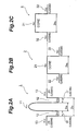
- Fig. 1A is a longitudinal sectional view showing a connecting portion of different kinds of optical fibers in a preferred embodiment of optical transmission line 5 in accordance with the present invention
- Fig. 1B is a longitudinal sectional view showing a splice portion of a conventional optical transmission line 6 for comparison.
- Fusion-splice in the optical transmission line 5 of this embodiment are an optical fiber 1 which is a dispersion-compensating optical fiber having a negative chromatic dispersion at a wavelength of 1.55 ⁇ m; and an optical fiber 2 which is a single-mode optical fiber, having a zero-dispersion wavelength in a 1.3- ⁇ m wavelength band and a positive chromatic dispersion at a wavelength of 1.55 ⁇ m, for an optical transmission line.
- Figs. 2A and 2B show respective refractive index profiles of optical fibers 1 and 2.
- the optical fiber 1 is an optical fiber having a so-called double cladding, and comprises, successively from its center, a core region 11 having a maximum refractive index n 11 and an outside diameter 2a 1 , a first cladding region 12 having a refractive index n 12 and an outside diameter 2b 1 , and a second cladding 13 having a refractive index n 13 , in which the individual refractive indices are set to n 11 > n 13 > n 12 in terms of the relationship of magnitude.
- the optical fiber 1 is silica glass based
- the core region 11 is doped with a high concentration of GeO 2
- the first cladding region 12 is doped with F element.
- the second cladding region 13 is a substantially pure silica glass or doped with about 0.5 wt% to 1.0 wt% of Cl element.
- the relative refractive index difference ⁇ 11 of core region 11 with reference to the refractive index n 13 of second cladding region 13 is at least 1%.
- Fig. 3 is a graph showing relationships between concentrations of various dopants (GeO 2 , Cl element, and F element) and relative refractive index difference, from which it is seen that the dopant concentration of GeO 2 is at least 18 wt% for realizing the relative refractive index difference ⁇ 11 of core region 11 when the second cladding region 13 is pure silica glass.
- Fig. 4 is a graph showing the relationship between viscosity and temperature in each of pure silica (SiO 2 ) glass, silica glass doped with 2 wt% of Cl element, and silica glass doped with 2 wt% of F element.
- the viscosity of silica glass decreases when any of substantially all the other elements or oxides is added thereto. Also, its viscosity has a property of decreasing as the temperature rises regardless of whether dopants exist or not.
- FIG. 5 is a graph showing the relationship between dopant concentration and viscosity at 1500 °C for each of three dopants of GeO 2 , Cl, and F.
- the decrease in viscosity is the largest when doped with F element, and the smallest when doped with GeO 2 .
- the core region 11 is doped with a large amount of GeO 2 in this embodiment, however, its viscosity ⁇ 11 is lower than the viscosity ⁇ 12 of the first cladding region 12 doped with F element, whereas the viscosity ⁇ 13 of the second cladding region 13 doped with no additive or only a minute amount of Cl element is the highest.
- the optical fiber 2 comprises, successively from its center, a core region 21 having a maximum refractive index n 21 and an outside diameter 2a 2 , and a cladding region 22 having a refractive index n 22 , whereas the individual refractive indices are set so as to have the relationship of n 21 > n 22 .
- the optical fiber 2 is based on silica glass, whereas the core region 21 is substantially pure silica glass or doped with about 0.5 wt% to 1.0 wt% of Cl element.
- the cladding region 22 is doped with F element.
- the viscosity ⁇ 22 of cladding region 22 is lower than the viscosity ⁇ 21 of core region 21, and lower than the viscosity ⁇ 13 of second cladding region 13 of optical fiber 1 (see Fig. 4).
- the optical fiber 2 has a low transmission loss since the dopant concentration of core region 21 is low, and is excellent in hydrogen- and radiation-resistant characteristics since the cladding region 22 is doped with F element, whereby it is an optical fiber suitably used for undersea cables.
- one or both of them may be doped with Cl element, and refractive index levels in both regions may differ from each other.
- the average viscosity ⁇ i of optical fiber i as a whole can be represented by the following expression: where ⁇ ij is the viscosity of its j-th layer (1 ⁇ j ⁇ n) , S ij is the cross-sectional area thereof, and S i is the total cross-sectional area.
- the respective core regions 11, 21 of optical fibers 1 and 2 can be restrained from deforming near the fusion-splice portion. This is because of the fact that the core region 11 and first cladding region 12 having a lower viscosity in the optical fiber 1 are surrounded by the second cladding region having a higher viscosity, and their end face at the fusion-splice portion is in a state blocked by the core region 21 having a higher viscosity in the optical fiber 2, whereby each of them can be restrained from deforming.
- optical fibers 1 and 2 which are a dispersion-compensating optical fiber and a single-mode optical fiber, respectively, are connected so as to form an optical transmission line, it is possible to construct an optical transmission line whose average chromatic dispersion and splice loss are so small that it is suitably used in a wavelength division multiplexing transmission system.
- heat treatment is carried out for thermal diffusion of dopants after fusion splice.
- This heat treatment can further lower the splice loss.
- a preferred condition for this heat treatment comprises a heating range with a heating length of at least 1 mm but less than 10 mm centered at the fusion-splice portion, and a maximum heating temperature of at least 1300 °C but less than 1800 °C.
- the heating temperature is selected within a temperature range in which the optical fibers 1, 2 are not deformed while the dopants can thermally diffuse.
- the optical transmission line 6 of a conventional product shown in Fig. 1B uses an optical fiber 3 as a single-mode optical fiber.
- this optical fiber 3 comprises, successively from its center, a core region 31 having a maximum refractive index n 31 and an outside diameter 2a 3 , and a cladding region 32 having a refractive index n 32 , whereas the individual refractive indices have the relationship of n 31 > n 32 in terms of magnitude.
- the optical fiber 3 is based on silica glass
- the core region 31 is doped with GeO 2
- the cladding region 32 is substantially pure silica glass.
- respective viscosities ⁇ 31 , ⁇ 32 of the individual regions have the relationship of ⁇ 31 ⁇ ⁇ 32 .
- optical fibers 3 and the optical fiber 1 are fusion-spliced, these optical fibers deform at their butting portions since they have a low viscosity at their center regions and both of them are easy to deform, whereby the core regions 11, 31 and inner cladding region 12 at their connecting portion increase their diameters as shown in Fig. 1B.
- the optical transmission line 5 of this embodiment has a structure for restraining the first optical fiber 1 having a smaller mode field diameter from deforming at the connecting end face upon fusion splice, so that the occurrence of fluctuation in mode field diameter can be suppressed, whereby splice loss can be prevented from increasing.
- the refractive index profile of first optical fiber 1 is not restricted thereto. More in general, preferable as the first optical fiber 1 is one having at least two cladding region layers, in which the outermost cladding region layer has a viscosity higher than that of the core region. Because of such a configuration, the cladding region does not deform upon fusion splice in the optical fiber 1, whereby the core region is restrained from deforming upon heating.
- the refractive index profile of second optical fiber 2 is not restricted thereto. More in general, preferable as the second optical fiber 2 is one having at least one cladding region layer, in which the outermost cladding region layer has a viscosity lower than that of the core region. Further preferable as the second optical fiber 2 is one in which the outermost cladding region layer has a viscosity lower than that of the cladding region of first optical fiber 1. Because of such a configuration, no structural changes occur in the core region of the optical fiber 2 even when the cladding softens upon fusion splice.
- the core region 21 of the optical fiber 2 having a larger mode field diameter has an outside diameter larger than that of the first cladding region 12 of the optical fiber 1 having a smaller mode field diameter. Because of such a configuration, the core region 11 and first cladding region 12 heavily influential to structural parameters of the optical fiber 1 are in a state as if lidded with the core region 21 of optical fiber 2, so as to be surrounded with glass having a high viscosity, whereby their forms can be maintained. Since the forms of core region 11 and first cladding region 12 are maintained in the optical fiber 1, the splice loss becomes lower.
- the core region 21 of second optical fiber has an average viscosity higher than that of the core region 11 and first cladding region 12 in the first optical fiber.
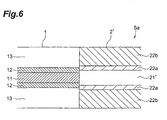
- Fig. 6 is a view showing a second embodiment of the optical transmission line in accordance with the present invention.
- the optical transmission line 5a of this embodiment differs from the optical transmission line 5 of the first embodiment in that its second optical fiber 2' has a double cladding structure.
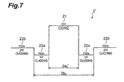
- Fig. 7 is a view for explaining the refractive index profile of the second optical fiber 2'. As shown in Figs.
- the second optical fiber 2' comprises, successively from its center, a core region 21 having a refractive index n 21 and an outside diameter 2a 2 ', a first cladding region 22a having a refractive index n 22a and an outside diameter 2b 2 , and a second cladding region 22b having a refractive index n 22b , whereas the individual refractive indices are set so as to have the relationship of n 21 > n 22b > n 22a .
- the optical fiber 2 is based on silica glass
- the core region 21 is substantially pure silica glass or doped with about 0.5 wt% to 1.0 wt% of Cl element.
- Each of the two cladding regions 22a, 22b is doped with F element, whereas the first cladding region 22a has a dopant concentration higher than that in the second cladding region 22b.
- each of the viscosities ⁇ 22a , ⁇ 22b of cladding region 22 is smaller than the viscosity ⁇ 21 of core region 21, and is smaller than the viscosity ⁇ 13 of second cladding 13 of first optical fiber 1 (see Fig. 4). Effects similar to those of the first embodiment can be achieved in this case as well.
- Tables 1 to 4 shown in the following are charts summarizing the optical fiber structures of individual samples (identified by case numbers), indicating 13 kinds of samples.
- cases 1 to 3 are structural examples of conventional products, i.e., comparative examples, whereas cases 4 to 13 are examples of the optical transmission line in accordance with the present invention.
- Core outside diameter ( ⁇ m) 1st cladding outside diameter ( ⁇ m) 2nd cladding outside diameter ( ⁇ m) 1 4.0 8.0 122 2 3.9 7.0 120 3 4.2 8.0 125 4 5 6 7 4.3 9.0 128 8 4.2 8.0 126 9 4.1 7.0 124 10 4.675 8.5 126 11 5.225 9.5 128 12 5.775 10.5 130 13 4.0 8.0 123 Dopant Concentration and Refractive Index Characteristic of First Optical Fiber Case No. Core dopant conc. (wt%) ⁇ n1 (%) 1st cladding dopant conc. (wt%) ⁇ n2 (%) 2nd cladding dopant conc.
- the first optical fiber with a smaller mode field diameter (MFD) in each case has the refractive index and structure shown in Fig. 2A, in which the core region is silica glass doped with GeO 2 , whereas the first cladding region is silica glass doped with F element.
- the second cladding region is substantially pure silica glass in cases 1 to 6, and silica glass doped with Cl element in cases 7 to 13.
- the outside diameter of first cladding region is within the range of 7 ⁇ m to 9 ⁇ m in cases 1 to 10 and 13, and exceeds 9 ⁇ m and thus is large in cases 11 and 12.
- each relative refractive index difference is based on the relative refractive index difference of pure silica glass.
- Second Optical Fiber Case No. Structure Core outside diameter ( ⁇ m) Core dopant 1 3 7.5 GeO 2 2 3 6.0 4 2 11.0 none 5 7.0 6 9.0 Cl 7 11.0 8 12.0 9 9.0 10 9.5 11 8.5 12 7.5 13 2' 12.0 Dopant Concentration and Refractive Index Characteristic of Second Optical Fiber Case No. Core dopant conc. (wt%) ⁇ n1 (%) 1st cladding dopant conc. (wt%) ⁇ n2 (%) 2nd cladding dopant conc.
- the numbers listed in the column of structure in Table 3 indicate which structures of optical fibers shown in Figs. 1A, 1B, and 6 are used as the second optical fiber. Namely, employed in cases 1 to 3 are those having the refractive index profile shown in Fig. 2C, in which the core region is silica glass doped with GeO 2 , whereas the cladding region is substantially pure silica glass (in cases 1 and 2) or silica glass doped with F element (in case 3).
- employed in cases 1 to 3 are those having the refractive index profile shown in Fig. 2C, in which the core region is silica glass doped with GeO 2 , whereas the cladding region is substantially pure silica glass (in cases 1 and 2) or silica glass doped with F element (in case 3).
- Employed as the second optical fiber in cases 4 to 12 are those having the refractive index profile shown in Fig.
- the core region is substantially pure silica glass (in cases 4 and 5) or silica glass doped with Cl element (in cases 6 to 12), whereas the cladding region is silica glass doped with F element.
- the second optical fiber is one having the refractive index profile shown in Fig. 7, in which the core region is silica glass doped with Cl element, whereas the first and second cladding regions are made of silica glass doped with F element.
- the outside diameter of core region of second optical fiber is within the range of 6.0 to 12.0 ⁇ m in each case.
- the outside diameter of second optical fiber is 125 ⁇ m in each case, whereas the outside diameter of first cladding in the second optical fiber employed in case 13 is set to 50 ⁇ m.
- Table 5 shows the respective mode field diameters (MFD) of first and second optical fibers, respective total average viscosities ⁇ 1 , ⁇ 2 thereof, average viscosity ⁇ 1c of the core region and first cladding region of first optical fiber, viscosity ⁇ 2c of the core region of second optical fiber, and results of comparison of splice losses after fusion and after the above-mentioned predetermined heat treatment when these optical fibers are fusion-spliced together are compared with each other.
- a necessary condition in the optical transmission line in accordance with the present invention is that the optical fiber with a smaller MFD has an average viscosity higher than that of the optical fiber having a larger MFD; cases 4 to 13, which are examples, satisfy this condition of ⁇ 1 > ⁇ 2 .
- the splice loss after fusion splice was 1.0 dB or greater in cases 1 to 3 which are comparative examples, and was within the range of 0.35 to 0.8 dB in cases 4 to 13 which are examples. In each case, the splice loss after heat treatment was smaller than that after fusion splice.
- the splice loss after fusion splice was about 1.0 to 2.0 dB in the prior art, it was allowed to decrease to about 0.35 to 0.8 dB by use of the optical fiber connecting method in accordance with this embodiment. Also, while the splice loss after heat treatment was about 0.3 to 0.6 dB in the prior art, it was allowed to decrease to about 0.11 to 0.3 dB by use of the optical fiber connecting method in accordance with this embodiment.
- cases 4, 6 to 10, and 13 in which the core of second optical fiber has an outside diameter larger than the outside diameter of first cladding yielded a splice loss of 0.3 dB or less which was small.
- the splice loss was 0.15 dB or less and was particularly small.
- Fig. 8 is a graph plotting the splice loss after heat treatment with respect to the ratio a 2 /b 1 of the outside diameter 2a 2 of core region in the second optical fiber to the outside diameter 2b 1 of first cladding in the first optical fiber.
- This graph indicates it preferable to set a 2 /b 1 to at least 1.05, i.e., set the outside diameter of core region in the second optical fiber to at least 1.05 times that of the first cladding region in the first optical fiber, since the splice loss after heat treatment can be suppressed to 0.2 dB or less thereby.
- the core and inner cladding region of first optical fiber which are easier to deform upon fusion splice, are covered with the harder core portion of second optical fiber, whereby their deforming is suppressed.
- the core diameter of second optical fiber be set to the inside diameter of outermost layer of first optical fiber or greater.
- Fig. 9 is a graph plotting the splice loss of each sample after heat treatment with respect to the ratio ⁇ 1c / ⁇ 2c of the average viscosity ⁇ 1c of the core and first cladding region of first optical fiber and the viscosity ⁇ 2c of core region of second optical fiber. It has been seen that, if ⁇ 1c / ⁇ 2c is 1/3 or less, i.e., ⁇ 2c is at least three times as much as ⁇ 1c , then the splice loss after heat treatment becomes 0.4 dB or less, whereby favorable characteristics can be exhibited.
- the present invention can be modified in various manners.
- the above-mentioned embodiments explain an optical transmission line in which a single-mode optical fiber (second optical fiber) having a zero-dispersion wavelength in a 1.3- ⁇ m wavelength band and a positive chromatic dispersion at a wavelength of 1.55 ⁇ m and a dispersion-compensating optical fiber (first optical fiber) having a negative chromatic dispersion at a wavelength of 1.55 ⁇ m are fusion-spliced, so as to compensate for chromatic dispersion, the present invention is not restricted thereto.
- the present invention is also suitably employed for restraining transmission characteristics from deteriorating due to four-wave mixing and chromatic dispersion in an optical transmission line in which positive and negative dispersion optical fibers respectively having positive and negative chromatic dispersions at a predetermined wavelength are alternately fusion-spliced.
- the present invention is suitably applicable to an optical transmission line including a portion in which optical fibers having structures and characteristics different from each other are fusion-spliced for suppressing chromatic dispersion and restraining transmission characteristics from deteriorating due to four-wave mixing and chromatic dispersion.
Landscapes
- Physics & Mathematics (AREA)
- General Physics & Mathematics (AREA)
- Optics & Photonics (AREA)
- Chemical & Material Sciences (AREA)
- Dispersion Chemistry (AREA)
- Engineering & Computer Science (AREA)
- Plasma & Fusion (AREA)
- Mechanical Coupling Of Light Guides (AREA)
Abstract
An optical transmission line including a portion formed by fusion-splicing optical fibers having structures different from each other; wherein, in the optical fibers having structures different from each other, a first optical fiber 1 has a mode field diameter smaller than that of a second optical fiber 2 fusion-spliced thereto; and wherein the first optical fiber 1 has an average viscosity from a center to an outermost layer greater than that of the second optical fiber from a center to an outermost layer. <IMAGE>
Description
The present invention relates to an optical
transmission line composed of fusion-splicing optical fibers
which have different structures each other; and, in
particular, to an optical transmission line including a
portion in which optical fibers having mode field diameters
different from each other are fusion-spliced.
Optical fibers are connected together by fusion splice,
which enables a permanent connection, in order to restrain
the splice loss at their splice portion from fluctuating.
However, the splice loss at the fusion-splice portion is
greater when optical fibers having structures different from
each other are fusion-spliced together than when optical
fibers having the same structure are fusion-spliced together.
For example, there is a case where a
dispersion-compensating optical fiber having a negative
chromatic dispersion at a wavelength of 1.55 µm is
fusion-spliced to a standard single-mode optical fiber having
a zero-dispersion wavelength in a 1.3-µm wavelength band
and a positive chromatic dispersion at a wavelength of 1.55
µm, so as to carry out dispersion compensation. The
single-mode optical fiber and dispersion-compensating
optical fiber greatly differ from each other in terms of
their fiber structures. Therefore, the splice loss at their
fusion-splice portion is about 1.0 to 2.0 dB, which is large.
Constructing an optical transmission line by
alternately fusion-splice positive and negative dispersion
optical fibers respectively having positive and negative
chromatic dispersions at a predetermined wavelength, for
example, has also been under consideration. Constructing
an optical transmission line as such yields a predetermined
value of chromatic dispersion or higher at each point on
the optical transmission line, so as to restrain transmission
characteristics from deteriorating due to four-wave mixing,
and lowers the average chromatic dispersion of the optical
transmission line as a whole, so as to restrain transmission
characteristics from deteriorating due to the chromatic
dispersion. In this case, for example, the positive
dispersion optical fiber has a step-index type refractive
index profile with a core diameter of 8 µm and a refractive
index difference of 0.35%, whereas the negative dispersion
optical fiber has a W type refractive index profile, whereby
their fiber structures greatly differ from each other.
Therefore, the splice loss at their fusion-splice portion
is about 0.8 to 1.5 dB, which is large.
Optical fiber connecting methods for eliminating such
problems are disclosed in Japanese Patent Application
Laid-Open No. HEI 3-130705 and Japanese Patent Application
Laid-Open No. SHO 57-24906. In the optical fiber connecting
method disclosed in Japanese Patent Application Laid-Open
No. HEI 3-130705, a first optical fiber having a larger core
diameter and a smaller relative refractive index difference
and a second optical fiber having a smaller core diameter
and a greater relative refractive index difference are
fusion-spliced together, and thus fusion-splice portion is
heat-treated at a predetermined temperature thereafter. In
the optical fiber connecting method disclosed in Japanese
Patent Application Laid-Open No. SHO 57-24906, on the other
hand, the first optical fiber whose core region has a higher
refractive index is heat-treated more strongly than the
second optical fiber after fusion splice. Both of the methods
intend to diffuse dopants in any of the first and second
optical fibers upon the heat treatment, so as to lower the
difference in their core diameters, thus making it possible
to decrease the splice loss at the fusion-splice portion.
Using these conventional optical fiber connecting
method is supposed to lower the splice loss at the
fusion-splice portion between the above-mentioned
single-mode optical fiber and dispersion-compensating
optical fiber to about 0.3 to 0.6 dB. It is also supposed
that the splice loss at the fusion-splice portion between
the above-mentioned positive and negative dispersion optical
fibers can be lowered to about 0.3 dB.
However, the splice loss at the fusion-splice portion
has not yet been considered small enough although it is
somewhat reduced by the conventional techniques disclosed
in the above-mentioned two publications.
The inventors of the present invention observed the
glass state near the fusion-splice portion in fusion-spliced
two optical fibers in detail. As a result of the observation,
it has been seen that, when a standard single-mode optical
fiber and a dispersion-compensating optical fiber are
fusion-spliced, the core region in the
dispersion-compensating optical fiber deforms as the
mode-field diameter is smaller.
Based on the inventors' findings mentioned above, for
eliminating the aforesaid problems, it is an object of the
present invention to provide an optical transmission line
constituted by optical fibers having structures different
from each other in which the connection loss at their
fusion-splice portion is further lowered.
The optical transmission line in accordance with the
present invention is an optical transmission line including
a portion formed by fusion-splicing optical fibers having
structures different from each other; wherein, in the optical
fibers having structures different from each other, a first
optical fiber has a mode field diameter smaller than a mode
field diameter of a second optical fiber fusion-spliced
thereto; and wherein the average viscosity from the center
to the outermost layer in the first optical fiber is greater
than the average viscosity from the center to the outermost
layer in the second optical fiber.
When the average viscosities in the first and second
optical fibers are set as such, the deformation of the core
region of the first optical fiber having a smaller mode field
diameter becomes smaller upon fusion splice, whereby the
splice loss can be restrained from increasing due to changes
in fiber structures.
Preferably, after the first and second optical fibers
are fusion-spliced, the optical transmission line is
heat-treated at the highest heating temperature of at least
1300 °C but not exceeding 1800 °C within a range having a
length of at least 1 mm but less than 10 mm centered at the
fusion-splice portion. In this case, the splice loss can
further be reduced.
The first optical fiber may be one having at least two
cladding region layers surrounding a core region, and the
average viscosity of the outermost cladding region layer
greater than that of the core region. In this case, the
cladding region does not deform upon fusion splice in the
first optical fiber, so that the core region is restrained
from deforming upon heating, whereby the splice loss can
be kept from increasing. Preferably, the first optical fiber
has a core region doped with GeO2 at a dopant concentration
of at least 18 wt%, a first cladding region doped with F
element, and an outermost cladding region layer doped with
Cl element.
Preferably, the second optical fiber has at least one
cladding region layer surrounding a core region, and the
average viscosity of the outermost cladding region layer
lower than any of the average viscosity of the core region
and that of the outermost cladding region layer in the first
optical fiber. In this case, no large structural changes
occur in the core region in the second optical fiber even
when its cladding softens upon fusion splice. Preferably,
the second optical fiber has a core region doped with Cl
element and a cladding region doped with F element.
Alternatively, the second optical fiber may have two cladding
region layers, the outer cladding region being doped with
F element by an amount smaller than that in the inner cladding
region.
Preferably, the core region of the second optical fiber
has an outside diameter greater than the inside diameter
of the outermost cladding region layer in the first optical
fiber. In this case, the core region and first cladding
region in the first optical fiber greatly influencing
structural parameters thereof appear as if lidded with the
core region of the second optical fiber, thus being surrounded
with glass having a high viscosity, whereby their forms are
easier to maintain.
Preferably, a part of the cladding region in the second
optical fiber is doped with F element, whereas an outermost
layer region thereof has an inside diameter of at least 1.05
times that of an outermost layer region in the first optical
fiber.
A part of the cladding region of the second optical
fiber may be doped with F element, the average viscosity
of regions inside an outermost cladding region layer is
greater than three times that of a region inside the outermost
cladding region layer of the first optical fiber. Such
setting can suppress the deformation of the region inside
the outermost cladding region layer in the first optical
fiber, whereby favorable connection characteristics can be
obtained.
The first and second optical fibers may have unlike
sign chromatic dispersions each other. Though the first and
second optical fibers have mode field diameters greatly
different from each other in general, the splice loss after
fusion splice or after heat treatment can be made smaller
in this case than in the conventional cases.
In the following, embodiments of the present invention
will be explained in detail with reference to the accompanying
drawings. To facilitate the comprehension of the
explanation, the same reference numerals denote the same
parts, where possible, throughout the drawings, and a
repeated explanation will be omitted.
Fig. 1A is a longitudinal sectional view showing a
connecting portion of different kinds of optical fibers in
a preferred embodiment of optical transmission line 5 in
accordance with the present invention, whereas Fig. 1B is
a longitudinal sectional view showing a splice portion of
a conventional optical transmission line 6 for comparison.
Fusion-splice in the optical transmission line 5 of
this embodiment are an optical fiber 1 which is a
dispersion-compensating optical fiber having a negative
chromatic dispersion at a wavelength of 1.55 µm; and an optical
fiber 2 which is a single-mode optical fiber, having a
zero-dispersion wavelength in a 1.3-µm wavelength band and
a positive chromatic dispersion at a wavelength of 1.55 µm,
for an optical transmission line. Figs. 2A and 2B show
respective refractive index profiles of optical fibers 1
and 2.
As shown in Figs. 1A and 2A, the optical fiber 1 is
an optical fiber having a so-called double cladding, and
comprises, successively from its center, a core region 11
having a maximum refractive index n11 and an outside diameter
2a1, a first cladding region 12 having a refractive index
n12 and an outside diameter 2b1, and a second cladding 13
having a refractive index n13, in which the individual
refractive indices are set to n11 > n13 > n12 in terms of the
relationship of magnitude. While the optical fiber 1 is
silica glass based, the core region 11 is doped with a high
concentration of GeO2, and the first cladding region 12 is
doped with F element. The second cladding region 13 is a
substantially pure silica glass or doped with about 0.5 wt%
to 1.0 wt% of Cl element. Preferably, the relative refractive
index difference Δ11 of core region 11 with reference to the
refractive index n13 of second cladding region 13 is at least
1%. Fig. 3 is a graph showing relationships between
concentrations of various dopants (GeO2, Cl element, and F
element) and relative refractive index difference, from which
it is seen that the dopant concentration of GeO2 is at least
18 wt% for realizing the relative refractive index difference
Δ11 of core region 11 when the second cladding region 13 is
pure silica glass.
When such setting is made, respective viscosities η11,
η12, η13 of the individual regions 11 to 13 within the optical
fiber 1 satisfy the relationship of η11 < η12 < η13. Fig. 4
is a graph showing the relationship between viscosity and
temperature in each of pure silica (SiO2) glass, silica glass
doped with 2 wt% of Cl element, and silica glass doped with
2 wt% of F element. In general, as can be seen from this
graph, the viscosity of silica glass decreases when any of
substantially all the other elements or oxides is added
thereto. Also, its viscosity has a property of decreasing
as the temperature rises regardless of whether dopants exist
or not. Fig. 5 is a graph showing the relationship between
dopant concentration and viscosity at 1500 °C for each of
three dopants of GeO2, Cl, and F. At the same dopant amount
(wt%), the decrease in viscosity is the largest when doped
with F element, and the smallest when doped with GeO2. Since
the core region 11 is doped with a large amount of GeO2 in
this embodiment, however, its viscosity η11 is lower than
the viscosity η12 of the first cladding region 12 doped with
F element, whereas the viscosity η13 of the second cladding
region 13 doped with no additive or only a minute amount
of Cl element is the highest.
On the other hand, as shown in Figs. 1A and 2B, the
optical fiber 2 comprises, successively from its center,
a core region 21 having a maximum refractive index n21 and
an outside diameter 2a2, and a cladding region 22 having a
refractive index n22, whereas the individual refractive
indices are set so as to have the relationship of n21 > n22.
The optical fiber 2 is based on silica glass, whereas the
core region 21 is substantially pure silica glass or doped
with about 0.5 wt% to 1.0 wt% of Cl element. The cladding
region 22 is doped with F element. As a result, the viscosity
η22 of cladding region 22 is lower than the viscosity η21 of
core region 21, and lower than the viscosity η13 of second
cladding region 13 of optical fiber 1 (see Fig. 4). The
optical fiber 2 has a low transmission loss since the dopant
concentration of core region 21 is low, and is excellent
in hydrogen- and radiation-resistant characteristics since
the cladding region 22 is doped with F element, whereby it
is an optical fiber suitably used for undersea cables.
Exemplified here is a case where each of the second
cladding region 13 of optical fiber 1 and the core region
21 of optical fiber 2 is pure silica glass, and both regions
have the same refractive index level (i.e., n13 = n21 holds) .
Of course, one or both of them may be doped with Cl element,
and refractive index levels in both regions may differ from
each other.
Letting the respective average viscosities of optical
fibers 1, 2 be η1, η2, the relationship of η1 > η2 holds. Here,
assuming that the optical fiber is composed of n layers,
the average viscosity ηi of optical fiber i as a whole can
be represented by the following expression:
 where ηij is the viscosity of its j-th layer (1 ≤ j ≤ n) , Sij
is the cross-sectional area thereof, and Si is the total
cross-sectional area.
where ηij is the viscosity of its j-th layer (1 ≤ j ≤ n) , Sij
is the cross-sectional area thereof, and Si is the total
cross-sectional area.
When thus set optical fibers 1 and 2 are fusion-spliced,
the respective core regions 11, 21 of optical fibers 1 and
2 can be restrained from deforming near the fusion-splice
portion. This is because of the fact that the core region
11 and first cladding region 12 having a lower viscosity
in the optical fiber 1 are surrounded by the second cladding
region having a higher viscosity, and their end face at the
fusion-splice portion is in a state blocked by the core region
21 having a higher viscosity in the optical fiber 2, whereby
each of them can be restrained from deforming.
When thus set optical fibers 1 and 2, which are a
dispersion-compensating optical fiber and a single-mode
optical fiber, respectively, are connected so as to form
an optical transmission line, it is possible to construct
an optical transmission line whose average chromatic
dispersion and splice loss are so small that it is suitably
used in a wavelength division multiplexing transmission
system.
Preferably, heat treatment is carried out for thermal
diffusion of dopants after fusion splice. This heat
treatment can further lower the splice loss. A preferred
condition for this heat treatment comprises a heating range
with a heating length of at least 1 mm but less than 10 mm
centered at the fusion-splice portion, and a maximum heating
temperature of at least 1300 °C but less than 1800 °C. The
heating temperature is selected within a temperature range
in which the optical fibers 1, 2 are not deformed while the
dopants can thermally diffuse.
The optical transmission line 6 of a conventional
product shown in Fig. 1B, by contrast, uses an optical fiber
3 as a single-mode optical fiber. As indicated by the
refractive index profile shown in Fig. 2C, this optical fiber
3 comprises, successively from its center, a core region
31 having a maximum refractive index n31 and an outside diameter
2a3, and a cladding region 32 having a refractive index n32,
whereas the individual refractive indices have the
relationship of n31 > n32 in terms of magnitude. While the
optical fiber 3 is based on silica glass, the core region
31 is doped with GeO2, and the cladding region 32 is
substantially pure silica glass. As a result, respective
viscosities η31, η32 of the individual regions have the
relationship of η31 < η32.
When such an optical fibers 3 and the optical fiber
1 are fusion-spliced, these optical fibers deform at their
butting portions since they have a low viscosity at their
center regions and both of them are easy to deform, whereby
the core regions 11, 31 and inner cladding region 12 at their
connecting portion increase their diameters as shown in Fig.
1B.
In the optical fiber 1 having a smaller mode field
diameter, in particular, even aminute change in the structure
of core region alters the mode field diameter greatly. The
splice loss is supposed to have increased in the conventional
product due to such a reason. By contrast, the optical
transmission line 5 of this embodiment has a structure for
restraining the first optical fiber 1 having a smaller mode
field diameter from deforming at the connecting end face
upon fusion splice, so that the occurrence of fluctuation
in mode field diameter can be suppressed, whereby splice
loss can be prevented from increasing.
Though one having the refractive index profile shown
in Fig. 2A is assumed as the first optical fiber 1 having
a smaller mode field diameter in this embodiment, the
refractive index profile of first optical fiber 1 is not
restricted thereto. More in general, preferable as the first
optical fiber 1 is one having at least two cladding region
layers, in which the outermost cladding region layer has
a viscosity higher than that of the core region. Because
of such a configuration, the cladding region does not deform
upon fusion splice in the optical fiber 1, whereby the core
region is restrained from deforming upon heating.
Though one having the refractive index profile shown
in Fig. 2B is assumed as the second optical fiber 2 having
a larger mode field diameter in this embodiment, the
refractive index profile of second optical fiber 2 is not
restricted thereto. More in general, preferable as the
second optical fiber 2 is one having at least one cladding
region layer, in which the outermost cladding region layer
has a viscosity lower than that of the core region. Further
preferable as the second optical fiber 2 is one in which
the outermost cladding region layer has a viscosity lower
than that of the cladding region of first optical fiber 1.
Because of such a configuration, no structural changes occur
in the core region of the optical fiber 2 even when the cladding
softens upon fusion splice.
Preferably, the core region 21 of the optical fiber
2 having a larger mode field diameter has an outside diameter
larger than that of the first cladding region 12 of the optical
fiber 1 having a smaller mode field diameter. Because of
such a configuration, the core region 11 and first cladding
region 12 heavily influential to structural parameters of
the optical fiber 1 are in a state as if lidded with the
core region 21 of optical fiber 2, so as to be surrounded
with glass having a high viscosity, whereby their forms can
be maintained. Since the forms of core region 11 and first
cladding region 12 are maintained in the optical fiber 1,
the splice loss becomes lower.
Preferably, in this case, the core region 21 of second
optical fiber has an average viscosity higher than that of
the core region 11 and first cladding region 12 in the first
optical fiber. Here, the average viscosity ηave of the core
region 11 and first cladding region 12 in the optical fiber
1 can be represented by the following expression:
ηave = ηa ×Sa +η b ×Sb Sa +Sb
where ηa is the viscosity of the core portion, ηb is the
viscosity of the cladding region, and Sa and Sb are their
respective cross-sectional areas.
Such setting reliably yields the effect of lidding with
the core region 21 of second optical fiber.
Fig. 6 is a view showing a second embodiment of the
optical transmission line in accordance with the present
invention. The optical transmission line 5a of this
embodiment differs from the optical transmission line 5 of
the first embodiment in that its second optical fiber 2'
has a double cladding structure. Fig. 7 is a view for
explaining the refractive index profile of the second optical
fiber 2'. As shown in Figs. 6 and 7, the second optical fiber
2' comprises, successively from its center, a core region
21 having a refractive index n21 and an outside diameter 2a2',
a first cladding region 22a having a refractive index n22a
and an outside diameter 2b2, and a second cladding region
22b having a refractive index n22b, whereas the individual
refractive indices are set so as to have the relationship
of n21 > n22b > n22a. While the optical fiber 2 is based on
silica glass, the core region 21 is substantially pure silica
glass or doped with about 0.5 wt% to 1.0 wt% of Cl element.
Each of the two cladding regions 22a, 22b is doped with F
element, whereas the first cladding region 22a has a dopant
concentration higher than that in the second cladding region
22b. As a result, each of the viscosities η22a, η22b of cladding
region 22 is smaller than the viscosity η21 of core region
21, and is smaller than the viscosity η13 of second cladding
13 of first optical fiber 1 (see Fig. 4). Effects similar
to those of the first embodiment can be achieved in this
case as well.
In order to verify the effects of splice loss reduction
in the optical transmission line in accordance with the
present invention, the inventors prepared several kinds of
samples and carried out experiments for comparing them with
conventional optical transmission line samples. The
results of experiments will now be explained.
Tables 1 to 4 shown in the following are charts
summarizing the optical fiber structures of individual
samples (identified by case numbers), indicating 13 kinds
of samples. Here, cases 1 to 3 are structural examples of
conventional products, i.e., comparative examples, whereas
cases 4 to 13 are examples of the optical transmission line
in accordance with the present invention.
| Structure of First Optical Fiber | |||
| Case No. | Core outside diameter (µm) | 1st cladding outside diameter (µm) | 2nd cladding outside diameter (µm) |
| 1 | 4.0 | 8.0 | 122 |
| 2 | 3.9 | 7.0 | 120 |
| 3 | 4.2 | 8.0 | 125 |
| 4 | |||
| 5 | |||
| 6 | |||
| 7 | 4.3 | 9.0 | 128 |
| 8 | 4.2 | 8.0 | 126 |
| 9 | 4.1 | 7.0 | 124 |
| 10 | 4.675 | 8.5 | 126 |
| 11 | 5.225 | 9.5 | 128 |
| 12 | 5.775 | 10.5 | 130 |
| 13 | 4.0 | 8.0 | 123 |
| Dopant Concentration and Refractive Index Characteristic of First Optical Fiber | ||||||
| Case No. | Core dopant conc. (wt%) | Δn1 (%) | 1st cladding dopant conc. (wt%) | Δn2 (%) | 2nd cladding dopant conc. (wt%) | Δn3 (%) |
| 1 | 30.94 | 1.70 | 1.365 | -0.35 | 0.00 | 0.00 |
| 2 | 27.30 | 1.50 | ||||
| 3 | 26.39 | 1.45 | 1.56 | -0.40 | 0.20 | 0.022 |
| 4 | ||||||
| 5 | ||||||
| 6 | ||||||
| 7 | 25.48 | 1.40 | 1.17 | -0.30 | 0.455 | 0.05 |
| 8 | ||||||
| 9 | ||||||
| 10 | 27.30 | 1.50 | 1.56 | -0.40 | ||
| 11 | ||||||
| 12 | ||||||
| 13 |
As can be seen from Tables 1 and 2, the first optical
fiber with a smaller mode field diameter (MFD) in each case
has the refractive index and structure shown in Fig. 2A,
in which the core region is silica glass doped with GeO2,
whereas the first cladding region is silica glass doped with
F element. The second cladding region is substantially pure
silica glass in cases 1 to 6, and silica glass doped with
Cl element in cases 7 to 13. The outside diameter of first
cladding region is within the range of 7 µm to 9 µm in cases
1 to 10 and 13, and exceeds 9 µm and thus is large in cases
11 and 12. In Table 2, each relative refractive index
difference is based on the relative refractive index
difference of pure silica glass.
| Structure of Second Optical Fiber | |||
| Case No. | Structure | Core outside diameter (µm) | |
| 1 | 3 | 7.5 | |
| 2 | |||
| 3 | 6.0 | ||
| 4 | 2 | 11.0 | |
| 5 | 7.0 | ||
| 6 | 9.0 | Cl | |
| 7 | 11.0 | ||
| 8 | 12.0 | ||
| 9 | 9.0 | ||
| 10 | 9.5 | ||
| 11 | 8.5 | ||
| 12 | 7.5 | ||
| 13 | 2' | 12.0 |
| Dopant Concentration and Refractive Index Characteristic of Second Optical Fiber | ||||||
| Case No. | Core dopant conc. (wt%) | Δn1 (%) | 1st cladding dopant conc. (wt%) | Δn2 (%) | 2nd cladding dopant conc. (wt%) | Δn3 (%) |
| 1 | 6.188 | 0.34 | 0.0 | 0.0 | - | - |
| 2 | ||||||
| 3 | 10.01 | 0.55 | 0.195 | -0.05 | ||
| 4 | 0.0 | 0.0 | 1.248 | -0.32 | ||
| 5 | ||||||
| 6 | 0.455 | 0.05 | 0.975 | -0.25 | ||
| 7 | ||||||
| 8 | ||||||
| 9 | 0.637 | 0.07 | 1.092 | -0.28 | ||
| 10 | ||||||
| 11 | ||||||
| 12 | ||||||
| 13 | 0.78 | -0.2 |
The numbers listed in the column of structure in Table
3 indicate which structures of optical fibers shown in Figs.
1A, 1B, and 6 are used as the second optical fiber. Namely,
employed in cases 1 to 3 are those having the refractive
index profile shown in Fig. 2C, in which the core region
is silica glass doped with GeO2, whereas the cladding region
is substantially pure silica glass (in cases 1 and 2) or
silica glass doped with F element (in case 3). Employed as
the second optical fiber in cases 4 to 12 are those having
the refractive index profile shown in Fig. 2B, in which the
core region is substantially pure silica glass (in cases
4 and 5) or silica glass doped with Cl element (in cases
6 to 12), whereas the cladding region is silica glass doped
with F element. In case 13, the second optical fiber is one
having the refractive index profile shown in Fig. 7, in which
the core region is silica glass doped with Cl element, whereas
the first and second cladding regions are made of silica
glass doped with F element. The outside diameter of core
region of second optical fiber is within the range of 6.0
to 12.0 µm in each case. The outside diameter of second
optical fiber is 125 µm in each case, whereas the outside
diameter of first cladding in the second optical fiber
employed in case 13 is set to 50 µm.
Table 5 shows the respective mode field diameters (MFD)
of first and second optical fibers, respective total average
viscosities η1, η2 thereof, average viscosity η1c of the core
region and first cladding region of first optical fiber,
viscosity η2c of the core region of second optical fiber,
and results of comparison of splice losses after fusion and
after the above-mentioned predetermined heat treatment when
these optical fibers are fusion-spliced together are compared
with each other.
| Comparison of Characteristics of First and Second Optical Fibers and Comparison of Splice Loss | ||||||||
| 1st optical fiber | 2nd optical fiber | splice loss | ||||||
| Case | MFD | η1 | η1c | MFD | η2 | η2c | after fusion splice | after heating |
| No. | (µm) | (×108P) | (µm) | (×108P) | (dB) | |||
| 1 | 4.5 | 30 | 2.08 | 10.3 | 30 | 1.545 | 1.5 | 1.0 |
| 2 | 5.0 | 1.91 | 1.6 | 0.9 | ||||
| 3 | 5.1 | 17 | 1.52 | 8.2 | 18 | 0.3178 | 1.0 | 0.6 |
| 4 | 11.5 | 1.3 | 30.0 | 0.5 | 0.2 | |||
| 5 | 10.5 | 1.1 | 30.0 | 0.8 | 0.3 | |||
| 6 | 11.1 | 2.2 | 10.36 | 0.6 | 0.2 | |||
| 7 | 4.9 | 8.8 | 2.84 | 11.7 | 2.3 | 0.4 | 0.15 | |
| 8 | 5.2 | 2.67 | 12.1 | 0.35 | 0.11 | |||
| 9 | 5.2 | 2.42 | 10.3 | 1.6 | 7.958 | 0.35 | 0.12 | |
| 10 | 5.0 | 2.57 | 10.5 | 0.4 | 0.15 | |||
| 11 | 4.8 | 10.2 | 0.45 | 0.3 | ||||
| 12 | 4.7 | 10.0 | 0.55 | 0.4 | ||||
| 13 | 4.9 | 1.57 | 12.0 | 3.4 | 0.70 | 0.2 |
A necessary condition in the optical transmission line
in accordance with the present invention is that the optical
fiber with a smaller MFD has an average viscosity higher
than that of the optical fiber having a larger MFD; cases
4 to 13, which are examples, satisfy this condition of η1
> η2. The splice loss after fusion splice was 1.0 dB or greater
in cases 1 to 3 which are comparative examples, and was within
the range of 0.35 to 0.8 dB in cases 4 to 13 which are examples.
In each case, the splice loss after heat treatment was smaller
than that after fusion splice. Though the splice loss after
heat treatment was still 0.6 dB or greater in cases 1 to
3 which are comparative examples, it was 0.4 dB or less in
cases 4 to 13 which are examples and within the range of
0.11 to 0.3 dB in examples excluding case 12.
As in the foregoing, while the splice loss after fusion
splice was about 1.0 to 2.0 dB in the prior art, it was allowed
to decrease to about 0.35 to 0.8 dB by use of the optical
fiber connecting method in accordance with this embodiment.
Also, while the splice loss after heat treatment was about
0.3 to 0.6 dB in the prior art, it was allowed to decrease
to about 0.11 to 0.3 dB by use of the optical fiber connecting
method in accordance with this embodiment.
In particular, among those in accordance with this
embodiment, cases 4, 6 to 10, and 13 in which the core of
second optical fiber has an outside diameter larger than
the outside diameter of first cladding yielded a splice loss
of 0.3 dB or less which was small. In cases 7 to 10 among
them, the splice loss was 0.15 dB or less and was particularly
small. Fig. 8 is a graph plotting the splice loss after heat
treatment with respect to the ratio a2/b1 of the outside
diameter 2a2 of core region in the second optical fiber to
the outside diameter 2b1 of first cladding in the first optical
fiber. This graph indicates it preferable to set a2/b1 to
at least 1.05, i.e., set the outside diameter of core region
in the second optical fiber to at least 1.05 times that of
the first cladding region in the first optical fiber, since
the splice loss after heat treatment can be suppressed to
0.2 dB or less thereby. This is because of the fact that,
in such setting, the core and inner cladding region of first
optical fiber, which are easier to deform upon fusion splice,
are covered with the harder core portion of second optical
fiber, whereby their deforming is suppressed. In the case
where the first optical fiber has a structure made of four
or more layers, it is preferred that the core diameter of
second optical fiber be set to the inside diameter of outermost
layer of first optical fiber or greater.
Fig. 9 is a graph plotting the splice loss of each sample
after heat treatment with respect to the ratio η1c/η2c of the
average viscosity η1c of the core and first cladding region
of first optical fiber and the viscosity η2c of core region
of second optical fiber. It has been seen that, if η1c/η2c
is 1/3 or less, i.e., η2c is at least three times as much
as η1c, then the splice loss after heat treatment becomes
0.4 dB or less, whereby favorable characteristics can be
exhibited.
Without being restricted to the above-mentioned
embodiments, the present invention can be modified in various
manners. Though the above-mentioned embodiments explain an
optical transmission line in which a single-mode optical
fiber (second optical fiber) having a zero-dispersion
wavelength in a 1.3-µm wavelength band and a positive
chromatic dispersion at a wavelength of 1.55 µm and a
dispersion-compensating optical fiber (first optical fiber)
having a negative chromatic dispersion at a wavelength of
1.55 µm are fusion-spliced, so as to compensate for chromatic
dispersion, the present invention is not restricted thereto.
For example, the present invention is also suitably employed
for restraining transmission characteristics from
deteriorating due to four-wave mixing and chromatic
dispersion in an optical transmission line in which positive
and negative dispersion optical fibers respectively having
positive and negative chromatic dispersions at a
predetermined wavelength are alternately fusion-spliced.
The present invention is suitably applicable to an
optical transmission line including a portion in which
optical fibers having structures and characteristics
different from each other are fusion-spliced for suppressing
chromatic dispersion and restraining transmission
characteristics from deteriorating due to four-wave mixing
and chromatic dispersion.
Claims (11)
- An optical transmission line including a portion formed by fusion-splicing optical fibers having structures different from each other;
wherein, in said optical fibers having structures different from each other, a first optical fiber has a mode field diameter smaller than a mode field diameter of a second optical fiber fusion-spliced thereto; and wherein the average viscosity from the center to the outermost layer in said first optical fiber is greater than the average viscosity from the center to the outermost layer in said second optical fiber. - An optical transmission line according to claim 1, wherein, after said first and second optical fibers are fusion-spliced, said optical transmission line is heat-treated at the highest heating temperature of at least 1300 °C but not exceeding 1800 °C within a range having a length of at least 1 mm but less than 10 mm centered at said fusion-splice portion.
- An optical transmission line according to claim 1, wherein said first optical fiber has at least two cladding region layers surrounding a core region, and the average viscosity of the outermost cladding region layer greater than the average viscosity of said core region.
- An optical transmission line according to claim 3, wherein said first optical fiber has a core region doped with GeO2 at a dopant concentration of at least 18 wt%, a first cladding region doped with F element, and an outermost cladding region layer doped with Cl element.
- An optical transmission line according to claim 1, wherein said second optical fiber has at least one cladding region layer surrounding a core region, and the average viscosity of the outermost cladding region layer lower than any of the average viscosity of said core region and the average viscosity of the outermost cladding region layer in said first optical fiber.
- An optical transmission line according to claim 1, wherein said second optical fiber has a core region doped with Cl element and a cladding region doped with F element.
- An optical transmission line according to claim 6, wherein said second optical fiber has two cladding region layers, the outer cladding region being doped with F element by an amount smaller than that in the inner cladding region.
- An optical transmission line according to claim 3, wherein said core region of said second optical fiber has an outside diameter greater than the inside diameter of said outermost cladding region layer in said first optical fiber.
- An optical transmission line according to claim 8, wherein a part of cladding region in said second optical fiber is doped with F element, said core region thereof has an outside diameter of at least 1.05 times the inside diameter of said outermost layer region in said first optical fiber.
- An optical transmission line according to claim 8, wherein a part of cladding region in said second optical fiber is doped with F element, said core region thereof has a viscosity greater than three times the average viscosity of a region inside said outermost cladding region layer in said first optical fiber.
- An optical transmission line according to claim 1, wherein said first and second optical fibers have unlike sign chromatic dispersions each other.
Applications Claiming Priority (3)
| Application Number | Priority Date | Filing Date | Title |
|---|---|---|---|
| JP31380399 | 1999-11-04 | ||
| JP31380399 | 1999-11-04 | ||
| PCT/JP2000/007747 WO2001033266A1 (en) | 1999-11-04 | 2000-11-02 | Optical transmission line |
Publications (2)
| Publication Number | Publication Date |
|---|---|
| EP1174741A1 true EP1174741A1 (en) | 2002-01-23 |
| EP1174741A4 EP1174741A4 (en) | 2005-11-09 |
Family
ID=18045716
Family Applications (1)
| Application Number | Title | Priority Date | Filing Date |
|---|---|---|---|
| EP00971766A Withdrawn EP1174741A4 (en) | 1999-11-04 | 2000-11-02 | OPTICAL TRANSMISSION LINE |
Country Status (4)
| Country | Link |
|---|---|
| US (1) | US6805497B1 (en) |
| EP (1) | EP1174741A4 (en) |
| AU (1) | AU754530B2 (en) |
| WO (1) | WO2001033266A1 (en) |
Cited By (5)
| Publication number | Priority date | Publication date | Assignee | Title |
|---|---|---|---|---|
| EP1219987A1 (en) * | 2000-12-28 | 2002-07-03 | Sumitomo Electric Industries, Ltd. | Optical fiber splicing method |
| US6690868B2 (en) | 2001-05-30 | 2004-02-10 | 3M Innovative Properties Company | Optical waveguide article including a fluorine-containing zone |
| US6742939B2 (en) | 2001-05-30 | 2004-06-01 | 3M Innovative Properties Company | Optical fiber fusion splice having a controlled mode field diameter expansion match |
| US6789960B2 (en) | 2001-07-06 | 2004-09-14 | Corning Incorporated | Method of connecting optical fibers, an optical fiber therefor, and an optical fiber span therefrom |
| GB2526590A (en) * | 2014-05-29 | 2015-12-02 | Fibercore Ltd | Optical fiber and method of producing an optical fiber |
Families Citing this family (5)
| Publication number | Priority date | Publication date | Assignee | Title |
|---|---|---|---|---|
| US7257301B2 (en) * | 2005-03-31 | 2007-08-14 | Baker Hughes Incorporated | Optical fiber |
| CN102243336B (en) * | 2011-07-25 | 2013-06-05 | 长飞光纤光缆有限公司 | Dispersion compensation fiber |
| JP6312760B2 (en) | 2016-08-30 | 2018-04-18 | 株式会社フジクラ | Optical fiber |
| CN109983379B (en) | 2016-11-25 | 2021-04-27 | 住友电气工业株式会社 | Optical fiber line and optical fiber line manufacturing method |
| JP6564418B2 (en) * | 2017-04-20 | 2019-08-21 | ファナック株式会社 | Optical power monitor device and laser device |
Family Cites Families (14)
| Publication number | Priority date | Publication date | Assignee | Title |
|---|---|---|---|---|
| JPS5724906A (en) | 1980-07-22 | 1982-02-09 | Nippon Telegr & Teleph Corp <Ntt> | Connecting method for optical fiber by melt-sticking |
| US5217516A (en) * | 1985-12-27 | 1993-06-08 | Sumitomo Electric Industries, Ltd. | Method of making optical glass article |
| JPH0196039A (en) * | 1987-10-07 | 1989-04-14 | Sumitomo Electric Ind Ltd | Production of optical fiber preform |
| GB8810286D0 (en) * | 1988-04-29 | 1988-06-02 | British Telecomm | Connecting optical waveguides |
| JP2618500B2 (en) * | 1989-10-17 | 1997-06-11 | 日本電信電話株式会社 | Optical fiber connection method |
| JP2584145B2 (en) * | 1991-04-17 | 1997-02-19 | 株式会社フジクラ | High dispersion optical fiber |
| JP3049697B2 (en) * | 1992-07-29 | 2000-06-05 | 住友電気工業株式会社 | Mode field diameter conversion fiber |
| JPH07261048A (en) * | 1994-03-23 | 1995-10-13 | Sumitomo Electric Ind Ltd | Dispersion compensating fiber |
| JPH08201642A (en) * | 1995-01-25 | 1996-08-09 | Fujitsu Ltd | Optical fiber connection method and device, and reinforcing structure |
| CA2170815C (en) * | 1995-03-10 | 2002-05-28 | Youichi Akasaka | Dispersion compensating optical fiber |
| JP3362329B2 (en) | 1995-06-26 | 2003-01-07 | 住友電気工業株式会社 | Optical fiber connecting member, manufacturing method and connecting method |
| CA2202586C (en) * | 1996-04-15 | 2003-05-06 | Masashi Onishi | Dispersion compensating fiber and optical transmission system including the same |
| SE511966C2 (en) * | 1997-06-09 | 1999-12-20 | Ericsson Telefon Ab L M | Method and apparatus for jointing the ends of two optical fibers of different type with each other |
| US6362249B2 (en) * | 1998-09-04 | 2002-03-26 | Dsm Desotech Inc. | Radiation-curable coating compositions, coated optical fiber, radiation-curable matrix forming material and ribbon assembly |
-
2000
- 2000-11-02 WO PCT/JP2000/007747 patent/WO2001033266A1/en not_active Ceased
- 2000-11-02 AU AU10555/01A patent/AU754530B2/en not_active Ceased
- 2000-11-02 US US09/869,698 patent/US6805497B1/en not_active Expired - Fee Related
- 2000-11-02 EP EP00971766A patent/EP1174741A4/en not_active Withdrawn
Cited By (7)
| Publication number | Priority date | Publication date | Assignee | Title |
|---|---|---|---|---|
| EP1219987A1 (en) * | 2000-12-28 | 2002-07-03 | Sumitomo Electric Industries, Ltd. | Optical fiber splicing method |
| US6729777B2 (en) | 2000-12-28 | 2004-05-04 | Sumitomo Electric Industries, Ltd. | Optical fiber splicing method and optical transmission line |
| US6690868B2 (en) | 2001-05-30 | 2004-02-10 | 3M Innovative Properties Company | Optical waveguide article including a fluorine-containing zone |
| US6742939B2 (en) | 2001-05-30 | 2004-06-01 | 3M Innovative Properties Company | Optical fiber fusion splice having a controlled mode field diameter expansion match |
| US6789960B2 (en) | 2001-07-06 | 2004-09-14 | Corning Incorporated | Method of connecting optical fibers, an optical fiber therefor, and an optical fiber span therefrom |
| GB2526590A (en) * | 2014-05-29 | 2015-12-02 | Fibercore Ltd | Optical fiber and method of producing an optical fiber |
| US10261242B2 (en) | 2014-05-29 | 2019-04-16 | Fibercore Limited | Optical fiber and method of producing an optical fiber |
Also Published As
| Publication number | Publication date |
|---|---|
| AU754530B2 (en) | 2002-11-21 |
| AU1055501A (en) | 2001-05-14 |
| EP1174741A4 (en) | 2005-11-09 |
| US6805497B1 (en) | 2004-10-19 |
| WO2001033266A1 (en) | 2001-05-10 |
Similar Documents
| Publication | Publication Date | Title |
|---|---|---|
| EP1740986B1 (en) | Low attenuation large effective area optical fiber | |
| EP0779524B1 (en) | Large effective area single mode optical waveguide | |
| EP2352046B1 (en) | Non-zero dispersion shifted optical fiber having a short cutoff wavelength | |
| US6062046A (en) | Method of making a single-mode optical fiber with multiple concentric core portions including the RIT process | |
| EP3280687B1 (en) | Low attenuation single mode optical fiber with stress relieving layer, its preform and a method of making it | |
| EP2588905B1 (en) | Optical fibre with a large effective area having a graded index germanium free core | |
| EP2713188B1 (en) | Single mode optical fibre | |
| EP2529261B1 (en) | Large effective area fiber with ge-free core | |
| EP0785448B1 (en) | Dispersion-shifted fiber | |
| EP2145219B1 (en) | Large effective area fiber | |
| EP2352047B1 (en) | Non-zero dispersion shifted optical fiber having a large effective area | |
| US8538219B2 (en) | Large effective area optical fiber with low bend loss | |
| EP1145057B1 (en) | Optical fiber | |
| EP2581770A2 (en) | Optical fiber and optical cable | |
| EP3521878A1 (en) | High sbs threshold optical fiber with aluminium dopant | |
| US6805497B1 (en) | Optical transmission line | |
| EP0856754A1 (en) | Single-mode optical fiber | |
| WO2011066063A1 (en) | Large effective area fiber | |
| US6563989B2 (en) | Optical fiber coupler and optical fiber for optical fiber coupler | |
| AU8583298A (en) | Dispersion managed optical waveguide fiber | |
| JP2951562B2 (en) | Connection structure and connection method of dispersion compensating optical fiber | |
| US6360046B1 (en) | Dispersion-shifted optical fiber | |
| US6729777B2 (en) | Optical fiber splicing method and optical transmission line | |
| EP4231065A1 (en) | Trench assisted multi-core optical fiber with reduced crosstalk | |
| KR20060110311A (en) | Dispersion Compensation Fiber for Intermediate Dispersion NSD |
Legal Events
| Date | Code | Title | Description |
|---|---|---|---|
| PUAI | Public reference made under article 153(3) epc to a published international application that has entered the european phase |
Free format text: ORIGINAL CODE: 0009012 |
|
| 17P | Request for examination filed |
Effective date: 20010731 |
|
| AK | Designated contracting states |
Kind code of ref document: A1 Designated state(s): AT BE CH CY DE DK ES FI FR GB GR IE IT LI LU MC NL PT SE TR |
|
| RBV | Designated contracting states (corrected) |
Designated state(s): DE FR GB IT |
|
| A4 | Supplementary search report drawn up and despatched |
Effective date: 20050922 |
|
| STAA | Information on the status of an ep patent application or granted ep patent |
Free format text: STATUS: THE APPLICATION IS DEEMED TO BE WITHDRAWN |
|
| 18D | Application deemed to be withdrawn |
Effective date: 20060216 |