EP1012435B1 - Plug connector for hollow profiles - Google Patents
Plug connector for hollow profiles Download PDFInfo
- Publication number
- EP1012435B1 EP1012435B1 EP98952589A EP98952589A EP1012435B1 EP 1012435 B1 EP1012435 B1 EP 1012435B1 EP 98952589 A EP98952589 A EP 98952589A EP 98952589 A EP98952589 A EP 98952589A EP 1012435 B1 EP1012435 B1 EP 1012435B1
- Authority
- EP
- European Patent Office
- Prior art keywords
- plug
- connector
- stops
- connector according
- connecting location
- Prior art date
- Legal status (The legal status is an assumption and is not a legal conclusion. Google has not performed a legal analysis and makes no representation as to the accuracy of the status listed.)
- Expired - Lifetime
Links
- 230000007704 transition Effects 0.000 claims abstract description 10
- 229910052751 metal Inorganic materials 0.000 claims abstract description 4
- 239000002184 metal Substances 0.000 claims abstract description 4
- 238000007789 sealing Methods 0.000 claims description 41
- 125000006850 spacer group Chemical group 0.000 claims description 9
- 239000011521 glass Substances 0.000 claims description 6
- 239000002984 plastic foam Substances 0.000 claims description 2
- 238000004026 adhesive bonding Methods 0.000 claims 1
- 238000009434 installation Methods 0.000 claims 1
- 230000000452 restraining effect Effects 0.000 claims 1
- 210000001331 nose Anatomy 0.000 description 8
- 230000000694 effects Effects 0.000 description 6
- 239000002274 desiccant Substances 0.000 description 4
- 229910000838 Al alloy Inorganic materials 0.000 description 2
- 229910000831 Steel Inorganic materials 0.000 description 2
- 239000000853 adhesive Substances 0.000 description 2
- 230000001070 adhesive effect Effects 0.000 description 2
- 238000005452 bending Methods 0.000 description 2
- 230000015572 biosynthetic process Effects 0.000 description 2
- 210000003746 feather Anatomy 0.000 description 2
- 239000008187 granular material Substances 0.000 description 2
- 210000001503 joint Anatomy 0.000 description 2
- 230000014759 maintenance of location Effects 0.000 description 2
- 239000010935 stainless steel Substances 0.000 description 2
- 229910001220 stainless steel Inorganic materials 0.000 description 2
- 239000010959 steel Substances 0.000 description 2
- 206010000496 acne Diseases 0.000 description 1
- 230000006978 adaptation Effects 0.000 description 1
- XAGFODPZIPBFFR-UHFFFAOYSA-N aluminium Chemical compound [Al] XAGFODPZIPBFFR-UHFFFAOYSA-N 0.000 description 1
- 230000002146 bilateral effect Effects 0.000 description 1
- 125000000484 butyl group Chemical group [H]C([*])([H])C([H])([H])C([H])([H])C([H])([H])[H] 0.000 description 1
- 239000002131 composite material Substances 0.000 description 1
- 150000001875 compounds Chemical class 0.000 description 1
- 230000006835 compression Effects 0.000 description 1
- 238000007906 compression Methods 0.000 description 1
- 238000010276 construction Methods 0.000 description 1
- 239000000428 dust Substances 0.000 description 1
- 239000013013 elastic material Substances 0.000 description 1
- 210000003128 head Anatomy 0.000 description 1
- 239000000463 material Substances 0.000 description 1
- 230000003287 optical effect Effects 0.000 description 1
- 239000004033 plastic Substances 0.000 description 1
- 230000000630 rising effect Effects 0.000 description 1
- 239000000565 sealant Substances 0.000 description 1
- 230000006641 stabilisation Effects 0.000 description 1
- 238000011105 stabilization Methods 0.000 description 1
- 239000006228 supernatant Substances 0.000 description 1
Images


Classifications
-
- E—FIXED CONSTRUCTIONS
- E06—DOORS, WINDOWS, SHUTTERS, OR ROLLER BLINDS IN GENERAL; LADDERS
- E06B—FIXED OR MOVABLE CLOSURES FOR OPENINGS IN BUILDINGS, VEHICLES, FENCES OR LIKE ENCLOSURES IN GENERAL, e.g. DOORS, WINDOWS, BLINDS, GATES
- E06B3/00—Window sashes, door leaves, or like elements for closing wall or like openings; Layout of fixed or moving closures, e.g. windows in wall or like openings; Features of rigidly-mounted outer frames relating to the mounting of wing frames
- E06B3/66—Units comprising two or more parallel glass or like panes permanently secured together
- E06B3/663—Elements for spacing panes
- E06B3/667—Connectors therefor
Definitions
- the invention relates to a connector for Hollow profiles, especially spacers from Insulating glass panes, with the features in the preamble of Main claim.
- Such a connector is from EP-A-0 330 906 known.
- the connector has a U-shaped Cross section with a central bar and two on it adjacent side bridges. At the transition between Mittelund Sidewalls are stops and bevels separated and spaced apart. The Stops act on both sides and distance the Hollow profiles forming a joint on the Junction through which a sealant enters from outside the hollow profiles can be injected.
- the In cross section, bevels have a triangular shape and are lower than that at their highest point adjacent stop.
- the ramp bevels are used for Twist and orientation of the connector in the correspondingly stable hollow profiles.
- Another connector is from DE-U-94 11 067 known. It has an essentially U-shaped Cross section with a central web and two side webs. At the free edge of the side bars, each has a fixed one-way stop, the stops counteract and in the area of Connection point of the hollow profiles axially offset are arranged to each other. These attacks are as thin-walled straight projections of the side webs are formed and can be shown with feather noses in the middle Interact with the area of the center bar. These feather noses are set back from the junction and serve as retention elements, their unintended Pulling out the connector also the hollow profiles should prevent. In a construction variant, the A single, wider fixed stop in the middle of the central web be arranged opposite such a spring nose.
- This script also shows in another Embodiment a connector with two am Center bar and with a lateral distance from the side bars arranged rigid stops in the form of both sides acting pimples.
- the known connectors are particularly suitable for relatively thick-walled hollow profiles that have a high Have dimensional stability.
- very thin-walled profiles including stainless steel. These profiles do not have such a high dimensional stability and can cut to length by cutting or sawing deform. With such profiles, it is difficult to Insert the connector to hit the center and the bring the designated stop to the system. Because of the small profile wall thickness should only stop have a relatively low height.
- the connector according to the invention is preferably equipped with fixed stops, which are arranged at the transition between the central web and side webs of the connector.
- the run-up bevels act in the corner areas of the hollow profile, where they find sufficient form resistance and sufficient support due to the bending deformation of the hollow profile.
- the corner areas of the hollow profiles are usually the least deformed.
- the stops are on the back with bevels equipped on which the cross section of the connector adapted hollow profile can slide.
- the ramp pull the pushed-on hollow profile against the opposite web edge.
- the Web edge can do this at least in the area of the connection point have a smooth continuous edge.
- additional fixed stops be available on which the hollow profile comes to rest.
- stops or their bevels particularly advantageous if they have an outwardly convex have a domed shape. Due to their location and training they act exactly in the corner area of the hollow profiles and thereby both the aforementioned stop and Improve centering function, as does the hollow profile stabilize yourself.
- the connector according to the invention can be elastic Have sealing body that for a safe, simple and inexpensive sealing at the connection or Butt joint of the hollow profiles ensures.
- the sealing body is especially cheaper than e.g. from EP-A-0 133 655 and EP-A-0 330 906 known seal, in which during assembly of the connector in the Hollow profiles a sealing compound made of butyl or the like injected into an internal free space becomes.
- the sealing body enables Reliable seal against fine dust that is made up the granulated in the spacer frame Desiccants can develop.
- the elastic sealing body has the further advantage that it is easy to handle. Due to its excess, it becomes the assembly pressed together and lies with pressure on the sealing point of the hollow profiles to be sealed. This ensures an improved sealing effect.
- the connector can have several in its wall Have openings through which the elastic sealing body when pressed together, step out and seal can lay against the hollow profile wall. For one, it can the recesses on those in the corner area Stops and sliding slopes. On the other hand, you can but also recesses for on the opposite edge of the web a lateral passage of the sealing body is available his.
- the connector has a suitable cavity has, in which the shaped body optionally with Shape adjustment can be arranged.
- the shaped body optionally with Shape adjustment can be arranged.
- he lets himself in a simple way, e.g. through an adhesive connection Fasten.
- the connector has a projection the wall opposite the cavity opening has.
- the projection bulges the sealing body in the area the connection point reinforced by the cavity opening outward.
- Figures 1 to 11 show a connector (1) in the form of a straight connector for hollow profiles (2,3) from Spacers for insulating glass panes is provided.
- Figures 5 to 7 show the connector (1) in connection with such hollow profiles (2,3). Alternatively, it can also around other hollow profiles, e.g. Sprouts for Act insulating glass panes.
- the one formed by the hollow profiles (2, 3) shown Spacers are used to distance two Individual panes of an insulating glass pane (not ) Shown.
- the hollow profiles (2, 3) shown are preferably particularly thin-walled and consist of Stainless steel. You have compared to the previously used thick-walled hollow profiles made of light metal, in particular Aluminum or aluminum alloys, clearly reduced thermal conductivity and are for higher quality Thermal protection glazing particularly suitable.
- Such Hollow profiles (2,3) have e.g. a wall thickness of approx. 0.2 mm.
- the hollow profiles (2,3) have shown in the Embodiment a substantially rectangular Cross-sectional shape.
- corner area (5) see Figure 10
- the opposite Profile floor is on the inside of the frame (7) of the Spacer frame and points to the window interior.
- the shown cross-sectional shape of the hollow profiles (2,3) however vary in any way and other than shown to be trained.
- the connector (1) is in its cross-sectional shape adapted the shape of the hollow profiles (2,3). He has in Embodiment shown in cross section a U-shape with a central web (10) and two perpendicular to it protruding side webs (11). The central web (10) points to the roof area (4). Between the central web (10) and the Side bars (11) can be an oblique or round transition (14) be present. Deviating from the shown The connector (1) can also be an exemplary embodiment have box-shaped closed cross-section. In Adaptation to the hollow profile shape can change its shape also vary in other ways.
- the connector (1) shown preferably consists of Metal. But it can also be made of plastic or any other suitable materials as well Composites exist.
- the embodiment is made of stamped and bent parts Made of sheet steel. It preferably consists of a Steel strip that is tempered after stamping and bending and is galvanically treated.
- the connector (1) has at the connection point or Joint (6), which is also preferably the transverse one Center line of the connector (1) forms one Center stop.
- the center stop consists at least of two stops (17, 18) on which at least the end wall of the first pushed-on hollow profile (2,3). 1 to 4 fixed stops can also be used (15:16) be present.
- the attacks (17,18) point obliquely outwards and have one round convex cross-sectional shape curved outwards (25). In the exemplary embodiment shown, they are punched out and chiselled.
- the stops (17, 18) are directed towards each other and one-way preferably fixed stops educated. They point in opposite directions, each stop (17, 18) only on a hollow profile (2, 3) acts. As illustrated in FIG. 11, the hollow profile lies (2) on the stop (17) and the hollow profile (3) on the stop (18).
- the stops (17, 18) are on the front and Connection point (6) facing end transverse to Straight cut longitudinal connector axis and form thereby a stop edge (19).
- the attacks (17,18) are axially to each other in the area of the connection point (6) staggered and lie against each other Junction (6) opposite. You can order one set back a small distance from the connection point (6) his.
- the stops (17, 18) each have on their back a ramp (24) from the top of the Transition (14) to the stop edge (19) and Connection point (6) rises wedge-shaped. Before Stop edges (19) of the stops (17, 18) is located each a punched-out recess (21). The recess (21) facilitates the chiselling and is to form a straight stop edge (19) advantageous.
- the curvatures (25) of the stops (17, 18) or their Run-up slopes (24) can be designed as small humps be narrower than the transition (14).
- Figure 3 and 4 show such training.
- the additional fixed stops (15, 16) are on an edge (12) of the side webs (11) arranged. This is preferably the one towards the inside of the frame (7) pointing lower web edge.
- the fixed stops (15, 16) are effective only in one direction, these directions of action are opposite.
- the fixed stops (15, 16) are in Area of the connection point (6) axially to each other staggered and lie against each other Junction (6) opposite.
- One right Fixed stop (15) acts with the hollow profile (2) and other fixed stop (16) together with the hollow profile (3).
- the fixed stops (15, 16) preferably the shape of substantially triangular Stop lugs and have at the connection point (6) facing the front a straight stop edge (19), which runs essentially transversely to the longitudinal axis of the connector.
- the stop edge (19) can be cut in a small way leak.
- the stop lugs have on the back (15, 16) an inclined flank rising from the web edge (12) (20), on the back of each Slid on hollow profile (2,3).
- the shape can be according to DE-U-94 11 067.
- the stop lugs are (15,16) from the lower web edge (12) and are in Extension of the side bars (11).
- the Fixed stops (15, 16) also diagonally or laterally be issued and thus over the side surface of the Project the webs (11) to the side.
- Stops (17, 18) are arranged at the other edge area (13) of the side webs (11) at the other edge area (13) of the side webs (11) at the other edge area (13) of the side webs (11) at the other edge area (13) of the side webs (11) at the other edge area (13) of the side webs (11) at the other edge area (13) of the side webs (11) at the other edge area (13) of the side webs (11) at the other edge area (13) of the side webs (11) are Stops (17, 18) arranged. Above the fixed stop (15) is the stop (17) and above the fixed stop (16) the other stop (18). As Figure 2 illustrates, the fixed stops (15, 16) and theirs are the same Side web (11) assigned stops (17, 18) each the connection point (6) arranged opposite.
- the Fixed stops (15, 16) lie on one side of the Junction (6) and the stops (17, 18) on the opposite side.
- the stop edges (19) the one located on the same side web (11) Fixed stops (15, 16) and stops (17, 18) in opposite directions.
- the stop edges (19) can, as shown in the embodiment, compared to Junction (6) or center line somewhat axially be set back. Alternatively, you can are also at the same level.
- the fixed stops (15, 16) only a slight amount beyond the assigned Web edges (12) to the outside.
- This supernatant is in about as large as the profile wall thickness and is in embodiment shown about 0.2 mm.
- the increase in Sloping slopes can be much larger. In the shown embodiment it is e.g. at the crown and at the stop edge (19) approx. 0.5 to 1 mm.
- the second hollow profile then pushed on (3) beats on the face of the first hollow profile (2) or on the associated stops (16, 17) of the connector (1). If the stops (15,16) and (17,18) opposite the connection point (6) is axially set back are, the stop is made on the previously pushed Hollow section (2).
- FIGS. 5 and 6 show a variant of the connector (1) from Figure 1 to 4.
- the formation and arrangement of Stops (17, 18) and their run-up slopes (24) is in both embodiments the same.
- the hereby achieved stabilization effect Corner area (5) of the hollow profiles (2,3) on the one hand and the sure hitting the stop edges (19) of the On the other hand, stops (17, 18) were given and reached.
- the lower web edge (12) has at least one in the area of the connection point (6) straight and continuous edge (26).
- This edge (26) supports itself the connector (1) on the bottom (7) of the hollow profiles (2, 3) from. Due to the straight continuous edge it is Support function particularly good.
- the hollow profiles (2, 3) are particularly good at this stabilize and align.
- the connector (1) For a secure hold of the connector (1) in the pushed on hollow profiles (2,3) provide one or more Retaining elements (22, 23), which are designed differently could be.
- the lower web edges (12) of the side webs (11) each punched out and bent downwards and laterally Spring lugs (23) arranged. These can be done on their own already suffice.
- Openings (22) exist in the caulking on Intervene roof area (4) of the hollow profiles (2,3) and one form a positive connection.
- This training corresponds to e.g. DE-A-43 35 039.
- spring noses can be issued on Middle web (10) should be available.
- the connector (1) can be closed or open at the front. He can otherwise have any other shape and training than in the embodiment shown.
- FIGS. 7 to 11 show a further variant of the Connector (1).
- the connector (1) also essentially one U-shaped cross section. Its wall consists of one Center bar (10) and two vertical or sloping ones Side bars (11). At the end faces (31) is the Center web (10) angled obliquely and forms in this Area also a substantially closed Wall. The webs (10, 11) enclose one another Cavity, (32) facing one side with its Cavity opening is open.
- a sealing body (28) is arranged in the cavity (32), e.g. is designed as a rectangular pillow and by an adhesive connection or in any other way suitably on the inside of the central web (10) is fixed.
- the sealing body (28) can match the shape of the Be adapted cavity (32) and this completely to complete.
- the sealing body (28) consists of a elastic material, e.g. a plastic foam.
- the Sealing body (28) is so large that it through the Cavity opening (32) protrudes a bit outwards and thus over the contour of the connector (1) or over the protrudes lower edge of the side webs (11).
- the sealing body (28) is at least in the area the connection point (6) shown in the Connector preferably with its center in Longitudinal direction is identical.
- the sealing body (28) which is initially board over the side webs (11) when installing the Connector in the hollow profiles (2,3) compressed and lies with pressure in the area of the cavity opening (32) on the inner wall of the hollow profiles (2,3). He engages over the connection point (6) and seals it.
- the connector (1) so mounted in the hollow profiles (2,3) that be Middle web (10) to the outer roof area (4) of the Has hollow profiles (2,3).
- the cavity opening (32) has towards the bottom area (7) of the hollow profiles (2, 3).
- the The floor area (7) is turned towards the interior of the window.
- the connector (1) has in the area on the central web (10) the connection point (6) towards the cavity (32) directed projection (29) which e.g. as one plate-shaped expression is formed.
- This Projection (29) bulges the sealing body (28) on the Connection point (6) through the cavity opening (32) outwards.
- Figure 8 shows this effect.
- the side bars have (11) in the area of the connection point (6) at its free Edge (12) a recessed recess (27).
- this recess (27) can be used during assembly of the compressed sealing body (28) penetrate and in sealing Contact with the side walls of the hollow profiles (2,3) reach.
- Figure 10 also shows this effect.
- the sealing body (28) can also in the area of Stops (17, 18) through the recesses or free cuts (21) step out and these openings additionally seal tightly or in sealing contact with the Kick hollow profiles (2,3).
- the connector (1) can also one or more Have resilient or rubbing retaining elements (23).
- the embodiment shown is cut-out and laterally curved retention lugs (23), which are each angled in the entry direction and when retracting in the hollow profiles (2,3) dig. In the area of the retaining lugs (23) recesses or free cuts (21) are also present be through which the sealing body (28) during assembly attacks.
- the connector (1) can also be other Have attachment options.
- the connector (1) can also be other Have attachment options.
- the wall caulking is done from the outside attached stamp achieved the hollow profile wall through the caulking openings (22) into the cavity (32) and press the sealing body (28).
- the sealing body (28) can essentially all openings on the connector (1) seal tightly during assembly.
- Variations of the shown embodiments are in possible in different ways.
- they can Fixed stops (15, 16) a different shape, location and Have alignment.
- the wedge-shaped Run-up slopes (24) or the stops (17, 18) on the Plug connector (1) can be formed or attached.
- the area of the central web (10) can have further stops be present, e.g. existing in this area too Align the wall deformations of the hollow profiles (2,3) and correct.
- the connector (1) can be closed Have cross-section with two central webs, whereby accordingly also on the second central web spring noses, Stops and the like can be arranged.
- the connector (1) can also have several cavities (32) have, if necessary, all with a corresponding designed sealing body (28) at least partially filled are. Furthermore, the cross-sectional design of the Any connector (1). Furthermore, an additional Sealing body also in the area of the projection (29) be arranged on the outside.
- the sealing body (28) can have a shortened form, which is essentially the Junction (6) and a certain bilateral Security area covered.
- the sealing body (28) leaves educate yourself with lateral oversize so that he already when fastening in the connector (1) by the Recesses (27.21) occurs. However, it can also be used as in the embodiment shown exactly between the Side webs (11) to be fitted or even narrower.
- the training and arrangement of the are also variable Stops (17, 18) and the retaining elements (23, 22).
- the Connector (1) could also on the end faces (31) be open.
Landscapes
- Engineering & Computer Science (AREA)
- Civil Engineering (AREA)
- Structural Engineering (AREA)
- Building Environments (AREA)
- Seal Device For Vehicle (AREA)
- Mutual Connection Of Rods And Tubes (AREA)
- Mechanical Coupling Of Light Guides (AREA)
- Paper (AREA)
- Blow-Moulding Or Thermoforming Of Plastics Or The Like (AREA)
- Connector Housings Or Holding Contact Members (AREA)
- Dowels (AREA)
Abstract
Description
Die Erfindung betrifft einen Steckverbinder für Hohlprofile, insbesondere von Abstandshaltern von Isolierglasscheiben, mit den Merkmalen im Oberbegriff des Hauptanspruchs.The invention relates to a connector for Hollow profiles, especially spacers from Insulating glass panes, with the features in the preamble of Main claim.
Ein solcher Steckverbinder ist aus der EP-A-0 330 906 bekannt. Der Steckverbinder hat einen U-förmigen Querschnitt mit einem Mittelsteg und zwei daran angrenzenden Seitenstegen. Am Übergang zwischen Mittelund Seitenstegen sind Anschläge und Auflaufschrägen getrennt und mit Abstand voneinander angeordnet. Die Anschläge wirken beidseitig und distanzieren die Hohlprofile unter Bildung einer Fuge an der Verbindungsstelle, durch die ein Dichtmittel von außen in die Hohlprofile eingespritzt werden kann. Die Auflaufschrägen haben im Querschnitt eine Dreiecksform und sind an ihrer höchsten Stelle niedriger als der benachbarte Anschlag. Die Auflaufschrägen dienen zur Verdrehung und Ausrichtung des Steckverbinders in den entsprechend stabilen Hohlprofilen.Such a connector is from EP-A-0 330 906 known. The connector has a U-shaped Cross section with a central bar and two on it adjacent side bridges. At the transition between Mittelund Sidewalls are stops and bevels separated and spaced apart. The Stops act on both sides and distance the Hollow profiles forming a joint on the Junction through which a sealant enters from outside the hollow profiles can be injected. The In cross section, bevels have a triangular shape and are lower than that at their highest point adjacent stop. The ramp bevels are used for Twist and orientation of the connector in the correspondingly stable hollow profiles.
Ein anderer Steckverbinder ist aus der DE-U-94 11 067 bekannt. Er besitzt einen im wesentlichen U-förmigen Querschnitt mit einem Mittelsteg und zwei Seitenstegen. Am freien Rand der Seitenstege hat er jeweils einen festen einseitig wirkenden Anschlag, wobei die Anschläge entgegengesetzt wirken und im Bereich der Verbindungsstelle der Hohlprofile axial versetzt zueinander angeordnet sind. Diese Anschläge sind als dünnwandige gerade Vorsprünge der Seitenstege ausgebildet und können mit ausgestellten Federnasen im mittleren Bereich des Mittensteges zusammenwirken. Diese Federnasen sind von der Verbindungsstelle weit zurückversetzt und dienen als Rückhalteelemente, deren unbeabsichtigtes Herausziehen des Steckverbinders auch den Hohlprofilen verhindern sollen. In einer Bauvariante kann auch in der Mitte des Mittelstegs ein einzelner breiterer Festanschlag einer solchen Federnase gegenüberliegend angeordnet sein. Außerdem zeigt diese Schrift in einer anderen Ausführungsform einen Steckverbinder mit zwei am Mittelsteg und mit seitlichem Abstand von den Seitenstegen angeordneten starren Anschlägen in Form von beidseitig wirkenden Noppen.Another connector is from DE-U-94 11 067 known. It has an essentially U-shaped Cross section with a central web and two side webs. At the free edge of the side bars, each has a fixed one-way stop, the stops counteract and in the area of Connection point of the hollow profiles axially offset are arranged to each other. These attacks are as thin-walled straight projections of the side webs are formed and can be shown with feather noses in the middle Interact with the area of the center bar. These feather noses are set back from the junction and serve as retention elements, their unintended Pulling out the connector also the hollow profiles should prevent. In a construction variant, the A single, wider fixed stop in the middle of the central web be arranged opposite such a spring nose. This script also shows in another Embodiment a connector with two am Center bar and with a lateral distance from the side bars arranged rigid stops in the form of both sides acting pimples.
Die vorbekannten Steckverbinder eignen sich besonders für relativ dickwandige Hohlprofile, die eine hohe Formstabilität haben. Im Zuge der Profilentwicklung gibt es inzwischen sehr dünnwandige Profile auch Edelstahl. Diese Profile haben keine so hohe Formstabilität und können sich beim Ablängen durch Schneiden oder Sägen verformen. Bei solchen Profilen ist es schwierig, beim Einführen des Steckverbinders die Mitte zu treffen und den hierfür vorgesehenen Anschlag zur Anlage zu bringen. Wegen der geringen Profilwanddicke sollte der Anschlag auch nur eine relativ geringe Höhe haben.The known connectors are particularly suitable for relatively thick-walled hollow profiles that have a high Have dimensional stability. In the course of profile development there there are now very thin-walled profiles including stainless steel. These profiles do not have such a high dimensional stability and can cut to length by cutting or sawing deform. With such profiles, it is difficult to Insert the connector to hit the center and the bring the designated stop to the system. Because of the small profile wall thickness should only stop have a relatively low height.
Es ist daher Aufgabe der vorliegenden Erfindung, einen Steckverbinder aufzuzeigen, der auch für dünnwandige und formlabile Hohlprofile geeignet ist.It is therefore an object of the present invention to To show connectors that are also for thin-walled and dimensionally stable hollow profiles is suitable.
Die Erfindung löst diese Aufgabe mit den Merkmalen im
Hauptanspruch.
Der erfindungsgemäße Steckverbinder ist mit vorzugsweise
festen Anschlägen ausgerüstet, die am Übergang zwischen
Mittelsteg und Seitenstegen des Steckverbinders angeordnet
sind. Dadurch wirken die Auflaufschrägen in den
Eckbereichen des Hohlprofils, wo sie durch die
Biegeverformung des Hohlprofils einen ausreichenden
Formwiderstand und eine genügende Abstützung finden. Die
Eckbereiche der Hohlprofile sind meist auch am geringsten
verformt.The invention solves this problem with the features in the main claim.
The connector according to the invention is preferably equipped with fixed stops, which are arranged at the transition between the central web and side webs of the connector. As a result, the run-up bevels act in the corner areas of the hollow profile, where they find sufficient form resistance and sufficient support due to the bending deformation of the hollow profile. The corner areas of the hollow profiles are usually the least deformed.
Die Anschläge sind auf ihrer Rückseite mit Auflaufschrägen ausgerüstet, auf denen das im Querschnitt an den Steckverbinder angepaßte Hohlprofil aufgleiten kann. Die Auflaufschrägen ziehen das aufgeschobene Hohlprofil gegen den gegenüberliegenden Stegrand. Hier kann sich zum einen das Hohlprofil abstützen und wird zuverlässig geführt. Der Stegrand kann dafür zumindest im Bereich der Verbindungsstelle eine glatte durchgehende Kante aufweisen. Hier können alternativ aber auch zusätzliche Festanschläge vorhanden sein, an denen das Hohlprofil zur Anlage kommen.The stops are on the back with bevels equipped on which the cross section of the connector adapted hollow profile can slide. The ramp pull the pushed-on hollow profile against the opposite web edge. Here, on the one hand Support the hollow profile and is guided reliably. The Web edge can do this at least in the area of the connection point have a smooth continuous edge. Here can alternatively also additional fixed stops be available on which the hollow profile comes to rest.
Durch die Auflaufschrägen und die Verspannung zwischen Hohlprofil und Steckverbinder kommen die Anschläge zuverlässig in Anlage mit der Stirnwand des aufgeschobenen Hohlprofils. Selbst bei stark verformten Hohlprofilen läßt sich dadurch zuverlässig beim Einführen des Steckverbinders die Mitte finden. Die Profile können an der Verbindungsstelle dicht aneinanderstoßen.Due to the ramp and the tension between Hollow profile and connectors come the stops reliably in contact with the front wall of the slid on Hollow profile. Even with heavily deformed hollow profiles reliable when inserting the Find the connector in the middle. The profiles can butt the connection point closely.
Für die Anschläge bzw. deren Anlaufschrägen ist es besonders vorteilhaft, wenn sie eine nach außen konvex gewölbte Form haben. Durch ihre Lage und Ausbildung können sie genau im Eckbereich der Hohlprofile wirken und dadurch sowohl die vorerwähnte Anschlag- und Mittenfindungsfunktion verbessern, wie auch das Hohlprofil selbst stabilisieren.It is for the stops or their bevels particularly advantageous if they have an outwardly convex have a domed shape. Due to their location and training they act exactly in the corner area of the hollow profiles and thereby both the aforementioned stop and Improve centering function, as does the hollow profile stabilize yourself.
Der erfindungsgemäße Steckverbinder kann einen elastischen Dichtkörper aufweisen, der für eine sichere, einfache und kostengünstige Abdichtung an der Verbindungs- oder Stoßstelle der Hohlprofile sorgt. Der Dichtkörper ist insbesondere günstiger als die z.B. aus der EP-A-0 133 655 und der EP-A-0 330 906 bekannte Abdichtung, bei der während der Montage des Steckverbinders in den Hohlprofilen eine Dichtungsmasse aus Butyl oder dergleichen in einen innenliegenden Freiraum gespritzt wird. Insbesondere ermöglicht der Dichtkörper eine zuverlässige Abdichtung gegenüber Feinstaub, der sich aus dem im Abstandshalterrahmen befindlichen granulierten Trockenmittel entwickeln kann.The connector according to the invention can be elastic Have sealing body that for a safe, simple and inexpensive sealing at the connection or Butt joint of the hollow profiles ensures. The sealing body is especially cheaper than e.g. from EP-A-0 133 655 and EP-A-0 330 906 known seal, in which during assembly of the connector in the Hollow profiles a sealing compound made of butyl or the like injected into an internal free space becomes. In particular, the sealing body enables Reliable seal against fine dust that is made up the granulated in the spacer frame Desiccants can develop.
Der elastische Dichtkörper hat weiter den Vorteil, daß er sich leicht handhaben läßt. Durch sein Übermaß wird er bei der Montage zusammengepreßt und liegt mit Druck an der abzudichtenden Verbindungsstelle der Hohlprofile an. Dies sorgt für eine verbesserte Dichtwirkung.The elastic sealing body has the further advantage that it is easy to handle. Due to its excess, it becomes the assembly pressed together and lies with pressure on the sealing point of the hollow profiles to be sealed. This ensures an improved sealing effect.
Der Steckverbinder kann in seiner Wandung mehrere Öffnungen besitzen, durch die der elastische Dichtkörper beim Zusammenpressen nach außen treten und sich dichtend gegen die Hohlprofilwand legen kann. Zum einen können dies die Ausnehmungen an den im Eckbereich befindlichen Anschlägen und Aufgleitschrägen sein. Zum anderen können aber auch am gegenüberliegenden Stegrand Ausnehmungen für einen seitlichen Durchtritt des Dichtkörpers vorhanden sein.The connector can have several in its wall Have openings through which the elastic sealing body when pressed together, step out and seal can lay against the hollow profile wall. For one, it can the recesses on those in the corner area Stops and sliding slopes. On the other hand, you can but also recesses for on the opposite edge of the web a lateral passage of the sealing body is available his.
Zur Fixierung und Führung des Dichtkörpers ist es günstig, wenn der Steckverbinder einen geeigneten Hohlraum aufweist, in dem der Formkörper gegebenenfalls mit Formanpassung angeordnet werden kann. Hierbei läßt er sich auf einfache Weise, z.B. durch eine Klebeverbindung befestigen.To fix and guide the sealing body, it is advantageous if the connector has a suitable cavity has, in which the shaped body optionally with Shape adjustment can be arranged. Here he lets himself in a simple way, e.g. through an adhesive connection Fasten.
Zur Verbesserung der Kompressions- und Dichtwirkung ist es vorteilhaft, wenn der Steckverbinder einen Vorsprung an der der Hohlraumöffnung gegenüberliegenden Wandung besitzt. Der Vorsprung wölbt den Dichtkörper im Bereich der Verbindungsstelle verstärkt durch die Hohlraumöffnung nach außen.It is to improve the compression and sealing effect advantageous if the connector has a projection the wall opposite the cavity opening has. The projection bulges the sealing body in the area the connection point reinforced by the cavity opening outward.
In den Unteransprüchen sind weitere vorteilhafte Ausgestaltungen der Erfindung angegeben. In the subclaims are further advantageous Embodiments of the invention specified.
Die Erfindung ist in den Zeichnungen beispielsweise und schematisch dargestellt. Im einzelnen zeigen:
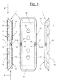
- Figur 1:
- einen Steckverbinder in der Draufsicht von unten und in zwei geklappten Seitenansichten,
- Figur 2:
- eine vergrößerte und abgebrochene Seitenansicht des Steckverbinders mit einem Anschlag und einer Auflaufschräge sowie einem zusätzlichen Festanschlag,
- Figur 3:
- eine Stirnansicht des Steckverbinders von
Figur 1, - Figur 4:
- zwei vergrößerte und abgebrochene Detailansichten der Anschläge mit Auflaufschrägen,
- Figur 5:
- eine Variante zu
Figur 1 mit Anschlägen und einer geraden Stegkante, - Figur 6:
- eine abgebrochene und vergrößerte
Detaildarstellung zu
Figur 5, - Figur 7:
- einen weiteren Steckverbinder mit einem Dichtkörper in einer Ansicht von unten,
- Figur 8:
- eine geklappte Seitenansicht des Steckverbinders
von
Figur 7, - Figur 9:
- den
Steckverbinder von Figur 8 in Stirnansicht, - Figur 10:
- eine Stirnansicht des Steckverbinders in Montagestellung in den Hohlprofilen und
- Figur 11:
- eine Draufsicht auf die Montagestellung des Steckverbinders.
- Figure 1:
- a connector in top view from below and in two folded side views,
- Figure 2:
- an enlarged and broken side view of the connector with a stop and a ramp and an additional fixed stop,
- Figure 3:
- 2 shows an end view of the connector from FIG. 1,
- Figure 4:
- two enlarged and broken-off detailed views of the stops with run-on slopes,
- Figure 5:
- 1 variant with stops and a straight web edge,
- Figure 6:
- a broken and enlarged detail view of Figure 5,
- Figure 7:
- another connector with a sealing body in a view from below,
- Figure 8:
- 4 shows a folded side view of the connector from FIG. 7,
- Figure 9:
- 8 in front view,
- Figure 10:
- an end view of the connector in the mounting position in the hollow profiles and
- Figure 11:
- a plan view of the mounting position of the connector.
Figur 1 bis 11 zeigen einen Steckverbinder (1) in Form eines Geradverbinders, der für Hohlprofile (2,3) von Abstandshaltern für Isolierglasscheiben vorgesehen ist. Figur 5 bis 7 zeigen den Steckverbinder (1) in Verbindung mit solchen Hohlprofilen (2,3). Alternativ kann es sich auch um andere Hohlprofile, z.B. Sprossen für Isolierglasscheiben handeln.Figures 1 to 11 show a connector (1) in the form of a straight connector for hollow profiles (2,3) from Spacers for insulating glass panes is provided. Figures 5 to 7 show the connector (1) in connection with such hollow profiles (2,3). Alternatively, it can also around other hollow profiles, e.g. Sprouts for Act insulating glass panes.
Der von den gezeigten Hohlprofilen (2,3) gebildete Abstandshalter dient zur Distanzierung zweier Einzelscheiben einer Isolierglasscheibe (nicht dargestellt). Die gezeigten Hohlprofile (2,3) sind vorzugsweise besonders dünnwandig und bestehen aus Edelstahl. Sie haben gegenüber dem bisher eingesetzten dickwandigeren Hohlprofilen aus Leichtmetall, insbesondere Aluminium oder Aluminiumlegierungen, einen deutlich verringerten Wärmeleitwert und sind für höherwertige Wärmeschutzverglasungen besonders geeignet. Derartige Hohlprofile (2,3) haben z.B. eine Wanddicke von ca. 0, 2 mm.The one formed by the hollow profiles (2, 3) shown Spacers are used to distance two Individual panes of an insulating glass pane (not ) Shown. The hollow profiles (2, 3) shown are preferably particularly thin-walled and consist of Stainless steel. You have compared to the previously used thick-walled hollow profiles made of light metal, in particular Aluminum or aluminum alloys, clearly reduced thermal conductivity and are for higher quality Thermal protection glazing particularly suitable. such Hollow profiles (2,3) have e.g. a wall thickness of approx. 0.2 mm.
Die Hohlprofile (2,3) haben im gezeigten Ausführungsbeispiel eine im wesentlichen rechteckige Querschnittsform. Im Eckbereich (5) (vgl. Figur 10) zwischen dem am Abstandshalterrahmen nach außen weisenden Dachbereich (4) und den Seitenwänden kann eine Abschrägung oder Abrundung vorhanden sein. Der gegenüberliegende Profilboden liegt an der Rahmeninnenseite (7) des Abstandshalterrahmens und weist zum Scheibeninnenraum. Zwischen dem Boden und den Seitenwänden der Hohlprofile (2,3) können schärfere Ecken vorhanden sein. Gegebenenfalls können sich die Seitenwände über den Boden hinaus auch in längslaufende Stege fortsetzen. Die gezeigte Querschnittsform der Hohlprofile (2,3) kann jedoch in beliebiger Weise variieren und anders als gezeigt ausgebildet sein.The hollow profiles (2,3) have shown in the Embodiment a substantially rectangular Cross-sectional shape. In the corner area (5) (see Figure 10) between the one pointing outwards on the spacer frame Roof area (4) and the side walls can be chamfered or rounding off. The opposite Profile floor is on the inside of the frame (7) of the Spacer frame and points to the window interior. Between the bottom and the side walls of the hollow profiles (2,3) there may be sharper corners. If necessary, the side walls can be above the floor continue also into longitudinal webs. The shown cross-sectional shape of the hollow profiles (2,3) however vary in any way and other than shown to be trained.
Der Steckverbinder (1) ist in seiner Querschnittsform an die Gestalt der Hohlprofile (2,3) angepaßt. Er hat im gezeigten Ausführungsbeispiel im Querschnitt eine U-Form mit einem Mittelsteg (10) und zwei senkrecht davon abstehenden Seitenstegen (11). Der Mittelsteg (10) weist zum Dachbereich (4). Zwischen dem Mittelsteg (10) und den Seitenstegen (11) kann ein schräger oder runder Übergang (14) vorhanden sein. Abweichend vom gezeigten Ausführungsbeispiel kann der Steckverbinder (1) auch einen kastenförmigen geschlossenen Querschnitt haben. In Anpassung an die Hohlprofilform kann seine Gestalt außerdem noch in anderer Weise variieren.The connector (1) is in its cross-sectional shape adapted the shape of the hollow profiles (2,3). He has in Embodiment shown in cross section a U-shape with a central web (10) and two perpendicular to it protruding side webs (11). The central web (10) points to the roof area (4). Between the central web (10) and the Side bars (11) can be an oblique or round transition (14) be present. Deviating from the shown The connector (1) can also be an exemplary embodiment have box-shaped closed cross-section. In Adaptation to the hollow profile shape can change its shape also vary in other ways.
Der gezeigte Steckverbinder (1) besteht vorzugsweise aus Metall. Er kann aber auch aus Kunststoff oder beliebig anderen geeigneten Werkstoffen sowie auch aus Verbundwerkstoffen bestehen. Im gezeigten Ausführungsbeispiel ist er als Stanz- und Biegeteil aus Stahlblech ausgeführt. Vorzugsweise besteht er aus einem Bandstahl, der nach dem Stanzen und Biegen vergütet und galvanisch behandelt wird.The connector (1) shown preferably consists of Metal. But it can also be made of plastic or any other suitable materials as well Composites exist. In the shown The embodiment is made of stamped and bent parts Made of sheet steel. It preferably consists of a Steel strip that is tempered after stamping and bending and is galvanically treated.
Der Steckverbinder (1) hat an der Verbindungsstelle oder Stoßstelle (6), die zugleich vorzugsweise die querlaufende Mittellinie des Steckverbinders (1) bildet, einen Mittenanschlag. Der Mittenanschlag besteht zumindest aus zwei Anschlägen (17,18), an denen zumindest die Stirnwand des ersten aufgeschobenen Hohlprofils (2,3) anschlägt. Zusätzlich können gemäß Figur 1 bis 4 Festanschläge (15,16) vorhanden sein. Durch den Mittenanschlag steckt der Steckverbinder (1) jeweils hälftig in den beiden Hohlprofilen (2,3). Er ermöglicht ein dichtes Aneinanderstoßen der Hohlprofile (2,3) an der Verbindungsstelle (6) und verhindert weitgehend die Bildung von Fugen an dieser Stelle. Dies verbessert einerseits die optische Erscheinung des Abstandshalters und verhindert andererseits, daß das innenliegende granulierte Trocknungsmittel an der Verbindungsstelle (6) austritt und in den Scheibeninnenraum gelangt.The connector (1) has at the connection point or Joint (6), which is also preferably the transverse one Center line of the connector (1) forms one Center stop. The center stop consists at least of two stops (17, 18) on which at least the end wall of the first pushed-on hollow profile (2,3). 1 to 4 fixed stops can also be used (15:16) be present. Through the center stop half of the connector (1) in each of the two Hollow profiles (2,3). It enables a tight Butting of the hollow profiles (2,3) on the Junction (6) and largely prevents Formation of joints at this point. This improves on the one hand the optical appearance of the spacer and on the other hand prevents the inside granulated drying agent at the connection point (6) emerges and gets into the window interior.
Wie Figur 3, 4, 9 und 10 verdeutlichen, sind die Anschläge (17,18) am vorerwähnten schrägen Übergang (14) zwischen Mittel- und Seitensteg (10,11) angeordnet. Die Anschläge (17,18) weisen dadurch schräg nach außen und haben eine nach außen gewölbte runde konvexe Querschnittsform (25). Im gezeigten Ausführungsbeispiel sind sie freigestanzt und ausgestemmt.As shown in Figures 3, 4, 9 and 10, the stops (17,18) at the aforementioned oblique transition (14) between Middle and side web (10,11) arranged. The attacks (17,18) point obliquely outwards and have one round convex cross-sectional shape curved outwards (25). In the exemplary embodiment shown, they are punched out and chiselled.
Die Anschläge (17,18) sind als gegeneinander gerichtete und einseitig wirkende vorzugsweise feste Anschläge ausgebildet. Sie weisen in entgegengesetzte Richtungen, wobei jeder Anschlag (17,18) nur auf ein Hohlprofil (2,3) einwirkt. Wie Figur 11 verdeutlicht, liegt das Hohlprofil (2) am Anschlag (17) an und das Hohlprofil (3) am Anschlag (18). Die Anschläge (17,18) sind dazu am vorderen und zur Verbindungsstelle (6) weisenden Ende quer zur Verbinderlängsachse gerade abgeschnitten und bilden dadurch eine Anschlagkante (19). Die Anschläge (17,18) sind im Bereich der Verbindungsstelle (6) axial zueinander versetzt angeordnet und liegen einander an der Verbindungsstelle (6) gegenüber. Sie können dabei um eine kleine Distanz von der Verbindungsstelle (6) rückversetzt sein.The stops (17, 18) are directed towards each other and one-way preferably fixed stops educated. They point in opposite directions, each stop (17, 18) only on a hollow profile (2, 3) acts. As illustrated in FIG. 11, the hollow profile lies (2) on the stop (17) and the hollow profile (3) on the stop (18). The stops (17, 18) are on the front and Connection point (6) facing end transverse to Straight cut longitudinal connector axis and form thereby a stop edge (19). The attacks (17,18) are axially to each other in the area of the connection point (6) staggered and lie against each other Junction (6) opposite. You can order one set back a small distance from the connection point (6) his.
Die Anschläge (17,18) haben jeweils an ihrer Rückseite eine Auflaufschräge (24), die von der Oberseite des Übergangs (14) jeweils zur Anschlagkante (19) und zur Verbindungsstelle (6) hin keilförmig ansteigt. Vor den Anschlagkanten (19) der Anschläge (17,18) befindet sich jeweils eine freigestanzte Ausnehmung (21). Die Ausnehmung (21) erleichtert das Ausstemmen und ist zur Bildung einer geraden Anschlagkante (19) vorteilhaft. The stops (17, 18) each have on their back a ramp (24) from the top of the Transition (14) to the stop edge (19) and Connection point (6) rises wedge-shaped. Before Stop edges (19) of the stops (17, 18) is located each a punched-out recess (21). The recess (21) facilitates the chiselling and is to form a straight stop edge (19) advantageous.
Die Wölbungen (25) der Anschläge (17,18) bzw. ihrer Anlaufschrägen (24) können als kleine Buckel ausgebildet sein, die schmäler als der Übergang (14) sind. Figur 3 und 4 zeigen eine solche Ausbildung. In einer anderen Variante, wie sie in Figur 9 und 10 dargestellt ist, sind die Wölbungen (25) größer und gehen mit ihren seitlichen Flanken in den Mittelsteg (10) bzw. den angrenzenden Seitensteg (11) über.The curvatures (25) of the stops (17, 18) or their Run-up slopes (24) can be designed as small humps be narrower than the transition (14). Figure 3 and 4 show such training. In another Variant, as shown in Figures 9 and 10, are the bulges (25) larger and go with their side Flanks in the central web (10) or the adjacent Side bridge (11) over.
Die zusätzlichen Festanschläge (15,16) sind jeweils an einem Rand (12) der Seitenstege (11) angeordnet. Vorzugsweise ist dies der zur Rahmeninnenseite (7) weisende untere Stegrand. Die Festanschläge (15,16) wirken jeweils nur in einer Richtung, wobei diese Wirkrichtungen entgegengesetzt sind. Die Festanschläge (15,16) sind im Bereich der Verbindungsstelle (6) axial zueinander versetzt angeordnet und liegen einander an der Verbindungsstelle (6) gegenüber. Der eine rechte Festanschlag (15) wirkt mit dem Hohlprofil (2) und der andere Festanschlag (16) mit dem Hohlprofil (3) zusammen.The additional fixed stops (15, 16) are on an edge (12) of the side webs (11) arranged. This is preferably the one towards the inside of the frame (7) pointing lower web edge. The fixed stops (15, 16) are effective only in one direction, these directions of action are opposite. The fixed stops (15, 16) are in Area of the connection point (6) axially to each other staggered and lie against each other Junction (6) opposite. One right Fixed stop (15) acts with the hollow profile (2) and other fixed stop (16) together with the hollow profile (3).
Wie Figur 2 verdeutlicht, haben die Festanschläge (15,16) vorzugsweise die Form von im wesentlichen dreieckigen Anschlagnasen und besitzen an der zur Verbindungsstelle (6) weisenden Vorderseite eine gerade Anschlagkante (19), die im wesentlichen quer zur Verbinderlängsachse verläuft. Die Anschlagkante (19) kann in eine kleine Freistanzung auslaufen. An der Rückseite haben die Anschlagnasen (15,16) eine vom Stegrand (12) ansteigende schräge Flanke (20), auf der das jeweils von der Rückseite her aufgeschobene Hohlprofil (2,3) aufgleitet. Die Formgebung kann entsprechend des DE-U-94 11 067 sein.As shown in Figure 2, the fixed stops (15, 16) preferably the shape of substantially triangular Stop lugs and have at the connection point (6) facing the front a straight stop edge (19), which runs essentially transversely to the longitudinal axis of the connector. The stop edge (19) can be cut in a small way leak. The stop lugs have on the back (15, 16) an inclined flank rising from the web edge (12) (20), on the back of each Slid on hollow profile (2,3). The shape can be according to DE-U-94 11 067.
In der gezeigten Ausführungsform stehen die Anschlagnasen (15,16) vom unteren Stegrand (12) vor und liegen in Verlängerung der Seitenstege (11). Alternativ können die Festanschläge (15,16) auch schräg oder seitlich ausgestellt sein und dadurch über die Seitenfläche der Stege (11) seitlich vorstehen.In the embodiment shown, the stop lugs are (15,16) from the lower web edge (12) and are in Extension of the side bars (11). Alternatively, the Fixed stops (15, 16) also diagonally or laterally be issued and thus over the side surface of the Project the webs (11) to the side.
Am anderen Randbereich (13) der Seitenstege (11) sind die Anschläge (17,18) angeordnet. Über dem Festanschlag (15) befindet sich der Anschlag (17) und über dem Festanschlag (16) der andere Anschlag (18). Wie Figur 2 verdeutlicht, sind die Festanschläge (15,16) und ihre am gleichen Seitensteg (11) zugeordneten Anschläge (17,18) jeweils an der Verbindungsstelle (6) gegenüberliegend angeordnet. Die Festanschläge (15,16) liegen auf der einen Seite der Verbindungsstelle (6) und die Anschläge (17,18) auf der gegenüberliegenden Seite.At the other edge area (13) of the side webs (11) are Stops (17, 18) arranged. Above the fixed stop (15) is the stop (17) and above the fixed stop (16) the other stop (18). As Figure 2 illustrates, the fixed stops (15, 16) and theirs are the same Side web (11) assigned stops (17, 18) each the connection point (6) arranged opposite. The Fixed stops (15, 16) lie on one side of the Junction (6) and the stops (17, 18) on the opposite side.
Wie Figur 1 und 2 verdeutlichen, weisen die Anschlagkanten (19) der jeweils am gleichen Seitensteg (11) befindlichen Festanschläge (15, 16) und Anschläge (17,18) in entgegengesetzte Richtungen. Die Anschlagkanten (19) können, wie im Ausführungsbeispiel gezeigt, gegenüber der Verbindungsstelle (6) oder Mittellinie etwas axial zurückversetzt angeordnet sein. Sie können alternativ aber auch auf gleicher Höhe liegen.As shown in Figures 1 and 2, the stop edges (19) the one located on the same side web (11) Fixed stops (15, 16) and stops (17, 18) in opposite directions. The stop edges (19) can, as shown in the embodiment, compared to Junction (6) or center line somewhat axially be set back. Alternatively, you can are also at the same level.
In ihrer Anschlagfunktion wirken die gleichgerichteten Festanschläge (15,16) und Anschläge (17,18) sowie deren Auflaufschrägen (24) zusammen. Dies bedeutet, daß der Festanschlag (15) mit dem am anderen Seitensteg (11) befindlichen Anschlag (18) zusammenwirkt und der Festanschlag (16) mit dem ebenfalls diagonal gegenüberliegenden Anschlag (17). Diese in ihrer Anschlagfunktion zusammenwirkenden Anschläge (15,18) und (16,17) liegen mit ihren Anschlagkanten (19) axial gesehen auf gleicher Höhe. Die aufgeschobenen Hohlprofile (2,3) schlagen dadurch an jeweils zwei diagonal über den Profilquerschnitt gegenüberliegenden Stirnwandecken an. In their stop function, the rectified act Fixed stops (15, 16) and stops (17, 18) and their Sloping slopes (24) together. This means that the Fixed stop (15) with the one on the other side web (11) located stop (18) cooperates and the Fixed stop (16) with the also diagonally opposite stop (17). This in their Stop function interacting stops (15, 18) and (16, 17) lie axially with their stop edges (19) at the same height. The pushed-on hollow profiles (2,3) thereby hitting two diagonally across the Profile cross-section on opposite end wall corners.
Wie Figur 1 in der linken Darstellung verdeutlicht, wird zunächst das Hohlprofil (2) in Richtung (8) auf den Steckverbinder (1) aufgeschoben. Dabei gleitet es im außenliegenden Eckbereich (5) auf der Auflaufschräge (24) des Anschlags (17) und deren schräger Flanke auf. An der diagonal gegenüberliegenden Ecke gleitet das Hohlprofil (2) auf der rückwärtigen Flanke (20) des Festanschlags (16) (nicht sichtbar) auf. Im Bereich der Verbindungsstelle bzw. Mittellinie (6) schlägt das Profil (2) im Bodenbereich am Festanschlag (15) und im diagonal gegenüberliegenden Eckbereich (5) am Anschlag (18) an.As illustrated in the left-hand illustration in FIG first the hollow profile (2) in the direction (8) on the Plug connector (1) pushed on. It slides in outer corner area (5) on the ramp (24) of the stop (17) and their oblique flank. At the the hollow profile slides diagonally opposite the corner (2) on the rear flank (20) of the fixed stop (16) (not visible). In the field of Connection point or center line (6) beats the profile (2) in the floor area at the fixed stop (15) and in the diagonal opposite corner area (5) at the stop (18).
Das zuvor erfolgte Aufgleiten des Hohlprofils (2) auf der Auflaufschräge (24) des Anschlags (17) bewirkt, daß das Hohlprofil (2) angehoben und mit dem Boden gegen den unteren Stegrand (12) gepreßt wird. Dadurch kommt die Hohlprofilstirnwand sicher in Anschlag mit den Anschlagkanten (19) des Anschlags (18) und des Festanschlags (15).The previous sliding of the hollow profile (2) on the Run-up slope (24) of the stop (17) causes that Hollow profile (2) raised and with the floor against the lower web edge (12) is pressed. That’s why Hollow profile end wall securely in contact with the Stop edges (19) of the stop (18) and the Fixed stop (15).
Wie Figur 2 verdeutlicht, stehen die Festanschläge (15,16) nur um ein geringfügiges Maß über die zugeordneten Stegränder (12) nach außen vor. Dieser Überstand ist in etwa so groß wie die Profilwanddicke und beträgt im gezeigten Ausführungsbeispiel ca. 0,2 mm. Die Erhöhung der Auflaufschrägen kann wesentlich größer sein. In der gezeigten Ausführungsform beträgt sie z.B. am Scheitel und an der Anschlagkante (19) ca. 0,5 bis 1 mm.As shown in Figure 2, the fixed stops (15, 16) only a slight amount beyond the assigned Web edges (12) to the outside. This supernatant is in about as large as the profile wall thickness and is in embodiment shown about 0.2 mm. The increase in Sloping slopes can be much larger. In the shown embodiment it is e.g. at the crown and at the stop edge (19) approx. 0.5 to 1 mm.
Das anschließend aufgeschobene zweite Hohlprofil (3) schlägt an der Stirnseite des ersten Hohlprofils (2) oder an den zugehörigen Anschlägen (16,17) des Steckverbinders (1) an. Wenn die Anschläge (15,16) und (17,18) gegenüber der Verbindungsstelle (6) axial zurückversetzt angeordnet sind, erfolgt der Anschlag am zuvor aufgeschobenen Hohlprofil (2). The second hollow profile then pushed on (3) beats on the face of the first hollow profile (2) or on the associated stops (16, 17) of the connector (1). If the stops (15,16) and (17,18) opposite the connection point (6) is axially set back are, the stop is made on the previously pushed Hollow section (2).
Figur 5 und 6 zeigen eine Variante des Steckverbinders (1) von Figur 1 bis 4. Die Ausbildung und Anordnung der Anschläge (17,18) und ihrer Auflaufschrägen (24) ist in beiden Ausführungsformen die gleiche. Außerdem ist der hierdurch erzielte Effekt der Stabilisierung des Eckbereichs (5) der Hohlprofile (2,3) einerseits und des sicheren Auftreffens auf die Anschlagkanten (19) der Anschläge (17,18) andererseits gegeben und erreicht. In Figur 5 und 6 sind in Variation zum vorbeschriebenen Ausführungsbeispiel die Festanschläge (15,16) weggelassen. Statt dessen hat der untere Stegrand (12) eine zumindest im Bereich der Verbindungsstelle (6) gerade und durchgehende Kante (26). Mit dieser Kante (26) stützt sich der Steckverbinder (1) am Boden (7) der Hohlprofile (2,3) ab. Durch die gerade durchgehende Kante ist die Abstützfunktion besonders gut. Die am Übergang (14) befindlichen Anschläge (17,18) mit ihren Auflaufschrägen (24) können dadurch die Hohlprofile (2,3) besonders gut stabilisieren und ausrichten.FIGS. 5 and 6 show a variant of the connector (1) from Figure 1 to 4. The formation and arrangement of Stops (17, 18) and their run-up slopes (24) is in both embodiments the same. In addition, the hereby achieved stabilization effect Corner area (5) of the hollow profiles (2,3) on the one hand and the sure hitting the stop edges (19) of the On the other hand, stops (17, 18) were given and reached. In Figures 5 and 6 are in variation of the above Embodiment omitted the fixed stops (15, 16). Instead, the lower web edge (12) has at least one in the area of the connection point (6) straight and continuous edge (26). This edge (26) supports itself the connector (1) on the bottom (7) of the hollow profiles (2, 3) from. Due to the straight continuous edge it is Support function particularly good. At the transition (14) located stops (17, 18) with their run-on slopes (24), the hollow profiles (2, 3) are particularly good at this stabilize and align.
Für den sicheren Halt des Steckverbinders (1) in den aufgeschobenen Hohlprofilen (2,3) sorgen ein oder mehrere Rückhalteelemente (22,23), die unterschiedlich ausgebildet sein können. Im gezeigten Ausführungsbeispiel sind an den unteren Stegrändern (12) der Seitenstege (11) jeweils freigestanzte und nach unten sowie seitlich ausgebogene Federnasen (23) angeordnet. Diese können für sich allein bereits genügen. Zusätzlich oder alternativ können auch am zur Rahmenaußenseite weisenden Mittelsteg (10) mehrere Öffnungen (22) vorhanden sein, in die Verstemmungen am Dachbereich (4) der Hohlprofile (2,3) eingreifen und eine formschlüssige Verbindung bilden. Diese Ausbildung entspricht z.B. der DE-A-43 35 039. Alternativ oder zusätzlich können auch ausgestellte Federnasen am Mittelsteg (10) vorhanden sein. Der Steckverbinder (1) kann an den Stirnseiten geschlossen oder offen sein. Er kann ansonsten eine beliebig andere Gestalt und Ausbildung als im gezeigten Ausführungsbeispiel haben.For a secure hold of the connector (1) in the pushed on hollow profiles (2,3) provide one or more Retaining elements (22, 23), which are designed differently could be. In the embodiment shown, the lower web edges (12) of the side webs (11) each punched out and bent downwards and laterally Spring lugs (23) arranged. These can be done on their own already suffice. Additionally or alternatively, on several to the center outside of the central web (10) Openings (22) exist in the caulking on Intervene roof area (4) of the hollow profiles (2,3) and one form a positive connection. This training corresponds to e.g. DE-A-43 35 039. Alternatively or In addition, spring noses can be issued on Middle web (10) should be available. The connector (1) can be closed or open at the front. He can otherwise have any other shape and training than in the embodiment shown.
Figur 7 bis 11 zeigen eine weitere Variante des Steckverbinders (1). Im gezeigten Ausführungsbeispiel hat der Steckverbinder (1) ebenfalls einen im wesentlichen U-förmigen Querschnitt. Seine Wandung besteht aus einem Mittelsteg (10) und zwei senkrechten oder schrägen Seitenstegen (11). An den Stirnseiten (31) ist der Mittelsteg (10) schräg abgewinkelt und bildet in diesem Bereich ebenfalls eine im wesentlichen geschlossene Wandung. Die Stege (10,11) umschließen miteinander einen Hohlraum, (32), der nach einer Seite mit seiner Hohlraumöffnung offen ist.FIGS. 7 to 11 show a further variant of the Connector (1). In the embodiment shown the connector (1) also essentially one U-shaped cross section. Its wall consists of one Center bar (10) and two vertical or sloping ones Side bars (11). At the end faces (31) is the Center web (10) angled obliquely and forms in this Area also a substantially closed Wall. The webs (10, 11) enclose one another Cavity, (32) facing one side with its Cavity opening is open.
In dem Hohlraum (32) ist ein Dichtkörper (28) angeordnet, der z.B. als quaderförmiges Kissen ausgebildet ist und durch eine Klebeverbindung oder in sonstiger beliebig geeigneter Weise an der Innenseite des Mittelsteges (10) fixiert ist. Der Dichtkörper (28) kann an die Form des Hohlraumes (32) angepaßt sein und diesen vollständig ausfüllen. Der Dichtkörper (28) besteht aus einem elastischen Material, z.B. einem Kunststoffschaum. Der Dichtköper (28) ist so groß bemessen, daß er durch die Hohlraumöffnung (32) ein Stück nach außen ragt und damit über die Kontur des Steckverbinders (1) bzw. über den unteren Rand der Seitenstege (11) vorsteht.A sealing body (28) is arranged in the cavity (32), e.g. is designed as a rectangular pillow and by an adhesive connection or in any other way suitably on the inside of the central web (10) is fixed. The sealing body (28) can match the shape of the Be adapted cavity (32) and this completely to complete. The sealing body (28) consists of a elastic material, e.g. a plastic foam. The Sealing body (28) is so large that it through the Cavity opening (32) protrudes a bit outwards and thus over the contour of the connector (1) or over the protrudes lower edge of the side webs (11).
Der Dichtkörper (28) befindet sich zumindest im Bereich der Verbindungsstelle (6), die beim gezeigten Steckverbinder vorzugsweise mit dessen Mitte in Längsrichtung identisch ist. Wie Figur 9 und 10 verdeutlichen, wird der Dichtkörper (28), der anfangs noch über die Seitenstege (11) vorstand, bei der Montage des Steckverbinders in den Hohlprofilen (2,3) komprimiert und liegt dadurch mit Druck im Bereich der Hohlraumöffnung (32) an der Innenwand der Hohlprofile (2,3) an. Er übergreift die Verbindungsstelle (6) und dichtet diese ab. The sealing body (28) is at least in the area the connection point (6) shown in the Connector preferably with its center in Longitudinal direction is identical. Like Figures 9 and 10 illustrate, the sealing body (28), which is initially board over the side webs (11) when installing the Connector in the hollow profiles (2,3) compressed and lies with pressure in the area of the cavity opening (32) on the inner wall of the hollow profiles (2,3). He engages over the connection point (6) and seals it.
Im Abstandshalterrahmen befindet sich ein granuliertes Trocknungsmittel (30), das mit dem Innenraum der Isolierglasscheibe über eine Perforation in den Profilen in Verbindung steht. Durch die geschlossenen Stirnseiten (31) und zusätzlich durch das Dichtkissen (28) wird ein Austritt dieses Granulats (30) an der Verbindungsstelle (6) verhindert.There is a granulated in the spacer frame Desiccant (30) that matches the interior of the Insulating glass pane over a perforation in the profiles communicates. Through the closed end faces (31) and additionally through the sealing cushion (28) This granulate (30) emerges at the connection point (6) prevented.
Wie Figur 9 und 10 verdeutlichen, wird der Steckverbinder (1) derart in den Hohlprofilen (2,3) montiert, daß sein Mittelsteg (10) zum außenliegenden Dachbereich (4) der Hohlprofile (2,3) weist. Die Hohlraumöffnung (32) weist zum Bodenbereich (7) der Hohlprofile (2,3) hin. Der Bodenbereich (7) ist zum Scheibeninnenraum hin gewendet.As shown in Figures 9 and 10, the connector (1) so mounted in the hollow profiles (2,3) that be Middle web (10) to the outer roof area (4) of the Has hollow profiles (2,3). The cavity opening (32) has towards the bottom area (7) of the hollow profiles (2, 3). The The floor area (7) is turned towards the interior of the window.
Für die Mittenfindung des Steckverbinders (1) bei der Montage sind zumindest die vorbeschriebenen Anschläge (17,18) und gegebenenfalls weitere Anschläge in beliebig geeigneter Ausführung vorhanden. Der in Figur 10 gezeigte rechte Anschlag (17) wirkt mit seiner zur Verbindungsstelle (6) weisenden Vorderseite oder Anschlagkante (19) als Stop für das in der Zeichenebene von hinten aufgeschobene Hohlprofil (2) und bildet mit seiner Rückseite die Aufgleitschräge (24) für das andere vordere, geschnitten dargestellte Hohlprofil (3). Der linke Anschlag (18) ist entsprechend ausgebildet und verdreht angeordnet. Dadurch wirkt er als Anschlag für das Hohlprofil (3) und als Aufgleitschräge (24) für das Hohlprofil (2).For centering the connector (1) at the Assembly are at least the stops described above (17,18) and any other stops in any suitable version available. The one shown in Figure 10 right stop (17) works with his Connection point (6) facing front or Stop edge (19) as a stop for that in the drawing plane hollow profile (2) pushed on from behind and forms with the back of the sliding slope (24) for the other front, sectioned hollow profile (3). The left stop (18) is designed accordingly and twisted arranged. He acts as a stop for that Hollow profile (3) and as a sliding slope (24) for the Hollow section (2).
Der Steckverbinder (1) hat am Mittelsteg (10) im Bereich der Verbindungsstelle (6) einen zum Hohlraum (32) hin gerichteten Vorsprung (29), der z.B. als eine plattenförmige Ausprägung ausgebildet ist. Dieser Vorsprung (29) wölbt den Dichtkörper (28) an der Verbindungsstelle (6) zusätzlich durch die Hohlraumöffnung (32) nach außen. Figur 8 zeigt diese Auswirkung. Durch diese Wölbung wird der Dichtkörper (28) an der Verbindungsstelle (6) bei der Montage zusätzlich verdichtet und entwickelt an dieser kritischen Stelle eine erhöhte Anpreßkraft und Dichtwirkung.The connector (1) has in the area on the central web (10) the connection point (6) towards the cavity (32) directed projection (29) which e.g. as one plate-shaped expression is formed. This Projection (29) bulges the sealing body (28) on the Connection point (6) through the cavity opening (32) outwards. Figure 8 shows this effect. By this curvature becomes the sealing body (28) on the Connection point (6) additionally during assembly condenses and develops one at this critical point increased contact pressure and sealing effect.
Wie Figur 8 weiter verdeutlicht, haben die Seitenstege (11) im Bereich der Verbindungsstelle (6) an ihrem freien Rand (12) eine zurückspringende Ausnehmung (27). Durch diese Ausnehmung (27) kann bei der Montage der komprimierte Dichtkörper (28) dringen und in dichtenden Kontakt mit den Seitenwänden der Hohlprofile (2,3) gelangen. Figur 10 zeigt diesen Effekt ebenfalls.As Figure 8 further illustrates, the side bars have (11) in the area of the connection point (6) at its free Edge (12) a recessed recess (27). By this recess (27) can be used during assembly of the compressed sealing body (28) penetrate and in sealing Contact with the side walls of the hollow profiles (2,3) reach. Figure 10 also shows this effect.
Der Dichtkörper (28) kann zusätzlich auch im Bereich der Anschläge (17,18) durch die Ausnehmungen oder Freischnitte (21) nach außen treten und diese Öffnungen zusätzlich dichtend verschließen bzw. in Dichtkontakt mit den Hohlprofilen (2,3) treten.The sealing body (28) can also in the area of Stops (17, 18) through the recesses or free cuts (21) step out and these openings additionally seal tightly or in sealing contact with the Kick hollow profiles (2,3).
Der Steckverbinder (1) kann außerdem ein oder mehrere federnde oder reibende Rückhalteelemente (23) aufweisen. In der gezeigten Ausführungsform handelt es sich um freigeschnittene und seitlich ausgebogene Rückhaltenasen (23), die jeweils in Einstiegsrichtung abgewinkelt sind und sich bei einem Zurückziehen in den Hohlprofilen (2,3) verkrallen. Im Bereich der Rückhaltenasen (23) können ebenfalls Ausnehmungen oder Freischnitte (21) vorhanden sein, durch die der Dichtkörper (28) bei der Montage greift.The connector (1) can also one or more Have resilient or rubbing retaining elements (23). The embodiment shown is cut-out and laterally curved retention lugs (23), which are each angled in the entry direction and when retracting in the hollow profiles (2,3) dig. In the area of the retaining lugs (23) recesses or free cuts (21) are also present be through which the sealing body (28) during assembly attacks.
Im weiteren kann der Steckverbinder (1) auch noch andere Befestigungsmöglichkeiten besitzen. In der gezeigten Ausführungsform hat er am Mittelsteg (10) mehrere der vorbeschriebenen Verstemmöffnungen (22) mit geeigneter Formgebung, durch die nach der Montage Wandverstemmungen im Dachbereich (4) der Hohlprofile (2,3) formschlüssig eingreifen. Die Wandverstemmungen werden durch von außen angesetzte Stempel erzielt, die die Hohlprofilwandung durch die Verstemmöffnungen (22) in den Hohlraum (32) und den Dichtkörper (28) drücken. Der Dichtkörper (28) kann somit im wesentlichen alle Öffnungen am Steckverbinder (1) bei der Montage dichtend verschließen.In addition, the connector (1) can also be other Have attachment options. In the shown Embodiment he has several of the middle web (10) above described caulking openings (22) with suitable Shape, through which wall caulking after assembly in the roof area (4) of the hollow profiles (2, 3) with a positive fit intervention. The wall caulking is done from the outside attached stamp achieved the hollow profile wall through the caulking openings (22) into the cavity (32) and press the sealing body (28). The sealing body (28) can essentially all openings on the connector (1) seal tightly during assembly.
Abwandlungen der gezeigten Ausführungsformen sind in verschiedener Weise möglich. Zum einen können die Festanschläge (15,16) eine andere Form, Lage und Ausrichtung haben. Desgleichen können die keilförmigen Auflaufschrägen (24) bzw. die Anschläge (17,18) an den Steckverbinder (1) angeformt oder aufgesetzt sein. Im Bereich des Mittelstegs (10) können weitere Anschläge vorhanden sein, die z.B. auch in diesem Bereich vorhandene Wandverformungen der Hohlprofile (2,3) ausrichten und korrigieren. Hierzu sind beispielsweise auch nahe der Verbindungsstelle (6) angeordnete Federnasen geeignet. Außerdem kann der Steckverbinder (1) einen geschlossenen Querschnitt mit zwei Mittelstegen besitzen, wobei entsprechend auch am zweiten Mittelsteg Federnasen, Anschläge und dergleichen angeordnet sein können.Variations of the shown embodiments are in possible in different ways. For one, they can Fixed stops (15, 16) a different shape, location and Have alignment. Likewise, the wedge-shaped Run-up slopes (24) or the stops (17, 18) on the Plug connector (1) can be formed or attached. in the The area of the central web (10) can have further stops be present, e.g. existing in this area too Align the wall deformations of the hollow profiles (2,3) and correct. For this purpose, for example, are also close to Connection point (6) arranged spring lugs suitable. In addition, the connector (1) can be closed Have cross-section with two central webs, whereby accordingly also on the second central web spring noses, Stops and the like can be arranged.
Der Steckverbinder (1) kann auch mehrere Hohlräume (32) aufweisen, die gegebenenfalls alle mit einem entsprechend gestalteten Dichtköper (28) zumindest teilweise gefüllt sind. Ferner ist die Querschnittsgestaltung des Steckverbinders (1) beliebig. Ferner kann ein zusätzlicher Dichtkörper auch im Bereich des Vorsprungs (29) außenseitig angeordnet sein. Der Dichtkörper (28) kann eine verkürzte Form haben, die im wesentlichen die Verbindungsstelle (6) und einen gewissen beidseitigen Sicherheitsbereich überdeckt. Der Dichtkörper (28) läßt sich zudem mit seitlichem Übermaß ausbilden, so daß er schon bei der Befestigung im Steckverbinder (1) durch die Ausnehmungen (27,21) tritt. Er kann allerdings auch wie in der gezeigten Ausführungsform genau zwischen die Seitenstege (11) eingepaßt sein oder sogar schmäler sein. Variabel sind zudem die Ausbildung und Anordnung der Anschläge (17,18) und der Rückhalteelemente (23,22). Der Steckverbinder (1) könnte an den Stirnseiten (31) auch offen sein. The connector (1) can also have several cavities (32) have, if necessary, all with a corresponding designed sealing body (28) at least partially filled are. Furthermore, the cross-sectional design of the Any connector (1). Furthermore, an additional Sealing body also in the area of the projection (29) be arranged on the outside. The sealing body (28) can have a shortened form, which is essentially the Junction (6) and a certain bilateral Security area covered. The sealing body (28) leaves educate yourself with lateral oversize so that he already when fastening in the connector (1) by the Recesses (27.21) occurs. However, it can also be used as in the embodiment shown exactly between the Side webs (11) to be fitted or even narrower. The training and arrangement of the are also variable Stops (17, 18) and the retaining elements (23, 22). The Connector (1) could also on the end faces (31) be open.
- 11
- SteckverbinderConnectors
- 22
- Hohlprofilhollow profile
- 33
- Hohlprofilhollow profile
- 44
- Dachbereichroof
- 55
- Eckbereichcorner
- 66
- Verbindungsstelle, Stoßstelle, MittellinieJunction, joint, center line
- 77
- RahmeninnenseiteFrame inside
- 88th
- Aufsteckrichtung, erstes HohlprofilAttachment direction, first hollow profile
- 99
- Aufsteckrichtung, zweites HohlprofilAttachment direction, second hollow profile
- 1010
- Mittelstegcenter web
- 1111
- Seitenstegside web
- 1212
- Rand, untenEdge, bottom
- 1313
- Randbereich, obenBorder area, above
- 1414
- Übergang, EckbereichTransition, corner area
- 1515
- Festanschlag, AnschlagnaseFixed stop, stop nose
- 1616
- Festanschlag, AnschlagnaseFixed stop, stop nose
- 1717
- Anschlagattack
- 1818
- Anschlagattack
- 1919
- Anschlagkantestop edge
- 2020
- Flankeflank
- 2121
- Ausnehmungrecess
- 2222
- Rückhalteelement, ÖffnungRetaining element, opening
- 2323
- Rückhalteelement, FedernaseRetaining element, spring nose
- 2424
- Auflaufschrägeapproach ramp
- 2525
- Wölbungbulge
- 2626
- gerade durchgehende Kantestraight continuous edge
- 2727
- Ausnehmung, FreischnittRecess, free cut
- 2828
- Dichtkörpersealing body
- 2929
- Vorsprunghead Start
- 3030
- Trockenmittel, GranulatDesiccant, granules
- 3131
- Stirnseitefront
- 3232
- Hohlraumcavity
Claims (16)
- Plug-in connector for hollow profiles (2, 3), in particular of spacers of insulating glass panels, having an essentially U-shaped or box-shaped cross section with at least one central crosspiece (10) and lateral crosspieces (11), the plug-in connector (1) having, in the region of the connecting location (6) of the hollow profiles (2, 3), stops (17, 18) and run-on slopes (24) which are arranged at the transition (14) between the central crosspiece (10) and lateral crosspieces (11), characterized in that the stops (17, 18) are oriented in opposite directions, act on one side and are arranged on both sides of the connecting location (6), the stops (17, 18) being of convexly outwardly curved shape (25) in cross section and having an essentially rectilinear stop edge (19) on the front side in each case, oriented towards the connecting location (6), and a run-on slope (24) on the rear side.
- Plug-in connector according to Claim 1, characterized in that the stops (17, 18) are designed as fixed stops.
- Plug-in connector according to Claim 1 or 2, characterized in that the curvature (25) merges into the adjacent lateral crosspiece (11) and central crosspiece (10).
- Plug-in connector according to Claim 1, 2 or 3,
characterized in that the stops (17, 18) have a cutout (21) in front of the stop edge (19). - Plug-in connector according to one of Claims 1 to 4, characterized in that the plug-in connector (1) is defined as a punched and bent part made of sheet metal, the stops (17, 18) being punched out and forced in the outward direction.
- Plug-in connector according to one of Claims 1 to 5, characterized in that the stops (17, 18) have a height of 0.5 to 1.5 mm at the apex.
- Plug-in connector according to one of Claims 1 to 6, characterized in that the stops (17, 18) have their stop edge (19) set back in relation to the connecting location (6).
- Plug-in connector according to one of Claims 2 to 7, characterized in that, on their borders (12) located opposite the stops (17, 18), the lateral crosspieces (11) have additional fixed stops (15, 16) in the region of the connecting location (6).
- Plug-in connector according to one of Claims 1 to 7, characterized in that, on their borders (12) located opposite the stops (17, 18), the lateral crosspieces (11) have a continuous rectilinear edge (26) at least in the region of the connecting location (6).
- Plug-in connector according to one of Claims 1 to 7, characterized in that, on their borders (12) located opposite the stops (17, 18), the lateral crosspieces (11) have a cutout (27) at least in the region of the connecting location (6).
- Plug-in connector according to one of Claims 1 to 10, characterized in that the plug-in connector (1) has an elastic sealing body (28) which can be connected to the plug-in connector (1) prior to installation and which projects beyond the contour of the plug-in connector (1) at least in the region of the connecting location (6).
- Plug-in connector according to Claim 11, characterized in that the sealing body (28) consists of a plastic foam.
- Plug-in connector according to Claim 11 or 12, characterized in that the plug-in connector (1) has at least one cavity (32) which is open in relation to the connecting location (6) and in which the sealing body (28) is arranged.
- Plug-in connector according to one of Claims 11 to 13, characterized in that the sealing body (28) is fastened on the plug-in connector (1) by an adhesive-bonding connection.
- Plug-in connector according to one of Claims 11 to 14, characterized in that the wall (8) of the plug-in connector (1), this wall being located opposite the cavity opening (18), has, in the region of the connecting location (6), a protrusion (29) which causes the sealing body (28) to protrude in the forward direction.
- Plug-in connector according to one of Claims 1 to 15, characterized in that the plug-in connector (1) has a plurality of restraining elements (22, 23).
Priority Applications (1)
| Application Number | Priority Date | Filing Date | Title |
|---|---|---|---|
| EP04030055A EP1531229A1 (en) | 1997-09-11 | 1998-09-10 | Plug connector for hollow frame members |
Applications Claiming Priority (3)
| Application Number | Priority Date | Filing Date | Title |
|---|---|---|---|
| DE29716378U | 1997-09-11 | ||
| DE29716378U DE29716378U1 (en) | 1997-09-11 | 1997-09-11 | Connectors for hollow profiles |
| PCT/EP1998/005763 WO1999013192A1 (en) | 1997-09-11 | 1998-09-10 | Plug-in fitting for hollow profiles |
Related Child Applications (1)
| Application Number | Title | Priority Date | Filing Date |
|---|---|---|---|
| EP04030055A Division EP1531229A1 (en) | 1997-09-11 | 1998-09-10 | Plug connector for hollow frame members |
Publications (2)
| Publication Number | Publication Date |
|---|---|
| EP1012435A1 EP1012435A1 (en) | 2000-06-28 |
| EP1012435B1 true EP1012435B1 (en) | 2004-12-22 |
Family
ID=8045888
Family Applications (2)
| Application Number | Title | Priority Date | Filing Date |
|---|---|---|---|
| EP98952589A Expired - Lifetime EP1012435B1 (en) | 1997-09-11 | 1998-09-10 | Plug connector for hollow profiles |
| EP04030055A Withdrawn EP1531229A1 (en) | 1997-09-11 | 1998-09-10 | Plug connector for hollow frame members |
Family Applications After (1)
| Application Number | Title | Priority Date | Filing Date |
|---|---|---|---|
| EP04030055A Withdrawn EP1531229A1 (en) | 1997-09-11 | 1998-09-10 | Plug connector for hollow frame members |
Country Status (6)
| Country | Link |
|---|---|
| EP (2) | EP1012435B1 (en) |
| AT (1) | ATE285506T1 (en) |
| CZ (1) | CZ293531B6 (en) |
| DE (2) | DE29716378U1 (en) |
| PL (1) | PL339052A1 (en) |
| WO (1) | WO1999013192A1 (en) |
Families Citing this family (7)
| Publication number | Priority date | Publication date | Assignee | Title |
|---|---|---|---|---|
| DE29909447U1 (en) * | 1999-05-29 | 2000-10-05 | Kronenberg, Max, 42657 Solingen | Connectors |
| DE29909413U1 (en) | 1999-06-01 | 2000-10-12 | Kronenberg, Max, 42657 Solingen | Connectors |
| DE20015913U1 (en) | 2000-09-13 | 2002-02-07 | Kronenberg, Max, 42657 Solingen | Connectors for hollow profiles |
| DE20116365U1 (en) * | 2001-10-04 | 2003-02-20 | Kronenberg, Max, 42657 Solingen | Plug connector for hollow profiles in double glazing pane spacer frame, has length rib for press fitting into groove in profile |
| DE202004004734U1 (en) * | 2004-03-24 | 2005-09-08 | Kronenberg, Max | Multi-part connector |
| DE102005009509B4 (en) * | 2005-03-02 | 2009-03-26 | Kronenberg, Max | Straight connector for hollow frame profiles for insulating glass panes |
| DE102005063509B4 (en) * | 2005-03-02 | 2014-12-24 | Max Kronenberg | straight connector |
Family Cites Families (9)
| Publication number | Priority date | Publication date | Assignee | Title |
|---|---|---|---|---|
| DE8318000U1 (en) * | 1983-06-22 | 1983-10-20 | Fa. Carl Freudenberg, 6940 Weinheim | KIT FOR SEALING CONNECTION AND SPACING AT LEAST TWO GLASS PANELS |
| DE3327366A1 (en) | 1983-07-29 | 1985-02-14 | Franz Xaver Bayer Isolierglasfabrik KG, 7807 Elzach | CONNECTING PIECE FOR HOLLOW PROFILES, WHICH ARE SPACERS FOR INSULATING GLASS PANELS OD. DGL. SERVE |
| DE8816799U1 (en) * | 1987-03-26 | 1990-08-09 | Kronenberg, Max, 5650 Solingen | Connectors for hollow profiles |
| DE3806845A1 (en) * | 1988-03-03 | 1989-09-14 | Bayer Isolierglasfab Kg | STRAIGHT CONNECTING PIECE FOR INTERFERING IN A DISTANCE HOLDER FOR INSULATING GLASS PANELS |
| DE9201532U1 (en) * | 1992-02-07 | 1992-04-16 | Cera Handelsgesellschaft Mbh, 8954 Biessenhofen | Straight connectors for hollow spacer profiles of multi-pane insulating glass |
| DE4335039A1 (en) | 1993-05-10 | 1994-11-24 | Max Kronenberg | Connectors for hollow profiles |
| DE9411067U1 (en) * | 1994-07-07 | 1994-09-15 | Kronenberg, Max, 42657 Solingen | Connectors for hollow profiles |
| DE29503912U1 (en) * | 1995-03-08 | 1996-07-04 | Robert Bosch Gmbh, 70469 Stuttgart | Intermediate piece for connecting similar rod parts to form a rod body |
| DE29511885U1 (en) * | 1995-07-22 | 1996-10-24 | Kronenberg, Max, 42657 Solingen | Connectors for hollow profiles |
-
1997
- 1997-09-11 DE DE29716378U patent/DE29716378U1/en not_active Expired - Lifetime
-
1998
- 1998-09-10 PL PL98339052A patent/PL339052A1/en unknown
- 1998-09-10 AT AT98952589T patent/ATE285506T1/en not_active IP Right Cessation
- 1998-09-10 EP EP98952589A patent/EP1012435B1/en not_active Expired - Lifetime
- 1998-09-10 EP EP04030055A patent/EP1531229A1/en not_active Withdrawn
- 1998-09-10 WO PCT/EP1998/005763 patent/WO1999013192A1/en not_active Ceased
- 1998-09-10 CZ CZ2000900A patent/CZ293531B6/en not_active IP Right Cessation
- 1998-09-10 DE DE59812417T patent/DE59812417D1/en not_active Expired - Lifetime
Also Published As
| Publication number | Publication date |
|---|---|
| PL339052A1 (en) | 2000-12-04 |
| CZ2000900A3 (en) | 2001-07-11 |
| WO1999013192A1 (en) | 1999-03-18 |
| DE59812417D1 (en) | 2005-01-27 |
| ATE285506T1 (en) | 2005-01-15 |
| CZ293531B6 (en) | 2004-05-12 |
| DE29716378U1 (en) | 1999-01-28 |
| EP1012435A1 (en) | 2000-06-28 |
| EP1531229A1 (en) | 2005-05-18 |
Similar Documents
| Publication | Publication Date | Title |
|---|---|---|
| EP0468166B1 (en) | Plug connector for hollow spacer frame members in insulating glazing | |
| DE20015913U1 (en) | Connectors for hollow profiles | |
| EP3191671B1 (en) | Plug-in connector | |
| DE112013003263B4 (en) | Connector and plug connection | |
| DE2844015C2 (en) | Sealing profile for roller shutter boxes | |
| DE9216955U1 (en) | Connectors for hollow profiles | |
| DE19745750C5 (en) | Fighter connector for window and door frames | |
| EP1012435B1 (en) | Plug connector for hollow profiles | |
| DE4324645C2 (en) | Elastic sealing profile for windows, doors or the like | |
| EP0967358A2 (en) | Assembly arrangement between a hollow mullion and a plastic or light metal door or window frame | |
| EP0477544B1 (en) | Filling piece for glazing beads | |
| AT402836B (en) | HOLDING DEVICE FOR PANELS, ESPECIALLY GLASS PANELS, IN CUT-OUTS OF COMPONENTS | |
| EP3879043B1 (en) | Sealing piece for sealing a t-connection between a post and latch profile and a post-latch structure with such a sealing piece | |
| DE202011050843U1 (en) | Connectors | |
| DE10210309B4 (en) | Corner connector | |
| EP3272990B1 (en) | Profile element and centring element for a door or window leaf | |
| DE202006009491U1 (en) | Connectors | |
| DE3528388A1 (en) | Elastic profile seal for insulating glazings | |
| DE19634611C1 (en) | Arch frame for plastic window or door of building | |
| DE29719208U1 (en) | Connectors | |
| CH696324A5 (en) | U-shaped inserts. | |
| DE3127510C2 (en) | Casement | |
| DE202023102210U1 (en) | Connectors | |
| DE9204763U1 (en) | Connectors for rung profiles | |
| DE10043443B4 (en) | Window or door frame with a connector |
Legal Events
| Date | Code | Title | Description |
|---|---|---|---|
| PUAI | Public reference made under article 153(3) epc to a published international application that has entered the european phase |
Free format text: ORIGINAL CODE: 0009012 |
|
| 17P | Request for examination filed |
Effective date: 20000126 |
|
| AK | Designated contracting states |
Kind code of ref document: A1 Designated state(s): AT BE CH DE DK ES FI FR GB IT LI NL |
|
| GRAP | Despatch of communication of intention to grant a patent |
Free format text: ORIGINAL CODE: EPIDOSNIGR1 |
|
| RTI1 | Title (correction) |
Free format text: PLUG CONNECTOR FOR HOLLOW PROFILES |
|
| GRAA | (expected) grant |
Free format text: ORIGINAL CODE: 0009210 |
|
| GRAS | Grant fee paid |
Free format text: ORIGINAL CODE: EPIDOSNIGR3 |
|
| AK | Designated contracting states |
Kind code of ref document: B1 Designated state(s): AT BE CH DE DK ES FI FR GB IT LI NL |
|
| PG25 | Lapsed in a contracting state [announced via postgrant information from national office to epo] |
Ref country code: NL Free format text: LAPSE BECAUSE OF FAILURE TO SUBMIT A TRANSLATION OF THE DESCRIPTION OR TO PAY THE FEE WITHIN THE PRESCRIBED TIME-LIMIT Effective date: 20041222 Ref country code: IT Free format text: LAPSE BECAUSE OF FAILURE TO SUBMIT A TRANSLATION OF THE DESCRIPTION OR TO PAY THE FEE WITHIN THE PRE;WARNING: LAPSES OF ITALIAN PATENTS WITH EFFECTIVE DATE BEFORE 2007 MAY HAVE OCCURRED AT ANY TIME BEFORE 2007. THE CORRECT EFFECTIVE DATE MAY BE DIFFERENT FROM THE ONE RECORDED.SCRIBED TIME-LIMIT Effective date: 20041222 Ref country code: GB Free format text: LAPSE BECAUSE OF FAILURE TO SUBMIT A TRANSLATION OF THE DESCRIPTION OR TO PAY THE FEE WITHIN THE PRESCRIBED TIME-LIMIT Effective date: 20041222 Ref country code: FR Free format text: LAPSE BECAUSE OF FAILURE TO SUBMIT A TRANSLATION OF THE DESCRIPTION OR TO PAY THE FEE WITHIN THE PRESCRIBED TIME-LIMIT Effective date: 20041222 Ref country code: FI Free format text: LAPSE BECAUSE OF FAILURE TO SUBMIT A TRANSLATION OF THE DESCRIPTION OR TO PAY THE FEE WITHIN THE PRESCRIBED TIME-LIMIT Effective date: 20041222 |
|
| REG | Reference to a national code |
Ref country code: GB Ref legal event code: FG4D Free format text: NOT ENGLISH |
|
| REG | Reference to a national code |
Ref country code: CH Ref legal event code: EP |
|
| REF | Corresponds to: |
Ref document number: 59812417 Country of ref document: DE Date of ref document: 20050127 Kind code of ref document: P |
|
| REG | Reference to a national code |
Ref country code: CH Ref legal event code: NV Representative=s name: E. BLUM & CO. PATENTANWAELTE |
|
| PG25 | Lapsed in a contracting state [announced via postgrant information from national office to epo] |
Ref country code: DK Free format text: LAPSE BECAUSE OF FAILURE TO SUBMIT A TRANSLATION OF THE DESCRIPTION OR TO PAY THE FEE WITHIN THE PRESCRIBED TIME-LIMIT Effective date: 20050322 |
|
| PG25 | Lapsed in a contracting state [announced via postgrant information from national office to epo] |
Ref country code: ES Free format text: LAPSE BECAUSE OF FAILURE TO SUBMIT A TRANSLATION OF THE DESCRIPTION OR TO PAY THE FEE WITHIN THE PRESCRIBED TIME-LIMIT Effective date: 20050402 |
|
| NLV1 | Nl: lapsed or annulled due to failure to fulfill the requirements of art. 29p and 29m of the patents act | ||
| GBV | Gb: ep patent (uk) treated as always having been void in accordance with gb section 77(7)/1977 [no translation filed] |
Effective date: 20041222 |
|
| PG25 | Lapsed in a contracting state [announced via postgrant information from national office to epo] |
Ref country code: AT Free format text: LAPSE BECAUSE OF NON-PAYMENT OF DUE FEES Effective date: 20050910 |
|
| PG25 | Lapsed in a contracting state [announced via postgrant information from national office to epo] |
Ref country code: LI Free format text: LAPSE BECAUSE OF NON-PAYMENT OF DUE FEES Effective date: 20050930 Ref country code: CH Free format text: LAPSE BECAUSE OF NON-PAYMENT OF DUE FEES Effective date: 20050930 Ref country code: BE Free format text: LAPSE BECAUSE OF NON-PAYMENT OF DUE FEES Effective date: 20050930 |
|
| PLBE | No opposition filed within time limit |
Free format text: ORIGINAL CODE: 0009261 |
|
| STAA | Information on the status of an ep patent application or granted ep patent |
Free format text: STATUS: NO OPPOSITION FILED WITHIN TIME LIMIT |
|
| 26N | No opposition filed |
Effective date: 20050923 |
|
| EN | Fr: translation not filed | ||
| REG | Reference to a national code |
Ref country code: CH Ref legal event code: PL |
|
| BERE | Be: lapsed |
Owner name: *KRONENBERG MAX Effective date: 20050930 |
|
| REG | Reference to a national code |
Ref country code: DE Ref legal event code: R082 Ref document number: 59812417 Country of ref document: DE Representative=s name: ERNICKE & ERNICKE, DE |
|
| REG | Reference to a national code |
Ref country code: DE Ref legal event code: R082 Ref document number: 59812417 Country of ref document: DE Representative=s name: ERNICKE PATENT- UND RECHTSANWAELTE, DE Effective date: 20150429 Ref country code: DE Ref legal event code: R082 Ref document number: 59812417 Country of ref document: DE Representative=s name: ERNICKE & ERNICKE, DE Effective date: 20150429 Ref country code: DE Ref legal event code: R081 Ref document number: 59812417 Country of ref document: DE Owner name: KRONENBERG, RALF M., DE Free format text: FORMER OWNER: KRONENBERG, MAX, 42657 SOLINGEN, DE Effective date: 20150429 |
|
| PGFP | Annual fee paid to national office [announced via postgrant information from national office to epo] |
Ref country code: DE Payment date: 20170928 Year of fee payment: 20 |
|
| REG | Reference to a national code |
Ref country code: DE Ref legal event code: R071 Ref document number: 59812417 Country of ref document: DE |