EP0992096B1 - Overvoltage protection magazine for a device used in telecommunications engineering - Google Patents
Overvoltage protection magazine for a device used in telecommunications engineering Download PDFInfo
- Publication number
- EP0992096B1 EP0992096B1 EP99922105A EP99922105A EP0992096B1 EP 0992096 B1 EP0992096 B1 EP 0992096B1 EP 99922105 A EP99922105 A EP 99922105A EP 99922105 A EP99922105 A EP 99922105A EP 0992096 B1 EP0992096 B1 EP 0992096B1
- Authority
- EP
- European Patent Office
- Prior art keywords
- contact
- contacts
- legs
- protection magazine
- overvoltage
- Prior art date
- Legal status (The legal status is an assumption and is not a legal conclusion. Google has not performed a legal analysis and makes no representation as to the accuracy of the status listed.)
- Expired - Lifetime
Links
Images


Classifications
-
- H—ELECTRICITY
- H01—ELECTRIC ELEMENTS
- H01T—SPARK GAPS; OVERVOLTAGE ARRESTERS USING SPARK GAPS; SPARKING PLUGS; CORONA DEVICES; GENERATING IONS TO BE INTRODUCED INTO NON-ENCLOSED GASES
- H01T4/00—Overvoltage arresters using spark gaps
- H01T4/06—Mounting arrangements for a plurality of overvoltage arresters
Definitions
- the invention relates to a surge protection magazine for a facility of telecommunications technology according to the The preamble of claims 1 and 4.
- Surge protection magazines used on facilities for example terminal strips, telecommunications technology be placed around electronic components or devices that are connected to the facility mentioned Protect surges.
- Usual protection magazines point in Contrast with individual twisted pair Protective plugs on and are multiple surge arresters moreover designed in such a way that most of the time strip-shaped telecommunications equipment can be plugged in that one of all contacts such device the applied voltage is tapped.
- Known for this purpose Surge protection magazines have multiple contacts that are with a section from the back of the case Surge protection magazine, that is, the side facing the connection device is directed, extend and in attached condition the contacts of the establishment of the Tap telecommunications technology.
- the surge protection magazine can be used, electrically conductively connected, so that one at the tapping contact of the Overvoltage protection magazine also applied to overvoltage applied to the individual surge arrester. at If a certain voltage is exceeded, the Surge arrester and conducts the electrical energy down to earth.
- the described Surge protection magazines have an earth contact that comes from the Housing extends and is connected to earth.
- a surge protection magazine according to the generic term of Claims 1 and 4 are known from EP 0 405 337 A2.
- Several wired surge arresters are from the Front of a surge protection magazine forth like this insertable so that their legs are largely parallel in extend a contact slot that is largely in by two a contact leg lying on a plane is defined. All Surge arresters are arranged side by side, so that the size is inevitably determined by the sum of the Diameter of the individual surge arresters defined is.
- a protective assembly is known from EP 0 446 433 A2 the surge arrester in from the top two rows can be used.
- the arresters are in one Direction perpendicular to the extension of her legs used, and their legs are largely vertical in pressed into a contact slot.
- the contacts have to be developed so that the Manufacturing costs increased.
- Such Protective assembly a comparatively large depth because the arresters are arranged in two rows and are the depth is determined by twice the diameter of the Arrester as well as twice the length of the arrester extending legs results.
- surge protection magazine is out of the DE 30 14 796 C3 known.
- surge arresters in a number equal to the number assigned to the Connection device corresponds to connectable double cores, from a front of the housing side by side into the Surge protection magazine used.
- Both Surge arresters are wired Components that have so-called legs, which with the Tapping contacts of the surge protection magazine immediately are electrically connected.
- both the tapping contacts and the earth contact the sections where they have the legs of the Contact surge arrester, bent into a U shape, so that the legs of the surge arrester on the Inner surfaces of the U-shaped areas of the Tapping contacts are electrically contacted.
- this known surge protection magazine the size of the magazine necessarily by the Space required for the side by side Surge arrester determined. In other words, it can Width of such a surge protection magazine is not be formed less than the degree of in the required number arranged side by side Surge arresters. This limits this known Surge protection magazine due to the specified size the possibility of a space requirement for the facilities of telecommunications technology including those on it to put on overvoltage protection magazines.
- a protective plug for connection and isolating strips, the several has unwired surge arrester is from the DE 42 25 484 C1 known.
- the non-wired, largely cylindrical surge arresters are replaced by a Contact cage contacted.
- this is necessary complicated design and is also not suitable for contacting wired surge arresters, which are to be used in a generic manner.
- the invention has for its object a generic Surge protection magazine to create a simple Has structure so that it is manufactured with little effort can be, and also designed particularly small can be.
- the tapping contacts with which the legs the surge arrester is directly electrically conductive are connected so that they have a contact slot have, by two largely lying in one plane Contact leg is defined.
- This allows for Tapping contacts avoided complicated bending operations because the contact slot is not made by bending a strip-shaped section is formed into a U-shape, but by punching out the contact slot in the striped contact.
- two largely define in metal strips lying on one level, which the Represent contact legs, the contact slot between them.
- a printed circuit board is advantageously avoided, so that the manufacturing cost for the invention Surge protection magazine can be kept low.
- They can also be described in the manner described designed tapping contacts particularly easy through simple Stamping and bending processes, in particular to each other parallel edges can be made.
- Surge arrester from the front of the housing Can be inserted into the magazine in the direction of her legs, that the legs are largely parallel in one direction extend to the contact slot in this.
- Such Contacting the legs of wired surge arresters provides a new type for a surge arrester magazine Measure.
- the entire structure of the Surge protection magazine can be significantly simplified.
- the individual surge arresters are from viewed from the top so offset from each other arranged that their centers are on a Zigzag line.
- the Tapping contacts which are the contacts of the Tap connection devices, alternately different far towards the front of the Surge protection magazine, so that from the front
- surge arresters are introduced at different distances can be contacted.
- this embodiment of the Surge protection magazine according to the invention is thus at a simple structure for a space-saving design of the Magazine.
- the front of the housing is preferred by a removable lid can be closed so that it is completely stocked magazine gives a complete impression, and the surge arresters used and those in the Magazine housed contacts and arresters Soiling is protected.
- a particularly simple structure also results if the Surge protection magazine has an earth rail with which one contact of the Surge arrester directly conductive connected is.
- the basic idea becomes one direct electrically conductive connection of the legs of the Surge arrester with the tapping contacts also on the Earth contact transferred in the form of an earth rail, so that too in this area any intermediate contacts or in the state of the Technology required circuit boards can be avoided.
- this embodiment of the invention can also by preferred measures described below The need for a printed circuit board or intermediate contacts be avoided.
- this can also Embodiment advantageously the size significantly reduce compared to the prior art, by the width of the Surge protection magazine compared to the sum of the Diameter of the surge arrester used reduced can be.
- the ground contact of the magazine electrically conductive connected to a strip-shaped earth rail, the Sheet metal plane at an angle of approximately 90 ° to the sheet metal plane of the Earth contact runs. This allows the earth rail in simply by clamping with the at least one Earth contact.
- tapping contacts and / or the intermediate contacts that these are provided with contact slots which are separated by two strip-shaped contact legs lying in one plane are limited.
- the contacts designed in this way can be done by punching and a simple bending operation are manufactured and allow a reliable, direct electrically conductive connection of the legs of the Surge arrester with the contacts.
- the legs of the Surge arrester parallel to the contact slots in these are insertable. This in technology for Surge protection magazines not yet known Allows orientation of the legs to the contact slots, what from the following description of the preferred Embodiments with reference to the drawings more clearly is that overall the structure of the Surge protection magazine can be simplified.
- Embodiments of the invention have significant advantages when the used tapping and / or intermediate contacts as Sheet metal elements are formed with at least one Bending are provided parallel to the sheet plane. hereby can get the contacts into shape with little effort be used for contacting both the Contacts on the connection device and the legs of the Surge arrester is required. In the case of one Multiple bending can all bending edges to each other be aligned in parallel with what the manufacture simplified.
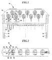
- FIG. 1 is the surge protection magazine according to the invention 10 in a plan view for clarification with transparent Housing 12 shown. This is the staggered arrangement to recognize the individual surge arrester 14.
- an earth contact 16 is present, via which the energy in the Case that at one of the contacts of the (not shown) Establishment of telecommunications technology to which the shown overvoltage protection magazine 10 is placed there is too much voltage, is discharged to earth.
- the two earth contacts 16 have a contact slot 18, in which, for example, one leg of each metal carrier system is introduced such that the Earth contact 16 electrically conductive with the carrier system connected, and electrical energy through that Carrier system can be derived from Earth.
- tapping contacts 20 At the back of the surge protection magazine 10, which is 1 located below and during of use to establish the Telecommunications technology is directed to extend from the surge protection magazine 10 a plurality of tapping contacts 20.
- Each of these tapping contacts 20 is on one Tap electrically conductive with the two each other assigned contacts of the establishment of the Telecommunications technology connected.
- tapping contact 20th trained clamping slot At his other, according to 1 is in an upper in the tapping contact 20th trained clamping slot one leg of each Surge arrester 14 introduced so that it immediately is electrically conductively connected to the tapping contact 20, what follows with reference to FIGS. 2 to 4 in more detail is explained.
- Fig. 1 In the top view of Fig. 1 it can only be seen that the middle leg of the surge arrester 14 extends into a respective contact slot 24, which in different heights of a common earth rail 26 are trained. Because if that on the Surge arrester 14 applied voltage a certain Exceeds the value, the surge arrester 14 trips and conducts the electrical energy over its respective middle leg 22 on the earth rail 26, which on not illustrated manner with both earth contacts 16 connected is. Otherwise, it is in each case the surge arrester 14 attached bracket 28 by one usual fail-safe device.
- the novel, staggered and therefore particularly space-saving arrangement of the Surge arrester 14 in the surge protection magazine 10 clear.
- the surge arrester 14 in which the center points or cylinder axes, i.e. according to the 1 the respective upper end of the shown Leg 22, located on a line, the width of the Surge protection magazine 10 by the sum of Diameter of the surge arrester 14 limited. Because about it also the individual surge arresters 14 from each other must be separated, and between these, if necessary, partitions are to be trained, the width of the Surge protection magazine 10 not below a certain Value can be decreased.
- the legs are between them arranged surge arrester 14 on the front Level and the tab extending to the leg 22 the earth rail 26.
- the Surge arresters 14 are from the rest Front of the housing, which is in accordance with the representation of Fig. 1 located above, can be used, the one on the front Level surge arrester 14 easily are removable.
- Those on the back level Surge arrester 14 can be seen in that with the lid open on both the top and the Underside exposed, which according to a preferred Embodiment of the invention by a U-shaped lid can be achieved.
- Surge protection magazine applicable measure are also the Surge arrester 14, which is at the rear level are graspable from above and below, so that they at least can be pulled out a little bit to the front, and then with the appropriate dimensioning of her legs and the Contact slots can be removed up or down.
- the removal of the surge arrester 14 at the rear level conceivable that at least at first one of the neighboring ones arranged in front Surge arrester 14 is removed.
- the single ones Legs of surge arrester 14 are unnecessary a circuit board electrically conductive with the earth rail 26 and the tapping contacts 20, which is what from FIG. 2 is clear, can be designed particularly simple.
- Fig. 2 shows the overvoltage protection magazine 10 from the Front with open lid, the Clarity because of only the front Surge arrester 14 are shown. How to get out of the Representation of Fig. 2 in connection with Fig. 1 results are these are largely cylindrical and point next to the in the middle extending legs 22 each lateral Legs 30 on. These legs 30 extend what from 3 and 4 becomes even clearer, in a respective Contact slot of a tapping contact 20.
- the individual Tapping contacts on the one hand have a section 32 which extends from the rear of the housing, as in Fig. 1 is recognizable. All sections 32 are what from Fig. 2 shows on a center line 34 with respect to Height of the surge protection magazine 10.
- FIGS. 3 and 4 are one Cross-sectional views through the described Surge protection magazine 10 shown at a point where one committed to the back level Surge arrester 14 is located.
- This "back" level is defined as being closer to the tapping sections 32 of the tapping contacts 20, which is in the (not shown) Facilitate the establishment of telecommunications technology the surge protector magazine 10 in use is plugged on. It is in the attached state otherwise in a compared to the orientation of Fig. 3 and 4 orientation rotated by 90 °.
- the overvoltage protection magazine 10 in FIGS. 3 and 4 as also shown standing in Fig. 1, so that the "rear" Level appears as the lower level.
- the tapping contact 20 exists from the narrow, strip-shaped described Tapping section 32 that extends to the rear of the housing enough.
- a web 38 is formed in this area to the section 36 with the insertion of the leg 30 serving contact slot 40 extends.
- the sheet level is between the tapping section 32 and the contact section 36, as can be seen in Fig. 2, bent so that the Contact section 36 to the drawing plane of FIGS. 3 and 4 runs inclined.
- the tapping contact 20 is special simply trained, so that no more besides Bends are required, but that the contact slot 40 by two flat, largely strip-shaped Contact leg 42 is defined, which lie in one plane and without problems when punching the tapping contact 20 can be trained.
- the leg 30 of the surge arrester 14 is parallel to the contact legs 42 inserted into the contact slot 40, wherein the insertion movement by guides, not shown, the formed in the housing of the surge protection magazine 10 are supported. Consequently, the structure of the Surge protection magazine 10 according to the invention in particular simply because it connects the legs 30 with the Tapping contacts 20 no circuit board and none complicated bends of the tapping contact 20 required are.
- the middle leg 22 is also shown in FIG. 3 to recognize the surge arrester 14, which in the Earth rail 26 extending perpendicular to the plane of the drawing is introduced.
- the two contact legs 42 together the shape of a U train that over a comparatively narrow Connecting web 44 is connected to the web 38. by virtue of that formed by the narrow connecting web 44
- the narrow region of the contact area 36 can possibly be tilted a little be what allows the compensation of manufacturing tolerances.
- such a measure with side narrow points 46 also for the tapping contacts 20 provided that the contacting of the legs 30 on the serve front level arranged surge arrester 14.
- the individual tapping contact 20 is the same as that in FIG. 3 Tapping contact 20 shown essentially coincident designed with the exception that the connecting web 44th between the contact area 36 and that to the Tapping section 32 leading web 38 is longer.
- the contact section 36 is located on a further ahead, i.e. as shown in FIG. 4 higher Level so that the legs 30 of the on the front level arranged surge arrester 14, which differs from the do not differentiate rear surge arresters 14, can be contacted directly electrically conductive.
- FIG. 5 is a second embodiment of the Surge protection magazine 10 according to the invention in one Top view shown using the same principles Find use as in the previously described Execution is the case.
- the staggered arrangement in this embodiment achieved that the surge arrester alternately from the The top and bottom of the housing 12 can be used.
- the embodiment of FIG. 5 also points to the a ground contact 16 on both side edges, the both also with a contact slot at their upper end are provided in the one with respect to their sheet metal level 90 ° rotated earth rail 26 can be inserted with its ends.
- the earth rail 26 is one standing perpendicular to the drawing plane of FIG. 5
- Metal strip at both ends towards the Earth contacts 16 is bent.
- respective intermediate contacts 48 clamped over clamping slots, which is clearer from Fig. 8.
- the intermediate contacts 48 have ends located 26 away respective contact slots on the introduction of middle, that is, the derivative legs of the Surge arrester 14 serve.
- Tapping contacts one from the back of the housing to the Establishing telecommunications technology Tapping section 32, and are at their respective other Provide the end with a contact area that matches the Contact area 36 of those shown in FIGS. 3 and 4 Tapping contacts 20 matches and the introduction of Legs 30 in a respective contact slot in one Alignment parallel to this serves.
- FIG. 6 is a partial section in the front view recognize in which staggered arrangement the individual surge arrester 14, which alternate in the direction of the extension of their legs 30 from the upper or the bottom can be used.
- the legs of those inserted from the bottom Surge arrester towards the top In the at the areas adjacent to the top are the Contact areas of the tapping and intermediate contacts. this applies accordingly vice versa for those from the top used surge arrester 14, the legs together with the contacting sections of the Contacts at the bottom in the area between two neighboring ones, inserted from the bottom Surge arresters 14 are located.
- surge arrester 14 with a fail-safe device be used.
- FIGS. 7 and 8 The electrical connection shown in FIGS. 7 and 8 the legs 30 and 22 with the tapping contacts 20 and Intermediate contacts 48 additionally simplifies the construction of the Surge protection magazine 10.
- Fig. 7 for one of the underside of surge arrester 14 used can be seen, the tapping contact 20 to that in FIG. 4 shown tapping contact 20 of the first embodiment similarly designed, the contact area 36 on the Connecting web 44 in an orientation rotated by 90 ° is trained. At the transition between the contact area 36 and the connecting web 44 are again narrow points 46 to be able to tilt through the possibility of Compensate manufacturing tolerances.
- the introduction of the Leg 36 takes place in the respective tapping contact 20 immediately and without the need for intermediate contacts or a circuit board.
- the guided tours that support this are formed in an intermediate wall of the housing.
- the single tapping contact 20 can, as in Fig. 7 in connection 5 shows, punched out as a simple component and in the area of the connecting web 44 with the only one required bend.
- the intermediate contact 48 has on its 8 lower end of a contact area, which too the previously described contact areas 36 of the Tapping contacts 20 is similar.
- the end is the intermediate contact, which is also simply bent 48 (cf. FIG. 5) provided with a further contact slot, via which it is clamped to the earth rail 26. This too Connection is thus carried out immediately and requires no circuit board or the like.
- 7 and 8 is finally the two-part construction of the housing housing halves that can be snapped onto one another.
Landscapes
- Emergency Protection Circuit Devices (AREA)
Description
Die Erfindung betrifft ein Überspannungsschutzmagazin für
eine Einrichtung der Telekommunikationstechnik gemäß dem
Oberbegriff der Ansprüche 1 und 4.The invention relates to a surge protection magazine for
a facility of telecommunications technology according to the
The preamble of
In der Telekommunikationstechnik werden verbreitet Überspannungsschutzmagazine verwendet, die auf Einrichtungen, beispielsweise Anschlußleisten, der Telekommunikationstechnik aufgesetzt werden, um elektronische Bauteile oder Geräte, die an die genannte Einrichtung angeschlossen sind, vor Überspannungen zu schützen. Übliche Schutzmagazine weisen im Gegensatz zu einzelnen Doppeladern zugeordneten Schutzsteckern mehrere Überspannungsableiter auf und sind darüber hinaus so gestaltet, daß sie derart auf die zumeist leistenförmigen Einrichtungen der Telekommunikationstechnik aufgesteckt werden können, daß von sämtlichen Kontakten einer derartigen Einrichtung jeweils die anliegende Spannung abgegriffen wird. Zu diesem Zweck weisen bekannte Überspannungsschutzmagazine mehrere Kontakte auf, die sich mit einem Abschnitt von der Gehäuserückseite des Überspannungsschutzmagazins, also derjenigen Seite, die zu der Anschlußeinrichtung gerichtet ist, erstrecken und im angebrachten Zustand die Kontakte der Einrichtung der Telekommunikationstechnik abgreifen. In telecommunications technology are spread Surge protection magazines used on facilities for example terminal strips, telecommunications technology be placed around electronic components or devices that are connected to the facility mentioned Protect surges. Usual protection magazines point in Contrast with individual twisted pair Protective plugs on and are multiple surge arresters moreover designed in such a way that most of the time strip-shaped telecommunications equipment can be plugged in that one of all contacts such device the applied voltage is tapped. Known for this purpose Surge protection magazines have multiple contacts that are with a section from the back of the case Surge protection magazine, that is, the side facing the connection device is directed, extend and in attached condition the contacts of the establishment of the Tap telecommunications technology.
An diese Abgreifkontakte sind Überspannungsableiter, die in das Überspannungsschutzmagazin einsetzbar sind, elektrisch leitend angeschlossen, so dass eine an dem Abgreifkontakt des Überspannungsschutzmagazins anliegende Überspannung auch an dem einzelnen Überspannungsableiter anliegt. Bei Überschreiten einer bestimmten Spannung löst der Überspannungsableiter aus und leitet die elektrische Energie auf Erde ab. Zu diesem Zweck besitzen die beschriebenen Überspannungsschutzmagazine einen Erdkontakt, der aus dem Gehäuse herausreicht und mit Erde verbunden ist.Surge arresters connected to these tapping contacts the surge protection magazine can be used, electrically conductively connected, so that one at the tapping contact of the Overvoltage protection magazine also applied to overvoltage applied to the individual surge arrester. at If a certain voltage is exceeded, the Surge arrester and conducts the electrical energy down to earth. For this purpose the described Surge protection magazines have an earth contact that comes from the Housing extends and is connected to earth.
Ein Überspannungsschutzmagazin gemäß dem Oberbegriff der
Ansprüche 1 und 4 ist aus der EP 0 405 337 A2 bekannt.
Mehrere bedrahtete Überspannungsableiter sind von der
Vorderseite eines Überspannungsschutzmagazins her derart
einsteckbar, dass sich ihre Beinchen weitgehend parallel in
einen Kontaktschlitz erstrecken, der durch zwei weitgehend in
einer Ebene liegende Kontaktschenkel definiert ist. Sämtliche
Überspannungsschutzableiter sind nebeneinander angeordnet, so
dass die Baugröße unweigerlich durch die Summe der
Durchmesser der einzelnen Überspannungsableiter definiert
ist.A surge protection magazine according to the generic term of
Aus der EP 0 446 433 A2 ist eine Schutzbaugruppe bekannt, bei
der von der Oberseite her mehrere Überspannungsableiter in
zwei Reihen einsetzbar sind. Die Ableiter werden in einer
Richtung senkrecht zu der Erstreckung ihrer Beinchen
eingesetzt, und ihre Beinchen werden weitgehend senkrecht in
einen Kontaktschlitz eingedrückt. Für diese Ausgestaltung
müssen die Kontakte abgewickelt ausgebildet werden, was den
Herstellungsaufwand erhöht. Ferner weist eine derartige
Schutzbaugruppe eine vergleichsweise große Tiefenerstreckung
auf, da die Ableiter in zwei Reihen angeordnet sind und sich
die Tiefe maßgeblich durch den zweifachen Durchmesser der
Ableiter sowie die zweifache Länge der sich von dem Ableiter
erstreckenden Beinchen ergibt.A protective assembly is known from
Ein weiteres Überspannungsschutzmagazin ist aus der DE 30 14 796 C3 bekannt. Hierbei sind Überspannungsableiter in einer Anzahl, die der Zahl der an die zugeordnete Anschlusseinrichtung anschließbaren Doppeladern entspricht, von einer Gehäusevorderseite her nebeneinander in das Überspannungsschutzmagazin eingesetzt. Bei den Überspannungsableitern handelt es sich um bedrahtete Bauteile, die sogenannte Beinchen aufweisen, die mit den Abgreifkontakten des Überspannungsschutzmagazins unmittelbar elektrisch leitend verbunden sind. Zu diesem Zweck sind sowohl die Abgreifkontakte als auch der Erdkontakt an denjenigen Abschnitten, an denen sie die Beinchen der Überspannungsableiter kontaktieren, in eine U-Form gebogen, so dass die Beinchen der Überspannungsableiter an den Innenflächen der U-förmig ausgebildeten Bereiche der Abgreifkontakte elektrisch kontaktiert werden.Another surge protection magazine is out of the DE 30 14 796 C3 known. Here are surge arresters in a number equal to the number assigned to the Connection device corresponds to connectable double cores, from a front of the housing side by side into the Surge protection magazine used. Both Surge arresters are wired Components that have so-called legs, which with the Tapping contacts of the surge protection magazine immediately are electrically connected. For this purpose both the tapping contacts and the earth contact the sections where they have the legs of the Contact surge arrester, bent into a U shape, so that the legs of the surge arrester on the Inner surfaces of the U-shaped areas of the Tapping contacts are electrically contacted.
Die Gestalt sowohl der Abgreifkontakte als auch des Erdkontakts ist vergleichsweise kompliziert. Dies liegt daran, dass die Biegekanten für die Ausbildung des U-förmigen Bereichs nicht parallel zu denjenigen Biegekanten sind, die im weiteren Verlauf der Kontakte zur Ausbildung derjenigen Abschnitte, mit denen die Kontakte der Anschlusseinrichtung abgegriffen werden, vorgesehen sind. Somit gestaltet sich die Herstellung der Abgreif- und Erdkontakte eines derartigen Überspannungsschutzmagazins aufgrund der Notwendigkeit von Biegevorgängen um zueinander nicht parallele Biegekanten aufwendig.The shape of both the tapping contacts and the Earth contact is comparatively complicated. This is because remember that the bending edges for the formation of the U-shaped Range are not parallel to those bending edges that in the further course of contacts for the training of those Sections with which the contacts of the connection device are tapped, are provided. Thus the Production of the tapping and earth contacts of such Surge protection magazine due to the need of Bending processes around bending edges that are not parallel to each other consuming.
Ferner ist bei diesem bekannten Überspannungsschutzmagazin die Baugröße des Magazins notwendigerweise durch den Platzbedarf der nebeneinander eingesetzten Überspannungsableiter bestimmt. Mit anderen Worten kann die Breite eines derartigen Überspannungsschutzmagazins nicht geringer ausgebildet werden, als das Maß der in der erforderlichen Anzahl nebeneinander angeordneten Überspannungsableiter. Somit schränkt dieses bekannte Überspannungsschutzmagazin aufgrund der festgelegten Baugröße die Möglichkeit ein, den Platzbedarf für die Einrichtungen der Telekommunikationstechnik einschließlich der darauf aufgesetzten Überspannungsschutzmagazine zu verringern.Furthermore, this known surge protection magazine the size of the magazine necessarily by the Space required for the side by side Surge arrester determined. In other words, it can Width of such a surge protection magazine is not be formed less than the degree of in the required number arranged side by side Surge arresters. This limits this known Surge protection magazine due to the specified size the possibility of a space requirement for the facilities of telecommunications technology including those on it to put on overvoltage protection magazines.
Aus der DE 31 13 759 C2 ist eine Überspannungsableitervorrichtung für Trennleisten bekannt, bei der mehrere bedrahtete Überspannungsableiter von der Gehäuseoberseite her einsetzbar sind, wobei die Beinchen der Überspannungsableiter nur mittelbar, nämlich über sogenannte Klemmaufnehmer, elektrisch leitend mit den Abgreifkontakten verbunden sind. Aufgrund dieser Tatsache und infolge der vergleichsweise umfangreichen Baugröße dieses bekannten Magazins ist auch dieses verbesserungsbedürftig.From DE 31 13 759 C2 is one Surge arrester device for isolating strips known where several wired surge arresters from the The top of the housing can be used, the legs of the Surge arrester only indirectly, namely via so-called Clamp sensor, electrically conductive with the tapping contacts are connected. Because of this and as a result of comparatively large size of this known Magazine is also in need of improvement.
Ein Schutzstecker für Anschluß- und Trennleisten, der mehrere
nicht bedrahtete Überspannungsableiter aufweist, ist aus der
DE 42 25 484 C1 bekannt. Die nicht bedrahteten, weitgehend
zylinderförmigen Überspannungsableiter werden durch einen
Kontaktkäfig kontaktiert. Dieser ist jedoch notwendigerweise
kompliziert gestaltet und eignet sich darüber hinaus nicht
für die Kontaktierung von bedrahteten Überspannungsableitern,
die gattungsgemäß zu verwenden sind. A protective plug for connection and isolating strips, the several
has unwired surge arrester is from the
Dies gilt in gleicher Weise für das aus der DE 34 30 922 A1 bekannte Magazin, das eine Leiterplatte aufweist, durch deren Kontaktbahnen die Kontakte der Anschlußeinrichtung abgegriffen werden. Schon aufgrund der Notwendigkeit einer Leiterplatte ist dieses bekannte Magazin in wirtschaftlicher Hinsicht nachteilig.This applies in the same way to that from DE 34 30 922 A1 known magazine, which has a circuit board, by the Contact tracks the contacts of the connection device be tapped. Simply because of the need for one Printed circuit board is this well-known magazine in economical Disadvantageous.
Der Erfindung liegt die Aufgabe zugrunde, ein gattungsgemäßes Überspannungsschutzmagazin zu schaffen, das einen einfachen Aufbau aufweist, so daß es mit geringem Aufwand hergestellt werden kann, und das darüber hinaus besonders klein gestaltet werden kann.The invention has for its object a generic Surge protection magazine to create a simple Has structure so that it is manufactured with little effort can be, and also designed particularly small can be.
Die Lösung dieser Aufgabe erfolgt zum einen durch das im Patentanspruch 1 beschriebene Überspannungsschutzmagazin.This task is solved on the one hand by the Claim 1 surge protection magazine.
Demzufolge sind die Abgreifkontakte, mit denen die Beinchen der Überspannungsableiter unmittelbar elektrisch leitend verbunden sind, so gestaltet, daß sie einen Kontaktschlitz aufweisen, der durch zwei weitgehend in einer Ebene liegende Kontaktschenkel definiert ist. Hierdurch können für die Abgreifkontakte komplizierte Biegeoperationen vermieden werden, da der Kontaktschlitz nicht durch Biegung eines streifenförmigen Abschnitts in eine U-Form ausgebildet wird, sondern durch Ausstanzen des Kontaktschlitzes in dem streifenförmigen Kontakt. Somit definieren zwei weitgehend in einer Ebene liegende Blechstreifen, welche die Kontaktschenkel darstellen, zwischen sich den Kontaktschlitz. Durch die unmittelbare Kontaktierung der Beinchen der Überspannungsableiter zwischen den beiden Kontaktschenkeln wird in vorteilhafter Weise eine Leiterplatte vermieden, so daß der Herstellungsaufwand für das erfindungsgemäße Überspannungsschutzmagazin gering gehalten werden kann. Darüber hinaus lassen sich die in der beschriebenen Weise gestalteten Abgreifkontakte besonders leicht durch einfache Stanz- und Biegevorgänge, die insbesondere um zueinander parallele Kanten erfolgen können, herstellen.Accordingly, the tapping contacts with which the legs the surge arrester is directly electrically conductive are connected so that they have a contact slot have, by two largely lying in one plane Contact leg is defined. This allows for Tapping contacts avoided complicated bending operations because the contact slot is not made by bending a strip-shaped section is formed into a U-shape, but by punching out the contact slot in the striped contact. Thus, two largely define in metal strips lying on one level, which the Represent contact legs, the contact slot between them. Through the direct contact of the legs of the Surge arrester between the two contact legs a printed circuit board is advantageously avoided, so that the manufacturing cost for the invention Surge protection magazine can be kept low. They can also be described in the manner described designed tapping contacts particularly easy through simple Stamping and bending processes, in particular to each other parallel edges can be made.
Bei der ersten Ausführungsform der Erfindung sind die Überspannungsableiter von der Gehäusevorderseite her in Richtung ihrer Beinchen derart in das Magazin einsetzbar, dass sich die Beinchen in einer Richtung weitgehend parallel zu dem Kontaktschlitz in diesen erstrecken. Eine derartige Kontaktierung der Beinchen bedrahteter Überspannungsableiter stellt für ein Überspannungsableitermagazin eine neuartige Maßnahme dar. Wie nachfolgend noch genauer erläutert wird, kann hierdurch der gesamte Aufbau des Überspannungsschutzmagazins erheblich vereinfacht werden.In the first embodiment of the invention Surge arrester from the front of the housing Can be inserted into the magazine in the direction of her legs, that the legs are largely parallel in one direction extend to the contact slot in this. Such Contacting the legs of wired surge arresters provides a new type for a surge arrester magazine Measure. As will be explained in more detail below, can the entire structure of the Surge protection magazine can be significantly simplified.
Die beschriebene Einführrichtung von der Gehäusevorderseite her ermöglicht nämlich bei der vorliegenden Ausführungsform ferner, dass sich die Überspannungsableiter im eingesetzten Zustand alternierend auf zumindest zwei unterschiedlichen Niveaus hinsichtlich der Tiefenerstreckung des Überspannungsschutzmagazins befinden. Mit anderen Worten sind die Überspannungsableiter von der Oberseite aus betrachtet zueinander versetzt angeordnet. Bei dieser Betrachtungsweise sind die weitgehend zylinderförmigen Überspannungsableiter als Kreise zu erkennen. Bei dem gattungsgemäßen herkömmlichen Überspannungsschutzmagazin liegen sämtliche Mittelpunkte dieser Kreise auf einer Linie, so dass der Platzbedarf durch die Summe der Durchmesser bestimmt ist und nicht weiter reduziert werden kann.The described direction of insertion from the front of the housing This is because in the present embodiment also that the surge arrester used State alternating on at least two different ones Levels related to the depth of the Surge protection magazine are located. In other words the surge arresters viewed from the top staggered. With this approach are the largely cylindrical surge arresters recognizable as circles. In the generic conventional Surge protection magazine is all center of these circles on a line so that the space required by the sum of the diameters is determined and not further can be reduced.
Erfindungsgemäß sind die einzelnen Überspannungsableiter von der Oberseite aus betrachtet derart zueinander versetzt angeordnet, dass sich ihre Mittelpunkte auf einer Zickzacklinie befinden. Hierdurch kann die Breite des Magazins verringert werden, so dass in Verbindung mit entsprechend gestalteten Anschlusseinrichtungen der Telekommunikationstechnik eine erhebliche Platzeinsparung ermöglicht wird. Zu diesem Zweck erstrecken sich die Abgreifkontakte, welche die Kontakte der Anschlußeinrichtungen abgreifen, alternierend unterschiedlich weit in Richtung der Vorderseite des Überspannungsschutzmagazins, so daß die von der Vorderseite her unterschiedlich weit eingeführten Überspannungsableiter kontaktiert werden können. In dieser Ausführungsform des erfindungsgemäßen Überspannungsschutzmagazins wird somit bei einem einfachen Aufbau für eine platzsparende Gestaltung des Magazins gesorgt.According to the invention, the individual surge arresters are from viewed from the top so offset from each other arranged that their centers are on a Zigzag line. This allows the width of the Magazine are reduced, so in conjunction with correspondingly designed connection facilities of Telecommunication technology a considerable space saving is made possible. To this end, the Tapping contacts, which are the contacts of the Tap connection devices, alternately different far towards the front of the Surge protection magazine, so that from the front Hereby, surge arresters are introduced at different distances can be contacted. In this embodiment of the Surge protection magazine according to the invention is thus at a simple structure for a space-saving design of the Magazine.
Bevorzugte Weiterbildungen dieser ersten Ausführungsform der Erfindung sind in den weiteren Ansprüchen beschrieben.Preferred developments of this first embodiment of the Invention are described in the further claims.
Bevorzugt ist die Vorderseite des Gehäuses durch einen abnehmbaren Deckel verschließbar, so daß das vollständig bestückte Magazin einen abgeschlossenen Eindruck erweckt, und die eingesetzten Überspannungsableiter sowie die in dem Magazin untergebrachten Kontakte und Ableiter vor Verschmutzungen geschützt sind.The front of the housing is preferred by a removable lid can be closed so that it is completely stocked magazine gives a complete impression, and the surge arresters used and those in the Magazine housed contacts and arresters Soiling is protected.
Ein besonders einfacher Aufbau ergibt sich ferner, wenn das Überspannungsschutzmagazin eine Erdschiene aufweist, mit der im eingesetzten Zustand jeweils ein Kontakt der Überspannungsableiter unmittelbar elektrisch leitend verbunden ist. Mit anderen Worten wird der Grundgedanke einer unmittelbar elektrisch leitenden Verbindung der Beinchen der Überspannungsableiter mit den Abgreifkontakten auch auf den Erdkontakt in Form einer Erdschiene übertragen, so daß auch in diesen Bereich jegliche Zwischenkontakte oder im Stand der Technik erforderliche Leiterplatten vermieden werden können.A particularly simple structure also results if the Surge protection magazine has an earth rail with which one contact of the Surge arrester directly conductive connected is. In other words, the basic idea becomes one direct electrically conductive connection of the legs of the Surge arrester with the tapping contacts also on the Earth contact transferred in the form of an earth rail, so that too in this area any intermediate contacts or in the state of the Technology required circuit boards can be avoided.
Die Lösung der der Erfindung zugrundeliegenden Aufgabe erfolgt zum anderen durch das Überspannungsschutzmagazin gemäß dem Anspruch 4.The solution to the problem on which the invention is based on the other hand is carried out by the surge protection magazine according to claim 4.
Auch bei dieser Ausführungsform der Erfindung wird die Baugröße des Überspannungsschutzmagazins in vorteilhafter Weise gegenüber den im Stand der Technik bekannten Magazinen dadurch verringert, daß die Überspannungsableiter zueinander versetzt in das Magazin einsetzbar sind. Bei dieser Ausführungsform wird der Grundgedanke der Erfindung dadurch realisiert, daß die Überspannungsableiter wechselweise von der Ober- und Unterseite her in das Magazin einsetzbar sind, wobei sich die Beinchen im eingesetzten Zustand jeweils zur Unter- bzw. Oberseite hin erstrecken. Somit ist die Versetzung der Überspannungsableiter bei dieser Ausführungsform von der Vorderseite aus erkennbar. Bei dieser Betrachtungsrichtung erscheinen die Überspannungsableiter, die von oben bzw. unten in Richtung ihrer Beinchen einsetzbar sind, als Kreise. Ähnlich wie bei der vorangehend beschriebenen Ausführungsform, lediglich um 90° gedreht, sind die von der Vorderseite aus betrachtet kreisförmigen Überspannungsableiter zueinander versetzt, mit ihren Mittelpunkten auf einer Zickzacklinie angeordnet. Die Beinchen der von der Oberseite her eingesetzten Überspannungsableiter erstrecken sich dabei zwischen zwei zueinander benachbart von der Unterseite her eingesetzte Überspannungsableiter.In this embodiment of the invention, too Size of the surge protection magazine in an advantageous Way compared to the magazines known in the prior art thereby reduced that the surge arrester to each other can be inserted offset in the magazine. At this Embodiment becomes the basic idea of the invention realized that the surge arrester alternately from the top and bottom can be inserted into the magazine, the legs in the inserted state to each Extend the bottom or top. So that is Relocation of the surge arrester at this Embodiment recognizable from the front. At this The surge arresters appear in the viewing direction, which can be used from above or below in the direction of their legs are as circles. Similar to the previous one described embodiment, only rotated by 90 ° the circular viewed from the front Surge arresters offset from one another, with their Center points arranged on a zigzag line. The Legs of those inserted from the top Surge arresters extend between two used adjacent to each other from the bottom Surge arresters.
Auch bei dieser Ausführungsform der Erfindung kann durch die nachfolgend beschriebenen bevorzugten Maßnahmen die Notwendigkeit einer Leiterplatte oder von Zwischenkontakten vermieden werden. Darüber hinaus läßt sich auch bei dieser Ausführungsform in vorteilhafter Weise die Baugröße verglichen mit dem Stand der Technik erheblich reduzieren, indem durch die beschriebene Versetzung die Breite des Überspannungsschutzmagazins gegenüber der Summe der Durchmesser der eingesetzten Überspannungsableiter reduziert werden kann.In this embodiment of the invention can also by preferred measures described below The need for a printed circuit board or intermediate contacts be avoided. In addition, this can also Embodiment advantageously the size significantly reduce compared to the prior art, by the width of the Surge protection magazine compared to the sum of the Diameter of the surge arrester used reduced can be.
Bevorzugt ist bei der zuletzt beschriebenen Ausführungsform der Erfindung der Erdkontakt des Magazins elektrisch leitend mit einer streifenförmigen Erdschiene verbunden, deren Blechebene unter einem Winkel von etwa 90° zur Blechebene des Erdkontakts verläuft. Hierdurch kann die Erdschiene in einfacher Weise durch Klemmung mit dem zumindest einen Erdkontakt verbunden werden.Is preferred in the last described embodiment the invention the ground contact of the magazine electrically conductive connected to a strip-shaped earth rail, the Sheet metal plane at an angle of approximately 90 ° to the sheet metal plane of the Earth contact runs. This allows the earth rail in simply by clamping with the at least one Earth contact.
Als besonders vorteilhaft hat sich in diesem Fall die Verwendung von Zwischenkontakten zur Verbindung mit der Erdschiene erwiesen.In this case, the Use of intermediate contacts to connect to the Earth rail proven.
Auch bei der zuletzt beschriebenen Ausführungsform wird für die Abgreifkontakte und/oder die Zwischenkontakte bevorzugt, daß diese mit Kontaktschlitzen versehen sind, die durch zwei streifenförmige, in einer Ebene liegenden Kontaktschenkel begrenzt sind. Die in dieser Weise gestalteten Kontakte können durch Stanzen und eine einfache Biegeoperation hergestellt werden und gestatten eine zuverlässige, unmittelbar elektrisch leitende Verbindung der Beinchen der Überspannungsableiter mit den Kontakten.Also in the last described embodiment, for preferred the tapping contacts and / or the intermediate contacts, that these are provided with contact slots which are separated by two strip-shaped contact legs lying in one plane are limited. The contacts designed in this way can be done by punching and a simple bending operation are manufactured and allow a reliable, direct electrically conductive connection of the legs of the Surge arrester with the contacts.
Es wird, wie dies bei der ersten Ausführungsform der Fall ist, ferner bevorzugt, daß die Beinchen der Überspannungsableiter parallel zu den Kontaktschlitzen in diese einführbar sind. Diese in der Technik für Überspannungsschutzmagazine bislang nicht bekannte Orientierung der Beinchen zu den Kontaktschlitzen ermöglicht, was aus der nachfolgenden Beschreibung der bevorzugten Ausführungsbeispiele anhand der Zeichnungen noch deutlicher wird, daß insgesamt der Aufbau des Überspannungsschutzmagazins vereinfacht werden kann.It will, like the first embodiment is further preferred that the legs of the Surge arrester parallel to the contact slots in these are insertable. This in technology for Surge protection magazines not yet known Allows orientation of the legs to the contact slots, what from the following description of the preferred Embodiments with reference to the drawings more clearly is that overall the structure of the Surge protection magazine can be simplified.
Für den Ausgleich von Toleranzen an den mit den beschriebenen Kontaktschlitzen versehenen Kontakten bietet es Vorteile, wenn an zumindest einem Kontaktschenkel benachbart eine Engstelle ausgebildet ist. Hierdurch kann der Bereich des Kontaktschlitzes insgesamt ein wenig elastisch kippen, so daß Fertigungstoleranzen ausgeglichen werden können, und stets eine sicher elektrisch leitende Kontaktierung der Beinchen ermöglicht wird. To compensate for tolerances on those described with Contact slots provided contacts offers advantages, if one is adjacent to at least one contact leg Constriction is formed. This allows the area of Tilt the contact slot a little bit elastically so that Manufacturing tolerances can be compensated, and always safe electrically conductive contacting of the legs is made possible.
Wie bereits erwähnt, bietet es für sämtliche Ausführungsformen der Erfindung erhebliche Vorteile, wenn die verwendeten Abgreif- und/oder Zwischenkontakte als Blechelemente ausgebildet sind, die mit zumindest einer Biegung parallel zur Blechebene versehen sind. Hierdurch können die Kontakte mit geringem Aufwand in die Form gebracht werden, die für die Kontaktierung sowohl der abzugreifenden Kontakte an der Anschlußeinrichtung als auch der Beinchen der Überspannungableiter erforderlich ist. Im Fall einer mehrfachen Biegung können sämtliche Biegekanten zueinander parallel ausgerichtet werden, was die Herstellung vereinfacht.As already mentioned, it offers for everyone Embodiments of the invention have significant advantages when the used tapping and / or intermediate contacts as Sheet metal elements are formed with at least one Bending are provided parallel to the sheet plane. hereby can get the contacts into shape with little effort be used for contacting both the Contacts on the connection device and the legs of the Surge arrester is required. In the case of one Multiple bending can all bending edges to each other be aligned in parallel with what the manufacture simplified.
Schließlich bietet es für die sichere und positionsgenaue Einführung der Überspannungsableiter Vorteile, wenn in dem Gehäuse des Überspannungsschutzmagazins Führungen für die Beinchen der Überspannungsableiter vorgesehen sind. Hierdurch wird insbesondere bei der beschriebenen Ausrichtung der Beinchen parallel zu einem durch zwei streifenförmige Kontaktschenkel begrenzten Kontaktschlitz die korrekte Anordnung der Beinchen sichergestellt.After all, it provides for safe and positionally accurate Introduction of surge arrester advantages if in the Housing of the surge protection magazine guides for the Legs of surge arresters are provided. hereby is particularly in the described orientation of the Legs parallel to one by two stripe-shaped Contact leg limited contact slot the correct one Arrangement of the legs ensured.
Nachfolgend werden einige beispielhaft in den Figuren dargestellte Ausführungsformen der Erfindungen näher erläutert. Es zeigen:
- Fig. 1
- eine Draufsicht des erfindungsgemäßen Überspannungsschutzmagazins in einer ersten Ausführungsform;
- Fig. 2
- eine Vorderansicht des in Fig. 1 gezeigten Überspannungsschutzmagazins;
- Fig. 3
- eine Querschnittsansicht des in den Fig. 1 und 2 gezeigten Überspannungsschutzmagazins an einer Stelle mit einem tiefer eingesetzten Überspannungsableiter;
- Fig. 4
- eine Querschnittsansicht des in den Fig. 1 und 2 gezeigten Überspannungsschutzmagazins an einer Stelle mit einem höher eingesetzten Überspannungsableiter;
- Fig. 5
- eine Draufsicht des erfindungsgemäßen Überspannungsschutzmagazins in einer zweiten Ausführungsform;
- Fig. 6
- eine Vorderansicht des in Fig. 5 gezeigten Überspannungsschutzmagazins mit Teilschnitt;
- Fig. 7
- eine Querschnittsansicht des in den Fig. 5 und 6 gezeigten Überspannungsschutzmagazins an einer Stelle mit einem von der Unterseite her eingesetzten Überspannungsableiter; und
- Fig. 8
- eine Querschnittsansicht des in den Fig. 5 und 6 gezeigten Überspannungsschutzmagazins an einer Stelle mit einem von der Oberseite her eingesetzten Überspannungsableiter.
- Fig. 1
- a plan view of the surge protection magazine according to the invention in a first embodiment;
- Fig. 2
- a front view of the surge protection magazine shown in Fig. 1;
- Fig. 3
- a cross-sectional view of the surge protection magazine shown in Figures 1 and 2 at one point with a deeper surge arrester;
- Fig. 4
- a cross-sectional view of the surge protection magazine shown in Figures 1 and 2 at a location with a surge arrester used higher.
- Fig. 5
- a plan view of the surge protection magazine according to the invention in a second embodiment;
- Fig. 6
- a front view of the surge protection magazine shown in Figure 5 with partial section.
- Fig. 7
- a cross-sectional view of the surge protection magazine shown in Figures 5 and 6 at one point with a surge arrester inserted from the bottom. and
- Fig. 8
- a cross-sectional view of the surge protection magazine shown in FIGS. 5 and 6 at one point with a surge arrester inserted from the top.
In Fig. 1 ist das erfindungsgemäße Überspannungsschutzmagazin
10 in einer Draufsicht zur Verdeutlichung mit transparentem
Gehäuse 12 dargestellt. Hierdurch ist die versetzte Anordnung
der einzelnen Überspannungsableiter 14 zu erkennen. In den
beiden seitlichen Randbereichen des Gehäuses 12 ist jeweils
ein Erdkontakt 16 vorhanden, über den die Energie in dem
Fall, daß an einem der Kontakte der (nicht dargestellten)
Einrichtung der Telekommunikationstechnik, auf die das
gezeigte Überspannungsschutzmagazin 10 aufgesetzt ist, eine
zu hohe Spannung anliegt, auf Erde abgeleitet wird. Zu diesem
Zweck weisen die beiden Erdkontakte 16 einen Kontaktschlitz
18 auf, in den beispielsweise jeweils ein Schenkel eines
metallenen Trägersystems derart eingeführt ist, daß der
Erdkontakt 16 elektrisch leitend mit dem Trägersystem
verbunden ist, und die elektrische Energie über das
Trägersystem auf Erde abgeleitet werden kann.1 is the surge protection magazine according to the
An der Rückseite des Überspannungsschutzmagazins 10, die sich
gemäß der Darstellung von Fig. 1 unten befindet und während
der Verwendung zu der Einrichtung der
Telekommunikationstechnik gerichtet ist, erstrecken sich von
dem Überspannungsschutzmagazin 10 mehrere Abgreifkontakte 20.
Ein jeder dieser Abgreifkontakte 20 ist an einer
Abgreifstelle elektrisch leitend mit den beiden einander
zugeordneten Kontakten der Einrichtung der
Telekommunikationstechnik verbunden. An seinem anderen, gemäß
Fig. 1 oberen Ende ist in einen in dem Abgreifkontakt 20
ausgebildeten Klemmschlitz jeweils ein Beinchen des
Überspannungsableiters 14 eingeführt, so daß es unmittelbar
elektrisch leitend mit dem Abgreifkontakt 20 verbunden ist,
was nachfolgend unter Bezugnahme auf die Fig. 2 bis 4 näher
erläutert wird.At the back of the
In der Draufsicht von Fig. 1 ist lediglich zu erkennen, daß
sich das jeweils mittlere Beinchen des Überspannungsableiters
14 in einen jeweiligen Kontaktschlitz 24 erstreckt, die in
verschiedenen Höhen einer gemeinsamen Erdschiene 26
ausgebildet sind. Wenn nämlich die an dem
Überspannungsableiter 14 anliegende Spannung einen bestimmten
Wert überschreitet, so löst der Überspannungsableiter 14 aus
und leitet die elektrische Energie über sein jeweiliges
mittleres Beinchen 22 auf die Erdschiene 26 ab, die auf nicht
dargestellte Art und Weise mit beiden Erdkontakten 16
verbunden ist. Im übrigen handelt es sich bei der jeweils um
den Überspannungsableiter 14 angebrachten Klammer 28 um eine
übliche Fail-safe-Einrichtung.In the top view of Fig. 1 it can only be seen that
the middle leg of the
Aus der Darstellung von Fig. 1 wird ferner die neuartige,
versetzte und deshalb besonders platzsparende Anordnung der
Überspannungsableiter 14 in dem Überspannungsschutzmagazin 10
deutlich. Wie ohne weiteres zu erkennen ist, ist bei einer
üblichen Anordnung der Überspannungsableiter 14, bei der sich
die Mittelpunkte oder Zylinderachsen, also gemäß der
Darstellung von Fig. 1 das jeweilige obere Ende des gezeigten
Beinchens 22, auf einer Linie befinden, die Breite des
Überspannungsschutzmagazins 10 durch die Summe der
Durchmesser der Überspannungsableiter 14 begrenzt. Da darüber
hinaus die einzelnen Überspannungsableiter 14 voneinander
getrennt werden müssen, und zwischen diesen ggf. Trennwände
auszubilden sind, kann die Breite des
Überspannungsschutzmagazins 10 nicht unter einen bestimmten
Wert verringert werden. Eine Verschmälerung wird
erfindungsgemäß jedoch dadurch ermöglicht, daß sich die
Überspannungsableiter 14 alternierend auf unterschiedlichen
Tiefenniveaus, d.h. auf einer unterschiedlichen Höhe gemäß
der Darstellung von Fig. 1, befinden. Hierdurch können die
Überspannungsableiter 14 in der Breitenrichtung gesehen näher
zusammengerückt werden. Ferner kann aufgrund des größeren
Abstandes zwischen den Überspannungsableitern 14 auf
Zwischenwände verzichtet werden, was sich auf die
erforderliche Baugröße ebenfalls vorteilhaft auswirkt.From the representation of Fig. 1, the novel,
staggered and therefore particularly space-saving arrangement of the
In dem Zwischenraum zwischen zwei Überspannungsableitern 14
auf dem hinteren, gemäß der Darstellung von Fig. 1 unteren
Niveau, befinden sich die Beinchen des dazwischen
angeordneten Überspannungsableiters 14 auf dem vorderen
Niveau sowie die sich zu dem Beinchen 22 erstreckende Lasche
der Erdschiene 26. Somit kann der Platzbedarf durch einfache
bauliche Maßnahmen erheblich reduziert werden. Die
Überspannungsableiter 14 sind im übrigen von der
Gehäusevorderseite her, die sich gemäß der Darstellung von
Fig. 1 oben befindet, einsetzbar, wobei die auf dem vorderen
Niveau befindlichen Überspannungsableiter 14 ohne weiteres
entnehmbar sind. Die auf dem hinteren Niveau befindenden
Überspannungsableiter 14 lassen sich dadurch entnehmen, daß
sie bei geöffnetem Deckel sowohl an der Ober- als auch an der
Unterseite freiliegen, was gemäß einer bevorzugten
Ausführungsform der Erfindung durch einen U-förmigen Deckel
erreicht werden kann. Dieser deckt somit im angebrachten
Zustand nicht nur die Vorderseite des Gehäuses, sondern auch
die daran anliegenden Abschnitte der Ober- und der Unterseite
ab. Durch diese bei dem erfindungsgemäßen
Überspannungsschutzmagazin anwendbare Maßnahme sind auch die
Überspannungsableiter 14, die sich auf dem hinteren Niveau
befinden, von oben und unten umgreifbar, so daß sie zumindest
ein gewisses Stück nach vorne herausgezogen werden können,
und dann bei entsprechender Bemessung ihrer Beinchen und der
Kontaktschlitze nach oben oder unten entnommen werden können.
Alternativ ist es für die Entnahme der Überspannungsableiter
14 auf dem hinteren Niveau denkbar, daß zunächst zumindest
einer der benachbarten, vorderhalb angeordneten
Überspannungsableiter 14 entnommen wird. Die einzelnen
Beinchen der Überspannungsableiter 14 sind ohne Notwendigkeit
einer Leiterplatte elektrisch leitend mit der Erdschiene 26
und den Abgreifkontakten 20 verbunden, die, was aus Fig. 2
deutlich wird, besonders einfach gestaltet sein können.In the space between two
Fig. 2 zeigt das Überspannungsschutzmagazin 10 von der
Vorderseite her mit geöffnetem Deckel, wobei der
Übersichtlichkeit wegen nur die jeweils vorderen
Überspannungsableiter 14 dargestellt sind. Wie sich aus der
Darstellung von Fig. 2 in Verbindung mit Fig. 1 ergibt, sind
diese weitgehend zylinderförmig und weisen neben den sich in
der Mitte erstreckenden Beinchen 22 jeweilige seitliche
Beinchen 30 auf. Diese Beinchen 30 erstrecken sich, was aus
den Fig. 3 und 4 noch deutlicher wird, in einen jeweiligen
Kontaktschlitz eines Abgreifkontakts 20. Die einzelnen
Abgreifkontakte weisen zum einen einen Abschnitt 32 auf, der
sich von der Gehäuserückseite erstreckt, wie in Fig. 1 zu
erkennen ist. Sämtliche Abschnitte 32 befinden sich, was aus
Fig. 2 hervorgeht, auf einer Mittellinie 34 bezüglich der
Höhe des Überspannungsschutzmagazins 10.Fig. 2 shows the
Der der Einführung eines jeweiligen Beinchens 30 dienende
Abschnitt 36 ist gegenüber dem Abgreifabschnitt 32 geneigt
ausgerichtet. Wie aus Fig. 3 und 4 noch deutlicher
hervorgehen wird, weist der Abschnitt 36 mit dem
Kontaktschlitz zwei streifenförmige, weitgehend in einer
Ebene liegende Kontaktschenkel auf, die zwischen sich den
Kontaktschlitz definieren. Gemäß der Darstellung von Fig. 2
erstrecken sich die Kontaktschenkel senkrecht zur
Zeichenebene, und die Beinchen 30 sind jeweils parallel zu
diesen in den Kontaktschlitz eingeführt. Der einzelne
Abgreifkontakt 20 kann somit auf einfache Weise durch
Ausstanzen der erforderlichen Form und Ausbildung einer
einzigen Biegung um etwa 45° an dem Übergang zwischen den
Abschnitten 32 und 36 hergestellt werden. Wie aus der
Darstellung von Fig. 2 ebenfalls deutlich wird, können
sämtliche Abgreifkontakte 20, die der Kontaktierung der
Beinchen 30 der vorderen Überspannungsableiter 14 dienen,
völlig identisch ausgebildet werden, was die Herstellung
weiter vereinfacht. Dies gilt ebenso für alle
Abgreifkontakte, die der Kontaktierung der Beinchen der
hinteren Überspannungsableiter 14 dienen.The one used to introduce a
Wie in Fig. 3 und 4 zu erkennen ist, unterscheiden sich die
Abgreifkontakte 20, die der Kontaktierung der Beinchen der
hinteren Überspannungsableiter 14 dienen, von denjenigen, die
mit den Beinchen der vorderen Überspannungsableiter 14
elektrisch leitend verbunden werden. In Fig. 3 ist eine
Querschnittsansicht durch das beschriebene
Überspannungsschutzmagazin 10 an einer Stelle gezeigt, an der
sich ein auf das hintere Niveau eingesetzter
Überspannungsableiter 14 befindet. Dieses "hintere" Niveau
ist dadurch definiert, daß es näher an den Abgreifabschnitten
32 der Abgreifkontakte 20 liegt, die in die (nicht gezeigte)
Einrichtung der Telekommunikationstechnik hineinreichen, auf
die das Überspannungsschutzmagazin 10 bei der Verwendung
aufgesteckt wird. Im aufgesteckten Zustand befindet es sich
im übrigen in einer gegenüber der Ausrichtung der Fig. 3 und
4 um 90° verdrehten Orientierung. Der Einfachheit halber ist
das Überspannungsschutzmagazin 10 in den Fig. 3 und 4 wie
auch in Fig. 1 stehend dargestellt, so daß das "hintere"
Niveau als das untere Niveau erscheint.As can be seen in FIGS. 3 and 4, the differ
Tapping
Wie in Fig. 3 zu erkennen ist, besteht der Abgreifkontakt 20
aus dem beschriebenen schmalen, streifenförmigen
Abgreifabschnitt 32, der bis an die Rückseite des Gehäuses
reicht. In diesen Bereich ist ein Steg 38 ausgebildet, der
sich zu dem Abschnitt 36 mit dem der Einführung des Beinchens
30 dienenden Kontaktschlitz 40 erstreckt. Die Blechebene ist
zwischen dem Abgreifabschnitt 32 und dem Kontaktabschnitt 36,
wie in Fig. 2 zu erkennen ist, gebogen, so daß der
Kontaktabschnitt 36 zu der Zeichenebene von Fig. 3 und 4
geneigt verläuft. Der Abgreifkontakt 20 ist dadurch besonders
einfach ausgebildet, so daß im übrigen keine weiteren
Biegungen erforderlich sind, sondern daß der Kontaktschlitz
40 durch zwei flächige, weitgehend streifenförmige
Kontaktschenkel 42 definiert ist, die in einer Ebene liegen
und beim Ausstanzen des Abgreifkontakts 20 problemlos
ausgebildet werden können.As can be seen in FIG. 3, the tapping
Das Beinchen 30 des Überspannungsableiters 14 ist parallel zu
den Kontaktschenkeln 42 in den Kontaktschlitz 40 eingeführt,
wobei die Einführbewegung durch nicht gezeigte Führungen, die
in dem Gehäuse des Überspannungsschutzmagazins 10 ausgebildet
sind, unterstützt wird. Folglich ist der Aufbau des
erfindungsgemäßen Überspannungsschutzmagazins 10 besonders
einfach, da für die Verbindung der Beinchen 30 mit den
Abgreifkontakten 20 keine Leiterplatte und keine
komplizierten Biegungen des Abgreifkontakts 20 erforderlich
sind. Im übrigen ist in Fig. 3 auch das mittlere Beinchen 22
des Überspannungsableiters 14 zu erkennen, das in die sich
senkrecht zur Zeichenebene erstreckende Erdschiene 26
eingeführt ist. Schließlich sei noch angemerkt, daß die
beiden Kontaktschenkel 42 zusammen die Form eines U
ausbilden, das über einen vergleichsweise schmalen
Verbindungssteg 44 mit dem Steg 38 verbunden ist. Aufgrund
der durch den schmalen Verbindungssteg 44 gebildeten
Engstelle kann der Kontaktbereich 36 ggf. ein wenig verkippt
werden, was den Ausgleich von Fertigungstoleranzen gestattet.The
Wie in Fig. 4 zu erkennen ist, ist eine derartige Maßnahme
mit seitlichen Engstellen 46 auch für die Abgreifkontakte 20
vorgesehen, die der Kontaktierung der Beinchen 30 der auf dem
vorderen Niveau angeordneten Überspannungsableiter 14 dienen.
Der einzelne Abgreifkontakt 20 ist mit dem in Fig. 3
gezeigten Abgreifkontakt 20 im wesentlichen übereinstimmend
gestaltet mit der Ausnahme, daß der Verbindungssteg 44
zwischen den Kontaktbereich 36 und dem zu dem
Abgreifabschnitt 32 führenden Steg 38 länger ausgebildet ist.
Dadurch befindet sich der Kontaktabschnitt 36 auf einem
weiter vorne, d.h. gemäß der Darstellung von Fig. 4 höheren
Niveau, so daß die Beinchen 30 der auf dem vorderen Niveau
angeordneten Überspannungsableiter 14, die sich von den
hinteren Überspannungsableitern 14 nicht unterscheiden,
unmittelbar elektrisch leitend kontaktiert werden können.As can be seen in Fig. 4, such a measure
with side
In Fig. 5 ist eine zweite Ausführungsform des
erfindungsgemäßen Überspannungsschutzmagazins 10 in einer
Draufsicht gezeigt, bei dem die gleichen Prinzipien
Verwendung finden, wie dies bei der vorangehend beschriebenen
Ausführung der Fall ist. Die zur Platzeinsparung vorgesehene
versetzte Anordnung der einzelnen Überspannungsableiter ist
bei dieser Ausführungsform jedoch in der nachfolgend
beschriebenen Vorderansicht von Fig. 6 zu erkennen. Die
versetzte Anordnung wird bei dieser Ausführungsform dadurch
erreicht, daß die Überspannungsableiter alternierend von der
Ober- und der Unterseite des Gehäuses 12 her einsetzbar sind. 5 is a second embodiment of the
Demzufolge sind in der Draufsicht von Fig. 5 lediglich fünf Aufnahmebereiche für die Überspannungsableiter zu erkennen, wobei zwischen den drei in der linken Hälfte zur erkennenden Aufnahmebereichen jeweils die Gestalt der Kontakte zu erkennen ist, die zur Kontaktierung der Beinchen der von der Unterseite her eingesetzten Überspannungsableiter verwendet werden.Accordingly, there are only five in the plan view of FIG. 5 Recognize receiving areas for the surge arresters being recognizable between the three in the left half Receiving areas the shape of the contacts is recognizable, which is used to contact the legs of the Underside used surge arrester used become.
Im einzelnen weist auch die Ausführungsform von Fig. 5 an den
beiden Seitenrändern jeweils einen Erdkontakt 16 auf, die
beide auch an ihrem oberen Ende mit einem Kontaktschlitz
versehen sind, in den eine hinsichtlich ihrer Blechebene um
90° gedrehte Erdschiene 26 mit ihren Enden einführbar ist.
Mit anderen Worten handelt es sich bei der Erdschiene 26 um
einen senkrecht auf der Zeichenebene von Fig. 5 stehenden
Metallstreifen, der an seinen beiden Enden in Richtung der
Erdkontakte 16 gebogen ist. Auf die Erdschiene 26 sind
jeweilige Zwischenkontakte 48 über Klemmschlitze aufgeklemmt,
was genauer aus Fig. 8 hervorgeht. An den von der Erdschiene
26 entfernt liegenden Enden weisen die Zwischenkontakte 48
jeweilige Kontaktschlitze auf, die der Einführung der
mittleren, also der Ableitung dienenden Beinchen der
Überspannungsableiter 14 dienen. Wie dies für die bei der
vorangehend beschriebenen Ausführungsform verwendeten
Abgreifkontakte 20 der Fall ist, können auch die
Zwischenkontakte 48 durch eine einfache Stanzoperation und
eine einfache Biegung mit geringem Aufwand hergestellt
werden.In particular, the embodiment of FIG. 5 also points to the
a
Dies gilt, was in Fig. 5 auch zu erkennen ist, in gleicher
Weise für die Abgreifkontakte 20. Diese weisen wie die im
Zusammenhang mit der ersten Ausführungsform beschriebenen
Abgreifkontakte einen sich von der Gehäuserückseite zu der
Einrichtung der Telekommunikationstechnik erstreckenden
Abgreifabschnitt 32 auf, und sind an ihrem jeweils anderen
Ende mit einem Kontaktbereich versehen, der mit dem
Kontaktbereich 36 der in den Fig. 3 und 4 zu erkennenden
Abgreifkontakte 20 übereinstimmt und der Einführung der
Beinchen 30 in einen jeweiligen Kontaktschlitz in einer
Ausrichtung parallel zu diesem dient.This also applies to what can also be seen in FIG. 5
Way for the tapping
Beispielhaft anhand des in Fig. 5 ganz links zu erkennenden
Aufnahmebereichs für einen Überspannungsableiter erläutert,
erstrecken sich die den Kontaktschlitz begrenzenden
Kontaktschenkel in Richtung des Betrachters von Fig. 5. In
der Umgebung des in der Draufsicht als schmales Rechteck zu
erkennenden Kontaktbereichs 36 sind in dem Gehäuse 12 des
Überspannungsschutzmagazins 10 Führungen ausgebildet, die für
die korrekte Ausrichtung der sich im Anbringzustand ebenfalls
senkrecht zur Zeichenebene erstreckenden Beinchen 30 der
Überspannungsableiter dienen. Die Tatsache, daß die
Überspannungsableiter 14 alternierend von oben und unten in
das Gehäuse einsetzbar sind, ermöglicht die in Fig. 6
erkennbare besonders platzsparende Anordnung der einzelnen
Überspannungsableiter 14.For example, using the one on the far left in FIG. 5
Recording area for a surge arrester explained
extend the boundary of the contact slot
Contact leg in the direction of the viewer of Fig. 5. In
the surroundings of the in the plan view as a narrow rectangle
recognizing
In Fig. 6 ist in der Vorderansicht mit Teilschnitt zu
erkennen, in welcher zueinander versetzten Anordnung sich die
einzelnen Überspannungsableiter 14 befinden, die alternierend
in Richtung der Erstreckung ihrer Beinchen 30 von der Oberbzw.
der Unterseite her einsetzbar sind. Hierbei erstrecken
sich die Beinchen der von der Unterseite her eingesetzten
Überspannungsableiter in Richtung der Oberseite. In den an
die Oberseite anliegenden Bereichen befinden sich die
Kontaktbereiche der Abgreif- und Zwischenkontakte. Dies gilt
entsprechend umgekehrt für die von der Oberseite her
eingesetzten Überspannungsableiter 14, deren Beinchen sich
zusammen mit den der Kontaktierung dienenden Abschnitten der
Kontakte jeweils an der Unterseite in dem Bereich zwischen
zwei benachbarten, von der Unterseite her eingesetzten
Überspannungsableitern 14 befinden. Im übrigen können auch
bei dieser Ausführungsform, was in Fig. 6 anhand der Klammern
28 zu erkennen ist, Überspannungsableiter 14 mit einer Fail-safe-Einrichtung
verwendet werden. In einer gegenüber der
Ausrichtung der Überspannungsableiter gemäß der ersten
Ausführungsform, wie sie in Fig. 1 zu erkennen ist, um 90°
verdrehten Ausrichtung befinden sich auch die Mittelpunkte
sämtlicher in die Ausführungsform von Fig. 6 eingesetzter
Überspannungsableiter 14 nicht auf einer geraden Linie,
sondern auf einer Zickzacklinie. Die seitliche Abmessung des
Überspannungsschutzmagazins 10 kann somit in vorteilhafter
Weise verringert werden. Dies wird insbesondere durch die
neuartige Einsetzbarkeit alternierend von der Ober- und der
Unterseite her erreicht.6 is a partial section in the front view
recognize in which staggered arrangement the
Die in den Fig. 7 und 8 zu erkennende elektrische Verbindung
der Beinchen 30 und 22 mit den Abgreifkontakten 20 bzw. den
Zwischenkontakten 48 vereinfacht zusätzlich den Aufbau des
Überspannungsschutzmagazins 10. Wie in Fig. 7 für einen von
der Unterseite her eingesetzten Überspannungsableiter 14 zu
erkennen ist, ist der Abgreifkontakt 20 zu dem in Fig. 4
dargestellten Abgreifkontakt 20 der ersten Ausführungsform
ähnlich gestaltet, wobei der Kontaktbereich 36 an dem
Verbindungssteg 44 in einer um 90° verdrehten Ausrichtung
ausgebildet ist. An dem Übergang zwischen dem Kontaktbereich
36 und dem Verbindungssteg 44 sind wiederum Engstellen 46
vorhanden, um durch die Möglichkeit des Kippens ggf.
Fertigungstoleranzen auszugleichen. Die Einführung der
Beinchen 36 in den jeweiligen Abgreifkontakt 20 erfolgt
unmittelbar und ohne Notwendigkeit von Zwischenkontakten oder
einer Leiterplatte. Die hierbei unterstützenden Führungen
sind in einer Zwischenwand des Gehäuses ausgebildet. Der
einzelne Abgreifkontakt 20 kann, wie aus Fig. 7 in Verbindung
mit Fig. 5 hervorgeht, als einfaches Bauteil ausgestanzt und
im Bereich des Verbindungsstegs 44 mit der einzigen
erforderlichen Biegung versehen werden.The electrical connection shown in FIGS. 7 and 8
the
In Fig. 8 ist die Kontaktierung eines Beinchens 30 und des
mittleren Beinchens 22 beispielhaft für einen von der
Oberseite her eingesetzten Überspannungsableiter 14 gezeigt.
Der der Kontaktierung des Beinchens 30 dienende
Abgreifkontakt 20 entspricht im wesentlichen dem in Fig. 7
gezeigten Abgreifkontakt 20 mit einem kürzeren
Verbindungssteg 44. Der Zwischenkontakt 48 weist an seinem
gemäß Fig. 8 unteren Ende einen Kontaktbereich auf, der zu
den vorangehend beschriebenen Kontaktbereichen 36 der
Abgreifkontakte 20 ähnlich ist. An seinem gemäß Fig. 8 oberen
Ende ist der ebenfalls nur einfach gebogene Zwischenkontakt
48 (vgl. Fig. 5) mit einem weiteren Kontaktschlitz versehen,
über den er an die Erdschiene 26 geklemmt ist. Auch diese
Verbindung wird somit unmittelbar ausgeführt und erfordert
keine Leiterplatte oder dergleichen. In den Fig. 7 und 8 ist
schließlich der zweiteilige Aufbau des Gehäuses mit
aufeinander aufrastbaren Gehäusehälften zu erkennen.8 is the contacting of a
Claims (11)
- An overvoltage protection magazine for a telecommunications apparatus, comprising:characterised in thata housing (12) with a front, rear, upper and lower side,a plurality of contacts (20) which extend with a section from the rear side of the housing and in the attached state tap off contacts of the telecommunications apparatus, and in each case have a contact slot (40) which is defined by two contact arms (42) lying largely in one plane, andat least one earth contact (16),wherein a plurality of overvoltage arresters (14) provided with small legs (22, 30) can be inserted into the overvoltage protection magazine (10) from the front side of the housing (12) in the direction of their legs (22, 30), the legs (22, 30) in the inserted state being directly connected in electrically conductive manner to the contacts (20), and extending in the respective contact slots (40) in a direction largely parallel thereto,the overvoltage arresters (14) are located alternately on at least two different levels with respect to the vertical extent of the overvoltage protection magazine (10), so that they are offset relative to each other, viewed from the upper side, and the legs (30) of the overvoltage arrester (14) which is arranged therebetween on the front level are located in the gap between two overvoltage arresters (14) on the rear level.
- An overvoltage protection magazine according to Claim 1, characterised in that the front side of the housing (12) can be closed by a removable, preferably transparent, cover.
- An overvoltage protection magazine according to Claim 1 or 2, characterised in that it has an earth bar (26) with which in each case one leg (22) of the overvoltage arresters (14) is directly connected in electrically conductive manner in the inserted state.
- An overvoltage protection magazine for a telecommunications apparatus, comprising:characterised in thata housing (12) with a front, rear, upper and lower side,a plurality of contacts (20) which extend with a section from the rear side of the housing and in the attached state tap off contacts of the telecommunications apparatus, and in each case have a contact slot (40) which is defined by two contact arms (42) lying largely in one plane, andat least one earth contact (16),wherein a plurality of overvoltage arresters (14) can be inserted into the overvoltage protection magazine, which arresters have legs (22, 30) which in the inserted state are directly connected in electrically conductive manner to the contacts (20),
the overvoltage arresters (14) can be inserted into the magazine (10) alternately from the upper and lower side, the legs (22, 30) in the inserted state each extending towards the lower or upper side respectively, so that they are offset relative to each other, viewed from the front side. - An overvoltage protection magazine according to Claim 4, characterised in that the earth contact (16) is connected in electrically conductive manner to a strip-shaped earth bar (26), the sheet plane of which extends at an angle of about 90° to the sheet plane of the earth contact (16).
- An overvoltage protection magazine according to Claim 4 or 5, characterised in that in the inserted state in each case one leg (22) of the overvoltage arrester (14) is connected in electrically conductive manner to the earth bar (26) by means of an intermediate contact (48).
- An overvoltage protection magazine according to at least one of Claims 4 to 6, characterised in that the contacts (20) and/or the intermediate contacts (48) are provided with contact slots (40) which are defined by two strip-shaped contact arms (42) which lie in one plane.
- An overvoltage protection magazine according to Claim 7, characterised in that the legs (22, 30) of the wired overvoltage arresters (14) can be introduced into the contact slots (40) parallel thereto.
- An overvoltage protection magazine according to at least one of the preceding claims, characterised in that a constriction (46) is formed adjacent to at least one contact arm (42).
- An overvoltage protection magazine according to at least one of the preceding claims, characterised in that the contacts (20) and/or the intermediate contacts (48) are in the form of sheet metal elements and are provided with at least one bend parallel to the sheet plane, with all the bending edges being parallel to each other in the case of multiple bending.
- An overvoltage protection magazine according to at least one of the preceding claims, characterised in that guides for the legs (22, 30) of the overvoltage arresters (14) are provided in the housing (12).
Applications Claiming Priority (3)
| Application Number | Priority Date | Filing Date | Title |
|---|---|---|---|
| DE19818477 | 1998-04-24 | ||
| DE19818477A DE19818477A1 (en) | 1998-04-24 | 1998-04-24 | Overvoltage protection storage rack for setting up telecommunications equipment |
| PCT/EP1999/002621 WO1999056361A1 (en) | 1998-04-24 | 1999-04-19 | Overvoltage protection magazine for a device used in telecommunications engineering |
Publications (2)
| Publication Number | Publication Date |
|---|---|
| EP0992096A1 EP0992096A1 (en) | 2000-04-12 |
| EP0992096B1 true EP0992096B1 (en) | 2002-07-24 |
Family
ID=7865745
Family Applications (1)
| Application Number | Title | Priority Date | Filing Date |
|---|---|---|---|
| EP99922105A Expired - Lifetime EP0992096B1 (en) | 1998-04-24 | 1999-04-19 | Overvoltage protection magazine for a device used in telecommunications engineering |
Country Status (6)
| Country | Link |
|---|---|
| EP (1) | EP0992096B1 (en) |
| AU (1) | AU755266B2 (en) |
| DE (1) | DE19818477A1 (en) |
| PL (1) | PL197508B1 (en) |
| WO (1) | WO1999056361A1 (en) |
| ZA (1) | ZA997684B (en) |
Families Citing this family (6)
| Publication number | Priority date | Publication date | Assignee | Title |
|---|---|---|---|---|
| DE20002378U1 (en) | 2000-02-11 | 2000-04-27 | Quante Ag, 42109 Wuppertal | Protection module of telecommunications technology |
| DE10208698B4 (en) * | 2002-02-28 | 2004-03-04 | Dehn + Söhne Gmbh + Co. Kg | Surge protection module, surge protection arrangement, in particular for telecommunication devices, and grounding arrangement for the isolating strip of the surge protection arrangement |
| DE20321811U1 (en) * | 2003-04-16 | 2010-06-24 | Adc Gmbh | Overvoltage protection magazine for a telecommunication device |
| DE102004046394B4 (en) * | 2004-08-24 | 2007-03-01 | Dehn + Söhne Gmbh + Co. Kg | Plug-in surge protection arrangement |
| DE102009007338B3 (en) * | 2009-02-04 | 2010-07-08 | Adc Gmbh | Overvoltage protection magazine for a telecommunication and data technology device |
| DE102010051920B4 (en) | 2010-11-23 | 2019-07-11 | Tyco Electronics Services Gmbh | Overvoltage protection magazine |
Family Cites Families (9)
| Publication number | Priority date | Publication date | Assignee | Title |
|---|---|---|---|---|
| DE2428266C3 (en) * | 1974-06-12 | 1983-02-10 | Krone Gmbh, 1000 Berlin | Plug-in card-like insulating material slide-in strips with surge arresters and a method for their production |
| DE3014796C2 (en) * | 1980-04-17 | 1989-09-21 | Krone Gmbh, 1000 Berlin | Surge arrester device for connection strips in telecommunications technology |
| DE3113759C2 (en) * | 1981-04-04 | 1985-05-02 | Krone Gmbh, 1000 Berlin | Surge arrester device for separating strips |
| DE3430922A1 (en) * | 1984-08-22 | 1986-03-06 | Krone Gmbh, 1000 Berlin | Voltage surge arrester and current protection magazine for LSA-Plus (substation control and protection system - plus) isolating strips, for telecommunications technology, which are fitted with connecting contacts which are free of solder, screws and insulation-stripping and have a polytropic airgap, that is to say, LSA-Plus contacts |
| ES2047207T3 (en) * | 1989-06-28 | 1994-02-16 | Siemens Ag | PROTECTION CONNECTOR FOR A CONTACT TERMINAL IN A TELECOMMUNICATION INSTALLATION. |
| DE3921203A1 (en) * | 1989-06-28 | 1991-01-10 | Siemens Ag | PROTECTIVE PLUG FOR A DISTRIBUTION BOARD IN A TELECOMMUNICATION SYSTEM |
| DE4008543C1 (en) * | 1990-03-16 | 1991-04-18 | Siemens Ag, 1000 Berlin Und 8000 Muenchen, De | |
| DE4225484C1 (en) * | 1992-07-30 | 1993-12-23 | Krone Ag | Protective plug for connecting and isolating strips in telecommunications and data technology |
| ES1027218Y (en) * | 1994-02-25 | 1995-01-16 | Plasticos Mondragon Sa | PERFECTED MODULE FOR CONNECTION AND TESTING OF TELEPHONE LINES. |
-
1998
- 1998-04-24 DE DE19818477A patent/DE19818477A1/en not_active Withdrawn
-
1999
- 1999-04-19 WO PCT/EP1999/002621 patent/WO1999056361A1/en not_active Ceased
- 1999-04-19 EP EP99922105A patent/EP0992096B1/en not_active Expired - Lifetime
- 1999-04-19 PL PL337607A patent/PL197508B1/en not_active IP Right Cessation
- 1999-04-19 AU AU39274/99A patent/AU755266B2/en not_active Ceased
- 1999-12-14 ZA ZA9907684A patent/ZA997684B/en unknown
Also Published As
| Publication number | Publication date |
|---|---|
| PL337607A1 (en) | 2000-08-28 |
| AU3927499A (en) | 1999-11-16 |
| ZA997684B (en) | 2001-01-09 |
| WO1999056361A1 (en) | 1999-11-04 |
| AU755266B2 (en) | 2002-12-05 |
| DE19818477A1 (en) | 1999-10-28 |
| EP0992096A1 (en) | 2000-04-12 |
| PL197508B1 (en) | 2008-04-30 |
Similar Documents
| Publication | Publication Date | Title |
|---|---|---|
| EP0282622B1 (en) | Pluggable connector for contacting directly a printed circuit board | |
| DE69214973T2 (en) | Card edge connector with switchable contacts | |
| DE60036250T2 (en) | Modular jack connector with filter cartridge and contact for it | |
| DE3909263C3 (en) | Electrical connection device | |
| DE69006608T2 (en) | Busbar as an intermediate layer in a connector. | |
| DE1765184C3 (en) | Electrical switching device | |
| DE69508396T2 (en) | RAIL UNIT | |
| DE102009045550B4 (en) | connection | |
| DE69529796T2 (en) | Double row flat plug connector with low height | |
| DE19614788B4 (en) | Terminal block for high transfer rates | |
| WO2004040711A1 (en) | Clamping connector for flexible ribbon cables | |
| EP3954006A1 (en) | Switchgear cabinet arrangement having a switchgear cabinet rack and a multi-pole module to protect against accidental contact mounted on a mounting plate | |
| DE1615666C3 (en) | Electric ferrule | |
| DE2312941A1 (en) | SLIDER SELECTOR SWITCH | |
| DE3045633C2 (en) | ||
| EP0992096B1 (en) | Overvoltage protection magazine for a device used in telecommunications engineering | |
| DE10209708B4 (en) | Electrical contact element | |
| DE2714158C3 (en) | Connection device for a multi-core round cable | |
| DE29802727U1 (en) | Terminal block and surge protection magazine that can be plugged onto a terminal block | |
| EP0990280B1 (en) | Protective connector for a telecommunications device | |
| DE2363597A1 (en) | ELECTRIC PLUG | |
| DE29512567U1 (en) | Screwless connection clamp | |
| DE19640847B4 (en) | Right Angle Shielded Electrical Connector | |
| EP1059703B1 (en) | Protector plug for a telecommunication technology device | |
| DE8912596U1 (en) | Cable connector |
Legal Events
| Date | Code | Title | Description |
|---|---|---|---|
| PUAI | Public reference made under article 153(3) epc to a published international application that has entered the european phase |
Free format text: ORIGINAL CODE: 0009012 |
|
| AK | Designated contracting states |
Kind code of ref document: A1 Designated state(s): CH FR GB IT LI |
|
| 17P | Request for examination filed |
Effective date: 20000308 |
|
| 17Q | First examination report despatched |
Effective date: 20001002 |
|
| GRAG | Despatch of communication of intention to grant |
Free format text: ORIGINAL CODE: EPIDOS AGRA |
|
| GRAG | Despatch of communication of intention to grant |
Free format text: ORIGINAL CODE: EPIDOS AGRA |
|
| GRAH | Despatch of communication of intention to grant a patent |
Free format text: ORIGINAL CODE: EPIDOS IGRA |
|
| GRAH | Despatch of communication of intention to grant a patent |
Free format text: ORIGINAL CODE: EPIDOS IGRA |
|
| GRAA | (expected) grant |
Free format text: ORIGINAL CODE: 0009210 |
|
| AK | Designated contracting states |
Kind code of ref document: B1 Designated state(s): CH FR GB IT LI |
|
| REG | Reference to a national code |
Ref country code: GB Ref legal event code: FG4D Free format text: NOT ENGLISH |
|
| REG | Reference to a national code |
Ref country code: CH Ref legal event code: EP |
|
| GBT | Gb: translation of ep patent filed (gb section 77(6)(a)/1977) |
Effective date: 20020724 |
|
| REG | Reference to a national code |
Ref country code: CH Ref legal event code: NV Representative=s name: E. BLUM & CO. PATENTANWAELTE |
|
| ET | Fr: translation filed | ||
| PGFP | Annual fee paid to national office [announced via postgrant information from national office to epo] |
Ref country code: CH Payment date: 20030422 Year of fee payment: 5 |
|
| PLBE | No opposition filed within time limit |
Free format text: ORIGINAL CODE: 0009261 |
|
| STAA | Information on the status of an ep patent application or granted ep patent |
Free format text: STATUS: NO OPPOSITION FILED WITHIN TIME LIMIT |
|
| 26N | No opposition filed |
Effective date: 20030425 |
|
| PG25 | Lapsed in a contracting state [announced via postgrant information from national office to epo] |
Ref country code: LI Free format text: LAPSE BECAUSE OF NON-PAYMENT OF DUE FEES Effective date: 20040430 Ref country code: CH Free format text: LAPSE BECAUSE OF NON-PAYMENT OF DUE FEES Effective date: 20040430 |
|
| REG | Reference to a national code |
Ref country code: CH Ref legal event code: PL |
|
| PGFP | Annual fee paid to national office [announced via postgrant information from national office to epo] |
Ref country code: FR Payment date: 20050418 Year of fee payment: 7 |
|
| PGFP | Annual fee paid to national office [announced via postgrant information from national office to epo] |
Ref country code: IT Payment date: 20060430 Year of fee payment: 8 |
|
| REG | Reference to a national code |
Ref country code: FR Ref legal event code: ST Effective date: 20061230 |
|
| PG25 | Lapsed in a contracting state [announced via postgrant information from national office to epo] |
Ref country code: FR Free format text: LAPSE BECAUSE OF NON-PAYMENT OF DUE FEES Effective date: 20060502 |
|
| PG25 | Lapsed in a contracting state [announced via postgrant information from national office to epo] |
Ref country code: IT Free format text: LAPSE BECAUSE OF NON-PAYMENT OF DUE FEES Effective date: 20070419 |
|
| PGFP | Annual fee paid to national office [announced via postgrant information from national office to epo] |
Ref country code: GB Payment date: 20150415 Year of fee payment: 17 |
|
| GBPC | Gb: european patent ceased through non-payment of renewal fee |
Effective date: 20160419 |
|
| PG25 | Lapsed in a contracting state [announced via postgrant information from national office to epo] |
Ref country code: GB Free format text: LAPSE BECAUSE OF NON-PAYMENT OF DUE FEES Effective date: 20160419 |