EP0935521B1 - On-demand production of foam cushions with defined three-dimensional geometry - Google Patents
On-demand production of foam cushions with defined three-dimensional geometry Download PDFInfo
- Publication number
- EP0935521B1 EP0935521B1 EP97948376A EP97948376A EP0935521B1 EP 0935521 B1 EP0935521 B1 EP 0935521B1 EP 97948376 A EP97948376 A EP 97948376A EP 97948376 A EP97948376 A EP 97948376A EP 0935521 B1 EP0935521 B1 EP 0935521B1
- Authority
- EP
- European Patent Office
- Prior art keywords
- bag
- mold
- preparing
- foamable composition
- plastic
- Prior art date
- Legal status (The legal status is an assumption and is not a legal conclusion. Google has not performed a legal analysis and makes no representation as to the accuracy of the status listed.)
- Expired - Lifetime
Links
- 239000006260 foam Substances 0.000 title claims abstract description 51
- 238000004519 manufacturing process Methods 0.000 title description 3
- 239000000203 mixture Substances 0.000 claims abstract description 48
- 239000000463 material Substances 0.000 claims abstract description 38
- 239000002985 plastic film Substances 0.000 claims abstract description 33
- 229920006255 plastic film Polymers 0.000 claims abstract description 31
- 239000004033 plastic Substances 0.000 claims abstract description 30
- 229920003023 plastic Polymers 0.000 claims abstract description 30
- 238000000465 moulding Methods 0.000 claims abstract description 6
- 238000000034 method Methods 0.000 claims description 24
- 238000007789 sealing Methods 0.000 claims description 14
- 238000007664 blowing Methods 0.000 claims description 8
- 239000002243 precursor Substances 0.000 claims description 5
- 239000013518 molded foam Substances 0.000 claims description 2
- 238000002360 preparation method Methods 0.000 claims 1
- 238000004806 packaging method and process Methods 0.000 description 19
- 239000007789 gas Substances 0.000 description 10
- CURLTUGMZLYLDI-UHFFFAOYSA-N Carbon dioxide Chemical compound O=C=O CURLTUGMZLYLDI-UHFFFAOYSA-N 0.000 description 4
- 238000005096 rolling process Methods 0.000 description 4
- DNIAPMSPPWPWGF-UHFFFAOYSA-N Propylene glycol Chemical compound CC(O)CO DNIAPMSPPWPWGF-UHFFFAOYSA-N 0.000 description 3
- 229920000642 polymer Polymers 0.000 description 3
- 229920006327 polystyrene foam Polymers 0.000 description 3
- 230000000630 rising effect Effects 0.000 description 3
- 229910002092 carbon dioxide Inorganic materials 0.000 description 2
- 239000001569 carbon dioxide Substances 0.000 description 2
- 239000002184 metal Substances 0.000 description 2
- 239000000123 paper Substances 0.000 description 2
- 229920002635 polyurethane Polymers 0.000 description 2
- 239000004814 polyurethane Substances 0.000 description 2
- 239000002023 wood Substances 0.000 description 2
- 229920005830 Polyurethane Foam Polymers 0.000 description 1
- 238000013459 approach Methods 0.000 description 1
- 239000003054 catalyst Substances 0.000 description 1
- 230000001413 cellular effect Effects 0.000 description 1
- 230000000295 complement effect Effects 0.000 description 1
- 238000007796 conventional method Methods 0.000 description 1
- 238000001816 cooling Methods 0.000 description 1
- 125000005442 diisocyanate group Chemical group 0.000 description 1
- 238000004870 electrical engineering Methods 0.000 description 1
- 229920002457 flexible plastic Polymers 0.000 description 1
- 210000000497 foam cell Anatomy 0.000 description 1
- 238000005187 foaming Methods 0.000 description 1
- 238000002347 injection Methods 0.000 description 1
- 239000007924 injection Substances 0.000 description 1
- 230000001788 irregular Effects 0.000 description 1
- 239000007788 liquid Substances 0.000 description 1
- VNWKTOKETHGBQD-UHFFFAOYSA-N methane Chemical compound C VNWKTOKETHGBQD-UHFFFAOYSA-N 0.000 description 1
- 238000002156 mixing Methods 0.000 description 1
- 239000005022 packaging material Substances 0.000 description 1
- 239000011496 polyurethane foam Substances 0.000 description 1
- 230000001681 protective effect Effects 0.000 description 1
- 238000009877 rendering Methods 0.000 description 1
- 230000000284 resting effect Effects 0.000 description 1
- XLYOFNOQVPJJNP-UHFFFAOYSA-N water Substances O XLYOFNOQVPJJNP-UHFFFAOYSA-N 0.000 description 1
Images


Classifications
-
- B—PERFORMING OPERATIONS; TRANSPORTING
- B29—WORKING OF PLASTICS; WORKING OF SUBSTANCES IN A PLASTIC STATE IN GENERAL
- B29C—SHAPING OR JOINING OF PLASTICS; SHAPING OF MATERIAL IN A PLASTIC STATE, NOT OTHERWISE PROVIDED FOR; AFTER-TREATMENT OF THE SHAPED PRODUCTS, e.g. REPAIRING
- B29C44/00—Shaping by internal pressure generated in the material, e.g. swelling or foaming ; Producing porous or cellular expanded plastics articles
- B29C44/02—Shaping by internal pressure generated in the material, e.g. swelling or foaming ; Producing porous or cellular expanded plastics articles for articles of definite length, i.e. discrete articles
- B29C44/12—Incorporating or moulding on preformed parts, e.g. inserts or reinforcements
- B29C44/18—Filling preformed cavities
- B29C44/182—Filling flexible bags not having a particular shape
- B29C44/184—Filling flexible bags not having a particular shape and inserting the bags into preformed cavities
-
- Y—GENERAL TAGGING OF NEW TECHNOLOGICAL DEVELOPMENTS; GENERAL TAGGING OF CROSS-SECTIONAL TECHNOLOGIES SPANNING OVER SEVERAL SECTIONS OF THE IPC; TECHNICAL SUBJECTS COVERED BY FORMER USPC CROSS-REFERENCE ART COLLECTIONS [XRACs] AND DIGESTS
- Y10—TECHNICAL SUBJECTS COVERED BY FORMER USPC
- Y10T—TECHNICAL SUBJECTS COVERED BY FORMER US CLASSIFICATION
- Y10T156/00—Adhesive bonding and miscellaneous chemical manufacture
- Y10T156/17—Surface bonding means and/or assemblymeans with work feeding or handling means
- Y10T156/1702—For plural parts or plural areas of single part
Definitions
- the present invention relates to protective packaging techniques, and more particularly relates to an apparatus and method for forming, on an on-demand basis, foam cushions with defined three-dimensional geometries for packaging objects within containers.
- the present invention is related to foam-in-place packaging, and offers an alternative to high inventory packaging materials such as corrugated board forms and premolded polymer (e.g. polystyrene foam) packaging forms.
- high inventory packaging materials such as corrugated board forms and premolded polymer (e.g. polystyrene foam) packaging forms.
- Foam-in-place packaging is a highly useful technique for on-demand protection of packaged objects.
- foam-in-place packaging comprises injecting foamable compositions from a dispenser into a container that holds an object to be cushioned.
- the object is wrapped in plastic to keep it from direct contact with the rising (expanding) foam.
- the foam rises, it expands into the remaining space between the object and its container (e.g. a corrugated board box) thus forming a custom cushion for the object.
- a common foaming composition is formed by mixing a diisocyanate with propylene glycol in the presence of some water and a catalyst. These precursors react to form polyurethane while at the same time generating carbon dioxide gas. As the gas escapes, it forms the foam cell structure that protects the packaged object.
- the foam precursors are injected into a plastic bag which is then dropped into a container holding the object to be cushioned.
- the rising foam again tends to expand into the available space, but does so inside the bag.
- the bags are formed of flexible plastic, they form individual custom foam cushions for the packaged objects.
- a specific apparatus is used to make the bag from plastic film while concurrently injecting it with foam. Exemplary devices are illustrated, for example, in our U.S. Patent Nos. 5,027,583 and 5,376,219, and in pending application Serial No. 08/514,010 filed August 11, 1995 for "Compact Packaging Device for Forming Foam Filled Cushions and Related Method".
- Premolded polystyrene foam is one such common example, as are precut corrugated board (sometimes referred to colloquially as "cardboard"), pressed paper, and other similar materials.
- Corrugated board has its own disadvantages, including its strength being limited to one direction, which in turn requires that three-dimensional cushions be formed from relatively complex combinations of folded or cut pieces. Additionally, moisture greatly weakens most corrugated board, rendering it unacceptable in certain packaging circumstances.
- Pressed paper can form a useful cushion if used in sufficient amounts--which is a disadvantage to begin with--but offers almost no structural strength, and thus is almost completely unsuitable where physical support of an object is required for proper packaging.
- the invention resides in apparatus as set forth in claims 1 and 10 and a method as set forth in claim 21.
- the present invention is an apparatus for automatically molding three-dimensional foam cushions with defined three-dimensional geometry.
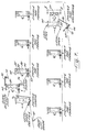
- Figure 1 is a schematic view of the apparatus broadly designated at 20 .
- the apparatus 20 comprises means schematically designated as the bag making station 21 for preparing a bag from plastic film material and for enclosing a foamable composition in the plastic bag.
- bag is used in a broad sense, to designate a sealed container made from flexible sheet material, and could include structures that are also referred to as “envelopes", “pouches”, or other related terms, without departing from the scope of the claims.
- the term “bag” is nevertheless accurate and convenient and will be used throughout this specification.
- the bag making station 21 can comprise any of several devices that form bags while concurrently filling them with a foamable composition.
- Several such devices have been set forth in the background portion of the specification Exemplary devices are also available from the proprietor of this invention, Sealed Air Corporation of Saddle Brook, New Jersey under the trademarks INSTAPACKERTM, VERSAPACKERTM, and SPEEDYPACKERTM, among others. The operation and structure of these devices has been well described in the aforementioned patents and will not be repeated herein except where otherwise necessary to illustrate particular aspects of the present invention.
- the invention further comprises means illustrated in the preferred embodiment as the turntable 22 (driven by an appropriate means and typically by an electric motor) for concurrently aligning one of the molds 23, 25, 27, 29, 31, 33, 35, and 37 with a plastic bag and the bag preparing means 21 .
- the mold designated 23 is illustrated as aligned with the bag making station ("bag preparing means") 21 .
- Figure 1 also illustrates a pad unloading station 24 . It will be understood that the pad unloading station 24 is a position rather than a physical element, and in Figure 1 the mold designated 37 is illustrated at the pad unloading station 24 .
- Figure 1 also illustrates the vacuum source 26 which forms a portion of the means for concurrently aligning a mold with the plastic bag and the bag preparing means. The vacuum source also forms the means for placing the bag containing the foamable composition into the aligned mold as the foamable composition begins to form foam.
- the illustrated embodiment includes a single vacuum source 26 which, as will be described further herein, applies the vacuum only to the mold 23 at the bag making station 21 .
- the invention is not limited to a central vacuum source, but that individual vacuum sources could be associated with each of the molds as well.
- the vacuum source can be entirely conventional motor and fan arrangement, and will not be discussed in detail herein.
- Figure 4 illustrates a number of features of the invention including the means shown as the door 30 for maintaining a bag in the mold 23 until the foamable composition has substantially finished forming foam in a shape conforming to the mold.
- FIG. 4 also illustrates that the bag making station broadly designated at 21 is of the type that prepares the plastic bag from two separate sheets of plastic film material and seals two longitudinal edges and two transverse edges to form the bag.
- the bag making station broadly designated at 21 is of the type that prepares the plastic bag from two separate sheets of plastic film material and seals two longitudinal edges and two transverse edges to form the bag.
- the plastic bag can be prepared from a center-folded sheet of plastic film material by sealing one longitudinal edge and two transverse edges to form the bag (with the center fold forming the fourth edge), or by preparing the bag from a tube of plastic film material and thereafter sealing two transverse edges to form the bag.
- Figure 4 shows that the apparatus 21 comprises means shown as the heat seal strip 32 for separating a plastic bag 34 from the plastic film material 36 after the foamable composition has been placed therein.
- the heat seal strip 32 both heat seals the trailing edge of the bag 34 being made and at the same time severs the bag 34 from the remaining plastic film material 36 in a manner clearly described in U.S. Patent No. 5,376,219, which also describes how the longitudinal side seals are formed.
- Figure 4 also illustrates that the turntable broadly designated at 22 and its top surface portion 41 form a portion of the aligning means that align the bag 34 with the mold 23 before the bag is separated from the plastic film material.
- Figures 2, 3, and 11 also illustrate the turret 38 that supports the top surface 41 .
- Figures 3 and 11 further illustrate that the top surface 41 rides the turret 38 on a plurality (typically four or six) of wheels 39 . In the illustrated embodiment, the wheels 39 are fixed to the turret 38 .
- the means for placing the bag containing the foamable composition into the mold comprises means for applying a vacuum through the mold and to a bag to help position a bag into a mold as the foamable composition begins to form foam.
- the mold designated at 23 in Figures 1 and 4 comprises an assembly of several parts that accomplish the intended purpose.
- the mold assembly 23 includes a rectangular mold support 42 which is generally made of metal and is fixed to the top surface 41 of the turntable 22 .
- the mold support 42 holds the mold insert 43 which is typically formed of wood. Wood is of generally light weight, inexpensive, and easy to work into the required shapes. It will, of course, be understood that a number of other materials are similarly suitable for the mold support 42 and insert 43 .
- the mold insert 43 carries a plurality of holes 44 that permit a vacuum to be respectively applied therethrough.
- the holes are generally small compared to the size of the mold, and thus do not distort the overall shape of the cushion made by the mold, but the applied vacuum pulls the plastic film material into the mold and against the mold walls to help provide good mold definition as well as help hold the bag 34 in alignment with the mold 23 during the desired portion of the operating cycle.
- Figure 2 shows that the vacuum source 26 which is generally positioned under the top surface 41 of the turntable 22 , pulls suction on the mold 23 at the bag making station 21 , and on its exhaust side, pushes air towards the mold 37 at pad unloading station 24 .
- the plurality of holes 44 in the mold insert 43 permit blowing air to be applied through the mold 23 to provide the mold with means for releasing a finished cushion in addition to providing access for the vacuum.
- Figures 2 and 10 also illustrate that in preferred embodiments the apparatus 20 comprises a plurality of molds and the turntable 22 sequentially presents the molds to and aligns the molds with, the bag making station 21 so that the molds sequentially receive plastic bags containing the foamable composition.
- Figure 2 also illustrates that the apparatus 20 further comprises means, illustrated as the infrared detector 45 , for measuring the temperature of the mold insert 44 just prior to placing a bag therein.
- the invention further comprises means for adjusting the amount of foamable composition placed in a bag based upon the measured temperature.
- the volume occupied by a gas is directly proportional to its temperature. Because the foam is formed by the combination of a polymer and a generating gas, the temperature of the foam, or of its surrounding, will have a directly proportional affect on the volume of gas, and thus the volume of foam, formed from any particular amount of precursor compositions. Stated more directly, when the mold (or the ambient temperature) is warmer, the foam tends to expand to a greater degree than when the mold is cooler. Thus, the apparatus 20 adjusts the amount of foamable composition whenever the temperature of the mold changes. Typically, the molds tend to get warmer during operation.
- adjusting the foamable composition based on mold temperature serves several advantageous purposes: it helps produce cushions with a consistent size; it prevents expanding foam from rupturing the bag; it compensates for the extra gas that seems to be generated in a hot mold; and it avoids wasting excess foamable composition, thus providing an economic advantage.
- the characteristics of polyurethane foam are such that the temperature-based differences in the amounts of foam used to make a given sized cushion do not affect its cushioning properties to any noticeable extent.
- the control device that uses the measured temperature to adjust the amount of foam being injected into a bag is of the type generally referred to as a feedback circuit, many examples of which are well known in the art, and an appropriate one can be selected without undue experimentation.
- the preferred embodiments use a personal computer in conjunction with the various feedback controls to carry out this adjustment.
- Such controls and their operation are well known in the art and an exemplary discussion is set forth in Dorf, The Electrical Engineering Handbook, Chapter 93, pages 2099-2153, "Control Systems” (1993) by CRC Press, Inc.
- Figure 2 also illustrates that the apparatus 20 further comprises means shown as the ultrasonic detector 46 for preventing a second bag for being placed in a mold that already carries a bag or finished cushion.
- the detector 46 is most conveniently placed adjacent to the infrared detector 45 . If the ultrasonic detector 46 senses the presence of a finished cushion 47 in the mold insert 43 in the mold 37 at the pad unloading station 24 , the detector 46 signals the bag making station 21 to refrain from making and placing a bag in mold 37 until the finished cushion 47 has been removed.
- Figures 2 and 3 illustrate some additional features of the invention.
- the vacuum source 26 applies the vacuum (or the blowing air) through the respective hoses 50 .
- the hoses 50 are fixed in position to the top surface 41 of the turntable 22 and a vacuum is applied when the hose 50 of the mold ( 23 in the illustrations) to which it is connected reaches the bag making station 21 . In that position, the hose aligns with the fixed pipe 51 of the vacuum source 26 to pull the vacuum on the mold 23 and more particularly through the mold insert 43 and against the bag 34 being positioned therein ( Figure 3).
- the top surface 41 of the turntable 22 has a respective opening therethrough corresponding to each vacuum hose 50 to complete the air flow path between the mold and the vacuum source.
- the apparatus includes not only the molds 43 , but respective doors 30 which, when closed, limit the expansion of the foamable precursors in the bag 34 to the shape defined by the mold insert 43 and the closed door 30 .
- the doors 30 provide the means for maintaining the bag 34 in the mold insert 43 .
- the door 30 opens to receive a bag 34 , closes to maintain the bag 34 in the mold insert 43 , and reopens to permit the bag 34 to be removed from the mold insert 43 .
- the door 30 opens and closes in conjunction with the movement of the turntable 22 and its top surface 41 on the turret 38 .
- the turntable 22 provides the means for opening the door 30 to permit the bag to be positioned in the mold insert 43 , means for closing the door 30 to maintain a bag 34 in the mold 43 while the foamable composition forms foam into a molded bag, and provides the means for reopening the door 30 to remove a molded foam cushion 47 from the mold insert 43 after the foamable composition has substantially finished forming foam.
- FIGS 4 through 13 illustrate the movement of the door 30 in some detail.
- the door 30 opens as the mold 23 reaches the pad unloading station.
- the door remains open as the mold rotates underneath the bag making device 21 .
- the door 20 is closed and remains closed as the mold 23 progresses from position to position along the circumferential path of the turntable.
- the door 30 opens to permit the finished cushion inside to be removed.
- the door 30 is opened and closed by being raised and lowered. It will be understood, however, that the manner in which the doors 30 are mechanically or otherwise opened and closed does not represent a limitation of the invention or of the scope of the claims.
- the door mechanism includes the side arms 55 which are pivotally connected to the doors 30 on each side.
- the door side arms 55 are also connected to a respective pair of gas springs 56 and a rear crossbar 57 .
- the door 30 is held in place by a pivoting top clamp 60 .
- the top clamp 60 and the rear crossbar 57 are connected by a pair of vertically oriented coil springs 61 .
- the springs 61 urge the top clamp 60 to pivot downwardly in the rear and upwardly in the front to unlatch the door 30 .
- the top clamp 60 includes the seat portions 62 that engage the pins 63 which also serve as the pivot attachments of the side arms 55 to the door 30 .
- the door assembly also includes a pivoting bracket 64 at its lowest portions.
- Figure 5 illustrates that the pivoting bracket 64 attaches to a door lift arm 65 with a rolling collar 66 .
- the door lift arm 65 is also pivotally attached to the bottom of the turntable surface 41 by a pivot bracket 67 .
- Figure 6 illustrates another portion of the door latching mechanism.
- This includes the bottom latch 70 which pivots and is biased by a spring 71 against its connection with the pin 72 to the rear locking bar 73 .
- the rear locking bar 73 pivots upon the rear crossbar 57 .
- the locking bar 73 engages the locking elbow 74 on the upper portions of the molded support 42 .
- the locking bar 73 keeps the top clamp 60 pivoted against the door 30 to help keep it closed.
- the rear locking bar 73 is pivoted in a clockwise direction, it releases the top clamp 60 .
- the springs 61 urge the top clamp 60 to pivot rearwardly, thus unclamping the door 30 .
- the rear locking bar 73 pivots clockwise when the bottom latch 70 pivots counterclockwise, through the action of the pivots and the pin 72 .
- Figure 6 illustrates the rear of the mold support with the vacuum hose 50 removed, and thus shows the hose opening 68 in the rear wall of the mold support 42 .
- Figure 7 illustrates the sequential operation of the door. Beginning at the upper left, Figure 7 illustrates a door lift guide 75 which is also illustrated in Figures 9 through 13. As perhaps best illustrated in Figures 9 and 11, the door lift guide 75 is a metal bar or rod that defines a curved path around the turret 38 that begins at a low portion and rises until it is just underneath the turntable surface 41 . From that position, the door lift guide 75 continues in a generally horizontal circular path around the turret 38 of the turntable 22 . Figure 10 also illustrates the relationship among the doors 30 , the door lift arms 65 , and the door lift guide 75 .
- FIG. 7 The sequence illustrated in Figure 7 begins with the door opened following removal of a cushion from the mold.
- a first air cylinder 76 (typically positioned on an arm extending from the turret 38 and underneath the top surface 41 ) pushes the door 30 from the bottom to latch it, while a second air cylinder 77 (typically positioned on an arm adjacent the bag-making means) urges a pivoting locking bar 80 to close the pivoting top clamp 60 and hold the door 30 in place.
- a first air cylinder 76 typically positioned on an arm extending from the turret 38 and underneath the top surface 41
- a second air cylinder 77 (typically positioned on an arm adjacent the bag-making means) urges a pivoting locking bar 80 to close the pivoting top clamp 60 and hold the door 30 in place.
- the mold continues around the turntable thus providing a period of time (one or two minutes is generally sufficient) during which the foamable composition forms foam in a shape limited (and thus defined) by the shape of the mold and the door.
- Figure 7 labels these steps as stations 2-7.
- the bottom latch 70 strikes a stub 81 ( Figures 10 and 12) which, combined with the rotation of the turntable, pivots the bottom latch 70 opposite the direction of rotation, causing the latch 70 to in turn pivot the rear locking bar 73 from the locked to its unlocked position as illustrated in Figure 6.
- Figures 12 and 13 complement one another in illustrating the progression of the door from a fully locked position (Figure 13A), to the position at which the bottom latch 70 hits the stub 81 ( Figure 13B), to the drop of the door lift arm 65 against the cam 82 ( Figures 13C and 13D), until the door reaches its lowest point ( Figure 13E), at which point the door lift guide 75 begins to raise the door to the pad loading position ( Figures 13F, 13G and 13H).
- Figure 13 also illustrates that the lower position of the door is additionally limited by a pair of brackets 83 on the side of the mold support 42 , and that are also illustrated in Figure 4.
- the invention comprises a method of automatically molding defined three-dimensional foam cushions.
- the method comprises preparing a plastic bag from a stock supply of plastic film material.
- the illustrated embodiment forms the bag from two separate sheets of plastic film material by sealing two longitudinal edges and two transverse edges, but the method can also comprise preparing the bag from a center folded sheet of plastic film material and sealing one longitudinal edge and two transverse edges to form the bag. Additionally, the method could also comprise preparing the bag from a tube of plastic film material and sealing the tube with two transverse seals to form the bag.
- FIG. 4 illustrates that (as described in the background) the foamable composition (such as a polyurethane) is typically formed from two components labelled A and B fed by respective hoses 85 and 86 to an injection nozzle 87 from which it is dispensed into the bag 34 being formed.
- the foamable composition such as a polyurethane
- the method next comprises aligning the prepared bag with the three-dimensional mold prior to separating the bag from the stock supply of plastic 36 . It will be understood that this aligning step is one of the features of the invention that distinguishes it from manual, because without it, the necessary replacement step is to place the bag manually in the mold, which is otherwise conventional.
- the aligned bag is then separated from the stock supply of plastic film material and delivered to the three-dimensional mold in which it is maintained until the foamable composition has substantially finished forming foam.
- the step of aligning the bag with the mold typically comprises moving a mold to a position underneath the bag making means, and the step of delivering the bag to the mold comprises applying a vacuum to the mold and dropping the bag into the mold while the vacuum is being applied.
- the method can further comprise the step of releasing the bag from the mold after the foamable composition has formed a foam cushion with the shape of the mold, and in the preferred embodiment, the step of releasing the bag comprises blowing air into the mold to help eject the finished foam cushion therefrom.
- the step of separating the aligned bag from the stock supply of film material generally comprises heat sealing and severing the bag.
Landscapes
- Moulds For Moulding Plastics Or The Like (AREA)
- Manufacture Of Porous Articles, And Recovery And Treatment Of Waste Products (AREA)
- Casting Or Compression Moulding Of Plastics Or The Like (AREA)
- Mattresses And Other Support Structures For Chairs And Beds (AREA)
- Making Paper Articles (AREA)
- Molding Of Porous Articles (AREA)
Abstract
Description
Claims (29)
- An apparatus (20) for automatically molding a defined three-dimensional foam cushion, characterised by:bag preparing means (21) for preparing a bag (34) from solidified plastic film material (36) and for enclosing a foamable composition in the plastic bag, the bag preparing means including means for automatically withdrawing the solidified plastic film material from a stock supply, and means for automatically sealing plastic film portions together at selected locations to form the plastic bag;aligning means for automatically moving a mold (23) into alignment with the plastic bag and the bag preparing means concurrently with the preparation of the bag by the bag preparing means;bag placing means for automatically placing the bag containing the foamable composition into the aligned mold as the foamable composition begins to form foam; andmeans for maintaining the bag in the mold until the foamable composition has substantially finished forming foam in shape conforming to the mold.
- The apparatus according to claim 1, characterised in that the bag preparing means (21) comprises means for separating the plastic bag (34) from the plastic film material after the foamable composition has been placed therein; and the aligning means comprises means for aligning the bag with the mold (23) before the bag is separated from the plastic film material.
- The apparatus according to claim 1 or 2, characterised in that the aligning means (22) comprises a turntable (22) for carrying the mold (23) and for positioning the mold under the bag preparing means (21).
- The apparatus according to any preceding claim, characterised in that the bag placing means comprises vacuum applying means (26, 50, 51) for applying a vacuum through the mold (23) and to the bag (34) to help position the bag in the mold as the foamable composition begins to form foam.
- The apparatus according to any preceding claim, characterised by cushion releasing means (26, 50, 52) for releasing a finished cushion (47) from the mold (23).
- The apparatus according to claim 4 or 5, characterised in that the vacuum applying means (26, 50, 51) and/or the cushion releasing means (26, 50, 52) includes a plurality of holes (44) in the mold (23) that permit a vacuum or blowing air to be respectively applied therethrough.
- The apparatus according to any preceding claim, characterised by a plurality of molds (23) and in that the aligning means comprises means for sequentially presenting and aligning the molds with the bag preparing means so that the molds sequentially receive plastic bags (34) containing the foamable composition.
- The apparatus according to any preceding claim, characterised in that said means for enclosing a foamable composition in the bag (34) comprises means (87) for injecting foamable composition between two plastic sheets while said bag preparing means (21) makes a bag.
- The apparatus according to any preceding claim, characterised in that the means for maintaining the bag in the mold (23) comprises a door (30) that opens to receive the bag (34), closes to maintain the bag in the mold, and reopens to permit the bag to be removed from the mold.
- An apparatus (20) for automatically molding defined three-dimensional foam cushions, characterised by:bag preparing means (21) for preparing a plastic bag (34) filled with a foamable composition from a stock supply of solidified plastic film material (36) and foam precursors (85, 86), the bag preparing means including means for automatically withdrawing the solidified plastic film material from the stock supply, and means for automatically sealing plastic film portions together at selected locations to form the plastic bag;a rotating turntable (22) that carries a plurality of molds (23) for sequentially aligning each of the molds with the bag-preparing means; andbag releasing means for releasing a bag from the bag preparing means and delivering a bag to a mold after the turntable has sequentially aligned a mold with the bag preparing means.
- The apparatus according to claim 10, characterised in that the bag preparing means (21) comprises bag separating means for separating the plastic bag (34) from the stock supply of plastic film material (36) after the foamable composition has been placed therein; and the turntable (22) aligns the bag with a mold (23) before the bag is separated from the plastic film material.
- The apparatus according to claim 11 characterised in that the bag separating means comprises means (32) for heat sealing and severing a bag (34) from the remaining plastic film material (36).
- The apparatus according to claim 10, 11 or 12, characterised in that each mold (23) includes a plurality of small holes (44); and the turntable (22) includes vacuum applying means (26, 50, 51) for applying a vacuum through the holes in the mold and to a bag (34) to help position the bag in the mold as the foamable composition begins to form foam.
- The apparatus according to claim 13, characterised in that the turntable (22) comprises means (26,50,52) for blowing release air through the holes.
- The apparatus according to any one of claims 10 to 14, characterised in that the molds (23) include doors (30) and the turntable (22) includes means for opening each door to permit a bag (34) to be positioned in the mold, means for closing the door to maintain a bag in the mold while the foamable composition forms foam into a molded bag, and means for reopening the door to remove a molded foam cushion (47) from the mold after the foamable composition has substantially finished forming foam.
- The apparatus according to any one of claims 10 to 15, characterised in that the bag preparing means (21) further includes filling means (87) for injecting foamable composition between two plastic sheets while the bag preparing means makes the plastic bag (34).
- The apparatus according to any preceding claim, characterised by measuring means (45) for measuring the temperature of the or each mold (23) just prior to placing the plastic bag (34) therein.
- The apparatus according to claim 17, characterised by adjusting means for adjusting the amount of foamable composition placed in the plastic bag based upon the measured temperature.
- The apparatus according to any preceding claim, characterised by preventing means (46) for preventing a second bag from being placed in the or each mold (23) when it already carries a bag (34) or finished cushion (47).
- The apparatus according to claim 19, characterised in that the preventing means comprises determining means for determining whether the mold (23) carries a bag (34) or cushion (47).
- A method of automatically molding a defined three-dimensional foam cushion, comprising the steps of:preparing a plastic bag (34) from a stock supply of plastic film material (36);placing and sealing a foamable composition in the prepared plastic bag;aligning the prepared bag with a three-dimensional mold (23) prior to separating the bag from the stock supply;separating the aligned bag from the stock supply of plastic film material;delivering the bag and enclosed foamable composition to a three-dimensional mold; andmaintaining the bag in the mold until the foamable composition has substantially finished forming foam.
- The method according to claim 21, wherein the step of preparing the plastic bag (34) comprises preparing the bag from two separate sheets of plastic film material and sealing two longitudinal edges and two transverse edges to form the bag.
- The method according to claim 21, wherein the step of preparing the plastic bag (34) comprises preparing the bag from a center-folded sheet of plastic film material and sealing one longitudinal edge and two transverse edges to form the bag.
- The method according to claim 21, wherein the step of preparing the plastic bag comprises preparing the bag from a tube of plastic film material and sealing the tube with two transverse seals to form the bag.
- The method according to any one of claims 21 to 24, wherein the step of aligning the bag (34) with the mold (23) comprises moving a mold to a position underneath the bag preparing station.
- The method according to any one of claims 21 to 25, wherein the step of delivering the bag (34) to the mold (23) comprises applying a vacuum to the mold and delivering the bag into the mold while the vacuum is being applied.
- The method according to any one of claims 21 to 26, comprising the step of releasing the bag (34) from the mold (23) after the foamable composition has formed a foam cushion (47) with the shape of the mold.
- The method according to claim 27, wherein the step of releasing the bag (34) comprises blowing air into the mold (23) to help eject the finished foam cushion (47) therefrom.
- The method according to any one of claims 21 to 28, wherein the step of separating the aligned bag (34) from the stock supply of film material (36) comprises heat sealing and severing the bag.
Applications Claiming Priority (3)
| Application Number | Priority Date | Filing Date | Title |
|---|---|---|---|
| US08/743,401 US5776510A (en) | 1996-11-01 | 1996-11-01 | On-demand production of foam cushions with defined three-dimensional geometry |
| US743401 | 1996-11-01 | ||
| PCT/US1997/021121 WO1998019844A1 (en) | 1996-11-01 | 1997-10-31 | On-demand production of foam cushions with defined three-dimensional geometry |
Publications (2)
| Publication Number | Publication Date |
|---|---|
| EP0935521A1 EP0935521A1 (en) | 1999-08-18 |
| EP0935521B1 true EP0935521B1 (en) | 2000-12-20 |
Family
ID=24988644
Family Applications (1)
| Application Number | Title | Priority Date | Filing Date |
|---|---|---|---|
| EP97948376A Expired - Lifetime EP0935521B1 (en) | 1996-11-01 | 1997-10-31 | On-demand production of foam cushions with defined three-dimensional geometry |
Country Status (12)
| Country | Link |
|---|---|
| US (1) | US5776510A (en) |
| EP (1) | EP0935521B1 (en) |
| JP (1) | JP2001503345A (en) |
| AT (1) | ATE198176T1 (en) |
| AU (1) | AU718642B2 (en) |
| BR (1) | BR9712853A (en) |
| CA (1) | CA2269625C (en) |
| DE (1) | DE69703747T2 (en) |
| DK (1) | DK0935521T3 (en) |
| ES (1) | ES2153691T3 (en) |
| TW (1) | TW379186B (en) |
| WO (1) | WO1998019844A1 (en) |
Cited By (4)
| Publication number | Priority date | Publication date | Assignee | Title |
|---|---|---|---|---|
| US6789376B1 (en) | 1999-09-22 | 2004-09-14 | Pactiv Corporation | Method and machine for the manufacture of air pillows |
| US6932134B2 (en) | 2003-02-07 | 2005-08-23 | Pactiv Corporation | Devices and methods for manufacturing packaging materials |
| US8627637B2 (en) | 1999-09-22 | 2014-01-14 | Pregis Innovative Packaging, Inc. | Method and machine for the manufacture of air pillows |
| US8906478B2 (en) | 2005-05-06 | 2014-12-09 | Pregis Innovative Packaging, Inc. | Films for inflatable cushions |
Families Citing this family (28)
| Publication number | Priority date | Publication date | Assignee | Title |
|---|---|---|---|---|
| US6178725B1 (en) | 1998-05-12 | 2001-01-30 | Carpenter Company | Apparatus and method for producing bags and foam-in-bag cushions |
| US6691490B1 (en) * | 1998-06-30 | 2004-02-17 | Kabushiki Kaisha Yuyama Seisakusho | Injection drug packaging device |
| US6289649B1 (en) * | 1998-10-16 | 2001-09-18 | Sealed Air Corporation(Us) | Foam diverter assembly for use in producing foam cushions |
| NO309638B1 (en) * | 1999-06-02 | 2001-03-05 | Spilka Ind As | Method and apparatus for making composite product |
| US6386850B1 (en) * | 2000-03-21 | 2002-05-14 | Sealed Air Corporation (Us) | Machine for forming molded foam cushions |
| US6283174B1 (en) | 2000-07-27 | 2001-09-04 | Sealed Air Corporation | Cleaning mechanism for fluid dispenser |
| US6996956B2 (en) * | 2001-01-12 | 2006-02-14 | Sealed Air Corporation (Us) | Fluid dispenser having improved cleaning solvent delivery system |
| US6675557B2 (en) | 2001-01-12 | 2004-01-13 | Sealed Air Corporation (Us) | Apparatus for dispensing fluid into pre-formed, flexible containers and enclosing the fluid within the containers |
| US6550229B2 (en) | 2001-01-12 | 2003-04-22 | Sealed Air Corporation (Us) | Device for sealing two plies of film together, particularly for enclosing a foamable composition in a flexible container |
| US6929193B2 (en) | 2002-03-13 | 2005-08-16 | Sealed Air Corporation | Tip for a foam-in-place dispenser |
| US6923932B2 (en) * | 2002-12-12 | 2005-08-02 | Intertec Systems, Llc | Composite structure tightly radiused molding method |
| US6811059B2 (en) * | 2003-02-24 | 2004-11-02 | Sealed Air Corporation (Us) | Self-cleaning fluid dispenser |
| US7386969B2 (en) * | 2003-05-09 | 2008-06-17 | Intellipack | Exterior configuration of a foam-in-bag dispenser assembly |
| ITBO20040513A1 (en) * | 2004-08-06 | 2004-11-06 | Elopak Systems | HEAT-SEALING STATION FOR THE CREATION OF THERMOFORMABLE AND THERMAL WELDABLE CONTAINERS |
| EP1658948A3 (en) * | 2004-11-22 | 2007-12-26 | N.V. Soudan Patrimonium And Consulting | A device for manufacturing foam cushions |
| ITBO20050302A1 (en) * | 2005-05-02 | 2006-11-03 | Elopak Systems | EQUIPMENT AND METHOD FOR THE CONSTRUCTION OF THERMOFORMED AND THERMAL WELDED CONTAINERS |
| US20070068353A1 (en) * | 2005-09-26 | 2007-03-29 | Sealed Air Corporation | Machine for severing a web |
| US7984893B2 (en) * | 2006-02-13 | 2011-07-26 | Rco Engineering | Reusable support for a contoured surface of a part allowing machining of an opposite side of the part |
| US7641459B2 (en) * | 2006-05-01 | 2010-01-05 | Sealed Air Corporation (Us) | Foam cushion molding system and method |
| US20080000204A1 (en) * | 2006-06-28 | 2008-01-03 | S.C. Johnson Home Storage, Inc. | Vacuum sealer apparatus and a film cartridge for a vacuum sealer and a means of operating the vacuum sealer and the film cartridge |
| US7553437B2 (en) * | 2007-05-10 | 2009-06-30 | Sealed Air Corporation (Us) | Method and mold assembly for making a molded foam article |
| US8511047B2 (en) * | 2007-08-07 | 2013-08-20 | Sealed Air Corporation (Us) | Device for mixing and dispensing fluids |
| US20090108491A1 (en) * | 2007-10-25 | 2009-04-30 | Sealed Air Corporation (Us) | Mold, mold image and method for making a molded article |
| US20110037205A1 (en) * | 2009-08-17 | 2011-02-17 | Russo Peter A | Foam costumes |
| US9623622B2 (en) | 2010-02-24 | 2017-04-18 | Michael Baines | Packaging materials and methods |
| US9033694B2 (en) | 2012-02-16 | 2015-05-19 | Sealed Air Corporation (Us) | Molding apparatus and method |
| US9028238B2 (en) | 2012-02-16 | 2015-05-12 | Sealed Air Corporation (Us) | Molding apparatus and method |
| CN115520420B (en) * | 2022-10-17 | 2024-04-23 | 兰州理工大学 | A kind of anti-corrosion sealed packaging equipment for fruits and vegetables |
Family Cites Families (31)
| Publication number | Priority date | Publication date | Assignee | Title |
|---|---|---|---|---|
| GB989950A (en) * | 1961-06-13 | 1965-04-22 | Griswold Corp 1961 Ltd | Method and apparatus for forming, filling and sealing bags, particularly for potato chips |
| US3268636A (en) * | 1963-07-01 | 1966-08-23 | Union Carbide Corp | Method and apparatus for injection molding foamed plastic articles |
| US3330407A (en) * | 1964-08-14 | 1967-07-11 | Corning Glass Works | Universal tv bulb packaging insert |
| US3566449A (en) * | 1968-11-27 | 1971-03-02 | Phillips Petroleum Co | Apparatus for molding plastic foam |
| US4053549A (en) * | 1975-01-06 | 1977-10-11 | Mobil Oil Corporation | Method of embossing foam polystyrene to prevent warping upon removal from mold |
| FR2428519A1 (en) * | 1978-06-13 | 1980-01-11 | Ameublement Ind Et Tech | PLUG FOR CAST HOLE OF EXPANDED MATERIAL IN A MOLD |
| US4208368A (en) * | 1978-07-18 | 1980-06-17 | Gebruder Buhler Ag | Method and apparatus for injection molding foamed plastic articles using a pre-pressurized mold having fixed core members with controlled venting |
| US4240557A (en) * | 1978-12-28 | 1980-12-23 | The Mead Corporation | Polystyrene foam structure |
| DE3120519A1 (en) * | 1981-05-22 | 1982-12-09 | Metzeler Schaum Gmbh, 8940 Memmingen | MOLDING FOAM SYSTEM |
| EP0080171B1 (en) * | 1981-11-20 | 1988-06-08 | Hitachi, Ltd. | Heat-insulating moulding and process for preparing the same |
| US4479914A (en) * | 1982-11-01 | 1984-10-30 | Cashiers Plastics | Process and mold for molding foamed plastic articles |
| DE3246368A1 (en) * | 1982-12-15 | 1984-06-20 | Dynamit Nobel Ag, 5210 Troisdorf | METHOD FOR EMBELLISHING SOFT-ELASTIC FOAM LINES |
| US5098621A (en) * | 1985-01-07 | 1992-03-24 | Twin Rivers Engineering | Method of forming a foam substrate and micropackaged active ingredient particle composite |
| US4674268A (en) * | 1985-09-26 | 1987-06-23 | Sealed Air Corporation | Apparatus and method for forming foam cushions for packaging purposes |
| AT383543B (en) * | 1985-12-16 | 1987-07-10 | Rakoczy Jozef | METHOD FOR PRODUCING RELIEF IMAGES |
| FR2598967B1 (en) * | 1986-05-23 | 1988-11-25 | Roth Sa Freres | PROCESS FOR MANUFACTURING POLYURETHANE FOAM MOLDED MATTRESSES COMPRISING SEVERAL DIFFERENT FLEXIBLE AREAS AND MATTRESSES THUS PRODUCED |
| DE3708006A1 (en) * | 1987-03-12 | 1988-09-22 | Kautex Maschinenbau Gmbh | METHOD FOR PRODUCING HOLLOW BODIES FROM THERMOPLASTIC PLASTIC WITH A MULTILAYERED WALL |
| US4801260A (en) * | 1987-03-23 | 1989-01-31 | Graham Engineering Corp. | Rotary blow molding machine |
| US4783292A (en) * | 1987-06-15 | 1988-11-08 | Rogers Roy K | Method of injection molding a foamed plastic article using a relatively light gas as a blowing agent |
| US5401456A (en) * | 1987-10-07 | 1995-03-28 | Formex Manufacturing, Inc. | Method of forming a plastic unit having an outer plastic shell encapsulating a foam core |
| US4938007A (en) * | 1987-11-16 | 1990-07-03 | Sealed Air Corporation | Apparatus and method for forming foam cushions for packaging purposes |
| DE3813587A1 (en) * | 1988-04-22 | 1989-11-02 | Bayer Ag | METHOD FOR PRODUCING FOAM PADS |
| GB2219237A (en) * | 1988-06-01 | 1989-12-06 | John Hine Limited | Shaped packaging |
| US4999975A (en) * | 1989-04-28 | 1991-03-19 | Insta-Foam Products, Inc. | Apparatus and methods for dispensing foamable products |
| US5027583A (en) * | 1989-07-11 | 1991-07-02 | Sealed Air Corporation | Method of forming foam cushions for packaging purposes |
| US5376219A (en) * | 1991-09-26 | 1994-12-27 | Sealed Air Corporation | High speed apparatus for forming foam cushions for packaging purposes |
| IT1252680B (en) * | 1991-11-13 | 1995-06-23 | Sviluppo Settori Impiego Srl | PROCEDURE FOR THE PRODUCTION OF POLYMERIC MATERIAL BODIES INCLUDING A CORE OF EXPANDED MATERIAL ENCLOSED BY AN EXTERNAL SHELL, AND A DEVICE USED IN SUCH PROCEDURE |
| EP0557956B1 (en) * | 1992-02-28 | 1997-08-20 | Sealed Air Corporation | Compact packaging device for forming foam-filled cushions and related method |
| MY116615A (en) * | 1992-07-13 | 2004-03-31 | Aron Kasei Kk | Process for producing expanded plastics with skin and molding apparatus therefor |
| US5335483A (en) * | 1992-09-02 | 1994-08-09 | Sealed Air Corporation | Method and apparatus for producing foam cushions for packaging purposes |
| US5555709A (en) * | 1995-10-10 | 1996-09-17 | Ag-Pak, Inc. | Carousel bagger machine |
-
1996
- 1996-11-01 US US08/743,401 patent/US5776510A/en not_active Expired - Lifetime
-
1997
- 1997-10-30 TW TW086116285A patent/TW379186B/en active
- 1997-10-31 DE DE69703747T patent/DE69703747T2/en not_active Expired - Lifetime
- 1997-10-31 AT AT97948376T patent/ATE198176T1/en not_active IP Right Cessation
- 1997-10-31 ES ES97948376T patent/ES2153691T3/en not_active Expired - Lifetime
- 1997-10-31 AU AU54461/98A patent/AU718642B2/en not_active Ceased
- 1997-10-31 EP EP97948376A patent/EP0935521B1/en not_active Expired - Lifetime
- 1997-10-31 CA CA002269625A patent/CA2269625C/en not_active Expired - Fee Related
- 1997-10-31 JP JP52190798A patent/JP2001503345A/en active Pending
- 1997-10-31 DK DK97948376T patent/DK0935521T3/en active
- 1997-10-31 WO PCT/US1997/021121 patent/WO1998019844A1/en not_active Ceased
- 1997-10-31 BR BR9712853-8A patent/BR9712853A/en active Search and Examination
Cited By (5)
| Publication number | Priority date | Publication date | Assignee | Title |
|---|---|---|---|---|
| US6789376B1 (en) | 1999-09-22 | 2004-09-14 | Pactiv Corporation | Method and machine for the manufacture of air pillows |
| US8627637B2 (en) | 1999-09-22 | 2014-01-14 | Pregis Innovative Packaging, Inc. | Method and machine for the manufacture of air pillows |
| US6932134B2 (en) | 2003-02-07 | 2005-08-23 | Pactiv Corporation | Devices and methods for manufacturing packaging materials |
| US7347911B2 (en) | 2003-02-07 | 2008-03-25 | Pregis Innovative Packaging Inc. | Devices and methods for manufacturing packaging materials |
| US8906478B2 (en) | 2005-05-06 | 2014-12-09 | Pregis Innovative Packaging, Inc. | Films for inflatable cushions |
Also Published As
| Publication number | Publication date |
|---|---|
| ATE198176T1 (en) | 2001-01-15 |
| US5776510A (en) | 1998-07-07 |
| DE69703747T2 (en) | 2004-08-19 |
| TW379186B (en) | 2000-01-11 |
| WO1998019844A1 (en) | 1998-05-14 |
| ES2153691T3 (en) | 2001-03-01 |
| CA2269625A1 (en) | 1998-05-14 |
| CA2269625C (en) | 2002-08-13 |
| AU5446198A (en) | 1998-05-29 |
| DE69703747D1 (en) | 2004-05-06 |
| BR9712853A (en) | 1999-12-07 |
| AU718642B2 (en) | 2000-04-20 |
| DK0935521T3 (en) | 2001-01-15 |
| JP2001503345A (en) | 2001-03-13 |
| EP0935521A1 (en) | 1999-08-18 |
Similar Documents
| Publication | Publication Date | Title |
|---|---|---|
| EP0935521B1 (en) | On-demand production of foam cushions with defined three-dimensional geometry | |
| US6386850B1 (en) | Machine for forming molded foam cushions | |
| CN103402876B (en) | For the vacuum-packed device of particularly food | |
| US10160585B2 (en) | Inflatable structure for packaging and associated apparatus and methods | |
| JP4083237B2 (en) | Pneumatic cushion forming machine | |
| EP0225976B1 (en) | Formation of foam cushions for packaging purposes | |
| CN102648084B (en) | Inflatable mailer and method of making same | |
| EP0930961B1 (en) | Making foam cushioning panels for packaging purposes | |
| JPH08207174A (en) | Method and device for manufacturing packaging container | |
| WO1998019844B1 (en) | On-demand production of foam cushions with defined three-dimensional geometry | |
| KR20050028041A (en) | Packing machine, packing method, and packing system | |
| MX2013014565A (en) | Dispensing and sealing system. | |
| US7553437B2 (en) | Method and mold assembly for making a molded foam article | |
| US20090108491A1 (en) | Mold, mold image and method for making a molded article | |
| US3877197A (en) | Method and apparatus for filling and sealing plastic containers | |
| MXPA99003999A (en) | On-demand production of foam cushions with defined three-dimensional geometry | |
| US5713185A (en) | Wrapping method for producing a package and for wrapping an article | |
| GB2219237A (en) | Shaped packaging | |
| JP2001261014A (en) | Packaging bag cutting method, apparatus thereof, and bagging and packaging apparatus of work | |
| KR20050015944A (en) | A Packing Apparatus for Grains and a Manufacturing Method for Packages | |
| JP2004255723A (en) | Method for recovering surplus raw material particles and foam molding apparatus | |
| PL79949B1 (en) | Plastics containers and method of sealing them[my7300043a] | |
| JPH0656103A (en) | Packaging apparatus | |
| MXPA99007919A (en) | Inflatable cushion forming machine |
Legal Events
| Date | Code | Title | Description |
|---|---|---|---|
| PUAI | Public reference made under article 153(3) epc to a published international application that has entered the european phase |
Free format text: ORIGINAL CODE: 0009012 |
|
| 17P | Request for examination filed |
Effective date: 19990528 |
|
| AK | Designated contracting states |
Kind code of ref document: A1 Designated state(s): AT BE CH DE DK ES FR GB IE IT LI NL SE |
|
| GRAG | Despatch of communication of intention to grant |
Free format text: ORIGINAL CODE: EPIDOS AGRA |
|
| 17Q | First examination report despatched |
Effective date: 20000128 |
|
| GRAG | Despatch of communication of intention to grant |
Free format text: ORIGINAL CODE: EPIDOS AGRA |
|
| GRAG | Despatch of communication of intention to grant |
Free format text: ORIGINAL CODE: EPIDOS AGRA |
|
| GRAH | Despatch of communication of intention to grant a patent |
Free format text: ORIGINAL CODE: EPIDOS IGRA |
|
| GRAH | Despatch of communication of intention to grant a patent |
Free format text: ORIGINAL CODE: EPIDOS IGRA |
|
| GRAA | (expected) grant |
Free format text: ORIGINAL CODE: 0009210 |
|
| AK | Designated contracting states |
Kind code of ref document: B1 Designated state(s): AT BE CH DE DK ES FR GB IE IT LI NL SE |
|
| REF | Corresponds to: |
Ref document number: 198176 Country of ref document: AT Date of ref document: 20010115 Kind code of ref document: T |
|
| REG | Reference to a national code |
Ref country code: CH Ref legal event code: EP |
|
| REG | Reference to a national code |
Ref country code: DK Ref legal event code: T3 |
|
| REG | Reference to a national code |
Ref country code: IE Ref legal event code: FG4D |
|
| ET | Fr: translation filed | ||
| REG | Reference to a national code |
Ref country code: ES Ref legal event code: FG2A Ref document number: 2153691 Country of ref document: ES Kind code of ref document: T3 |
|
| ITF | It: translation for a ep patent filed | ||
| REG | Reference to a national code |
Ref country code: CH Ref legal event code: NV Representative=s name: KIRKER & CIE SA |
|
| PLBE | No opposition filed within time limit |
Free format text: ORIGINAL CODE: 0009261 |
|
| STAA | Information on the status of an ep patent application or granted ep patent |
Free format text: STATUS: NO OPPOSITION FILED WITHIN TIME LIMIT |
|
| 26N | No opposition filed | ||
| REG | Reference to a national code |
Ref country code: GB Ref legal event code: IF02 |
|
| PGFP | Annual fee paid to national office [announced via postgrant information from national office to epo] |
Ref country code: SE Payment date: 20021004 Year of fee payment: 6 |
|
| PGFP | Annual fee paid to national office [announced via postgrant information from national office to epo] |
Ref country code: AT Payment date: 20021011 Year of fee payment: 6 |
|
| PGFP | Annual fee paid to national office [announced via postgrant information from national office to epo] |
Ref country code: DK Payment date: 20021014 Year of fee payment: 6 |
|
| PGFP | Annual fee paid to national office [announced via postgrant information from national office to epo] |
Ref country code: IE Payment date: 20021029 Year of fee payment: 6 |
|
| PGFP | Annual fee paid to national office [announced via postgrant information from national office to epo] |
Ref country code: CH Payment date: 20021101 Year of fee payment: 6 |
|
| PG25 | Lapsed in a contracting state [announced via postgrant information from national office to epo] |
Ref country code: LI Free format text: LAPSE BECAUSE OF NON-PAYMENT OF DUE FEES Effective date: 20031031 Ref country code: IE Free format text: LAPSE BECAUSE OF NON-PAYMENT OF DUE FEES Effective date: 20031031 Ref country code: DK Free format text: LAPSE BECAUSE OF NON-PAYMENT OF DUE FEES Effective date: 20031031 Ref country code: CH Free format text: LAPSE BECAUSE OF NON-PAYMENT OF DUE FEES Effective date: 20031031 Ref country code: AT Free format text: LAPSE BECAUSE OF NON-PAYMENT OF DUE FEES Effective date: 20031031 |
|
| PG25 | Lapsed in a contracting state [announced via postgrant information from national office to epo] |
Ref country code: SE Free format text: LAPSE BECAUSE OF NON-PAYMENT OF DUE FEES Effective date: 20031101 |
|
| REF | Corresponds to: |
Ref document number: 69703747 Country of ref document: DE Date of ref document: 20040506 Kind code of ref document: P |
|
| REG | Reference to a national code |
Ref country code: DK Ref legal event code: EBP |
|
| REG | Reference to a national code |
Ref country code: CH Ref legal event code: PL |
|
| EUG | Se: european patent has lapsed | ||
| REG | Reference to a national code |
Ref country code: IE Ref legal event code: MM4A |
|
| PGFP | Annual fee paid to national office [announced via postgrant information from national office to epo] |
Ref country code: NL Payment date: 20061024 Year of fee payment: 10 |
|
| PGFP | Annual fee paid to national office [announced via postgrant information from national office to epo] |
Ref country code: BE Payment date: 20061124 Year of fee payment: 10 |
|
| BERE | Be: lapsed |
Owner name: *SEALED AIR CORP. Effective date: 20071031 |
|
| NLV4 | Nl: lapsed or anulled due to non-payment of the annual fee |
Effective date: 20080501 |
|
| PG25 | Lapsed in a contracting state [announced via postgrant information from national office to epo] |
Ref country code: BE Free format text: LAPSE BECAUSE OF NON-PAYMENT OF DUE FEES Effective date: 20071031 |
|
| PG25 | Lapsed in a contracting state [announced via postgrant information from national office to epo] |
Ref country code: NL Free format text: LAPSE BECAUSE OF NON-PAYMENT OF DUE FEES Effective date: 20080501 |
|
| PGFP | Annual fee paid to national office [announced via postgrant information from national office to epo] |
Ref country code: FR Payment date: 20131017 Year of fee payment: 17 Ref country code: GB Payment date: 20131028 Year of fee payment: 17 Ref country code: DE Payment date: 20131029 Year of fee payment: 17 |
|
| PGFP | Annual fee paid to national office [announced via postgrant information from national office to epo] |
Ref country code: ES Payment date: 20131028 Year of fee payment: 17 Ref country code: IT Payment date: 20131025 Year of fee payment: 17 |
|
| REG | Reference to a national code |
Ref country code: DE Ref legal event code: R119 Ref document number: 69703747 Country of ref document: DE |
|
| GBPC | Gb: european patent ceased through non-payment of renewal fee |
Effective date: 20141031 |
|
| PG25 | Lapsed in a contracting state [announced via postgrant information from national office to epo] |
Ref country code: DE Free format text: LAPSE BECAUSE OF NON-PAYMENT OF DUE FEES Effective date: 20150501 Ref country code: GB Free format text: LAPSE BECAUSE OF NON-PAYMENT OF DUE FEES Effective date: 20141031 |
|
| REG | Reference to a national code |
Ref country code: FR Ref legal event code: ST Effective date: 20150630 |
|
| PG25 | Lapsed in a contracting state [announced via postgrant information from national office to epo] |
Ref country code: FR Free format text: LAPSE BECAUSE OF NON-PAYMENT OF DUE FEES Effective date: 20141031 Ref country code: IT Free format text: LAPSE BECAUSE OF NON-PAYMENT OF DUE FEES Effective date: 20141031 |
|
| REG | Reference to a national code |
Ref country code: ES Ref legal event code: FD2A Effective date: 20151127 |
|
| PG25 | Lapsed in a contracting state [announced via postgrant information from national office to epo] |
Ref country code: ES Free format text: LAPSE BECAUSE OF NON-PAYMENT OF DUE FEES Effective date: 20141101 |