EP0930130B1 - Clamping device - Google Patents
Clamping device Download PDFInfo
- Publication number
- EP0930130B1 EP0930130B1 EP99100659A EP99100659A EP0930130B1 EP 0930130 B1 EP0930130 B1 EP 0930130B1 EP 99100659 A EP99100659 A EP 99100659A EP 99100659 A EP99100659 A EP 99100659A EP 0930130 B1 EP0930130 B1 EP 0930130B1
- Authority
- EP
- European Patent Office
- Prior art keywords
- actuator
- clamping device
- module
- pressure
- clamping
- Prior art date
- Legal status (The legal status is an assumption and is not a legal conclusion. Google has not performed a legal analysis and makes no representation as to the accuracy of the status listed.)
- Expired - Lifetime
Links
Images



Classifications
-
- B—PERFORMING OPERATIONS; TRANSPORTING
- B25—HAND TOOLS; PORTABLE POWER-DRIVEN TOOLS; MANIPULATORS
- B25B—TOOLS OR BENCH DEVICES NOT OTHERWISE PROVIDED FOR, FOR FASTENING, CONNECTING, DISENGAGING, OR HOLDING
- B25B5/00—Clamps
- B25B5/06—Arrangements for positively actuating jaws
- B25B5/061—Arrangements for positively actuating jaws with fluid drive
-
- B—PERFORMING OPERATIONS; TRANSPORTING
- B25—HAND TOOLS; PORTABLE POWER-DRIVEN TOOLS; MANIPULATORS
- B25B—TOOLS OR BENCH DEVICES NOT OTHERWISE PROVIDED FOR, FOR FASTENING, CONNECTING, DISENGAGING, OR HOLDING
- B25B5/00—Clamps
- B25B5/06—Arrangements for positively actuating jaws
- B25B5/12—Arrangements for positively actuating jaws using toggle links
- B25B5/122—Arrangements for positively actuating jaws using toggle links with fluid drive
-
- B—PERFORMING OPERATIONS; TRANSPORTING
- B25—HAND TOOLS; PORTABLE POWER-DRIVEN TOOLS; MANIPULATORS
- B25B—TOOLS OR BENCH DEVICES NOT OTHERWISE PROVIDED FOR, FOR FASTENING, CONNECTING, DISENGAGING, OR HOLDING
- B25B5/00—Clamps
- B25B5/16—Details, e.g. jaws, jaw attachments
-
- F—MECHANICAL ENGINEERING; LIGHTING; HEATING; WEAPONS; BLASTING
- F15—FLUID-PRESSURE ACTUATORS; HYDRAULICS OR PNEUMATICS IN GENERAL
- F15B—SYSTEMS ACTING BY MEANS OF FLUIDS IN GENERAL; FLUID-PRESSURE ACTUATORS, e.g. SERVOMOTORS; DETAILS OF FLUID-PRESSURE SYSTEMS, NOT OTHERWISE PROVIDED FOR
- F15B15/00—Fluid-actuated devices for displacing a member from one position to another; Gearing associated therewith
- F15B15/20—Other details, e.g. assembly with regulating devices
- F15B15/202—Externally-operated valves mounted in or on the actuator
-
- F—MECHANICAL ENGINEERING; LIGHTING; HEATING; WEAPONS; BLASTING
- F15—FLUID-PRESSURE ACTUATORS; HYDRAULICS OR PNEUMATICS IN GENERAL
- F15B—SYSTEMS ACTING BY MEANS OF FLUIDS IN GENERAL; FLUID-PRESSURE ACTUATORS, e.g. SERVOMOTORS; DETAILS OF FLUID-PRESSURE SYSTEMS, NOT OTHERWISE PROVIDED FOR
- F15B15/00—Fluid-actuated devices for displacing a member from one position to another; Gearing associated therewith
- F15B15/20—Other details, e.g. assembly with regulating devices
- F15B15/28—Means for indicating the position, e.g. end of stroke
- F15B15/2807—Position switches, i.e. means for sensing of discrete positions only, e.g. limit switches
Definitions
- Such a tensioning device is, for example, according to DE-U-87 14 390.9 known.
- This tensioning device consists, as in essentially all other comparable clamping devices also, from a pressure medium operated actuator with a so-called interface for pressure and Electrical connections, the actuator being linear movable actuator and one in the head of the clamping device arranged adjusting mechanism with a swivel mounted tension arm is connected and the actuator a position interrogation device with electrical position interrogation connections assigned.
- the so-called Interface is from the bottom cover of the Actuator or the actuating cylinder formed.
- the electronics module III ' can be found under Elimination of the connection 11 'of the interrogation device 7 can also be designed such that it can be connected directly to the head 4 with an extension 26 (see FIG. 16A).
- the electronics module III ' is also provided with a plug 23 for a so-called BUS connection and can also have an additional plug 24 in order, for example, to be able to connect workpiece sensors which indicate that a workpiece to be clamped is in position in order to be clamped ,
- the connection for the pressure medium supply is not shown on valve module II '.
- the lower end cover 25 of the actuator 1 is of course here, as in the above-described embodiments according to FIGS. 1 to 15, in a more detachable connection with the actual cylinder of the actuator 1, in order to replace it, if necessary, with a damping module in the sense of FIG to be able to.
Landscapes
- Engineering & Computer Science (AREA)
- Mechanical Engineering (AREA)
- Physics & Mathematics (AREA)
- Fluid Mechanics (AREA)
- General Engineering & Computer Science (AREA)
- Jigs For Machine Tools (AREA)
- Clamps And Clips (AREA)
Description
Die Erfindung betrifft eine Spannvorrichtung zum Festspannen
von Werkstücken gemäß den Oberbegriffen der Patentansprüche
1 und 11.The invention relates to a clamping device for clamping
of workpieces according to the preambles of the
Eine derartige Spannvorrichtung ist bspw. nach der DE-U-87 14 390.9 bekannt. Diese Spannvorrichtung besteht, wie im wesentlichen alle anderen vergleichbaren Spannvorrichtungen auch, aus einem druckmittelbetriebenen Stellantrieb mit einer sogenannten Schnittstelle für Druckmittel- und Elektroanschlüsse, wobei der Stellantrieb über ein linear bewegbares Stellglied und über eine im Kopf der Spannvorrichtung angeordnete Stellmechanik mit einem schwenkbar gelagerten Spannarm in Verbindung steht und dem Stellglied eine Positionsabfrageeinrichtung mit elektrischen Positionsabfrageanschlüssen zugeordnet ist. Die sogenannte Schnittstelle wird dabei vom unteren Abschlußdeckel des Stellantriebes bzw. des Betätigungszylinders gebildet.Such a tensioning device is, for example, according to DE-U-87 14 390.9 known. This tensioning device consists, as in essentially all other comparable clamping devices also, from a pressure medium operated actuator with a so-called interface for pressure and Electrical connections, the actuator being linear movable actuator and one in the head of the clamping device arranged adjusting mechanism with a swivel mounted tension arm is connected and the actuator a position interrogation device with electrical position interrogation connections assigned. The so-called Interface is from the bottom cover of the Actuator or the actuating cylinder formed.
Derartige Spannvorrichtungen werden in der Mehrzahl der Fälle nicht allein, sondern gleichzeitig im sogenannten Anlagenverbund mit mehreren anderen gleichartigen oder auch unterschiedlichen Spannvorrichtungen betrieben. Dazu ist es erforderlich, Positionsabfrageeinrichtungen und Stellantriebe aller Spannvorrichtungen mit einer zentralen Steuer- bzw. Regelung einer solchen Anlage zu verbinden. Erschwerend kommt hinzu, daß dabei die Spannvorrichtungen in der Regel unterschiedliche Funktionen zu erfüllen haben und dementsprechend ausgestattet und gesteuert bzw. geregelt sein müssen. Bspw. ist es bei besonders schnell öffnenden Spannvorrichtungen erforderlich, daß im Fuß des Stellantriebes eine sogenannte Endlagendämpfung vorgesehen sein muß. Ferner ist es bei separat, im Gegensatz zu parallel arbeitenden Spannvorrichtungen erforderlich, diese jeweils separat mit der Steuer- bzw. Regelung der Anlage zu verbinden. Es muß folglich je nach Anwendungszweck entschieden werden, welche speziell ausgebildete Spannvorrichtung einzusetzen ist.Such clamping devices are used in the majority of cases not alone, but at the same time in the so-called System group with several other similar or also operated different clamping devices. To it is necessary to use position interrogators and Actuators of all clamping devices with a central one To connect control or regulation of such a system. To make matters worse, the tensioning devices usually have different functions to perform and equipped and controlled accordingly have to be. For example. it is particularly quick opening Clamps required that in the foot of the Actuator provided a so-called end position damping have to be. It is also separate, as opposed to parallel working fixtures required this each separately with the control or regulation of the system connect to. It must therefore be decided depending on the application be what specially trained jig is to be used.
Der Erfindung liegt die Aufgabe zugrunde, eine Spannvorrichtung der eingangs genannten Art dahingehend zu verbessern, daß sie an verschiedenartige Anschluß- und Funktionserfordernisse auf einfache Weise anpaßbar ist, diese also an sich typengleich, aber funktionsangepaßt an unterschiedlichen Funktionsstellen einer ganzen Anlage zum Einsatz kommen kann.The invention has for its object a tensioning device of the type mentioned at the outset to improve that they have different connection and functional requirements is easily customizable, this In other words, of the same type, but adapted to different functions Functional points of an entire system for use can come.
Diese Aufgabe ist mit einer Spannvorrichtung der eingangs
genannten Art nach der Erfindung durch die im Kennzeichen
des Patentanspruches 1 angeführten Merkmale gelöst.
Da die Anordnung der einzelnen Module, und zwar einzeln
oder in Kombination am unteren Ende des Stellantriebes
nicht zwingend ist, kann die Modulanordnung auch parallel
neben dem Stellantrieb vorgesehen werden, was im zweiten
unabhängigen Patentanspruch Anspruch 11, erfaßt ist, in dieser Ausbildung
zum gleichen Ergebnis führt und in der Mehrzahl der
Fälle sogar zu bevorzugen ist, da dies in der Regel die
An- bzw. Einbauverhältnisse an einem Anordnungsgestell einer
solchen Anlage eher erfordern.This task is with a jig the beginning
mentioned type according to the invention by the in the mark
of
Diesen beiden Lösungen liegt der Gedanke zugrunde, an einer Spannvorrichtung deren Schnittstelle derart auszubilden, daß an dieser verschiedenartige, zur eigentlichen Schnittstelle passende Anschlußmodule, und zwar auch untereinander passend, zugeordnet werden können, um den unterschiedlichen Anschluß- und Funktionserfordernissen der jeweiligen Spannvorrichtung gerecht zu werden. Letztlich bedeutet dies, daß die bislang üblichen, zentralen Steuerungen mit ihren aufwendigen Leitungsführungen zu den einzelnen Spannvorrichtungen aufgelöst und die für die Steuerung und Regelung jeder Spannvorrichtung notwendigen Elemente funktionsspezifisch unmittelbar an den ansonsten im wesentlichen gleich ausgebildeten Spannvorrichtungen selbst angeordnet sind.These two solutions are based on the idea of one To design the clamping device, its interface, that on this different, to the actual Interface suitable connection modules, also among themselves suitable, can be assigned to the different Connection and functional requirements of the to meet each clamping device. Ultimately this means that the central controls that have been common until now with their elaborate cable routing to the individual Clamps released and those for control and regulation of each clamping device necessary elements function-specific directly at the otherwise in essentially identical clamping devices are arranged themselves.
Vorteilhaft sind im mindestens einen Anschlußmodul auch die elektrischen Positionsabfrageanschlüsse mit enthalten. Um sicherzustellen, daß die im Kopf der Spannvorrichtung angeordnete Positionsabfrageeinrichtung zum Anschlußmodul geführten elektrischen Leitungen nicht beschädigt werden, ist es ferner vorteilhaft, am Stellantrieb einen Verbindungsmodul als Kabelführung anzuordnen.At least one connection module is also advantageous the electrical position query connections included. To ensure that the head of the jig arranged position interrogation device to the connection module guided electrical cables are not damaged, it is also advantageous to have a connection module on the actuator to be arranged as a cable guide.
Um insbesondere im Anlagenverbund betriebene Spannvorrichtungen ähnlich wie ein Computernetzwerk betreiben zu können, also die einzelnen Informationen nicht über separate Leitungen sondern über eine einzige Leitung schicken zu können, ist vorteilhaft vorgesehen, in einem Verbindungsmodul einen Mikroprozessor umfassende elektronische Mittel zum Senden und Empfangen von codierten Informationssignalen anzuordnen. Hat also bspw. eine bestimmte Spannvorrichtung eine ihrer beiden Endstellungen erreicht und soll diese Information an die Steuer- bzw. Regeleinrichtung weitergeleitet werden, so wird das entsprechende Signal mit Hilfe der elektronischen Mittel derart codiert und auf die gemeinsame Steuerleitung übertragen, daß entsprechende elektronische Mittel der Steuer- und Regeleinrichtung nach einer Dekodierung in der Lage sind, diese Information der jeweiligen Spannvorrichtung zu vermitteln.For clamping devices operated in particular in the system network operate similarly to a computer network too can, so not the individual information on separate Send lines over a single line to be able is advantageously provided in a connection module electronic microprocessor Means for sending and receiving coded information signals to arrange. So, for example, has a certain one Clamping device reached one of its two end positions and should this information to the control or regulating device forwarded, so will the corresponding Signal coded in this way using the electronic means and transferred to the common control line that corresponding electronic means of the control and regulating device after decoding are able to do this To convey information of the respective clamping device.
Was die äußere Gestaltung der Anschlußmodule betrifft, so
sei darauf hingewiesen, daß dem Prinzip nach zwei verschiedene
Anschlußmodule vorgesehen sind, nämlich ein Anschlußmodul
in Form eines Endstückes, das auch allein an
der Schnittstelle anschließbar ist, und ein Anschlußmodul
in Form eines Zwischenstückes, das sich zwischen dem Stellantrieb
und dem Endstück befindet, wobei auch, was noch
näher erläutert wird, mehrere Zwischenstücke vorsehbar
sind.
Ferner ist auch ein Anschlußmodul vorgesehen, der sowohl
als Endstück als auch als Zwischenstück einsetzbar ist.
Bezüglich der Funktion der einzelnen Anschlußmodule wird
auf die nachfolgende Beschreibung der Ausführungsbeispiele
verwiesen.As for the external design of the connection modules, it should be noted that, in principle, two different connection modules are provided, namely a connection module in the form of an end piece, which can also be connected alone at the interface, and a connection module in the form of an intermediate piece, which is located between the actuator and the end piece, wherein, as will be explained in more detail, several intermediate pieces can be provided.
Furthermore, a connection module is also provided, which can be used both as an end piece and as an intermediate piece. With regard to the function of the individual connection modules, reference is made to the following description of the exemplary embodiments.
Die erfindungsgemäße Spannvorrichtung wird nachfolgend anhand der zeichnerischen Darstellung von Ausführungsbeispielen näher erläutert.The tensioning device according to the invention is described below the graphic representation of exemplary embodiments explained in more detail.
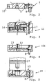
Es zeigt jeweils im Schnitt
- Fig. 1
- die erfindungsgemäße Spannvorrichtung mit nur einem Anschlußmodul
- Fig. 2
- einen Anschlußmodul mit Druckmittelanschlüssen in Form eines Endstückes;
- Fig. 3
- einen Anschlußmodul mit elektrisch gesteuertem Mehrwegeventil in Form eines Zwischenstückes;
- Fig. 4
- einen Anschlußmodul mit elektronischen Mitteln zum Senden und Empfangen von codierten Informationssignalen in Form eines Endstückes;
- Fig. 5
- einen Anschlußmodul mit Endlagendämpfung für den Stellantrieb in Form eines Zwischenstückes;
- Fig. 6
- einen Teil der Spannvorrichtung mit einem Zwischenstück gemäß Fig. 5 und einem Endstück gemäß Fig. 2;
- Fig. 7
- einen Teil der Spannvorrichtung mit einem Zwischenstück gemäß Fig. 3 und einem Endstück gemäß Fig. 2;
- Fig. 8
- das Unterteil der Spannvorrichtung mit zwei Zwischenstücken gemäß Fig. 3 und 5 und einem Endstück gemäß Fig. 2;
- Fig. 9
- das Unterteil der Spannvorrichtung mit einem Zwischenstück gemäß Fig. 3 und einem Endstück gemäß Fig. 4;
- Fig. 10
- das Unterteil der Spannvorrichtung mit zwei Zwischenstücken gemäß Fig. 3 und 5 und einem Endstück gemäß Fig. 4;
- Fig. 11
- das Unterteil der Spannvorrichtung mit im Bereich der Positionsabfrageeinrichtung angeordneten Positionsabfrageanschlüssen;
- Fig. 12
- das Unterteil der Spannvorrichtung gemäß Fig. 11 mit einem Zwischenstück gemäß Fig. 5 und einem einfachen Endstück;
- Fig. 13
- das Unterteil der Spannvorrichtung gemäß Fig. 11 mit zwei Zwischenstücken gemäß Fig. 3 und 5 und einem einfachen Endstück;
- Fig. 14
- das Unterteil der Spannvorrichtung mit im Verbindungsmodul angeordneten elektronischen Mitteln zur Codierung der Signale;
- Fig. 15
- das Unterteil der Spannvorrichtung gemäß Fig. 14 mit dem Modul für die Endlagendämpfung und
- Fig. 16
- eine Spannvorrichtung mit parallel neben ihrem Stellantrieb angeordneten Modulen +(Fig.16A).
- Fig. 1
- the tensioning device according to the invention with only one connection module
- Fig. 2
- a connection module with pressure medium connections in the form of an end piece;
- Fig. 3
- a connection module with an electrically controlled multi-way valve in the form of an intermediate piece;
- Fig. 4
- a connection module with electronic means for sending and receiving coded information signals in the form of an end piece;
- Fig. 5
- a connection module with end position damping for the actuator in the form of an intermediate piece;
- Fig. 6
- part of the tensioning device with an intermediate piece according to FIG. 5 and an end piece according to FIG. 2;
- Fig. 7
- part of the clamping device with an intermediate piece according to FIG. 3 and an end piece according to FIG. 2;
- Fig. 8
- the lower part of the clamping device with two intermediate pieces according to FIGS. 3 and 5 and an end piece according to FIG. 2;
- Fig. 9
- the lower part of the clamping device with an intermediate piece according to FIG. 3 and an end piece according to FIG. 4;
- Fig. 10
- the lower part of the clamping device with two intermediate pieces according to FIGS. 3 and 5 and an end piece according to FIG. 4;
- Fig. 11
- the lower part of the clamping device with position query connections arranged in the area of the position query device;
- Fig. 12
- the lower part of the tensioning device according to FIG 11 with an intermediate piece according to FIG 5 and a simple end piece.
- Fig. 13
- the lower part of the clamping device according to Figure 11 with two intermediate pieces according to Figures 3 and 5 and a simple end piece.
- Fig. 14
- the lower part of the clamping device with electronic means arranged in the connection module for coding the signals;
- Fig. 15
- 14 with the module for the end position damping and
- Fig. 16
- a clamping device with modules + arranged parallel to its actuator (Fig.16A).
Fig. 1 ist die Spannvorrichtung im Schnitt dargestellt,
die in bekannter Weise aus einem druckmittelbetriebenen
mit Druckmittelanschlüssen 2 versehenen Stellantrieb
1(Pneumatik-oder Hydraulikzylinder) besteht, der über ein
linear bewegtes Stellglied 3 und über eine im Kopf 4 der
Spannvorrichtung angeordnete Stellmechanik 5 mit einem
schwenkbar gelagerten Spannarm 6 in Verbindung steht, wobei
dem Stellglied 3 eine nur schematisch angedeutete Positionsabfrageeinrichtung
7 mit elektrischen Positionsabfrageanschlüssen
8(insgesamt nur als Steckdosenanschluß
dargestellt) zugeordnet ist. Die hier sogenannte Schnittstelle
ist mit 9 bezeichnet. Für die Druckmittelzuführung
zwecks Öffnung bzw. Rückstellung des Spannarmes 6 ist am
Stellantrieb 1 ein Druckmittelkanal 10 bei den Ausführungsbeispielen
nach den Fig.1 und 6 bis 15 vorgesehen.1, the clamping device is shown in section,
which in a known manner from a pressure medium operated
actuator provided with pressure
Für eine solche Spannvorrichtung ist nun gemäß erster Lösung
wesentlich, daß an der dem Kopf 4 abgewandten Seite
des Stellantriebes 1 funktional verschiedene, zueinander
aber kompatible Anschlußmodule I bis IV, die quer zur Achse
1' des Stellantriebes orientierte Schnittstelle 9 mindestens
für die Druckmittelanschlüsse 2 bildend, wahlweise
einzeln oder zu mehreren hintereinander angeordnet vorgesehen
sind.For such a clamping device is now according to the first solution
essential that on the side facing away from the
Außerdem ist am Stellantrieb 1 ein Verbindungsmodul V als
Kabelführung für die elektrische Verbindung zwischen der
Positionsabfrageeinrichtung 7 und dem jeweiligen den unterem
Deckelabschluß des Stellantriebes bildenden Modul angeordnet.In addition, a connection module V is on the
In den Fig. 2 bis 5 sind verschiedene sowohl als Endstücke
als auch als Zwischenstücke einzusetzende Anschlußmodule
I-IV dargestellt, wobei der Modul gemäß Fig. 2 dem Anschlußmodul
I nach Fig. 1 entspricht.
Das Zwischenstück bzw. der Modul II gemäß Fig. 3 weist ein
elektrisch gesteuertes Wegeventil 16 zum Öffnen und
Schließen der Druckmittelanschlüsse 2 auf, wobei dessen
elektrischen Anschlüsse 17 zur Steuerung des Wegeventils
16 mit den Abfrageanschlüssen 8 der Schnittstelle 9 verbunden
sind. Der in Form eines Endstückes ausgebildete
Anschlußmodul III in Fig. 4 enthält einen Mikroprozessor
12 umfassende elektronische Mittel 13 (Platine) zum Senden
und Empfangen von codierten Informationssignalen , die mit
einer (nicht dargestellten) Steuer- bzw. Regeleinrichtung
von anderen Spannvorrichtungen in Verbindung stehen. Dieser
Modul gemäß Fig.4 ist für solche Fälle von besonderem
Interesse, in denen mehrere Spannvorrichtungen gewissermaßen
als Computernetzwerk funktionell zu verschalten
sind.2 to 5 show various connection modules I-IV to be used both as end pieces and as intermediate pieces, the module according to FIG. 2 corresponding to the connection module I according to FIG. 1.
The intermediate piece or module II according to FIG. 3 has an electrically controlled
In Fig. 5 ist schließlich ein als Endlagendämpfung 15 für
den Kolben 1" des Stellantrieb 1 dienender Modul IV dargestellt.
Diese an sich bekannte Endlagendämpfung 15 ist
insbesondere bei schnell öffnenden Spannvorrichtungen erforderlich,
um ein "Durchschlagen" des Stellantriebbodens
zu vermeiden.In Fig. 5 is finally as a
In den Fig. 6 bis 10 sind die vorerwähnten Module I bis IV in verschiedenen An- und Zuordnungsmöglichkeiten dargestellt, um die durch die erfindungsgemäße Ausbildung erreichbare Variabilität und Anpaßbarkeit der Spannvorrichtung an unterschiedliche Anschluß- und Funtionserfordernisse zu verdeutlichen.6 to 10 are the aforementioned modules I to IV presented in different arrangement and assignment options, to be achieved by the training according to the invention Variability and adaptability of the clamping device to different connection and function requirements to clarify.
Die im Vergleich zu Fig. 1 gewissermaßen einfachste Ausführungsform
entspricht der in Fig. 11 dargestellten
Spannvorrichtung, deren Ausführungsform lediglich ein in
Form eines Endstückes ausgebildeten Anschlußmodul I mit
Druckmittelanschlüssen 2 aufweist. Die elektrischen Positionsabfrageanschlüsse
8 (lediglich als kleine Steckdose
dargestellt) sind, um den oben erwähnten Verbindungsmodul
V einzusparen, in unmittelbarer Nähe der Positionsabfrageeinrichtung
7 als separater, seitlich angesetzter Modul 11
angeordnet. The simplest embodiment, as it were, compared to FIG. 1
corresponds to that shown in FIG. 11
Clamping device, the embodiment of which is only one in
Form of an end piece formed connection module I with
Has pressure
Die Spannvorrichtung in Fig. 12 entspricht derjenigen in
Fig. 11, allerdings ergänzt um den Modul IV für die Endlagendämpfung.
In Fig. 13 ist außerdem noch eine Spannvorrichtung mit einem
Mehrwegeventil 16 mit eigenen elektrischen Anschlüssen
17 dargestellt, die jedoch auch in einem separaten, außen
angesetzten Modul 11' vorgesehen sein können.
Schließlich sind in Fig. 14 und 15 Spannvorrichtungen dargestellt,
bei denen die einen Mikroprozessor 12 aufweisenden
elektronischen Mittel 13 im vorerwähnten Verbindungsmodul
V' mit angeordnet sind.
Der Fig. 14 als Verlängerung dienende Anschlußmodul I'
entspricht funktionell dem Modul I. Dieser Anschlußmodul
I' ist aber, wie vorerwähnt, sowohl als Zwischenstück als
auch als Endstück einsetzbar.The tensioning device in FIG. 12 corresponds to that in FIG. 11, but supplemented by module IV for the end position damping.
13 also shows a tensioning device with a
Finally, FIGS. 14 and 15 show clamping devices in which the electronic means 13, which have a
The connection module I 'serving as an extension corresponds functionally to module I. This connection module I', however, as mentioned above, can be used both as an intermediate piece and as an end piece.
Nicht besonders dargestellt sind sinngemäß kompatible an -
oder zwischensetzbare Module, mit denen bspw. bei entsprechend
installierter Stellungssensorik alle Winkelstellungen
des Spannarmes 6 verarbeitet werden können oder, wenn
es sich um Spannvorrichtungen handelt, die außer mit ihrem
Druckmittelstellantrieb auch per Handhebel verstellt werden
können, also Module, die bei beabsichtigter Handbetätigung
dafür sorgen, daß diese auch tatsächlich bewirkt
werden kann.The following are not particularly depicted:
or interposed modules with which, for example
installed position sensors all angular positions
of the
Wie einleitend erwähnt, ist der axial orientierte Anbau
der Module am unteren Ende des Stellantriebes 1 (abgesehen
vom evtl. notwendigen Dämpfungsmodul IV) nicht zwingend,
d.h., die Zuordnung der Module kann auch parallel unmittelbar
neben dem Stellantrieb erfolgen , wie dies bspw.
in Fig. 16 verdeutlicht ist. Für eine solche Zuordnung ist
wesentlich, daß parallel zur Achse 1' des Stellantriebes 1
ebenfalls funtional verschiedene, zueinander kompatible
Anschlußmodule angeordnet sind, wobei die Schnittstelle 9
für die Druckmittelanschlüsse des Stellantriebes 1 zur Modulanordnungsseite
hin orientiert angeordnet ist.As mentioned in the introduction, the axially oriented extension is
of the modules at the lower end of the actuator 1 (apart from
of the possibly required damping module IV) is not mandatory,
i.e. the assignment of the modules can also be done directly in parallel
next to the actuator, such as this.
is illustrated in Fig. 16. For such an assignment is
essential that parallel to the axis 1 'of the actuator 1st
also functionally different, mutually compatible
Connection modules are arranged, the
Sofern nicht ein Druckmittelführungskanal 10', wie vorerläutert,
für die Spannarmrückstellung vorgesehen ist,
d.h., der Druckmittelanschluß für die Spannarm- bzw. Kolbenrückstellung
sich am oberen Abschluß 20 des Stellantriebes
1 befindet, ist ein Adapter 21 vorgesehen, der
entsprechende Druckmittelführungskanäle 10' enthält, die
mit dem angesetzten Ventilmodul II' in funktionsgemäßer
Verbindung stehen. Zu diesem Ventilmodul II' gehört auch
ein Elektromagnetteil II" für die Ventilsteuerung, über
dem der Elektronikmodul III' sitzt, der seinerseits, wie
bspw. dargestellt, über einen Kabelanschluß 22 mit den
Endstellungsabfrageeinrichtungen 7 verbunden ist. Bezüglich
dieser Endstellungsabfrageeinrichtung 7, die keiner
näheren Erläuterung bedarf, da an sich bekannt, sei darauf
hingewiesen, daß es sich dabei auch um Abfrageeinrichtungen
handeln kann, mit denen nicht nur die Endstellungen
sondern auch alle Zwischenstellungen des Spanarmes 6 abgefragt
werden können. Statt des dargestellten Kabelanschlusses
22 kann der Elektronikmodul III' unter Wegfall
des Anschlusses 11' der Abfrageeinrichtung 7 auch so ausgebildet
sein, daß dieser mit einem Fortsatz 26 direkt mit
dem Kopf 4 verbindbar ist (siehe Fig.16A)
Der Elektronikmodul III' ist ferner mit einem Stecker 23
für eine sogenannte BUS-Verbindung versehen und kann auch
einen zusätzlichen Stecker 24 aufweisen, um bspw. Werkstücksensoren
anschließen zu können, die anzeigen, daß
sich ein festzuspannendes Werkstück in Stellung befindet,
um festgespannt zu werden. Nicht dargestellt ist am Ventilmodul
II' der Anschluß für die Druckmittelzufuhr.
Der untere Abschlußdeckel 25 des Stellantriebes 1 steht
natürlich auch hier wie bei der vorbeschriebenen Ausführungsformen
nach den Fig. 1 bis 15 in lösbarere Verbindung
mit dem eigentlichen Zylinder des Stellantriebes 1,
um diesen, falls erforderlich, gegen einen Dämpfungsmodul
im Sinne der Fig.5 austauschen zu können.Unless a pressure medium guide channel 10 ', as explained above, is provided for the tension arm reset, ie the pressure medium connection for the tension arm or piston reset is located at the
The electronics module III 'is also provided with a
The
Sofern hier und auch in den Ansprüchen von Modulen I bis
IV bzw. II',III' die Rede ist, soll dies keine Einschränkung
hinsichtlich der tatsächlich anzuordnenden Anzahl von
Modulen darstellen.
Im übrigen sei noch abschließend darauf hingewiesen, daß
unter "Kompatibilität" der Module zu verstehen ist nicht
nur deren mechanische Zusammenfüg- und Fixierbarkeit, sondern
auch deren passende Zuordnung von Kanälen und Leitungsführungen.Insofar as here and also in the claims of modules I to IV or II ', III', this should not constitute a restriction with regard to the number of modules actually to be arranged.
In addition, it should finally be pointed out that the "compatibility" of the modules is not only to be understood as their mechanical assembly and fixability, but also their appropriate assignment of channels and cable routing.
Claims (14)
- A clamping device for clamping of workpieces, comprising a pressure-fluid-operated actuator (1) having an interface (9) for pressure fluid and electrical connections (2,8) which (actuator), via a linearly moved control element (3) and via an adjusting mechanism (5) disposed in the head (4) of the clamping device, is in communication with a pivotally arranged clamping arm (6), wherein a position sensor (7) having electrical position sensor terminals (8) is associated to the control element (3),
characterized in that arranged in series, optionally alone or combined, on the side of the actuator (1) facing away from the head (4) are functionally different yet compatible connecting modules (I through IV) in a manner forming the interface (9) at least for the pressure fluid connections (2) and being oriented transverse of the axis (1') of the actuator. - A clamping device according to claim 1,
characterized in that the connecting modules are formed as end section- or intermediate section-modules and that, in addition, a connecting module (V, V') is provided. - A claming device according to claim 2,
characterized in that the connecting module (V, V') is arranged on the actuator (1) as a wire guide for the electrical connection between the position sensor (7) and one of the connecting modules (I through IV). - A clamping device according to claim 3,
characterized in that arranged in the connecting module (11, V) are electronic means (13) for transmitting and receiving encoded information signals. - A clamping device according to claim 4,
characterized in that the electronic means (13) arranged in the connecting module (11, V) are in communication with an electric connection (14) externally arranged on the connecting module (11). - A clamping device according to claim 2,
characterized in that the end-section module (I) includes the pressure fluid terminals (2). - A clamping device according to claim (2),
characterized in that the end-section module (III) containing the pressure-fluid terminals (2) comprises electronic means (13). - A clamping device according to claims 6 or 7,
characterized in that disposed between the end-section module and the actuator (1) is at least one module designed as an intermediate section. - A claming device according to claim 8,
characterized in that the intermediate section is designed as an end position attenuator module (IV) for the actuator (1). - A clamping device according to claim 8,
characterized in that disposed within the intermediate-section module (II) is at least one electrically controlled way-valve (16) for opening and closing the pressure-fluid terminals (2), with the electrical connections (17) thereof being connected to the sensor terminals (8). - A clamping device for clamping workpieces, comprising a pressure-fluid-operated actuator (1) having an interface (9) for pressure-fluid- and electrical connections (2,8) which, via a linearly moved control element (3) and via an adjusting mechanism (5) disposed in the head (4) of the clamping device is in communication with a pivotally disposed clamping arm (6), wherein a position sensor (7) having electrical position sensor terminals is associated to the control element (3),
characterized in that functionally different yet compatible connecting modules (II' through IV') are arranged, optionally alone or combined, substantially in parallel to the axis (1') of the actuator (1) in side-by-side relationship therewith, and that the interface (9) for the pressure fluid connections (2) of the actuator (1) is arranged in a manner oriented toward the module mounting side. - A clamping device according to claim 11,
characterized in that the connecting modules (II' through IV') are arranged on an adapter (21) containing pressure fluid-carrying passageways (10') that are in communication with pressure fluid connections (2) provided in the upper and lower closure lid (20,25) of the actuator (1). - A clamping device according to claims 11 or 12,
characterized in that the bottom closure lid (25) of the actuator (1) can be replaced by a module (IV) designed as an end position attenuator (15). - A clamping device according to claims 4 and 7,
characterized in that the electronic means (13) comprise a microprocessor (12).
Applications Claiming Priority (2)
| Application Number | Priority Date | Filing Date | Title |
|---|---|---|---|
| DE19801433A DE19801433A1 (en) | 1998-01-16 | 1998-01-16 | Jig |
| DE19801433 | 1998-01-16 |
Publications (3)
| Publication Number | Publication Date |
|---|---|
| EP0930130A2 EP0930130A2 (en) | 1999-07-21 |
| EP0930130A3 EP0930130A3 (en) | 2001-02-07 |
| EP0930130B1 true EP0930130B1 (en) | 2003-06-11 |
Family
ID=7854788
Family Applications (1)
| Application Number | Title | Priority Date | Filing Date |
|---|---|---|---|
| EP99100659A Expired - Lifetime EP0930130B1 (en) | 1998-01-16 | 1999-01-14 | Clamping device |
Country Status (3)
| Country | Link |
|---|---|
| EP (1) | EP0930130B1 (en) |
| DE (2) | DE19801433A1 (en) |
| ES (1) | ES2195453T3 (en) |
Families Citing this family (7)
| Publication number | Priority date | Publication date | Assignee | Title |
|---|---|---|---|---|
| DE29903825U1 (en) | 1999-03-03 | 1999-05-27 | Festo AG & Co, 73734 Esslingen | Jig |
| DE10052857A1 (en) * | 2000-10-24 | 2002-05-02 | Sta Co Mettallerzeugnisse Gmbh | Workpiece clamping device which can be actuated by an electric motor |
| BR0110179A (en) * | 2001-02-22 | 2003-03-05 | Festo Ag & Co | Fluid force cylinder |
| DE20209237U1 (en) * | 2002-06-13 | 2002-09-19 | DE-STA-Co Metallerzeugnisse GmbH, 61440 Oberursel | Toggle clamp |
| DE20307245U1 (en) * | 2003-05-08 | 2003-08-07 | DBT GmbH, 44534 Lünen | Return valve for a hydraulic cylinder has a connector (5-9) which attached to the valve housing (3) in the hydraulic cylinder (2) in a fixed position parallel to the axis (16) of the cylinder |
| PL202250B1 (en) * | 2003-05-08 | 2009-06-30 | Dbt Gmbh | Hydraulic valve, particularly non-return valve and hydraulic support, particularly hydraulic prop |
| WO2018202290A1 (en) * | 2017-05-03 | 2018-11-08 | Festo Ag & Co. Kg | Electropneumatic controller and process control device equipped therewith |
Family Cites Families (8)
| Publication number | Priority date | Publication date | Assignee | Title |
|---|---|---|---|---|
| DE3403961C2 (en) * | 1984-02-04 | 1987-01-29 | Josef Gerhard 4030 Ratingen Tünkers | Pneumatically or hydraulically operated toggle lever clamping device for clamping body parts |
| DE8714390U1 (en) * | 1987-10-29 | 1989-03-02 | De-Sta-Co Metallerzeugnisse Gmbh, 6000 Frankfurt | Clamping device |
| DE8811579U1 (en) * | 1988-09-13 | 1990-01-11 | De-Sta-Co Metallerzeugnisse Gmbh, 6000 Frankfurt | Clamping device |
| DE9016781U1 (en) * | 1990-12-12 | 1992-04-09 | De-Sta-Co Metallerzeugnisse Gmbh, 6000 Frankfurt | Clamping device |
| DE9105755U1 (en) * | 1991-05-08 | 1991-06-27 | De-Sta-Co Metallerzeugnisse Gmbh, 6000 Frankfurt | Clamping device |
| ES2067279T3 (en) * | 1991-09-03 | 1995-03-16 | Sta Co Mettallerzeugnisse Gmbh | FIXING DEVICE. |
| DE29519232U1 (en) * | 1995-12-05 | 1996-04-04 | Tünkers Maschinenbau GmbH, 40880 Ratingen | Toggle clamp device |
| DE19616441C1 (en) * | 1996-04-25 | 1997-06-26 | Tuenkers Maschinenbau Gmbh | Toggle joint clamping device for vehicle bodywork, with grip head |
-
1998
- 1998-01-16 DE DE19801433A patent/DE19801433A1/en not_active Ceased
-
1999
- 1999-01-14 EP EP99100659A patent/EP0930130B1/en not_active Expired - Lifetime
- 1999-01-14 DE DE59905895T patent/DE59905895D1/en not_active Expired - Fee Related
- 1999-01-14 ES ES99100659T patent/ES2195453T3/en not_active Expired - Lifetime
Also Published As
| Publication number | Publication date |
|---|---|
| ES2195453T3 (en) | 2003-12-01 |
| EP0930130A3 (en) | 2001-02-07 |
| EP0930130A2 (en) | 1999-07-21 |
| DE19801433A1 (en) | 1999-07-22 |
| DE59905895D1 (en) | 2003-07-17 |
Similar Documents
| Publication | Publication Date | Title |
|---|---|---|
| DE4004834C2 (en) | Valve assembly | |
| DE4230414C2 (en) | Electro-pneumatic control device | |
| EP1013940B1 (en) | Valve arrangement | |
| WO1994004831A1 (en) | Electro-pneumatic control device | |
| EP0803653A1 (en) | Pneumatic commandassembly | |
| EP3296602B1 (en) | Fluid distribution apparatus | |
| EP0796519A1 (en) | Control device, in particular for actuating valves | |
| EP0930130B1 (en) | Clamping device | |
| EP1710447A1 (en) | Electro-fluidic control device | |
| DE3708902C2 (en) | Control unit for electro-hydraulic expansion controls | |
| WO1995002770A1 (en) | Valve station | |
| DE9211109U1 (en) | Electro-pneumatic control device | |
| EP0629783B1 (en) | Combined control of pneumatic and hydraulic valves | |
| EP2354563B1 (en) | Valve assembly | |
| EP0713980B1 (en) | A driving device | |
| DE10003961A1 (en) | Clamp with integrated control valve | |
| EP0359073A2 (en) | Clamping device | |
| EP1251283B1 (en) | Kit for making a fluid control device | |
| DE10203792A1 (en) | Pneumatic valve unit for controlling packaging systems, has parallel electrical lines corresponding to number of multiway valves on contact surface with insulation removed at defined points to form valve contact fields | |
| EP1284371B1 (en) | Matrix assembly of valves | |
| DE102010031922A1 (en) | Valve unit e.g. bistable valve unit, has control valve modules equipped with contact units, where connection end of one of contact units is arranged at growing surface of one control valve module | |
| DE4005429A1 (en) | Agricultural harvesting self loader - has number of hydraulic devices controlled by servo motor and series of valves | |
| AT405464B (en) | Pneumatic actuating arrangement | |
| EP1345009B1 (en) | Hydraulic assembly and connector strip | |
| DE9318648U1 (en) | Control device for electromagnetically piloted valve modules |
Legal Events
| Date | Code | Title | Description |
|---|---|---|---|
| PUAI | Public reference made under article 153(3) epc to a published international application that has entered the european phase |
Free format text: ORIGINAL CODE: 0009012 |
|
| AK | Designated contracting states |
Kind code of ref document: A2 Designated state(s): DE ES FR GB IT SE |
|
| AX | Request for extension of the european patent |
Free format text: AL;LT;LV;MK;RO;SI |
|
| PUAL | Search report despatched |
Free format text: ORIGINAL CODE: 0009013 |
|
| AK | Designated contracting states |
Kind code of ref document: A3 Designated state(s): AT BE CH CY DE DK ES FI FR GB GR IE IT LI LU MC NL PT SE |
|
| AX | Request for extension of the european patent |
Free format text: AL;LT;LV;MK;RO;SI |
|
| 17P | Request for examination filed |
Effective date: 20010719 |
|
| AKX | Designation fees paid |
Free format text: DE ES FR GB IT SE |
|
| GRAH | Despatch of communication of intention to grant a patent |
Free format text: ORIGINAL CODE: EPIDOS IGRA |
|
| GRAH | Despatch of communication of intention to grant a patent |
Free format text: ORIGINAL CODE: EPIDOS IGRA |
|
| GRAA | (expected) grant |
Free format text: ORIGINAL CODE: 0009210 |
|
| AK | Designated contracting states |
Designated state(s): DE ES FR GB IT SE |
|
| REG | Reference to a national code |
Ref country code: GB Ref legal event code: FG4D Free format text: NOT ENGLISH |
|
| REG | Reference to a national code |
Ref country code: SE Ref legal event code: TRGR |
|
| GBT | Gb: translation of ep patent filed (gb section 77(6)(a)/1977) | ||
| REF | Corresponds to: |
Ref document number: 59905895 Country of ref document: DE Date of ref document: 20030717 Kind code of ref document: P |
|
| ET | Fr: translation filed | ||
| PLBE | No opposition filed within time limit |
Free format text: ORIGINAL CODE: 0009261 |
|
| STAA | Information on the status of an ep patent application or granted ep patent |
Free format text: STATUS: NO OPPOSITION FILED WITHIN TIME LIMIT |
|
| 26N | No opposition filed |
Effective date: 20040312 |
|
| PG25 | Lapsed in a contracting state [announced via postgrant information from national office to epo] |
Ref country code: IT Free format text: LAPSE BECAUSE OF NON-PAYMENT OF DUE FEES Effective date: 20050114 |
|
| PGFP | Annual fee paid to national office [announced via postgrant information from national office to epo] |
Ref country code: DE Payment date: 20061213 Year of fee payment: 9 |
|
| PGFP | Annual fee paid to national office [announced via postgrant information from national office to epo] |
Ref country code: FR Payment date: 20061215 Year of fee payment: 9 |
|
| PGFP | Annual fee paid to national office [announced via postgrant information from national office to epo] |
Ref country code: GB Payment date: 20070104 Year of fee payment: 9 |
|
| PGFP | Annual fee paid to national office [announced via postgrant information from national office to epo] |
Ref country code: SE Payment date: 20070118 Year of fee payment: 9 |
|
| EUG | Se: european patent has lapsed | ||
| GBPC | Gb: european patent ceased through non-payment of renewal fee |
Effective date: 20080114 |
|
| PG25 | Lapsed in a contracting state [announced via postgrant information from national office to epo] |
Ref country code: DE Free format text: LAPSE BECAUSE OF NON-PAYMENT OF DUE FEES Effective date: 20080801 |
|
| REG | Reference to a national code |
Ref country code: FR Ref legal event code: ST Effective date: 20081029 |
|
| PG25 | Lapsed in a contracting state [announced via postgrant information from national office to epo] |
Ref country code: GB Free format text: LAPSE BECAUSE OF NON-PAYMENT OF DUE FEES Effective date: 20080114 |
|
| PG25 | Lapsed in a contracting state [announced via postgrant information from national office to epo] |
Ref country code: SE Free format text: LAPSE BECAUSE OF NON-PAYMENT OF DUE FEES Effective date: 20080115 |
|
| PG25 | Lapsed in a contracting state [announced via postgrant information from national office to epo] |
Ref country code: FR Free format text: LAPSE BECAUSE OF NON-PAYMENT OF DUE FEES Effective date: 20080131 |
|
| PGFP | Annual fee paid to national office [announced via postgrant information from national office to epo] |
Ref country code: IT Payment date: 20070627 Year of fee payment: 9 |
|
| PGRI | Patent reinstated in contracting state [announced from national office to epo] |
Ref country code: IT Effective date: 20110616 |
|
| PGFP | Annual fee paid to national office [announced via postgrant information from national office to epo] |
Ref country code: ES Payment date: 20111207 Year of fee payment: 14 |
|
| PGRI | Patent reinstated in contracting state [announced from national office to epo] |
Ref country code: IT Effective date: 20110616 |
|
| REG | Reference to a national code |
Ref country code: ES Ref legal event code: FD2A Effective date: 20140321 |
|
| PG25 | Lapsed in a contracting state [announced via postgrant information from national office to epo] |
Ref country code: ES Free format text: LAPSE BECAUSE OF NON-PAYMENT OF DUE FEES Effective date: 20130115 |