EP0889192B1 - Power window apparatus - Google Patents
Power window apparatus Download PDFInfo
- Publication number
- EP0889192B1 EP0889192B1 EP98305047A EP98305047A EP0889192B1 EP 0889192 B1 EP0889192 B1 EP 0889192B1 EP 98305047 A EP98305047 A EP 98305047A EP 98305047 A EP98305047 A EP 98305047A EP 0889192 B1 EP0889192 B1 EP 0889192B1
- Authority
- EP
- European Patent Office
- Prior art keywords
- window
- switch
- relay
- contacts
- lowering
- Prior art date
- Legal status (The legal status is an assumption and is not a legal conclusion. Google has not performed a legal analysis and makes no representation as to the accuracy of the status listed.)
- Expired - Lifetime
Links
Images


Classifications
-
- B—PERFORMING OPERATIONS; TRANSPORTING
- B60—VEHICLES IN GENERAL
- B60J—WINDOWS, WINDSCREENS, NON-FIXED ROOFS, DOORS, OR SIMILAR DEVICES FOR VEHICLES; REMOVABLE EXTERNAL PROTECTIVE COVERINGS SPECIALLY ADAPTED FOR VEHICLES
- B60J7/00—Non-fixed roofs; Roofs with movable panels, e.g. rotary sunroofs
- B60J7/02—Non-fixed roofs; Roofs with movable panels, e.g. rotary sunroofs of sliding type, e.g. comprising guide shoes
- B60J7/04—Non-fixed roofs; Roofs with movable panels, e.g. rotary sunroofs of sliding type, e.g. comprising guide shoes with rigid plate-like element or elements, e.g. open roofs with harmonica-type folding rigid panels
- B60J7/057—Driving or actuating arrangements e.g. manually operated levers or knobs
- B60J7/0573—Driving or actuating arrangements e.g. manually operated levers or knobs power driven arrangements, e.g. electrical
-
- E—FIXED CONSTRUCTIONS
- E05—LOCKS; KEYS; WINDOW OR DOOR FITTINGS; SAFES
- E05F—DEVICES FOR MOVING WINGS INTO OPEN OR CLOSED POSITION; CHECKS FOR WINGS; WING FITTINGS NOT OTHERWISE PROVIDED FOR, CONCERNED WITH THE FUNCTIONING OF THE WING
- E05F15/00—Power-operated mechanisms for wings
- E05F15/60—Power-operated mechanisms for wings using electrical actuators
- E05F15/603—Power-operated mechanisms for wings using electrical actuators using rotary electromotors
- E05F15/665—Power-operated mechanisms for wings using electrical actuators using rotary electromotors for vertically-sliding wings
- E05F15/689—Power-operated mechanisms for wings using electrical actuators using rotary electromotors for vertically-sliding wings specially adapted for vehicle windows
- E05F15/695—Control circuits therefor
-
- E—FIXED CONSTRUCTIONS
- E05—LOCKS; KEYS; WINDOW OR DOOR FITTINGS; SAFES
- E05F—DEVICES FOR MOVING WINGS INTO OPEN OR CLOSED POSITION; CHECKS FOR WINGS; WING FITTINGS NOT OTHERWISE PROVIDED FOR, CONCERNED WITH THE FUNCTIONING OF THE WING
- E05F15/00—Power-operated mechanisms for wings
- E05F15/40—Safety devices, e.g. detection of obstructions or end positions
-
- E—FIXED CONSTRUCTIONS
- E05—LOCKS; KEYS; WINDOW OR DOOR FITTINGS; SAFES
- E05F—DEVICES FOR MOVING WINGS INTO OPEN OR CLOSED POSITION; CHECKS FOR WINGS; WING FITTINGS NOT OTHERWISE PROVIDED FOR, CONCERNED WITH THE FUNCTIONING OF THE WING
- E05F15/00—Power-operated mechanisms for wings
- E05F15/70—Power-operated mechanisms for wings with automatic actuation
- E05F15/72—Power-operated mechanisms for wings with automatic actuation responsive to emergency conditions, e.g. fire
-
- E—FIXED CONSTRUCTIONS
- E05—LOCKS; KEYS; WINDOW OR DOOR FITTINGS; SAFES
- E05Y—INDEXING SCHEME ASSOCIATED WITH SUBCLASSES E05D AND E05F, RELATING TO CONSTRUCTION ELEMENTS, ELECTRIC CONTROL, POWER SUPPLY, POWER SIGNAL OR TRANSMISSION, USER INTERFACES, MOUNTING OR COUPLING, DETAILS, ACCESSORIES, AUXILIARY OPERATIONS NOT OTHERWISE PROVIDED FOR, APPLICATION THEREOF
- E05Y2400/00—Electronic control; Electrical power; Power supply; Power or signal transmission; User interfaces
- E05Y2400/10—Electronic control
- E05Y2400/44—Sensors not directly associated with the wing movement
- E05Y2400/447—Moisture or submergence sensors
-
- E—FIXED CONSTRUCTIONS
- E05—LOCKS; KEYS; WINDOW OR DOOR FITTINGS; SAFES
- E05Y—INDEXING SCHEME ASSOCIATED WITH SUBCLASSES E05D AND E05F, RELATING TO CONSTRUCTION ELEMENTS, ELECTRIC CONTROL, POWER SUPPLY, POWER SIGNAL OR TRANSMISSION, USER INTERFACES, MOUNTING OR COUPLING, DETAILS, ACCESSORIES, AUXILIARY OPERATIONS NOT OTHERWISE PROVIDED FOR, APPLICATION THEREOF
- E05Y2900/00—Application of doors, windows, wings or fittings thereof
- E05Y2900/50—Application of doors, windows, wings or fittings thereof for vehicles
- E05Y2900/53—Type of wing
- E05Y2900/542—Roof panels
-
- E—FIXED CONSTRUCTIONS
- E05—LOCKS; KEYS; WINDOW OR DOOR FITTINGS; SAFES
- E05Y—INDEXING SCHEME ASSOCIATED WITH SUBCLASSES E05D AND E05F, RELATING TO CONSTRUCTION ELEMENTS, ELECTRIC CONTROL, POWER SUPPLY, POWER SIGNAL OR TRANSMISSION, USER INTERFACES, MOUNTING OR COUPLING, DETAILS, ACCESSORIES, AUXILIARY OPERATIONS NOT OTHERWISE PROVIDED FOR, APPLICATION THEREOF
- E05Y2900/00—Application of doors, windows, wings or fittings thereof
- E05Y2900/50—Application of doors, windows, wings or fittings thereof for vehicles
- E05Y2900/53—Type of wing
- E05Y2900/55—Windows
Definitions
- the present invention relates to power window apparatuses, and more specifically, to a power window apparatus which allows a door window to be opened by an operation of a window lowering switch if a car drops into water for some reason.
- Fig. 5 is a circuit configuration of a main part of such a conventional power window apparatus.
- the power window apparatus is formed of a window raising switch 21, a window raising relay 22 and its contacts 22 1 , a window lowering switch 23, a window lowering relay 24 and its contacts 24 1 , an automatic raising switch 25, an automatic lowering switch 26, a window opening and closing motor 27, a control integrated circuit (IC) 28, and a car power source (battery) 29.
- the window raising switch 21 and the window raising relay 22 are connected in series, and the window lowering switch 23 and the window lowering relay 24 are also connected in series.
- a connection point "a" between the window raising switch 21 and the window raising relay 22 is connected to a pin 1 ⁇ of the control integrated circuit 28.
- a connection point "b” between the window lowering switch 23 and the window lowering relay 24 is connected to a pin 2 ⁇ of the control integrated circuit 28.
- the automatic raising switch 25 is connected between the connection point "a” and a pin 3 ⁇ of the control integrated circuit 28.
- the automatic lowering switch 26 is connected between the connection point "b” and the pin 3 ⁇ of the control integrated circuit 28.
- a movable contact is connected to one end of the window opening and closing motor 27, one fixed contact is connected to the car power source 29, and the other fixed contact is connected to the ground.
- a movable contact is connected to the other end of the window opening and closing motor 27, one fixed contact is connected to the car power source 29, and the other fixed contact is connected to the ground.
- a pin 4 ⁇ of the control integrated circuit 28 is connected to the window raising relay 22, a pin 5 ⁇ is connected to the window lowering relay 24, and a pin 6 ⁇ is connected to the car power source 29.
- the power window apparatus configured as described above will roughly operate in the following way.
- the window raising switch 21 When the driver operates the automatic raising switch 25, its contacts are closed, the window raising switch 21 is operated at the same time, and its contacts also become closed. Since the contacts of the window raising switch 21 are closed, the car power source 29 drives the window raising relay 22. In the same way as when the window raising switch 21 is operated as described above, the window opening and closing motor 27 rotates in one direction, and thereby the window moves in the raising direction (closing direction). Since the contacts of the window raising switch 21 are closed and those of the automatic raising switch 25 are closed, the voltage obtained at the connection point "a" is supplied to the pins 1 ⁇ and 3 ⁇ of the control integrated circuit 28.
- the voltage of the car power source 29 is latched and output from the pin 4 ⁇ of the control integrated circuit 28, and sent to the window raising relay 22. Therefore, even if the operation of the automatic raising switch 25 is stopped, its contacts become open, the operation of the window raising switch 21 is stopped at the same time, and its contacts become open. Since the voltage output from the pin 4 ⁇ has been latched, the window raising relay 22 continues being driven, the window opening and closing motor 27 rotates in one direction, and thereby the window continues moving in the raising direction (closing direction). The window continues moving in the raising direction (closing direction) until the window is fully closed.
- the window lowering switch 23 is operated at the same time, and its contacts also become closed.
- the window opening and closing motor 27 rotates in the other direction, and thereby the window moves in the lowering direction (opening direction). Since the contacts of the window lowering switch 23 are closed and those of the automatic lowering switch 26 are closed, the voltage obtained at the connection point "b" is supplied to the pins 2 ⁇ and 3 ⁇ of the control integrated circuit 28. In response to the supply of this voltage, the voltage of the car power source 29 is latched and output from the pin 5 ⁇ of the control integrated circuit 28, and sent to the window lowering relay 24.
- the window lowering relay 24 continues being driven, the window opening and closing motor 27 rotates in the other direction, and thereby the window continues moving in the lowering direction (opening direction). The window continues moving in the lowering direction (opening direction) until the window is fully opened.
- Another object of the present invention is to provide a power window apparatus which allows a window to automatically open without a switch operation if the card drops into water and is submerged in water.
- a power window apparatus comprising: a first series circuit with a first switch and a first relay, connected between a car power source and a ground; a second series circuit with a second switch and a second relay, connected between the car power source and the ground; and a motor connected to one of the contacts of the first relay at one side and to one of the contacts of the second relay in the other side, rotated in one direction due to switching of the contacts in the first relay when the first switch is operated to raise a window, and rotated in the other direction due to switching of the contacts in the second relay when the second switch is operated to lower the window, characterised in that the first switch and the second switch each have one circuit with two contacts, and the fixed contacts which are switched when the first switch or the second switch is not operated are grounded through minute gaps.
- a power window apparatus including: a first series circuit with a first switch and a first relay, connected between a car power source and a ground; a second series circuit with a second switch and a second relay, connected between the car power source and the ground; and a motor connected to one of the contacts of the first relay at one side and to one of the contacts of the second relay in the other side, rotated in one direction due to switching of the contacts in the first relay when the first switch is operated to raise a window, and rotated in the other direction due to switching of the contacts in the second relay when the second switch is operated to lower the window, characterised in that the first switch and the second switch each have one circuit with two contacts, and the fixed contacts which are switched when the first switch or the second switch is not operated are connected to the car power source.
- the first switch and the second switch are disposed is submerged in water, and water connects the contacts of the first switch and also connects those of the second switch as resistors allowing continuity, since a current caused by the voltage of the car power source flows into the ground through the water serving as resistors allowing continuity and the movable contacts switched to the fixed contacts connected to the ground, the voltage of the car power source is not applied to the first relay or the second relay. Neither the first relay nor the second relay is operated due to connection by water serving as resistors allowing continuity.
- a power window apparatus including: a first series circuit with a first switch and a first relay, connected between a car power source and a ground; a second series circuit with a second switch and a second relay, connected between the car power source and the ground; and a motor connected to one of the contacts of the first relay at one side and to one of the contacts of the second relay in the other side, rotated in one direction due to switching of the contacts in the first relay when the first switch is operated to raise a window, and rotated in the other direction due to switching of the contacts in the second relay when the second switch is operated to lower the window, wherein the first switch has one circuit with two contacts, the fixed contact which is switched when the first switch is not operated is grounded, and the second switch is open when not operated.
- the voltage of the car power source is not applied to the first relay and the first relay is not operated due to connection by water serving as a resistor allowing continuity.
- the voltage of the car power source is applied to the second relay through the water at the second switch to drive the second relay. The contacts of the second relay are switched, the motor is rotated in the other direction, and the window is automatically opened.
- Fig. 1 is a circuit diagram showing a circuit configuration of a main section of a power window apparatus according to a first embodiment of the present invention.
- Fig. 2 is a circuit diagram showing another configuration of a window raising switch and a window lowering switch.
- Fig. 3 is a circuit diagram showing a circuit configuration in a case in which the window raising switch is connected to the ground side of a window raising relay and the window lowering switch is connected to the ground side of the window lowering relay.
- Fig. 4 is a circuit diagram showing a circuit configuration of a main section of a power window apparatus according to a second embodiment of the present invention.
- Fig. 5 is a circuit diagram showing a circuit configuration of a main section of a conventional power window apparatus.
- Fig. 1 is a circuit diagram showing a circuit configuration of a main part of a power window apparatus according to a first embodiment of the present invention.
- the power window apparatus of the first embodiment is formed of a window raising switch (a first switch) 1, a window raising relay (a first relay) 2 and its contacts 2 1 , a window lowering switch (a second switch) 3, a window lowering relay (a second relay) 4 and its contacts 4 1 , an automatic raising switch 5, an automatic lowering switch 6, a first reverse-current-blocking diode 7, a second reverse-current-blocking diode 8, a window opening and closing motor 9, a control integrated circuit (IC) 10, and a car power source (battery) 11.
- a window raising switch a first switch
- a window raising relay a first relay
- a second switch 3
- a window lowering relay a second relay
- a first series circuit formed of the window raising switch 1, the first reverse-current-blocking diode 7, and the window raising relay 2, and a second series circuit formed of the window lowering switch 3, the second reverse-current-blocking diode 8, and the window lowering relay 4 are connected.
- the window raising switch 1 and the window lowering switch 2 each have one circuit with two contacts. Their normally closed, fixed contacts are grounded, their normally open, fixed contacts are connected to the car power source 11, and their movable contacts are connected to the first reverse-current-blocking diode 7 and the second reverse-current-blocking diode 8.
- a connection point "a" between the window raising relay 2 and the first reverse-current-blocking diode 7 is connected to a port 1 ⁇ of the control integrated circuit 10.
- a connection point "b” between the window lowering relay 4 and the second reverse-current-blocking diode 8 is connected to a port 2 ⁇ of the control integrated circuit 10.
- One end of the automatic raising switch 5 is connected to the connection point "a” and the other end is connected to a port 3 ⁇ of the control integrated circuit 10.
- One end of the automatic lowering switch 6 is connected to the connection point "b” and the other end is connected to a port 3 ⁇ of the control integrated circuit 10.
- a movable contact is connected to one end of the window opening and closing motor 9, one fixed contact is connected to the car power source 11, and the other fixed contact is connected to the ground.
- a movable contact is connected to the other end of the window opening and closing motor 9, one fixed contact is connected to the car power source 11, and the other fixed contact is connected to the ground.
- a port 4 ⁇ of the control integrated circuit 10 is connected to the connection point between the window raising relay 2 and the first reverse-current-blocking diode 7, a port 5 ⁇ is connected to the connection point between the window lowering relay 4 and the second reverse-current-blocking diode 8, and a port 6 ⁇ is connected to the car power source 11.
- the power window apparatus configured as described above according to the first embodiment will roughly operate in the following way.
- the window raising switch 1 When a car driver operates the window raising switch 1, its contacts are switched from the normally closed, fixed contact side (shown) to the normally open, fixed contact side.
- the voltage of the car power source 11 is applied to the window raising relay 2 through the window raising switch 1 and the first reverse-current-blocking diode 7 to drive the window raising relay 2. Then, the contacts 2 1 of the window raising relay 2 are switched from the connection condition shown in the figure to the other connection condition.
- the voltage of the car power source 11 is applied to the window opening and closing motor 9 to rotate the motor 9 in one direction. With the rotation of the window opening and closing motor 9 in one direction, the window is raised, namely, the window is moved in the closing direction.
- the window raising switch 1 When the operation of the window raising switch 1 is stopped, its contacts are switched to the normally-closed, fixed contact side (shown). Since the voltage of the car power source 11 is blocked by the window raising switch 1 and the driving of the window raising relay 2 is stopped, the window opening and closing motor 9 is stopped rotating. The raising of the window is stopped, and the window is held at that position.
- the driver When the driver operates the window lowering switch 3, its contacts are switched from the normally closed, fixed contact side shown in the figure to the normally open, fixed contact side.
- the voltage of the car power source 11 is applied to the window lowering relay 4 through the window lowering switch 3 and the second reverse-current-blocking diode 8 to drive the window lowering relay 4.
- the contacts 4 1 of the window lowering relay 4 are switched from the connection condition shown in the figure to the other connection condition.
- the voltage of the car power source 11 is applied to the window opening and closing motor 9 to rotate the motor in the other direction. With the rotation of the window opening and closing motor 9 in the other direction, the window is lowered, namely, the window is moved in the opening direction.
- the window lowering switch 3 When the operation of the window lowering switch 3 is stopped, its contacts are switched to the normally-closed, fixed contact side. Since the voltage of the car power source 11 is blocked by the window lowering switch 3 and the driving of the window lowering relay 4 is stopped, the window opening and closing motor 9 is stopped rotating. The lowering of the window is stopped, and the window is held at that position.
- the window raising switch 1 is also operated at the same time accordingly, the contacts of the automatic raising switch 5 are closed, and the contacts of the window raising switch 1 are also switched from the normally-closed, fixed contact side shown in the figure to the normally-open, fixed contact side.
- the voltage of the car power source 11 is applied to the window raising relay 2 through the window raising switch 1 and the first reverse-current-blocking diode 7 to drive the window raising relay 2 in the same way as when the window raising switch 1 is operated, as described above. Then, the window opening and closing motor 9 is rotated in one direction.
- the window opening and closing motor 9 With the rotation of the window opening and closing motor 9 in one direction, the window is raised, namely, the window is moved in the closing direction. Since the contacts of the window raising switch 1 are switched to the normally-open, fixed contact side, and those of the automatic raising switch 5 are closed, the voltage obtained at the connection point "a" is supplied to the ports 1 ⁇ and 3 ⁇ of the control integrated circuit 10. In response to the supply of this voltage, the control integrated circuit 10 latches the voltage of the car power source 11, applied to the port 6 ⁇ , and outputs it from the port 4 ⁇ to apply to the window raising relay 2.
- the contacts of the window raising switch 1 are switched from the normally-open, fixed contact side to the normally-closed, fixed contact side, and the supply of the voltage of the car power source 11 to the window raising relay 2 through the window raising switch 1 is stopped. Since the voltage of the car power source 11 output from the port 4 ⁇ of the control integrated circuit 10 has been latched, and the voltage is still being applied to the window raising relay 2, the window raising relay 2 continues being driven. Therefore, the window opening and closing motor 9 continues rotating in one direction, and thereby the window continues moving in the raising direction. The window continues moving in the raising direction until the window reaches the top so that it is fully closed. In this case, the first reverse-current-blocking diode 7 is connected such that the voltage of the car power source 11, output from the port 4 ⁇ of the control integrated circuit 10, is all applied to the window raising relay 2.
- the window lowering switch 3 is also operated at the same time accordingly, the contacts of the automatic lowering switch 6 are closed, and the contacts of the window lowering switch 3 are also switched from the normally-closed, fixed contact side shown in the figure to the normally-open, fixed contact side.
- the voltage of the car power source 11 is applied to the window lowering relay 4 through the window lowering switch 3 and the second reverse-current-blocking diode 8 to drive the window lowering relay 4 in the same way as when the window lowering switch 3 is operated, as described above. Then, the window opening and closing motor 9 is rotated in the other direction.
- the window opening and closing motor 9 With the rotation of the window opening and closing motor 9 in this direction, the window is lowered, namely, the window is moved in the opening direction. Since the contacts of the window lowering switch 3 are switched to the normally-open, fixed contact side, and those of the automatic lowering switch 6 are closed, the voltage obtained at the connection point "b" is supplied to the ports 2 ⁇ and 3 ⁇ of the control integrated circuit 10. In response to the supply of this voltage, the control integrated circuit 10 latches the voltage of the car power source 11, applied to the port 6 ⁇ , and outputs it from the port 5 ⁇ to apply to the window lowering relay 4.
- the contacts of the window lowering switch 3 are switched from the normally-open, fixed contact side to the normally-closed, fixed contact side, and the supply of the voltage of the car power source 11 to the window lowering relay 4 through the window lowering switch 3 is stopped. Since the voltage of the car power source 11 output from the port 5 ⁇ of the control integrated circuit 10 has been latched, and the voltage is still being applied to the window lowering relay 4, the window lowering relay 4 continues being driven. Therefore, the window opening and closing motor 9 continues rotating in the other direction, and thereby the window continues moving in the lowering direction. The window continues moving in the lowering direction until the window reaches the bottom so that it is fully opened. In this case, the second reverse-current-blocking diode 8 is connected such that the voltage of the car power source 11, output from the port 5 ⁇ of the control integrated circuit 10, is all applied to the window lowering relay 4.
- the power window apparatus mounted inside a door is submerged in water, and the window raising switch 1 and the window lowering switch 3 are also submerged in water.
- the power window apparatus is water-proof at its peripheral circuit, and the window raising switch 1 and the window lowering switch 3 are also water-proof, when the power window apparatus is submerged in water, the water comes into the window raising switch 1 and the window lowering switch 3 through small gaps.
- the window raising switch 1 and the window lowering switch 3 are submerged in water, water connects their normally-open, fixed contacts and movable contacts as resistors allowing continuity.
- a window can be opened by operating the window lowering switch 3.
- a one-circuit switch with two contacts in which the normally-closed, fixed contact is grounded is used for the window raising switch 1 and the window lowering switch 3.
- a one-circuit switch with two contacts in which the normally-closed, fixed contact is not directly grounded but grounded through a minute gap may be used.
- Fig. 2 shows a case in which such switches are used.
- Fig. 2 is a circuit diagram of a window raising switch and a window lowering switch.
- a window raising switch 1' is the same as the window raising switch 1 according to the first embodiment in terms of being a one-circuit switch with two contacts, but differs from the window raising switch 1 in that the normally-closed, fixed contact is grounded through a minute gap instead of being directly grounded.
- a window lowering switch 3' is the same as the window lowering switch 3 according to the first embodiment in terms of being a one-circuit switch with two contacts, but differs from the window lowering switch 3 in that the normally-closed, fixed contact is grounded through a minute gap instead of being directly grounded.
- the power window apparatus is suited to a case in which water has a relatively-small resistance and the voltage of the car power source 11 is much consumed if there is only the water serving as a resistor allowing continuity, between the normally-closed, fixed contact and the movable contact.
- the window raising switch 1 and the first reverse-current-blocking diode 7 are connected to the car-power-source (11) side of the window raising relay 2, and the window lowering switch 3 and the second reverse-current-blocking diode 8 are connected to the car-power-source (11) side of the window lowering relay 4.
- the power window apparatus may be configured such that the window raising switch 1 and the first reverse-current-blocking diode 7 are connected to the ground side of the window raising relay 2, and the window lowering switch 3 and the second reverse-current-blocking diode 8 are connected to the ground side of the window lowering relay 4.
- Fig. 3 is a circuit diagram of a power window apparatus in which a window raising switch 1 is connected to the ground side of a window raising relay 2 and a window lowering switch 3 is connected to the ground side of a window lowering relay 4, with only the portion directly related to the window raising relay 2 and the window lowering relay 4 being illustrated.
- the normally-closed, fixed contact of the window raising switch 1 is connected to a car power source 11, the normally-open, fixed contact is grounded, and the movable contact is connected to the other end (ground-side terminal) of the window raising relay 2 through a first reverse-current-blocking diode 7.
- One end (power-side terminal) of the window raising relay 2 is directly connected to the car power source 11.
- the normally-closed, fixed contact of the window lowering switch 3 is connected to the car power source 11, the normally-open, fixed contact is grounded, and the movable contact is connected to the other end (ground-side terminal) of the window lowering relay 4 through a second reverse-current-blocking diode 8.
- One end (power-side terminal) of the window lowering relay 4 is directly connected to the car power source 11.
- the window raising switch 1' and the window lowering switch 3' may be used.
- a window can be opened by operating the window lowering switch 3. It is preferred that a window be automatically opened without operating the window lowering switch 3 if the power window apparatus is submerged in water.
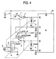
- Fig. 4 is a circuit diagram showing a circuit configuration of a main section of a power window apparatus according to a second embodiment of the present invention.
- This power window apparatus allows a window to be opened automatically if the apparatus is submerged in water.
- the second embodiment shown in Fig. 4 differs from the first embodiment shown in Fig. 1 only in that, in the window lowering switch formed of a one-circuit switch with two contacts, whereas the normally-closed, fixed contact is grounded in the first embodiment, the normally-closed, fixed contact is open in the second embodiment; and whereas the second reverse-current-blocking diode 8 is used in the first embodiment, the second reverse-current-blocking diode 8 is not used in the second embodiment.
- the second embodiment does not have any other differences in configuration from the first embodiment. Therefore, further descriptions of the configuration of the second embodiment will be omitted.
- the power window apparatus mounted inside a door is submerged in water, and, as described above, the window raising switch 1 and the window lowering switch 3 are also submerged in water.
- the window raising switch 1 water connects the normally-open, fixed contact to the movable contact as a resistor allowing continuity. Since the normally-closed, fixed contact is grounded, a current caused by the voltage of the car power source 11 flows into the ground through the water between the normally-open, fixed contact and the movable contact, and the contacts switched to the normally-closed, fixed contact side. The voltage is not applied to the window raising relay 2. Therefore, the contacts 2 1 of the window raising relay 2 are maintained at the connection condition shown in the figure.
- the window lowering switch 3 is the same as the window raising switch 1 in that water connects the normally-open, fixed contact to the movable contact as a resistor allowing continuity, in submergence. Since the normally-closed, fixed contact is in the open condition, the voltage of the car power source 11 is applied to the window lowering relay 4 through the water serving as a resistor allowing continuity between the normally-open, fixed contact and the movable contact to drive the window lowering relay 4. With the window lowering relay 4 being driven, its contacts 41 are switched from the connection condition shown in the figure to the other connection condition. The voltage of the car power source 11 is applied to the window opening and closing motor 9 to drive the motor 9 in the other direction. With this operation, since the window is lowered and automatically opened, the car driver and other passengers can escape from the opened window without operating the window lowering switch 3.
- a one-circuit switch with two contacts is used for the window lowering switch 4, its normally-closed, fixed contact is made open, and the normally-open, fixed contact is connected to the car power source 11.
- the power window apparatus may be configured such that a normally-open switch with one circuit and one contact is used for the window lowering switch 4 and its fixed contact is connected to the car power source 11.
- the window raising switch 1' shown in Fig. 2, may be used instead of the window raising switch 1.
- the window raising switch 1 is connected to the car-power-source side of the window raising relay 2, and the window lowering switch 3 is connected to the car-power-source side of the window lowering relay 4.
- the power window apparatus may be configured such that the window raising switch 1 is connected to the ground side of the window raising relay 2, and the window lowering switch 3 is connected to the ground side of the window lowering relay 4.
- the automatic raising switch 5, the automatic lowering switch 6, and the control integrated circuit 10 are used.
- the functions in each embodiment can be implemented.
- the window raising switch (the first switch) and the window lowering switch (the second switch) each have one circuit with two contacts, the fixed contacts which are switched when the first switch or the second switch is not operated are grounded or connected to the car power source, and the fixed contacts switched when the first switch and the second switch are operated are grounded, if a car drops into water, and water connects the contacts of the window raising switch (the first switch) and those of the window lowering switch (the second switch) as resistors allowing continuity due to submergence, a current caused by the voltage of the car power source flows into the ground through the water, and the voltage of the car power source does not drive the window raising relay (the first relay) or the window lowering relay (the second relay).
- the window lowering switch (the second switch)
- the contacts become short-circuited by the switching of the contacts, which were connected by water serving as a resistor allowing continuity.
- the voltage of the car power source drives the window lowering relay (the second relay) and the motor is rotated to open the window. Therefore, a passenger can escape from the car.
- the window raising switch (the first switch) has one circuit with two contacts, the fixed contact which is switched when the window raising switch (the first switch) is not operated is grounded, and the contacts of the window lowering switch (the second switch) are made open when the window lowering switch (the second switch) is not operated, if a car drops into water, and water connects the contacts of the window raising switch (the first switch) and those of the window lowering switch (the second switch) as resistors allowing continuity, due to submergence, a current caused by the voltage of the car power source flows into the ground through the water at the window raising switch (the first switch), and the voltage of the car power source does not drive the window raising relay (the first relay).
- the voltage of the car power source drives the window lowering relay (the second relay) through the water at the window lowering switch (the second switch) and the motor is rotated to automatically open the window. Therefore, a passenger can escape from the car without operating the window lowering switch (the second switch).
Landscapes
- Engineering & Computer Science (AREA)
- Mechanical Engineering (AREA)
- Power-Operated Mechanisms For Wings (AREA)
- Window Of Vehicle (AREA)
Description
- The present invention relates to power window apparatuses, and more specifically, to a power window apparatus which allows a door window to be opened by an operation of a window lowering switch if a car drops into water for some reason.
- If a car accidentally drops into water, electrical insulation between the contacts of a window raising switch and between those of a window lowering switch is unlikely to be maintained in a power window apparatus used for the car. Although each contact of the window raising switch and the window lowering switch is open, actually they are electrically connected. Therefore, even if the window lowering switch is operated, the lowering operation of the window, namely, an opening operation of the window cannot be performed.
- Fig. 5 is a circuit configuration of a main part of such a conventional power window apparatus.
- As shown in Fig. 5, the power window apparatus is formed of a
window raising switch 21, awindow raising relay 22 and itscontacts 221, awindow lowering switch 23, awindow lowering relay 24 and itscontacts 241, anautomatic raising switch 25, anautomatic lowering switch 26, a window opening andclosing motor 27, a control integrated circuit (IC) 28, and a car power source (battery) 29. - Between the
car power source 29 and the ground, thewindow raising switch 21 and thewindow raising relay 22 are connected in series, and thewindow lowering switch 23 and thewindow lowering relay 24 are also connected in series. A connection point "a" between thewindow raising switch 21 and thewindow raising relay 22 is connected to apin 1 ○ of the control integratedcircuit 28. A connection point "b" between thewindow lowering switch 23 and thewindow lowering relay 24 is connected to apin 2 ○ of the control integratedcircuit 28. Theautomatic raising switch 25 is connected between the connection point "a" and apin 3 ○ of the control integratedcircuit 28. Theautomatic lowering switch 26 is connected between the connection point "b" and thepin 3 ○ of the control integratedcircuit 28. Among thecontacts 221 of thewindow raising relay 22, a movable contact is connected to one end of the window opening and closingmotor 27, one fixed contact is connected to thecar power source 29, and the other fixed contact is connected to the ground. Among thecontacts 241 of thewindow lowering relay 24, a movable contact is connected to the other end of the window opening and closingmotor 27, one fixed contact is connected to thecar power source 29, and the other fixed contact is connected to the ground. Apin 4 ○ of the control integratedcircuit 28 is connected to thewindow raising relay 22, apin 5 ○ is connected to thewindow lowering relay 24, and apin 6 ○ is connected to thecar power source 29. - The power window apparatus configured as described above will roughly operate in the following way.
- When a driver of the car operates the
window raising switch 21, its contacts are closed and thecar power source 29 drives thewindow raising relay 22. Thecontacts 221 of thewindow raising relay 22 are switched on, the window opening and closingmotor 27 rotates in one direction, and thereby the window moves in the raising direction (closing direction). When the driver stops operating thewindow raising switch 21, the contacts become open and driving of thewindow raising relay 22 is stopped. Therefore, the window opening and closingmotor 27 also stops rotating and raising of the window stops. When the driver operates thewindow lowering switch 23, its contacts are closed and thepower source 29 drives thewindow lowering relay 24. Thecontacts 241 of thewindow lowering relay 24 are switched on, the window opening and closingmotor 27 rotates in the other direction, and thereby the window moves in the lowering direction (opening direction). When the driver stops operating thewindow lowering switch 23, the contacts become open and driving of thewindow lowering relay 24 is stopped. Therefore, the window opening and closingmotor 27 also stops rotating and lowering of the window stops. - When the driver operates the
automatic raising switch 25, its contacts are closed, thewindow raising switch 21 is operated at the same time, and its contacts also become closed. Since the contacts of thewindow raising switch 21 are closed, thecar power source 29 drives thewindow raising relay 22. In the same way as when thewindow raising switch 21 is operated as described above, the window opening and closingmotor 27 rotates in one direction, and thereby the window moves in the raising direction (closing direction). Since the contacts of thewindow raising switch 21 are closed and those of theautomatic raising switch 25 are closed, the voltage obtained at the connection point "a" is supplied to thepins 1 ○ and 3 ○ of the control integratedcircuit 28. In response to the supply of the voltage, the voltage of thecar power source 29 is latched and output from thepin 4 ○ of the control integratedcircuit 28, and sent to thewindow raising relay 22. Therefore, even if the operation of theautomatic raising switch 25 is stopped, its contacts become open, the operation of thewindow raising switch 21 is stopped at the same time, and its contacts become open. Since the voltage output from thepin 4 ○ has been latched, thewindow raising relay 22 continues being driven, the window opening and closingmotor 27 rotates in one direction, and thereby the window continues moving in the raising direction (closing direction). The window continues moving in the raising direction (closing direction) until the window is fully closed. - In the same way, when the driver operates the
automatic lowering switch 26, its contacts are closed, thewindow lowering switch 23 is operated at the same time, and its contacts also become closed. In the same way as when thewindow lowering switch 23 is operated as described above, the window opening and closingmotor 27 rotates in the other direction, and thereby the window moves in the lowering direction (opening direction). Since the contacts of thewindow lowering switch 23 are closed and those of theautomatic lowering switch 26 are closed, the voltage obtained at the connection point "b" is supplied to thepins 2 ○ and 3 ○ of the control integratedcircuit 28. In response to the supply of this voltage, the voltage of thecar power source 29 is latched and output from thepin 5 ○ of the control integratedcircuit 28, and sent to thewindow lowering relay 24. Therefore, even if the operation of theautomatic lowering switch 26 is stopped, its contacts become open, the operation of thewindow lowering switch 23 is stopped at the same time, and its contacts become open. Since the voltage output from thepin 5 ○ has been latched, thewindow lowering relay 24 continues being driven, the window opening and closingmotor 27 rotates in the other direction, and thereby the window continues moving in the lowering direction (opening direction). The window continues moving in the lowering direction (opening direction) until the window is fully opened. - If the car drops into water for some reason, and the
window raising switch 21 and thewindow lowering switch 23 in the conventional power window apparatus are submerged in water, water connects the contacts of each switch as resistors allowing continuity. Although each contact of thewindow raising switch 21 and thewindow lowering switch 23 is open, the output of thecar power source 29 is applied to thewindow raising relay 22 and thewindow lowering relay 24. Thewindow raising relay 22 and thewindow lowering relay 24 are driven at the same time, or they are half driven at the same time. As a result, theircontacts contacts window lowering switch 23 to open the window, the window opening and closingmotor 27 is not rotated. - As described above, if the car drops into water accidentally and the conventional power window apparatus is submerged in water, the apparatus cannot be operated normally any more.
- Conventional motor vehicle window control apparatus that incorporate one-touch activation are disclosed in US patent application numbers 4,575,662 and 4,683,975.
- Accordingly, it is an object of the present invention to provide a power window apparatus which allows a window to open with a switch operation even if the car drops into water accidentally and is submerged in water.
- Another object of the present invention is to provide a power window apparatus which allows a window to automatically open without a switch operation if the card drops into water and is submerged in water.
- According to an aspect of the present invention there is provided a power window apparatus comprising: a first series circuit with a first switch and a first relay, connected between a car power source and a ground; a second series circuit with a second switch and a second relay, connected between the car power source and the ground; and a motor connected to one of the contacts of the first relay at one side and to one of the contacts of the second relay in the other side, rotated in one direction due to switching of the contacts in the first relay when the first switch is operated to raise a window, and rotated in the other direction due to switching of the contacts in the second relay when the second switch is operated to lower the window, characterised in that the first switch and the second switch each have one circuit with two contacts, and the fixed contacts which are switched when the first switch or the second switch is not operated are grounded through minute gaps.
- One of the foregoing objects is also achieved according to another aspect of the present invention through the provision of a power window apparatus including: a first series circuit with a first switch and a first relay, connected between a car power source and a ground; a second series circuit with a second switch and a second relay, connected between the car power source and the ground; and a motor connected to one of the contacts of the first relay at one side and to one of the contacts of the second relay in the other side, rotated in one direction due to switching of the contacts in the first relay when the first switch is operated to raise a window, and rotated in the other direction due to switching of the contacts in the second relay when the second switch is operated to lower the window, characterised in that the first switch and the second switch each have one circuit with two contacts, and the fixed contacts which are switched when the first switch or the second switch is not operated are connected to the car power source.
- According to these aspects of the present invention, even if a car accidentally drops into water, a portion where the first switch and the second switch are disposed is submerged in water, and water connects the contacts of the first switch and also connects those of the second switch as resistors allowing continuity, since a current caused by the voltage of the car power source flows into the ground through the water serving as resistors allowing continuity and the movable contacts switched to the fixed contacts connected to the ground, the voltage of the car power source is not applied to the first relay or the second relay. Neither the first relay nor the second relay is operated due to connection by water serving as resistors allowing continuity. In such a condition, when the car driver operates the second switch, since the movable contacts are switched to the fixed contacts connected to the car power source or to the fixed contacts connected to the ground, and the contacts become short-circuited, which were connected by water serving as a resistor allowing continuity, the voltage of the car power source is applied to the second relay to drive it. The contacts thereof are switched, the motor is rotated in the other direction, and the window is opened.
- The other of the foregoing objects is achieved according to still another aspect of the present invention through the provision of a power window apparatus including: a first series circuit with a first switch and a first relay, connected between a car power source and a ground; a second series circuit with a second switch and a second relay, connected between the car power source and the ground; and a motor connected to one of the contacts of the first relay at one side and to one of the contacts of the second relay in the other side, rotated in one direction due to switching of the contacts in the first relay when the first switch is operated to raise a window, and rotated in the other direction due to switching of the contacts in the second relay when the second switch is operated to lower the window, wherein the first switch has one circuit with two contacts, the fixed contact which is switched when the first switch is not operated is grounded, and the second switch is open when not operated.
- According to this aspect of the present invention, if a car drops into water, a portion where the first switch and the second switch are disposed is submerged in water, and water connects the contacts of the first switch and those of the second switch as resistors allowing continuity, since a current caused by the voltage of the car power source flows into the ground through the water at the first switch and the movable contact switched to the fixed contact connected to the ground, the voltage of the car power source is not applied to the first relay and the first relay is not operated due to connection by water serving as a resistor allowing continuity. On the other hand, the voltage of the car power source is applied to the second relay through the water at the second switch to drive the second relay. The contacts of the second relay are switched, the motor is rotated in the other direction, and the window is automatically opened.
- Other objects and features of the present invention will become understood from the following description with reference to the accompanying drawings.
- Fig. 1 is a circuit diagram showing a circuit configuration of a main section of a power window apparatus according to a first embodiment of the present invention.
- Fig. 2 is a circuit diagram showing another configuration of a window raising switch and a window lowering switch.
- Fig. 3 is a circuit diagram showing a circuit configuration in a case in which the window raising switch is connected to the ground side of a window raising relay and the window lowering switch is connected to the ground side of the window lowering relay.
- Fig. 4 is a circuit diagram showing a circuit configuration of a main section of a power window apparatus according to a second embodiment of the present invention.
- Fig. 5 is a circuit diagram showing a circuit configuration of a main section of a conventional power window apparatus.
- Embodiments of the present invention will be described below by referring to the drawings.
- Fig. 1 is a circuit diagram showing a circuit configuration of a main part of a power window apparatus according to a first embodiment of the present invention.
- As shown in Fig. 1, the power window apparatus of the first embodiment is formed of a window raising switch (a first switch) 1, a window raising relay (a first relay) 2 and its
contacts 21, a window lowering switch (a second switch) 3, a window lowering relay (a second relay) 4 and itscontacts 41, anautomatic raising switch 5, anautomatic lowering switch 6, a first reverse-current-blockingdiode 7, a second reverse-current-blockingdiode 8, a window opening and closing motor 9, a control integrated circuit (IC) 10, and a car power source (battery) 11. - Between the
car power source 11 and the ground, a first series circuit formed of thewindow raising switch 1, the first reverse-current-blockingdiode 7, and thewindow raising relay 2, and a second series circuit formed of thewindow lowering switch 3, the second reverse-current-blockingdiode 8, and thewindow lowering relay 4 are connected. Thewindow raising switch 1 and thewindow lowering switch 2 each have one circuit with two contacts. Their normally closed, fixed contacts are grounded, their normally open, fixed contacts are connected to thecar power source 11, and their movable contacts are connected to the first reverse-current-blockingdiode 7 and the second reverse-current-blockingdiode 8. A connection point "a" between thewindow raising relay 2 and the first reverse-current-blockingdiode 7 is connected to aport 1 ○ of the control integratedcircuit 10. A connection point "b" between thewindow lowering relay 4 and the second reverse-current-blockingdiode 8 is connected to aport 2 ○ of the control integratedcircuit 10. One end of theautomatic raising switch 5 is connected to the connection point "a" and the other end is connected to aport 3 ○ of the control integratedcircuit 10. One end of the automatic loweringswitch 6 is connected to the connection point "b" and the other end is connected to aport 3 ○ of the control integratedcircuit 10. Among thecontacts 21 of thewindow raising relay 2, a movable contact is connected to one end of the window opening and closing motor 9, one fixed contact is connected to thecar power source 11, and the other fixed contact is connected to the ground. Among thecontacts 41 of thewindow lowering relay 4, a movable contact is connected to the other end of the window opening and closing motor 9, one fixed contact is connected to thecar power source 11, and the other fixed contact is connected to the ground. Aport 4 ○ of the control integratedcircuit 10 is connected to the connection point between thewindow raising relay 2 and the first reverse-current-blockingdiode 7, aport 5 ○ is connected to the connection point between thewindow lowering relay 4 and the second reverse-current-blockingdiode 8, and aport 6 ○ is connected to thecar power source 11. - The power window apparatus configured as described above according to the first embodiment will roughly operate in the following way.
- When a car driver operates the
window raising switch 1, its contacts are switched from the normally closed, fixed contact side (shown) to the normally open, fixed contact side. The voltage of thecar power source 11 is applied to thewindow raising relay 2 through thewindow raising switch 1 and the first reverse-current-blockingdiode 7 to drive thewindow raising relay 2. Then, thecontacts 21 of thewindow raising relay 2 are switched from the connection condition shown in the figure to the other connection condition. The voltage of thecar power source 11 is applied to the window opening and closing motor 9 to rotate the motor 9 in one direction. With the rotation of the window opening and closing motor 9 in one direction, the window is raised, namely, the window is moved in the closing direction. When the operation of thewindow raising switch 1 is stopped, its contacts are switched to the normally-closed, fixed contact side (shown). Since the voltage of thecar power source 11 is blocked by thewindow raising switch 1 and the driving of thewindow raising relay 2 is stopped, the window opening and closing motor 9 is stopped rotating. The raising of the window is stopped, and the window is held at that position. - When the driver operates the
window lowering switch 3, its contacts are switched from the normally closed, fixed contact side shown in the figure to the normally open, fixed contact side. The voltage of thecar power source 11 is applied to thewindow lowering relay 4 through thewindow lowering switch 3 and the second reverse-current-blockingdiode 8 to drive thewindow lowering relay 4. Then, thecontacts 41 of thewindow lowering relay 4 are switched from the connection condition shown in the figure to the other connection condition. The voltage of thecar power source 11 is applied to the window opening and closing motor 9 to rotate the motor in the other direction. With the rotation of the window opening and closing motor 9 in the other direction, the window is lowered, namely, the window is moved in the opening direction. When the operation of thewindow lowering switch 3 is stopped, its contacts are switched to the normally-closed, fixed contact side. Since the voltage of thecar power source 11 is blocked by thewindow lowering switch 3 and the driving of thewindow lowering relay 4 is stopped, the window opening and closing motor 9 is stopped rotating. The lowering of the window is stopped, and the window is held at that position. - When the driver operates the
automatic raising switch 5, thewindow raising switch 1 is also operated at the same time accordingly, the contacts of theautomatic raising switch 5 are closed, and the contacts of thewindow raising switch 1 are also switched from the normally-closed, fixed contact side shown in the figure to the normally-open, fixed contact side. When the contacts of thewindow raising switch 1 are switched to the normally-open, fixed contact side, the voltage of thecar power source 11 is applied to thewindow raising relay 2 through thewindow raising switch 1 and the first reverse-current-blockingdiode 7 to drive thewindow raising relay 2 in the same way as when thewindow raising switch 1 is operated, as described above. Then, the window opening and closing motor 9 is rotated in one direction. With the rotation of the window opening and closing motor 9 in one direction, the window is raised, namely, the window is moved in the closing direction. Since the contacts of thewindow raising switch 1 are switched to the normally-open, fixed contact side, and those of theautomatic raising switch 5 are closed, the voltage obtained at the connection point "a" is supplied to theports 1 ○ and 3 ○ of the control integratedcircuit 10. In response to the supply of this voltage, the control integratedcircuit 10 latches the voltage of thecar power source 11, applied to theport 6 ○, and outputs it from theport 4 ○ to apply to thewindow raising relay 2. If the operation of theautomatic raising switch 5 is stopped and the operation of thewindow raising switch 1 is stopped accordingly, the contacts of thewindow raising switch 1 are switched from the normally-open, fixed contact side to the normally-closed, fixed contact side, and the supply of the voltage of thecar power source 11 to thewindow raising relay 2 through thewindow raising switch 1 is stopped. Since the voltage of thecar power source 11 output from theport 4 ○ of the control integratedcircuit 10 has been latched, and the voltage is still being applied to thewindow raising relay 2, thewindow raising relay 2 continues being driven. Therefore, the window opening and closing motor 9 continues rotating in one direction, and thereby the window continues moving in the raising direction. The window continues moving in the raising direction until the window reaches the top so that it is fully closed. In this case, the first reverse-current-blockingdiode 7 is connected such that the voltage of thecar power source 11, output from theport 4 ○ of the control integratedcircuit 10, is all applied to thewindow raising relay 2. - In the same way as described above, when the driver operates the automatic lowering
switch 6, thewindow lowering switch 3 is also operated at the same time accordingly, the contacts of the automatic loweringswitch 6 are closed, and the contacts of thewindow lowering switch 3 are also switched from the normally-closed, fixed contact side shown in the figure to the normally-open, fixed contact side. When the contacts of thewindow lowering switch 3 are switched to the normally-open, fixed contact side, the voltage of thecar power source 11 is applied to thewindow lowering relay 4 through thewindow lowering switch 3 and the second reverse-current-blockingdiode 8 to drive thewindow lowering relay 4 in the same way as when thewindow lowering switch 3 is operated, as described above. Then, the window opening and closing motor 9 is rotated in the other direction. With the rotation of the window opening and closing motor 9 in this direction, the window is lowered, namely, the window is moved in the opening direction. Since the contacts of thewindow lowering switch 3 are switched to the normally-open, fixed contact side, and those of the automatic loweringswitch 6 are closed, the voltage obtained at the connection point "b" is supplied to theports 2 ○ and 3 ○ of the control integratedcircuit 10. In response to the supply of this voltage, the control integratedcircuit 10 latches the voltage of thecar power source 11, applied to theport 6 ○, and outputs it from theport 5 ○ to apply to thewindow lowering relay 4. If the operation of the automatic loweringswitch 6 is stopped and the operation of thewindow lowering switch 3 is stopped accordingly, the contacts of thewindow lowering switch 3 are switched from the normally-open, fixed contact side to the normally-closed, fixed contact side, and the supply of the voltage of thecar power source 11 to thewindow lowering relay 4 through thewindow lowering switch 3 is stopped. Since the voltage of thecar power source 11 output from theport 5 ○ of the control integratedcircuit 10 has been latched, and the voltage is still being applied to thewindow lowering relay 4, thewindow lowering relay 4 continues being driven. Therefore, the window opening and closing motor 9 continues rotating in the other direction, and thereby the window continues moving in the lowering direction. The window continues moving in the lowering direction until the window reaches the bottom so that it is fully opened. In this case, the second reverse-current-blockingdiode 8 is connected such that the voltage of thecar power source 11, output from theport 5 ○ of the control integratedcircuit 10, is all applied to thewindow lowering relay 4. - When the windows of the car are closed, if the car drops into water for some reason, the power window apparatus mounted inside a door is submerged in water, and the
window raising switch 1 and thewindow lowering switch 3 are also submerged in water. Although the power window apparatus is water-proof at its peripheral circuit, and thewindow raising switch 1 and thewindow lowering switch 3 are also water-proof, when the power window apparatus is submerged in water, the water comes into thewindow raising switch 1 and thewindow lowering switch 3 through small gaps. When thewindow raising switch 1 and thewindow lowering switch 3 are submerged in water, water connects their normally-open, fixed contacts and movable contacts as resistors allowing continuity. Since the normally-closed, fixed contacts of thewindow raising switch 1 and thewindow lowering switch 3 are grounded, a current caused by the voltage of thecar power source 11 flows into the ground through the water between the normally-open, fixed contact and the movable contact, and the contacts switched to the normally-closed, fixed contact side in each of thewindow raising switch 1 and thewindow lowering switch 3. Consequently, the voltage is not applied to thewindow raising relay 2 or thewindow lowering relay 4. Therefore, thecontacts window raising relay 2 and thewindow lowering relay 4 are in the connection conditions shown in the figure, and the window opening and closing motor 9 is not rotated. - In such a condition, when the driver operates the
window lowering switch 3, its contacts are switched from the normally-closed, fixed contact side to the normally-open, fixed contact side. The normally-open, fixed contact and the movable contact become short-circuited by the switching of the contacts, which were connected by water serving as a resistor allowing continuity. At the same time, the connection between the normally-closed, fixed contact and the movable contact is changed from the short-circuited condition to the open condition, and they are connected by water serving as a resistor allowing continuity. Therefore, the voltage of thecar power source 11 is applied to thewindow lowering relay 4 through thewindow lowering switch 3 which is in the short-circuited condition to drive thewindow lowering relay 4. With thewindow lowering relay 4 being driven, itscontacts 41 are switched from the connection condition shown in the figure to the other connection condition. The voltage of thecar power source 11 is applied to the window opening and closing motor 9 to drive the motor 9 in the other direction. With this operation, since the window is lowered and opened, the driver and other passengers can escape from the opened window. - As described above, even if the power window apparatus according to the first embodiment is submerged in water when the car accidentally drops into water, a window can be opened by operating the
window lowering switch 3. - In the power window apparatus according to the first embodiment, a one-circuit switch with two contacts in which the normally-closed, fixed contact is grounded is used for the
window raising switch 1 and thewindow lowering switch 3. Instead, a one-circuit switch with two contacts in which the normally-closed, fixed contact is not directly grounded but grounded through a minute gap may be used. - Fig. 2 shows a case in which such switches are used. Fig. 2 is a circuit diagram of a window raising switch and a window lowering switch.
- As shown in Fig. 2, a window raising switch 1' is the same as the
window raising switch 1 according to the first embodiment in terms of being a one-circuit switch with two contacts, but differs from thewindow raising switch 1 in that the normally-closed, fixed contact is grounded through a minute gap instead of being directly grounded. In the same way, a window lowering switch 3' is the same as thewindow lowering switch 3 according to the first embodiment in terms of being a one-circuit switch with two contacts, but differs from thewindow lowering switch 3 in that the normally-closed, fixed contact is grounded through a minute gap instead of being directly grounded. - With the use of the window raising switch 1' and the window lowering switch 3' having such a configuration, the power window apparatus is suited to a case in which water has a relatively-small resistance and the voltage of the
car power source 11 is much consumed if there is only the water serving as a resistor allowing continuity, between the normally-closed, fixed contact and the movable contact. - In the power window apparatus according to the first embodiment, the
window raising switch 1 and the first reverse-current-blockingdiode 7 are connected to the car-power-source (11) side of thewindow raising relay 2, and thewindow lowering switch 3 and the second reverse-current-blockingdiode 8 are connected to the car-power-source (11) side of thewindow lowering relay 4. The power window apparatus may be configured such that thewindow raising switch 1 and the first reverse-current-blockingdiode 7 are connected to the ground side of thewindow raising relay 2, and thewindow lowering switch 3 and the second reverse-current-blockingdiode 8 are connected to the ground side of thewindow lowering relay 4. - Fig. 3 is a circuit diagram of a power window apparatus in which a
window raising switch 1 is connected to the ground side of awindow raising relay 2 and awindow lowering switch 3 is connected to the ground side of awindow lowering relay 4, with only the portion directly related to thewindow raising relay 2 and thewindow lowering relay 4 being illustrated. - In Fig. 3, the same symbols are assigned to the same components as those used in Fig. 1.
- As shown in Fig. 3, the normally-closed, fixed contact of the
window raising switch 1 is connected to acar power source 11, the normally-open, fixed contact is grounded, and the movable contact is connected to the other end (ground-side terminal) of thewindow raising relay 2 through a first reverse-current-blockingdiode 7. One end (power-side terminal) of thewindow raising relay 2 is directly connected to thecar power source 11. The normally-closed, fixed contact of thewindow lowering switch 3 is connected to thecar power source 11, the normally-open, fixed contact is grounded, and the movable contact is connected to the other end (ground-side terminal) of thewindow lowering relay 4 through a second reverse-current-blockingdiode 8. One end (power-side terminal) of thewindow lowering relay 4 is directly connected to thecar power source 11. - Since the operation of the power window apparatus having the above configuration is substantially the same as that of the power window apparatus according to the first embodiment, a detailed description thereof will be omitted.
- Also in the power window apparatus having the above configuration, the window raising switch 1' and the window lowering switch 3', shown in Fig. 2, may be used.
- In each of the above cases, if the car accidentally drops into water and the power window apparatus is submerged in water, a window can be opened by operating the
window lowering switch 3. It is preferred that a window be automatically opened without operating thewindow lowering switch 3 if the power window apparatus is submerged in water. - Fig. 4 is a circuit diagram showing a circuit configuration of a main section of a power window apparatus according to a second embodiment of the present invention. This power window apparatus allows a window to be opened automatically if the apparatus is submerged in water.
- In Fig. 4, the same symbols are assigned to the same components as those shown in Fig. 1.
- The second embodiment shown in Fig. 4 differs from the first embodiment shown in Fig. 1 only in that, in the window lowering switch formed of a one-circuit switch with two contacts, whereas the normally-closed, fixed contact is grounded in the first embodiment, the normally-closed, fixed contact is open in the second embodiment; and whereas the second reverse-current-blocking
diode 8 is used in the first embodiment, the second reverse-current-blockingdiode 8 is not used in the second embodiment. The second embodiment does not have any other differences in configuration from the first embodiment. Therefore, further descriptions of the configuration of the second embodiment will be omitted. - As for operations in the second embodiment, since normal operations, that is, an operation performed when the
window raising switch 1 is operated, an operation performed when thewindow lowering switch 3 is operated, an operation performed when theautomatic raising switch 5 is operated, and an operation performed when the automatic loweringswitch 6 is operated, are substantially the same as the corresponding operations in the first embodiment, that is, the operation performed when thewindow raising switch 1 is operated, an operation performed when thewindow lowering switch 3 is operated, an operation performed when theautomatic raising switch 5 is operated, and an operation performed when the automatic loweringswitch 6 is operated, descriptions of these operations will be omitted. An operation of the power window apparatus performed if the apparatus is submerged in water will be described below. - When the windows of a car are closed, if the car drops into water for some reason, the power window apparatus mounted inside a door is submerged in water, and, as described above, the
window raising switch 1 and thewindow lowering switch 3 are also submerged in water. In thewindow raising switch 1, water connects the normally-open, fixed contact to the movable contact as a resistor allowing continuity. Since the normally-closed, fixed contact is grounded, a current caused by the voltage of thecar power source 11 flows into the ground through the water between the normally-open, fixed contact and the movable contact, and the contacts switched to the normally-closed, fixed contact side. The voltage is not applied to thewindow raising relay 2. Therefore, thecontacts 21 of thewindow raising relay 2 are maintained at the connection condition shown in the figure. Thewindow lowering switch 3 is the same as thewindow raising switch 1 in that water connects the normally-open, fixed contact to the movable contact as a resistor allowing continuity, in submergence. Since the normally-closed, fixed contact is in the open condition, the voltage of thecar power source 11 is applied to thewindow lowering relay 4 through the water serving as a resistor allowing continuity between the normally-open, fixed contact and the movable contact to drive thewindow lowering relay 4. With thewindow lowering relay 4 being driven, itscontacts 41 are switched from the connection condition shown in the figure to the other connection condition. The voltage of thecar power source 11 is applied to the window opening and closing motor 9 to drive the motor 9 in the other direction. With this operation, since the window is lowered and automatically opened, the car driver and other passengers can escape from the opened window without operating thewindow lowering switch 3. - As described above, if the car drops into water accidentally and the power window apparatus according to the second embodiment is submerged in water, a window is automatically opened without operating the
window lowering switch 3. - In the second embodiment, a one-circuit switch with two contacts is used for the
window lowering switch 4, its normally-closed, fixed contact is made open, and the normally-open, fixed contact is connected to thecar power source 11. The power window apparatus may be configured such that a normally-open switch with one circuit and one contact is used for thewindow lowering switch 4 and its fixed contact is connected to thecar power source 11. - Also in this second embodiment, the window raising switch 1', shown in Fig. 2, may be used instead of the
window raising switch 1. - In the power window apparatus according to the second embodiment, the
window raising switch 1 is connected to the car-power-source side of thewindow raising relay 2, and thewindow lowering switch 3 is connected to the car-power-source side of thewindow lowering relay 4. The power window apparatus may be configured such that thewindow raising switch 1 is connected to the ground side of thewindow raising relay 2, and thewindow lowering switch 3 is connected to the ground side of thewindow lowering relay 4. - In each of the above embodiments, the
automatic raising switch 5, the automatic loweringswitch 6, and the control integratedcircuit 10 are used. As a simplified power window apparatus, if theautomatic raising switch 5, the automatic loweringswitch 6, and the circuits related thereto, and the control integratedcircuit 10 are omitted, the functions in each embodiment can be implemented. - As described above, since the window raising switch (the first switch) and the window lowering switch (the second switch) each have one circuit with two contacts, the fixed contacts which are switched when the first switch or the second switch is not operated are grounded or connected to the car power source, and the fixed contacts switched when the first switch and the second switch are operated are grounded, if a car drops into water, and water connects the contacts of the window raising switch (the first switch) and those of the window lowering switch (the second switch) as resistors allowing continuity due to submergence, a current caused by the voltage of the car power source flows into the ground through the water, and the voltage of the car power source does not drive the window raising relay (the first relay) or the window lowering relay (the second relay). In such a condition, when the window lowering switch (the second switch) is operated, the contacts become short-circuited by the switching of the contacts, which were connected by water serving as a resistor allowing continuity. The voltage of the car power source drives the window lowering relay (the second relay) and the motor is rotated to open the window. Therefore, a passenger can escape from the car.
- Since the window raising switch (the first switch) has one circuit with two contacts, the fixed contact which is switched when the window raising switch (the first switch) is not operated is grounded, and the contacts of the window lowering switch (the second switch) are made open when the window lowering switch (the second switch) is not operated, if a car drops into water, and water connects the contacts of the window raising switch (the first switch) and those of the window lowering switch (the second switch) as resistors allowing continuity, due to submergence, a current caused by the voltage of the car power source flows into the ground through the water at the window raising switch (the first switch), and the voltage of the car power source does not drive the window raising relay (the first relay). On the other hand, the voltage of the car power source drives the window lowering relay (the second relay) through the water at the window lowering switch (the second switch) and the motor is rotated to automatically open the window. Therefore, a passenger can escape from the car without operating the window lowering switch (the second switch).
- While the presently preferred embodiments of the present invention have been shown and described, it is to be understood that these disclosures are for the purpose of illustration and that various changes and modifications may be made without departing from the scope of the invention as set forth in the appended claims.
Claims (4)
- A power window apparatus comprising:characterised in that the first switch and the second switch each have one circuit with two contacts, and the fixed contacts which are switched when the first switch or the second switch is not operated are grounded through minute gaps.a first series circuit with a first switch (1') and a first relay (2), connected between a car power source (11) and a ground;a second series circuit with a second switch (3') and a second relay (4), connected between the car power source (11) and the ground; anda motor (9) connected to one of the contacts (21) of the first relay at one side and to one of the contacts (41) of the second relay in the other side, rotated in one direction due to switching of the contacts in the first relay when the first switch is operated to raise a window, and rotated in the other direction due to switching of the contacts in the second relay when the second switch is operated to lower the window,
- A power window apparatus comprising:characterised in that the first switch has one circuit with two contacts, the fixed contact which is switched when the first switch is not operated is grounded, and the second switch is open when not operated.a first series circuit with a first switch (1) and a first relay (2), connected between a car power source (11) and a ground;a second series circuit with a second switch (3) and a second relay (4), connected between the car power source (11) and the ground; anda motor (9) connected to one of the contacts (21) of the first relay at one side and to one of the contacts (41) of the second relay in the other side, rotated in one direction due to switching of the contacts in the first relay when the first switch is operated to raise a window, and rotated in the other direction due to switching of the contacts in the second relay when the second switch is operated to lower the window,
- A power window apparatus according to Claim 2, wherein the fixed contact which is switched when the first switch is not operated is grounded through a minute gap.
- A power window apparatus comprising:characterised in that the first switch and the second switch each have one circuit with two contacts, and the fixed contacts which are switched when the first switch or the second switch is not operated are connected to the car power source.a first series circuit with a first switch (1) and a first relay (2), connected between a car power source (11) and a ground;a second series circuit with a second switch (3) and a second relay (4), connected between the car power source (11) and the ground; anda motor (9) connected to one of the contacts (21) of the first relay at one side and to one of the contacts (41) of the second relay in the other side, rotated in one direction due to switching of the contacts in the first relay when the first switch is operated to raise a window, and rotated in the other direction due to switching of the contacts in the second relay when the second switch is operated to lower the window,
Applications Claiming Priority (3)
| Application Number | Priority Date | Filing Date | Title |
|---|---|---|---|
| JP17592697A JP3461432B2 (en) | 1997-07-01 | 1997-07-01 | Power window device |
| JP17592697 | 1997-07-01 | ||
| JP175926/97 | 1997-07-01 |
Publications (3)
| Publication Number | Publication Date |
|---|---|
| EP0889192A2 EP0889192A2 (en) | 1999-01-07 |
| EP0889192A3 EP0889192A3 (en) | 1999-05-06 |
| EP0889192B1 true EP0889192B1 (en) | 2003-03-19 |
Family
ID=16004673
Family Applications (1)
| Application Number | Title | Priority Date | Filing Date |
|---|---|---|---|
| EP98305047A Expired - Lifetime EP0889192B1 (en) | 1997-07-01 | 1998-06-26 | Power window apparatus |
Country Status (4)
| Country | Link |
|---|---|
| US (1) | US6031296A (en) |
| EP (1) | EP0889192B1 (en) |
| JP (1) | JP3461432B2 (en) |
| DE (1) | DE69812235T2 (en) |
Families Citing this family (18)
| Publication number | Priority date | Publication date | Assignee | Title |
|---|---|---|---|---|
| JP3269991B2 (en) * | 1997-07-22 | 2002-04-02 | 本田技研工業株式会社 | Power window drive circuit |
| JP2000154682A (en) * | 1998-11-20 | 2000-06-06 | Fuji Heavy Ind Ltd | Power window equipment |
| JP3730807B2 (en) * | 1999-05-21 | 2006-01-05 | アルプス電気株式会社 | Submergence detection power window device |
| JP2001018737A (en) * | 1999-07-09 | 2001-01-23 | Yazaki Corp | Vehicle submergence countermeasure device |
| AU757313B2 (en) | 1999-08-02 | 2003-02-13 | Kabushiki Kaisha Tokai-Rika-Denki-Seisakusho | Power window switch circuit |
| JP4510182B2 (en) * | 1999-08-02 | 2010-07-21 | 株式会社東海理化電機製作所 | Power window switch circuit |
| DE50011524D1 (en) * | 2000-01-08 | 2005-12-08 | Kostal Leopold Gmbh & Co Kg | ELECTRICAL CIRCUIT ARRANGEMENT FOR CONTROLLING AN ELECTRIC MOTOR IN A MOTOR VEHICLE |
| JP3759368B2 (en) | 2000-03-14 | 2006-03-22 | アルプス電気株式会社 | Submergence detection power window device |
| US6249732B1 (en) * | 2000-06-16 | 2001-06-19 | Meritor Light Vehicle Technology, Llc | Window characteristic mapping for object detection |
| JP3684328B2 (en) * | 2000-08-25 | 2005-08-17 | アルプス電気株式会社 | Power window equipment |
| JP3896292B2 (en) * | 2002-02-14 | 2007-03-22 | アルプス電気株式会社 | Submersible opening / closing body drive circuit |
| US6756754B2 (en) | 2002-10-01 | 2004-06-29 | Siemens Vdo Automotive Inc. | Integrated one touch up and down windowlift motor with direct sense for anti-pinch |
| JP4085375B2 (en) * | 2003-02-12 | 2008-05-14 | オムロン株式会社 | Opening and closing body control device |
| JP4047757B2 (en) * | 2003-04-25 | 2008-02-13 | 株式会社東海理化電機製作所 | Power window device |
| JP2004339708A (en) * | 2003-05-13 | 2004-12-02 | Tokai Rika Co Ltd | Power window device |
| DE102004007328A1 (en) | 2004-02-14 | 2005-09-01 | Leopold Kostal Gmbh & Co Kg | Electrical circuit arrangement |
| CN104790802B (en) * | 2015-04-23 | 2017-01-04 | 重庆大学 | The control method of automobile automatic window-closing system |
| DE102018211111A1 (en) * | 2018-07-05 | 2020-01-09 | Faurecia Innenraum Systeme Gmbh | Safety control device, vehicle interior trim part comprising a corresponding safety control device and method for controlling a closing process and / or opening process of a vehicle window |
Family Cites Families (14)
| Publication number | Priority date | Publication date | Assignee | Title |
|---|---|---|---|---|
| FR2460383A1 (en) * | 1979-06-28 | 1981-01-23 | Peugeot Aciers Et Outillage | DEVICE FOR ELECTRICALLY CONTROLLING WINDOWS, ESPECIALLY OF A MOTOR VEHICLE |
| US4575662A (en) * | 1984-11-26 | 1986-03-11 | General Motors Corporation | Vehicle power window control circuit |
| US4562387A (en) * | 1984-11-26 | 1985-12-31 | General Motors Corporation | Vehicle power window control |
| US4678975A (en) * | 1986-01-06 | 1987-07-07 | Ford Motor Company | Motor control circuit for motor driven power windows |
| US4683975A (en) * | 1986-09-30 | 1987-08-04 | General Motors Corporation | Vehicle power window control |
| US5138182A (en) * | 1988-07-28 | 1992-08-11 | Kabushiki Kaisha Tokai-Rika-Denki-Seisakusho | Apparatus for controlling power window regulator |
| JP2674838B2 (en) * | 1989-08-23 | 1997-11-12 | アスモ株式会社 | Wind glass lifting device and window drive motor |
| JPH07230736A (en) * | 1994-02-18 | 1995-08-29 | Shigetoshi Matsuzuka | Pressure conductive automatic switch |
| JPH08203399A (en) * | 1994-02-28 | 1996-08-09 | Shigetoshi Matsuzuka | Pressure difference switch |
| US5572098A (en) * | 1994-07-01 | 1996-11-05 | General Motors Corporation | Motor vehicle accessory control with control module having single power terminal |
| DE29617425U1 (en) * | 1996-10-08 | 1996-11-28 | Postler, Karl, Dipl.-Ing., 46562 Voerde | Installation of an automatic control of electrical locking devices on vehicles to "open" with a given time delay and negative acceleration after an accident |
| US5731675A (en) * | 1996-12-10 | 1998-03-24 | Trw Inc. | Adjustable motor control circuit for power windows |
| JP3043616U (en) | 1997-03-03 | 1997-11-28 | 金造 金子 | Window glass Electric circuit for automatically opening windows when submerged in an electric vehicle |
| US5867357A (en) * | 1997-06-19 | 1999-02-02 | Eaton Corporation | Dynamic protection circuit for a motor type load |
-
1997
- 1997-07-01 JP JP17592697A patent/JP3461432B2/en not_active Expired - Lifetime
-
1998
- 1998-06-26 DE DE69812235T patent/DE69812235T2/en not_active Expired - Lifetime
- 1998-06-26 EP EP98305047A patent/EP0889192B1/en not_active Expired - Lifetime
- 1998-07-01 US US09/108,685 patent/US6031296A/en not_active Expired - Lifetime
Also Published As
| Publication number | Publication date |
|---|---|
| DE69812235D1 (en) | 2003-04-24 |
| EP0889192A2 (en) | 1999-01-07 |
| US6031296A (en) | 2000-02-29 |
| DE69812235T2 (en) | 2003-08-21 |
| EP0889192A3 (en) | 1999-05-06 |
| JP3461432B2 (en) | 2003-10-27 |
| JPH1122300A (en) | 1999-01-26 |
Similar Documents
| Publication | Publication Date | Title |
|---|---|---|
| EP0889192B1 (en) | Power window apparatus | |
| EP0931899B1 (en) | Power window device and a control device used for the same | |
| EP1134631B1 (en) | Submergence-detecting power-window apparatus | |
| US8134312B2 (en) | Motor control circuit and power window device | |
| US6081085A (en) | Power window apparatus | |
| KR100300370B1 (en) | Power window apparatus for a vehicle | |
| EP0921256B1 (en) | Waterproof power window device | |
| JP3756718B2 (en) | Water resistant power window device | |
| US6246564B1 (en) | Activating device | |
| JPH048587B2 (en) | ||
| KR100943998B1 (en) | Power window devices | |
| US6002224A (en) | One touch vehicle window operating circuit | |
| JP4399056B2 (en) | Window opening and closing device | |
| JPS58164876A (en) | Safety apparatus in slide type automatic door | |
| JP3480233B2 (en) | Control circuit for vehicle switchgear | |
| JP2001271555A (en) | Power window device | |
| JP3461437B2 (en) | Waterproof power window device | |
| JP3602955B2 (en) | Waterproof power window device | |
| KR950005606Y1 (en) | Power window of car | |
| JP3461438B2 (en) | Waterproof power window device | |
| JPH061026B2 (en) | Vehicle equipment drive | |
| JPH11208265A5 (en) | ||
| JPH0235828B2 (en) | ||
| KR20010076483A (en) | Method and device of power window for vehicle | |
| KR200142167Y1 (en) | Apparatus for controlling operating velocity of power window for a car |
Legal Events
| Date | Code | Title | Description |
|---|---|---|---|
| PUAI | Public reference made under article 153(3) epc to a published international application that has entered the european phase |
Free format text: ORIGINAL CODE: 0009012 |
|
| AK | Designated contracting states |
Kind code of ref document: A2 Designated state(s): DE FR GB NL |
|
| AX | Request for extension of the european patent |
Free format text: AL;LT;LV;MK;RO;SI |
|
| PUAL | Search report despatched |
Free format text: ORIGINAL CODE: 0009013 |
|
| AK | Designated contracting states |
Kind code of ref document: A3 Designated state(s): AT BE CH CY DE DK ES FI FR GB GR IE IT LI LU MC NL PT SE |
|
| AX | Request for extension of the european patent |
Free format text: AL;LT;LV;MK;RO;SI |
|
| 17P | Request for examination filed |
Effective date: 19991103 |
|
| AKX | Designation fees paid |
Free format text: DE FR GB NL |
|
| 17Q | First examination report despatched |
Effective date: 20010608 |
|
| GRAG | Despatch of communication of intention to grant |
Free format text: ORIGINAL CODE: EPIDOS AGRA |
|
| GRAG | Despatch of communication of intention to grant |
Free format text: ORIGINAL CODE: EPIDOS AGRA |
|
| GRAH | Despatch of communication of intention to grant a patent |
Free format text: ORIGINAL CODE: EPIDOS IGRA |
|
| GRAH | Despatch of communication of intention to grant a patent |
Free format text: ORIGINAL CODE: EPIDOS IGRA |
|
| GRAA | (expected) grant |
Free format text: ORIGINAL CODE: 0009210 |
|
| RIN1 | Information on inventor provided before grant (corrected) |
Inventor name: SASAKI, AKIRAROIYARUSHATO-ICHINAKAKOEN RM 307, Inventor name: TAKAGI, ISAO |
|
| AK | Designated contracting states |
Designated state(s): DE FR GB NL |
|
| REG | Reference to a national code |
Ref country code: GB Ref legal event code: FG4D |
|
| REF | Corresponds to: |
Ref document number: 69812235 Country of ref document: DE Date of ref document: 20030424 Kind code of ref document: P |
|
| ET | Fr: translation filed | ||
| PLBE | No opposition filed within time limit |
Free format text: ORIGINAL CODE: 0009261 |
|
| STAA | Information on the status of an ep patent application or granted ep patent |
Free format text: STATUS: NO OPPOSITION FILED WITHIN TIME LIMIT |
|
| 26N | No opposition filed |
Effective date: 20031222 |
|
| PGFP | Annual fee paid to national office [announced via postgrant information from national office to epo] |
Ref country code: GB Payment date: 20050512 Year of fee payment: 8 |
|
| PGFP | Annual fee paid to national office [announced via postgrant information from national office to epo] |
Ref country code: NL Payment date: 20050616 Year of fee payment: 8 |
|
| PGFP | Annual fee paid to national office [announced via postgrant information from national office to epo] |
Ref country code: FR Payment date: 20050617 Year of fee payment: 8 |
|
| PG25 | Lapsed in a contracting state [announced via postgrant information from national office to epo] |
Ref country code: GB Free format text: LAPSE BECAUSE OF NON-PAYMENT OF DUE FEES Effective date: 20060626 |
|
| PG25 | Lapsed in a contracting state [announced via postgrant information from national office to epo] |
Ref country code: NL Free format text: LAPSE BECAUSE OF NON-PAYMENT OF DUE FEES Effective date: 20070101 |
|
| GBPC | Gb: european patent ceased through non-payment of renewal fee |
Effective date: 20060626 |
|
| NLV4 | Nl: lapsed or anulled due to non-payment of the annual fee |
Effective date: 20070101 |
|
| REG | Reference to a national code |
Ref country code: FR Ref legal event code: ST Effective date: 20070228 |
|
| PG25 | Lapsed in a contracting state [announced via postgrant information from national office to epo] |
Ref country code: FR Free format text: LAPSE BECAUSE OF NON-PAYMENT OF DUE FEES Effective date: 20060630 |
|
| REG | Reference to a national code |
Ref country code: DE Ref legal event code: R082 Ref document number: 69812235 Country of ref document: DE Representative=s name: DREISS PATENTANWAELTE PARTG MBB, DE Ref country code: DE Ref legal event code: R081 Ref document number: 69812235 Country of ref document: DE Owner name: SUBARU CORPORATION, JP Free format text: FORMER OWNERS: ALPS ELECTRIC CO., LTD., TOKIO/TOKYO, JP; FUJI HEAVY INDUSTRIES LTD., TOKYO, JP Ref country code: DE Ref legal event code: R081 Ref document number: 69812235 Country of ref document: DE Owner name: ALPS ELECTRIC CO., LTD., JP Free format text: FORMER OWNERS: ALPS ELECTRIC CO., LTD., TOKIO/TOKYO, JP; FUJI HEAVY INDUSTRIES LTD., TOKYO, JP |
|
| PGFP | Annual fee paid to national office [announced via postgrant information from national office to epo] |
Ref country code: DE Payment date: 20170621 Year of fee payment: 20 |
|
| REG | Reference to a national code |
Ref country code: DE Ref legal event code: R071 Ref document number: 69812235 Country of ref document: DE |