EP0876856A2 - High performance wire rolling mill - Google Patents
High performance wire rolling mill Download PDFInfo
- Publication number
- EP0876856A2 EP0876856A2 EP98108138A EP98108138A EP0876856A2 EP 0876856 A2 EP0876856 A2 EP 0876856A2 EP 98108138 A EP98108138 A EP 98108138A EP 98108138 A EP98108138 A EP 98108138A EP 0876856 A2 EP0876856 A2 EP 0876856A2
- Authority
- EP
- European Patent Office
- Prior art keywords
- rolling mill
- wire
- einer
- winding
- mill according
- Prior art date
- Legal status (The legal status is an assumption and is not a legal conclusion. Google has not performed a legal analysis and makes no representation as to the accuracy of the status listed.)
- Granted
Links
Images

Classifications
-
- B—PERFORMING OPERATIONS; TRANSPORTING
- B21—MECHANICAL METAL-WORKING WITHOUT ESSENTIALLY REMOVING MATERIAL; PUNCHING METAL
- B21B—ROLLING OF METAL
- B21B1/00—Metal-rolling methods or mills for making semi-finished products of solid or profiled cross-section; Sequence of operations in milling trains; Layout of rolling-mill plant, e.g. grouping of stands; Succession of passes or of sectional pass alternations
- B21B1/16—Metal-rolling methods or mills for making semi-finished products of solid or profiled cross-section; Sequence of operations in milling trains; Layout of rolling-mill plant, e.g. grouping of stands; Succession of passes or of sectional pass alternations for rolling wire rods, bars, merchant bars, rounds wire or material of like small cross-section
- B21B1/18—Metal-rolling methods or mills for making semi-finished products of solid or profiled cross-section; Sequence of operations in milling trains; Layout of rolling-mill plant, e.g. grouping of stands; Succession of passes or of sectional pass alternations for rolling wire rods, bars, merchant bars, rounds wire or material of like small cross-section in a continuous process
-
- B—PERFORMING OPERATIONS; TRANSPORTING
- B21—MECHANICAL METAL-WORKING WITHOUT ESSENTIALLY REMOVING MATERIAL; PUNCHING METAL
- B21B—ROLLING OF METAL
- B21B1/00—Metal-rolling methods or mills for making semi-finished products of solid or profiled cross-section; Sequence of operations in milling trains; Layout of rolling-mill plant, e.g. grouping of stands; Succession of passes or of sectional pass alternations
- B21B1/46—Metal-rolling methods or mills for making semi-finished products of solid or profiled cross-section; Sequence of operations in milling trains; Layout of rolling-mill plant, e.g. grouping of stands; Succession of passes or of sectional pass alternations for rolling metal immediately subsequent to continuous casting
- B21B1/466—Metal-rolling methods or mills for making semi-finished products of solid or profiled cross-section; Sequence of operations in milling trains; Layout of rolling-mill plant, e.g. grouping of stands; Succession of passes or of sectional pass alternations for rolling metal immediately subsequent to continuous casting in a non-continuous process, i.e. the cast being cut before rolling
-
- B—PERFORMING OPERATIONS; TRANSPORTING
- B21—MECHANICAL METAL-WORKING WITHOUT ESSENTIALLY REMOVING MATERIAL; PUNCHING METAL
- B21B—ROLLING OF METAL
- B21B15/00—Arrangements for performing additional metal-working operations specially combined with or arranged in, or specially adapted for use in connection with, metal-rolling mills
- B21B2015/0057—Coiling the rolled product
-
- B—PERFORMING OPERATIONS; TRANSPORTING
- B21—MECHANICAL METAL-WORKING WITHOUT ESSENTIALLY REMOVING MATERIAL; PUNCHING METAL
- B21B—ROLLING OF METAL
- B21B2203/00—Auxiliary arrangements, devices or methods in combination with rolling mills or rolling methods
- B21B2203/18—Rolls or rollers
- B21B2203/185—Reversible rolls for changing grooves
-
- B—PERFORMING OPERATIONS; TRANSPORTING
- B21—MECHANICAL METAL-WORKING WITHOUT ESSENTIALLY REMOVING MATERIAL; PUNCHING METAL
- B21B—ROLLING OF METAL
- B21B45/00—Devices for surface or other treatment of work, specially combined with or arranged in, or specially adapted for use in connection with, metal-rolling mills
- B21B45/02—Devices for surface or other treatment of work, specially combined with or arranged in, or specially adapted for use in connection with, metal-rolling mills for lubricating, cooling, or cleaning
- B21B45/0203—Cooling
- B21B45/0209—Cooling devices, e.g. using gaseous coolants
- B21B45/0215—Cooling devices, e.g. using gaseous coolants using liquid coolants, e.g. for sections, for tubes
- B21B45/0224—Cooling devices, e.g. using gaseous coolants using liquid coolants, e.g. for sections, for tubes for wire, rods, rounds, bars
-
- Y—GENERAL TAGGING OF NEW TECHNOLOGICAL DEVELOPMENTS; GENERAL TAGGING OF CROSS-SECTIONAL TECHNOLOGIES SPANNING OVER SEVERAL SECTIONS OF THE IPC; TECHNICAL SUBJECTS COVERED BY FORMER USPC CROSS-REFERENCE ART COLLECTIONS [XRACs] AND DIGESTS
- Y10—TECHNICAL SUBJECTS COVERED BY FORMER USPC
- Y10T—TECHNICAL SUBJECTS COVERED BY FORMER US CLASSIFICATION
- Y10T29/00—Metal working
- Y10T29/51—Plural diverse manufacturing apparatus including means for metal shaping or assembling
- Y10T29/5184—Casting and working
Definitions
- High-performance wire rod mills with the generic features in the aforementioned preamble of claim 1 are in the prior art known. This includes individual components of the system concept described, but these are not yet sufficient to in terms of the desired layout for minimized space requirements and investment costs to implement a convincing new concept.
- the invention described therein lies the Task based on a method for heat treating steel wire from the rolling heat, the steel after exiting the last Scaffold intermittently quenched and through Temperature compensation with a core cross section is heated again and in the pearlite transformation region with a medium temperature from 600 to 650 ° C occurs in such a way that the previous usual lengths, considerable at increased rolling speeds which can significantly reduce cooling distances.
- This will be after this Document reached by quenching the wire surface intermittently up to 70 ° C above the martensite transformation temperature, at least to 400 ° C, is cooled, and that the wire of intermittent cooling for a time from 0.6 to 0.7 seconds is exposed. This is done in a manner known per se Way, water cooling quenching and temperature compensation under air cooling.
- the invention lies The task is based on known individual components of the aforementioned system concepts to be combined with new device elements in such a way that the considerable hitherto usual at increased rolling speeds Lengths of the cooling section can be significantly reduced, so that in their functional interaction the concept of a particularly space-saving design of the system can be realized can.
- design in conjunction with the direct use of a CC-casting plant or a CC-casting wheel for high production is an extremely compact overall system by increasing the coil weights of, for example, 2 t 5 t possible.
- An embodiment of the system provides that the winding coil arrangement for wire from 6 to 16 mm and for round steel from 18 to 40 mm is designed.
- the winding spools can advantageously in a winding station be arranged and they can be inside the take-up station Means for moving the winding spools between the finished lines have.
- Another also advantageous embodiment provides that the Water cooling section Means for moving them to the finished lines owns.
- the means for moving can be a great advantage the winding coils and the means for moving the water cooling section be synchronously coupled with each other.
- CC is an abbreviation for continuous Casting.
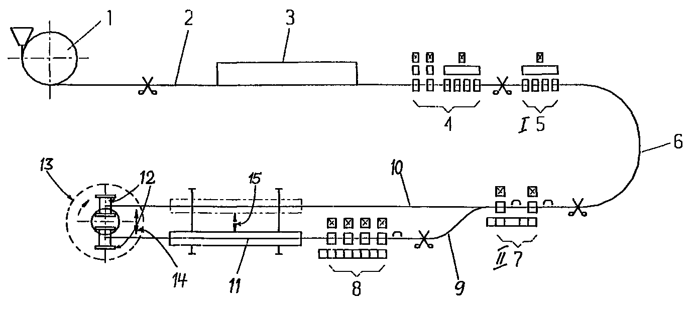
- a buffer furnace 3 to compensate for Production differences between the CC system 1 and rolling mill as well provided to compensate for smaller mill malfunctions.
- a compact pre-4 and Intermediate road I 5 which are designed such that a roll change is only required in the weekly repair shift, where, for example, the stands with two-caliber rollers for mutual Caliber insert are equipped.
- the scaffolds have through short bale length, high rigidity.
- an intermediate road II 7 to Generation of thick finished dimensions or pre-sections (e.g. 18-40 mm diameter) for the finishing train, designed for the fastest Scaffolding change.
- the intermediate road II 7 branches off the Finishing line 10 from a parallel finishing line 9 in which the finishing train 8 (for example for 6-16 mm rolling stock diameter) is arranged.
- the water cooling section is located on the following outlet section 11 with means 15 for displacement between the finished lines 9 and 10 is equipped. This is subordinate to the Slidable winding spool assembly 12, which also means 14 within the winding station 13 for moving between the Finished lines 9 and 10 is equipped.
Landscapes
- Engineering & Computer Science (AREA)
- Mechanical Engineering (AREA)
- Metal Rolling (AREA)
- Heat Treatment Of Steel (AREA)
- Crushing And Grinding (AREA)
- Metal Extraction Processes (AREA)
Abstract
Die Erfindung betrifft ein Hochleistungs-Drahtwalzwerk, umfassend eine Draht- und/oder Stabstahlstraße für Betonstahl und einfache C-Stähle, mit einer CC-Anlage bzw. einem CC-Gießrad (1), einer Direktanbindung von CC-Anlage bzw. -Gießrad (1) an das Walzwerk, einem Puffer-Ofen (3) zwischen der CC-Anlage bzw. dem -Gießrad (1) und dem Walzwerk zum Ausgleich von Produktionsunterschieden sowie kleineren Walzwerksstörungen, einer kompakten Vor-(4) und Zwischenstraße I (5), sowie mit einer Einheitskalibrierung für die Straßenabschnitte (4 bzw. 5). Ein solches Drahtwalzwerk ist gekennzeichnet durch die Merkmale
- einer Umführung (6) um 180° hinter der Zwischenstraße I (5),
- einer Zwischenstraße II (7) zur Erzeugung dicker Fertigabmessungen bzw. Vorquerschnitte, in Konzeption für schnellen Gerüstwechsel,
- einer Fertigstraße (8), ebenfalls in Konzeption für schnellen Gerüstwechsel,
- der Anordnung der Fertigstraße (8) in einer zur Zwischenstraße II (7) parallelen Fertiglinie (9),
- der Zuordnung einer gemeinsamen und zwischen diesen beiden parallelen Fertiglinien (9, 10) verschiebbaren Wasserkühlstrecke (11) und
- der Zuordnung einer zwischen beiden Fertiglinien (9, 10) verschiebbaren Wickelspulenanordnung (12) anstelle einer nachgeordneten Ausgleichstrecke.
- a detour (6) 180 ° behind the intermediate road I (5),
- an intermediate line II (7) for the production of thick finished dimensions or pre-sections, designed for quick scaffolding changes,
- a finishing train (8), also designed for quick scaffolding changes,
- the arrangement of the finishing train (8) in a finishing line (9) parallel to the intermediate road II (7),
- the assignment of a common and between these two parallel finished lines (9, 10) movable water cooling section (11) and
- the assignment of a winding spool arrangement (12) which can be displaced between the two finished lines (9, 10) instead of a downstream compensation section.
Description
Die Erfindung betrifft ein Hochleistungs-Drahtwalzwerk, umfassend eine Draht- und/oder Stabstahlstraße für Betonstahl und einfache C-Stähle mit:
- einer CC-Anlage bzw. einem CC-Gießrad für hohe Produktion,
- einer Direktanbindung von CC-Anlage bzw. -Gießrad an das Walzwerk,
- einem Puffer-Ofen zwischen der CC-Anlage bzw. dem -Gießrad und dem Walzwerk zum Ausgleich von Produktionsunterschieden sowie kleineren Walzwerksstörungen,
- einer kompakten Vor- und Zwischenstraße I
- mit einer Einheitskalibrierung für die Straßenabschnitte.
- a CC system or a CC casting wheel for high production,
- a direct connection of the CC system or casting wheel to the rolling mill,
- a buffer furnace between the CC system or the casting wheel and the rolling mill to compensate for differences in production and minor malfunctions in the rolling mill,
- a compact Vorstrasse and Zwischenstrasse I
- with a uniform calibration for the road sections.
Hochleistungs-Drahtwalzwerke mit den gattungsbildenden Merkmalen im vorgenannten Oberbegriff von Anspruch 1 sind im Stand der Technik bekannt. Bei diesem sind jeweils Einzelkomponenten des Anlagenkonzepts beschrieben, jedoch reichen diese noch nicht aus, um hinsichtlich des erstrebten Layout für minimierten Bedarf an Platz und Investitionskosten ein überzeugendes, neues Konzept zu verwirklichen.High-performance wire rod mills with the generic features in the aforementioned preamble of claim 1 are in the prior art known. This includes individual components of the system concept described, but these are not yet sufficient to in terms of the desired layout for minimized space requirements and investment costs to implement a convincing new concept.
Der Sonderdruck aus Klepzik Fachberichte 82 (1974) 11, S. 427/430 mit dem Titel "Einadrige Morgan-Siemag-Drahtstraße", Verfasser Heinz Bachmann, beschreibt Planungsgrundlagen für eine neue Drahtstraße im Werk Diemlach (Österreich), bei dem - bedingt durch sehr enge Platzverhältnisse - eine platzsparende Lösung gefunden werden mußte. Unter Berücksichtigung der örtlichen Gegebenheiten und mit dem Ziel möglichst niedrige Investitionskosten blieb als einzige Lösung eine kompakte einadrige Drahtstraße in U-Form übrig. Zur Wärmebehandlung des Drahtes wurde eine langgestreckte Morgan-Straße für zweischichtigen Betrieb eingesetzt. Mit einer gezielten Wärmebehandlung soll erreicht werden, daß der aus einer Drahtstraße austretende Draht nach dem Erkalten gute Zieheigenschaften und einen möglichst gleichmäßigen Verlauf der Festigkeit über die gesamte Drahtlänge und über den Drahtquerschnitt aufweist.The special print from Klepzik Fachberichte 82 (1974) 11, pp. 427/430 with the title "Single-core Morgan Siemag wire mill", author Heinz Bachmann describes the planning principles for a new wire rod mill at the Diemlach (Austria) plant, where - due to the very tight Space - a space-saving solution had to be found. Taking into account the local conditions and with the aim The only solution was the lowest possible investment cost compact single-core wire rod in U-shape. For heat treatment The wire became an elongated Morgan Street for two layers Operation. With a targeted heat treatment be achieved that the wire emerging from a wire mill after cooling, good drawing properties and as even as possible The course of the strength over the entire wire length and over has the wire cross section.
Eine ausführliche Erörterung der Probleme und des Standes der Technik von Wasserkühlung hinter Drahtstraßen ist dem Sonderdruck aus "DRAHT" 29 (1978) 6, S. 286/89 zu entnehmen. Dabei wird als erste Stufe einer gesteuerten Abkühlung aus der Walzhitze zumeist eine Wasserkühlung unmittelbar hinter dem Fertigblock eingesetzt. Vielfach werden dabei dem Draht mehrere Kühlzonen zugeordnet, die ihn in Stufen auf die gewünschte Legetemperatur abkühlen. Zwischen den einzelnen Kühlzonen sind Erholungsstrecken eingerichtet, die dem Draht die Möglichkeit geben sollen, seine Temperatur über den Verlauf des Querschnitts auszugleichen. Bei herkömmlichen Kühlstrecken, die mit Wasserdrücken zwischen 5 und 15 bar arbeiten, können bei einer Walzgeschwindigkeit von 60 m/sec im Bereich der Düse Wärmeübergangskoeffizienten bis 50.000 W/m2 °C auftreten. Mittlere Wärmeübergangskoeffizienten liegen bei 30.000 bis 40.000 W/m2 °C. Die Drahtoberfläche ist bei Austritt aus der Kühlstrecke stark unterkühlt, während der Kern des Drahtes je nach Kühlintensität und Kühldauer wesentlich heißer geblieben ist. In dieser Abhandlung wird auch berücksichtigt, daß beim Einlaufen der Drahtspitze in ein wassergefülltes Rohr erhebliche Kräfte auf die Drahtspitze wirken können, die fallweise ein Ausbrechen der Drahtspitze verursachen. A detailed discussion of the problems and the prior art of water cooling behind wire lines can be found in the special print from "DRAHT" 29 (1978) 6, pp. 286/89. The first stage of controlled cooling from the rolling heat is usually water cooling directly behind the finishing block. Often, several cooling zones are assigned to the wire, which cool it down in stages to the desired laying temperature. Recreational routes have been set up between the individual cooling zones, which should give the wire the opportunity to equalize its temperature over the course of the cross-section. In conventional cooling sections that work with water pressures between 5 and 15 bar, heat transfer coefficients of up to 50,000 W / m 2 ° C can occur at a rolling speed of 60 m / sec in the area of the nozzle. Average heat transfer coefficients are 30,000 to 40,000 W / m 2 ° C. The wire surface is strongly supercooled when it exits the cooling section, while the core of the wire has remained much hotter depending on the cooling intensity and cooling time. This paper also takes into account the fact that when the wire tip enters a water-filled pipe, considerable forces can act on the wire tip, which in some cases cause the wire tip to break away.
Weitere Informationen zum Wärmebehandeln von Stahldraht mit über 0,4 % liegenden Kohlenstoffgehalten aus der Walzhitze sind der DE-AS 1 583 411 zu entnehmen. Der darin geschilderten Erfindung liegt die Aufgabe zugrunde, ein Verfahren zum Wärmebehandeln von Stahldraht aus der Walzhitze, wobei der Stahl nach Austritt aus dem letzten Gerüst intermittierend jeweils oberflächlich abgeschreckt und durch Temperaturausgleich mit einem Kernquerschnitt wieder aufgeheizt wird und in den Perlit-Umwandlungsbereich mit einer mittleren Temperatur von 600 bis 650 °C eintritt, derart zu gestalten, daß man die bisher üblichen, bei erhöhten Walzgeschwindigkeiten beträchtlichen Längen der Kühlstrecken merklich verringern kann. Dies wird nach diesem Dokument dadurch erreicht, daß die Drahtoberfläche beim Abschrecken intermittierend bis auf 70 °C oberhalb der Martensit-Umwandlungstemperatur, mindestens jedoch auf 400 °C, abgekühlt wird, und daß der Draht der intermittierenden Abkühlung für eine Zeit von 0,6 bis 0,7 Sekunden ausgesetzt ist. Dabei erfolgt in an sich bekannter Weise das Abschrecken durch Wasserkühlung und der Temperaturausgleich unter Luftkühlung.Learn more about heat treating steel wire with over 0.4% lying carbon contents from the rolling heat are the DE-AS 1 583 411. The invention described therein lies the Task based on a method for heat treating steel wire from the rolling heat, the steel after exiting the last Scaffold intermittently quenched and through Temperature compensation with a core cross section is heated again and in the pearlite transformation region with a medium temperature from 600 to 650 ° C occurs in such a way that the previous usual lengths, considerable at increased rolling speeds which can significantly reduce cooling distances. This will be after this Document reached by quenching the wire surface intermittently up to 70 ° C above the martensite transformation temperature, at least to 400 ° C, is cooled, and that the wire of intermittent cooling for a time from 0.6 to 0.7 seconds is exposed. This is done in a manner known per se Way, water cooling quenching and temperature compensation under air cooling.
Dem Sonderdruck aus "Stahl und Eisen" 108 (1988), Eisenhüttentag S. 75 bis 80 unter dem Titel "Temperaturkontrolliertes Walzen von Stabstahl und Draht" entnimmt der Fachmann den Hinweis, daß die Fertigwalztemperatur einfacher zu erzielen ist und auch ein besserer Temperaturausgleich möglich wird, wenn nur eine Kühlstrecke mit einer langen Temperaturausgleichsstrecke eingesetzt wird. Eine Temperaturabsenkung in der Fertigstraße mit vielen Kühlstrecken, z.B. eine Kühlstrecke hinter jedem Gerüst, bringt nicht den gewünschten Erfolg, sondern vergrößert die Anlagenlänge und ist im praktischen Betrieb schwer einstellbar. Dazu heißt es weiter: Die gewählte Anlagenordnung setzt voraus, daß entgegen der bisher üblichen Walzpraxis alle Fertigabmessungen in den beiden letzten Gerüsten gewalzt werden und die davor liegenden Gerüste beim Walzen dickerer Querschnitte ausgelassen werden. Die Kühlstrecke hinter dem Fertiggerüst hat die Aufgabe, die Rekristallisation im Austenitbereich zu verhindern, wozu eine Temperatur von ca. 650 °C anzustreben ist. Damit bleibt die durch die Umformung erzielte Feinkörnigkeit des Gefüges erhalten.The special print from "Stahl und Eisen" 108 (1988), Eisenhüttenentag Pages 75 to 80 under the title "Temperature controlled rolling of Bar steel and wire ", the expert takes note that the Finishing roll temperature is easier to achieve and also a better one Temperature compensation is possible if only one cooling section with a long temperature compensation section is used. A Temperature reduction in the finishing train with many cooling sections, e.g. a cooling section behind each scaffold does not bring the desired one Success, but increases the length of the system and is in practical operation difficult to set. It goes on to say: The The selected plant regulations require that, contrary to the previous usual rolling practice all finished dimensions in the last two Stands are rolled and the stands in front of them during rolling thicker cross sections are omitted. The cooling section behind The task of the finishing stand is to recrystallize the austenite area to prevent, why aim at a temperature of about 650 ° C. is. This leaves the fine-grained quality achieved by the forming preserve the structure.
Einen weiteren Hinweis zur Konzeption von Drahtstraßen mit integrierter Stranggießanlage entnimmt der Fachmann einer Übersetzung der Veröffentlichung aus MPT (Verlag Stahl Eisen, Düsseldorf) Vol. 15 (1992) Nr. 3, S. 52/58 mit dem Titel "Anbindung der Stranggießanlage an Feinstahl- oder Drahtwalzwerke" des Verfassers U. Svejkovsky. Darin wird besonders auf die Schwierigkeit einer Harmonisierung zwischen Stranggießanlage und Feinstahl- oder Drahtwalzwerk hingewiesen, da diese Walzwerke ein breit gefächertes Produktionsprogramm haben mit vielen verschiedenen Abmessungen und Qualitäten sowie kleinen Losgrößen. Zudem werden die verschiedenen Abmessungen in sehr unterschiedlichen Mengen gewalzt, da die Produktionsmenge vor allem bei kleinen Abmessungen sehr stark von der Walzgeschwindigkeit bestimmt wird. Das bedeutet, daß die relativ konstante Stranggießproduktion bei Walzung kleiner Abmessungen nicht vollständig abgenommen werden kann und bei größeren Fertigabmessungen die Leistungsfähigkeit des Walzwerks größer ist.Another note on the design of wire mills with integrated The specialist takes a continuous caster from a translation the publication from MPT (Verlag Stahl Eisen, Düsseldorf) Vol. 15 (1992) No. 3, pp. 52/58 with the title "Connection of the continuous casting plant to fine steel or wire rod mills "by the author U. Svejkovsky. It particularly emphasizes the difficulty of harmonization between the continuous caster and the fine steel or wire rolling mill noted that these rolling mills have a wide range of products have many different dimensions and qualities as well as small lot sizes. In addition, the different Dimensions rolled in very different quantities because of the production quantity especially with small dimensions, very different from the Rolling speed is determined. That means the relative constant casting production when rolling small dimensions is not can be completely removed and for larger finished dimensions the performance of the rolling mill is greater.
Zur bestmöglichen Abhilfe wird u.a. ein Warmeinsatz nach dem EHC-Verfahren (indirekte Heißchargierung) beschrieben. Bei diesem Verfahren werden die von der Stranggießanlage kommenden Knüppel nicht direkt dem Walzwerksofen zugeführt, sondern die Wärmeenergie der Knüppel wird dazu benutzt, die von einem Lager kommenden Knüppel aufzuwärmen, wobei ein Wärmeaustausch in einer Aufheizvorrichtung durchgeführt wird. Es handelt sich um einen zweigeschossigen Wärmespeicher. In diesem werden kalte Knüppelchargen, die vom Lager kommen und entsprechend dem Walzprogramm zusammengestellt sind, oberhalb der von der Stranggießanlage kommenden Knüppelcharge im Gegenstrom transportiert. Dabei erfolgt eine Wärmeübertragung bevorzugt über Wärmestrahlung. For the best possible remedy, i.a. a warm operation according to the EHC process (indirect hot charging). With this The billets coming from the continuous caster are processed not fed directly to the rolling mill furnace, but rather the thermal energy the billet is used for this, the billets coming from a warehouse to warm up, exchanging heat in a heater is carried out. It is a two-storey heat store. In this are cold billet batches from the warehouse come and are put together according to the rolling program, above the billet batch coming from the continuous caster Countercurrent transported. This involves heat transfer preferably over heat radiation.
Ausgehend von diesem Stand der Technik liegt der Erfindung die Aufgabe zugrunde, bekannte Einzelkomponenten vorgenannter Anlagenkonzepte derart mit neuen Vorrichtungselementen zu kombinieren, daß die bei erhöhten Walzgeschwindigkeiten bisher üblichen beträchtlichen Längen der Kühlstrecke deutlich verringert werden können, so daß bei deren funktionellem Zusammenwirken das Konzept einer besonders platzsparenden Bauweise der Anlage verwirklicht werden kann.Based on this prior art, the invention lies The task is based on known individual components of the aforementioned system concepts to be combined with new device elements in such a way that the considerable hitherto usual at increased rolling speeds Lengths of the cooling section can be significantly reduced, so that in their functional interaction the concept of a particularly space-saving design of the system can be realized can.
Diese Aufgabe wird bei einem Hochleistungs-Drahtwalzwerk der im Oberbegriff von Anspruch 1 beschriebenen Art gelöst mit,
- einer Umführung um 180° hinter der Zwischenstraße I,
- einer Zwischenstraße II zur Erzeugung dicker Fertigabmessungen bzw. Vorquerschnitte, in Konzeption für schnellen Gerüstwechsel,
- einer Fertigstraße, ebenfalls in Konzeption für schnellen Gerüstwechsel, mit
- der Anordnung der Fertigstraße in einer zur Zwischenstraße II parallelen Fertiglinie, mit
- der Zuordnung einer gemeinsamen und zwischen diesen beiden parallelen Fertiglinien verschiebbaren Wasserkühlstrecke und
- der Zuordnung einer zwischen beiden Fertiglinien verschiebbaren Wickelspulenanordnung anstelle einer nachgeordneten Ausgleichstrecke.
- a detour by 180 ° behind the intermediate road I,
- an intermediate line II for the production of thick finished dimensions or pre-sections, designed for quick scaffolding changes,
- a finishing train, also designed for quick scaffolding changes, with
- the arrangement of the finishing train in a finishing line parallel to Zwischenstrasse II, with
- the assignment of a common water cooling section which can be moved between these two parallel finished lines and
- the assignment of a winding spool arrangement that can be moved between the two finished lines instead of a downstream compensation section.
Mit großem Vorteil wird mit der Anordnung einer einzigen und vergleichsweise großzügig ausgelegten Wasserkühlstrecke eine sehr intensive Kühlung des Drahtes nach der Fertigstraße erreicht und damit gegenüber bspw. Anlagen zur intermittierenden Kühlung eine erhebliche Reduzierung der Anlagenlänge erreicht.With great advantage is the arrangement of a single and comparatively generously designed water cooling section a very intensive cooling of the wire is reached after the finishing train and compared to, for example, systems for intermittent cooling considerable reduction in system length achieved.
Dadurch, daß beiden parallelen Fertiglinien eine gemeinsame und zwischen diesen verschiebbare Wasserkühlstrecke zugeordnet ist, wird erheblich an Investitionsvolumen gespart und eine sehr ökonomische Bauweise der Anlage ermöglicht. The fact that two parallel finishing lines have a common and is assigned between these slidable water cooling section saved considerably in investment volume and a very economical one Construction of the system allows.
Dadurch, daß anstelle einer nachgeordneten Ausgleichsstrecke eine beiden Fertiglinien verschiebbare Wickelspulenanordnung zugeordnet ist, wird eine längere Luftkühlstrecke vermieden und damit in besonderer Weise zur Verkürzung der Anlagenlänge und des Platzbedarfes beigetragen. Je nach Einlauftemperatur des Drahtes aus der Kühlstrecke in die Wickelspulenanordnung hat dann der Draht bei einem bspw. angenommenen Grundgewicht von 5 t die Möglichkeit, bei vorbestimmter Temperaturabnahme des Bundes pro Zeiteinheit eine vorherbestimmbare Gefügequalität auszubilden. Ermöglicht wird dies durch Nutzung der Kühltechnologie mittels Kühlen auf Umwandlungstemperatur bei Betonstahl und einfachen C-Stählen, wobei der Draht vor dem Wickeln schon die Gefügeumwandlung beendet hat und somit eine Temperaturführung, wie bspw. auf dem Stelmor-Transportband, nicht mehr erforderlich ist. Dabei wird eine beachtliche Reduzierung an Kosten erreicht durch:
- Ersetzen des Stelmor-Transportbandes durch die Aufwickelstation;
- Ersetzen des Kühlbettes durch die Aufwickelstation, bzw.
- Ersetzen einer Garett-Anlage durch die Aufwickelstation.
- Replacement of the Stelmor conveyor belt by the winding station;
- Replacing the cooling bed with the winding station or
- Replacing a Garett system with the take-up station.
Mit dieser Technologiekonzeption in Verbindung mit dem Direkteinsatz einer CC-Stranggießanlage bzw. eines CC-Gießrades für hohe Produktion (CC steht für Continuous Casting) wird eine außerordentlich kompakte Gesamtanlage unter Erhöhung der Bundgewichte von bspw. 2 t auf 5 t ermöglicht.With this technology, design in conjunction with the direct use of a CC-casting plant or a CC-casting wheel for high production (CC stands for C ontinuous C asting) is an extremely compact overall system by increasing the coil weights of, for example, 2 t 5 t possible.
Eine Ausgestaltung der Anlage sieht vor, daß die Wickelspulenanordnung für Draht von 6 bis 16 mm und für Rundstahl von 18 bis 40 mm ausgelegt ist.An embodiment of the system provides that the winding coil arrangement for wire from 6 to 16 mm and for round steel from 18 to 40 mm is designed.
Dabei können mit Vorteil die Wickelspulen in einer Aufwickelstation angeordnet sein, und sie können innerhalb der Aufwickelstation Mittel zum Verschieben der Wickelspulen zwischen den Fertiglinien besitzen. The winding spools can advantageously in a winding station be arranged and they can be inside the take-up station Means for moving the winding spools between the finished lines have.
Eine weitere auch vorteilhafte Ausgestaltung sieht vor, daß die Wasserkühlstrecke Mittel zu deren Verschiebung zu den Fertiglinien besitzt. Dabei können mit großem Vorteil die Mittel zum Verschieben der Wickelspulen und die Mittel zum Verschieben der Wasserkühlstrecke miteinander synchron gekoppelt sein. Insgesamt wird mit dem Konzept des Anlagen-Layout nach der Erfindung erreicht, daß die Gesamtanlage in einem Areal von etwa 30 x 150 m unterbringbar ist.Another also advantageous embodiment provides that the Water cooling section Means for moving them to the finished lines owns. The means for moving can be a great advantage the winding coils and the means for moving the water cooling section be synchronously coupled with each other. Overall, with the Concept of the plant layout according to the invention that the The entire system can be accommodated in an area of approximately 30 x 150 m.
Einzelheiten, Merkmale und Vorteile der Erfindung ergeben sich aus der nachstehenden Erläuterung eines in der Zeichnung schematische dargestellten Ausführungsbeispieles.Details, features and advantages of the invention result from the following explanation of a schematic in the drawing illustrated embodiment.
Der rein schematisch gezeigte Stammbaum der erfindungsgemäßen Anlage,
bspw. für ca. 600.000 JATO Betonstahl bzw. einfache Kohlenstoffstähle
2, zeigt eine CC-Anlage oder ein CC-Gießrad 1 für hohe Produktion.
Dabei ist CC - wie gesagt - eine Abkürzung für Continuous
Casting. Bei der bevorzugten Anbindung der CC-Anlage 1 an das
Walzwerk ist der Einbau eines Puffer-Ofens 3 zum Ausgleich von
Produktionsunterschieden zwischen der CC-Anlage 1 und Walzwerk sowie
zum Ausgleich kleinerer Walzwerksstörungen vorgesehen. Es folgen
sodann in genannter Reihenfolge zunächst eine kompakte Vor- 4 und
Zwischenstraße I 5, die derart konzipiert sind, daß ein Walzenwechsel
nur in der wöchentlichen Reparaturschicht erforderlich ist,
wobei bspw. die Gerüste mit zweikalibrigen Walzen zum wechselseitigen
Kalibereinsatz ausgestattet sind. Die Gerüste haben durch die
kurze Ballenlänge hohe Gerüststeifigkeiten.The purely schematically shown family tree of the plant according to the invention,
For example, for approx. 600,000 JATO reinforcing steel or
Es folgt sodann im gezeigten Stammbaum eine Umführung 6 um 180°
hinter der Zwischenstraße I 5, dann eineZwischenstraße II 7 zur
Erzeugung von dicken Fertigabmessungen bzw. Vorquerschnitten (bspw.
18-40 mm Durchmesser) für die Fertigstraße, konzipiert für schnellsten
Gerüstwechsel. Nach der Zwischenstraße II 7 zweigt von der
Fertiglinie 10 eine parallele Fertiglinie 9 ab, in der die Fertigstraße
8 (bspw. für 6-16 mm Walzgutdurchmesser) angeordnet ist. In
der danach folgenden Auslaufstrecke befindet sich die Wasserkühlstrecke
11, die mit Mitteln 15 zur Verschiebung zwischen den Fertiglinien
9 und 10 ausgerüstet ist. Dieser nachgeordnet ist die
verschiebbare Wickelspulenanordnung 12, die ebenfalls mit Mitteln
14 innerhalb der Aufwickelstation 13 zum Verschieben zwischen den
Fertiglinien 9 und 10 ausgestattet ist.This is followed by a detour 6 through 180 ° in the pedigree shown
behind the intermediate road I 5, then an intermediate road II 7 to
Generation of thick finished dimensions or pre-sections (e.g.
18-40 mm diameter) for the finishing train, designed for the fastest
Scaffolding change. After the intermediate road II 7 branches off the
Finishing line 10 from a
Wie das Konzept der Anlage mit einem Layout für minimierten Bedarf an Platz und Investitionskosten entsprechend dem gezeigten Stammbaum erkennen läßt, wird eine kompakte Anlage mit maximal 30 x 150 m Flächenbedarf und mit vergleichsweise geringen Investitionskosten insbesondere dadurch verwirklicht, daß die üblicherweise angeordnete Stelmor-Kühlstrecke durch eine relativ kurze Wasserkühlstrecke ersetzt ist. Dabei wird zur Erhöhung der Bundgewichte vorgeschlagen, statt der Garett-Anlage die Aufwickelstation 13 einzusetzen. Ein Anlagenkonzept mit dem Zusammenwirken aller vorgenannten Einzelkomponenten 1 bis 15 nach der Erfindung ist dem breit gefächerten Stand der Technik nicht zu entnehmen. Daher löst die Erfindung in optimaler Weise die eingangs gestellte Aufgabe.Like the concept of the plant with a layout for minimized needs in space and investment costs according to the family tree shown reveals a compact system with a maximum of 30 x 150 m Space requirements and with comparatively low investment costs realized in particular in that the usually arranged Stelmor cooling section through a relatively short water cooling section is replaced. To increase the coil weights, it is proposed that to use the winding station 13 instead of the Garett system. A System concept with the interaction of all of the aforementioned individual components 1 to 15 according to the invention is the wide range not to be deduced from the technology. Therefore, the invention solves in an optimal way Wise the task at the beginning.
Claims (9)
die Merkmale
the characteristics
dadurch gekennzeichnet,
daß die Wickelspulenanordnung (12) für Draht (2) von 6 bis 16 mm und für Rundstahl (2) von 18 bis 40 mm ausgelegt ist.Wire rolling mill according to claim 1,
characterized,
that the winding coil arrangement (12) for wire (2) from 6 to 16 mm and for round steel (2) from 18 to 40 mm is designed.
dadurch gekennzeichnet,
daß die Wickelspulenanordnung (12) in einer Aufwickelstation (13) angeordnet ist.Wire rolling mill according to claim 1 or 2,
characterized,
that the winding spool assembly (12) is arranged in a winding station (13).
dadurch gekennzeichnet,
daß die Wickelspulenanordnung (12) innerhalb der Aufwickelstation (13) Mittel (14) zum Verschieben der Wickelspulen zwischen den Fertiglinien (9, 10) besitzt.Wire rolling mill according to one or more of claims 1 to 3,
characterized,
that the winding spool assembly (12) within the winding station (13) has means (14) for moving the winding spools between the finished lines (9, 10).
dadurch gekennzeichnet,
daß die Wasserkühlstrecke (11) Mittel (15) zu deren Verschiebung zwischen den Fertiglinien (9, 10) besitzt.Wire rolling mill according to one or more of claims 1 to 4,
characterized,
that the water cooling section (11) has means (15) for moving it between the finished lines (9, 10).
dadurch gekennzeichnet,
daß die Mittel (14) zum Verschieben der Wickelspulen (12) und die Mittel (15) zum Verschieben der Wasserkühlstrecke (11) miteinander synchron gekoppelt sind. Wire rolling mill according to one or more of claims 1 to 5,
characterized,
that the means (14) for moving the winding spools (12) and the means (15) for moving the water cooling section (11) are coupled to each other synchronously.
dadurch gekennzeichnet,
daß die Gesamtanlage in einem Areal von etwa 30 x 150 m unterbringbar ist.Wire rolling mill according to one or more of claims 1 to 6,
characterized,
that the entire system can be accommodated in an area of approximately 30 x 150 m.
dadurch gekennzeichnet,
daß Vor- (4) und Zwischenstraße I (5) von solcher konstruktiver Konzeption sind, daß ein Walzenwechsel jeweils nur in einer wöchentlichen Reparaturschicht erforderlich ist.Wire rolling mill according to one or more of claims 1 to 7,
characterized,
that Vorstraße (4) and Zwischenstrasse I (5) are of such a constructive conception that a roll change is only necessary in one weekly repair shift.
dadurch gekennzeichnet,
daß die Walzgerüste der Walzstraßen, insbesondere der kompakten Vor- und Zwischenstraße (4, I 5) mit zweikalibrigen Walzen zum wechselseitigen Kalibereinsatz ausgestattet sind.Wire rolling mill according to one or more of claims 1 to 8,
characterized,
that the rolling stands of the rolling mills, in particular the compact roughing and intermediate mill (4, I 5), are equipped with two-caliber rollers for reciprocal caliber use.
Applications Claiming Priority (2)
| Application Number | Priority Date | Filing Date | Title |
|---|---|---|---|
| DE19719319 | 1997-05-08 | ||
| DE19719319A DE19719319A1 (en) | 1997-05-08 | 1997-05-08 | High performance wire rolling mill |
Publications (3)
| Publication Number | Publication Date |
|---|---|
| EP0876856A2 true EP0876856A2 (en) | 1998-11-11 |
| EP0876856A3 EP0876856A3 (en) | 1999-06-09 |
| EP0876856B1 EP0876856B1 (en) | 2003-02-26 |
Family
ID=7828908
Family Applications (1)
| Application Number | Title | Priority Date | Filing Date |
|---|---|---|---|
| EP98108138A Expired - Lifetime EP0876856B1 (en) | 1997-05-08 | 1998-05-05 | High performance wire rolling mill |
Country Status (5)
| Country | Link |
|---|---|
| US (1) | US5946783A (en) |
| EP (1) | EP0876856B1 (en) |
| JP (1) | JPH10314810A (en) |
| AT (1) | ATE233133T1 (en) |
| DE (2) | DE19719319A1 (en) |
Cited By (3)
| Publication number | Priority date | Publication date | Assignee | Title |
|---|---|---|---|---|
| EP1108479A3 (en) * | 1999-12-16 | 2003-11-12 | SMS Demag AG | Water cooling line for wire |
| EP1197271A3 (en) * | 2000-10-13 | 2004-11-17 | SMS Demag AG | Water cooling line for the cooling of wire rods or of small sections |
| CN110695084A (en) * | 2019-10-22 | 2020-01-17 | 中冶南方武汉钢铁设计研究院有限公司 | Production method of non-heating high-strength steel |
Families Citing this family (78)
| Publication number | Priority date | Publication date | Assignee | Title |
|---|---|---|---|---|
| AT407348B (en) * | 1997-10-10 | 2001-02-26 | Voest Alpine Ind Anlagen | METHOD FOR PRODUCING A HOT ROLLED PRODUCT AND SYSTEM FOR IMPLEMENTING THE METHOD |
| AT409463B (en) * | 1999-07-26 | 2002-08-26 | Voest Alpine Ind Anlagen | ROLLING PLANT |
| US7608092B1 (en) | 2004-02-20 | 2009-10-27 | Biomet Sports Medicince, LLC | Method and apparatus for performing meniscus repair |
| US20060189993A1 (en) | 2004-11-09 | 2006-08-24 | Arthrotek, Inc. | Soft tissue conduit device |
| US8128658B2 (en) | 2004-11-05 | 2012-03-06 | Biomet Sports Medicine, Llc | Method and apparatus for coupling soft tissue to bone |
| US8298262B2 (en) | 2006-02-03 | 2012-10-30 | Biomet Sports Medicine, Llc | Method for tissue fixation |
| US9801708B2 (en) | 2004-11-05 | 2017-10-31 | Biomet Sports Medicine, Llc | Method and apparatus for coupling soft tissue to a bone |
| US8118836B2 (en) | 2004-11-05 | 2012-02-21 | Biomet Sports Medicine, Llc | Method and apparatus for coupling soft tissue to a bone |
| US8137382B2 (en) | 2004-11-05 | 2012-03-20 | Biomet Sports Medicine, Llc | Method and apparatus for coupling anatomical features |
| US7909851B2 (en) | 2006-02-03 | 2011-03-22 | Biomet Sports Medicine, Llc | Soft tissue repair device and associated methods |
| US7905903B2 (en) | 2006-02-03 | 2011-03-15 | Biomet Sports Medicine, Llc | Method for tissue fixation |
| US8840645B2 (en) | 2004-11-05 | 2014-09-23 | Biomet Sports Medicine, Llc | Method and apparatus for coupling soft tissue to a bone |
| US9017381B2 (en) | 2007-04-10 | 2015-04-28 | Biomet Sports Medicine, Llc | Adjustable knotless loops |
| US7905904B2 (en) | 2006-02-03 | 2011-03-15 | Biomet Sports Medicine, Llc | Soft tissue repair device and associated methods |
| US8303604B2 (en) | 2004-11-05 | 2012-11-06 | Biomet Sports Medicine, Llc | Soft tissue repair device and method |
| US7857830B2 (en) | 2006-02-03 | 2010-12-28 | Biomet Sports Medicine, Llc | Soft tissue repair and conduit device |
| US8361113B2 (en) | 2006-02-03 | 2013-01-29 | Biomet Sports Medicine, Llc | Method and apparatus for coupling soft tissue to a bone |
| US7658751B2 (en) | 2006-09-29 | 2010-02-09 | Biomet Sports Medicine, Llc | Method for implanting soft tissue |
| US7749250B2 (en) | 2006-02-03 | 2010-07-06 | Biomet Sports Medicine, Llc | Soft tissue repair assembly and associated method |
| US8088130B2 (en) | 2006-02-03 | 2012-01-03 | Biomet Sports Medicine, Llc | Method and apparatus for coupling soft tissue to a bone |
| US7608098B1 (en) | 2004-11-09 | 2009-10-27 | Biomet Sports Medicine, Llc | Bone fixation device |
| US8998949B2 (en) | 2004-11-09 | 2015-04-07 | Biomet Sports Medicine, Llc | Soft tissue conduit device |
| US8034090B2 (en) | 2004-11-09 | 2011-10-11 | Biomet Sports Medicine, Llc | Tissue fixation device |
| US7914539B2 (en) | 2004-11-09 | 2011-03-29 | Biomet Sports Medicine, Llc | Tissue fixation device |
| DE102005052815A1 (en) * | 2004-12-18 | 2006-06-29 | Sms Demag Ag | Device for producing metallic goods by rolling |
| US8597327B2 (en) | 2006-02-03 | 2013-12-03 | Biomet Manufacturing, Llc | Method and apparatus for sternal closure |
| US8801783B2 (en) | 2006-09-29 | 2014-08-12 | Biomet Sports Medicine, Llc | Prosthetic ligament system for knee joint |
| US8251998B2 (en) | 2006-08-16 | 2012-08-28 | Biomet Sports Medicine, Llc | Chondral defect repair |
| US8652172B2 (en) | 2006-02-03 | 2014-02-18 | Biomet Sports Medicine, Llc | Flexible anchors for tissue fixation |
| US8562645B2 (en) | 2006-09-29 | 2013-10-22 | Biomet Sports Medicine, Llc | Method and apparatus for forming a self-locking adjustable loop |
| US8506597B2 (en) | 2011-10-25 | 2013-08-13 | Biomet Sports Medicine, Llc | Method and apparatus for interosseous membrane reconstruction |
| US8562647B2 (en) | 2006-09-29 | 2013-10-22 | Biomet Sports Medicine, Llc | Method and apparatus for securing soft tissue to bone |
| US8574235B2 (en) | 2006-02-03 | 2013-11-05 | Biomet Sports Medicine, Llc | Method for trochanteric reattachment |
| US9538998B2 (en) | 2006-02-03 | 2017-01-10 | Biomet Sports Medicine, Llc | Method and apparatus for fracture fixation |
| US10517587B2 (en) | 2006-02-03 | 2019-12-31 | Biomet Sports Medicine, Llc | Method and apparatus for forming a self-locking adjustable loop |
| US9271713B2 (en) | 2006-02-03 | 2016-03-01 | Biomet Sports Medicine, Llc | Method and apparatus for tensioning a suture |
| US8968364B2 (en) | 2006-02-03 | 2015-03-03 | Biomet Sports Medicine, Llc | Method and apparatus for fixation of an ACL graft |
| US11311287B2 (en) | 2006-02-03 | 2022-04-26 | Biomet Sports Medicine, Llc | Method for tissue fixation |
| US8936621B2 (en) | 2006-02-03 | 2015-01-20 | Biomet Sports Medicine, Llc | Method and apparatus for forming a self-locking adjustable loop |
| US11259792B2 (en) | 2006-02-03 | 2022-03-01 | Biomet Sports Medicine, Llc | Method and apparatus for coupling anatomical features |
| US8652171B2 (en) | 2006-02-03 | 2014-02-18 | Biomet Sports Medicine, Llc | Method and apparatus for soft tissue fixation |
| US9078644B2 (en) | 2006-09-29 | 2015-07-14 | Biomet Sports Medicine, Llc | Fracture fixation device |
| US8771352B2 (en) | 2011-05-17 | 2014-07-08 | Biomet Sports Medicine, Llc | Method and apparatus for tibial fixation of an ACL graft |
| US9149267B2 (en) | 2006-02-03 | 2015-10-06 | Biomet Sports Medicine, Llc | Method and apparatus for coupling soft tissue to a bone |
| US7959650B2 (en) | 2006-09-29 | 2011-06-14 | Biomet Sports Medicine, Llc | Adjustable knotless loops |
| DE102006005635A1 (en) * | 2006-02-08 | 2007-08-09 | Sms Demag Ag | Roller hearth furnace for heating and / or temperature compensation of continuous casting products made of steel or steel alloy and its arrangement in front of a hot strip finishing train |
| US11259794B2 (en) | 2006-09-29 | 2022-03-01 | Biomet Sports Medicine, Llc | Method for implanting soft tissue |
| US8672969B2 (en) | 2006-09-29 | 2014-03-18 | Biomet Sports Medicine, Llc | Fracture fixation device |
| US8500818B2 (en) | 2006-09-29 | 2013-08-06 | Biomet Manufacturing, Llc | Knee prosthesis assembly with ligament link |
| US9918826B2 (en) | 2006-09-29 | 2018-03-20 | Biomet Sports Medicine, Llc | Scaffold for spring ligament repair |
| US12502169B2 (en) | 2007-01-16 | 2025-12-23 | Biomet Sports Medicine, Llc | Soft tissue repair device and associated methods |
| US12245759B2 (en) | 2008-08-22 | 2025-03-11 | Biomet Sports Medicine, Llc | Method and apparatus for coupling soft tissue to bone |
| US12419632B2 (en) | 2008-08-22 | 2025-09-23 | Biomet Sports Medicine, Llc | Method and apparatus for coupling anatomical features |
| US20100305710A1 (en) | 2009-05-28 | 2010-12-02 | Biomet Manufacturing Corp. | Knee Prosthesis |
| US12096928B2 (en) | 2009-05-29 | 2024-09-24 | Biomet Sports Medicine, Llc | Method and apparatus for coupling soft tissue to a bone |
| US12551209B2 (en) | 2009-06-22 | 2026-02-17 | Biomet Sports Medicine, Llc | Method and apparatus for coupling soft tissue to a bone |
| DE102010008389A1 (en) * | 2010-02-17 | 2011-08-18 | Kocks Technik GmbH & Co. KG, 40721 | Rolling system for producing seamless metallic pipe, has induction system provided between front rolling device and rear rolling device for influencing temperature of intermediate product before product is supplied to rear rolling device |
| PL2412460T3 (en) * | 2010-07-26 | 2019-09-30 | Primetals Technologies Italy S.R.L. | Apparatus and method for production of metal elongated products |
| US12329373B2 (en) | 2011-05-02 | 2025-06-17 | Biomet Sports Medicine, Llc | Method and apparatus for soft tissue fixation |
| JP5751129B2 (en) * | 2011-10-26 | 2015-07-22 | 大同特殊鋼株式会社 | Long material turning device |
| US9357991B2 (en) | 2011-11-03 | 2016-06-07 | Biomet Sports Medicine, Llc | Method and apparatus for stitching tendons |
| US12582395B2 (en) | 2011-11-03 | 2026-03-24 | Biomet Sports Medicine, Llc | Method and apparatus for forming a self-locking adjustable loop |
| US9381013B2 (en) | 2011-11-10 | 2016-07-05 | Biomet Sports Medicine, Llc | Method for coupling soft tissue to a bone |
| US9370350B2 (en) | 2011-11-10 | 2016-06-21 | Biomet Sports Medicine, Llc | Apparatus for coupling soft tissue to a bone |
| US9314241B2 (en) | 2011-11-10 | 2016-04-19 | Biomet Sports Medicine, Llc | Apparatus for coupling soft tissue to a bone |
| CN102407235B (en) * | 2011-11-24 | 2013-07-24 | 德阳宏广科技有限公司 | Continuous-rolling production line of continuous-casting and continuous-rolling lead belt for preparing slab lattice |
| US9259217B2 (en) | 2012-01-03 | 2016-02-16 | Biomet Manufacturing, Llc | Suture Button |
| AT513298B1 (en) * | 2012-08-20 | 2017-03-15 | Primetals Technologies Austria GmbH | Interstate area of a cast-rolled composite plant |
| US9757119B2 (en) | 2013-03-08 | 2017-09-12 | Biomet Sports Medicine, Llc | Visual aid for identifying suture limbs arthroscopically |
| US9918827B2 (en) | 2013-03-14 | 2018-03-20 | Biomet Sports Medicine, Llc | Scaffold for spring ligament repair |
| US10136886B2 (en) | 2013-12-20 | 2018-11-27 | Biomet Sports Medicine, Llc | Knotless soft tissue devices and techniques |
| US9615822B2 (en) | 2014-05-30 | 2017-04-11 | Biomet Sports Medicine, Llc | Insertion tools and method for soft anchor |
| US9700291B2 (en) | 2014-06-03 | 2017-07-11 | Biomet Sports Medicine, Llc | Capsule retractor |
| US10039543B2 (en) | 2014-08-22 | 2018-08-07 | Biomet Sports Medicine, Llc | Non-sliding soft anchor |
| US9955980B2 (en) | 2015-02-24 | 2018-05-01 | Biomet Sports Medicine, Llc | Anatomic soft tissue repair |
| US9974534B2 (en) | 2015-03-31 | 2018-05-22 | Biomet Sports Medicine, Llc | Suture anchor with soft anchor of electrospun fibers |
| CN110340618B (en) * | 2019-07-15 | 2021-07-27 | 广东毅马集团有限公司 | A prestressed PC steel bar assembly line |
| US11478831B2 (en) | 2020-03-04 | 2022-10-25 | Primetals Technologies USA LLC | Mechanical high speed roll change system for use with robotic roll change system |
Family Cites Families (12)
| Publication number | Priority date | Publication date | Assignee | Title |
|---|---|---|---|---|
| FR495479A (en) * | 1918-07-09 | 1919-10-09 | Raymond Linard | Rolling mill train |
| DE1808822B2 (en) * | 1968-11-14 | 1973-04-05 | Moeller & Neumann Gmbh, 6670 St. Ingbert | CONTINUOUS MULTI-CORED ROLLING MILL FOR THE PRODUCTION OF ROD-SHAPED ROLLED MATERIAL, IN PARTICULAR OF WIRE IN LARGE COIL WEIGHTS |
| US3942350A (en) * | 1974-04-08 | 1976-03-09 | Friedrich Kocks | Rolling mill train for the production of wire |
| AT373171B (en) * | 1980-03-20 | 1983-12-27 | Voest Alpine Ag | METHOD AND DEVICE FOR GUIDING, DISTRIBUTING AND / OR MERGING PARTS OF A MATERIAL FLOW |
| GB2088764B (en) * | 1980-12-04 | 1984-11-21 | Nippon Steel Corp | Rolling steel bar or rod |
| IT1214201B (en) * | 1987-08-05 | 1990-01-10 | Danieli Off Mecc | LAMINATION PLANT FOR LONG PRODUCTS FROM BILLETS AND BLUMES FROM MULTIPLE CONTINUOUS CASTING LINES. |
| DE3830101A1 (en) * | 1988-09-05 | 1990-03-15 | Schloemann Siemag Ag | METHOD FOR OPERATING A STEEL ROLLING MILL WITH A REFRIGERATION LINE ARRANGED ON A ROLLING LINE FOR THERMOMECHANICAL FINISHED ROLLS AND ROLLING STEEL ROLLING MILL FOR IMPLEMENTING THE METHOD |
| US5479808A (en) * | 1989-07-31 | 1996-01-02 | Bricmanage, Inc. | High intensity reheating apparatus and method |
| DE4108941A1 (en) * | 1991-03-19 | 1992-09-24 | Schloemann Siemag Ag | METHOD AND SYSTEM FOR THE PRODUCTION OF ROLLED WIRE OR ROUND STEEL DIMENSIONS IN COILS FROM C-STEELS AND / OR STAINLESS STEELS |
| DE4244176A1 (en) * | 1992-12-24 | 1994-06-30 | Schloemann Siemag Ag | Line for rolling wire |
| US5307663A (en) * | 1993-01-12 | 1994-05-03 | Morgan Construction Company | Multiple outlet finishing mill |
| DE4323837C2 (en) * | 1993-07-16 | 1996-04-18 | Guenther Dr Ing Buedenbender | Automated endless high-speed rolling (A H W) |
-
1997
- 1997-05-08 DE DE19719319A patent/DE19719319A1/en not_active Withdrawn
-
1998
- 1998-05-05 AT AT98108138T patent/ATE233133T1/en not_active IP Right Cessation
- 1998-05-05 DE DE59807274T patent/DE59807274D1/en not_active Expired - Lifetime
- 1998-05-05 EP EP98108138A patent/EP0876856B1/en not_active Expired - Lifetime
- 1998-05-06 JP JP10123552A patent/JPH10314810A/en not_active Withdrawn
- 1998-05-07 US US09/074,128 patent/US5946783A/en not_active Expired - Fee Related
Cited By (3)
| Publication number | Priority date | Publication date | Assignee | Title |
|---|---|---|---|---|
| EP1108479A3 (en) * | 1999-12-16 | 2003-11-12 | SMS Demag AG | Water cooling line for wire |
| EP1197271A3 (en) * | 2000-10-13 | 2004-11-17 | SMS Demag AG | Water cooling line for the cooling of wire rods or of small sections |
| CN110695084A (en) * | 2019-10-22 | 2020-01-17 | 中冶南方武汉钢铁设计研究院有限公司 | Production method of non-heating high-strength steel |
Also Published As
| Publication number | Publication date |
|---|---|
| DE59807274D1 (en) | 2003-04-03 |
| EP0876856B1 (en) | 2003-02-26 |
| JPH10314810A (en) | 1998-12-02 |
| DE19719319A1 (en) | 1998-11-12 |
| US5946783A (en) | 1999-09-07 |
| EP0876856A3 (en) | 1999-06-09 |
| ATE233133T1 (en) | 2003-03-15 |
Similar Documents
| Publication | Publication Date | Title |
|---|---|---|
| EP0876856B1 (en) | High performance wire rolling mill | |
| EP0804300B1 (en) | Process and device for producing a steel strip with the properties of a cold-rolled product | |
| AT504782B1 (en) | METHOD FOR PRODUCING A HOT-ROLLED STEEL STRIP AND COMBINED CASTING AND ROLLING MACHINE TO PERFORM THE METHOD | |
| DE10304318C5 (en) | Process for rolling thin and / or thick slabs of steel materials to hot strip | |
| EP0761326A1 (en) | Installation for producing hot rolled thin strip | |
| DE4234454A1 (en) | Process and plant for the production of hot-rolled strips or profiles from continuously cast primary material | |
| EP1982134A1 (en) | Roller hearth furnace for heating and/or temperature equalisation of steel or steel alloy continuous cast products and arrangement thereof before a hot strip final rolling mill | |
| DE102019207459A1 (en) | Casting mill for batch and continuous operation | |
| EP3341142B1 (en) | Method for operating an installation based on the csp concept | |
| DE19520832A1 (en) | Method and device for producing steel strip with cold rolling properties | |
| DE2733977C2 (en) | ||
| EP1463591B1 (en) | Method and rolling stand for producing rods, bar stock or seamless tubes | |
| DE60004236T2 (en) | COILZONE FOR IN-LINE TREATMENT OF ROLLED PRODUCTS | |
| WO2022258376A1 (en) | Method for producing a microalloyed steel, a microalloyed steel produced using the method, and a combined casting/rolling installation | |
| EP1317325B1 (en) | Foundry rolling unit | |
| EP1641573B1 (en) | Device for producing a hot-rolled thermal strip, especially made of strip-type continuous casting material | |
| EP0734793A1 (en) | Method and apparatus for the production of hot-rolled steel strip | |
| EP0823294A1 (en) | Method and installation for manufacturing strips of low-carbon and ultra-low-carbon steel | |
| AT525283B1 (en) | Method for producing a dual-phase steel strip in a combined casting and rolling plant, a dual-phase steel strip produced using the method and a combined casting and rolling facility | |
| DE19639298C2 (en) | Method and device for producing thin slabs with directly following rolling process / rolling mill | |
| EP0560115A1 (en) | Method and rolling mill for precision rolling wire or stock having a circular cross-section | |
| AT523062B1 (en) | Production plant and method for operating such a production plant | |
| EP4438746A1 (en) | Method for directly producing a trip steel strip in a casting-rolling composite installation and a trip steel strip produced by the method |
Legal Events
| Date | Code | Title | Description |
|---|---|---|---|
| PUAI | Public reference made under article 153(3) epc to a published international application that has entered the european phase |
Free format text: ORIGINAL CODE: 0009012 |
|
| 17P | Request for examination filed |
Effective date: 19980505 |
|
| AK | Designated contracting states |
Kind code of ref document: A2 Designated state(s): AT DE IT SE |
|
| AX | Request for extension of the european patent |
Free format text: AL;LT;LV;MK;RO;SI |
|
| PUAL | Search report despatched |
Free format text: ORIGINAL CODE: 0009013 |
|
| AK | Designated contracting states |
Kind code of ref document: A3 Designated state(s): AT BE CH CY DE DK ES FI FR GB GR IE IT LI LU MC NL PT SE |
|
| AX | Request for extension of the european patent |
Free format text: AL;LT;LV;MK;RO;SI |
|
| AKX | Designation fees paid |
Free format text: AT DE IT SE |
|
| RAP1 | Party data changed (applicant data changed or rights of an application transferred) |
Owner name: SMS DEMAG AG |
|
| GRAG | Despatch of communication of intention to grant |
Free format text: ORIGINAL CODE: EPIDOS AGRA |
|
| 17Q | First examination report despatched |
Effective date: 20020409 |
|
| GRAG | Despatch of communication of intention to grant |
Free format text: ORIGINAL CODE: EPIDOS AGRA |
|
| GRAH | Despatch of communication of intention to grant a patent |
Free format text: ORIGINAL CODE: EPIDOS IGRA |
|
| GRAH | Despatch of communication of intention to grant a patent |
Free format text: ORIGINAL CODE: EPIDOS IGRA |
|
| GRAA | (expected) grant |
Free format text: ORIGINAL CODE: 0009210 |
|
| AK | Designated contracting states |
Designated state(s): AT DE IT SE |
|
| REF | Corresponds to: |
Ref document number: 59807274 Country of ref document: DE Date of ref document: 20030403 Kind code of ref document: P |
|
| REG | Reference to a national code |
Ref country code: SE Ref legal event code: TRGR |
|
| PLBQ | Unpublished change to opponent data |
Free format text: ORIGINAL CODE: EPIDOS OPPO |
|
| PLBI | Opposition filed |
Free format text: ORIGINAL CODE: 0009260 |
|
| PLAX | Notice of opposition and request to file observation + time limit sent |
Free format text: ORIGINAL CODE: EPIDOSNOBS2 |
|
| 26 | Opposition filed |
Opponent name: DANIELI & C.OFFICINE MECCANICHE SPA Effective date: 20031126 |
|
| PLAX | Notice of opposition and request to file observation + time limit sent |
Free format text: ORIGINAL CODE: EPIDOSNOBS2 |
|
| PLBB | Reply of patent proprietor to notice(s) of opposition received |
Free format text: ORIGINAL CODE: EPIDOSNOBS3 |
|
| PLCK | Communication despatched that opposition was rejected |
Free format text: ORIGINAL CODE: EPIDOSNREJ1 |
|
| PLBN | Opposition rejected |
Free format text: ORIGINAL CODE: 0009273 |
|
| STAA | Information on the status of an ep patent application or granted ep patent |
Free format text: STATUS: OPPOSITION REJECTED |
|
| 27O | Opposition rejected |
Effective date: 20060102 |
|
| PGFP | Annual fee paid to national office [announced via postgrant information from national office to epo] |
Ref country code: IT Payment date: 20100520 Year of fee payment: 13 Ref country code: DE Payment date: 20100521 Year of fee payment: 13 Ref country code: AT Payment date: 20100513 Year of fee payment: 13 |
|
| PGFP | Annual fee paid to national office [announced via postgrant information from national office to epo] |
Ref country code: SE Payment date: 20100517 Year of fee payment: 13 |
|
| REG | Reference to a national code |
Ref country code: DE Ref legal event code: R119 Ref document number: 59807274 Country of ref document: DE |
|
| REG | Reference to a national code |
Ref country code: DE Ref legal event code: R119 Ref document number: 59807274 Country of ref document: DE |
|
| REG | Reference to a national code |
Ref country code: SE Ref legal event code: EUG |
|
| REG | Reference to a national code |
Ref country code: AT Ref legal event code: MM01 Ref document number: 233133 Country of ref document: AT Kind code of ref document: T Effective date: 20110505 |
|
| PG25 | Lapsed in a contracting state [announced via postgrant information from national office to epo] |
Ref country code: AT Free format text: LAPSE BECAUSE OF NON-PAYMENT OF DUE FEES Effective date: 20110505 Ref country code: IT Free format text: LAPSE BECAUSE OF NON-PAYMENT OF DUE FEES Effective date: 20110505 |
|
| PG25 | Lapsed in a contracting state [announced via postgrant information from national office to epo] |
Ref country code: SE Free format text: LAPSE BECAUSE OF NON-PAYMENT OF DUE FEES Effective date: 20110506 |
|
| PG25 | Lapsed in a contracting state [announced via postgrant information from national office to epo] |
Ref country code: DE Free format text: LAPSE BECAUSE OF NON-PAYMENT OF DUE FEES Effective date: 20111130 |