EP0824173A1 - Fastening element and its use for connecting a ridge batten and fastening bolt therefore - Google Patents
Fastening element and its use for connecting a ridge batten and fastening bolt therefore Download PDFInfo
- Publication number
- EP0824173A1 EP0824173A1 EP97113541A EP97113541A EP0824173A1 EP 0824173 A1 EP0824173 A1 EP 0824173A1 EP 97113541 A EP97113541 A EP 97113541A EP 97113541 A EP97113541 A EP 97113541A EP 0824173 A1 EP0824173 A1 EP 0824173A1
- Authority
- EP
- European Patent Office
- Prior art keywords
- fitting part
- ridge
- head
- fastening
- fastening element
- Prior art date
- Legal status (The legal status is an assumption and is not a legal conclusion. Google has not performed a legal analysis and makes no representation as to the accuracy of the status listed.)
- Withdrawn
Links
- 239000002184 metal Substances 0.000 claims description 4
- 229910052751 metal Inorganic materials 0.000 claims description 4
- 239000011324 bead Substances 0.000 claims description 3
- 238000005482 strain hardening Methods 0.000 claims description 2
- 230000008719 thickening Effects 0.000 claims 1
- 230000015572 biosynthetic process Effects 0.000 abstract 1
- 230000035515 penetration Effects 0.000 abstract 1
- 239000011449 brick Substances 0.000 description 2
- 238000000034 method Methods 0.000 description 2
- 238000007789 sealing Methods 0.000 description 2
- 239000002023 wood Substances 0.000 description 2
- 208000034656 Contusions Diseases 0.000 description 1
- 238000005452 bending Methods 0.000 description 1
- 208000034526 bruise Diseases 0.000 description 1
- 238000010276 construction Methods 0.000 description 1
- 230000001419 dependent effect Effects 0.000 description 1
- 238000009826 distribution Methods 0.000 description 1
- 238000004519 manufacturing process Methods 0.000 description 1
- 238000003825 pressing Methods 0.000 description 1
- 238000007493 shaping process Methods 0.000 description 1
- XLYOFNOQVPJJNP-UHFFFAOYSA-N water Substances O XLYOFNOQVPJJNP-UHFFFAOYSA-N 0.000 description 1
Images
Classifications
-
- E—FIXED CONSTRUCTIONS
- E04—BUILDING
- E04D—ROOF COVERINGS; SKY-LIGHTS; GUTTERS; ROOF-WORKING TOOLS
- E04D12/00—Non-structural supports for roofing materials, e.g. battens, boards
- E04D12/004—Battens
- E04D12/006—Batten-supporting means
- E04D12/008—Ridge-batten brackets
-
- E—FIXED CONSTRUCTIONS
- E04—BUILDING
- E04F—FINISHING WORK ON BUILDINGS, e.g. STAIRS, FLOORS
- E04F13/00—Coverings or linings, e.g. for walls or ceilings
- E04F13/07—Coverings or linings, e.g. for walls or ceilings composed of covering or lining elements; Sub-structures therefor; Fastening means therefor
- E04F13/08—Coverings or linings, e.g. for walls or ceilings composed of covering or lining elements; Sub-structures therefor; Fastening means therefor composed of a plurality of similar covering or lining elements
- E04F13/0801—Separate fastening elements
- E04F13/0803—Separate fastening elements with load-supporting elongated furring elements between wall and covering elements
- E04F13/0805—Separate fastening elements with load-supporting elongated furring elements between wall and covering elements with additional fastening elements between furring elements and the wall
- E04F13/0807—Separate fastening elements with load-supporting elongated furring elements between wall and covering elements with additional fastening elements between furring elements and the wall adjustable perpendicular to the wall
-
- F—MECHANICAL ENGINEERING; LIGHTING; HEATING; WEAPONS; BLASTING
- F16—ENGINEERING ELEMENTS AND UNITS; GENERAL MEASURES FOR PRODUCING AND MAINTAINING EFFECTIVE FUNCTIONING OF MACHINES OR INSTALLATIONS; THERMAL INSULATION IN GENERAL
- F16B—DEVICES FOR FASTENING OR SECURING CONSTRUCTIONAL ELEMENTS OR MACHINE PARTS TOGETHER, e.g. NAILS, BOLTS, CIRCLIPS, CLAMPS, CLIPS OR WEDGES; JOINTS OR JOINTING
- F16B35/00—Screw-bolts; Stay-bolts; Screw-threaded studs; Screws; Set screws
- F16B35/04—Screw-bolts; Stay-bolts; Screw-threaded studs; Screws; Set screws with specially-shaped head or shaft in order to fix the bolt on or in an object
- F16B35/041—Specially-shaped shafts
- F16B35/042—Specially-shaped shafts for retention or rotation by a tool, e.g. of polygonal cross-section
-
- F—MECHANICAL ENGINEERING; LIGHTING; HEATING; WEAPONS; BLASTING
- F16—ENGINEERING ELEMENTS AND UNITS; GENERAL MEASURES FOR PRODUCING AND MAINTAINING EFFECTIVE FUNCTIONING OF MACHINES OR INSTALLATIONS; THERMAL INSULATION IN GENERAL
- F16B—DEVICES FOR FASTENING OR SECURING CONSTRUCTIONAL ELEMENTS OR MACHINE PARTS TOGETHER, e.g. NAILS, BOLTS, CIRCLIPS, CLAMPS, CLIPS OR WEDGES; JOINTS OR JOINTING
- F16B35/00—Screw-bolts; Stay-bolts; Screw-threaded studs; Screws; Set screws
- F16B35/04—Screw-bolts; Stay-bolts; Screw-threaded studs; Screws; Set screws with specially-shaped head or shaft in order to fix the bolt on or in an object
- F16B35/041—Specially-shaped shafts
- F16B35/048—Specially-shaped necks
Definitions
- the ridge of the roof truss is from a ridge purlin. Above the ridge purlin then a ridge batten attached at a distance, which the Should carry ridge tiles. The attachment must be done at a distance, because on the outside of the roof structure initially the roof battens and the tiles must be applied.
- the ridge is attached by the roofer. So far it is usual to use a U-shaped peg, the Dimensions correspond to the cross section of the crossbar. This The breadboard is nailed with the help of inserted nails. A U-shaped plate with a welded one is also common Nail, a so-called ridge and ridge nail. Of the Distance from the ridge purlin is according to the roofer's eye or according to the specifications of the brick manufacturer.
- This method has the advantage that after inserting the ridge and attaching the bricks to the ridge slat something else Ridge purlin can be approximated by the roofer fold with the hammer, which he carries with him anyway, on the Top of the ridge slats in the area of a nail.
- a holder for a ridge batten (DE-C1-39 18 390), in which one to be fastened with a nail Headpiece made of wood. On top of this head piece the ridge can then be nailed or screwed on will. With this bracket is an adjustment of the ridge possible to the side, but not an adjustment of yours Distance from the ridge purlin.
- the invention has for its object a possibility create a ridge batten later with little effort can be aligned in both directions, i.e. up and down.
- the invention proposes a fastener with the features mentioned in claim 1.
- the invention also proposes a fastening bolt the features mentioned in claim 11. Training the invention are the subject of the respective dependent claims.
- fastening bolt can be designed as a screw with a countersunk head. Then the craftsman can use them, for example screw in a cordless electric screwdriver.
- a second possibility proposed by the invention is to use the bolt as a screw nail with a Form countersunk head. This has the advantage that the roofer the attachment, as usual, with the hammer can make.
- an adjustment with a screwing tool can also be carried out if the fastening bolt simply through the push-through opening is put through. Under push-through opening otherwise an opening is to be understood, which means pushing through of the fastening bolt allows, but can some effort may also be required for this.
- the Bolt a hindering his pulling out of the fitting part Training. Since the bolt is only partially in the Ridge purlin is hammered in or screwed in achieved that the fitting part gets caught on the head of the bolt, so don't fall down.
- the bolt below has a thickened head, especially in shape of a circumferential bead or a rib.
- This bead can serve on the one hand to determine, on the other hand also for Sealing, so that no water through the space between the bolt and the push-through opening can.
- this seal is not absolutely necessary.
- the Fitting part funnel-shaped in the area of the push-through opening is trained.
- This funnel shape can be made during manufacture of the fitting part in a simple manner.
- the funnel shape of the Surrounding the push-through opening of the fitting part to the head shape the bolt is adjusted. This doesn't just lead to one better distribution of forces, but in particular also to that the best possible seal is achieved.
- the key surface can be developed in a further development the shaft by cold working, for example hitting or Pressing. This can ensure that the cost of the fastener is kept low will.
- the fitting part Sheet metal exists, for example with a U-shape, that of the cross-sectional shape usual ridge slats is adapted.
- the Push-through opening arranged in the web of the U, in particular in the middle.
- the legs can also have holes through through which the roofer fixed the ridge on the fitting part can nail on.
- the invention also proposes a fastening bolt before, especially but not exclusively together with the fitting part for fastening ridge battens serves.
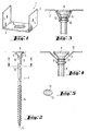
- Fig. 1 shows a perspective view of a fitting part 1, together with the fastening bolt seen in FIG. 2 forms the fastener according to the invention.
- the Fitting part 1 is made of sheet metal by stamping and bending, and has the shape of a U, in which the web 2 and the two adjoining legs 3 each are flat and the legs 3 with the web 2 one enclose right angle.
- the padding of the two Leg corresponds to the width of a usual ridge batten, whose thickness should be at least as high as the height of the Crosspieces 3.
- the ridge can be on the fitting part 1 be attached so that it is inserted between the webs and is pinned down there. To this end, the two point Put a mounting hole 4 on each.
- a funnel 5 coined, facing away from the legs 3 Side of the web 2 extends.
- a push-through opening 6 is formed, see also FIG. 2.
- a fastening bolt 7 inserted.
- the fastening bolt 7 is in Formed a screw with a countersunk head 8.
- Of the Countersunk head 8 has such a dimension that it in the Funnel shape 5 of the fitting part 3 can be accommodated.
- the edge of the opening 6 lies on the shaft 9 of the fastening bolt 7 on.
- the shaft 9 of the fastening bolt 7 has a certain Distance from the rib 10 on a key surface 13. This is made by cold shaping the shaft. It only slightly exceeds the circumference of the shaft 9, so that they push the fastening bolt 7 through the Opening 6 is not obstructed.
- the shaft 9 of the fastening bolt has in the area of the lower half 7 a double thread 14. This is enough up to the screw tip 11.
- the shape of the key surface 13 can be seen in FIG. 5 will.
- the section of the Screw shaft 9 is by cold forming according to Art made a bruise so that a section with two Flat wrench flats 13 running parallel to one another arises. A wrench can be attached to these key surfaces 13 can be scheduled. Sliding the wrench in both longitudinal directions of the fastening bolt 7 is prevented by the shaft 9 in the remaining area has a larger diameter than the distance of two key faces 13.
- FIG. 3 shows, in an enlarged cross section, one possibility of like the funnel shape 5 of the fitting part 1 to the shape of Fastening bolt is adjusted.
- the edge of the opening 6 lies on the top 12 of the circumferential rib 10, thus along a closed circular line. Lies at the same time the funnel in the area of its upper edge 15 on the underside of the screw head 8. This means that lengthways two closed circular lines create an attachment, so that the fitting is not during attachment tumbles too much.
- Fig. 4 shows an embodiment in which also the edge the opening 6 abuts the screw shaft 9, so that a Sealing along this circular line is given.
- the screw head 8 is not in contact with the funnel 5.
- the fastener shown in the figures is as follows used.
- the fastener is made in the Fig. 2 apparent form supplied.
- the fastening bolt is already inserted through the opening and the fitting part 3 is thereby fixed to the fastening bolt.
- the roofer uses a screwdriver to screw the fastening bolt 7 from above into the ridge purlin so far how this seems just right for his purpose, i.e. at a distance that he estimates.
- the fastening bolt shown in the figures can also can be used with other fittings, for example with a block of wood through which it is inserted.
- a fastening bolt could also be used 7 are used, the one is incomplete or weak thread, as is usually the case with screw nails. These are hammered hammered in, the screw nail thread only to do so serves a certain correction by turning forwards and backwards perform.
Landscapes
- Engineering & Computer Science (AREA)
- General Engineering & Computer Science (AREA)
- Architecture (AREA)
- Mechanical Engineering (AREA)
- Civil Engineering (AREA)
- Structural Engineering (AREA)
- Roof Covering Using Slabs Or Stiff Sheets (AREA)
- Joining Of Building Structures In Genera (AREA)
- Bulkheads Adapted To Foundation Construction (AREA)
- Connection Of Plates (AREA)
Abstract
Description
Bei hölzernen Dachstühlen wird der First des Dachstuhls von einer Firstpfette gebildet. Oberhalb der Firstpfette wird dann noch mit Abstand eine Firstlatte angebracht, die die Firstziegel tragen soll. Die Anbringung muß mit Abstand geschehen, da auf die Außenseite des Dachstuhls zunächst noch die Dachlatten und die Ziegel aufgebracht werden müssen. Die Firstlatte wird von dem Dachdecker befestigt. Bislang ist es üblich, hierzu ein U-förmiges Steckblech zu verwenden, dessen Abmessungen dem Querschnitt der Latte entsprechen. Dieses Steckblech wird mit Hilfe von durchgesteckten Nägeln angenagelt. Üblich ist auch ein U-förmiges Blech mit einem angeschweißten Nagel, ein sogenannter First- und Gratnagel. Der Abstand von der Firstpfette erfolgt nach Augenmaß des Dachdeckers bzw. nach Vorgabe des Ziegelherstellers.With wooden roof trusses, the ridge of the roof truss is from a ridge purlin. Above the ridge purlin then a ridge batten attached at a distance, which the Should carry ridge tiles. The attachment must be done at a distance, because on the outside of the roof structure initially the roof battens and the tiles must be applied. The The ridge is attached by the roofer. So far it is usual to use a U-shaped peg, the Dimensions correspond to the cross section of the crossbar. This The breadboard is nailed with the help of inserted nails. A U-shaped plate with a welded one is also common Nail, a so-called ridge and ridge nail. Of the Distance from the ridge purlin is according to the roofer's eye or according to the specifications of the brick manufacturer.
Diese Methode hat den Vorteil, daß nach Einlegen der Firstlatte und Anbringen der Ziegel die Firstlatte noch etwas der Firstpfette angenähert werden kann, indem der Dachdecker ein fach mit dem Hammer, den er sowieso bei sich führt, auf die Oberseite der Firstlatte im Bereich eines Nagels schlägt.This method has the advantage that after inserting the ridge and attaching the bricks to the ridge slat something else Ridge purlin can be approximated by the roofer fold with the hammer, which he carries with him anyway, on the Top of the ridge slats in the area of a nail.
Die Methode hat jedoch den Nachteil, daß ein zu tief eingeschlagenes Steckblech wieder herausgezogen werden muß. Dies bedeutet einen erhöhten Montageaufwand und der Halt geht verloren.However, the method has the disadvantage that it is too deep The plug-in plate must be pulled out again. This means an increased assembly effort and the hold is lost.
Es ist bereits ein höhenverstellbarer Lattenhalter für Dachstuhlkonstruktionen bekannt (DE-A1-39 33 037). Dieser enthält einen aus einem gebogenen Blechstreifen gebildeten Fuß und ein nach oben offenes U-förmiges Kopfstück, die durch eine Gewindestange miteinander verbunden sind. Der Abstand zwischen Kopfstück und Fuß kann vor dem Einlegen der Firstlatte in das Kopfstück verändert werden, nicht aber anschließend.It is already a height-adjustable slat holder for roof truss constructions known (DE-A1-39 33 037). This contains a foot formed from a bent sheet metal strip and an upwardly open U-shaped headpiece, which is separated by a Threaded rod are interconnected. The distance between The head piece and foot can be inserted before inserting the ridge be changed in the header, but not afterwards.
Weiterhin bekannt ist eine Halterung für eine Firstlatte (DE-C1-39 18 390), bei der ein mit einem Nagel zu befestigendes Kopfstück aus Holz besteht. Auf die Oberseite dieses Kopfstücks kann dann die Firstlatte angenagelt oder angeschraubt werden. Mit dieser Halterung ist eine Verstellung der Firstlatte zur Seite hin möglich, nicht aber eine Justierung ihres Abstandes von der Firstpfette.A holder for a ridge batten (DE-C1-39 18 390), in which one to be fastened with a nail Headpiece made of wood. On top of this head piece the ridge can then be nailed or screwed on will. With this bracket is an adjustment of the ridge possible to the side, but not an adjustment of yours Distance from the ridge purlin.
Der Erfindung liegt die Aufgabe zugrunde, eine Möglichkeit zu schaffen, wie mit geringem Aufwand eine Firstlatte nachträglich ausgerichtet werden kann, und zwar in beiden Richtungen, d.h. nach oben und nach unten.The invention has for its object a possibility create a ridge batten later with little effort can be aligned in both directions, i.e. up and down.
Zur Lösung dieser Aufgabe schlägt die Erfindung ein Befestigungselement
mit den im Anspruch 1 genannten Merkmalen vor.
Die Erfindung schlägt ebenfalls einen Befestigungsbolzen mit
den im Anspruch 11 genannten Merkmalen vor. Weiterbildungen
der Erfindung sind Gegenstand der jeweiligen abhängigen Ansprüche. To achieve this object, the invention proposes a fastener
with the features mentioned in
Die Befestigung der Firstlatte mit Hilfe des von der Erfindung vorgeschlagenen Befestigungselementes geschieht in fast der gleichen Weise wie bisher. Der Dachdecker befestigt das Beschlagteil mit Abstand an der Firstpfette nach Augenmaß. Anschließend kann er die Firstlatte an dem Beschlagteil anbringen. Er kann nun mit Hilfe beispielsweise eines einfachen Schraubenschlüssels an der Schlüsselfläche des Schaftes angreifen und eine Nachjustierung in beide Richtungen vornehmen. Er kann dies, ohne die Firstlatte abnehmen zu müssen, da die Verdrehung des Bolzenschaftes nicht durch Angriff an dem Kopf erfolgen muß. Beispielsweise kann der Schraubenschaft ein relativ steiles Doppelganggewinde aufweisen, so daß er den Befestigungsbolzen nur wenig verdrehen muß, um den Bolzen weiter ein- oder auszuschrauben.Fixing the ridge with the help of the invention proposed fastener happens in almost the same way as before. The roofer fixes that Fitting part at a distance on the ridge purlin by eye. He can then attach the ridge to the fitting. He can now, for example, with the help of a simple one Grip the wrench on the key surface of the shaft and readjust in both directions. He can do this without having to remove the ridge batten the torsion of the bolt shaft is not caused by attack on the Head must be done. For example, the screw shaft have a relatively steep double thread, so that it only has to twist the fastening bolt a little to the bolt continue to screw in or out.
Aufgrund der Möglichkeit der Nachjustierung selbst bei eingelegter Firstlatte braucht die erstmalige Befestigung nach Augenmaß nicht sehr sorgfältig geschehen, so daß sich hierdurch die Arbeitsgeschwindigkeit noch steigern läßt.Due to the possibility of readjustment even when the Firstlatte needs the first attachment Prosperity does not happen very carefully, so that this will can increase the speed of work.
Eine Möglichkeit, wie der Befestigungsbolzen ausgebildet sein kann, besteht darin, ihn als Schraube mit einem Senkkopf auszubilden. Dann kann der Handwerker sie beispielsweise mit einem Akku-Elektroschrauber einschrauben.One way in which the fastening bolt can be designed can be formed as a screw with a countersunk head. Then the craftsman can use them, for example screw in a cordless electric screwdriver.
Eine zweite Möglichkeit, die von der Erfindung vorgeschlagen wird, besteht darin, den Bolzen als Schraubnagel mit einem Senkkopf auszubilden. Dies hat den Vorteil, daß der Dachdecker die Befestigung, wie bisher üblich, mit dem Hammer vornehmen kann.A second possibility proposed by the invention is to use the bolt as a screw nail with a Form countersunk head. This has the advantage that the roofer the attachment, as usual, with the hammer can make.
Wenn das Beschlagteil an der Firstlatte formschlüssig oder kraftschlüssig festgelegt wird, wie bei den bisherigen Steckblechen, so kann eine Justierung mit Schraubwerkzeug auch erfolgen, wenn der Befestigungsbolzen einfach durch die Durchstecköffnung hindurchgesteckt ist. Unter Durchstecköffnung ist im übrigen eine Öffnung zu verstehen, die das Durchstecken des Befestigungsbolzens zwar ermöglicht, jedoch kann hierzu auch ein gewisser Aufwand erforderlich sein.If the fitting part on the ridge or is determined in a frictional manner, as with the previous plug-in plates, an adjustment with a screwing tool can also be carried out if the fastening bolt simply through the push-through opening is put through. Under push-through opening otherwise an opening is to be understood, which means pushing through of the fastening bolt allows, but can some effort may also be required for this.
In Weiterbildung der Erfindung kann vorgesehen sein, daß der Bolzen eine sein Herausziehen aus dem Beschlagteil behindernde Ausbildung aufweist. Da der Bolzen nur zum Teil in die Firstpfette eingeschlagen oder eingeschraubt wird, wird damit erreicht, daß das Beschlagteil am Kopf des Bolzens hängenbleibt, also nicht herabfällt.In a further development of the invention it can be provided that the Bolt a hindering his pulling out of the fitting part Training. Since the bolt is only partially in the Ridge purlin is hammered in or screwed in achieved that the fitting part gets caught on the head of the bolt, so don't fall down.
Insbesondere kann vorgesehen sein, daß der Bolzen unterhalb seines Kopfes eine Verdickung aufweist, insbesondere in Form eines umlaufenden Wulstes oder einer Rippe. Dieser Wulst kann einerseits zur Festlegung dienen, andererseits aber auch zur Abdichtung, so daß kein Wasser durch den Zwischenraum zwischen dem Bolzen und der Durchstecköffnung hindurchgelangen kann. Diese Abdichtung ist jedoch nicht unbedingt erforderlich.In particular, it can be provided that the bolt below has a thickened head, especially in shape of a circumferential bead or a rib. This bead can serve on the one hand to determine, on the other hand also for Sealing, so that no water through the space between the bolt and the push-through opening can. However, this seal is not absolutely necessary.
In Weiterbildung der Erfindung kann vorgesehen sein, daß das Beschlagteil im Bereich der Durchstecköffnung trichterförmig ausgebildet ist. Diese Trichterform läßt sich beim Herstellen des Beschlagteils in einfacher Weise mit herstellen.In a further development of the invention it can be provided that the Fitting part funnel-shaped in the area of the push-through opening is trained. This funnel shape can be made during manufacture of the fitting part in a simple manner.
Insbesondere kann vorgesehen sein, daß die Trichterform der Umgebung der Durchstecköffnung des Beschlagteils an die Kopfform des Bolzens angepaßt ist. Dies führt nicht nur zu einem besseren Verteilen der Kräfte, sondern insbesondere auch dazu, daß eine möglichst gute Abdichtung erreicht wird.In particular, it can be provided that the funnel shape of the Surrounding the push-through opening of the fitting part to the head shape the bolt is adjusted. This doesn't just lead to one better distribution of forces, but in particular also to that the best possible seal is achieved.
Erfindungsgemäß kann in Weiterbildung die Schlüsselfläche an dem Schaft durch Kaltverformen, beispielsweise Schlagen oder Pressen, hergestellt werden. Damit kann dafür gesorgt werden, daß die Kosten für das Befestigungselement niedrig gehalten werden. According to the invention, the key surface can be developed in a further development the shaft by cold working, for example hitting or Pressing. This can ensure that the cost of the fastener is kept low will.
Insbesondere kann vorgesehen sein, daß das Beschlagteil aus Blech besteht, beispielsweise mit einer U-Form, die der Querschnittsform üblicher Firstlatten angepaßt ist. Dabei ist die Durchstecköffnung im Steg des U angeordnet, insbesondere mittig. Die Schenkel können ebenfalls Löcher aufweisen, durch die hindurch der Dachdecker die Firstlatte an dem Beschlagteil annageln kann. Die Erfindung schlägt ebenfalls einen Befestigungsbolzen vor, der insbesondere aber nicht ausschließlich zusammen mit dem Beschlagteil zur Befestigung von Firstlatten dient.In particular, it can be provided that the fitting part Sheet metal exists, for example with a U-shape, that of the cross-sectional shape usual ridge slats is adapted. Here is the Push-through opening arranged in the web of the U, in particular in the middle. The legs can also have holes through through which the roofer fixed the ridge on the fitting part can nail on. The invention also proposes a fastening bolt before, especially but not exclusively together with the fitting part for fastening ridge battens serves.
Weitere Merkmale, Einzelheiten und Vorzüge ergeben sich aus den Patentansprüchen, deren Wortlaut durch Bezugnahme zum Inhalt der Beschreibung gemacht wird, der folgenden Beschreibung einer bevorzugten Ausführungsform der Erfindung sowie anhand der Zeichnung. Hierbei zeigen:
- Fig. 1
- perspektivisch eine Ansicht eines einen Teil des Befestigungselementes dienenden Beschlagteils;
- Fig. 2
- eine Ansicht des in dem abgebrochen dargestellten Beschlagteil eingesetzten Befestigungsbolzens;
- Fig. 3
- in vergrößertem Maßstab einen Teilschnitt durch das Beschlagteil im Bereich der Durchstecköffnung;
- Fig. 4
- eine der Fig. 3 entsprechende Darstellung bei einer leicht geänderten Ausführungsform;
- Fig. 5
- einen Querschnitt längs Linie V-V in Fig. 2 durch die Schlüsselfläche des Befestigungsbolzens.
- Fig. 1
- a perspective view of a fitting part serving as part of the fastening element;
- Fig. 2
- a view of the mounting bolt used in the broken fitting shown;
- Fig. 3
- on an enlarged scale, a partial section through the fitting part in the area of the push-through opening;
- Fig. 4
- a representation corresponding to Figure 3 in a slightly modified embodiment.
- Fig. 5
- a cross section along line VV in Fig. 2 by the key surface of the fastening bolt.
Fig. 1 zeigt perspektivisch die Ansicht eines Beschlagteils
1, das zusammen mit dem in Fig. 2 zu sehenden Befestigungsbolzen
das Befestigungselement nach der Erfindung bildet. Das
Beschlagteil 1 ist aus Blech durch Stanzen und Biegen hergestellt,
und weist die Form eines U auf, bei dem der Steg 2
und die beiden sich daran anschließenden Schenkel 3 jeweils
eben ausgebildet sind und die Schenkel 3 mit dem Steg 2 einen
rechten Winkel einschließen. Der Innenabstand der beiden
Schenkel entspricht dabei der Breite einer üblichen Firstlatte,
deren Dicke mindestens so hoch sein soll wie die Höhe der
Stege 3. Die Firstlatte kann an dem Beschlagteil 1 dadurch
befestigt werden, daß sie zwischen die Stege eingelegt wird
und dort festgenagelt wird. Zu diesem Zweck weisen die beiden
Stege je ein Befestigungsloch 4 auf.Fig. 1 shows a perspective view of a
In der Mitte des Steges 2 des Beschlagteils 1 ist ein Trichter
5 geprägt, der sich zu der den Schenkeln 3 abgewandten
Seite des Steges 2 hin erstreckt. In der Mitte des Trichters
5 ist eine Durchstecköffnung 6 gebildet, siehe auch Fig. 2.In the middle of the
In Fig. 2, die das Beschlagteil 1 nur teilweise zeigt, ist in
die Durchstecköffnung 6 am Boden des Trichters 5 ein Befestigungsbolzen
7 eingesteckt. Der Befestigungsbolzen 7 ist in
Form einer Schraube mit einem Senkkopf 8 ausgebildet. Der
Senkkopf 8 weist eine solche Abmessung auf, daß er in der
Trichterform 5 des Beschlagteils 3 untergebracht werden kann.
Der Rand der Öffnung 6 liegt an dem Schaft 9 des Befestigungsbolzens
7 an.2, which shows the
Mit einem gewissen Abstand unterhalb des Senkkopfes 8 weist
der Befestigungsbolzen 7 in seinem Schaft 9 eine umlaufende,
im Querschnitt dreieckige Rippe 10 auf. Die zur Schraubenspitze
11 gerichtete Unterseite der Rippe 10 verläuft schräg,
während die Oberseite 12 fast rechtwinklig zur Schraubenlängsachse
verläuft. Die Rippe 10 verhindert einerseits das
Herabfallen des Beschlagteils 1 an dem Schaft 9 und bildet
andererseits eine Anlagefläche für den Rand der Öffnung 6,
die zur Abdichtung dienen kann.With a certain distance below the countersunk
Der Schaft 9 des Befestigungsbolzens 7 weist mit einem gewissen
Abstand von der Rippe 10 eine Schlüsselfläche 13 auf.
Diese ist durch ein Kaltverformen des Schaftes hergestellt.
Sie überragt den Umfang des Schaftes 9 nur unwesentlich, so
daß sie das Durchschieben des Befestigungsbolzens 7 durch die
Öffnung 6 nicht behindert.The
Im Bereich der unteren Hälfte weist der Schaft 9 des Befestigungsbolzens
7 ein Doppelganggewinde 14 auf. Dieses reicht
bis zur Schraubenspitze 11.The
Die Form der Schlüsselfläche 13 kann der Fig. 5 entnommen
werden. Der die Schlüsselfläche 13 aufweisende Abschnitt des
Schraubenschaftes 9 ist durch ein Kaltverformen nach Art
einer Quetschung hergestellt, so daß ein Abschnitt mit zwei
parallel zueinander verlaufenden, ebenen Schlüsselflächen 13
entsteht. An diesen Schlüsselflächen 13 kann ein Schraubenschlüssel
angesetzt werden. Das Abgleiten des Schraubenschlüssels
in beiden Längsrichtungen des Befestigungsbolzens
7 wird dadurch verhindert, daß der Schaft 9 im übrigen Bereich
einen größeren Durchmesser aufweist als der Abstand der
beiden Schlüsselflächen 13.The shape of the
Fig. 3 zeigt in vergrößertem Querschnitt eine Möglichkeit,
wie die Trichterform 5 des Beschlagteils 1 an die Form des
Befestigungsbolzens angepaßt ist. Der Rand der Öffnung 6
liegt dabei auf der Oberseite 12 der umlaufenden Rippe 10 an,
also längs einer geschlossenen Kreislinie. Gleichzeitig liegt
der Trichter im Bereich seines oberen Randes 15 an der Unterseite
des Schraubenkopfes 8 an. Dies bedeutet, daß längs
zweier geschlossener kreisförmiger Linien eine Anlage erfolgt,
so daß das Beschlagteil während der Befestigung nicht
zu stark taumelt.3 shows, in an enlarged cross section, one possibility of
like the
Fig. 4 zeigt eine Ausführungsform, bei der ebenfalls der Rand
der Öffnung 6 an dem Schraubenschaft 9 anliegt, so daß eine
Abdichtung längs dieser kreisförmigen Linie gegeben ist. Dagegen
liegt der Schraubenkopf 8 nicht an dem Trichter 5 an.
Beide Ausführungsformen sind für den Zweck der Erfindung geeignet,
wobei die Ausführungsform nach Fig. 3 die bevorzugte
ist.Fig. 4 shows an embodiment in which also the edge
the
Das in den Figuren dargestellte Befestigungselement wird folgendermaßen
benutzt. Das Befestigungselement wird in der aus
Fig. 2 ersichtlichen Form geliefert. Der Befestigungsbolzen
ist also schon durch die Öffnung hindurchgesteckt und das Beschlagteil
3 ist an dem Befestigungsbolzen dadurch festgelegt.
Der Dachdecker schraubt mit einem Schrauber den Befestigungsbolzen
7 von oben her in die Firstpfette so weit ein,
wie ihm dies für seinen Zweck gerade richtig erscheint, d.h.
mit einem Abstand, den er abschätzt.The fastener shown in the figures is as follows
used. The fastener is made in the
Fig. 2 apparent form supplied. The fastening bolt
is already inserted through the opening and the
Nach dem Anbringen aller Befestigungselemente längs der
Firstpfette legt er die Firstlatte zwischen die Schenkel 3
des Beschlagteils 1 ein und nagelt dieses fest. Anschließend
reguliert er mit einem Schraubenschlüssel, den er an den
Schlüsselflächen 13 ansetzt, den korrekten Abstand der Firstlatte
von der Firstpfette ein. Er kann dabei den Abstand verkleinern
oder vergrößern.After attaching all fasteners along the
He places the ridge purlin between the
Der in den Figuren dargestellte Befestigungsbolzen kann auch mit anderen Beschlagteilen verwendet werden, beispielsweise mit einem Holzklotz, durch den er hindurchgesteckt ist.The fastening bolt shown in the figures can also can be used with other fittings, for example with a block of wood through which it is inserted.
Anstelle des Doppelganggewindes 14, das ein vollständig ausgewalztes,
scharfkantiges Gewinde ist, könnte auch ein Befestigungsbolzen
7 verwendet werden, der ein nur unvollständig
bzw. schwach ausgebildetes Gewinde aufweist, wie man es üblicherweise
bei Schraubnägeln findet. Diese werden mit dem Hammer
eingeschlagen, wobei das Schraubnagelgewinde nur dazu
dient, noch eine gewisse Korrektur durch Vorwärts- und Rückwärtsdrehen
durchzuführen.Instead of the
Claims (12)
- 1.1
- einem an der Firstlatte festlegbaren Beschlagteil (1), das
- 1.1.1
- eine Durchstecköffnung (6) aufweist, sowie mit
- 1.2
- einem Befestigungsbolzen (7), der
- 1.2.1
- durch die Durchstecköffnung (6) des Beschlagteils (1) hindurchgesteckt wird,
- 1.2.2
- einen Kopf (8) und
- 1.2.3
- einen Schaft (9) aufweist, wobei
- 1.3
- der Schaft (9) ein Gewinde (14) und
- 1.3.1
- im Bereich zwischen dem Kopf (8) und dem Gewinde (14) eine bei an der Firstlatte befestigtem Beschlagteil (1) zugängliche Schlüsselfläche (13) aufweist, zur Verstellung des Abstands zwischen Firstlatte und Firstpfette.
- 1.1
- a fitting part (1) which can be fixed on the ridge batten
- 1.1.1
- has a push-through opening (6), and with
- 1.2
- a mounting bolt (7), the
- 1.2.1
- is pushed through the push-through opening (6) of the fitting part (1),
- 1.2.2
- a head (8) and
- 1.2.3
- has a shaft (9), wherein
- 1.3
- the shaft (9) has a thread (14) and
- 1.3.1
- in the area between the head (8) and the thread (14) has a key surface (13) accessible when the fitting part (1) is fastened to the ridge batten, for adjusting the distance between the ridge batten and the ridge purlin.
Applications Claiming Priority (2)
| Application Number | Priority Date | Filing Date | Title |
|---|---|---|---|
| DE19632743A DE19632743A1 (en) | 1996-08-14 | 1996-08-14 | Fastening element for attaching a ridge and fastening bolts for this |
| DE19632743 | 1996-08-14 |
Publications (1)
| Publication Number | Publication Date |
|---|---|
| EP0824173A1 true EP0824173A1 (en) | 1998-02-18 |
Family
ID=7802600
Family Applications (1)
| Application Number | Title | Priority Date | Filing Date |
|---|---|---|---|
| EP97113541A Withdrawn EP0824173A1 (en) | 1996-08-14 | 1997-08-06 | Fastening element and its use for connecting a ridge batten and fastening bolt therefore |
Country Status (7)
| Country | Link |
|---|---|
| EP (1) | EP0824173A1 (en) |
| BG (1) | BG62705B1 (en) |
| CZ (1) | CZ249497A3 (en) |
| DE (1) | DE19632743A1 (en) |
| NO (1) | NO973721L (en) |
| PL (1) | PL321578A1 (en) |
| SK (1) | SK109697A3 (en) |
Cited By (6)
| Publication number | Priority date | Publication date | Assignee | Title |
|---|---|---|---|---|
| FR2922924A1 (en) * | 2007-10-30 | 2009-05-01 | Sarl Francois Inglese Sarl | Support rails fixing device for building, has large length sectioned rod with zones, where one zone is extended from flat spot and threaded for receiving U-profiled rider with flanges that are slotted for fixing rider on support rail |
| WO2011042200A1 (en) * | 2009-10-09 | 2011-04-14 | Hans Wastl | Fitting for adjusting a distance between a component and a substructure and a system and method therefor |
| WO2016091863A1 (en) * | 2014-12-12 | 2016-06-16 | Eaton Electrical Ip Gmbh & Co. Kg | Screw, in particular for housings |
| CN106030127A (en) * | 2014-02-22 | 2016-10-12 | 奥迪股份公司 | Fastening device for tamper-proof fastening, and component assembly |
| PL131542U1 (en) * | 2023-07-06 | 2025-01-07 | Promamet Spółka Z Ograniczoną Odpowiedzialnością | Ridge batten bracket |
| PL132070U1 (en) * | 2024-03-26 | 2025-09-29 | Promamet Spółka Z Ograniczoną Odpowiedzialnością | Ridge batten bracket |
Families Citing this family (4)
| Publication number | Priority date | Publication date | Assignee | Title |
|---|---|---|---|---|
| DE10046041C1 (en) * | 2000-09-18 | 2002-08-22 | Fassaden Praktiker Ost West Ve | Ridge or ridge slat holder |
| DE10056506A1 (en) * | 2000-11-15 | 2002-05-29 | Duve Umformtechnik Gmbh | Screw for fastening ridge board at distance above point of roof truss has threaded top and bottom sections separated by narrower, intermediate threaded section, which is longer than thickness of ridge board |
| DE10220284C1 (en) * | 2001-12-20 | 2003-08-28 | Matrix Vertriebs Service Gmbh | Building component used as a roof lath holder comprises a retaining device with elastic properties provided in the region of a through hole to form a trap for the head of a fixing part |
| DE102010030893A1 (en) * | 2010-07-02 | 2012-01-05 | Reisser Schraubentechnik Gmbh | Screw for attaching pre-punched metal sheet to plastic material, has sharp edged radially running ribs formed at bottom of screw head, where steep edge of ribs is forwardly and rearwardly directed in screw-in direction of screw threads |
Citations (1)
| Publication number | Priority date | Publication date | Assignee | Title |
|---|---|---|---|---|
| DE3427608A1 (en) * | 1984-06-14 | 1985-12-19 | ROTAN GmbH Holztechnik, 8121 Polling | SUB-CONSTRUCTION COMPENSATION SCREW |
Family Cites Families (6)
| Publication number | Priority date | Publication date | Assignee | Title |
|---|---|---|---|---|
| DE3435434A1 (en) * | 1984-09-27 | 1986-04-10 | Erich 6728 Germersheim Lutz | Spacing/adjusting wood screw connector |
| DE3441561A1 (en) * | 1984-11-14 | 1986-05-22 | Franz 6200 Wiesbaden Müller | Shoulder screw or vice screw |
| DE3933037A1 (en) * | 1988-11-14 | 1990-05-17 | Oskar Fleck | Support for roof ridge beam - enables height of beam to be adjusted relative to roof truss |
| DE3918390C1 (en) * | 1989-06-06 | 1990-06-07 | Braas & Co Gmbh, 6370 Oberursel, De | Ridge batten for building - is fixed by nail and head made of block of laminated wood |
| DE4001971A1 (en) * | 1990-01-24 | 1991-07-25 | Itw Ateco Gmbh | Self-drilling screw for sheet metal - has tapering expander portion and parallel one both with fine thread |
| DE9405413U1 (en) * | 1994-03-30 | 1994-06-01 | Albert Graf Gmbh & Co. Kg, 58762 Altena | Screw for driving into an expansion anchor |
-
1996
- 1996-08-14 DE DE19632743A patent/DE19632743A1/en not_active Withdrawn
-
1997
- 1997-08-06 EP EP97113541A patent/EP0824173A1/en not_active Withdrawn
- 1997-08-06 CZ CZ972494A patent/CZ249497A3/en unknown
- 1997-08-11 SK SK1096-97A patent/SK109697A3/en unknown
- 1997-08-12 PL PL97321578A patent/PL321578A1/en unknown
- 1997-08-13 NO NO973721A patent/NO973721L/en not_active Application Discontinuation
- 1997-08-13 BG BG101828A patent/BG62705B1/en unknown
Patent Citations (2)
| Publication number | Priority date | Publication date | Assignee | Title |
|---|---|---|---|---|
| DE3427608A1 (en) * | 1984-06-14 | 1985-12-19 | ROTAN GmbH Holztechnik, 8121 Polling | SUB-CONSTRUCTION COMPENSATION SCREW |
| EP0219556A1 (en) * | 1984-06-14 | 1987-04-29 | ROTAN GmbH Holztechnik | Adjusting screw for a substructure |
Cited By (9)
| Publication number | Priority date | Publication date | Assignee | Title |
|---|---|---|---|---|
| FR2922924A1 (en) * | 2007-10-30 | 2009-05-01 | Sarl Francois Inglese Sarl | Support rails fixing device for building, has large length sectioned rod with zones, where one zone is extended from flat spot and threaded for receiving U-profiled rider with flanges that are slotted for fixing rider on support rail |
| WO2011042200A1 (en) * | 2009-10-09 | 2011-04-14 | Hans Wastl | Fitting for adjusting a distance between a component and a substructure and a system and method therefor |
| CN106030127A (en) * | 2014-02-22 | 2016-10-12 | 奥迪股份公司 | Fastening device for tamper-proof fastening, and component assembly |
| US9995332B2 (en) | 2014-02-22 | 2018-06-12 | Audi Ag | Fastening device for tamper-proof fastening, and component arrangement |
| WO2016091863A1 (en) * | 2014-12-12 | 2016-06-16 | Eaton Electrical Ip Gmbh & Co. Kg | Screw, in particular for housings |
| CN107002737A (en) * | 2014-12-12 | 2017-08-01 | 伊顿电气Ip两合公司 | Particularly for the screw of housing |
| US10520003B2 (en) | 2014-12-12 | 2019-12-31 | Eaton Intelligent Power Limited | Screw suitable for housings |
| PL131542U1 (en) * | 2023-07-06 | 2025-01-07 | Promamet Spółka Z Ograniczoną Odpowiedzialnością | Ridge batten bracket |
| PL132070U1 (en) * | 2024-03-26 | 2025-09-29 | Promamet Spółka Z Ograniczoną Odpowiedzialnością | Ridge batten bracket |
Also Published As
| Publication number | Publication date |
|---|---|
| NO973721L (en) | 1998-02-16 |
| DE19632743A1 (en) | 1998-02-19 |
| BG62705B1 (en) | 2000-05-31 |
| CZ249497A3 (en) | 1998-05-13 |
| NO973721D0 (en) | 1997-08-13 |
| PL321578A1 (en) | 1998-02-16 |
| BG101828A (en) | 1998-03-31 |
| SK109697A3 (en) | 1998-07-08 |
Similar Documents
| Publication | Publication Date | Title |
|---|---|---|
| DE2618442C2 (en) | Support for a railing or the like | |
| EP2009293A2 (en) | Device for connecting a profile rail with another component | |
| WO2000034670A1 (en) | T-link between two profile bars | |
| EP0307647A1 (en) | Washer | |
| DE20015537U1 (en) | Roof and ceiling system | |
| AT404380B (en) | DEVICE, IN PARTICULAR DISTANCE ANCHOR FOR ADJUSTMENT AND FASTENING OF FRAME | |
| AT392331B (en) | FASTENING ELEMENT FOR FIXING INSULATING SHEETS OR PANELS ON A FIXED BASE | |
| EP2756238B1 (en) | Device for fastening a mounting rail on a roof hook | |
| EP0824173A1 (en) | Fastening element and its use for connecting a ridge batten and fastening bolt therefore | |
| EP1175567B1 (en) | Fixing element for fixing insulating strips or plates on a solid substructure | |
| DE2451813A1 (en) | Door frame fastener on masonry - has bracket with bent ends fitted into groove on frame masonry side | |
| EP1035294B1 (en) | Assembly kit for a mullion within a frame | |
| AT500181B1 (en) | DOOR OR WINDOW FITTING | |
| EP1126099A2 (en) | Fastening device for panel-like façade elements | |
| DE3333055A1 (en) | Device for fastening laths | |
| DE3611873A1 (en) | Fastening element for the adjustable fastening of structural elements on structures | |
| EP1754841A2 (en) | Insulating profile | |
| EP1469157B1 (en) | Lock profile | |
| EP1199481A1 (en) | Cross linkage for profile bars | |
| DE19641065C1 (en) | Adjustable ridge or hip batten holder for roof trusses | |
| DE4000504A1 (en) | Attachment of handrail or facade to wall - involves use of rail with elongated hole with serrated edges | |
| DE3128505A1 (en) | Device for the junction connection of wooden framework bars | |
| DE2801961A1 (en) | Fixture element for grooved cladding panels - has fish-plate bent out of matching section plane, with pointed spike at right angles | |
| WO1982000690A1 (en) | Anchoring bolt | |
| DE4013690A1 (en) | Pipe fixture clamp for downpipes - has tie bolt and two curved clamp parts each with curved piece and clamping arm |
Legal Events
| Date | Code | Title | Description |
|---|---|---|---|
| PUAI | Public reference made under article 153(3) epc to a published international application that has entered the european phase |
Free format text: ORIGINAL CODE: 0009012 |
|
| AK | Designated contracting states |
Kind code of ref document: A1 Designated state(s): AT BE CH DE DK ES FI FR GB GR IE IT LI LU MC NL PT SE |
|
| AX | Request for extension of the european patent |
Free format text: AL PAYMENT 970805;RO PAYMENT 970805;SI PAYMENT 970805 |
|
| 17P | Request for examination filed |
Effective date: 19980729 |
|
| AKX | Designation fees paid |
Free format text: AT BE CH DE DK ES FI FR GB GR IE IT LI LU MC NL PT SE |
|
| AXX | Extension fees paid |
Free format text: AL PAYMENT 970805;RO PAYMENT 970805;SI PAYMENT 970805 |
|
| RBV | Designated contracting states (corrected) |
Designated state(s): AT BE CH DE DK ES FI FR GB GR IE IT LI LU MC NL PT SE |
|
| STAA | Information on the status of an ep patent application or granted ep patent |
Free format text: STATUS: THE APPLICATION IS DEEMED TO BE WITHDRAWN |
|
| 18D | Application deemed to be withdrawn |
Effective date: 20010301 |