EP0709063A1 - Ophthalmic surgical instrument - Google Patents
Ophthalmic surgical instrument Download PDFInfo
- Publication number
- EP0709063A1 EP0709063A1 EP95116528A EP95116528A EP0709063A1 EP 0709063 A1 EP0709063 A1 EP 0709063A1 EP 95116528 A EP95116528 A EP 95116528A EP 95116528 A EP95116528 A EP 95116528A EP 0709063 A1 EP0709063 A1 EP 0709063A1
- Authority
- EP
- European Patent Office
- Prior art keywords
- actuator
- tool
- instrument
- actuation surface
- handle
- Prior art date
- Legal status (The legal status is an assumption and is not a legal conclusion. Google has not performed a legal analysis and makes no representation as to the accuracy of the status listed.)
- Withdrawn
Links
- 210000003811 finger Anatomy 0.000 description 16
- 210000003813 thumb Anatomy 0.000 description 10
- 238000003825 pressing Methods 0.000 description 6
- 230000000717 retained effect Effects 0.000 description 3
- 210000004369 blood Anatomy 0.000 description 2
- 239000008280 blood Substances 0.000 description 2
- 210000001124 body fluid Anatomy 0.000 description 2
- 239000010839 body fluid Substances 0.000 description 2
- 238000004140 cleaning Methods 0.000 description 2
- 238000006073 displacement reaction Methods 0.000 description 2
- 230000035807 sensation Effects 0.000 description 2
- 238000001356 surgical procedure Methods 0.000 description 2
- 229920006362 Teflon® Polymers 0.000 description 1
- 230000003321 amplification Effects 0.000 description 1
- 230000006835 compression Effects 0.000 description 1
- 238000007906 compression Methods 0.000 description 1
- 238000010276 construction Methods 0.000 description 1
- 230000007797 corrosion Effects 0.000 description 1
- 238000005260 corrosion Methods 0.000 description 1
- 230000000881 depressing effect Effects 0.000 description 1
- 230000000994 depressogenic effect Effects 0.000 description 1
- 210000004247 hand Anatomy 0.000 description 1
- 238000003199 nucleic acid amplification method Methods 0.000 description 1
- 238000005096 rolling process Methods 0.000 description 1
Images


Classifications
-
- A—HUMAN NECESSITIES
- A61—MEDICAL OR VETERINARY SCIENCE; HYGIENE
- A61B—DIAGNOSIS; SURGERY; IDENTIFICATION
- A61B17/00—Surgical instruments, devices or methods
- A61B17/28—Surgical forceps
- A61B17/29—Forceps for use in minimally invasive surgery
- A61B17/2909—Handles
-
- A—HUMAN NECESSITIES
- A61—MEDICAL OR VETERINARY SCIENCE; HYGIENE
- A61B—DIAGNOSIS; SURGERY; IDENTIFICATION
- A61B17/00—Surgical instruments, devices or methods
- A61B2017/0046—Surgical instruments, devices or methods with a releasable handle; with handle and operating part separable
-
- A—HUMAN NECESSITIES
- A61—MEDICAL OR VETERINARY SCIENCE; HYGIENE
- A61B—DIAGNOSIS; SURGERY; IDENTIFICATION
- A61B17/00—Surgical instruments, devices or methods
- A61B17/28—Surgical forceps
- A61B17/29—Forceps for use in minimally invasive surgery
- A61B17/2909—Handles
- A61B2017/2912—Handles transmission of forces to actuating rod or piston
- A61B2017/2918—Handles transmission of forces to actuating rod or piston flexible handles
-
- A—HUMAN NECESSITIES
- A61—MEDICAL OR VETERINARY SCIENCE; HYGIENE
- A61B—DIAGNOSIS; SURGERY; IDENTIFICATION
- A61B17/00—Surgical instruments, devices or methods
- A61B17/28—Surgical forceps
- A61B17/29—Forceps for use in minimally invasive surgery
- A61B17/2909—Handles
- A61B2017/2912—Handles transmission of forces to actuating rod or piston
- A61B2017/2919—Handles transmission of forces to actuating rod or piston details of linkages or pivot points
- A61B2017/292—Handles transmission of forces to actuating rod or piston details of linkages or pivot points connection of actuating rod to handle, e.g. ball end in recess
-
- A—HUMAN NECESSITIES
- A61—MEDICAL OR VETERINARY SCIENCE; HYGIENE
- A61B—DIAGNOSIS; SURGERY; IDENTIFICATION
- A61B17/00—Surgical instruments, devices or methods
- A61B17/30—Surgical pincettes, i.e. surgical tweezers without pivotal connections
- A61B2017/305—Tweezer like handles with tubular extensions, inner slidable actuating members and distal tools, e.g. microsurgical instruments
Definitions
- the invention relates to handheld tools, and more specifically relates to handheld tools of the mechanically operable type. In its most immediate sense, the invention relates to ophthalmic surgical instruments of the Sutherland type.
- Eye surgery requires the use of forceps, scissors etc. within the eye.
- a surgeon will make an incision in the eye and will then introduce a surgical instrument, e.g. a scissors, in the incision. The surgeon will then operate the scissors by actuating the tool.
- a surgical instrument e.g. a scissors
- a Sutherland-type instrument has a pen-type handle and uses a lever as an actuator.
- a variety of mechanically operable spring-loaded tools e.g. scissors, forceps, knives etc. can be threaded onto the front tip of the handle immediately adjacent the lever.
- a surgeon operates the tool (i.e. opens and closes the forceps or scissors) by depressing the lever using his thumb or index finger. Such depression operates the tool against the pressure of its internal spring. After operating the tool, the surgeon releases the lever arm, causing the tool to return to its original state.
- This type of surgical instrument has disadvantages.
- One such disadvantage is that keeping the instrument in the operated state (e.g. keeping a forceps in the closed position) while rotating the tool 180° often forces the surgeon to assume an awkward posture and/or to use two hands when only one hand is conveniently free.
- Another disadvantage is that the instrument cannot conveniently be operated in all rotational positions, i.e. the tool cannot easily be operated unless the lever arm is e.g. adjacent the surgeon's index finger.
- Sutherland-type instrument which could be used to operate tools designed to fit with existing Sutherland-type instruments, but which additionally would be suitable for operation in all rotational positions and which could be easily and conveniently rotated about its axis even when in the operated state.
- the actuator of a pen-type instrument is located at the end of an elongated handle.
- the actuator has an actuation surface which extends completely around the axis of the handle.
- the actuator is operated by applying pressure anywhere on this actuation surface. Because the actuation surface can be actuated at any point, there is no need to position an actuator lever adjacent the surgeon's index finger or thumb, and there is no difficulty in rotating the instrument while the actuator is operated.
- the actuator has a mechanical advantage which is greater than unity, i.e. a small movement of the actuator causes a larger movement of the tool. This amplifies a surgeon's relatively small squeezing or pressing motion to a relatively large motion of the threaded-on tool.
- a Sutherland-type instrument system such as is sold in the United States through Grieshaber & Co., Inc. (see Fig. 1), such tools 2 are detachably securable to the threaded end of a handle 4.
- the handle 4 is provided with an actuator 6 which takes the form of a pivoted lever having an interior end (not shown, for operating the tool) and an exterior end 8 (for operation by the surgeon's thumb or index finger).
- an interior spring-loaded plunger (not shown) in the tool 2 is urged against the interior end of the actuator 6.
- the surgeon when the instrument is lying on a work surface and the surgeon wishes to use it, the surgeon must not only rotate the instrument to a position in which the lever is in the proper position but must also rotate the tool 2 itself so that the tool 2 is properly oriented.
- the tool 2 is a scissors which is oriented at 12:00 in the instrument tray (not shown).
- the surgeon wishes to use the scissors at the 3:00 orientation. To do this, the surgeon must pick up the instrument, revolve it in his hand until the instrument is in a comfortable position and then spin the tool 2 to the 3:00 orientation while holding the handle 4 fixed.
- a pen-type instrument has an elongated handle 4' with an actuator 6' at one end.
- the actuator 6' has an actuation surface 10 which extends completely around the axis 12 of the handle 4'; advantageously, the actuation surface 10 is generally cylindrical and coaxial with the axis 12 of the handle 4'.
- the actuation surface 10 is an elastomeric boot 12 which seals the actuator 6' and prevents foreign matter from entering and obstructing the mechanism.
- the actuator 6' is operated by applying pressure anywhere on the actuation surface 10.
- a surgeon who picks up the instrument with the actuator 6' between his thumb and index finger can easily and conveniently rotate the tool whether it is in the operated or unoperated state. Such rotation is easily accomplished by rolling the actuator 6' between the thumb and index finger; operation and release of the tool 2 is easily accomplished by respectively squeezing and releasing the actuator 6'. It is alternatively possible to operate the actuator 6' by holding the handle 4' and pressing the actuation surface 10 of the actuator 6' with the thumb or index finger.
- a central axially elongated rod 14 supports a nose piece 16, which is fixed to the forward end 18 of the rod 14.
- Six triggers 20 (for clarity, only one is shown in Figs. 3 and 4) are pivotally secured to the nose piece 16.
- Each trigger 20 has a pivot end 20P, a free end 20F and a tie arm 20T; each tie arm 20T is curved to circulate around the rod 14, and each tie arm 20T has a hook 20H at its distal end (see Fig. 3A).
- the boot 12 fits over the nose piece 16 and triggers 20 and is sufficiently elastic to permit the triggers 20 to move radially inwardly and outwardly.
- a trigger retainer 22 is slidably mounted upon the rod 14.
- the trigger retainer 22 is a hollow sleeve which has an annular grooved region 24 on its radially outer surface.
- the grooved region 24 receives the hooks 20H at the ends of the six tie arms 20T from the six triggers 20; the hook 20H from each tie arm 20T is disposed within the grooved region 24.
- Each trigger 20 is pivotally mounted at its pivot end 20P to the nose piece 16.
- the hook 20H at the end of the tie arm 20T presses against the grooved region 24 and urges the trigger retainer 22 to the right as viewed in Figs. 3 and 4. This causes all the triggers 20 to simultaneously move radially inwardly.
- spring pressure urges the trigger retainer 22 to the left as viewed in Figs. 3 and 4
- the free ends 20F of all the triggers 20 are simultaneously moved radially outwardly, away from the rod 14. It may therefore be understood that radially inward and outward motion of any one of the triggers 20 is converted respectively to rightward and leftward translation of the trigger retainer 22 and is accompanied by like simultaneous movement of all the other triggers 20.
- the rod 14 has an axially extending bore 26 which is open at the forward end 28 and which extends rearwardly from the forward end 28.
- the rod 14 also has an axially elongated slot 30 which passes entirely through the rod 14 and which intersects the bore 26 near its bottom.
- a pin 32 is secured to the trigger retainer 22 (as by force-fitting into two diametrically opposed holes) and passes through the slot 30 so as to extend radially with respect to the rod 14.
- a slide piston 34 is located within the bore 26.
- the slide piston 34 has an enlarged rear end 34R which fits closely within the bore 26 and is located just forwardly of the pin 32.
- the enlarged rear end 34R of the slide piston 34 insures that the slide piston 34 slides back and forth within the bore 26 and does not become wedged in position as a result of misalignment.
- the front end 34F of the slide piston 34 is cut down and an O-ring 36 (of e.g. Teflon®) is located at the front end 34F of the slide piston 34. This seals the mechanism and prevents foreign matter (e.g. blood, body fluids etc.) from entering from the open front end 28 of the rod 14.
- the invention is designed for use with a spring-loaded tool 2 which is threaded onto the threaded forward end 28 of the rod 14.
- This spring pressure always urges the slide piston 34 to the left as viewed in Figs. 3 and 4. Consequently, when a tool 2 has been attached to the forward end 28 of the actuator 6', the slide piston 34 and the pin 32 are always pressed together and a movement of one part will cause all other parts to move as well.
- the triggers 20 use elongated tie arms 20T because this produces substantial translational movement of the trigger retainer 22 and slide piston 34 with only slight rotation of the triggers 20.
- the movement of the slide piston 34 is considered to be sufficient to operate any tool 2 which may be connected to the actuator 6'.
- an alternate embodiment exists which amplifies the translational movement of the piston 32 with respect to the translational movement of the trigger retainer 22. This alternate embodiment will now be described with reference to Figs. 5 and 6.
- the boot (not shown, but identical to the boot 12) surrounding the actuator 6' conceals from view two sets of mechanical components.
- the first set is very similar to the structure of the preferred embodiment of the invention; this set of components converts radial motion of the triggers 20 into linear translation motion within the actuator 6'.
- this translation motion is amplified to provide motion which is adequate to operate any attached tool 2.
- the first set will be briefly described first, and the second set will be described next.
- a central axially elongated rod 14' (the rod 14' is identical to the rod 14 in the preferred embodiment) supports a nose piece 16', which is fixed to the forward end 28' of the rod 14'.
- Six triggers 20' (for clarity, only one is shown in Figs. 5 and 6) are pivotally secured to the nose piece 16'.
- the triggers 20' are the same as the triggers 20 in the preferred embodiment, and each trigger 20' has a pivot end 20P', a free end 20F' and a tie arm 20T'; each tie arm 20T' is curved to circulate around the rod 14', and each tie arm 20T' has a 20H' hook at its distal end.
- the boot (not shown, the same as the boot 12 in the preferred embodiment) fits over the nose piece 16' and triggers 20' and is sufficiently elastic to permit the triggers 20' to move radially inwardly and outwardly.
- a trigger retainer 22' is slidably mounted upon the rod 14'.
- the trigger retainer 22' is similar to, but not the same as, the trigger retainer 22 in the preferred embodiment. Further as in the preferred embodiment, radial motion of the triggers 20' is converted to longitudinal motion of the trigger retainer 22'; this mechanical action is the same as described in connection with the preferred embodiment.
- the front end of the trigger retainer 22' It is at the front end of the trigger retainer 22' where there are differences with respect to the trigger retainer 22 in the preferred embodiment. As stated above, the front end of the trigger retainer 22' cooperates with a second set of components which amplifies the motion of the trigger retainer 22' so that the slide piston 34' has a longer stroke than does the slide piston 34 in the preferred embodiment.
- the front end of the trigger retainer 22' is formed into a notched sleeve 22N'.
- two pins 40' are located ahead of the notched sleeve 22N'.
- the radially inner ends of the pins are located within the slot 30', and the rear surfaces of the central regions of the pins 40' are always engaged by the notches of the notched sleeve 22N'.
- a slide piston 34' is located within the bore 26' in the rod 14'; the slide piston 34' is identical to the slide piston 34 in the preferred embodiment.
- the invention is designed for use with a spring-loaded tool 2 which is threaded onto the threaded forward end 28' of the rod 14'.
- This spring pressure always urges the slide piston 34' to the left as viewed in Figs. 5 and 6. Consequently, when a tool 2 has been attached to the forward end 28' of the actuator 6', the piston 34', the pins 40', the notched slide 22N' and the trigger retainer 22' are always pressed together and a movement of one part will cause all the other parts to move as well.
- the radially outer ends 40O' of the pins 40' are cut down to fit into bores 16B' in the nose piece 16'. This leaves the pins 40' free to pivot but insures that their radially outer ends 40O' are retained at their radial stations with respect to the axis of the rod 14'. Furthermore, the pins 40' fit closely within the slot 30'. The pins 40' are therefore constrained to rotate within a plane about their radially outer endpoints 40O'. As can be seen in Figs.
- each of the pins 40' operates as a lever having a fulcrum at its radially outer endpoint 40O', a load adjacent its radially inner endpoint and a force applied by the notched sleeve 22N' intermediate its endpoints.
- this type of lever has a mechanical advantage which is greater than unity.
- the notched sleeve 22N', pins 40' and piston 34' amplify the translational motion of the trigger retainer 22'.
- a displacement of 0.060" (approximately 1.5 mm) of the trigger retainer 22' corresponds to a 0.100" (approximately 2.5 mm) displacement of the piston slide 34'.
- the exact mechanical advantage is determined by the ratio between a) the overall length of the pins 40' and b) the position on the pins 40' where the notched sleeve 22N' touches the pins 40'.
- the translational motion of the trigger retainer 22 and the notched sleeve 22N' is amplified by the pins 40'.
- the radially inner ends of the pins 40' move to the right by a distance which exceeds the translational motion of the notched sleeve 22N', and this amplified motion is transmitted to the slide piston 34', which moves to the right and operates the tool 2 against the pressure exerted by its spring.
- each of the pins 40' has an axially extending bore 40B' extending inwardly from its radially inner end.
- a compression spring 40S' of light-gauge wire is supported within the bores 40B' so as to bias the pins 40' in a radially outward direction. The purpose of this spring 40S' is to insure that the radially inner ends of the pins 40' always move together and to prevent the pins 40' from becoming misaligned within the device.
- the nose piece 16, 16' has the general shape of a cup with an open top and a hole in the center of the bottom.
- the nose piece 16, 16' is threaded onto the threaded end 28, 28' of the rod 14, 14' and is prevented from sliding rearwardly by an annular stop ridge (not shown) on the rod 14, 14'.
- the nose piece 16' has two small diametrically opposed bores 16B' which receive the projections of the pins 40'. This allows the pins 40' to pivot during operation while preventing the radially outer endpoints 40O' of the pins 40' from moving radially outwardly.
- actuation surface 10 is generally cylindrical and coaxial with the handle, 4' this is not necessary.
- the surface 10 may be ribbed or polygonal and may be e.g. studded to provide a better grip.
- the spring loading is provided by the attached tool 2, this is only because the preferred embodiment is designed to operate with tools 2 which are already on the market. It would alternatively be possible to provide the spring force using a spring within the handle 4' and to use non-spring-loaded tools.
- six triggers 20, 20' are used, but this is not necessary. More or fewer triggers 20, 20' can be used instead. Six triggers 20, 20' are presently preferred because this produces a device which feels circumferentially continuous within the boot 12, but which can still be manufactured at reasonable cost.
- a mechanism is used to amplify the actuation motion of the triggers 20'. This is not necessary; it is alternatively possible if required for the motion amplification mechanism to be replaced by a motion reduction mechanism.
Landscapes
- Health & Medical Sciences (AREA)
- Surgery (AREA)
- Life Sciences & Earth Sciences (AREA)
- Medical Informatics (AREA)
- Nuclear Medicine, Radiotherapy & Molecular Imaging (AREA)
- Engineering & Computer Science (AREA)
- Biomedical Technology (AREA)
- Heart & Thoracic Surgery (AREA)
- Ophthalmology & Optometry (AREA)
- Molecular Biology (AREA)
- Animal Behavior & Ethology (AREA)
- General Health & Medical Sciences (AREA)
- Public Health (AREA)
- Veterinary Medicine (AREA)
- Dental Tools And Instruments Or Auxiliary Dental Instruments (AREA)
- Surgical Instruments (AREA)
Abstract
An ophthalmic surgical instrument operates a tool such as a scissors, a forceps or a knife. The instrument has an actuator with a generally cylindrical actuation surface; the actuator is operated by pressure applied to any point on the surface. The resulting instrument can be easily rotated about its axis whether in the operated or unoperated states.
Description
- The invention relates to handheld tools, and more specifically relates to handheld tools of the mechanically operable type. In its most immediate sense, the invention relates to ophthalmic surgical instruments of the Sutherland type.
- Eye surgery requires the use of forceps, scissors etc. within the eye. Typically, a surgeon will make an incision in the eye and will then introduce a surgical instrument, e.g. a scissors, in the incision. The surgeon will then operate the scissors by actuating the tool.
- A Sutherland-type instrument has a pen-type handle and uses a lever as an actuator. A variety of mechanically operable spring-loaded tools, e.g. scissors, forceps, knives etc. can be threaded onto the front tip of the handle immediately adjacent the lever. A surgeon operates the tool (i.e. opens and closes the forceps or scissors) by depressing the lever using his thumb or index finger. Such depression operates the tool against the pressure of its internal spring. After operating the tool, the surgeon releases the lever arm, causing the tool to return to its original state.
- This type of surgical instrument has disadvantages. One such disadvantage is that keeping the instrument in the operated state (e.g. keeping a forceps in the closed position) while rotating the tool 180° often forces the surgeon to assume an awkward posture and/or to use two hands when only one hand is conveniently free. Another disadvantage is that the instrument cannot conveniently be operated in all rotational positions, i.e. the tool cannot easily be operated unless the lever arm is e.g. adjacent the surgeon's index finger.
- It would therefore be advantageous to provide a Sutherland-type instrument which could be easily and conveniently rotated about its axis even when in the operated state.
- It would additionally be advantageous to provide a Sutherland-type instrument which could easily be operated in all rotational positions.
- It would further be advantageous to provide a Sutherland-type instrument which could be used to operate tools designed to fit with existing Sutherland-type instruments, but which additionally would be suitable for operation in all rotational positions and which could be easily and conveniently rotated about its axis even when in the operated state.
- In accordance with the invention as implemented in a pen-type tool, the actuator of a pen-type instrument is located at the end of an elongated handle. The actuator has an actuation surface which extends completely around the axis of the handle. The actuator is operated by applying pressure anywhere on this actuation surface. Because the actuation surface can be actuated at any point, there is no need to position an actuator lever adjacent the surgeon's index finger or thumb, and there is no difficulty in rotating the instrument while the actuator is operated.
- In accordance with an alternate embodiment of the invention, the actuator has a mechanical advantage which is greater than unity, i.e. a small movement of the actuator causes a larger movement of the tool. This amplifies a surgeon's relatively small squeezing or pressing motion to a relatively large motion of the threaded-on tool.
- The invention will be better understood with reference to the following illustrative and non-limiting drawings, in which:
- Fig. 1 shows a known Sutherland-type instrument;
- Fig. 2 shows an exterior view of an embodiment in accordance with the invention;
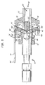
- Fig. 3 shows a cross-sectional view of a preferred embodiment in the unactuated state;
- Fig. 3A shows an end view of a trigger in accordance with an embodiment of the invention;
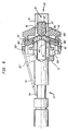
- Fig. 4 shows a cross-sectional view of the Fig. 3 embodiment in the actuated state, without the elastomeric boot;
- Fig. 5 shows a cross-sectional view of an alternate embodiment in the unactuated state, without the elastomeric boot; and
- Fig. 6 shows a cross-sectional view of the Fig. 5 embodiment in the actuated state, without the elastomeric boot.
- In all figures, the same element is always indicated using the same reference numeral. The same or similar parts in the several embodiments are cross-referenced using primed reference numerals. The Figures are not to scale and some dimensions are exaggerated for clarity.
- During most eye surgery, the surgeon makes an incision in the eye and introduces a mechanically operable tool in the incision. Typical tools are forceps, scissors, knives etc.
- In a Sutherland-type instrument system such as is sold in the United States through Grieshaber & Co., Inc. (see Fig. 1),
such tools 2 are detachably securable to the threaded end of ahandle 4. This permits selected ones of a variety of available tools to be threaded onto thehandle 4, used, and removed for cleaning. To operate thetool 2, thehandle 4 is provided with anactuator 6 which takes the form of a pivoted lever having an interior end (not shown, for operating the tool) and an exterior end 8 (for operation by the surgeon's thumb or index finger). When thetool 2 is threaded onto the end of thehandle 4, an interior spring-loaded plunger (not shown) in thetool 2 is urged against the interior end of theactuator 6. When a surgeon depresses theexterior end 8 of theactuator 6 using his index finger or thumb, theactuator 6 pivots. As a result, the interior end presses against the plunger and operates thetool 2 against the pressure of its interior spring (not shown). Such operation can be repeated by repeatedly pressing theexterior end 8 and releasing it. - It is awkward and inconvenient for a surgeon to rotate the tool while maintaining it in its operated position. Either the surgeon must rotate his entire hand and arm while keeping e.g. his index finger depressed, or the surgeon must somehow rearrange his fingers so that at least one finger depresses the
actuator 6 in all rotational positions of the instrument. - Additionally, when the instrument is lying on a work surface and the surgeon wishes to use it, the surgeon must not only rotate the instrument to a position in which the lever is in the proper position but must also rotate the
tool 2 itself so that thetool 2 is properly oriented. By way of example, let it be assumed that thetool 2 is a scissors which is oriented at 12:00 in the instrument tray (not shown). Let it further be assumed that the surgeon wishes to use the scissors at the 3:00 orientation. To do this, the surgeon must pick up the instrument, revolve it in his hand until the instrument is in a comfortable position and then spin thetool 2 to the 3:00 orientation while holding thehandle 4 fixed. - In accordance with the invention as implemented in a pen-type ophthalmic instrument, a pen-type instrument has an elongated handle 4' with an actuator 6' at one end. The actuator 6' has an
actuation surface 10 which extends completely around theaxis 12 of the handle 4'; advantageously, theactuation surface 10 is generally cylindrical and coaxial with theaxis 12 of the handle 4'. Advantageously but not necessarily, theactuation surface 10 is anelastomeric boot 12 which seals the actuator 6' and prevents foreign matter from entering and obstructing the mechanism. The actuator 6' is operated by applying pressure anywhere on theactuation surface 10. Thus, a surgeon who picks up the instrument with the actuator 6' between his thumb and index finger can easily and conveniently rotate the tool whether it is in the operated or unoperated state. Such rotation is easily accomplished by rolling the actuator 6' between the thumb and index finger; operation and release of thetool 2 is easily accomplished by respectively squeezing and releasing the actuator 6'. It is alternatively possible to operate the actuator 6' by holding the handle 4' and pressing theactuation surface 10 of the actuator 6' with the thumb or index finger. - Two embodiments of the invention will now be described. The preferred embodiment of the actuator 6' will be described first with reference to Figs. 3, 3A and 4 and an alternate embodiment of the actuator 6' will be described next with reference to Figs. 5 and 6.
- A central axially
elongated rod 14 supports anose piece 16, which is fixed to theforward end 18 of therod 14. Six triggers 20 (for clarity, only one is shown in Figs. 3 and 4) are pivotally secured to thenose piece 16. Eachtrigger 20 has apivot end 20P, afree end 20F and atie arm 20T; eachtie arm 20T is curved to circulate around therod 14, and eachtie arm 20T has ahook 20H at its distal end (see Fig. 3A). Theboot 12 fits over thenose piece 16 and triggers 20 and is sufficiently elastic to permit thetriggers 20 to move radially inwardly and outwardly. - A
trigger retainer 22 is slidably mounted upon therod 14. Thetrigger retainer 22 is a hollow sleeve which has an annulargrooved region 24 on its radially outer surface. The groovedregion 24 receives thehooks 20H at the ends of the sixtie arms 20T from the six triggers 20; thehook 20H from eachtie arm 20T is disposed within the groovedregion 24. - Each
trigger 20 is pivotally mounted at itspivot end 20P to thenose piece 16. When thefree end 20F of anytrigger 20 is pressed radially inwardly towards therod 14, thehook 20H at the end of thetie arm 20T presses against the groovedregion 24 and urges thetrigger retainer 22 to the right as viewed in Figs. 3 and 4. This causes all thetriggers 20 to simultaneously move radially inwardly. Likewise, when spring pressure urges thetrigger retainer 22 to the left as viewed in Figs. 3 and 4, the free ends 20F of all thetriggers 20 are simultaneously moved radially outwardly, away from therod 14. It may therefore be understood that radially inward and outward motion of any one of thetriggers 20 is converted respectively to rightward and leftward translation of thetrigger retainer 22 and is accompanied by like simultaneous movement of all the other triggers 20. - The
rod 14 has anaxially extending bore 26 which is open at theforward end 28 and which extends rearwardly from theforward end 28. Therod 14 also has an axiallyelongated slot 30 which passes entirely through therod 14 and which intersects thebore 26 near its bottom. Apin 32 is secured to the trigger retainer 22 (as by force-fitting into two diametrically opposed holes) and passes through theslot 30 so as to extend radially with respect to therod 14. - A
slide piston 34 is located within thebore 26. Theslide piston 34 has an enlargedrear end 34R which fits closely within thebore 26 and is located just forwardly of thepin 32. The enlargedrear end 34R of theslide piston 34 insures that theslide piston 34 slides back and forth within thebore 26 and does not become wedged in position as a result of misalignment. Thefront end 34F of theslide piston 34 is cut down and an O-ring 36 (of e.g. Teflon®) is located at thefront end 34F of theslide piston 34. This seals the mechanism and prevents foreign matter (e.g. blood, body fluids etc.) from entering from the openfront end 28 of therod 14. - The operation of the preferred embodiment of the invention will now be explained with simultaneous reference to Figs. 3 and 4. As has been described above, the invention is designed for use with a spring-loaded
tool 2 which is threaded onto the threaded forward end 28 of therod 14. This spring pressure always urges theslide piston 34 to the left as viewed in Figs. 3 and 4. Consequently, when atool 2 has been attached to theforward end 28 of the actuator 6', theslide piston 34 and thepin 32 are always pressed together and a movement of one part will cause all other parts to move as well. - One cycle of operation of the preferred embodiment will now be described. Let it be initially assumed that a
tool 2 has been threaded onto thefront end 28 of the actuator 6'. In this case, spring pressure will move theslide piston 34 to the left as viewed in Figs. 3 and 4. This will push thepin 32 to the left and thetrigger retainer 22 will be pushed to its extreme left position. Thetriggers 20 will then be fully rotated so that theirfree ends 20F are at their radially outermost positions and theelastomeric boot 12 which encloses thetriggers 20 has its maximum diameter. - When a surgeon squeezes the
elastomeric boot 12 between his thumb and index finger, or when a surgeon presses against theboot 12 with e.g. his index finger, force will be applied to at least one of thetriggers 20. This will cause thetrigger retainer 22 to move to the right and will cause all thetriggers 20 to pivot together. This gives the surgeon the tactile sensation that his pressure against the spring loading from thetool 2 causes theboot 12 to collapse smoothly. As thetrigger retainer 22 moves to the right, thepin 32 moves with it. Thepin 32 in turn pushes theslide piston 34, which moves to the right and operates thetool 2 against the pressure exerted by its spring. - When the surgeon wishes to permit the
tool 2 to return to its unoperated position, he relaxes his pressure on theelastomeric boot 12. Spring pressure from thetool 2 then moves theslide piston 34 to the left, pushing thepin 32 and thetrigger retainer 22 to the left and rotating thetriggers 20 so theirfree ends 20F move radially outwardly. - It will be immediately evident that the surgeon can easily and conveniently rotate the preferred embodiment of the invention between his thumb and index finger without changing the state of operation of the
tool 2. It will likewise be immediately evident that the surgeon can operate thetool 2 by pressing at any point on theactuation surface 10. - In the preferred embodiment, the
triggers 20 use elongatedtie arms 20T because this produces substantial translational movement of thetrigger retainer 22 andslide piston 34 with only slight rotation of thetriggers 20. At present, the movement of theslide piston 34 is considered to be sufficient to operate anytool 2 which may be connected to the actuator 6'. However, iffuture tools 2 require more movement, an alternate embodiment exists which amplifies the translational movement of thepiston 32 with respect to the translational movement of thetrigger retainer 22. This alternate embodiment will now be described with reference to Figs. 5 and 6. - In this alternate embodiment, the boot (not shown, but identical to the boot 12) surrounding the actuator 6' conceals from view two sets of mechanical components. The first set is very similar to the structure of the preferred embodiment of the invention; this set of components converts radial motion of the
triggers 20 into linear translation motion within the actuator 6'. In the second set, this translation motion is amplified to provide motion which is adequate to operate any attachedtool 2. The first set will be briefly described first, and the second set will be described next. - A central axially elongated rod 14' (the rod 14' is identical to the
rod 14 in the preferred embodiment) supports a nose piece 16', which is fixed to the forward end 28' of the rod 14'. Six triggers 20' (for clarity, only one is shown in Figs. 5 and 6) are pivotally secured to the nose piece 16'. The triggers 20' are the same as thetriggers 20 in the preferred embodiment, and each trigger 20' has apivot end 20P', afree end 20F' and atie arm 20T'; eachtie arm 20T' is curved to circulate around the rod 14', and eachtie arm 20T' has a 20H' hook at its distal end. The boot (not shown, the same as theboot 12 in the preferred embodiment) fits over the nose piece 16' and triggers 20' and is sufficiently elastic to permit the triggers 20' to move radially inwardly and outwardly. - A trigger retainer 22' is slidably mounted upon the rod 14'. The trigger retainer 22' is similar to, but not the same as, the
trigger retainer 22 in the preferred embodiment. Further as in the preferred embodiment, radial motion of the triggers 20' is converted to longitudinal motion of the trigger retainer 22'; this mechanical action is the same as described in connection with the preferred embodiment. - It is at the front end of the trigger retainer 22' where there are differences with respect to the
trigger retainer 22 in the preferred embodiment. As stated above, the front end of the trigger retainer 22' cooperates with a second set of components which amplifies the motion of the trigger retainer 22' so that the slide piston 34' has a longer stroke than does theslide piston 34 in the preferred embodiment. - The front end of the trigger retainer 22' is formed into a notched
sleeve 22N'. Immediately ahead of the notchedsleeve 22N' are two pins 40'. The radially inner ends of the pins are located within the slot 30', and the rear surfaces of the central regions of the pins 40' are always engaged by the notches of the notchedsleeve 22N'. A slide piston 34' is located within the bore 26' in the rod 14'; the slide piston 34' is identical to theslide piston 34 in the preferred embodiment. - The operation of this second set of components will now be explained with simultaneous reference to Figs. 5 and 6. As has been described above, the invention is designed for use with a spring-loaded
tool 2 which is threaded onto the threaded forward end 28' of the rod 14'. This spring pressure always urges the slide piston 34' to the left as viewed in Figs. 5 and 6. Consequently, when atool 2 has been attached to the forward end 28' of the actuator 6', the piston 34', the pins 40', the notchedslide 22N' and the trigger retainer 22' are always pressed together and a movement of one part will cause all the other parts to move as well. - The radially outer ends 40O' of the pins 40' are cut down to fit into
bores 16B' in the nose piece 16'. This leaves the pins 40' free to pivot but insures that their radially outer ends 40O' are retained at their radial stations with respect to the axis of the rod 14'. Furthermore, the pins 40' fit closely within the slot 30'. The pins 40' are therefore constrained to rotate within a plane about their radially outer endpoints 40O'. As can be seen in Figs. 5 and 6, each of the pins 40' operates as a lever having a fulcrum at its radially outer endpoint 40O', a load adjacent its radially inner endpoint and a force applied by the notchedsleeve 22N' intermediate its endpoints. - The load moved by this type of lever will always move further than the distance over which the force is applied, i.e. this type of lever has a mechanical advantage which is greater than unity. Thus, the notched
sleeve 22N', pins 40' and piston 34' amplify the translational motion of the trigger retainer 22'. In this alternate embodiment, a displacement of 0.060" (approximately 1.5 mm) of the trigger retainer 22' corresponds to a 0.100" (approximately 2.5 mm) displacement of the piston slide 34'. The exact mechanical advantage is determined by the ratio between a) the overall length of the pins 40' and b) the position on the pins 40' where the notchedsleeve 22N' touches the pins 40'. - One cycle of operation of this alternate embodiment will now be described. As before, it is initially assumed that a
tool 2 has been threaded onto the front end 28' of the actuator 6'. In this case, and as is shown in Fig. 5, spring pressure will move the slide piston 34' to the left, the pins 40' will be rotated to their fully unactuated positions, and the notchedslide 22N' and thetrigger retainer 22 will be at their extreme left positions. The triggers 20' will then be fully rotated so that theirfree ends 20F' are at their radially outermost positions and the elastomeric boot (not shown, but identical to the boot 12) which encloses the triggers 20' has its maximum diameter. - When a surgeon squeezes the elastomeric boot between his thumb and index finger, or when a surgeon presses against the boot with e.g. his index finger, force will be applied to at least one of the triggers 20'. This will cause the trigger retainer 22' to move to the right (Fig. 6) and will cause all the triggers 20' to pivot together. As in the preferred embodiment, this gives the surgeon the tactile sensation that his pressure against the spring loading from the
tool 2 causes the boot to collapse smoothly. As the trigger retainer 22' moves to the right, it pushes the notchedsleeve 22N' to the right, which applies force to the middle regions of the pins 40'. As discussed above, the translational motion of thetrigger retainer 22 and the notchedsleeve 22N' is amplified by the pins 40'. Thus, the radially inner ends of the pins 40' move to the right by a distance which exceeds the translational motion of the notchedsleeve 22N', and this amplified motion is transmitted to the slide piston 34', which moves to the right and operates thetool 2 against the pressure exerted by its spring. - When the surgeon wishes to permit the
tool 2 to return to its unoperated position, he relaxes his grip on the elastomeric boot. Spring pressure from thetool 2 then moves the slide piston 34' to the left, pushing the radially inner ends of the pins 40' to the left, moving the notchedslide 22N' and trigger retainer 22' to the left and rotating the triggers 20' so theirfree ends 20F' move radially outwardly. - Now that the basic operation of the preferred embodiment and an alternate embodiment have been described, certain construction details will be discussed.
- Both embodiments described herein utilize handles 4'. This is because such handles are conventional in this type of ophthalmic instrument. However, the use of a handle is not required.
- In the alternate embodiment, each of the pins 40' has an
axially extending bore 40B' extending inwardly from its radially inner end. Acompression spring 40S' of light-gauge wire is supported within thebores 40B' so as to bias the pins 40' in a radially outward direction. The purpose of thisspring 40S' is to insure that the radially inner ends of the pins 40' always move together and to prevent the pins 40' from becoming misaligned within the device. - In both the preferred and alternate embodiments, the
nose piece 16, 16' has the general shape of a cup with an open top and a hole in the center of the bottom. Thenose piece 16, 16' is threaded onto the threadedend 28, 28' of therod 14, 14' and is prevented from sliding rearwardly by an annular stop ridge (not shown) on therod 14, 14'. In the alternate embodiment, the nose piece 16' has two small diametricallyopposed bores 16B' which receive the projections of the pins 40'. This allows the pins 40' to pivot during operation while preventing the radially outer endpoints 40O' of the pins 40' from moving radially outwardly. Outwardly extending tangs on the pivot ends 20P, 20P' of thetriggers 20, 20' engage corresponding notches in thenose piece 16, 16' so that thetriggers 20, 20' can pivot about their pivot ends 20P, 20P'; thetriggers 20, 20' are positively retained in thenose piece 16, 16' by a snap ring (not shown). The elastomeric boot (e.g. 12) slides over the front of thenose piece 16, 16' and covers the circumferential surface of thenose piece 16, 16', the snap ring and thetriggers 20, 20'; the rear end of the boot (e.g. 12) contains an eyelet (e.g. 12E, Fig. 3) and is retained in position on therod 14, 14'. In this way, the entire mechanism is sealed and blood or other body fluids cannot enter into it from the outside to cause corrosion and necessitate cleaning. - While in accordance with the preferred embodiment the
actuation surface 10 is generally cylindrical and coaxial with the handle, 4' this is not necessary. Thesurface 10 may be ribbed or polygonal and may be e.g. studded to provide a better grip. - While in accordance with the preferred embodiment the spring loading is provided by the attached
tool 2, this is only because the preferred embodiment is designed to operate withtools 2 which are already on the market. It would alternatively be possible to provide the spring force using a spring within the handle 4' and to use non-spring-loaded tools. - In the described embodiments, six
triggers 20, 20' are used, but this is not necessary. More orfewer triggers 20, 20' can be used instead. Six triggers 20, 20' are presently preferred because this produces a device which feels circumferentially continuous within theboot 12, but which can still be manufactured at reasonable cost. - In the alternate embodiment, a mechanism is used to amplify the actuation motion of the triggers 20'. This is not necessary; it is alternatively possible if required for the motion amplification mechanism to be replaced by a motion reduction mechanism.
- Although a preferred embodiment has been described above, the scope of the invention is limited only by the following claims:
Claims (16)
- A pen-type instrument for operating a tool, comprising:
an elongated handle; and
an actuator located at an end of the handle, the actuator having an actuation surface which extends completely around the axis of the handle and said actuator being operable by pressure exerted at any point on the actuation surface. - A surgical instrument, comprising:
an operable ophthalmic tool;
an elongated handle; and
an actuator located at an end of the handle and connected in operative relation with the tool, the actuator having an actuation surface which extends completely around the axis of the handle and said actuator being operable by pressure exerted at any point on the actuation surface. - The instrument of claim 2, wherein the tool is detachably secured to the actuator.
- The instrument of claim 2, wherein the actuator has a mechanical advantage which is greater than unity.
- A surgical instrument for operating an ophthalmic tool which is detachably secured thereto, comprising:
an elongated handle;
an actuator located at an end of the handle and having a generally cylindrical actuation surface which is generally coaxial with the handle, the actuator being operable by pressure exerted at any point on the actuation surface; and
means for detachably securing the tool to the actuator in such a manner that when the tool is secured to the actuator, the tool is operated when the actuator is operated by pressure exerted on the actuation surface. - The instrument of claim 5, wherein the actuation surface is a portion of an elastomeric boot.
- The instrument of claim 5, wherein the actuator has a mechanical advantage which is greater than unity.
- The instrument of claim 5, wherein the actuator comprises:
means for converting radial motion of the actuation surface into axial translational motion; and
means for amplifying said translational motion. - The instrument of claim 5, wherein the actuator comprises a plurality of elongated triggers which are regularly spaced around the axis of the handle.
- The instrument of claim 8, wherein said amplifying means comprises a lever.
- The instrument of claim 10, wherein said amplifying means comprises two levers.
- A surgical instrument for operating an ophthalmic tool which is detachably secured thereto, the ophthalmic tool being of the type which is operated by moving a plunger against spring pressure, comprising:
an elongated handle;
an actuator located at an end of the handle and having a generally cylindrical actuation surface which is generally coaxial with the handle, the actuator being operable by pressure exerted at any point on the actuation surface and having a piston which moves axially when the actuator is operated; and
means for detachably securing the tool to the actuator in such a manner that when the tool is secured to the actuator, the plunger and the piston abut each other. - The instrument of claim 12, wherein the actuator comprises:
means for converting radial motion of the actuation surface into axial translational motion. - The instrument of claim 13, wherein the actuator further comprises means for amplifying said translational motion, said amplifying means having a mechanical advantage which is greater than unity.
- An actuator for operating a tool of a type wherein the tool is operated by linear motion along an axis, comprising:
an actuation surface which extends completely around said axis; and
means for producing linear motion along said axis as a result of radially inward motion of said actuation surface. - A surgical instrument, comprising:
an operable tool which is operable by linear motion along an axis; and
an actuator connected in operative relation with the tool, the actuator having an actuation surface which extends completely around said axis and said actuator being operable by pressure exerted at any point on the actuation surface.
Applications Claiming Priority (2)
| Application Number | Priority Date | Filing Date | Title |
|---|---|---|---|
| US328988 | 1994-10-26 | ||
| US08/328,988 US5634918A (en) | 1994-10-26 | 1994-10-26 | Ophthalmic surgical instrument |
Publications (1)
| Publication Number | Publication Date |
|---|---|
| EP0709063A1 true EP0709063A1 (en) | 1996-05-01 |
Family
ID=23283357
Family Applications (1)
| Application Number | Title | Priority Date | Filing Date |
|---|---|---|---|
| EP95116528A Withdrawn EP0709063A1 (en) | 1994-10-26 | 1995-10-20 | Ophthalmic surgical instrument |
Country Status (3)
| Country | Link |
|---|---|
| US (1) | US5634918A (en) |
| EP (1) | EP0709063A1 (en) |
| JP (1) | JPH08206148A (en) |
Cited By (4)
| Publication number | Priority date | Publication date | Assignee | Title |
|---|---|---|---|---|
| CN104596404A (en) * | 2015-01-26 | 2015-05-06 | 哈尔滨飞机工业集团有限责任公司 | Connector hole coaxial error detection tool and method |
| CN109862855A (en) * | 2016-09-27 | 2019-06-07 | 萨诺库里斯有限公司 | Equipment for organizing to remove |
| WO2020157617A1 (en) * | 2019-02-01 | 2020-08-06 | Alcon Inc. | Actuation mechanism with arcuate levers |
| US11583442B2 (en) | 2017-04-09 | 2023-02-21 | Sanoculis Ltd. | Device and method for creating a channel in soft tissue |
Families Citing this family (44)
| Publication number | Priority date | Publication date | Assignee | Title |
|---|---|---|---|---|
| US5741292A (en) * | 1995-10-26 | 1998-04-21 | Eagle Vision | Punctum dilating and plug inserting instrument with push-button plug release |
| US7166117B2 (en) | 1996-02-07 | 2007-01-23 | Hellenkamp Johann F | Automatic surgical device and control assembly for cutting a cornea |
| US5921999A (en) * | 1997-06-03 | 1999-07-13 | Dileo; Frank | System and method employing a pie-zoelectric crystal and transverse oscillation to perform a capsulotomy |
| US5928263A (en) * | 1998-02-02 | 1999-07-27 | Aslan Medical Technologies | Surgical instrument with flexible actuator and rigid actuator cover |
| USD407488S (en) | 1998-06-29 | 1999-03-30 | Alcon Laboratories, Inc. | Surgical handpiece |
| USD421303S (en) * | 1998-09-30 | 2000-02-29 | Becton, Dickinson And Company | Surgical knife handle |
| US6344047B1 (en) | 2000-02-02 | 2002-02-05 | Eagle Vision | Instrument for inserting a punctum plug and method for manufacturing the instrument |
| US6391046B1 (en) | 2000-04-14 | 2002-05-21 | Duke University | Omni-actuatable hand-held surgical instruments |
| US6616683B1 (en) | 2000-05-02 | 2003-09-09 | Duke University | Method of making miniaturized surgical forceps |
| US20030171762A1 (en) * | 2000-08-17 | 2003-09-11 | Forchette Mark J. | Instrument dispenser |
| US6488695B1 (en) | 2000-08-17 | 2002-12-03 | Alcon, Inc. | Ophthalmologic surgical probe |
| US6482198B2 (en) * | 2001-04-19 | 2002-11-19 | Duke University | Hand-held surgical instruments with omni-circumferential actuation capabilities |
| US20060089661A1 (en) | 2002-05-06 | 2006-04-27 | Dodge Brian C | Omni-actuable hand-held surgical instruments |
| USD497427S1 (en) | 2002-12-19 | 2004-10-19 | Alcon, Inc. | Microsurgical instrument |
| CN100486549C (en) | 2003-04-07 | 2009-05-13 | 泰克诺拉斯眼科系统有限公司 | Connecting rod driving system of microkeratome |
| USD491268S1 (en) | 2003-04-10 | 2004-06-08 | Alcon, Inc. | Microsurgical instrument |
| US20050085798A1 (en) * | 2003-09-15 | 2005-04-21 | Hofmann Ronald L. | Adjustable surgical cutting instrument and cam system for use in same |
| JP2007514465A (en) | 2003-11-13 | 2007-06-07 | シナージエテイクス・インコーポレイテツド | Surgical device handle with adjustable actuator position |
| CN101198301A (en) * | 2005-05-18 | 2008-06-11 | 苏尔莫迪克斯公司 | Insertion instruments for non-linear medical devices |
| US7766937B2 (en) * | 2006-03-13 | 2010-08-03 | Mini-Lap Technologies, Inc. | Minimally invasive surgical assembly and methods |
| US8313507B2 (en) * | 2006-03-13 | 2012-11-20 | Mini-Lap Technologies, Inc. | Minimally invasive rake retractor and method for using same |
| US9486238B2 (en) * | 2006-03-13 | 2016-11-08 | Teleflex Medical Incorporated | Minimally invasive surgical clamps, assemblies and methods |
| WO2007106813A2 (en) * | 2006-03-13 | 2007-09-20 | Minilap Technologies, Inc. | Minimally invasive surgical assembly and methods |
| US8133255B2 (en) * | 2006-03-13 | 2012-03-13 | Mini-Lap Technologies, Inc. | Minimally invasive surgical assembly and methods |
| US20070282170A1 (en) * | 2006-05-30 | 2007-12-06 | Sundaram Ravikumar | Rake Retractor and Needle Assembly for Minimally Invasive Surgical Applications |
| US20080086166A1 (en) * | 2006-10-10 | 2008-04-10 | Sundaram Ravikumar | Minimally Invasive Surgical Assembly with Balloon Instrument |
| US8956351B2 (en) * | 2008-04-09 | 2015-02-17 | Teleflex Medical Incorporated | Minimally invasive surgical needle and cauterizing assembly and methods |
| USD629111S1 (en) * | 2009-03-23 | 2010-12-14 | Karl Storz Gmbh & Co. Kg | Blood analysis instrument |
| US20110166555A1 (en) * | 2009-09-30 | 2011-07-07 | Jianbo Zhou | Carrier for an insertable medical device, insertion tools, methods of use, and kits |
| US9326757B2 (en) * | 2009-12-31 | 2016-05-03 | Teleflex Medical Incorporated | Surgical instruments for laparoscopic aspiration and retraction |
| US8579887B2 (en) | 2010-11-09 | 2013-11-12 | Synergetics Usa, Inc. | Axially reciprocating microsurgical instrument with radially compressed actuator handle |
| WO2012082751A1 (en) * | 2010-12-13 | 2012-06-21 | I-Tech Development Company | Distally actuated surgical instrument |
| WO2012082736A1 (en) * | 2010-12-13 | 2012-06-21 | I-Tech Development Company | Proximally actuated surgical instrument |
| US9161769B2 (en) | 2012-07-30 | 2015-10-20 | Covidien Lp | Endoscopic instrument |
| US9320534B2 (en) | 2012-12-13 | 2016-04-26 | Alcon Research, Ltd. | Fine membrane forceps with integral scraping feature |
| US10973682B2 (en) | 2014-02-24 | 2021-04-13 | Alcon Inc. | Surgical instrument with adhesion optimized edge condition |
| USD762302S1 (en) | 2014-04-24 | 2016-07-26 | University Of Massachusetts | Surgical forceps |
| US10201362B2 (en) | 2014-04-24 | 2019-02-12 | University Of Massachusetts | Contoured surgical forceps |
| ITUB20154977A1 (en) | 2015-10-16 | 2017-04-16 | Medical Microinstruments S R L | Medical instrument and method of manufacture of said medical instrument |
| TW201815356A (en) | 2016-10-18 | 2018-05-01 | 諾華公司 | Surgical instrument with surface texture |
| CN110099608B (en) | 2016-11-23 | 2022-07-29 | 巴德股份有限公司 | Single insertion multiple sample biopsy device |
| JP7258025B2 (en) | 2017-11-30 | 2023-04-14 | シー・アール・バード・インコーポレーテッド | Specimen container and coaxial introducer cannula for biopsy device |
| WO2019220407A1 (en) | 2018-05-17 | 2019-11-21 | Medical Microinstruments S.p.A. | Master controller assembly for a robotic surgery system, particularly for microsurgery |
| IT201800005468A1 (en) | 2018-05-17 | 2019-11-17 | Robotic system for surgery, particularly microsurgery |
Citations (4)
| Publication number | Priority date | Publication date | Assignee | Title |
|---|---|---|---|---|
| US4258716A (en) * | 1978-02-06 | 1981-03-31 | The University Of Melbourne | Microsurgical instruments |
| DE3526821A1 (en) * | 1985-07-26 | 1987-02-05 | Ewald Hensler | Gripping piece with an actuation device for a manually operated, surgical microinstrument |
| DE4211417A1 (en) * | 1992-04-04 | 1993-10-07 | Rema Medizintechnik Gmbh | Surgical endo-instrument for use with endoscope - has jaws at outer end of tubular body which are actuated by mechanism inside hollow handle |
| US5355871A (en) * | 1992-09-11 | 1994-10-18 | Dexide, Inc. | Elastomeric controller for endoscopic surgical instruments |
Family Cites Families (8)
| Publication number | Priority date | Publication date | Assignee | Title |
|---|---|---|---|---|
| US3133526A (en) * | 1960-12-19 | 1964-05-19 | Hartley Pen Co | Writing instrument with largecapacity cartridge |
| US3576374A (en) * | 1969-03-10 | 1971-04-27 | Leila J Lile | Pencil operating mechanism |
| US5133727A (en) * | 1990-05-10 | 1992-07-28 | Symbiosis Corporation | Radial jaw biopsy forceps |
| US4655219A (en) * | 1983-07-22 | 1987-04-07 | American Hospital Supply Corporation | Multicomponent flexible grasping device |
| US5082000A (en) * | 1990-11-29 | 1992-01-21 | Applied Medical Technology, Inc. | Biopsy forceps with calde controlled jaws |
| US5224954A (en) * | 1991-02-19 | 1993-07-06 | Dexide, Inc. | Combination surgical trocar cannula and rake assembly |
| US5211652A (en) * | 1991-10-03 | 1993-05-18 | Bruce Derbyshire | Scalpel |
| US5222973A (en) * | 1992-03-09 | 1993-06-29 | Sharpe Endosurgical Corporation | Endoscopic grasping tool surgical instrument |
-
1994
- 1994-10-26 US US08/328,988 patent/US5634918A/en not_active Expired - Lifetime
-
1995
- 1995-10-20 EP EP95116528A patent/EP0709063A1/en not_active Withdrawn
- 1995-10-26 JP JP7279102A patent/JPH08206148A/en not_active Withdrawn
Patent Citations (4)
| Publication number | Priority date | Publication date | Assignee | Title |
|---|---|---|---|---|
| US4258716A (en) * | 1978-02-06 | 1981-03-31 | The University Of Melbourne | Microsurgical instruments |
| DE3526821A1 (en) * | 1985-07-26 | 1987-02-05 | Ewald Hensler | Gripping piece with an actuation device for a manually operated, surgical microinstrument |
| DE4211417A1 (en) * | 1992-04-04 | 1993-10-07 | Rema Medizintechnik Gmbh | Surgical endo-instrument for use with endoscope - has jaws at outer end of tubular body which are actuated by mechanism inside hollow handle |
| US5355871A (en) * | 1992-09-11 | 1994-10-18 | Dexide, Inc. | Elastomeric controller for endoscopic surgical instruments |
Cited By (10)
| Publication number | Priority date | Publication date | Assignee | Title |
|---|---|---|---|---|
| CN104596404A (en) * | 2015-01-26 | 2015-05-06 | 哈尔滨飞机工业集团有限责任公司 | Connector hole coaxial error detection tool and method |
| CN109862855A (en) * | 2016-09-27 | 2019-06-07 | 萨诺库里斯有限公司 | Equipment for organizing to remove |
| US11471325B2 (en) | 2016-09-27 | 2022-10-18 | Sanoculis Ltd. | Apparatus for tissue removal |
| CN109862855B (en) * | 2016-09-27 | 2023-10-27 | 萨诺库里斯有限公司 | Equipment used to organize removal |
| US12336935B2 (en) | 2016-09-27 | 2025-06-24 | Sanoculis Ltd | Apparatus for tissue removal |
| US11583442B2 (en) | 2017-04-09 | 2023-02-21 | Sanoculis Ltd. | Device and method for creating a channel in soft tissue |
| US11701257B2 (en) | 2017-04-09 | 2023-07-18 | Sanoculis Ltd. | Device and method for creating a channel in soft tissue |
| US11974947B2 (en) | 2017-04-09 | 2024-05-07 | Sanoculis Ltd. | Device and method for creating a channel in soft tissue |
| WO2020157617A1 (en) * | 2019-02-01 | 2020-08-06 | Alcon Inc. | Actuation mechanism with arcuate levers |
| US11298146B2 (en) | 2019-02-01 | 2022-04-12 | Alcon Inc. | Actuation mechanism with arcuate levers |
Also Published As
| Publication number | Publication date |
|---|---|
| US5634918A (en) | 1997-06-03 |
| JPH08206148A (en) | 1996-08-13 |
Similar Documents
| Publication | Publication Date | Title |
|---|---|---|
| US5634918A (en) | Ophthalmic surgical instrument | |
| US7004957B1 (en) | Actuating and locking mechanism for a surgical tool | |
| US5713505A (en) | Articulation transmission mechanism for surgical instruments | |
| US6540737B2 (en) | Handle for a medical instrument | |
| US4273129A (en) | Forceps for applying clips to fallopian tubes | |
| US6287251B1 (en) | Speculum | |
| US6391046B1 (en) | Omni-actuatable hand-held surgical instruments | |
| US20040064067A1 (en) | Fluid pressure-actuated medical device | |
| US6482198B2 (en) | Hand-held surgical instruments with omni-circumferential actuation capabilities | |
| WO2001067965A1 (en) | Applicator for surgical clips | |
| US5707377A (en) | Ligation clip remover | |
| US6299624B1 (en) | Handle for a medical instrument | |
| US20060089661A1 (en) | Omni-actuable hand-held surgical instruments | |
| WO1996002193A1 (en) | Track guided end effector assembly | |
| US20070260277A1 (en) | Tubular shaft instrument | |
| GB2027633A (en) | Forceps for applying clips to fallopian tubes |
Legal Events
| Date | Code | Title | Description |
|---|---|---|---|
| PUAI | Public reference made under article 153(3) epc to a published international application that has entered the european phase |
Free format text: ORIGINAL CODE: 0009012 |
|
| AK | Designated contracting states |
Kind code of ref document: A1 Designated state(s): AT CH DE ES FR GB IT LI NL SE |
|
| STAA | Information on the status of an ep patent application or granted ep patent |
Free format text: STATUS: THE APPLICATION IS DEEMED TO BE WITHDRAWN |
|
| 18D | Application deemed to be withdrawn |
Effective date: 19961102 |