EP0522487A1 - Process and device for controlling the thickness profile during manufacture of blown films - Google Patents
Process and device for controlling the thickness profile during manufacture of blown films Download PDFInfo
- Publication number
- EP0522487A1 EP0522487A1 EP92111438A EP92111438A EP0522487A1 EP 0522487 A1 EP0522487 A1 EP 0522487A1 EP 92111438 A EP92111438 A EP 92111438A EP 92111438 A EP92111438 A EP 92111438A EP 0522487 A1 EP0522487 A1 EP 0522487A1
- Authority
- EP
- European Patent Office
- Prior art keywords
- cooling air
- actuators
- control
- cooling
- individual
- Prior art date
- Legal status (The legal status is an assumption and is not a legal conclusion. Google has not performed a legal analysis and makes no representation as to the accuracy of the status listed.)
- Granted
Links
- 238000000034 method Methods 0.000 title claims abstract description 11
- 238000004519 manufacturing process Methods 0.000 title claims abstract description 4
- 230000008569 process Effects 0.000 title abstract description 4
- 238000001816 cooling Methods 0.000 claims abstract description 81
- 230000001105 regulatory effect Effects 0.000 claims abstract description 8
- 230000001276 controlling effect Effects 0.000 claims abstract description 4
- 230000002093 peripheral effect Effects 0.000 claims description 5
- 230000033228 biological regulation Effects 0.000 description 5
- 230000008859 change Effects 0.000 description 5
- 230000006870 function Effects 0.000 description 3
- 230000003993 interaction Effects 0.000 description 3
- 238000013178 mathematical model Methods 0.000 description 3
- 238000005192 partition Methods 0.000 description 3
- 238000004364 calculation method Methods 0.000 description 2
- 238000012937 correction Methods 0.000 description 2
- 238000011144 upstream manufacturing Methods 0.000 description 2
- 230000006835 compression Effects 0.000 description 1
- 238000007906 compression Methods 0.000 description 1
- 230000008878 coupling Effects 0.000 description 1
- 238000010168 coupling process Methods 0.000 description 1
- 238000005859 coupling reaction Methods 0.000 description 1
- 230000001419 dependent effect Effects 0.000 description 1
- 238000010586 diagram Methods 0.000 description 1
- 230000000694 effects Effects 0.000 description 1
- 238000013213 extrapolation Methods 0.000 description 1
- 239000011159 matrix material Substances 0.000 description 1
- 230000001404 mediated effect Effects 0.000 description 1
- 230000009466 transformation Effects 0.000 description 1
Images


Classifications
-
- B—PERFORMING OPERATIONS; TRANSPORTING
- B29—WORKING OF PLASTICS; WORKING OF SUBSTANCES IN A PLASTIC STATE IN GENERAL
- B29C—SHAPING OR JOINING OF PLASTICS; SHAPING OF MATERIAL IN A PLASTIC STATE, NOT OTHERWISE PROVIDED FOR; AFTER-TREATMENT OF THE SHAPED PRODUCTS, e.g. REPAIRING
- B29C48/00—Extrusion moulding, i.e. expressing the moulding material through a die or nozzle which imparts the desired form; Apparatus therefor
- B29C48/25—Component parts, details or accessories; Auxiliary operations
- B29C48/88—Thermal treatment of the stream of extruded material, e.g. cooling
- B29C48/885—External treatment, e.g. by using air rings for cooling tubular films
-
- B—PERFORMING OPERATIONS; TRANSPORTING
- B29—WORKING OF PLASTICS; WORKING OF SUBSTANCES IN A PLASTIC STATE IN GENERAL
- B29C—SHAPING OR JOINING OF PLASTICS; SHAPING OF MATERIAL IN A PLASTIC STATE, NOT OTHERWISE PROVIDED FOR; AFTER-TREATMENT OF THE SHAPED PRODUCTS, e.g. REPAIRING
- B29C48/00—Extrusion moulding, i.e. expressing the moulding material through a die or nozzle which imparts the desired form; Apparatus therefor
- B29C48/03—Extrusion moulding, i.e. expressing the moulding material through a die or nozzle which imparts the desired form; Apparatus therefor characterised by the shape of the extruded material at extrusion
- B29C48/09—Articles with cross-sections having partially or fully enclosed cavities, e.g. pipes or channels
- B29C48/10—Articles with cross-sections having partially or fully enclosed cavities, e.g. pipes or channels flexible, e.g. blown foils
-
- B—PERFORMING OPERATIONS; TRANSPORTING
- B29—WORKING OF PLASTICS; WORKING OF SUBSTANCES IN A PLASTIC STATE IN GENERAL
- B29C—SHAPING OR JOINING OF PLASTICS; SHAPING OF MATERIAL IN A PLASTIC STATE, NOT OTHERWISE PROVIDED FOR; AFTER-TREATMENT OF THE SHAPED PRODUCTS, e.g. REPAIRING
- B29C48/00—Extrusion moulding, i.e. expressing the moulding material through a die or nozzle which imparts the desired form; Apparatus therefor
- B29C48/25—Component parts, details or accessories; Auxiliary operations
- B29C48/88—Thermal treatment of the stream of extruded material, e.g. cooling
- B29C48/911—Cooling
- B29C48/9115—Cooling of hollow articles
- B29C48/912—Cooling of hollow articles of tubular films
-
- B—PERFORMING OPERATIONS; TRANSPORTING
- B29—WORKING OF PLASTICS; WORKING OF SUBSTANCES IN A PLASTIC STATE IN GENERAL
- B29C—SHAPING OR JOINING OF PLASTICS; SHAPING OF MATERIAL IN A PLASTIC STATE, NOT OTHERWISE PROVIDED FOR; AFTER-TREATMENT OF THE SHAPED PRODUCTS, e.g. REPAIRING
- B29C48/00—Extrusion moulding, i.e. expressing the moulding material through a die or nozzle which imparts the desired form; Apparatus therefor
- B29C48/25—Component parts, details or accessories; Auxiliary operations
- B29C48/92—Measuring, controlling or regulating
-
- B—PERFORMING OPERATIONS; TRANSPORTING
- B29—WORKING OF PLASTICS; WORKING OF SUBSTANCES IN A PLASTIC STATE IN GENERAL
- B29C—SHAPING OR JOINING OF PLASTICS; SHAPING OF MATERIAL IN A PLASTIC STATE, NOT OTHERWISE PROVIDED FOR; AFTER-TREATMENT OF THE SHAPED PRODUCTS, e.g. REPAIRING
- B29C2948/00—Indexing scheme relating to extrusion moulding
- B29C2948/92—Measuring, controlling or regulating
- B29C2948/92504—Controlled parameter
- B29C2948/9258—Velocity
- B29C2948/926—Flow or feed rate
-
- B—PERFORMING OPERATIONS; TRANSPORTING
- B29—WORKING OF PLASTICS; WORKING OF SUBSTANCES IN A PLASTIC STATE IN GENERAL
- B29C—SHAPING OR JOINING OF PLASTICS; SHAPING OF MATERIAL IN A PLASTIC STATE, NOT OTHERWISE PROVIDED FOR; AFTER-TREATMENT OF THE SHAPED PRODUCTS, e.g. REPAIRING
- B29C2948/00—Indexing scheme relating to extrusion moulding
- B29C2948/92—Measuring, controlling or regulating
- B29C2948/92504—Controlled parameter
- B29C2948/92609—Dimensions
- B29C2948/92647—Thickness
-
- B—PERFORMING OPERATIONS; TRANSPORTING
- B29—WORKING OF PLASTICS; WORKING OF SUBSTANCES IN A PLASTIC STATE IN GENERAL
- B29C—SHAPING OR JOINING OF PLASTICS; SHAPING OF MATERIAL IN A PLASTIC STATE, NOT OTHERWISE PROVIDED FOR; AFTER-TREATMENT OF THE SHAPED PRODUCTS, e.g. REPAIRING
- B29C2948/00—Indexing scheme relating to extrusion moulding
- B29C2948/92—Measuring, controlling or regulating
- B29C2948/92504—Controlled parameter
- B29C2948/92704—Temperature
-
- B—PERFORMING OPERATIONS; TRANSPORTING
- B29—WORKING OF PLASTICS; WORKING OF SUBSTANCES IN A PLASTIC STATE IN GENERAL
- B29C—SHAPING OR JOINING OF PLASTICS; SHAPING OF MATERIAL IN A PLASTIC STATE, NOT OTHERWISE PROVIDED FOR; AFTER-TREATMENT OF THE SHAPED PRODUCTS, e.g. REPAIRING
- B29C2948/00—Indexing scheme relating to extrusion moulding
- B29C2948/92—Measuring, controlling or regulating
- B29C2948/92819—Location or phase of control
- B29C2948/92923—Calibration, after-treatment or cooling zone
-
- B—PERFORMING OPERATIONS; TRANSPORTING
- B29—WORKING OF PLASTICS; WORKING OF SUBSTANCES IN A PLASTIC STATE IN GENERAL
- B29C—SHAPING OR JOINING OF PLASTICS; SHAPING OF MATERIAL IN A PLASTIC STATE, NOT OTHERWISE PROVIDED FOR; AFTER-TREATMENT OF THE SHAPED PRODUCTS, e.g. REPAIRING
- B29C48/00—Extrusion moulding, i.e. expressing the moulding material through a die or nozzle which imparts the desired form; Apparatus therefor
- B29C48/03—Extrusion moulding, i.e. expressing the moulding material through a die or nozzle which imparts the desired form; Apparatus therefor characterised by the shape of the extruded material at extrusion
Definitions
- the invention relates to a method for controlling the transverse profile in the production of blown film, in which cooling air is supplied to the circumference of the film bubble with the aid of a cooling ring which allows a cooling air supply in segments with the aid of separate actuators in the individual peripheral regions of the film bubble.
- the invention further relates to a device for performing this method.
- the film thickness is influenced in that the cooling capacity is varied on the circumference of the pollen bladder. If the cooling capacity is increased in a certain circumferential segment, the film cools down faster there, so that it is not stretched as much and is given a correspondingly greater thickness. Conversely, the film thickness can be reduced by reducing the cooling capacity.
- DE-PS 26 58 518 describes a device in which a ring of additional nozzles is attached above the outer cooling ring, which are fed by a common ring line and whose throughput is individually adjustable with the aid of throttles.
- the cooling air flow is influenced by interference pins projecting more or less far into the interior of the cooling ring, so that the flow resistance of the cooling ring can be varied in segments.
- a cooling ring is known from DE-OS 37 43 720, in which radial partition walls adjoin a circumferential barrage to even out the cooling air flow and divide the cooling ring into individual segments. In each segment there is a stamp which can be adjusted either in height or in the radial direction and with which the flow resistance can be changed.
- a measuring device is provided on the film bubble above the cooling ring, with which the thickness profile of the film is measured and reported back to a control device as a feedback signal, so that the film thickness can be controlled in a closed control loop using the actuators on the cooling ring.
- this regulation proves to be extremely difficult.
- a major disadvantage of the conventional systems is that there is a change in the flow resistance and thus a change in the pressure and flow conditions during an actuating operation on a single actuator comes upstream of the actuators in the ring line, which has repercussions on the neighboring actuators. Due to these interactions between the individual segments, the cooling system as a whole is difficult to control.
- the invention has for its object to show alternative ways to compensate for the interactions between the actuating operations on the individual segments in the control or regulation of the cross profile.
- a separate control circuit is assigned to each actuator.
- the overall control or regulating device does not directly supply the control commands for the actuators, but only setpoints that serve as reference variables for the lower-level control loops of the individual actuators. Since the lower-level control loops respond very quickly to faults or changes in the setpoint values due to the comparatively short control path, it can be ensured that the throughput in each individual cooling ring segment corresponds precisely to the setpoint value set in each case. In principle, when the throughput in one segment changes, there are repercussions on the neighboring segments, but these are immediately compensated for by the control loops of the neighboring segments.
- the adjustment processes in the individual segments are so short that they do not have a noticeable effect on the film thickness in view of the relatively high viscosity and inertia of the film bubble. In this way, precise control or regulation of the transverse profile of the film is made possible.
- the actuators and the associated control loops are formed by pneumatic proportional valves which are acted upon by the output pressure downstream of the valve as a feedback signal and thus supply an output pressure proportional to the respectively set target value, regardless of the input pressure.
- the actuators are designed as electrically controllable valves which are controlled by an associated controller as a function of the feedback signal from a pressure sensor arranged downstream of the valve in the cooling ring.
- a memory device in which an associated set of control commands for the control elements is stored in a multi-dimensional map for each set of target values. If a change in the setpoint for an individual segment is required as part of the control or regulation of the cross profile, not only is the control command for the relevant segment changed, but the new setpoint combination is sought in the map and the control commands for all segments are taken into account the total of the setpoints reset according to the data stored in the map.
- the stored data are empirically determined in advance for the cooling ring in question. One can proceed in such a way that a finite number of control commands is specified for each actuator and then all possible combinations of control commands are run through in succession.
- the pressures or flow velocities downstream of the actuators which are representative of the cooling air flow rates in the individual segments, are measured and stored for each combination of actuating commands.
- the associated set of control commands can then be determined in the opposite direction on the basis of the stored measured values which correspond to the current setpoints. Intermediate values or values outside the map can be determined by interpolation or extrapolation.
- the device according to claim 5 thus makes it possible to take into account the interdependencies between the individual segments of the cooling ring from the outset when determining the actuating commands. Since only previously stored values have to be called up for this purpose, a sufficiently high processing speed can be achieved with the aid of relatively simple and inexpensive hardware.
- a computer with a sufficiently high computing power is provided instead of the memory device, which calculates the associated set of control commands from the respective set of target values in real time in accordance with a previously empirically determined calculation rule.
- the calculation rule represents a mathematical model that reflects the aerodynamic properties of the cooling ring.
- nonlinear models are also conceivable, as are dynamic models in which, in addition to the target values, the changes in the target values are also taken into account, so that the change in the flow pattern in the cooling ring over time can also be appropriately modeled when the target values change.
- cooling ring segments into aerodynamically separate groups, each of which is fed by separate funding, so that mutual interactions only occur between the relatively few segments of the same group.
- a film bubble 10 is extruded from a tool 12.
- a cooling ring 14 surrounding the film bubble is mounted on the tool 12.
- the cooling ring 14 has in its outer circumferential area a circumferential annular chamber 16 which is connected to a cooling air blower, not shown connected.
- a radial stage 18 adjoins the annular chamber 16, through which a uniform circumferential distribution of the cooling air flow is achieved.
- Behind the barrage 18, the interior of the cooling ring is divided into individual segments 22 by radial partition walls 20.
- the partition walls 20 extend to the outlet gap 24 on the inner peripheral edge of the cooling ring.
- a controllable proportional valve 26 is assigned to each segment 22 of the cooling ring, with which the pressure in the segment 22 and thus the cooling air throughput through the outlet gap 24 in the segment in question is regulated to a predetermined desired value.
- the proportional valve 26 has a valve member 28 which is provided at its lower end with a piston 30 with a larger diameter and at the upper end with a stem 32 with a smaller diameter.
- the shaft 32 runs in a pressure-tight manner through the upper wall of the cooling ring 14 and is supported on a tappet 36 of an electrically controllable drive member 38 via a helical compression spring 34.
- the bottom of the piston 30 is pressurized in the segment 22, while the top of the piston is pressurized via a channel 40 with atmospheric pressure. Due to the pressure difference between the pressure in the segment 22 and the atmospheric pressure, the piston 30 is pressed upward against the force of the spring 34, so that the valve member 28 projects into the flow path for the cooling air and thus throttles the air throughput through this flow path.
- This throttling of the air supply leads to a decrease in the pressure in the segment 22 downstream of the valve member 28 and thus to a decrease in the pressure drop on the piston 30. In this way, an equilibrium is finally established at a pressure dependent on the spring force of the spring 34.
- the drive member 38 receives a setpoint signal from a control device, not shown, which serves to control the thickness profile of the film bubble 10 in the circumferential direction as a function of the thickness profile measured further above on the film bubble.
- the position of the plunger 36 is set by the drive member 38 in accordance with the setpoint signal.
- the spring force of the spring 34 and thus the pressure in the segment 22 and finally the cooling air throughput through the outlet gap 24 are set in accordance with the desired value.
- pressure fluctuations occur in the ring line 16 upstream of the proportional valve 26 there is a temporary drop in the Pressure in the segment 22 below the setpoint. However, this pressure deviation is compensated for by the piston 30 with an extremely short control delay.
- the cooling air throughput in each individual segment of the cooling ring 14 is regulated to the desired value transmitted to the associated proportional valve 26.
- the device described above can be used advantageously in cases in which there is no regulation, but rather control of the transverse profile of the film bubble 10.
- the upper surface of the valve member 28 is significantly smaller than the effective area of the piston 30, so that the influence of the pressure on the surface of the valve member is negligible.
- the valve member can also be designed as a plate-shaped locking slide.
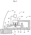
- the exemplary embodiment shown in FIG. 2 differs from the previously described embodiment in that, instead of the proportional valve 26, a control circuit 42 is provided, which has an electrically actuable throttle valve 44, a pressure sensor 46 arranged downstream of the throttle valve in the segment 22, and one via a feedback line 48 contains controller 50 connected to the pressure sensor.
- the throttle valve 44 has a drive member 52 with which the position of the valve member 54 can be set as a function of a signal from the controller 50.
- the pressure in the segment 52 influenced by the position of the valve member 54 is detected by the pressure sensor 46 and reported back to the controller 50 and is thus regulated to the setpoint value which is transmitted to the controller 50 by the cross-profile regulating or control device, not shown .
- FIG. 3 shows another embodiment of a device for regulating the cross profile.
- a measuring head 56 running around the circumference of the film bubble serves to receive the transverse profile of the film and delivers a corresponding measuring signal to a transverse profile controller 58.
- the cooling ring is divided into segments, each of which is assigned an actuator 60.
- the actuators 16 can, for example, be designed and arranged like the throttle valves 44 according to FIG. 2.
- the segments of the cooling ring are combined into groups, each of which is supplied with cooling air by a separate fan. In Figure 3, only four actuators 60 of a group consisting of four segments are shown as an example.
- the cross profile controller 58 generates a setpoint signal for each of the actuators 60, which indicates the setpoint for the cooling air throughput in the relevant segment and is determined by the cross profile controller 58 so that the desired thickness profile of the film bubble results.
- the setpoint signals are transmitted to a computer 62, which retrieves a set of four control commands belonging to the four setpoint signals from a memory 64 and outputs them to the actuators 60.
- a mathematical model of the cooling ring can also be stored in the memory 64, on the basis of which the computer 62 calculates the control commands from the target values.
Landscapes
- Engineering & Computer Science (AREA)
- Mechanical Engineering (AREA)
- Physics & Mathematics (AREA)
- Thermal Sciences (AREA)
- Extrusion Moulding Of Plastics Or The Like (AREA)
- Shaping By String And By Release Of Stress In Plastics And The Like (AREA)
Abstract
Description
Die Erfindung betrifft ein Verfahren zur Steuerung des Querprofils bei der Blasfolienherstellung, bei dem Kühlluft am Umfang der Folienblase mit Hilfe eines Kühlringes zugeführt wird, der eine segmentweise Kühlluftzufuhr mit Hilfe von gesonderten Stellgliedern in den einzelnen Umfangsbereichen der Folienblase gestattet. Ferner betrifft die Erfindung eine Vorrichtung zur Durchführung dieses Verfahrens.The invention relates to a method for controlling the transverse profile in the production of blown film, in which cooling air is supplied to the circumference of the film bubble with the aid of a cooling ring which allows a cooling air supply in segments with the aid of separate actuators in the individual peripheral regions of the film bubble. The invention further relates to a device for performing this method.
Bei Verfahren und Vorrichtungen dieser Art wird die Foliendicke dadurch beeinflußt, daß die Kühlleistung am Umfang der Follenblase variiert wird. Bei einer Erhöhung der Kühlleistung in einem bestimmten Umfangssegment kühlt sich die Folie dort schneller ab, so daß sie nicht so stark gedehnt wird und eine entsprechend größere Dicke erhält. Umgekehrt kann durch eine Verringerung der Kühlleistung die Foliendicke vermindert werden.In processes and devices of this type, the film thickness is influenced in that the cooling capacity is varied on the circumference of the pollen bladder. If the cooling capacity is increased in a certain circumferential segment, the film cools down faster there, so that it is not stretched as much and is given a correspondingly greater thickness. Conversely, the film thickness can be reduced by reducing the cooling capacity.
In der DE-PS 26 58 518 wird eine Vorrichtung beschrieben, bei der oberhalb des Außen-Kühlrings ein Kranz von zusätzlichen Düsen angebracht ist, die durch eine gemeinsame Ringleitung gespeist werden und deren Durchsatz individuell mit Hilfe von Drosseln verstellbar ist. Gemäß der DE-OS 36 27 129 wird die Kühlluftströmung durch mehr oder weniger weit in das Innere des Kühlrings ragende Störstifte beeinflußt, so daß der Strömungswiderstand des Kühlrings segmentweise variiert werden kann. Aus der DE-OS 37 43 720 ist ein Kühlring bekannt, bei dem sich an eine umlaufende Staustufe zur Vergleichmäßigung der Kühlluftströmung nach innen radiale Trennwände anschließen, die den Kühlring in einzelne Segmente unterteilen. In jedem Segment ist ein entweder in der Höhe oder in Radialrichtung verstellbarer Stempel angeordnet, mit dem sich der Strömungswiderstand verändern läßt.DE-PS 26 58 518 describes a device in which a ring of additional nozzles is attached above the outer cooling ring, which are fed by a common ring line and whose throughput is individually adjustable with the aid of throttles. According to DE-OS 36 27 129, the cooling air flow is influenced by interference pins projecting more or less far into the interior of the cooling ring, so that the flow resistance of the cooling ring can be varied in segments. A cooling ring is known from DE-OS 37 43 720, in which radial partition walls adjoin a circumferential barrage to even out the cooling air flow and divide the cooling ring into individual segments. In each segment there is a stamp which can be adjusted either in height or in the radial direction and with which the flow resistance can be changed.
In einigen Fällen ist an der Folienblase oberhalb des Kühlrings eine Meßeinrichtung vorgesehen, mit der das Dickenprofil der Folie gemessen und als Rückkopplungssignal an eine Regeleinrichtung zurückgemeldet wird, so daß die Foliendicke mit Hilfe der Stellglieder am Kühlring in einem geschlossenen Regelkreis geregelt werden kann. In der Praxis erweist sich diese Regelung jedoch als äußerst schwierig.In some cases, a measuring device is provided on the film bubble above the cooling ring, with which the thickness profile of the film is measured and reported back to a control device as a feedback signal, so that the film thickness can be controlled in a closed control loop using the actuators on the cooling ring. In practice, however, this regulation proves to be extremely difficult.
Ein wesentlicher Nachteil der herkömmlichen Systeme besteht darin, daß es bei einer Stelloperation an einem einzelnen Stellglied zu einer Änderung des Strömungswiderstandes und damit zu einer Änderung der Druck- und Strömungsverhältnisse in der Ringleitung stromaufwärts der Stellglieder kommt, wodurch sich Rückwirkungen auf die benachbarten Stellglieder ergeben. Aufgrund dieser Wechselwirkungen zwischen den einzelnen Segmenten ist das Kühlsystem insgesamt nur schwer zu beherrschen.A major disadvantage of the conventional systems is that there is a change in the flow resistance and thus a change in the pressure and flow conditions during an actuating operation on a single actuator comes upstream of the actuators in the ring line, which has repercussions on the neighboring actuators. Due to these interactions between the individual segments, the cooling system as a whole is difficult to control.
In WO 90/15707 ist deshalb eine aerodynamische Entkopplung der einzelnen Kühlringsegmente vorgeschlagen worden. Dies wird beispielsweise durch getrennte Fördermittel für jedes einzelne Kühlringsegment erreicht, oder durch Stellglieder, mit denen ein mehr oder weniger großer Anteil der Kühlluft ohne Änderung des Gesamt-Strömungswiderstandes in dem Segment so umgelenkt wird, daß er nicht auf die Folienblase trifft.An aerodynamic decoupling of the individual cooling ring segments has therefore been proposed in WO 90/15707. This is achieved, for example, by separate conveying means for each individual cooling ring segment, or by actuators with which a more or less large proportion of the cooling air is deflected without changing the overall flow resistance in the segment in such a way that it does not hit the film bubble.
Der Erfindung liegt die Aufgabe zugrunde, alternative Möglichkeiten aufzuzeigen, die Wechselwirkungen zwischen den Stelloperationen an den einzelnen Segmenten bei der Steuerung oder Regelung des Querprofils zu kompensieren.The invention has for its object to show alternative ways to compensate for the interactions between the actuating operations on the individual segments in the control or regulation of the cross profile.
Diese Aufgabe wird erfindungsgemäß durch die Merkmale des Verfahrensanspruchs 1 und der Vorrichtungsansprüche 2, 5 und 6 gelöst.This object is achieved according to the invention by the features of method claim 1 and device claims 2, 5 and 6.
Bei der Lösung nach Anspruch 2 ist jedem Stellglied ein gesonderter Regelkreis zugeordnet. Die Gesamt-Steuer- oder Regeleinrichtung liefert in diesem Fall nicht unmittelbar die Stellbefehle für die Stellglieder, sondern lediglich Sollwerte, die als Führungsgrößen für die unterlagerten Regelkreise der einzelnen Stellglieder dienen. Da die unterlagerten Regelkreise aufgrund der vergleichsweise kurzen Regelstrecke sehr rasch auf Störungen oder auf Änderungen der Sollwerte ansprechen, läßt sich sicherstellen, daß der Durchsatz in jedem einzelnen Kühlringsegment präzise dem jeweils eingestellten Sollwert entspricht. Bei der Änderung des Durchsatzes in einem Segment kommt es zwar im Prinzip zu Rückwirkungen auf die benachbarten Segmente, doch werden diese durch die Regelkreise der benachbarten Segmente unverzüglich ausgeglichen. Die Einregelvorgänge in den einzelnen Segmenten sind dabei so kurz, daß sie sich angesichts der relativ hohen Viskosität und Trägheit der Folienblase nicht spürbar auf die Foliendicke auswirken. Auf diese Weise wird eine präzise Steuerung oder Regelung des Querprofils der Folie ermöglicht.In the solution according to claim 2, a separate control circuit is assigned to each actuator. In this case, the overall control or regulating device does not directly supply the control commands for the actuators, but only setpoints that serve as reference variables for the lower-level control loops of the individual actuators. Since the lower-level control loops respond very quickly to faults or changes in the setpoint values due to the comparatively short control path, it can be ensured that the throughput in each individual cooling ring segment corresponds precisely to the setpoint value set in each case. In principle, when the throughput in one segment changes, there are repercussions on the neighboring segments, but these are immediately compensated for by the control loops of the neighboring segments. The adjustment processes in the individual segments are so short that they do not have a noticeable effect on the film thickness in view of the relatively high viscosity and inertia of the film bubble. In this way, precise control or regulation of the transverse profile of the film is made possible.
In den Unteransprüchen sind vorteilhafte Ausgestaltungen dieser Lösung angegeben.Advantageous embodiments of this solution are specified in the subclaims.
In einer Ausführungsform werden die Stellglieder und die zugehörigen Regelkreise durch pneumatische Proportionalventile gebildet, die durch den Ausgangsdruck stromabwärts des Ventils als Rückkopplungssignal beaufschlagt werden und so unabhängig vom Eingangsdruck einen zu dem jeweils eingestellten Sollwert proportionalen Ausgangsdruck liefern.In one embodiment, the actuators and the associated control loops are formed by pneumatic proportional valves which are acted upon by the output pressure downstream of the valve as a feedback signal and thus supply an output pressure proportional to the respectively set target value, regardless of the input pressure.
In einer anderen Ausführungsform sind die Stellglieder als elektrisch steuerbare Ventile ausgebildet, die durch einen zugehörigen Regler in Abhängigkeit von dem Rückkopplungssignal eines stromabwärts des Ventils im Kühlring angeordneten Drucksensors angesteuert werden.In another embodiment, the actuators are designed as electrically controllable valves which are controlled by an associated controller as a function of the feedback signal from a pressure sensor arranged downstream of the valve in the cooling ring.
Bei der Lösung nach Anspruch 5 ist eine Speichereinrichtung vorgesehen, in der in einem mehrdimensionalen Kennfeld für jeden Satz von Sollwerten ein zugehöriger Satz von Stellbefehlen für die Stellglieder abgespeichert ist. Wenn im Rahmen der Steuerung oder Regelung des Querprofils eine Veränderung des Sollwertes für ein einzelnes Segment erforderlich ist, wird nicht nur der Stellbefehl für das betreffende Segment geändert, sondern es wird in dem Kennfeld die neue Sollwertkombination aufgesucht und die Stellbefehle für sämtliche Segmente werden unter Berücksichtigung der Gesamtheit der Sollwerte entsprechend den im Kennfeld gespeicherten Daten neu eingestellt. Die gespeicherten Daten werden für den betreffenden Kühlring vorab empirisch ermittelt. Dabei kann man so vorgehen, daß für jedes Stellglied eine endliche Anzahl von Stellbefehlen vorgegeben wird und dann nacheinander alle möglichen Kombinationen von Stellbefehlen durchgespielt werden. Die Drücke oder Strömungsgeschwindigkeiten stromabwärts der Stellglieder, die für die Kühlluftdurchsätze in den einzelnen Segmenten repräsentativ sind, werden für jede Kombination von Stellbefehlen gemessen und gespeichert. Beim Betrieb des Kühlrings kann dann in umgekehrter Richtung anhand der gespeicherten Meßwerte, die den aktuellen Sollwerten entsprechen, der zugehörige Satz von Stellbefehlen ermittelt werden. Zwischenwerte oder Werte außerhalb des Kennfeldes können dabei ggf. durch Interpolation bzw. Extrapolation bestimmt werden.In the solution according to claim 5, a memory device is provided in which an associated set of control commands for the control elements is stored in a multi-dimensional map for each set of target values. If a change in the setpoint for an individual segment is required as part of the control or regulation of the cross profile, not only is the control command for the relevant segment changed, but the new setpoint combination is sought in the map and the control commands for all segments are taken into account the total of the setpoints reset according to the data stored in the map. The stored data are empirically determined in advance for the cooling ring in question. One can proceed in such a way that a finite number of control commands is specified for each actuator and then all possible combinations of control commands are run through in succession. The pressures or flow velocities downstream of the actuators, which are representative of the cooling air flow rates in the individual segments, are measured and stored for each combination of actuating commands. When the cooling ring is in operation, the associated set of control commands can then be determined in the opposite direction on the basis of the stored measured values which correspond to the current setpoints. Intermediate values or values outside the map can be determined by interpolation or extrapolation.
Die Vorrichtung gemäß Anspruch 5 gestattet es somit, die wechselseitigen Abhängigkeiten zwischen den einzelnen Segmenten des Kühlrings von vorn herein bei der Bestimmung der Stellbefehle zu berücksichtigen. Da hierzu lediglich vorab gespeicherte Werte abgerufen werden müssen, läßt sich bereits mit Hilfe einer relativ einfachen und kostengünstigen Hardware eine ausreichend hohe Verarbeitungsgeschwindigkeit erreichen.The device according to claim 5 thus makes it possible to take into account the interdependencies between the individual segments of the cooling ring from the outset when determining the actuating commands. Since only previously stored values have to be called up for this purpose, a sufficiently high processing speed can be achieved with the aid of relatively simple and inexpensive hardware.
Bei einer modifizierten Ausführungsform gemäß Anspruch 6 ist anstelle der Speichereinrichtung ein Rechner mit ausreichend hoher Rechenleistung vorgesehen, der aus dem jeweiligen Satz von Sollwerten in Echtzeit gemäß einer zuvor empirisch ermittelten Rechenvorschrift den zugehörigen Satz von Stellbefehlen errechnet. Die Rechenvorschrift stellt ein mathematisches Modell dar, das die aerodynamischen Eigenschaften des Kühlrings widerspiegelt. Beispielsweise kann es sich im einfachsten Fall um ein lineares Modell handeln, das durch eine n x n-Transformationsmatrix gegeben ist (n = Anzahl der Segmente des Kühlrings). Es sind jedoch auch nichtlineare Modelle denkbar sowie dynamische Modelle, bei denen außer den Sollwerten auch die Änderungen der Sollwerte berücksichtigt werden, so daß auch die zeitliche Änderung des Strömungsmusters in dem Kühlring bei einer Änderung der Sollwerte angemessen modelliert werden kann.In a modified embodiment according to claim 6, a computer with a sufficiently high computing power is provided instead of the memory device, which calculates the associated set of control commands from the respective set of target values in real time in accordance with a previously empirically determined calculation rule. The calculation rule represents a mathematical model that reflects the aerodynamic properties of the cooling ring. For example, in the simplest case it can be a linear model which is given by an n x n transformation matrix (n = number of segments of the cooling ring). However, nonlinear models are also conceivable, as are dynamic models in which, in addition to the target values, the changes in the target values are also taken into account, so that the change in the flow pattern in the cooling ring over time can also be appropriately modeled when the target values change.
Zur Vereinfachung der gespeicherten Kennfelder bzw. der mathematischen Modelle sowie zur Verkürzung der Ausregelzeiten ist es auch möglich, die Kühlringsegmente zu aerodynamisch getrennten Gruppen zusammenzufassen, die jeweils über gesonderte Fördermittel gespeist werden, so daß gegenseitige Wechselwirkungen nur zwischen den relativ wenigen Segmenten derselben Gruppe auftreten.To simplify the stored maps or the mathematical models and to shorten the settling times, it is also possible to combine the cooling ring segments into aerodynamically separate groups, each of which is fed by separate funding, so that mutual interactions only occur between the relatively few segments of the same group.
Im folgenden werden Ausführungsbeispiele der Erfindung anhand der Zeichnungen näher erläutert.Exemplary embodiments of the invention are explained in more detail below with reference to the drawings.
Es zeigen:
- Fig. 1
- einen schematischen Schnitt durch ein Kühlringsegment mit einem Proportionalventil zur Regelung des Kühlluftdurchsatzes;
- Fig. 2
- einen Schnitt durch ein Kühlringsegment mit einem Druckregelkreis; und
- Fig. 3
- ein Blockdiagramm einer Regelvorrichtung gemäß einem weiteren Ausführungsbeispiel.
- Fig. 1
- a schematic section through a cooling ring segment with a proportional valve for controlling the cooling air throughput;
- Fig. 2
- a section through a cooling ring segment with a pressure control circuit; and
- Fig. 3
- a block diagram of a control device according to a further embodiment.
Wie aus Figur 1 hervorgeht, wird eine Folienblase 10 aus einem Werkzeug 12 extrudiert. Auf dem Werkzeug 12 ist ein die Folienblase umgebender Kühlring 14 montiert. Der Kühlring 14 weist in seinem äußeren Umfangsbereich eine umlaufende Ringkammer 16 auf, die an ein nicht gezeigtes Kühlluftgebläse angeschlossen ist. An die Ringkammer 16 schließt sich radial nach innen eine Staustufe 18 an, durch die eine gleichmäßige Umfangsverteilung der Kühlluftströmung erreicht wird. Hinter der Staustufe 18 ist das Innere des Kühlrings durch radiale Trennwände 20 in einzelne Segmente 22 unterteilt. Die Trennwände 20 erstrecken sich bis zum Austrittsspalt 24 am inneren Umfangsrand des Kühlrings.As can be seen from FIG. 1, a
Jedem Segment 22 des Kühlrings ist ein steuerbares Proportionalventil 26 zugeordnet, mit dem der Druck in dem Segment 22 und somit der Kühlluftdurchsatz durch den Austrittsspalt 24 in dem betreffenden Segment auf einen vorgegebenen Sollwert geregelt wird.A controllable
Das Proportionalventil 26 weist ein Ventilglied 28 auf, das an seinem unteren Ende mit einem Kolben 30 mit größerem Durchmesser und am oberen Ende mit einem Schaft 32 mit einem kleineren Durchmesser versehen ist. Der Schaft 32 verläuft druckdicht durch die obere Wand des Kühlrings 14 und stützt sich über eine Schrauben-Druckfeder 34 an einem Stößel 36 eines elektrisch steuerbaren Antriebsgliedes 38 ab.The
Die Unterseite des Kolbens 30 ist mit dem Druck in dem Segment 22 beaufschlagt, während die Oberseite des Kolbens über einen Kanal 40 mit Atmosphärendruck beaufschlagt ist. Durch die Druckdifferenz zwischen dem Druck in dem Segment 22 und dem Atmosphärendruck wird der Kolben 30 entgegen der Kraft der Feder 34 nach oben gedrückt, so daß das Ventilglied 28 in die Strömungsbahn für die Kühlluft ragt und so den Luftdurchsatz durch diese Strömungsbahn drosselt. Diese Drosselung der Luftzufuhr führt zu einer Abnahme des Druckes in dem Segment 22 stromabwärts des Ventilgliedes 28 und somit zu einer Abnahme des Druckgefälles an dem Kolben 30. Auf diese Weise stellt sich schließlich ein Gleichgewicht bei einem von der Federkraft der Feder 34 abhängigen Druck ein. Das Antriebsglied 38 erhält ein Sollwertsignal von einer nicht gezeigten Regeleinrichtung, die zur Regelung des Dickenprofils der Folienblase 10 in Umfangsrichtung in Abhängigkeit von dem weiter oben an der Folienblase gemessenen Dickenprofil dient. Die Position des Stößels 36 wird durch das Antriebsglied 38 entsprechend dem Sollwertsignal eingestellt. Auf diese Weise wird die Federkraft der Feder 34 und damit der Druck in dem Segment 22 und schließlich der Kühlluftdurchsatz durch den Austrittsspalt 24 entsprechend dem Sollwert eingestellt. Wenn in der Ringleitung 16 stromaufwärts des Proportionalventils 26 Druckschwankungen auftreten, so kommt es vorübergehend zu einem Absinken des Druckes in dem Segment 22 unter den Sollwert. Diese Druckabweichung wird jedoch durch den Kolben 30 mit äußerst kurzer Regelverzögerung wieder ausgeglichen. Im Ergebnis wird so der Kühlluftdurchsatz in jedem einzelnen Segment des Kühlrings 14 auf den an das zugehörige Proportionalventil 26 übermittelten Sollwert geregelt.The bottom of the
In der oben erwähnten Querprofil-Regeleinrichtung brauchen folglich nur die Sollwerte für die einzelnen Segmente des Kühlrings vorgegeben zu werden, ohne Rücksicht auf die unvermeidlich durch die Ringleitung 16 vermittelte aerodynamische Kopplung zwischen den einzelnen Segmenten. Hierdurch wird die präzise und stabile Regelung des Querprofils der Folienblase 10 entscheidend vereinfacht.In the cross-section control device mentioned above, therefore, only the setpoints for the individual segments of the cooling ring need to be specified, regardless of the aerodynamic coupling between the individual segments inevitably mediated by the
Die oben beschriebene Vorrichtung ist jedoch mit Vorteil in den Fällen einsetzbar, in denen keine Regelung, sondern eine Steuerung des Querprofils der Folienblase 10 vorgesehen ist.However, the device described above can be used advantageously in cases in which there is no regulation, but rather control of the transverse profile of the
Die obere Oberfläche des Ventilglieds 28 ist beim gezeigten Ausführungsbeispiel wesentlich kleiner als die Wirkfläche des Kolbens 30, so daß der Einfluß des Druckes auf die Oberfläche des Ventilglieds vernachlässigbar ist. Um diesen Einfluß weiter zu verringern, kann das Ventilglied auch als plattenförmiger Sperrschieber ausgebildet weden.In the exemplary embodiment shown, the upper surface of the
Das in Figur 2 gezeigte Ausführungsbeispiel unterscheidet sich von der zuvor beschriebenen Ausführungsform dadurch, daß anstelle des Proportionalventils 26 ein Regelkreis 42 vorgesehen ist, der ein elektrisch betätigbares Drosselventil 44, einen stromabwärts des Drosselventils in dem Segment 22 angeordneten Drucksensor 46 und einen über eine Rückkopplungsleitung 48 mit dem Drucksensor verbundenen Regler 50 enthält. Das Drosselventil 44 weist ein Antriebsglied 52 auf, mit dem die Position des Ventilglieds 54 in Abhängigkeit von einem Signal des Reglers 50 einstellbar ist. Der durch die Position des Ventilglieds 54 beeinflußte Druck in dem Segment 52 wird durch den Drucksensor 46 erfaßt und an den Regler 50 zurückgemeldet und wird so auf den Sollwert geregelt, der von der nicht gezeigten Querprofil-Regel- oder Steuereinrichtung an den Regler 50 übermittelt wird.The exemplary embodiment shown in FIG. 2 differs from the previously described embodiment in that, instead of the
In Figur 3 ist ein anderes Ausführungsbeispiel einer Vorrichtung zur Regelung des Querprofils dargestellt.FIG. 3 shows another embodiment of a device for regulating the cross profile.
Ein am Umfang der Folienblase umlaufender Meßkopf 56 dient zur Aufnahme des Querprofils der Folie und liefert ein entsprechendes Meßsignal an einen Querprofilregler 58. Der in Figur 3 nicht gezeigte Kühlring ist in Segmente unterteilt, denen jeweils ein Stellglied 60 zugeordnet ist. Die Stellglieder 16 können beispielsweise wie die Drosselventile 44 gemäß Figur 2 ausgebildet und angeordnet sein. Die Segmente des Kühlrings sind zu Gruppen zusammengefaßt, die jeweils durch ein gesondertes Gebläse mit Kühlluft gespeist werden. In Figur 3 sind lediglich als Beispiel vier Stellglieder 60 einer aus vier Segmenten bestehenden Gruppe gezeigt. Der Querprofilregler 58 erzeugt für jedes der Stellglieder 60 ein Sollwertsignal, das den Sollwert für den Kühlluftdurchsatz in dem betreffenden Segment angibt und von dem Querprofilregler 58 so bestimmt wird, daß sich das gewünschte Dickenprofil der Folienblase ergibt. Die Sollwertsignale werden an einen Rechner 62 übermittelt, der einen zu den vier Sollwertsignalen gehörenden Satz von vier Stellbefehlen aus einem Speicher 64 abruft und an die Stellglieder 60 ausgibt.A measuring
Wenn der Sollwert für ein einzelnes Stellglied relativ hoch ist und dort ein entsprechend hoher Luftdurchsatz eingestellt wird, so kommt es zu einem Druckabfall in der Ringleitung 16 (Figur 2), und der Durchsatz an den benachbarten Stellgliedern wird abnehmen. Zur Korrektur muß deshalb auch an den benachbarten Stellgliedern ein höherer Wert eingestellt werden.If the setpoint for a single actuator is relatively high and a correspondingly high air throughput is set there, there is a pressure drop in the ring line 16 (FIG. 2) and the throughput at the adjacent actuators will decrease. For correction, a higher value must therefore also be set on the neighboring actuators.
Die in dem Speicher 64 aufgrund von empirischen Voruntersuchungen gespeicherte Beziehung zwischen den Sollwertsignalen und den Stellbefehlen ist so gewählt, daß diese Korrekturen von vornherein berücksichtigt sind. Auf diese Weise ist sichergestellt, daß die tatsächlichen Durchsätze in den einzelnen Segmenten relativ genau mit den jeweiligen Sollwerten übereinstimmen.The relationship between the setpoint signals and the setting commands, which is stored in the
In einer modifizierten Ausführungsform kann in dem Speicher 64 auch ein mathematisches Modell des Kühlrings gespeichert sein, anhand dessen der Rechner 62 die Stellbefehle aus den Sollwerten errechnet.In a modified embodiment, a mathematical model of the cooling ring can also be stored in the
Claims (7)
Applications Claiming Priority (2)
| Application Number | Priority Date | Filing Date | Title |
|---|---|---|---|
| DE9108417U DE9108417U1 (en) | 1991-07-08 | 1991-07-08 | Device for controlling or regulating the cross profile in blown film production |
| DE9108417U | 1991-07-08 |
Publications (2)
| Publication Number | Publication Date |
|---|---|
| EP0522487A1 true EP0522487A1 (en) | 1993-01-13 |
| EP0522487B1 EP0522487B1 (en) | 1998-01-21 |
Family
ID=6869089
Family Applications (1)
| Application Number | Title | Priority Date | Filing Date |
|---|---|---|---|
| EP92111438A Expired - Lifetime EP0522487B1 (en) | 1991-07-08 | 1992-07-06 | Process and device for controlling the thickness profile during manufacture of blown films |
Country Status (3)
| Country | Link |
|---|---|
| EP (1) | EP0522487B1 (en) |
| DE (2) | DE9108417U1 (en) |
| ES (1) | ES2112279T3 (en) |
Cited By (5)
| Publication number | Priority date | Publication date | Assignee | Title |
|---|---|---|---|---|
| EP0958910A1 (en) * | 1998-05-19 | 1999-11-24 | Graf von Montgelas, Max Joseph | Method and apparatus for manufacturing a plastic film |
| WO2013182493A1 (en) * | 2012-06-08 | 2013-12-12 | Windmöller & Hölscher Kg | Device for cooling a film, comprising a lever system |
| CN103978669A (en) * | 2014-05-15 | 2014-08-13 | 西安交通大学 | Automatic thickness control system and method of blown film |
| CN108705758A (en) * | 2017-03-30 | 2018-10-26 | 住友重机械摩登株式会社 | Film shaping device |
| EP1377796B2 (en) † | 2001-03-15 | 2019-02-27 | Addex, Inc. | External thickness control of blown film |
Families Citing this family (3)
| Publication number | Priority date | Publication date | Assignee | Title |
|---|---|---|---|---|
| DE9108417U1 (en) * | 1991-07-08 | 1991-08-29 | Konermann, Stefan, 4540 Lengerich | Device for controlling or regulating the cross profile in blown film production |
| IT222712Z2 (en) * | 1991-07-23 | 1995-04-24 | Deponte Edoardo | COOLING DEVICE FOR EXTRUSION HEADS FOR TUBULAR FILMS OF PLASTIC MATERIAL |
| DE102004012488B4 (en) * | 2004-03-15 | 2009-09-24 | Kiefel Extrusion Gmbh | Process for producing thermoplastic films |
Citations (8)
| Publication number | Priority date | Publication date | Assignee | Title |
|---|---|---|---|---|
| US3796367A (en) * | 1972-10-02 | 1974-03-12 | Carrier Corp | Control valve for use in an air distribution unit |
| US4084120A (en) * | 1976-06-16 | 1978-04-11 | E-Systems, Inc. | Stepper motor valve actuator control apparatus |
| DE2658518A1 (en) * | 1976-12-23 | 1978-06-29 | Reifenhaeuser Kg | Automatic thickness control of blown thermoplastic tubing - by air jets playing on parts showing deviation from nominal value |
| DE3107701A1 (en) * | 1980-03-05 | 1982-01-14 | Basf Ag, 6700 Ludwigshafen | Process and device for controlling the thickness of extruded flat films or sheets of thermoplastic |
| US4464318A (en) * | 1980-01-28 | 1984-08-07 | Windmoller & Holscher | Method of controlling the film thickness at a blown film installation |
| EP0285588A2 (en) * | 1987-04-03 | 1988-10-05 | Stifab Ab | A system for controlling automatically the setting of a damper in a ventilation duct |
| DE3743720A1 (en) * | 1987-12-23 | 1989-09-21 | Karl Veit Holger Dr Ing | Film blowing installation for producing plastic films |
| DE9108417U1 (en) * | 1991-07-08 | 1991-08-29 | Konermann, Stefan, 4540 Lengerich | Device for controlling or regulating the cross profile in blown film production |
-
1991
- 1991-07-08 DE DE9108417U patent/DE9108417U1/en not_active Expired - Lifetime
-
1992
- 1992-07-06 DE DE59209146T patent/DE59209146D1/en not_active Expired - Fee Related
- 1992-07-06 ES ES92111438T patent/ES2112279T3/en not_active Expired - Lifetime
- 1992-07-06 EP EP92111438A patent/EP0522487B1/en not_active Expired - Lifetime
Patent Citations (8)
| Publication number | Priority date | Publication date | Assignee | Title |
|---|---|---|---|---|
| US3796367A (en) * | 1972-10-02 | 1974-03-12 | Carrier Corp | Control valve for use in an air distribution unit |
| US4084120A (en) * | 1976-06-16 | 1978-04-11 | E-Systems, Inc. | Stepper motor valve actuator control apparatus |
| DE2658518A1 (en) * | 1976-12-23 | 1978-06-29 | Reifenhaeuser Kg | Automatic thickness control of blown thermoplastic tubing - by air jets playing on parts showing deviation from nominal value |
| US4464318A (en) * | 1980-01-28 | 1984-08-07 | Windmoller & Holscher | Method of controlling the film thickness at a blown film installation |
| DE3107701A1 (en) * | 1980-03-05 | 1982-01-14 | Basf Ag, 6700 Ludwigshafen | Process and device for controlling the thickness of extruded flat films or sheets of thermoplastic |
| EP0285588A2 (en) * | 1987-04-03 | 1988-10-05 | Stifab Ab | A system for controlling automatically the setting of a damper in a ventilation duct |
| DE3743720A1 (en) * | 1987-12-23 | 1989-09-21 | Karl Veit Holger Dr Ing | Film blowing installation for producing plastic films |
| DE9108417U1 (en) * | 1991-07-08 | 1991-08-29 | Konermann, Stefan, 4540 Lengerich | Device for controlling or regulating the cross profile in blown film production |
Cited By (9)
| Publication number | Priority date | Publication date | Assignee | Title |
|---|---|---|---|---|
| EP0958910A1 (en) * | 1998-05-19 | 1999-11-24 | Graf von Montgelas, Max Joseph | Method and apparatus for manufacturing a plastic film |
| US6273699B1 (en) | 1998-05-19 | 2001-08-14 | Udo Finke | Device for manufacturing plastic film |
| EP1377796B2 (en) † | 2001-03-15 | 2019-02-27 | Addex, Inc. | External thickness control of blown film |
| WO2013182493A1 (en) * | 2012-06-08 | 2013-12-12 | Windmöller & Hölscher Kg | Device for cooling a film, comprising a lever system |
| US9810488B2 (en) | 2012-06-08 | 2017-11-07 | Windmöller & Hölscher Kg | Device for cooling a film, comprising a lever system |
| CN103978669A (en) * | 2014-05-15 | 2014-08-13 | 西安交通大学 | Automatic thickness control system and method of blown film |
| CN103978669B (en) * | 2014-05-15 | 2016-02-24 | 西安交通大学 | A kind of inflation film automatic thickness control system and control method |
| CN108705758A (en) * | 2017-03-30 | 2018-10-26 | 住友重机械摩登株式会社 | Film shaping device |
| CN108705758B (en) * | 2017-03-30 | 2020-08-04 | 住友重机械摩登株式会社 | Film forming device |
Also Published As
| Publication number | Publication date |
|---|---|
| ES2112279T3 (en) | 1998-04-01 |
| DE9108417U1 (en) | 1991-08-29 |
| DE59209146D1 (en) | 1998-02-26 |
| EP0522487B1 (en) | 1998-01-21 |
Similar Documents
| Publication | Publication Date | Title |
|---|---|---|
| EP4155055B1 (en) | Method and device for reforming plastic pre-forms with coltrolled valve device | |
| CH636945A5 (en) | AIR CONDITIONING SYSTEM. | |
| DE19618995C2 (en) | Method and device for influencing relevant quality parameters, in particular the profile or the flatness of a rolled strip | |
| EP0522487A1 (en) | Process and device for controlling the thickness profile during manufacture of blown films | |
| WO2009100783A2 (en) | Method and device for controlling a printing machine | |
| DE102018217337A1 (en) | Movement device, tire handling device and method for operating a fluidic actuator | |
| EP0564538B1 (en) | Method for the computer-assisted control of a machine or a process | |
| DE4218997C1 (en) | Appts. for prodn. of plastic film from extrude blown tubing - produces close tolerances by dividing cooling system into segments of circumference of blowing nozzle each with finely controlled valve | |
| DE69303814T2 (en) | CONTROL SYSTEM FOR A GLASS MOLDING MACHINE | |
| EP0557541A1 (en) | Control with feedforward, especially for a rolling stand | |
| DE2713802C2 (en) | Device for regulating the continuous supply of a hydraulic or pneumatic drive means | |
| EP4247574A1 (en) | Method for adjusting the properties of a hot-rolled strip having a specific chemical composition in a hot strip mill | |
| WO2024037827A1 (en) | Method, computer program and cooling system for monitoring a component of the cooling system in a rolling mill | |
| DE4114496A1 (en) | Control system for sheet-metal deep drawing press - with the drawing velocity varied as a function of the sheet holder velocity | |
| DE3743720A1 (en) | Film blowing installation for producing plastic films | |
| DE102023134561B3 (en) | Method for adjusting a travel time and pneumatic system | |
| EP4366930B1 (en) | Extrusion device and method for manufacturing an article having a cavity | |
| DE3016136A1 (en) | Thermal stabiliser for machine tool spindles - has gaseous or lubricating coolant, or thermal medium and has temp. sensor for spindle bearing or housing | |
| DE10202579C1 (en) | Internal pressure control method e.g. for pneumatically adjustable automobile passenger seat, has pressure increase effected in successive steps | |
| DE102023127481B4 (en) | Method for performing a travel movement and pneumatic system | |
| WO2019174826A1 (en) | Cooling unit of a laminar cooling device | |
| EP3877139A1 (en) | Method and device for changing the production of a flat film machine from an input product to a subsequent product | |
| DE1809067A1 (en) | Blower flow regulator | |
| DE3936094A1 (en) | Regulation system for ventilation and air-conditioning air outlet - uses comparison of measured pressure with calculated required value to adjust regulation path transfer function | |
| AT18038U1 (en) | Hydraulic system for a forming machine |
Legal Events
| Date | Code | Title | Description |
|---|---|---|---|
| PUAI | Public reference made under article 153(3) epc to a published international application that has entered the european phase |
Free format text: ORIGINAL CODE: 0009012 |
|
| AK | Designated contracting states |
Kind code of ref document: A1 Designated state(s): DE ES FR GB IT |
|
| 17P | Request for examination filed |
Effective date: 19930709 |
|
| 17Q | First examination report despatched |
Effective date: 19950217 |
|
| GRAG | Despatch of communication of intention to grant |
Free format text: ORIGINAL CODE: EPIDOS AGRA |
|
| GRAG | Despatch of communication of intention to grant |
Free format text: ORIGINAL CODE: EPIDOS AGRA |
|
| GRAH | Despatch of communication of intention to grant a patent |
Free format text: ORIGINAL CODE: EPIDOS IGRA |
|
| GRAH | Despatch of communication of intention to grant a patent |
Free format text: ORIGINAL CODE: EPIDOS IGRA |
|
| GRAA | (expected) grant |
Free format text: ORIGINAL CODE: 0009210 |
|
| AK | Designated contracting states |
Kind code of ref document: B1 Designated state(s): DE ES FR GB IT |
|
| PG25 | Lapsed in a contracting state [announced via postgrant information from national office to epo] |
Ref country code: IT Free format text: LAPSE BECAUSE OF FAILURE TO SUBMIT A TRANSLATION OF THE DESCRIPTION OR TO PAY THE FEE WITHIN THE PRESCRIBED TIME-LIMIT;WARNING: LAPSES OF ITALIAN PATENTS WITH EFFECTIVE DATE BEFORE 2007 MAY HAVE OCCURRED AT ANY TIME BEFORE 2007. THE CORRECT EFFECTIVE DATE MAY BE DIFFERENT FROM THE ONE RECORDED. Effective date: 19980121 |
|
| REF | Corresponds to: |
Ref document number: 59209146 Country of ref document: DE Date of ref document: 19980226 |
|
| REG | Reference to a national code |
Ref country code: ES Ref legal event code: FG2A Ref document number: 2112279 Country of ref document: ES Kind code of ref document: T3 |
|
| ET | Fr: translation filed | ||
| GBT | Gb: translation of ep patent filed (gb section 77(6)(a)/1977) |
Effective date: 19980420 |
|
| PLBE | No opposition filed within time limit |
Free format text: ORIGINAL CODE: 0009261 |
|
| STAA | Information on the status of an ep patent application or granted ep patent |
Free format text: STATUS: NO OPPOSITION FILED WITHIN TIME LIMIT |
|
| 26N | No opposition filed | ||
| REG | Reference to a national code |
Ref country code: GB Ref legal event code: IF02 |
|
| PGFP | Annual fee paid to national office [announced via postgrant information from national office to epo] |
Ref country code: GB Payment date: 20020625 Year of fee payment: 11 |
|
| PGFP | Annual fee paid to national office [announced via postgrant information from national office to epo] |
Ref country code: FR Payment date: 20020716 Year of fee payment: 11 |
|
| PGFP | Annual fee paid to national office [announced via postgrant information from national office to epo] |
Ref country code: ES Payment date: 20020726 Year of fee payment: 11 |
|
| PG25 | Lapsed in a contracting state [announced via postgrant information from national office to epo] |
Ref country code: GB Free format text: LAPSE BECAUSE OF NON-PAYMENT OF DUE FEES Effective date: 20030706 |
|
| PG25 | Lapsed in a contracting state [announced via postgrant information from national office to epo] |
Ref country code: ES Free format text: LAPSE BECAUSE OF NON-PAYMENT OF DUE FEES Effective date: 20030707 |
|
| GBPC | Gb: european patent ceased through non-payment of renewal fee |
Effective date: 20030706 |
|
| PG25 | Lapsed in a contracting state [announced via postgrant information from national office to epo] |
Ref country code: FR Free format text: LAPSE BECAUSE OF NON-PAYMENT OF DUE FEES Effective date: 20040331 |
|
| REG | Reference to a national code |
Ref country code: FR Ref legal event code: ST |
|
| REG | Reference to a national code |
Ref country code: ES Ref legal event code: FD2A Effective date: 20030707 |
|
| PGFP | Annual fee paid to national office [announced via postgrant information from national office to epo] |
Ref country code: DE Payment date: 20070727 Year of fee payment: 16 |
|
| PG25 | Lapsed in a contracting state [announced via postgrant information from national office to epo] |
Ref country code: DE Free format text: LAPSE BECAUSE OF NON-PAYMENT OF DUE FEES Effective date: 20090203 |