EP0479172B1 - Raccord avec manchon à garniture - Google Patents
Raccord avec manchon à garniture Download PDFInfo
- Publication number
- EP0479172B1 EP0479172B1 EP91116614A EP91116614A EP0479172B1 EP 0479172 B1 EP0479172 B1 EP 0479172B1 EP 91116614 A EP91116614 A EP 91116614A EP 91116614 A EP91116614 A EP 91116614A EP 0479172 B1 EP0479172 B1 EP 0479172B1
- Authority
- EP
- European Patent Office
- Prior art keywords
- groove
- sealing ring
- plug
- socket
- pointed end
- Prior art date
- Legal status (The legal status is an assumption and is not a legal conclusion. Google has not performed a legal analysis and makes no representation as to the accuracy of the status listed.)
- Expired - Lifetime
Links
- 238000007789 sealing Methods 0.000 claims description 59
- 239000004033 plastic Substances 0.000 claims description 8
- 239000013536 elastomeric material Substances 0.000 claims description 5
- 244000043261 Hevea brasiliensis Species 0.000 claims description 4
- 239000004567 concrete Substances 0.000 claims description 4
- 239000000463 material Substances 0.000 claims description 4
- 229920003052 natural elastomer Polymers 0.000 claims description 4
- 229920001194 natural rubber Polymers 0.000 claims description 4
- 239000011150 reinforced concrete Substances 0.000 claims description 4
- 229920003002 synthetic resin Polymers 0.000 claims description 3
- 239000000057 synthetic resin Substances 0.000 claims description 3
- 229920001577 copolymer Polymers 0.000 claims description 2
- 239000000203 mixture Substances 0.000 claims description 2
- 239000007787 solid Substances 0.000 claims description 2
- 229920003048 styrene butadiene rubber Polymers 0.000 claims description 2
- 230000001747 exhibiting effect Effects 0.000 claims 1
- 229920001971 elastomer Polymers 0.000 description 6
- 238000004519 manufacturing process Methods 0.000 description 4
- 239000000806 elastomer Substances 0.000 description 3
- 239000005060 rubber Substances 0.000 description 3
- PPBRXRYQALVLMV-UHFFFAOYSA-N Styrene Chemical compound C=CC1=CC=CC=C1 PPBRXRYQALVLMV-UHFFFAOYSA-N 0.000 description 2
- 238000009826 distribution Methods 0.000 description 2
- 238000003825 pressing Methods 0.000 description 2
- 238000005096 rolling process Methods 0.000 description 2
- 238000004873 anchoring Methods 0.000 description 1
- 238000010276 construction Methods 0.000 description 1
- 230000000694 effects Effects 0.000 description 1
- 238000009415 formwork Methods 0.000 description 1
- 238000005304 joining Methods 0.000 description 1
- 230000001681 protective effect Effects 0.000 description 1
- 238000003860 storage Methods 0.000 description 1
- 239000002351 wastewater Substances 0.000 description 1
Images

Classifications
-
- F—MECHANICAL ENGINEERING; LIGHTING; HEATING; WEAPONS; BLASTING
- F16—ENGINEERING ELEMENTS AND UNITS; GENERAL MEASURES FOR PRODUCING AND MAINTAINING EFFECTIVE FUNCTIONING OF MACHINES OR INSTALLATIONS; THERMAL INSULATION IN GENERAL
- F16L—PIPES; JOINTS OR FITTINGS FOR PIPES; SUPPORTS FOR PIPES, CABLES OR PROTECTIVE TUBING; MEANS FOR THERMAL INSULATION IN GENERAL
- F16L17/00—Joints with packing adapted to sealing by fluid pressure
- F16L17/10—Joints with packing adapted to sealing by fluid pressure the packing being sealed by the pressure of a fluid other than the fluid in or surrounding the pipe
-
- E—FIXED CONSTRUCTIONS
- E03—WATER SUPPLY; SEWERAGE
- E03F—SEWERS; CESSPOOLS
- E03F3/00—Sewer pipe-line systems
- E03F3/04—Pipes or fittings specially adapted to sewers
-
- F—MECHANICAL ENGINEERING; LIGHTING; HEATING; WEAPONS; BLASTING
- F16—ENGINEERING ELEMENTS AND UNITS; GENERAL MEASURES FOR PRODUCING AND MAINTAINING EFFECTIVE FUNCTIONING OF MACHINES OR INSTALLATIONS; THERMAL INSULATION IN GENERAL
- F16L—PIPES; JOINTS OR FITTINGS FOR PIPES; SUPPORTS FOR PIPES, CABLES OR PROTECTIVE TUBING; MEANS FOR THERMAL INSULATION IN GENERAL
- F16L21/00—Joints with sleeve or socket
- F16L21/02—Joints with sleeve or socket with elastic sealing rings between pipe and sleeve or between pipe and socket, e.g. with rolling or other prefabricated profiled rings
- F16L21/035—Joints with sleeve or socket with elastic sealing rings between pipe and sleeve or between pipe and socket, e.g. with rolling or other prefabricated profiled rings placed around the spigot end before connection
Definitions
- the invention relates to a push-in socket connection, in particular for use in sewer construction, consisting of a sleeve made of hardened material, namely of concrete, reinforced concrete or synthetic resin; a spigot end of a tube as a plug-in part and a sealing ring made of elastomeric material, which has an inner cavity, wherein the remaining gap between the sleeve and the spigot end can be bridged by injecting air or a plastic or permanently elastic medium through at least one line into this cavity while simultaneously deforming the sealing ring and is therefore sealable.
- Socket pipes in particular made of concrete or reinforced concrete, are widely used to discharge waste water and rainwater.
- sealing rings are made of elastomeric material, i.e. made of rubber or rubber-like plastic, for example using roller and slide rings (DE-B-12 99 183, DE-C-34 06 505).
- the sealing ring firmly anchored in the socket base (integrated push-in joint seal).
- integral push-in joint seal has the advantage that the sealing ring is brought into its position already during pipe manufacture and later only the corresponding parts (spigot end, sleeve) have to be pushed into one another.
- the sealing ring is firmly inserted into a suitable position during pipe manufacture so that a shift cannot occur during concreting and stripping.
- sealing rings which contain an internal cavity which is filled with a pressure distribution medium (variant A) or can be filled (variant B).
- the pressure distribution medium according to variant A is located within a closed sealing system (ie without a line connection).
- a rolling ring filled with this medium changes its cross-sectional shape (from circular to oval shape) during pressing.
- the cavity is connected to a line that runs within the gap between the socket and the tip end.
- the invention is based on the surprising finding that the use of activatable sealing rings only makes sense in the case of a push-in socket connection with a structure according to the characterizing features of claim 1 or 2.
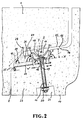
- the push-in socket connection consists of a sleeve (1), a spigot end (2) and an activatable sealing ring (3) made of elastomeric material (rubber or rubber-like plastic).
- the tip end has a groove (4; groove depth v, groove width w) with flanks (5, 6), the flank angle ⁇ expediently being 60 ° to 90 ° (reference line X as an extension of the groove base 7).
- the flanks are inclined here ( ⁇ approx. 80 °).
- the point end (2) is provided in the area between its end face (8) and the activatable sealing ring (3) with an inclined flank (9), the opposite flank flank (10) running at the same angle.
- flank angle ⁇ is expediently 20 ° to 45 ° (reference line X) in this cone region of the tip end and the socket, a flank angle of approximately 35 ° occurring here. In this way, a slight centering of the tip end is possible, which in turn contributes to an increase in the sealing effect.
- the mirror-symmetrical sealing profile (mirror plane Y) consists of a base part (3a), two side parts (3b) tangent to the groove flanks and a deformable front part, whereby in the non-activated state this front part is designed in such a way that the two arcuate edge parts (3c) have the same height (i.e. maximum Sealing height ⁇ groove depth v) with the tip end surface (16), while the arcuate inner part (3d) is inside the groove (17).
- the average wall thickness of the sealing ring parts (3a, 3b, 3c, 3d) is 2 to 5 mm.
- the inner part (3d) itself is provided on the outside with tooth-shaped (possibly dovetail-shaped) projections (18) and is arranged in the non-activated state with approximately half the groove depth v inside the groove (17). Because the edge parts (3c) of the sealing ring in the non-activated state are at the same level as the tip end surface (16), there is no mechanical attack on the elastomer body when joining the socket and the tip end of the pipe.
- the line (11) is connected to the cavity (12) by means of a flange (19) which bears on the inside of the sealing ring base part (3a).
- the flange itself contributes to an effective anchoring of the activatable sealing ring (3).
- the closable part (valve 20) of the line is here in an inner tube bore (21).
- the tip end (23) has two grooves (17, 24) which merge into one another in a step-like manner.
- the depth v 'of the groove (24) is ⁇ half the depth v of the groove (17), while the groove width w' is approximately equal to the groove width w.
- the presence of the additional groove (24) shortens the inclined flank (25) of the tip end (23) in the cone area.
- this groove (24) there is a pre-sealing ring (26) in the form of a solid elastomer body, etc. with simultaneous contact with the sealing ring side part (3b), the contact surface (27) between the two elastomer bodies being inclined.
- the angle ⁇ (reference line X) of this contact surface is approximately equal to the flank angle ⁇ (here approximately 80 °) of the groove (17).
- the pre-sealing ring (26) itself has a sealing lip (28) which is inclined in the direction of the activatable sealing ring (3).
- the outer surface (29) of the pre-sealing ring located in the cone area of the tip end and sleeve has the same angle of inclination (reference line X) as the tip end flank (25) or the opposite sleeve surface (10), the angle ⁇ here again being approximately 35 °.
- the activatable sealing ring (3) and the pre-sealing ring (26) consist of ethylene-propylene-diene copolymer (EPDM) or a blend of styrene-butadiene rubber (SBR) and natural rubber (NR).
- the pre-sealing ring (26) has a Shore A hardness of 35 ° to 65 °.
- the activatable sealing ring (3) expediently has two lines at a certain ring spacing (in particular half the ring circumference), one line being located at the high point of the ring. It is filled from below, while the air enclosed in the activatable ring escapes from above. As soon as the air has escaped, the upper valve is closed and the pressure is increased further (e.g. up to 1 bar).
Landscapes
- Engineering & Computer Science (AREA)
- General Engineering & Computer Science (AREA)
- Mechanical Engineering (AREA)
- Physics & Mathematics (AREA)
- Fluid Mechanics (AREA)
- Health & Medical Sciences (AREA)
- Life Sciences & Earth Sciences (AREA)
- Hydrology & Water Resources (AREA)
- Public Health (AREA)
- Water Supply & Treatment (AREA)
- Joints With Sleeves (AREA)
- Quick-Acting Or Multi-Walled Pipe Joints (AREA)
Claims (17)
- Raccord à emboîtement, destine à être mis en oeuvre en particulier dans la construction d'égouts, se composant- d'un manchon (1) en un matériau durci, à savoir en béton, en béton armé ou en résine synthétique,- d'une extrémité mâle (2) d'un tuyau en tant que partie emboîtée et- d'un anneau d'étanchéité (3) en matière élastomère, qui présente une cavité intérieure (12), l'anneau d'étanchéité (3) pouvant être mis dans un état activé, à partir d'un état non activé, par injection d'air ou d'un agent plastique ou élastique en permanence dans sa cavité, à travers au moins une conduite obturable (11), et un interstice résiduel (15), qui subsiste entre le manchon et l'extrémité mâle, pouvant être comblé et ainsi rendu étanche par la déformation de l'anneau d'étanchéité qui se produit alors;- l'extrémité mâle (2) présentant un flanc incliné (9) dans la région située entre sa surface frontale (8) et l'anneau d'étanchéité activable (3), et le flanc opposé (10) du manchon s'étendant sous le même angle;- l'extrémité mâle (2) présentant une gorge (4) de profondeur v et de largeur w, qui comporte des flancs (5, 6) et dans laquelle se trouve l'anneau d'étanchéité (3), lequel se compose d'une partie de base (3a) correspondant à la largeur w de la gorge, de deux parties latérales (3b) tangentes aux flancs (5, 6) de la gorge et d'une partie frontale déformable qui, à l'état non activé, se raccorde de chaque côté, par une partie de bord (3c) en arc de cercle, à la partie latérale (3b) adjacente, la hauteur maximale des parties de bord (3c) correspondant à la profondeur v de la gorge et ces parties de bord étant ainsi de niveau avec la surface (16) de l'extrémité mâle (2), tandis que la partie frontale s'étend en arc de cercle dans la gorge (4) à peu près jusqu'à la moitié de la profondeur v de celle-ci; et- la conduite (11), qui s'étend à l'intérieur de l'extrémité mâle (2), étant en communication avec la cavité (12) de l'anneau d'étanchéité par une ouverture dans la partie de base (3a) de celui-ci, la partie obturable (13) de la conduite se trouvent au niveau de la surface intérieure (14) du tuyau.
- Raccord à emboîtement, destiné à être mis en oeuvre en particulier dans la construction d'égouts, se composant- d'un manchon (1) en un matériau durci, à savoir en béton, en béton armé ou en résine synthétique,- d'une extrémité mâle (23) d'un tuyau en tant que partie emboîtée et- d'un anneau d'étanchéité (3) en matière élastomère, qui présente une cavité intérieure (12), l'anneau d'étanchéité (3) pouvant être mis dans un état activé, à partir d'un état non activé, par injection d'air ou d'un agent plastique ou élastique en permanence dans sa cavité, à travers au moins une conduite obturable (11), et un interstice résiduel (15), qui subsiste entre le manchon et l'extrémité mâle, pouvant être comblé et ainsi rendu étanche par la déformation de l'anneau d'étanchéité qui se produit alors;- l'extrémité mâle (23) présentant un flanc incliné (25) dans la région située entre sa surface frontale (8) et l'anneau d'étanchéité activable (3), et le flanc opposé (10) du manchon s'étendant sous le même angle;- l'extrémité mâle (23) présentant une gorge (17) de profondeur v et de largeur w, qui comporte un flanc (5) et dans laquelle se trouve l'anneau d'étanchéité (3), lequel se compose d'une partie de base (3a) correspondant à la largeur w de la gorge, de deux parties latérales (3b) dont l'une est tangente au flanc (5) de la gorge, et d'une partie frontale déformable qui, à l'état non activé, se raccorde de chaque côté, par une partie de bord (3c) en arc de cercle, à la partie latérale (3b) adjacente, la hauteur maximale des parties de bord (3c) correspondant à la profondeur v de la gorge et ces parties de bord étant ainsi de niveau avec la surface (16) de l'extrémité mâle (23), tandis que la partie frontale s'étend en arc de cercle dans la gorge (17) à peu près jusqu'à la moitié de le profondeur v de celle-ci;- un pré-anneau d'étanchéité (26), sous forme d'un corps plein en élastomère, se trouvant entre l'anneau d'étanchéité activable (3) et la surface frontale (8) de l'extrémité mâle, le pré-anneau d'étanchéité étant placé dans une gorge (24) de profondeur v' et de largeur w' qui se transforme en la gorge (17) en formant un gradin, et étant ainsi en même temps en contact avec l'autre partie latérale (3b) de l'anneau d'étanchéité activable, la surface extérieure (29) du pré-anneau d'étanchéité, qui se trouve dans la région conique de l'extrémité mâle et du manchon, étant inclinée, cette surface extérieure (29) présentant le même angle d'inclinaison que le flanc (25) de l'extrémité mâle ou que le flanc (10) du manchon; et- la conduite (11), qui s'étend à l'intérieur de l'extrémité mâle (23), étant en communication avec la cavité (12) de l'anneau d'étanchéité par une ouverture dans la partie de base (3a) de celui-ci, la partie obturable (20) de la conduite se trouvant au niveau de la surface intérieure (14) du tuyau.
- Raccord à emboîtement selon la revendication 1 ou 2, caractérisé en ce que la partie interne (3d) de l'anneau d'étanchéité présente, du côté extérieur, des saillies (18) en forme de dents ou de queues d'aronde.
- Raccord à emboîtement selon la revendication 2 ou 3, caractérisé en ce que le pré-anneau d'étanchéité (26) comporte une lèvre d'étanchéité (28) qui est inclinée en direction de l'anneau d'étanchéité activable (3).
- Raccord à emboîtement selon l'une quelconque des revendications 2 à 4, caractérisé en ce que le pré-anneau d'étanchéité (26) présente une dureté Shore A de 35° à 65°.
- Raccord à emboîtement selon l'une quelconque des revendications 2 à 5, caractérisé en ce que l'angle γ de la surface de contact (27) entre les deux corps en élastomère est à peu près égal à l'angle α du flanc de la gorge (4, 17).
- Raccord à emboîtement selon l'une quelconque des revendications 2 à 6, caractérisé en ce que la profondeur v' de la gorge est inférieure ou égale à la moitié de la profondeur v de l'autre gorge.
- Raccord à emboîtement selon l'une quelconque des revendications 2 à 7, caractérisé en ce que la largeur w' de la gorge est à peu près égale à la largeur w de l'autre gorge.
- Raccord à emboîtement selon l'une quelconque des revendications 1 à 8, caractérisé en ce que l'angle α des flancs a une valeur comprise entre 60° et 90°.
- Raccord à emboîtement selon l'une quelconque des revendications 1 à 9, caractérisé en ce que, dans la région conique de l'extrémité mâle (2, 23) et du manchon (1), l'angle β des flancs (9, 10, 25) et de la surface extérieure (29) du pré-anneau d'étanchéité a une valeur comprise entre 20° et 45°.
- Raccord à emboîtement selon l'une quelconque des revendications 1 à 10, caractérisé en ce que l'épaisseur moyenne de paroi des parties (3a, 3b, 3c, 3d) de l'anneau d'étanchéité est comprise entre 2 et 5 mm.
- Raccord à emboîtement selon l'une quelconque des revendications 1 à 11, caractérisé en ce que l'anneau d'étanchéité activable (3) et le pré-anneau d'étanchéité (27) sont en un copolymère éthylène/propylène/diène (EPDM) ou en un mélange de caoutchouc styrène/butadiène (SBR) et de caoutchouc naturel (NR).
- Raccord à emboîtement selon l'une quelconque des revendications 1 à 12, caractérisé en ce que la conduite (11) débouche dans la cavité (12) au milieu de la gorge.
- Raccord à emboîtement selon l'une quelconque des revendications 1 à 13, caractérisé en ce que le raccordement de la conduite s'effectue au moyen d'une bride (19) qui est appliquée du côté intérieur sur la partie de base (3a) de l'anneau d'étanchéité.
- Raccord à emboîtement selon l'une quelconque des revendications 1 à 14, caractérisé en ce que la partie obturable (13) de la conduite est à fleur de la surface intérieure (14) du tuyau.
- Raccord à emboîtement selon l'une quelconque des revendications 1 à 14, caractérisé en ce que la partie obturable (20) de la conduite se trouve dans un creux (21) de la surface intérieure du tuyau.
- Raccord à emboîtement selon l'une quelconque des revendications 1 à 16, caractérisé en ce que l'anneau d'étanchéité activable (3) comporte deux conduites qui sont disposées à une distance déterminée dans l'anneau (en particulier à la demi-circonférence de l'anneau), l'une des conduites se trouvant au point haut de l'anneau.
Applications Claiming Priority (2)
| Application Number | Priority Date | Filing Date | Title |
|---|---|---|---|
| DE9013603 | 1990-09-28 | ||
| DE9013603U | 1990-09-28 |
Publications (3)
| Publication Number | Publication Date |
|---|---|
| EP0479172A2 EP0479172A2 (fr) | 1992-04-08 |
| EP0479172A3 EP0479172A3 (en) | 1992-05-13 |
| EP0479172B1 true EP0479172B1 (fr) | 1995-07-19 |
Family
ID=6857898
Family Applications (1)
| Application Number | Title | Priority Date | Filing Date |
|---|---|---|---|
| EP91116614A Expired - Lifetime EP0479172B1 (fr) | 1990-09-28 | 1991-09-28 | Raccord avec manchon à garniture |
Country Status (3)
| Country | Link |
|---|---|
| EP (1) | EP0479172B1 (fr) |
| DE (1) | DE59106017D1 (fr) |
| ES (1) | ES2077131T3 (fr) |
Cited By (2)
| Publication number | Priority date | Publication date | Assignee | Title |
|---|---|---|---|---|
| WO2001090626A1 (fr) | 2000-05-24 | 2001-11-29 | Rg Rohrgruppe Gmbh & Co. Kg | Systeme d'etancheite pour tubes-guides |
| WO2002097240A1 (fr) | 2001-05-30 | 2002-12-05 | Phoenix Ag | Ensemble d'etancheite |
Families Citing this family (5)
| Publication number | Priority date | Publication date | Assignee | Title |
|---|---|---|---|---|
| DE19644357C2 (de) * | 1996-10-25 | 2000-11-16 | Sendenhorst Kunststoffroehren | Schlauchdichtung |
| US6015169A (en) * | 1996-03-25 | 2000-01-18 | Kunst-Stoffrohren Sedenhorst Gmbh | Connector for concrete pipes |
| DE10158155A1 (de) * | 2000-12-01 | 2002-06-06 | Phoenix Ag | Dichtanordnung einer Rohrverbindung, insbesondere Vortriebsrohrverbindung |
| EP1295063B1 (fr) * | 2001-05-11 | 2005-08-31 | Phoenix AG | Systeme d'etancheite et son procede de realisation |
| DE102012113089A1 (de) * | 2012-12-26 | 2014-06-26 | Hans Bohnet | Verfahren zum Abdichten eines Rohrleitungssystems |
Family Cites Families (20)
| Publication number | Priority date | Publication date | Assignee | Title |
|---|---|---|---|---|
| DE1299183B (de) | 1967-10-28 | 1969-07-10 | Denso Chemie Gmbh | Verfahren zur Montage von elastischen Roll-Dichtringen fuer Glockenmuffenrohrverbindungen und elastischer Dichtring |
| DE2140546C3 (de) | 1971-08-12 | 1974-08-01 | Fa. Ch. Heinrich Gueltig, 7100 Heilbronn | Verfahren zur Herstellung eines Entwässerungsformsteins und Vorrichtung zu seiner Durchführung |
| FR2153612A5 (fr) * | 1971-09-17 | 1973-05-04 | Pont A Mousson Fond | |
| BE790520A (fr) | 1971-10-25 | 1973-02-15 | Forsheda Ideutveckling Ab | Section de tuyau, de preference en beton avec bague d'etancheite |
| SE412797B (sv) | 1978-09-08 | 1980-03-17 | Forsheda Gummifabrik Ab | Sett for framstellning av ror foretredesvis betongror |
| DE3136183A1 (de) | 1981-09-12 | 1983-03-31 | Denso-Chemie Wedekind Kg, 5090 Leverkusen | Dichtungsanordnung fuer eine muffenverbindung an rohren |
| DE8319494U1 (de) | 1983-07-06 | 1984-12-13 | Denso-Chemie Wedekind Kg, 5090 Leverkusen | Steckmuffendichtung fuer betonrohre mit an der rohrglocke befestigtem dichtungselement |
| DE3406505A1 (de) | 1984-02-23 | 1985-08-29 | Phoenix Ag, 2100 Hamburg | Steckverbindung fuer muffe und spitzende von beton- und steinzeugrohren |
| DE3414180A1 (de) | 1984-04-14 | 1985-10-24 | Georg Prinzing GmbH & Co KG Betonformen- und Maschinenfabrik, 7902 Blaubeuren | Dichtungseinrichtung fuer aneinanderstossende, zumindest etwa rohrfoermige bauteile, insbesondere fuer betonformteile |
| DE3422483A1 (de) | 1984-06-16 | 1985-12-19 | Phoenix Ag, 2100 Hamburg | Form zum herstellen eines muffenrohres |
| DE8425094U1 (de) | 1984-08-24 | 1984-11-29 | Phoenix Ag, 2100 Hamburg | Form zum Herstellen eines Muffenrohres |
| DE3507909A1 (de) | 1985-03-06 | 1986-09-11 | Phoenix Ag, 2100 Hamburg | Form zum herstellen eines muffenrohres |
| DE3617466A1 (de) | 1986-05-23 | 1987-11-26 | Muecher Hermann Gmbh | Muffenschalung zum fertigen von steckmuffen an rohren |
| DE3624831A1 (de) | 1986-07-23 | 1988-01-28 | Muecher Hermann Gmbh | Muffenschalung fuer rohre |
| DE3638547A1 (de) | 1986-11-11 | 1988-05-19 | Muecher Hermann Gmbh | Variable muffenschalung fuer betonrohre |
| DE3828971A1 (de) * | 1987-09-09 | 1989-03-23 | Phoenix Ag | Dichtring zum abdichten von gfk-rohren |
| AU594560B2 (en) | 1988-03-14 | 1990-03-08 | Forsheda Ab | A device for moulding a pipe socket |
| DE3815455C2 (de) | 1988-05-06 | 1994-10-20 | Freudenberg Carl Fa | Aufblasbare Dichtung |
| DE9004616U1 (de) | 1989-05-04 | 1990-07-12 | Phoenix Ag, 2100 Hamburg | Hilfsring |
| DE9116780U1 (de) | 1990-03-24 | 1993-10-14 | Albert Steinhoff GmbH, 48301 Nottuln | Steckmuffenverbindung |
-
1991
- 1991-09-28 EP EP91116614A patent/EP0479172B1/fr not_active Expired - Lifetime
- 1991-09-28 DE DE59106017T patent/DE59106017D1/de not_active Expired - Fee Related
- 1991-09-28 ES ES91116614T patent/ES2077131T3/es not_active Expired - Lifetime
Cited By (2)
| Publication number | Priority date | Publication date | Assignee | Title |
|---|---|---|---|---|
| WO2001090626A1 (fr) | 2000-05-24 | 2001-11-29 | Rg Rohrgruppe Gmbh & Co. Kg | Systeme d'etancheite pour tubes-guides |
| WO2002097240A1 (fr) | 2001-05-30 | 2002-12-05 | Phoenix Ag | Ensemble d'etancheite |
Also Published As
| Publication number | Publication date |
|---|---|
| EP0479172A2 (fr) | 1992-04-08 |
| EP0479172A3 (en) | 1992-05-13 |
| ES2077131T3 (es) | 1995-11-16 |
| DE59106017D1 (de) | 1995-08-24 |
Similar Documents
| Publication | Publication Date | Title |
|---|---|---|
| EP0449082B1 (fr) | Raccord à manchon | |
| EP0273221B1 (fr) | Raccord de tuyaux avec manchon et pièce enfichable | |
| EP1143183A2 (fr) | Bague d'étanchéité entre l' embout d'un tuyau annelé extérieurement et un manchon ayant une surface intérieure lisse | |
| DE1475688A1 (de) | Klemmvorrichtung,insbesondere fuer Rohrleitungen | |
| EP0795712B1 (fr) | Dispositif de raccordement | |
| EP0479172B1 (fr) | Raccord avec manchon à garniture | |
| DE3026681A1 (de) | Fluessigkeitsdichte verbindung | |
| DE9112112U1 (de) | Steckmuffenverbindung | |
| EP1151220B1 (fr) | Accouplement de tuyaux destine a des tuyaux plastique | |
| EP0629262B1 (fr) | Joint profile d'etancheite pour segments tubulaires de tunnels, notamment pour elements mis en place par flottaison | |
| DE3507909C2 (fr) | ||
| DE69132127T2 (de) | Rohrverbindung | |
| DE202019104525U1 (de) | Anschlussstück zum Anschluss eines Kunststoffrohrs an ein mineralisches Kanalrohr | |
| CH686383A5 (de) | Verfahren zur Herstellung einer nicht verschiebbaren Dichtungsprofilleiste und nach diesem Verfahren hergestellte Leiste. | |
| EP1359360B1 (fr) | Joint d'étanchéité pour un raccord à manchon | |
| EP0347608B1 (fr) | Joint d'étanchéité | |
| DE4114232C2 (de) | Haltemittel für Dichtungen in Muffenverbindungen für Rohre oder Profile | |
| DE2441118A1 (de) | Abdichtung an profilbauteilen | |
| DE9412445U1 (de) | Unlösbare Rohrverbindung | |
| EP1337778B1 (fr) | Ensemble d'etancheite pour un raccord de tuyaux, notamment un raccord de tuyaux d'avancement | |
| DE9316367U1 (de) | Rohrmuffe | |
| EP1591712A2 (fr) | Tuyau de connection et sa application | |
| DE4004754A1 (de) | Dichtungseinrichtung fuer eine rohrverbindung | |
| DE9217222U1 (de) | Abdichtung an zusammensteckbaren Betonfertigteilen | |
| DE60309311T2 (de) | Rohrabzweigung mit buchse mit einer keilförmigen nut und keil zum einführen in die buchse |
Legal Events
| Date | Code | Title | Description |
|---|---|---|---|
| PUAI | Public reference made under article 153(3) epc to a published international application that has entered the european phase |
Free format text: ORIGINAL CODE: 0009012 |
|
| PUAL | Search report despatched |
Free format text: ORIGINAL CODE: 0009013 |
|
| AK | Designated contracting states |
Kind code of ref document: A2 Designated state(s): BE DE ES FR GB IT |
|
| AK | Designated contracting states |
Kind code of ref document: A3 Designated state(s): BE DE ES FR GB IT |
|
| 17P | Request for examination filed |
Effective date: 19920427 |
|
| GBC | Gb: translation of claims filed (gb section 78(7)/1977) | ||
| 17Q | First examination report despatched |
Effective date: 19930706 |
|
| GRAA | (expected) grant |
Free format text: ORIGINAL CODE: 0009210 |
|
| RAP1 | Party data changed (applicant data changed or rights of an application transferred) |
Owner name: ALBERT STEINHOFF GMBH Owner name: PHOENIX AKTIENGESELLSCHAFT |
|
| RIN1 | Information on inventor provided before grant (corrected) |
Inventor name: STEINHOFF JUN., ALBERT, DIPL.-ING. Inventor name: GRABE, WERNER, DR.-ING. Inventor name: DREIER, BERNHARD |
|
| AK | Designated contracting states |
Kind code of ref document: B1 Designated state(s): BE DE ES FR GB IT |
|
| REF | Corresponds to: |
Ref document number: 59106017 Country of ref document: DE Date of ref document: 19950824 |
|
| ET | Fr: translation filed | ||
| ITF | It: translation for a ep patent filed | ||
| GBT | Gb: translation of ep patent filed (gb section 77(6)(a)/1977) |
Effective date: 19950914 |
|
| REG | Reference to a national code |
Ref country code: ES Ref legal event code: FG2A Ref document number: 2077131 Country of ref document: ES Kind code of ref document: T3 |
|
| PLBE | No opposition filed within time limit |
Free format text: ORIGINAL CODE: 0009261 |
|
| STAA | Information on the status of an ep patent application or granted ep patent |
Free format text: STATUS: NO OPPOSITION FILED WITHIN TIME LIMIT |
|
| 26N | No opposition filed | ||
| REG | Reference to a national code |
Ref country code: GB Ref legal event code: IF02 |
|
| PGFP | Annual fee paid to national office [announced via postgrant information from national office to epo] |
Ref country code: DE Payment date: 20070824 Year of fee payment: 17 |
|
| PG25 | Lapsed in a contracting state [announced via postgrant information from national office to epo] |
Ref country code: DE Free format text: LAPSE BECAUSE OF NON-PAYMENT OF DUE FEES Effective date: 20090401 |
|
| PGFP | Annual fee paid to national office [announced via postgrant information from national office to epo] |
Ref country code: ES Payment date: 20090922 Year of fee payment: 19 |
|
| PGFP | Annual fee paid to national office [announced via postgrant information from national office to epo] |
Ref country code: GB Payment date: 20090922 Year of fee payment: 19 |
|
| PGFP | Annual fee paid to national office [announced via postgrant information from national office to epo] |
Ref country code: IT Payment date: 20090926 Year of fee payment: 19 |
|
| PGFP | Annual fee paid to national office [announced via postgrant information from national office to epo] |
Ref country code: BE Payment date: 20091023 Year of fee payment: 19 |
|
| BERE | Be: lapsed |
Owner name: *PHOENIX A.G. Effective date: 20100930 Owner name: ALBERT *STEINHOFF G.M.B.H. Effective date: 20100930 |
|
| GBPC | Gb: european patent ceased through non-payment of renewal fee |
Effective date: 20100928 |
|
| PG25 | Lapsed in a contracting state [announced via postgrant information from national office to epo] |
Ref country code: IT Free format text: LAPSE BECAUSE OF NON-PAYMENT OF DUE FEES Effective date: 20100928 |
|
| REG | Reference to a national code |
Ref country code: FR Ref legal event code: ST Effective date: 20110531 |
|
| PG25 | Lapsed in a contracting state [announced via postgrant information from national office to epo] |
Ref country code: BE Free format text: LAPSE BECAUSE OF NON-PAYMENT OF DUE FEES Effective date: 20100930 Ref country code: FR Free format text: LAPSE BECAUSE OF NON-PAYMENT OF DUE FEES Effective date: 20100930 |
|
| PG25 | Lapsed in a contracting state [announced via postgrant information from national office to epo] |
Ref country code: GB Free format text: LAPSE BECAUSE OF NON-PAYMENT OF DUE FEES Effective date: 20100928 |
|
| PGFP | Annual fee paid to national office [announced via postgrant information from national office to epo] |
Ref country code: FR Payment date: 20091001 Year of fee payment: 19 |
|
| REG | Reference to a national code |
Ref country code: ES Ref legal event code: FD2A Effective date: 20111019 |
|
| PG25 | Lapsed in a contracting state [announced via postgrant information from national office to epo] |
Ref country code: ES Free format text: LAPSE BECAUSE OF NON-PAYMENT OF DUE FEES Effective date: 20100929 |