EP0445340B1 - Valve with piezoelectric drive - Google Patents
Valve with piezoelectric drive Download PDFInfo
- Publication number
- EP0445340B1 EP0445340B1 EP90104537A EP90104537A EP0445340B1 EP 0445340 B1 EP0445340 B1 EP 0445340B1 EP 90104537 A EP90104537 A EP 90104537A EP 90104537 A EP90104537 A EP 90104537A EP 0445340 B1 EP0445340 B1 EP 0445340B1
- Authority
- EP
- European Patent Office
- Prior art keywords
- valve
- leg
- piezoelectric actuator
- change
- piezoceramic element
- Prior art date
- Legal status (The legal status is an assumption and is not a legal conclusion. Google has not performed a legal analysis and makes no representation as to the accuracy of the status listed.)
- Expired - Lifetime
Links
Images
Classifications
-
- F—MECHANICAL ENGINEERING; LIGHTING; HEATING; WEAPONS; BLASTING
- F02—COMBUSTION ENGINES; HOT-GAS OR COMBUSTION-PRODUCT ENGINE PLANTS
- F02M—SUPPLYING COMBUSTION ENGINES IN GENERAL WITH COMBUSTIBLE MIXTURES OR CONSTITUENTS THEREOF
- F02M51/00—Fuel-injection apparatus characterised by being operated electrically
- F02M51/06—Injectors peculiar thereto with means directly operating the valve needle
- F02M51/0603—Injectors peculiar thereto with means directly operating the valve needle using piezoelectric or magnetostrictive operating means
Definitions
- the present invention relates to a valve with a piezoelectric drive.
- valves with short response times are required.
- injection valves with extremely short opening and closing times are required to achieve short injection times (less than 0.2 ms). Valves that close slowly tend to form droplets and offer low metering accuracy.
- the injection valves designed according to the prior art generally have a valve drive based on the electromagnetic principle. Such a valve is opened by an electromagnet. A return spring closes the valve after the excitation current is switched off. In order to achieve a short opening time, such valves are briefly activated with a high pulse of high excitation current before switching to the lower holding current. In electromagnetic valves with a single solenoid coil, the closing process cannot be influenced electrically because of the quadratic current / force behavior. It depends only on the spring constant of the required return spring and the mass of the valve needle to be moved.
- JP-A-62/22 86 64 which shows a generic valve, discloses a fuel injection valve for internal combustion engines provided with a piezoelectric drive element. A corresponding lever is used to increase the valve lift.
- the invention is based on the finding that by using a piezoelectric drive with an approximately linear relationship between the control voltage for a piezoelectric actuator and the deflection caused, the valve can be actively opened and closed in order to achieve short and defined opening and closing times. As a result, the desired proportionality of the injection quantity to the injection time can be achieved even with very short injection times.
- a disadvantage of piezoelectric displacement sensors is that only relatively small deflections (1-2%) can be achieved, so that they cannot be used directly as an actuator for valves.
- the present invention has for its object to provide a valve of the type mentioned, which is simple and inexpensive to manufacture and meets the requirement of extremely short response times with defined achievable valve positions.
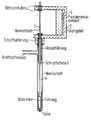
- the valve is driven by a rod-shaped piezoceramic element 1 which acts as a piezoelectric actuator and which preferably has a square cross section and is formed with the dimensions 10 mm ⁇ 10 mm ⁇ 32 mm. It is controlled with a voltage of up to 150 V and achieves a deflection of 40 ⁇ m at 150 V.
- the piezoelectric actuator is clamped on the inner side of a U-shaped spring-hard steel fork 2, cf. the figure. When the piezoelectric actuator is deflected, the free ends of the steel fork 2 are pressed apart by the lever action that occurs.
- the steel fork 2 is preferably designed such that the change in distance between the free ends thereof is higher by a factor of 4 than the change in surface distance in question of the piezoelectric actuator.
- a 100 mm long valve stem 4 at the front end of which the valve seat is located, is firmly attached to a bushing.
- a valve tappet 1 which is inserted through the bushing and is guided in the valve stem 4 and at the front end of which there is a valve needle.
- the valve stem 4 and the valve lifter 1 can be displaced relative to one another.
- the valve tappet 3 is sealed at the bushing.
- the fuel inlet is at the rear end of the valve stem 4.
- the valve needle When the piezoelectric actuator is not deflected, the valve needle is on the valve seat and thus closes the valve. If the piezoelectric actuator is deflected (40 ⁇ m maximum), the valve needle experiences a stroke of up to 160 ⁇ m due to the amplitude transformation of the steel fork 2 and opens the valve.
- the spring constant of the steel frame namely the steel fork 2
- the spring constant of the steel frame can be selected to be so high that the actuator is constantly under the mechanical prestress of the steel frame, even in the event of contraction. This means that the valve can also be actively closed.
- opening and closing times of less than 100 ⁇ s can be achieved. This behavior is sufficient even at an engine speed of 10,000 rpm. Due to the extremely short injection times ( ⁇ 0.2 ms), multiple injections per working cycle can advantageously be implemented, which can be used to optimize the combustion process as desired.
- the valve also has the advantage that the injection quantity can be controlled via the valve lift which is variable by the control voltage. This provides an additional possibility of fuel metering compared to injectors with only two fixed end positions of the valve needle.
- the drive system can be long Valve stem must be arranged relatively far (100 mm) from the valve seat in order to gain space for other components close to the engine.
Landscapes
- Engineering & Computer Science (AREA)
- Chemical & Material Sciences (AREA)
- Combustion & Propulsion (AREA)
- Mechanical Engineering (AREA)
- General Engineering & Computer Science (AREA)
- Fuel-Injection Apparatus (AREA)
- Electrically Driven Valve-Operating Means (AREA)
Abstract
Description
Die vorliegende Erfindung betrifft ein Ventil mit piezoelektrischem Antrieb.The present invention relates to a valve with a piezoelectric drive.
Bei bestimmten Steuerungsabläufen werden Ventile mit kurzen Reaktionszeiten benötigt. Insbesondere bei der elektronisch gesteuerten Kraftstoff-Einspritzung in Verbrennungsmotoren werden zum Erreichen von kurzen Einspritzzeiten (kleiner 0,2 ms) Einspritzventile mit extrem kleinen Öffnungs- und Schließzeiten benötigt. Ventile, die nur langsam schließen, neigen zur Tropfenbildung und bieten eine nur geringe Dosiergenauigkeit.With certain control processes, valves with short response times are required. In particular in the case of electronically controlled fuel injection in internal combustion engines, injection valves with extremely short opening and closing times are required to achieve short injection times (less than 0.2 ms). Valves that close slowly tend to form droplets and offer low metering accuracy.
Die nach dem Stand der Technik ausgeführten Einspritzventile weisen im allgemeinen einen Ventilantrieb nach dem elektromagnetischen Prinzip auf. Ein derartiges Ventil wird durch einen Elektromagneten geöffnet. Eine Rückstellfeder schließt das Ventil nach Abschalten des Erregungsstroms. Um eine kleine Öffnungszeit zu erreichen, werden derartige Ventile kurzzeitig mit einem hohen Impuls hoher Erregungsstromstärke angesteuert, bevor auf den niedrigeren Haltestrom umgeschaltet wird. Der Schließvorgang kann bei elektromagnetischen Ventilen mit einer einzigen Magnetspule wegen des quadratischen Strom/Kraft-Verhaltens elektrisch nicht beeinflußt werden. Er hängt einzig von der Federkonstanten der erforderlichen Rückstellfeder und der zu bewegenden Masse der Ventilnadel ab.The injection valves designed according to the prior art generally have a valve drive based on the electromagnetic principle. Such a valve is opened by an electromagnet. A return spring closes the valve after the excitation current is switched off. In order to achieve a short opening time, such valves are briefly activated with a high pulse of high excitation current before switching to the lower holding current. In electromagnetic valves with a single solenoid coil, the closing process cannot be influenced electrically because of the quadratic current / force behavior. It depends only on the spring constant of the required return spring and the mass of the valve needle to be moved.
Der Einsatz von piezoelektrischen Wandlern, die den elektroexpansiven Longitudinaleffekt zu antriebstechnischen Zwecken ausnutzen, ist aus der US Druckschrift US-A-4 435 666 bekannt.The use of piezoelectric transducers which use the electroexpansive longitudinal effect for drive purposes is known from US Pat. No. 4,435,666.
Weiterhin ist aus der Schrift JP-A-62/22 86 64, die ein gattungsbildendes Ventil zeigt, ein mit einem piezoelektrischen Antriebselement versehenes Kraftstoffeinspritz Ventil für Verbrennungsmotoren bekannt. Zur Vergrößerung des Ventilhubs wird ein entsprechender Hebel verwendet.Furthermore, JP-A-62/22 86 64, which shows a generic valve, discloses a fuel injection valve for internal combustion engines provided with a piezoelectric drive element. A corresponding lever is used to increase the valve lift.
Der Erfindung liegt die Erkenntnis zugrunde, daß durch Verwendung eines piezoelektrischen Antriebs mit einem annähernd linearen Zusammenhang zwischen der Ansteuerspannung für ein piezoelektrisches Stellglied und der bewirkten Auslenkung das Ventil aktiv zu öffnen und zu schließen ist, um kurze und definierte Öffnungs- und Schließzeiten zu erreichen. Dadurch kann die gewünschte Proportionalität der Einspritzmenge zur Einspritzzeit auch bei sehr kleinen Einspritzzeiten erreicht werden.The invention is based on the finding that by using a piezoelectric drive with an approximately linear relationship between the control voltage for a piezoelectric actuator and the deflection caused, the valve can be actively opened and closed in order to achieve short and defined opening and closing times. As a result, the desired proportionality of the injection quantity to the injection time can be achieved even with very short injection times.
Ein Nachteil piezoelektrischer Weggeber besteht jedoch darin, daß nur relativ kleine Auslenkungen (1 - 2 %o) erzielbar sind, so daß sie nicht unmittelbar als Stellglied für Ventile verwendbar sind.A disadvantage of piezoelectric displacement sensors, however, is that only relatively small deflections (1-2%) can be achieved, so that they cannot be used directly as an actuator for valves.
Der vorliegenden Erfindung liegt die Aufgabe zugrunde, ein Ventil der eingangs genannten Art zu schaffen, das auf einfache und kostengünstige Weise herstellbar ist und das Erfordernis extrem kleiner Reaktionszeiten bei definiert erzielbaren Ventilstellungen erfüllt.The present invention has for its object to provide a valve of the type mentioned, which is simple and inexpensive to manufacture and meets the requirement of extremely short response times with defined achievable valve positions.
Zur Lösung dieser Aufgabe wird ein Ventil gemäß dem Patentanspruch 1 vorgeschlagen.To solve this problem, a valve according to claim 1 is proposed.
Vorteilhafte Weiterbildungen der Erfindung sind durch die in den Unteransprüchen angegebenen Merkmale gekennzeichnet.Advantageous developments of the invention are characterized by the features specified in the subclaims.
Im folgenden wird die Erfindung im einzelnen anhand einer ein bevorzugtes Ausführungsbeispiel betreffenden Figur beschrieben.The invention is described in detail below with reference to a figure relating to a preferred exemplary embodiment.
Erfindungsgemäß erfolgt der Antrieb des Ventils durch ein stabförmiges, als piezoelektrisches Stellglied fungierendes Piezokeramikelement 1, das vorzugsweise einen quadratischen Querschnitt hat und mit den Abmessungen 10 mm x 10 mm x 32 mm ausgebildet ist. Es wird mit einer Spannung bis zu 150 V angesteuert und erreicht bei 150 V eine Auslenkung von 40 µm. Zur Erhöhung der Auslenkung auf Werte, die zum Öffnen eines Einspritzventils typisch sind (100 µm), ist das piezoelektrische Stellglied an der inneren Seite einer U-förmigen federharten Stahlgabel 2 eingespannt, vergl. die Figur. Bei der Auslenkung des piezoelektrischen Stellgliedes werden die freien Enden der Stahlgabel 2 durch die auftretende Hebelwirkung auseinandergedrückt. Die Stahlgabel 2 ist vorzugsweise so ausgelegt, daß die Abstandsänderung zwischen den freien Enden derselben um den Faktor 4 höher als die betreffende Oberflächenabstandsänderung des piezoelektrischen Stellglieds ist. An einem der freien Enden der Stahlgabel 2 ist über einer Durchführung ein 100 mm langer Ventilschaft 4, an dessen vorderen Ende sich der Ventilsitz befindet, fest angebracht. An dem anderen freien Ende der Stahlgabel 2 ist ein Ventilstößel 1, der durch die Durchführung gesteckt und in dem Ventilschaft 4 geführt ist und an dessen vorderem Ende sich eine Ventilnadel befindet, befestigt. Der Ventilschaft 4 und der Ventilstößel 1 sind relativ gegeneinander verschiebbar. Im inneren Teil des Ventilschafts 4 ist der Ventilstößel 3 an der Durchführung abgedichtet. Der Kraftstoffeinlaß befindet sich an dem hinteren Ende des Ventilschafts 4.According to the invention, the valve is driven by a rod-shaped piezoceramic element 1 which acts as a piezoelectric actuator and which preferably has a square cross section and is formed with the dimensions 10 mm × 10 mm × 32 mm. It is controlled with a voltage of up to 150 V and achieves a deflection of 40 µm at 150 V. To increase the deflection to values that are typical for opening an injection valve (100 μm), the piezoelectric actuator is clamped on the inner side of a U-shaped spring-
Im nicht ausgelenkten Zustand des piezoelektrischen Stellgliedes befindet sich die Ventilnadel am Ventilsitz und schließt somit das Ventil. Ist das piezoelektrische Stellglied ausgelenkt (40 µm maximal), so erfährt die Ventilnadel durch die Amplitudentransformation der Stahlgabel 2 einen Hub bis zu 160 µm und öffnet das Ventil.When the piezoelectric actuator is not deflected, the valve needle is on the valve seat and thus closes the valve. If the piezoelectric actuator is deflected (40 µm maximum), the valve needle experiences a stroke of up to 160 µm due to the amplitude transformation of the
Durch die sehr hohe Blockierkraft des piezoelektrischen Stellgliedes kann die Federkonstante des Stahlrahmens, nämlich der Stahlgabel 2, so hoch gewählt werden, daß das Stellglied ständig - auch bei Kontraktion - unter der mechanischen Vorspannung des Stahlrahmens steht. Somit kann das Ventil auch aktiv geschlossen werden.Due to the very high blocking force of the piezoelectric actuator, the spring constant of the steel frame, namely the
Mit dem beschriebenen Ventil lassen sich Öffnungs- und Schließzeiten von kleiner als 100 µs realisieren. Dieses Verhalten ist selbst bei einer Motordrehzahl von 10 000 U/min ausreichend. Durch die extrem kurzen Einspritzzeiten (< 0,2 ms) lassen sich vorteilhafterweise Mehrfacheinspritzungen je Arbeitsspiel realisieren, was zu einer gewünschten Optimierung des Verbrennungsvorgangs benutzt werden kann.With the valve described, opening and closing times of less than 100 µs can be achieved. This behavior is sufficient even at an engine speed of 10,000 rpm. Due to the extremely short injection times (<0.2 ms), multiple injections per working cycle can advantageously be implemented, which can be used to optimize the combustion process as desired.
Das Ventil hat darüber hinaus den Vorteil, daß die Einspritzmenge über den durch die Ansteuerspannung variablen Ventilhub gesteuert werden kann. Dadurch ist im Vergleich zu Einspritzventilen mit nur zwei festen Endlagen der Ventilnadel eine zusätzliche Möglichkeit der Kraftstoffdosierung gegeben.The valve also has the advantage that the injection quantity can be controlled via the valve lift which is variable by the control voltage. This provides an additional possibility of fuel metering compared to injectors with only two fixed end positions of the valve needle.
Aufgrund der hohen Blockierkraft des piezoelektrischen Stellgliedes kann das Antriebssystem durch einen langen Ventilschaft relativ weit (100 mm) vom Ventilsitz entfernt angeordnet sein, um einen Raumgewinn für andere, motornahe Komponenten zu erzielen.Due to the high blocking force of the piezoelectric actuator, the drive system can be long Valve stem must be arranged relatively far (100 mm) from the valve seat in order to gain space for other components close to the engine.
Claims (5)
- Valve with a valve stem (4) which has a valve seat, a valve plunger (1) which is mounted so as to be displaceable relative to the valve stem (4), and a lever mechanism which acts on the valve plunger (1) and which contains a piezoelectric actuator (3), characterized in that the lever mechanism comprises a U-shaped frame (2), in that the piezoelectric actuator (3) is clamped between a first leg and a second leg of the frame (2), in that the valve stem (4) is attached to the free end of the first leg, and in that the valve plunger (1) is mounted on the free end of the second leg and projects through a lead-through bushing provided in the first leg.
- Valve according to Claim 1, characterized in that a piezoceramic element (3) having a characteristic with an approximately linear correlation between a drive voltage and a change in the spacing of the surface of the piezoceramic element caused by this drive voltage and thus the deflection of the valve plunger (1) is used as the piezoelectric actuator.
- Valve according to Claim 1 or Claim 2, characterized in that the U-shaped frame (2) is made of steel and is designed in such a way that the change in spacing between the free ends of the two legs is higher by the factor 4 than the change in the spacing of the surface of the piezoceramic element (3).
- Valve according to any one of the preceding claims, characterized in that the piezoceramic element (3) is in the form of a rod-shaped square-sectioned body having the dimensions 10 mm x 10 mm x 32 mm, and undergoes a 40 µm change in length when a voltage of 150 volts is applied.
- Use of a valve according to any one of the preceding claims as a fuel injection valve.
Priority Applications (5)
| Application Number | Priority Date | Filing Date | Title |
|---|---|---|---|
| DE59008025T DE59008025D1 (en) | 1990-03-09 | 1990-03-09 | Valve with a piezoelectric actuator. |
| AT90104537T ATE115683T1 (en) | 1990-03-09 | 1990-03-09 | VALVE WITH PIEZOELECTRIC ACTUATOR. |
| EP90104537A EP0445340B1 (en) | 1990-03-09 | 1990-03-09 | Valve with piezoelectric drive |
| US07/652,541 US5094429A (en) | 1990-03-09 | 1991-02-08 | Valve having piezoelecrtric drive |
| JP3069315A JPH04224269A (en) | 1990-03-09 | 1991-03-08 | Valve with piezoelectric drive |
Applications Claiming Priority (1)
| Application Number | Priority Date | Filing Date | Title |
|---|---|---|---|
| EP90104537A EP0445340B1 (en) | 1990-03-09 | 1990-03-09 | Valve with piezoelectric drive |
Publications (2)
| Publication Number | Publication Date |
|---|---|
| EP0445340A1 EP0445340A1 (en) | 1991-09-11 |
| EP0445340B1 true EP0445340B1 (en) | 1994-12-14 |
Family
ID=8203739
Family Applications (1)
| Application Number | Title | Priority Date | Filing Date |
|---|---|---|---|
| EP90104537A Expired - Lifetime EP0445340B1 (en) | 1990-03-09 | 1990-03-09 | Valve with piezoelectric drive |
Country Status (5)
| Country | Link |
|---|---|
| US (1) | US5094429A (en) |
| EP (1) | EP0445340B1 (en) |
| JP (1) | JPH04224269A (en) |
| AT (1) | ATE115683T1 (en) |
| DE (1) | DE59008025D1 (en) |
Families Citing this family (32)
| Publication number | Priority date | Publication date | Assignee | Title |
|---|---|---|---|---|
| US5271226A (en) * | 1992-04-24 | 1993-12-21 | The United States Of America, As Represented By The Secretary Of Commerce | High speed, amplitude variable thrust control |
| DE4220177A1 (en) * | 1992-06-19 | 1993-12-23 | Marco Systemanalyse Entw | Device for actuating a valve element |
| DE4302457A1 (en) * | 1993-01-29 | 1994-08-04 | Schlattl Werner Bavaria Tech | Spot-welding electrode holder and actuator unit |
| US20030193413A1 (en) * | 1993-05-18 | 2003-10-16 | Jones M. Kelly | Business methods for notification systems |
| DE4323148B4 (en) * | 1993-07-10 | 2004-04-22 | Audi Ag | Device for resistance welding sheet metal |
| DE4411569C1 (en) * | 1994-04-02 | 1995-07-20 | Itw Dynatec Gmbh Klebetechnik | Application head metering flowing medium |
| TW479773U (en) * | 1996-12-01 | 2002-03-11 | Tadahiro Ohmi | Fluid control valve and fluid supply/exhaust system |
| GB9811649D0 (en) * | 1998-05-29 | 1998-07-29 | Lucas Ind Plc | Fuel injector |
| JP4064527B2 (en) * | 1998-06-02 | 2008-03-19 | Necトーキン株式会社 | Actuator device |
| DE19843578A1 (en) * | 1998-09-23 | 2000-03-30 | Bosch Gmbh Robert | Fuel injection valve especially for fuel injection installations of IC engines has longitudinal axis along which actuator exerts operating force displaced but parallel with respect to longitudinal axis of valve needle |
| US6157115A (en) * | 1998-10-13 | 2000-12-05 | Nordson Corporation | Mechanical amplifier |
| DE19905413A1 (en) | 1999-02-10 | 2000-08-24 | Bosch Gmbh Robert | Injector with piezo multilayer actuator for injection systems |
| US6836056B2 (en) | 2000-02-04 | 2004-12-28 | Viking Technologies, L.C. | Linear motor having piezo actuators |
| WO2001067431A1 (en) | 2000-03-07 | 2001-09-13 | Viking Technologies, Inc. | Method and system for automatically tuning a stringed instrument |
| US6717332B2 (en) | 2000-04-18 | 2004-04-06 | Viking Technologies, L.C. | Apparatus having a support structure and actuator |
| US6548938B2 (en) | 2000-04-18 | 2003-04-15 | Viking Technologies, L.C. | Apparatus having a pair of opposing surfaces driven by a piezoelectric actuator |
| US6879087B2 (en) * | 2002-02-06 | 2005-04-12 | Viking Technologies, L.C. | Apparatus for moving a pair of opposing surfaces in response to an electrical activation |
| US6759790B1 (en) | 2001-01-29 | 2004-07-06 | Viking Technologies, L.C. | Apparatus for moving folded-back arms having a pair of opposing surfaces in response to an electrical activation |
| US20030168057A1 (en) * | 2001-12-14 | 2003-09-11 | Inhale Therapeutic Systems, Inc. | Electronically controllable aerosol delivery |
| US6924586B2 (en) * | 2002-06-21 | 2005-08-02 | Viking Technologies, L.C. | Uni-body piezoelectric motor |
| CN1781196A (en) | 2003-04-04 | 2006-05-31 | 瓦伊金技术有限公司 | An apparatus and method for optimizing the work of an intelligent material actuator |
| DE10326707B3 (en) * | 2003-06-11 | 2005-01-27 | Westport Germany Gmbh | Valve device and method for injecting gaseous fuel |
| CN100406750C (en) * | 2004-02-23 | 2008-07-30 | 北京航空航天大学 | A piezoelectric ceramic servo valve |
| US7077379B1 (en) | 2004-05-07 | 2006-07-18 | Brunswick Corporation | Fuel injector using two piezoelectric devices |
| US7594502B1 (en) | 2005-12-07 | 2009-09-29 | Anderson Joel A | Projectile loading, firing and warning system |
| US8074625B2 (en) | 2008-01-07 | 2011-12-13 | Mcalister Technologies, Llc | Fuel injector actuator assemblies and associated methods of use and manufacture |
| DE102010051742A1 (en) | 2010-11-19 | 2012-05-24 | Christoph Miethke | Valve i.e. 2/2-way valve, for fluid line to control pharmaceutical product during dosing in pharmaceutical industry, has double-armed lever articulately held with membrane in housing, where membrane is formed as single piece with lever |
| CA2845252A1 (en) * | 2011-09-21 | 2013-03-28 | Sanofi-Aventis Deutschland Gmbh | Peristaltic pump and method of transporting material with a peristaltic pump |
| US9091238B2 (en) | 2012-11-12 | 2015-07-28 | Advanced Green Technologies, Llc | Systems and methods for providing motion amplification and compensation by fluid displacement |
| US9309846B2 (en) | 2012-11-12 | 2016-04-12 | Mcalister Technologies, Llc | Motion modifiers for fuel injection systems |
| US11028810B2 (en) | 2016-11-22 | 2021-06-08 | Cummins, Inc. | Injector method of switching between injection state and drain state |
| JP7522595B2 (en) * | 2020-07-07 | 2024-07-25 | セーレン株式会社 | Inkjet head and inkjet recording device |
Family Cites Families (8)
| Publication number | Priority date | Publication date | Assignee | Title |
|---|---|---|---|---|
| GB507617A (en) * | 1937-06-21 | 1939-06-19 | Audi Ag | Improvements in or relating to the control of fuel injection valves in internal combustion engines |
| DE1751543A1 (en) * | 1968-06-15 | 1970-08-27 | Kloeckner Humboldt Deutz Ag | Electrically controllable injection valve |
| US3614486A (en) * | 1969-11-10 | 1971-10-19 | Physics Int Co | Lever motion multiplier driven by electroexpansive material |
| US4022166A (en) * | 1975-04-03 | 1977-05-10 | Teledyne Industries, Inc. | Piezoelectric fuel injector valve |
| US4158368A (en) * | 1976-05-12 | 1979-06-19 | The United States Of America As Represented By The Secretary Of The Navy | Magnetostrictive transducer |
| US4340083A (en) * | 1978-11-30 | 1982-07-20 | Carleton Controls Corporation | Deflectable beam valve |
| US4435666A (en) * | 1981-05-26 | 1984-03-06 | Nippon Electric Co., Ltd. | Lever actuator comprising a longitudinal-effect electroexpansive transducer and designed to prevent actuation from degrading the actuator |
| JPS62157274A (en) * | 1985-12-28 | 1987-07-13 | Aisan Ind Co Ltd | Fuel injection valve |
-
1990
- 1990-03-09 EP EP90104537A patent/EP0445340B1/en not_active Expired - Lifetime
- 1990-03-09 DE DE59008025T patent/DE59008025D1/en not_active Expired - Fee Related
- 1990-03-09 AT AT90104537T patent/ATE115683T1/en not_active IP Right Cessation
-
1991
- 1991-02-08 US US07/652,541 patent/US5094429A/en not_active Expired - Fee Related
- 1991-03-08 JP JP3069315A patent/JPH04224269A/en not_active Withdrawn
Also Published As
| Publication number | Publication date |
|---|---|
| DE59008025D1 (en) | 1995-01-26 |
| JPH04224269A (en) | 1992-08-13 |
| US5094429A (en) | 1992-03-10 |
| ATE115683T1 (en) | 1994-12-15 |
| EP0445340A1 (en) | 1991-09-11 |
Similar Documents
| Publication | Publication Date | Title |
|---|---|---|
| EP0445340B1 (en) | Valve with piezoelectric drive | |
| DE2931874C2 (en) | Electrically operated valve | |
| EP1151190B1 (en) | Fuel injection valve | |
| DE19835494C2 (en) | Pump-nozzle unit | |
| EP1135595B1 (en) | Valve for controlling liquids | |
| DE19650865A1 (en) | magnetic valve | |
| EP0864743B1 (en) | Fuel injection valve for internal combustion engines | |
| EP1488088A1 (en) | Method and device for detecting the moment of impact of the valve needle of a piezo control valve | |
| DE60115766T2 (en) | Self-compensating piezoelectric actuator for a control valve | |
| EP1316719B1 (en) | Injector with a magnetic valve for controlling an injection valve | |
| DE19607331C2 (en) | Injection system with an injection valve for a self-igniting internal combustion engine | |
| DE102004028522A1 (en) | Fuel injector with variable Aktorhubübersetzung | |
| DE19946839B4 (en) | Adjustment device for controlling a regulating and / or shut-off device | |
| DE102011121384B4 (en) | Injector and method of execution with such | |
| DE102011007579B4 (en) | Method for operating an injection valve | |
| WO2001053696A2 (en) | Injection device and method for injecting a fluid | |
| DE10123218A1 (en) | Valve for controlling liquids, especially fuel injection valve for storage injection system, has movement controller between piezo-actuator, valve element, stop limiting valve element movement | |
| DE102012220027A1 (en) | Switching valve for common-rail fuel injector for injecting diesel into combustion chamber of internal combustion engine, has control space filled with fuel via hole, and closing element closing hole in position for pressure relief of space | |
| EP1488089B1 (en) | Method and device for controlling the piezo-actuator of a piezo-control valve of a pump nozzle unit | |
| EP3346121B1 (en) | Magnetic valve for a fuel injection system and high pressure fuel pump | |
| EP1318294A1 (en) | Injector, especially for common rail injection systems of diesel engines | |
| DE102017219568A1 (en) | Method for controlling a fuel injector | |
| DE102005043969A1 (en) | Valve device for controlling fluid stream, e.g. volume flow of gaseous fluid, has damping area which is designed between stop surface and area attached to housing for absorbing kinetic energy of valve armature | |
| DE102004060531B4 (en) | Procedure for adjusting hydraulic valves | |
| DE102017205667A1 (en) | Valve for metering a fluid |
Legal Events
| Date | Code | Title | Description |
|---|---|---|---|
| PUAI | Public reference made under article 153(3) epc to a published international application that has entered the european phase |
Free format text: ORIGINAL CODE: 0009012 |
|
| 17P | Request for examination filed |
Effective date: 19901205 |
|
| AK | Designated contracting states |
Kind code of ref document: A1 Designated state(s): AT BE CH DE DK ES FR GB GR IT LI LU NL SE |
|
| RBV | Designated contracting states (corrected) |
Designated state(s): AT DE ES FR GB IT SE |
|
| 17Q | First examination report despatched |
Effective date: 19920316 |
|
| GRAA | (expected) grant |
Free format text: ORIGINAL CODE: 0009210 |
|
| AK | Designated contracting states |
Kind code of ref document: B1 Designated state(s): AT DE ES FR GB IT SE |
|
| PG25 | Lapsed in a contracting state [announced via postgrant information from national office to epo] |
Ref country code: FR Effective date: 19941214 Ref country code: ES Free format text: THE PATENT HAS BEEN ANNULLED BY A DECISION OF A NATIONAL AUTHORITY Effective date: 19941214 Ref country code: GB Effective date: 19941214 Ref country code: IT Free format text: LAPSE BECAUSE OF FAILURE TO SUBMIT A TRANSLATION OF THE DESCRIPTION OR TO PAY THE FEE WITHIN THE PRE;WARNING: LAPSES OF ITALIAN PATENTS WITH EFFECTIVE DATE BEFORE 2007 MAY HAVE OCCURRED AT ANY TIME BEFORE 2007. THE CORRECT EFFECTIVE DATE MAY BE DIFFERENT FROM THE ONE RECORDED.SCRIBED TIME-LIMIT Effective date: 19941214 |
|
| REF | Corresponds to: |
Ref document number: 115683 Country of ref document: AT Date of ref document: 19941215 Kind code of ref document: T |
|
| REF | Corresponds to: |
Ref document number: 59008025 Country of ref document: DE Date of ref document: 19950126 |
|
| PG25 | Lapsed in a contracting state [announced via postgrant information from national office to epo] |
Ref country code: AT Effective date: 19950309 |
|
| PG25 | Lapsed in a contracting state [announced via postgrant information from national office to epo] |
Ref country code: SE Effective date: 19950314 |
|
| EN | Fr: translation not filed | ||
| GBV | Gb: ep patent (uk) treated as always having been void in accordance with gb section 77(7)/1977 [no translation filed] |
Effective date: 19941214 |
|
| PLBE | No opposition filed within time limit |
Free format text: ORIGINAL CODE: 0009261 |
|
| STAA | Information on the status of an ep patent application or granted ep patent |
Free format text: STATUS: NO OPPOSITION FILED WITHIN TIME LIMIT |
|
| PG25 | Lapsed in a contracting state [announced via postgrant information from national office to epo] |
Ref country code: DE Effective date: 19951201 |
|
| 26N | No opposition filed |