EP0443331B1 - A branch connector for shield cable - Google Patents
A branch connector for shield cable Download PDFInfo
- Publication number
- EP0443331B1 EP0443331B1 EP91100706A EP91100706A EP0443331B1 EP 0443331 B1 EP0443331 B1 EP 0443331B1 EP 91100706 A EP91100706 A EP 91100706A EP 91100706 A EP91100706 A EP 91100706A EP 0443331 B1 EP0443331 B1 EP 0443331B1
- Authority
- EP
- European Patent Office
- Prior art keywords
- cable
- branching
- insulated wires
- main body
- casing
- Prior art date
- Legal status (The legal status is an assumption and is not a legal conclusion. Google has not performed a legal analysis and makes no representation as to the accuracy of the status listed.)
- Expired - Lifetime
Links
Images


Classifications
-
- H—ELECTRICITY
- H01—ELECTRIC ELEMENTS
- H01R—ELECTRICALLY-CONDUCTIVE CONNECTIONS; STRUCTURAL ASSOCIATIONS OF A PLURALITY OF MUTUALLY-INSULATED ELECTRICAL CONNECTING ELEMENTS; COUPLING DEVICES; CURRENT COLLECTORS
- H01R4/00—Electrically-conductive connections between two or more conductive members in direct contact, i.e. touching one another; Means for effecting or maintaining such contact; Electrically-conductive connections having two or more spaced connecting locations for conductors and using contact members penetrating insulation
- H01R4/24—Connections using contact members penetrating or cutting insulation or cable strands
- H01R4/2416—Connections using contact members penetrating or cutting insulation or cable strands the contact members having insulation-cutting edges, e.g. of tuning fork type
- H01R4/242—Connections using contact members penetrating or cutting insulation or cable strands the contact members having insulation-cutting edges, e.g. of tuning fork type the contact members being plates having a single slot
- H01R4/2425—Flat plates, e.g. multi-layered flat plates
- H01R4/2429—Flat plates, e.g. multi-layered flat plates mounted in an insulating base
Definitions
- the present invention relates to a branching connector according to the pre-characterizing part of claim 1.
- connector systems for coaxial cables have been used as branching connectors for shielded cables.
- the branching operation cannot be performed in a simple manner and suitable connectors have not been available for banching shielded cables which contain a multiplicity of insulates wires.
- DE-A-34 18 582 discloses a branching connector according to the pre-characterizing part of claim 1.
- the bus cable and the branching cable are positioned at an angle of 90° within the main party of the casing.
- the exposed insulated wires of each cable are introduced into slits of terminal plates, the slits piercing the insulation of the wires.
- the insulated exposed wires must be fed from the entry of the casing to the respective slits of the terminal plates.
- the object of the present invention is to provide for a branching connector which allows the branching operation be performed in a simple manner.
- the branching connector is a branching connector for a shielded cable wherein the cable is formed by enclosing a multiplicity of insulated wires within a shield material.
- the branching connector has a casing that accomodates the branching portions of the bus cable and the terminal portions of the branching cable wherein the outer shell and shield material of each cable have been peeled away and the insulated wires are exposed.
- the casing contains positioning means for positioning the two ends of the branching portions of the bus cable and other positioning means for positioning the terminals of the branch cable.
- Conductive binders surround the shield material of the bus cable and the shield material of each branch cable.
- Insulation displacement contact (IDC) terminals connect the conductive wires of each exposed insulated wire of the bus cables and the branching cables by severing the insulation coating thereof.
- the same members of the binders are interconnected and the same members of the terminals for connecting the insulated wires to be connected are interconnected.
- IDC terminals that have interconnecting relationships may be formed as a single integrated body.
- the outer shell of the branching portion of the bus cable is first removed, the shield material is peeled away, and an end-portion treatment is performed on the two ends of the branching portions of the shield material. Afterward, the inner insulated wires are exposed. The same treatment is also performed on the end of the branching cable.
- the exposed insulated wires to be interconnected are grouped together and positioned in the casing.
- the binders in the casing are then connected with the treated end portions of the shield material of the bus cable and the interconnected members of the binders and the same member of the IDC terminals for connecting the insulated wires are interconnected.
- Figures 1-6 are drawings of Example 1 of the invention.
- Figure 1 shows a side view of the outer configuration of the connector of Example 1.
- Figure 2 is a cross-sectional view of the connector of Figure 1 along cut line II-II.
- Figure 3 describes the top of the casing main body.
- Figure 4 shows a view of the bottom side of the upper cap.
- Figure 5 shows a view of the top side of the lower cap.
- Figure 6 describes the binding configuration between the IDC terminals and the insulated wires.
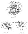
- FIGS 7-10 are drawings of Example 2 of the invention.
- Figure 7 is a diagram showing the internal structure of the connector covered with the upper cap.
- Figure 8 shows the bottom side of the upper cap.
- Figure 9 describes the top side of the lower cap.
- Figure 10 is a cross-sectional view along cut line X-X of Figure 7.
- Figure 11 is a schematic diagram of the cable of Example 3.
- C1 and C1′ are bus cables;
- C2 is a branching cable;
- D1a , D1b , D1a′ , D1b′ , D2a and D2b are insulated wires;
- S1 , S1′ and S2 are treated portions or ends of the shield material;
- 1 and 31 are casing;
- 1A , 31A and 91 are casing main body;
- 2 , 3 , 4 , 32 , 33 and 34 are female portions (positioning portions);
- 91a , 91b and 91c are openings in a positioning portion;
- 12 , 13 , 14 , 42 , 43 , and 44 are binding terminal portions (binding portions);
- 21a , 21b , 22a , 22b , 93a , 93b , 94a and 94b are serrated blades for cutting through the coating of the insulated wire (IDC terminal);
- 55 to 60 are IDC terminals;
- Figure 1 shows that the branching connector M of Example 1 contains casing 1 which is made from a resin or polymer, for example, and the casing consists of the casing main body 1A , upper cap 1B and lower cap 1C .
- Figure 2 shows the connecting configuration of the cables inside casing 1 .
- C1 represents the bus cable that runs continuously from left to right and C2 represents the branching cable.
- the cables of C1 and C2 are shielded cables of the same type.
- the shielded cable consists of a pair of insulated wires D1a and D1b or D2a and D2b .
- the outside of the pair of insulated wires is surrounded with a shield material, and the outside of the shield material is wrapped with a resin or polymer shell.
- the outer shells of the branching portion of bus cable C1 and the end of branching cable C2 are removed and the shield materials are peeled away. Afterward, the insulated wires D1a , D1b , D2a and D2b are exposed. Next, the branching portion of bus cable C1 and the end of branching cable C2 are inserted into predetermined positions in casing 1 . The end portions of peeled shield materials S1 and S2 are wrapped onto the outer shell and a commonly-known end-portion treatment is then performed. In Figure 2, the treated end portions of the shield materials are indicated by the notations S1 , S1′ and S2 (i .e. the portions are indicated with "x").
- Casing main body 1A is a rectangular plate-like body with a thickness greater than the diameter of cable C1 or C2 .
- the upper part of said casing main body consists of half-circle female parts 2 , 3 and 4 (positioning portions) and connected guiding grooves, 5 , 6 , 7 , and 8 .
- the female portions 2 and 3 are formed along the same straight line.
- the two ends of the branching portion of the bus cable C1 are positioned in said female portions 2 and 3 . Accordingly, the two treated end portions S1 and S1′ of the shield material of the branching portion of bus cable C1 are placed in female portions 2 and 3 as shown in Figure 2.
- the female portions 4 and 3 are formed in a parallel manner.
- the end of branching cable C2 is positioned in female portion 4 . Accordingly, treated end portion S2 of the shield material of the end of branching cable C2 is placed in female portion 4 .
- insulated wires to be interconnected are placed in guiding grooves 5 and 6 . Accordingly, guiding grooves 5 and 6 are placed next to each other. Next, insulated wire D1a of bus cable C1 is inserted into guiding groove 5 , which is connected to female portions 2 and 3 as shown in Figure 2 and insulated wire D2a of branching cable 2 is inserted into guiding groove 6 , which is connected to female portion 4 as shown in Figure 2.
- insulated wires to be interconnected are placed in guiding grooves 7 and 8 . Accordingly, guiding grooves 7 and 8 are placed next to each other. Next, insulated wires D1b of bus cable C1 is inserted into guiding groove 7 , which is connected to female portions 3 and 4 as shown in Figure 2, and insulated wire D2b of branching cable 2 is inserted into guiding groove 8 , which is connected to female portion 4 as shown in Figure 2.
- Grooves 2a , 3a and 4a are formed around the female portions 2 , 3 and 4 in such a manner that binding terminal portions (binding portions) 12 , 13 an 14 can be inserted into grooves 2a , 3a and 4a , as shown in Figure 4.
- the binding terminal portions (binding portions) will be described below.
- Grooves 2a , 3a and 4a are respectively formed in a direction which is orthogonal to the axial lines of female portions 2 , 3 and 4 . Accordingly, cables C1 and C2 and binding terminal portions 12 , 13 and 14 can be guided and positioned in an orthogonal manner.
- a pair of parallel portions are formed in guiding grooves 5 and 6 , and rectangular openings 15 are formed along the pair of parallel portions.
- Rectangular openings 15 which pass through the casing main body 1A in an up-down direction, are designed to accept the insertion of IDC terminal plate 21 (see Figure 5).
- Rectangular openings 15 which have the shape of a slot are formed in such a manner that the length thereof is orthogonal with guiding grooves 5 and 6 and are cut in such a manner that the cutting traverses across grooves 5 and 6 , cutting away the side walls of grooves 5 and 6 as shown in Figure 3.
- terminal plate 21 is guided and positioned orthogonally into guiding grooves 5 and 6 .
- Rectangular openings 16 for accepting the insertion of IDC terminal plate 22 are formed next to guiding grooves 7 and 8 in the same manner.
- IDC terminal plate 21 is inserted into rectangular openings 16
- IDC terminal plate 22 is guided and positioned orthogonally into guiding grooves 7 and 8 .
- FIG. 4 shows binding terminal portions 12 , 13 and 14 used respectively to bind treated end portions S1 and S1′ of the shield material of the branching portion of bus cable C1 and treated end portion S2 of the shield material of branching cable C2 .
- Binding terminal portions 12 , 13 and 14 are constructed in the form of a single integrated body on single metal plate 11 . Accordingly, these binding terminal portions are interconnected.
- Single metal plate 11 containing binding terminal portions 12 , 13 and 14 is fixed on the lower side of upper cap 1B .
- Pressure-bonding terminal plate 21 shown in Figure 5 is used to interconnect insulated wires D1a and D2a which are inserted respectively into guiding grooves 5 and 6 (the insulated wires D1a and D2a are wires to be interconnected).
- IDC terminal plate 21 contains two serrated blades 21a and 21b for connecting wires D1a and D2a .
- Serrated blade 21a is allowed to cut into insulated wire D1a in a manner shown in Figure 6. As a result of said action, the resin coating of wire D1a is severed and the interior conductive wire and serrated blade 21a become interconnected.
- two pressing parts 18 are formed on upper cap 1B in a manner shown in Figure 4 wherein pressing parts 18 can press against insulated wire D1a at each side of serrated blade 21a .
- IDC terminal plate 22 is used to interconnect insulated wires D2a and D2b , which are inserted respectively into guiding grooves 7 and 8 (insulated wires D2a and D2b are wires to be interconnected).
- IDC terminal plate 22 contains two serrated blades 22a and 22b for connecting wires D2a and D2b .
- IDC terminal plates 21 and 22 are fixed onto lower cap 1C .
- upper cap 1B , lower cap 1C , and casing main body 1A prefferably be formed into a single integrated body by means of hinges.
- branching cable C2 is brought out from bus cable C1 using the connector with the above structure, the outer shell of the branching portion of the cable C1 is removed, the shield material is peeled away and an end portion treatment is performed on the shield material of the two ends of the branching portion. Afterward, interior insulated wires D1a and D1b are exposed. The end portion of branching cable C2 is also treated in the same manner. Afterward, insulated wires D2a and D2b are exposed.
- the branching portion of bus cable C1 and the end of branching cable C2 are now housed and positioned into casing main body 1A .
- the two treated end portions S1 and S1′ of the shield material of the branching portion of bus cable C1 are respectively placed into female portions 2 and 3 , and treated end portion S2 of the shield material of branching cable C2 is placed into female portion S2 .
- Exposed insulated wire D1a of bus cable C1 is inserted into guiding groove 5 and insulated wire D1b is inserted into guiding groove 7 .
- insulated wire D2a of branching cable C2 for connecting with insulated wire D1a is inserted into guiding groove 6
- insulated wire D2b of branching cable C2 for connecting with insulated wire D1b is inserted into guiding groove 8 .
- upper cap 1B is placed on the upper side of casing main body 1A . Accordingly, binding terminal portions 12 , 13 and 14 placed on the lower side of the upper cap are respectively bound to treated end portions S1 , S1′ and S2 of the shield material. As a result, the shield material of bus cable C1 and the shield material of branching cable C2 are entirely interconnected.
- Lower cap 1C is now fixed to the lower side of casing main body 1A . Accordingly, pressure-bonding terminal plates 21 and 22 which have been integrated onto lower cap 1C are respectively inserted into rectangular openings 15 and 16 of casing main body 1A , and serrated blades 21a , 21b , 22a and 22b are respectively pressed onto insulating wires D1a , D2a , D1b and D2b . Insulated wires D1a and D2a are now conductively interconnected and insulated wires D1b and D2b are conductively interconnected. As lower cap 1C is fixed to the lower side of casing main body 1A , pressing parts 18 formed on upper cap 1B are fitted into guiding grooves 5 , 6 , 7 and 8 . As a result, the insulated wires are pressed into place.
- the branching operation using the connector of the present example only involves positioning each cable into casing main body 1A and sequentially covering the casing main body with upper cap 1B and lower cap 1C as described above.
- Example 2 is described in Figures 7-10.
- This example shows a connector with which the members of the bus cable can be connected and branched.
- C1 and C1′ are the bus cable and C2 is the branching cable.
- This example can also be conceived as an example wherein one cable is branched into two branched cables.
- the connector of this practical example is defined as a connector with which the members of the bus cable can be connected and branched ( C1 and C1′ are the bus cable and C2 is the branching cable).
- the connecting portions of bus cable C1 and C1′ correspond to the branching portion of bus cable C1 of Example 1.
- the respective insulated wires D1a , D1b , D1a′ , D1b′ , D2a and D2b of the ends of cables C1 , C1′ and C2 are exposed and an end treatment is performed on the end portion of the shield material.
- the treated end portions of the shield material are shown by S1 , S1′ and S2 .
- Connector casing 31 consists of casing main body 31A shown in Figure 7, upper cap 31B shown in Figure 8, and lower cap 31C shown in Figure 9.
- the female portions (positioning portions) 32 , 33 , 34 which correspond to female portions 2 , 3 and 4 of Example 1, are formed on the upper side of casing main body 31A , as shown in Figure 8.
- Female portion 32 is formed in the middle of the left end of casing main body 31A along the width direction, and female portions 33 and 34 are respectively formed in positions which are away from the middle of the right end of casing main body 31A along the width direction.
- Grooves 32a , 33a and 34a are formed around the female portions 32 , 33 and 34 , respectively for guiding and positioning respective binding terminal portions (binding portions) 42 , 43 , and 44 placed on the lower side of upper cap 31B .
- Binding terminal portions 42 , 43 , and 44 are for interconnecting treated end portions S1 , S1′ and S2 of the shield material of cables C1 , C1′ and C2 , and are formed on a single piece of metal plate 45 in an interconnected manner, as shown in Figure 8.
- This single piece of metal plate 45 containing binding terminal portions 42 , 43 and 44 , is fixed on the lower side of upper cap 31B .
- the same pressing portions 18 used in Example 1, which are made of a resin or plastic, are placed on the lower side of upper cap 31B .
- Guiding grooves 35 , 36 , 37 , 38 , 39 and 40 for guiding insulated wires D1a′ , D1b′ , D1a , D1b , D2a and D2b are formed in such a manner that the guiding grooves and female portions 32 , 33 and 34 are connected, as shown in Figure 7. All of these guiding grooves 35 to 40 run in a parallel manner.
- Respective rectangular openings 65 , 66 , 67 , 68 , 69 and 70 which are designed to accept the insertion of IDC terminals 55 , 56 , 57 , 58 , 59 and 60 , shown in Figure 9, are made along guiding grooves 35 , 36 , 37 , 38 , 39 and 40 .
- Rectangular openings 65 , 67 and 69 which pass through guiding grooves 35 , 37 and 39 used to interconnect the first group of insulated wires D1a′ , D1a and D2a , are aligned in one row, which is orthogonal to guiding grooves 35 to 40 .
- These rectangular openings are tied together by means of groove 80 formed in the lower side of casing main body 31A in a manner shown in Figure 10 .
- Pressure-bonding terminals 55 , 57 and 59 are interconnected.
- the base portion of terminal plate 81 is then inserted into groove 80 in a manner that allows the insertion of each of IDC terminals 55 , 57 and 59 into each of rectangular openings 65 , 67 and 69 .
- Remaining rectangular openings 66 , 68 and 70 are aligned in one row, which is orthogonal to guiding grooves 35 to 40 at a location away from the row of rectangular openings, as shown in Figure 7.
- IDC terminals 56 , 58 and 60 for inserting into rectangular openings 66 , 68 and 70 are formed on a single piece of terminal plate 82 in such a manner that IDC terminals 56 , 58 and 60 are interconnected. Terminal plate 82 is then inserted into a groove that ties together rectangular openings 66 , 68 and 70 (diagram omitted) in a manner that allows the insertion of each of the IDC terminals 56 , 58 and 60 into each of the rectangular openings 66 , 68 and 70 .
- IDC terminals 55 to 60 are respectively connected to insulated wires D1a′ , D1b′ , D1a , D1b , D2a and D2b in a (conductive) interconnecting manner shown in Figure 7. These IDC terminals are fixed onto the upper side of lower cap 31C in the form of terminal plates 81 and 82 .
- the outer shells of the ends of cable C1 , C1′ and C2 are removed, the shield materials are peeled away, an end portion treatment is performed on the shield materials, and interior insulated wires D1a , D1b , D1a′ , D1b′ , D2a and D2b are exposed.
- treated end portions S1 and S1′ of the shield material of bus cables C1 and C1′ are respectively placed into female portions 32 and 33
- treated end portion S2 of the shield material of branching cable C2 is placed into female portion 34 .
- exposed insulated wire D1a of bus cable C1 is inserted into guiding groove 37
- exposed insulated wire D1b is inserted into guiding groove 38 .
- Insulated wire D1b of the cable C1′ (connected to the insulated wire D1a) is inserted into guiding groove 34 and insulated wire D1b′ of the cable C1′ (connected to insulated wire D1b ) is inserted into guiding groove 36 .
- Insulated wire D2a of cable C2 (connected to insulated wire D1a ) is inserted into guiding groove 39 and insulated wire D2b of cable C2 (connected to insulated wire D1b ) is inserted into guiding groove 40 .
- Upper cap 31B is placed on the upper side of casing main body 31A .
- binding terminal portions 32 , 33 and 34 are respectively bound to treated end portions S1 , S1′ and S2 of the shield materials, and all of the shield materials of cables C1 and C1′ and branching cable C2 are interconnected thereupon.
- Lower cap 31C is fixed to the lower side of the casing main body 31A . This action leads to the respective insertion of IDC terminals 55 to 60 into rectangular openings 65 to 70 in casing main body 31A .
- the IDC terminals are formed on lower cap 31 as a single integrated body.
- pressure-bonding terminals 55 to 60 cut into insulated wires D1a′ , D1b′ , D1a , D1b , D2a and D2b situated in guiding grooves 35 to 40 and become connected to the insulated wires in such a manner that insulated wires D1a′ , D1a and D2a and insulated wires D1b ′ , D1b and D2b are conductively interconnected.
- pressing parts 18 formed on upper cap 31B are fitted into guiding grooves 35 to 40 to press the insulated wires into place.
- the branching operation using the connector of Example 2 only involves positioning each cable into casing main body 31A and sequentially covering the casing main body with upper cap 31B and lower cap 31C .
- metal plates 11 and 45 are placed on the inner surface of upper caps 1A and 31A in the form of a single integrated body and are configured in such a way that metal plates 11 and 45 act as a shield.
- a better interconnection with metal plate 11 or 45 can be obtained by placing or applying a metal plating onto the sides of casing main body 1A or 31A and/or lower cap 1C or 31C in a manner that the entire surface of the branching connector is covered with a shield material.
- binding terminal portions (binding portions) 12 , 13 , 14 , 42 , 43 and 44 are formed on upper cap 1B and 31B . It is also acceptable that metal plates be mounted onto positioning female portions 2, 3 , 4 , 32 , 33 and 34 and that serrated materials, such as for binding the shield material (binding portions), are formed on the metal plates mounted on the female portions. When this configuration is used, all of the metal plates are connected.
- casings 1 and 31 consist of main bodies 1A and 31A , upper caps 1B and 31B , and lower caps 1C and 31C .
- Example 3 is also described in Figure 11.
- casing main body 91 is made of a metal and the sides of the casing main body contain openings 91a and 91b (positioning portions) for bus cable C1 to pass through and opening 91c (positioning portion) for the insertion of branching cable C2 .
- Serrated binders are formed around openings 91a , 91b and 91c . All of the shield materials can be interconnected by binding these serrated binders to treated end portions S1 , S1′ and S2 of the shield materials.
- Terminal plate 93 which contains serrated blades 93a and 93b (the cutting action of the serrated blades is equivalent to that of an IDC terminal) for cutting through the coating material of the insulated wires
- terminal plate 94 which contains serated blades 94a and 94b , is formed onto cap body 92 .
- bus cable C1 is then inserted through openings 91a and 91b of casing main body 91 and the end of branching cable C2 is inserted into opening 91c .
- the serrated material around the openings is then used to bind treated end portions S1 , S1′ and S2 of the shield materials.
- the casing main body is covered with cap body 92 .
- insulated wires D1a and D2a to be connected are conductively interconnected by terminal plate 93 and insulated wires D1b and D2b are conductively interconnected by terminal plate 94 . Afterward, the branching operation is completed.
Landscapes
- Connections By Means Of Piercing Elements, Nuts, Or Screws (AREA)
- Multi-Conductor Connections (AREA)
Description
- The present invention relates to a branching connector according to the pre-characterizing part of claim 1.
- In the past, connector systems for coaxial cables have been used as branching connectors for shielded cables. However, in the case of shielded paired wire cables, the branching operation cannot be performed in a simple manner and suitable connectors have not been available for banching shielded cables which contain a multiplicity of insulates wires.
- DE-A-34 18 582 discloses a branching connector according to the pre-characterizing part of claim 1. In this prior art connector, the bus cable and the branching cable are positioned at an angle of 90° within the main party of the casing. The exposed insulated wires of each cable are introduced into slits of terminal plates, the slits piercing the insulation of the wires. The insulated exposed wires must be fed from the entry of the casing to the respective slits of the terminal plates.
- The object of the present invention is to provide for a branching connector which allows the branching operation be performed in a simple manner.
- This object is achieved by a connector in accordance with claim 1.
- The branching connector is a branching connector for a shielded cable wherein the cable is formed by enclosing a multiplicity of insulated wires within a shield material. The branching connector has a casing that accomodates the branching portions of the bus cable and the terminal portions of the branching cable wherein the outer shell and shield material of each cable have been peeled away and the insulated wires are exposed. The casing contains positioning means for positioning the two ends of the branching portions of the bus cable and other positioning means for positioning the terminals of the branch cable. Conductive binders surround the shield material of the bus cable and the shield material of each branch cable. Insulation displacement contact (IDC) terminals connect the conductive wires of each exposed insulated wire of the bus cables and the branching cables by severing the insulation coating thereof. The same members of the binders are interconnected and the same members of the terminals for connecting the insulated wires to be connected are interconnected.
- IDC terminals that have interconnecting relationships may be formed as a single integrated body.
- In cases where the connector is used to connect the branching cable to the bus cable, the outer shell of the branching portion of the bus cable is first removed, the shield material is peeled away, and an end-portion treatment is performed on the two ends of the branching portions of the shield material. Afterward, the inner insulated wires are exposed. The same treatment is also performed on the end of the branching cable.
- The ends of the branching portions of the bus cable and branching cable are then inserted into the casing of the connector and positioned therein.
- At the same time, the exposed insulated wires to be interconnected are grouped together and positioned in the casing.
- The binders in the casing are then connected with the treated end portions of the shield material of the bus cable and the interconnected members of the binders and the same member of the IDC terminals for connecting the insulated wires are interconnected.
- With this procedure, the shield material of the bus cable and the shield material of the branching cable are connected electrically, the insulated wires are connected, and the branching of the bus cable can then be completed.
-
- Figures 1-6 are drawings of Example 1 of the invention.
- Figure 1 shows a side view of the outer configuration of the connector of Example 1.
- Figure 2 is a cross-sectional view of the connector of Figure 1 along cut line II-II.
- Figure 3 describes the top of the casing main body.
- Figure 4 shows a view of the bottom side of the upper cap.
- Figure 5 shows a view of the top side of the lower cap.
- Figure 6 describes the binding configuration between the IDC terminals and the insulated wires.
- Figures 7-10 are drawings of Example 2 of the invention.
- Figure 7 is a diagram showing the internal structure of the connector covered with the upper cap.
- Figure 8 shows the bottom side of the upper cap.
- Figure 9 describes the top side of the lower cap.
- Figure 10 is a cross-sectional view along cut line X-X of Figure 7.
- Figure 11 is a schematic diagram of the cable of Example 3.
- The invention is now described with reference to the examples and the figures to more clearly delineate the boundaries of the invention.
- In the Examples, C1 and C1′ are bus cables; C2 is a branching cable; D1a, D1b, D1a′, D1b′, D2a and D2b are insulated wires; S1, S1′ and S2 are treated portions or ends of the shield material; 1 and 31 are casing; 1A, 31A and 91 are casing main body; 2, 3, 4, 32, 33 and 34 are female portions (positioning portions); 91a, 91b and 91c are openings in a positioning portion; 12, 13, 14, 42, 43, and 44 are binding terminal portions (binding portions); 21a, 21b, 22a, 22b, 93a, 93b, 94a and 94b are serrated blades for cutting through the coating of the insulated wire (IDC terminal); 55 to 60 are IDC terminals; 21, 22, 93 and 94 are IDC terminal plate; 81 and 82 are terminal plates.
- Figures 1-6 apply to Example 1.
- Figure 1 shows that the branching connector M of Example 1 contains casing 1 which is made from a resin or polymer, for example, and the casing consists of the casing
main body 1A,upper cap 1B andlower cap 1C. Figure 2 shows the connecting configuration of the cables inside casing 1. In Figure 2, C1 represents the bus cable that runs continuously from left to right and C2 represents the branching cable. The cables of C1 and C2 are shielded cables of the same type. The shielded cable consists of a pair of insulated wires D1a and D1b or D2a and D2b. The outside of the pair of insulated wires is surrounded with a shield material, and the outside of the shield material is wrapped with a resin or polymer shell. - The outer shells of the branching portion of bus cable C1 and the end of branching cable C2 are removed and the shield materials are peeled away. Afterward, the insulated wires D1a, D1b, D2a and D2b are exposed. Next, the branching portion of bus cable C1 and the end of branching cable C2 are inserted into predetermined positions in casing 1. The end portions of peeled shield materials S1 and S2 are wrapped onto the outer shell and a commonly-known end-portion treatment is then performed. In Figure 2, the treated end portions of the shield materials are indicated by the notations S1, S1′ and S2 (i .e. the portions are indicated with "x").
- Casing
main body 1A is a rectangular plate-like body with a thickness greater than the diameter of cable C1 or C2. The upper part of said casing main body consists of half-circlefemale parts 2, 3 and 4 (positioning portions) and connected guiding grooves, 5, 6, 7, and 8. - The
female portions 2 and 3 are formed along the same straight line. The two ends of the branching portion of the bus cable C1 are positioned in saidfemale portions 2 and 3. Accordingly, the two treated end portions S1 and S1′ of the shield material of the branching portion of bus cable C1 are placed infemale portions 2 and 3 as shown in Figure 2. The female portions 4 and 3 are formed in a parallel manner. The end of branching cable C2 is positioned in female portion 4. Accordingly, treated end portion S2 of the shield material of the end of branching cable C2 is placed in female portion 4. - The insulated wires to be interconnected are placed in guiding
grooves grooves groove 5, which is connected tofemale portions 2 and 3 as shown in Figure 2 and insulated wire D2a of branchingcable 2 is inserted into guidinggroove 6, which is connected to female portion 4 as shown in Figure 2. - The insulated wires to be interconnected are placed in guiding
grooves grooves groove 7, which is connected to female portions 3 and 4 as shown in Figure 2, and insulated wire D2b of branchingcable 2 is inserted into guidinggroove 8, which is connected to female portion 4 as shown in Figure 2. -
Grooves female portions 2, 3 and 4 in such a manner that binding terminal portions (binding portions) 12, 13 an 14 can be inserted intogrooves Grooves female portions 2, 3 and 4. Accordingly, cables C1 and C2 and bindingterminal portions - A pair of parallel portions are formed in guiding
grooves rectangular openings 15 are formed along the pair of parallel portions.Rectangular openings 15, which pass through the casingmain body 1A in an up-down direction, are designed to accept the insertion of IDC terminal plate 21 (see Figure 5).Rectangular openings 15 which have the shape of a slot are formed in such a manner that the length thereof is orthogonal with guidinggrooves grooves grooves IDC terminal plate 21 are caused to slide into the cut-away portions andIDC terminal plate 21 is inserted intorectangular openings 15,terminal plate 21 is guided and positioned orthogonally into guidinggrooves -
Rectangular openings 16 for accepting the insertion ofIDC terminal plate 22 are formed next to guidinggrooves IDC terminal plate 21 is inserted intorectangular openings 16,IDC terminal plate 22 is guided and positioned orthogonally into guidinggrooves - Figure 4 shows binding
terminal portions terminal portions single metal plate 11. Accordingly, these binding terminal portions are interconnected.Single metal plate 11 containing bindingterminal portions upper cap 1B. - Pressure-
bonding terminal plate 21 shown in Figure 5 is used to interconnect insulated wires D1a and D2a which are inserted respectively into guidinggrooves 5 and 6 (the insulated wires D1a and D2a are wires to be interconnected).IDC terminal plate 21 contains twoserrated blades Serrated blade 21a is allowed to cut into insulated wire D1a in a manner shown in Figure 6. As a result of said action, the resin coating of wire D1a is severed and the interior conductive wire andserrated blade 21a become interconnected. In order to obtain a desirable cutting effect, twopressing parts 18 are formed onupper cap 1B in a manner shown in Figure 4 whereinpressing parts 18 can press against insulated wire D1a at each side ofserrated blade 21a. - Meanwhile,
IDC terminal plate 22 is used to interconnect insulated wires D2a and D2b, which are inserted respectively into guidinggrooves 7 and 8 (insulated wires D2a and D2b are wires to be interconnected).IDC terminal plate 22 contains twoserrated blades IDC terminal plates lower cap 1C. - It is acceptable for
upper cap 1B,lower cap 1C, and casingmain body 1A to be formed into a single integrated body by means of hinges. - The effects of the branching connector with the above structure are now described.
- In cases where branching cable C2 is brought out from bus cable C1 using the connector with the above structure, the outer shell of the branching portion of the cable C1 is removed, the shield material is peeled away and an end portion treatment is performed on the shield material of the two ends of the branching portion. Afterward, interior insulated wires D1a and D1b are exposed. The end portion of branching cable C2 is also treated in the same manner. Afterward, insulated wires D2a and D2b are exposed.
- The branching portion of bus cable C1 and the end of branching cable C2 are now housed and positioned into casing
main body 1A. The two treated end portions S1 and S1′ of the shield material of the branching portion of bus cable C1 are respectively placed intofemale portions 2 and 3, and treated end portion S2 of the shield material of branching cable C2 is placed into female portion S2. Exposed insulated wire D1a of bus cable C1 is inserted into guidinggroove 5 and insulated wire D1b is inserted into guidinggroove 7. Also insulated wire D2a of branching cable C2 for connecting with insulated wire D1a is inserted into guidinggroove 6, and insulated wire D2b of branching cable C2 for connecting with insulated wire D1b is inserted into guidinggroove 8. - Next,
upper cap 1B is placed on the upper side of casingmain body 1A. Accordingly, bindingterminal portions -
Lower cap 1C is now fixed to the lower side of casingmain body 1A. Accordingly, pressure-bonding terminal plates lower cap 1C are respectively inserted intorectangular openings main body 1A, andserrated blades lower cap 1C is fixed to the lower side of casingmain body 1A, pressingparts 18 formed onupper cap 1B are fitted into guidinggrooves - To summarize, the branching operation using the connector of the present example only involves positioning each cable into casing
main body 1A and sequentially covering the casing main body withupper cap 1B andlower cap 1C as described above. - Example 2 is described in Figures 7-10.
- This example shows a connector with which the members of the bus cable can be connected and branched. In Figure 7, C1 and C1′ are the bus cable and C2 is the branching cable. This example can also be conceived as an example wherein one cable is branched into two branched cables. For convenience, the connector of this practical example is defined as a connector with which the members of the bus cable can be connected and branched (C1 and C1′ are the bus cable and C2 is the branching cable).
- The connecting portions of bus cable C1 and C1′ correspond to the branching portion of bus cable C1 of Example 1. The respective insulated wires D1a, D1b, D1a′, D1b′, D2a and D2b of the ends of cables C1, C1′ and C2 are exposed and an end treatment is performed on the end portion of the shield material. The treated end portions of the shield material are shown by S1, S1′ and S2.
- Connector casing 31 consists of casing
main body 31A shown in Figure 7,upper cap 31B shown in Figure 8, andlower cap 31C shown in Figure 9. The female portions (positioning portions) 32, 33, 34, which correspond tofemale portions 2, 3 and 4 of Example 1, are formed on the upper side of casingmain body 31A, as shown in Figure 8.Female portion 32 is formed in the middle of the left end of casingmain body 31A along the width direction, andfemale portions main body 31A along the width direction. -
Grooves 32a, 33a and 34a are formed around thefemale portions upper cap 31B. Bindingterminal portions metal plate 45 in an interconnected manner, as shown in Figure 8. This single piece ofmetal plate 45, containing bindingterminal portions upper cap 31B. The samepressing portions 18 used in Example 1, which are made of a resin or plastic, are placed on the lower side ofupper cap 31B. - Guiding
grooves female portions rectangular openings IDC terminals grooves -
Rectangular openings grooves 35, 37 and 39 used to interconnect the first group of insulated wires D1a′, D1a and D2a, are aligned in one row, which is orthogonal to guiding grooves 35 to 40. These rectangular openings are tied together by means ofgroove 80 formed in the lower side of casingmain body 31A in a manner shown in Figure 10. Pressure-bonding terminals terminal plate 81 is then inserted intogroove 80 in a manner that allows the insertion of each ofIDC terminals rectangular openings - Remaining
rectangular openings 66, 68 and 70 are aligned in one row, which is orthogonal to guiding grooves 35 to 40 at a location away from the row of rectangular openings, as shown in Figure 7.IDC terminals rectangular openings 66, 68 and 70 are formed on a single piece ofterminal plate 82 in such a manner thatIDC terminals Terminal plate 82 is then inserted into a groove that ties togetherrectangular openings 66, 68 and 70 (diagram omitted) in a manner that allows the insertion of each of theIDC terminals rectangular openings 66, 68 and 70. -
IDC terminals 55 to 60 are respectively connected to insulated wires D1a′, D1b′, D1a, D1b, D2a and D2b in a (conductive) interconnecting manner shown in Figure 7. These IDC terminals are fixed onto the upper side oflower cap 31C in the form ofterminal plates - The effects of the branching connector with the above structure for connecting each cable are now described.
- First, the outer shells of the ends of cable C1, C1′ and C2 are removed, the shield materials are peeled away, an end portion treatment is performed on the shield materials, and interior insulated wires D1a, D1b, D1a′, D1b′, D2a and D2b are exposed.
- Next, the ends are housed into casing
main body 31A and positioned respectively in designated locations. Namely, treated end portions S1 and S1′ of the shield material of bus cables C1 and C1′ are respectively placed intofemale portions female portion 34. In addition, exposed insulated wire D1a of bus cable C1 is inserted into guidinggroove 37 and exposed insulated wire D1b is inserted into guidinggroove 38. Insulated wire D1b of the cable C1′ (connected to the insulated wire D1a) is inserted into guidinggroove 34 and insulated wire D1b′ of the cable C1′ (connected to insulated wire D1b) is inserted into guiding groove 36. Insulated wire D2a of cable C2 (connected to insulated wire D1a) is inserted into guiding groove 39 and insulated wire D2b of cable C2 (connected to insulated wire D1b) is inserted into guiding groove 40. -
Upper cap 31B is placed on the upper side of casingmain body 31A. As a result, bindingterminal portions upper cap 31B) are respectively bound to treated end portions S1, S1′ and S2 of the shield materials, and all of the shield materials of cables C1 and C1′ and branching cable C2 are interconnected thereupon. -
Lower cap 31C is fixed to the lower side of the casingmain body 31A. This action leads to the respective insertion ofIDC terminals 55 to 60 intorectangular openings 65 to 70 in casingmain body 31A. The IDC terminals are formed on lower cap 31 as a single integrated body. As a result, pressure-bonding terminals 55 to 60 cut into insulated wires D1a′, D1b′, D1a, D1b, D2a and D2b situated in guiding grooves 35 to 40 and become connected to the insulated wires in such a manner that insulated wires D1a′, D1a and D2a and insulated wires D1b′ , D1b and D2b are conductively interconnected. Aslower cap 31C is fixed to the lower side of casingmain body 31A, pressingparts 18 formed onupper cap 31B are fitted into guiding grooves 35 to 40 to press the insulated wires into place. - Summarizing, the branching operation using the connector of Example 2 only involves positioning each cable into casing
main body 31A and sequentially covering the casing main body withupper cap 31B andlower cap 31C. - In Examples 1 and 2,
metal plates upper caps metal plates metal plate main body lower cap - In Examples 1 and 2, binding terminal portions (binding portions) 12, 13, 14, 42, 43 and 44 are formed on
upper cap female portions main bodies upper caps lower caps - Example 3 is also described in Figure 11.
- Next, another example is briefly described which concerns the branching connector shown in Figure 11.
- In this branching connector, casing
main body 91 is made of a metal and the sides of the casing main body containopenings 91a and 91b (positioning portions) for bus cable C1 to pass through and opening 91c (positioning portion) for the insertion of branching cable C2. Serrated binders (binding portions) are formed aroundopenings 91a, 91b and 91c. All of the shield materials can be interconnected by binding these serrated binders to treated end portions S1, S1′ and S2 of the shield materials. -
Terminal plate 93 which containsserrated blades terminal plate 94, which containsserated blades 94a and 94b, is formed ontocap body 92. - In a procedure to connect branching
cable 2 to bus cable C1, the branching portion of bus cable C1 and the end of branching cable C2 are treated in the same manner described in Examples 1 and 2. Bus cable C1 is then inserted throughopenings 91a and 91b of casingmain body 91 and the end of branching cable C2 is inserted into opening 91c. Next, the serrated material around the openings is then used to bind treated end portions S1, S1′ and S2 of the shield materials. Afterward, the casing main body is covered withcap body 92. As a result, insulated wires D1a and D2a to be connected are conductively interconnected byterminal plate 93 and insulated wires D1b and D2b are conductively interconnected byterminal plate 94. Afterward, the branching operation is completed. - It is thus illustrated by Examples 1, 2 and 3 that shielded cables containing a multiplicity of insulated wires can be simply branched using the branching connector of the present invention.
Claims (2)
- A branching connector for shielded cables comprising(a) a shielded bus cable (C1) consisting of a multiplicity of insulated wires (D1a, D1b, D1a′, D1b′) enclosed within a shield material which is wrapped with an outer shell, wherein said cable has a portion of said outer shell and shield material removed to expose said insulated wires (D1a, D1b, D1a′, D1b′);(b) one or more shielded branching cables (C2) consisting of a multiplicity of insulated wires (D2a, D2b, D2a′, D2b′) enclosed within a shield material which is wrapped with an outer shell, wherein said cable or cables have a portion of said outer shell and shield material removed to expose said insulated wires (D2a, D2b, D2a′, D2b′);the branching connector comprising:
a casing (1; 31) having a main body (1A; 31A) and a top cap (1B, 31B) to accomodate said bus cable and said branching cables (C1, C2), the casing containing positioning means (2-4); 32-34) for positioning said bus and branching cables on said casing;
characterized in that
said positioning means (2-4; 32-34) are adapted to position said cables in parallel axial alignment;
that guide prooves (5-8; 35-40) are provided in said main body (1A; 31A) for positioning said exposed insulated wires (D1a, D1a′, D1b, D1b′, D2a, D2b);
that rectangular openings (15; 65-70) are formed in said main body (1A; 31A) for insulation displacement contact terminal plates (21, 22; 81, 82; 93, 94) and pressing parts (18) are mounted on said top cap (1B, 31B) of the casing, said insulation displacement contact terminal plates and pressing parts being orthogonally inserted from opposite sides of the main body (1A; 31A) for engagement with said exposed insulated wires for severing the insulation of the exposed insulated wires and making electrical contact therewith;
that said casing (1; 31) also includes a bottom cap (1C; 31C) onto which said insulation displacement contact terminal plates (21, 22; 81, 82; 93, 94) are fixed; and an electrically conductive binder (12-14; 42-44) for engagement with said shield material of said bus cable and said branching cable;
whereby said making of electrical contact and support of said cable are simultaneously effected by assembly of said top and said bottom cap to said main body (1A; 31A). - A branching connector of claim 1, wherein said casing comprises a resin or polymer.
Applications Claiming Priority (2)
| Application Number | Priority Date | Filing Date | Title |
|---|---|---|---|
| JP25939/90 | 1990-02-07 | ||
| JP2025939A JPH03233875A (en) | 1990-02-07 | 1990-02-07 | Branch connector for shielded cable |
Publications (2)
| Publication Number | Publication Date |
|---|---|
| EP0443331A1 EP0443331A1 (en) | 1991-08-28 |
| EP0443331B1 true EP0443331B1 (en) | 1995-08-09 |
Family
ID=12179729
Family Applications (1)
| Application Number | Title | Priority Date | Filing Date |
|---|---|---|---|
| EP91100706A Expired - Lifetime EP0443331B1 (en) | 1990-02-07 | 1991-01-21 | A branch connector for shield cable |
Country Status (3)
| Country | Link |
|---|---|
| EP (1) | EP0443331B1 (en) |
| JP (1) | JPH03233875A (en) |
| DE (1) | DE69111846T2 (en) |
Families Citing this family (4)
| Publication number | Priority date | Publication date | Assignee | Title |
|---|---|---|---|---|
| DE4324841A1 (en) * | 1993-07-23 | 1995-01-26 | Grote & Hartmann | Method and device for supplying electricity to optional, electrically driven special equipment devices, for example in a motor vehicle, an electrically operated domestic appliance or the like |
| FR2797353B1 (en) | 1999-08-04 | 2001-12-14 | Conception & Dev Michelin Sa | ELECTRICAL CONNECTOR USING BODIES PENETRATING IN INSULATION |
| KR20030069258A (en) * | 2002-02-19 | 2003-08-27 | 주식회사 휘라 포토닉스 | Digital signal cross-connection module |
| DE102004001186B4 (en) * | 2004-01-05 | 2005-12-22 | Johnson Controls Interiors Gmbh & Co. Kg | Device and method for laying at least one cable |
Family Cites Families (4)
| Publication number | Priority date | Publication date | Assignee | Title |
|---|---|---|---|---|
| US4533197A (en) * | 1983-05-18 | 1985-08-06 | Prince Thomas F | Junction block for shielded communications network line |
| CA1244900A (en) * | 1983-09-20 | 1988-11-15 | Raychem Corporation | Cable joints and terminations |
| ZA861765B (en) * | 1985-03-14 | 1986-10-29 | Trygve Eric Hvidsten | Cable splice closure |
| US4820190A (en) * | 1987-09-18 | 1989-04-11 | E. I. Du Pont De Nemours And Company | Electrical component mounting and connection assembly |
-
1990
- 1990-02-07 JP JP2025939A patent/JPH03233875A/en active Pending
-
1991
- 1991-01-21 EP EP91100706A patent/EP0443331B1/en not_active Expired - Lifetime
- 1991-01-21 DE DE69111846T patent/DE69111846T2/en not_active Expired - Fee Related
Also Published As
| Publication number | Publication date |
|---|---|
| DE69111846T2 (en) | 1995-12-07 |
| DE69111846D1 (en) | 1995-09-14 |
| EP0443331A1 (en) | 1991-08-28 |
| JPH03233875A (en) | 1991-10-17 |
Similar Documents
| Publication | Publication Date | Title |
|---|---|---|
| US5055064A (en) | Branching connector for a shielded cable | |
| US3708779A (en) | Wire-splicing apparatus and method | |
| US5425657A (en) | Electrical connector assembly and method for terminating a multi-conductor cable | |
| US4065199A (en) | Flat cable wiring harness and method of producing same | |
| US4310208A (en) | Molded electrical connector | |
| US4596428A (en) | Multi-conductor cable/contact connection assembly and method | |
| US4487992A (en) | Shielded electrical cable | |
| US4094564A (en) | Multiple conductor electrical connector with ground bus | |
| US4171857A (en) | Cleat connector for insulated wires | |
| CA1080314A (en) | Electrical connector for use with multi-conductor cables, and a method of connecting such cables | |
| US4379361A (en) | Method for making molded electrical connector | |
| US4153325A (en) | Method and connector for terminating twisted pair and ribbon cable | |
| JP3260759B2 (en) | Wire management adapter for cable termination connection | |
| EP0251736B1 (en) | Wiring holding device in an electrical connector | |
| CA1140227A (en) | Method of terminating shielded electrical cable and an assembly comprising an electrical connector terminating such cable | |
| EP0429962B1 (en) | Multiconductor cable connector and method of loading same | |
| US5281170A (en) | Round-to-flat shielded connector assembly | |
| EP0443331B1 (en) | A branch connector for shield cable | |
| US5850692A (en) | Process of making cable plug connector | |
| US4342152A (en) | Methods of terminating and connectorizing cables | |
| US6007367A (en) | Apparatus for connecting cable cores | |
| US5520549A (en) | Connector apparatus, housing, and connecting element | |
| JPH07249437A (en) | Light conductor connection device | |
| US5238428A (en) | Round-to-flat shielded connector assembly | |
| US4768287A (en) | Method for joining a plug connector to a flat ribbon cable |
Legal Events
| Date | Code | Title | Description |
|---|---|---|---|
| PUAI | Public reference made under article 153(3) epc to a published international application that has entered the european phase |
Free format text: ORIGINAL CODE: 0009012 |
|
| AK | Designated contracting states |
Kind code of ref document: A1 Designated state(s): DE FR GB IT SE |
|
| 17P | Request for examination filed |
Effective date: 19920212 |
|
| 17Q | First examination report despatched |
Effective date: 19940415 |
|
| GRAA | (expected) grant |
Free format text: ORIGINAL CODE: 0009210 |
|
| AK | Designated contracting states |
Kind code of ref document: B1 Designated state(s): DE FR GB IT SE |
|
| ITF | It: translation for a ep patent filed | ||
| REF | Corresponds to: |
Ref document number: 69111846 Country of ref document: DE Date of ref document: 19950914 |
|
| ET | Fr: translation filed | ||
| PLBE | No opposition filed within time limit |
Free format text: ORIGINAL CODE: 0009261 |
|
| STAA | Information on the status of an ep patent application or granted ep patent |
Free format text: STATUS: NO OPPOSITION FILED WITHIN TIME LIMIT |
|
| 26N | No opposition filed | ||
| PGFP | Annual fee paid to national office [announced via postgrant information from national office to epo] |
Ref country code: FR Payment date: 19971218 Year of fee payment: 8 |
|
| PGFP | Annual fee paid to national office [announced via postgrant information from national office to epo] |
Ref country code: SE Payment date: 19971219 Year of fee payment: 8 |
|
| PGFP | Annual fee paid to national office [announced via postgrant information from national office to epo] |
Ref country code: DE Payment date: 19971222 Year of fee payment: 8 |
|
| PGFP | Annual fee paid to national office [announced via postgrant information from national office to epo] |
Ref country code: GB Payment date: 19971223 Year of fee payment: 8 |
|
| PG25 | Lapsed in a contracting state [announced via postgrant information from national office to epo] |
Ref country code: GB Free format text: LAPSE BECAUSE OF NON-PAYMENT OF DUE FEES Effective date: 19990121 |
|
| PG25 | Lapsed in a contracting state [announced via postgrant information from national office to epo] |
Ref country code: SE Free format text: LAPSE BECAUSE OF NON-PAYMENT OF DUE FEES Effective date: 19990122 |
|
| GBPC | Gb: european patent ceased through non-payment of renewal fee |
Effective date: 19990121 |
|
| PG25 | Lapsed in a contracting state [announced via postgrant information from national office to epo] |
Ref country code: FR Free format text: LAPSE BECAUSE OF NON-PAYMENT OF DUE FEES Effective date: 19990930 |
|
| PG25 | Lapsed in a contracting state [announced via postgrant information from national office to epo] |
Ref country code: DE Free format text: LAPSE BECAUSE OF NON-PAYMENT OF DUE FEES Effective date: 19991103 |
|
| REG | Reference to a national code |
Ref country code: FR Ref legal event code: ST |
|
| PG25 | Lapsed in a contracting state [announced via postgrant information from national office to epo] |
Ref country code: IT Free format text: LAPSE BECAUSE OF NON-PAYMENT OF DUE FEES Effective date: 20050121 |